Embed Size (px)
Citation preview
Gas Well Deliquification Workshop
Sheraton Downtown Denver Hotel
Denver, Colorado
February 20 - 22, 2012
Introduction to Plunger Lift
David Cosby, P.E.
Ferguson Beauregard
2 February 20 – 22, 2012
2012 Gas Well Deliquification Workshop
Denver, Colorado
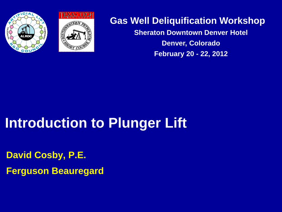
PRIMARY PURPOSE
Remove liquid from a well so that gas can
flow freely to the surface.
How does plunger lift work
Why is artificial lift required
When is plunger lift needed
Benefits, limitations, economics
Key components
Optimizing and Troubleshooting
Safety
Introduction to Plunger Lift
3 February 20 – 22, 2012
2012 Gas Well Deliquification Workshop
Denver, Colorado
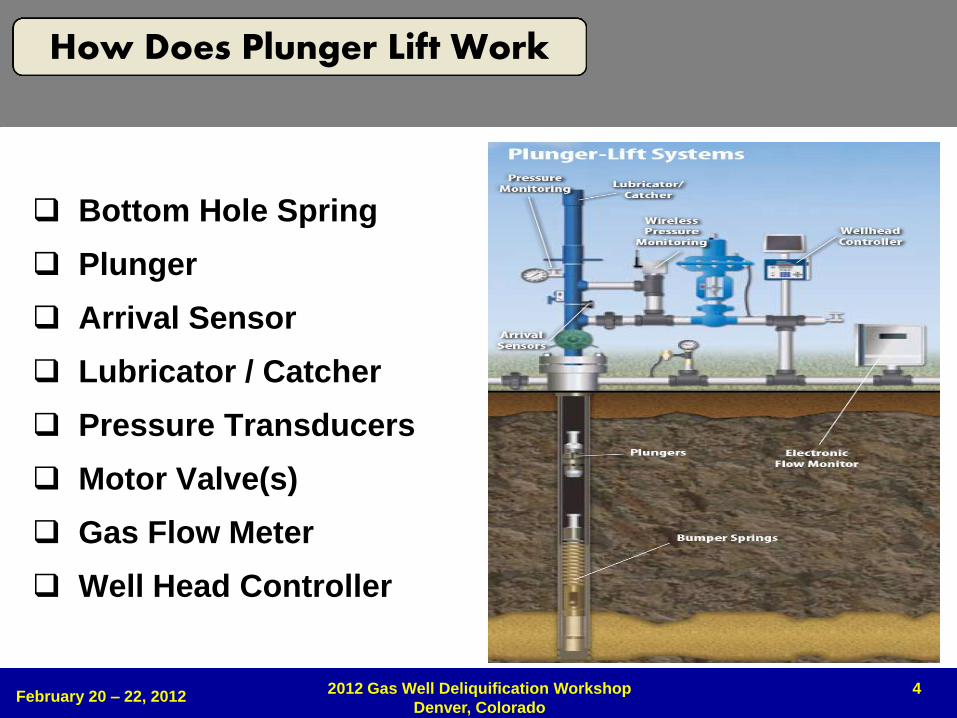
HOW DOES PLUNGER LIFT WORK
4
Bottom Hole Spring
Plunger
Arrival Sensor
Lubricator / Catcher
Pressure Transducers
Motor Valve(s)
Gas Flow Meter
Well Head Controller
February 20 – 22, 2012 2012 Gas Well Deliquification Workshop
Denver, Colorado
How Does Plunger Lift Work
5
CP
TP LP
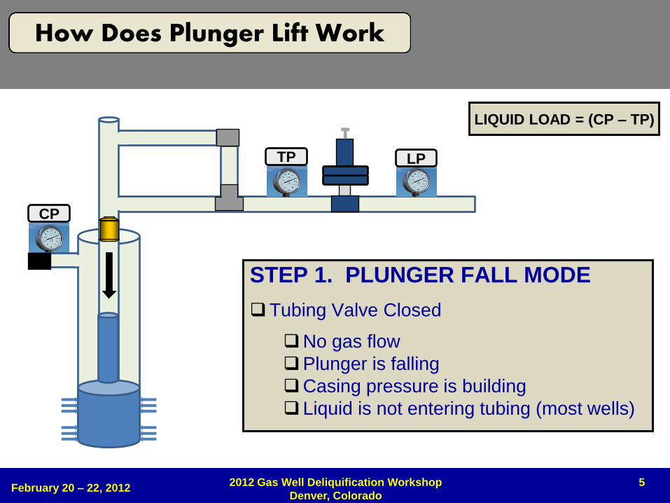
STEP 1. PLUNGER FALL MODE
Tubing Valve Closed
No gas flow
Plunger is falling
Casing pressure is building
Liquid is not entering tubing (most wells)
LIQUID LOAD = (CP – TP)
February 20 – 22, 2012 2012 Gas Well Deliquification Workshop
Denver, Colorado
How Does Plunger Lift Work
6
CP
TP LP
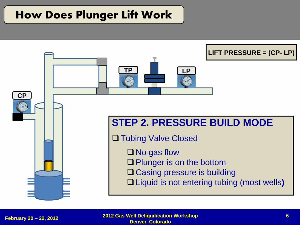
STEP 2. PRESSURE BUILD MODE
Tubing Valve Closed
No gas flow
Plunger is on the bottom
Casing pressure is building
Liquid is not entering tubing (most wells)
LIFT PRESSURE = (CP- LP)
February 20 – 22, 2012 2012 Gas Well Deliquification Workshop
Denver, Colorado
How Does Plunger Lift Work
7
CP
TP LP
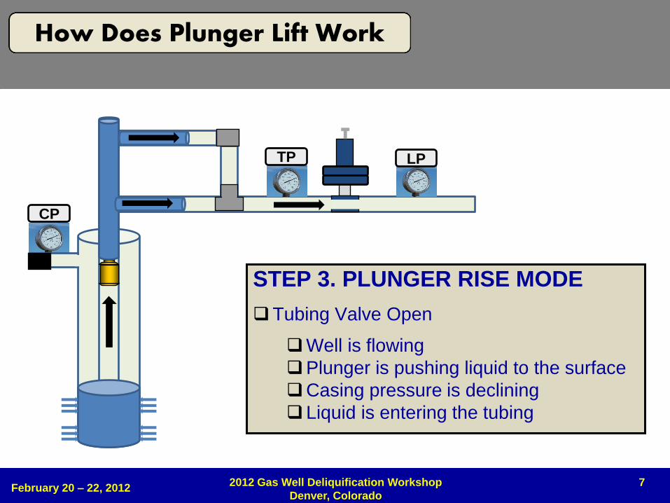
STEP 3. PLUNGER RISE MODE
Tubing Valve Open
Well is flowing
Plunger is pushing liquid to the surface
Casing pressure is declining
Liquid is entering the tubing
February 20 – 22, 2012 2012 Gas Well Deliquification Workshop
Denver, Colorado
How Does Plunger Lift Work
8
CP
TP LP
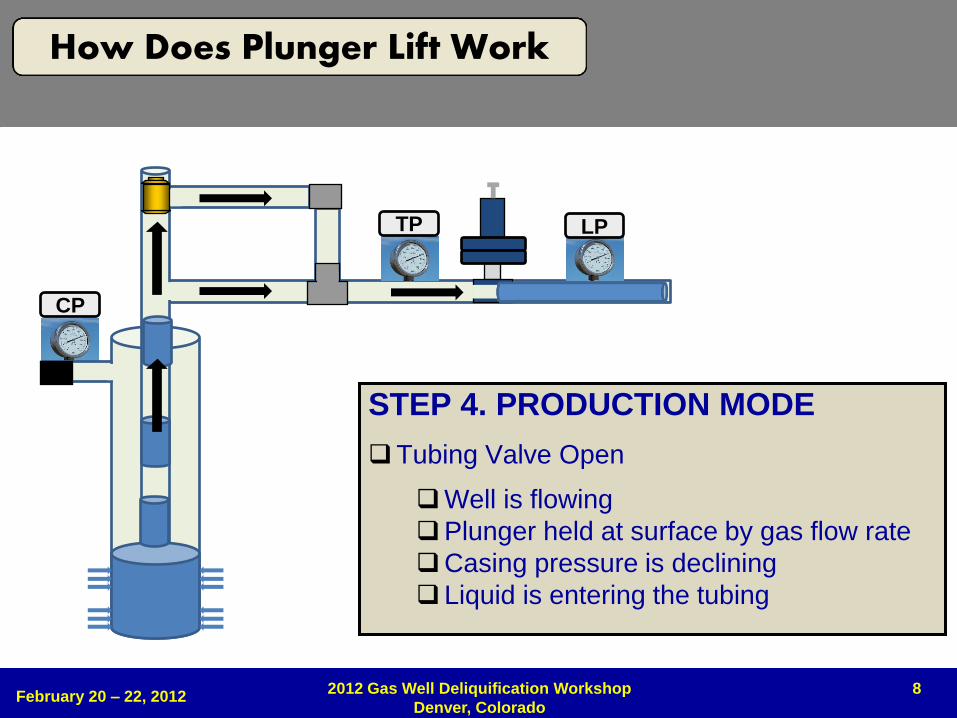
STEP 4. PRODUCTION MODE
Tubing Valve Open
Well is flowing
Plunger held at surface by gas flow rate
Casing pressure is declining
Liquid is entering the tubing
February 20 – 22, 2012 2012 Gas Well Deliquification Workshop
Denver, Colorado
How Does Plunger Lift Work
9 February 20 – 22, 2012
2012 Gas Well Deliquification Workshop
Denver, Colorado
How Does Plunger Lift Work
VIDEO
10
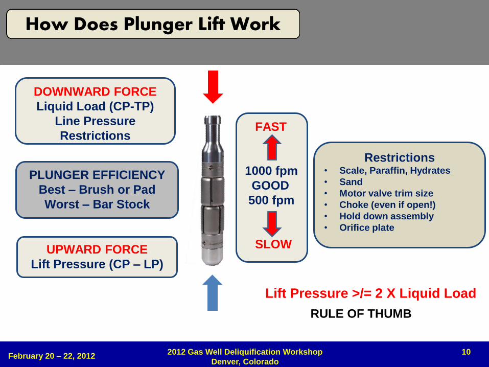
PLUNGER EFFICIENCY
Best – Brush or Pad
Worst – Bar Stock
DOWNWARD FORCE
Liquid Load (CP-TP)
Line Pressure
Restrictions
UPWARD FORCE
Lift Pressure (CP – LP)
FAST
1000 fpm
GOOD
500 fpm
SLOW
Lift Pressure >/= 2 X Liquid Load
RULE OF THUMB
Restrictions • Scale, Paraffin, Hydrates
• Sand
• Motor valve trim size
• Choke (even if open!)
• Hold down assembly
• Orifice plate
February 20 – 22, 2012 2012 Gas Well Deliquification Workshop
Denver, Colorado
How Does Plunger Lift Work
11 February 20 – 22, 2012
2012 Gas Well Deliquification Workshop
Denver, Colorado
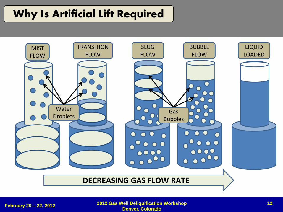
WHY IS ARTIFICIAL LIFT REQUIRED
12
DECREASING GAS FLOW RATE
MIST FLOW
TRANSITION FLOW
SLUG FLOW
BUBBLE FLOW
LIQUID LOADED
Water Droplets
Gas Bubbles
February 20 – 22, 2012 2012 Gas Well Deliquification Workshop
Denver, Colorado
Why Is Artificial Lift Required
13 February 20 – 22, 2012
2012 Gas Well Deliquification Workshop
Denver, Colorado
Why Is Artificial Lift Required
VIDEO
14
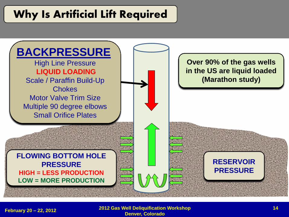
BACKPRESSURE High Line Pressure
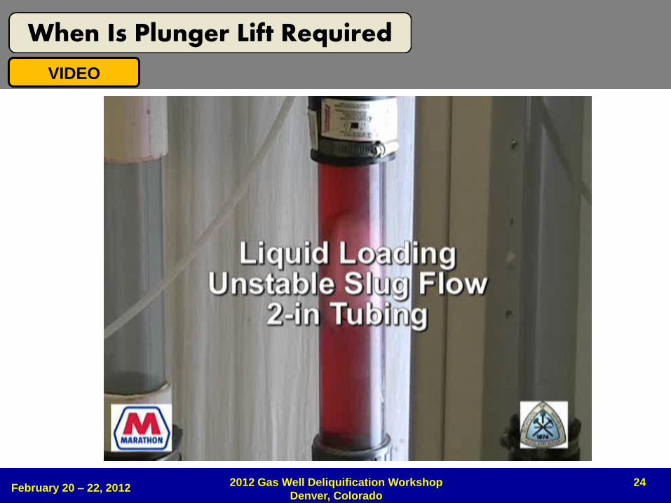
LIQUID LOADING
Scale / Paraffin Build-Up
Chokes
Motor Valve Trim Size
Multiple 90 degree elbows
Small Orifice Plates
RESERVOIR
PRESSURE
Over 90% of the gas wells
in the US are liquid loaded
(Marathon study)
FLOWING BOTTOM HOLE
PRESSURE HIGH = LESS PRODUCTION
LOW = MORE PRODUCTION
February 20 – 22, 2012 2012 Gas Well Deliquification Workshop
Denver, Colorado
Why Is Artificial Lift Required
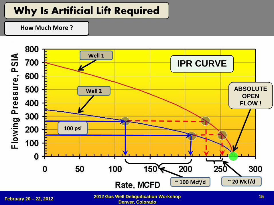
15
IPR CURVE
ABSOLUTE
OPEN
FLOW !
100 psi
~ 100 Mcf/d ~ 20 Mcf/d
Well 1
Well 2
February 20 – 22, 2012 2012 Gas Well Deliquification Workshop
Denver, Colorado
Why Is Artificial Lift Required
How Much More ?
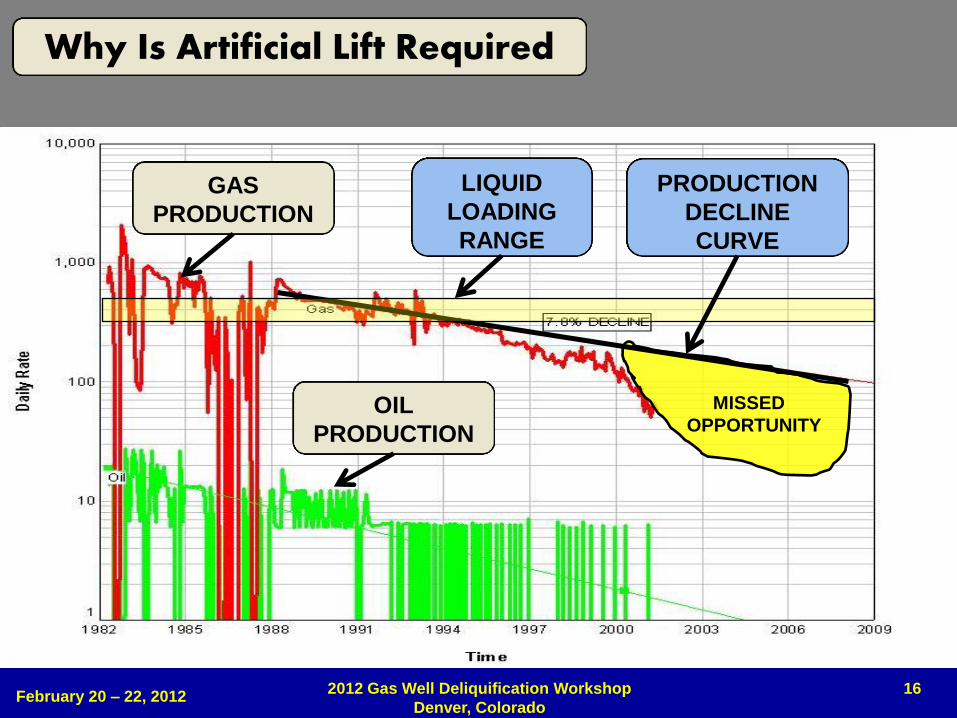
16
GAS
PRODUCTION
OIL
PRODUCTION
MISSED
OPPORTUNITY
PRODUCTION
DECLINE
CURVE
LIQUID
LOADING
RANGE
February 20 – 22, 2012 2012 Gas Well Deliquification Workshop
Denver, Colorado
Why Is Artificial Lift Required
17 February 20 – 22, 2012
2012 Gas Well Deliquification Workshop
Denver, Colorado
WHEN IS PLUNGER LIFT REQUIRED
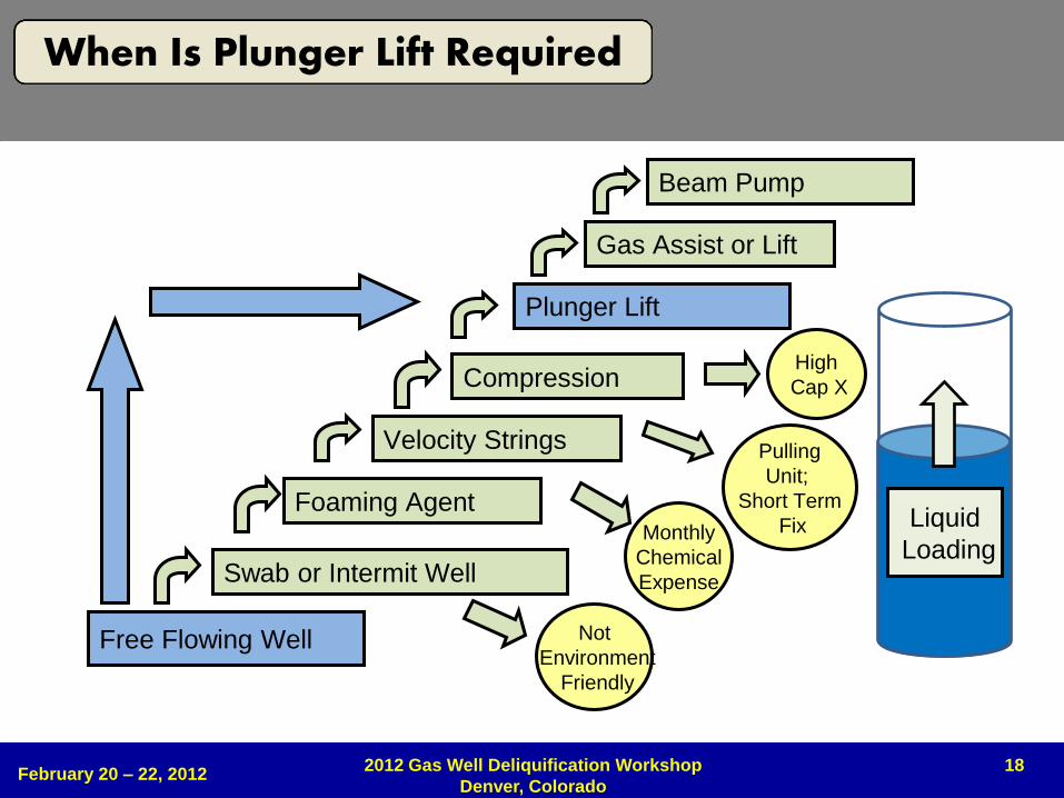
18
Free Flowing Well
Foaming Agent
Velocity Strings
Plunger Lift
Beam Pump
Gas Assist or Lift
Compression
Monthly
Chemical
Expense
Pulling
Unit;
Short Term
Fix
High
Cap X
Swab or Intermit Well
Not
Environment
Friendly
February 20 – 22, 2012 2012 Gas Well Deliquification Workshop
Denver, Colorado
When Is Plunger Lift Required
Liquid
Loading
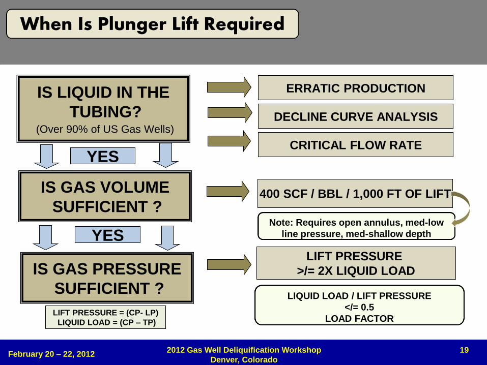
19
IS LIQUID IN THE
TUBING? (Over 90% of US Gas Wells)
ERRATIC PRODUCTION
DECLINE CURVE ANALYSIS
CRITICAL FLOW RATE
IS GAS VOLUME
SUFFICIENT ?
YES
IS GAS PRESSURE
SUFFICIENT ?
YES
400 SCF / BBL / 1,000 FT OF LIFT
LIFT PRESSURE
>/= 2X LIQUID LOAD
LIFT PRESSURE = (CP- LP)
LIQUID LOAD = (CP – TP)
Note: Requires open annulus, med-low
line pressure, med-shallow depth
LIQUID LOAD / LIFT PRESSURE
</= 0.5
LOAD FACTOR
February 20 – 22, 2012 2012 Gas Well Deliquification Workshop
Denver, Colorado
When Is Plunger Lift Required
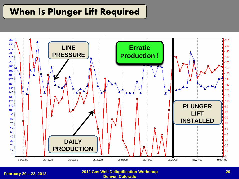
20
LINE
PRESSURE
DAILY
PRODUCTION
PLUNGER
LIFT
INSTALLED
Erratic
Production !
February 20 – 22, 2012 2012 Gas Well Deliquification Workshop
Denver, Colorado
When Is Plunger Lift Required
0
200
400
600
800
1,000
1,200
1,400
1,600
0
200
400
600
800
1,000
1,200
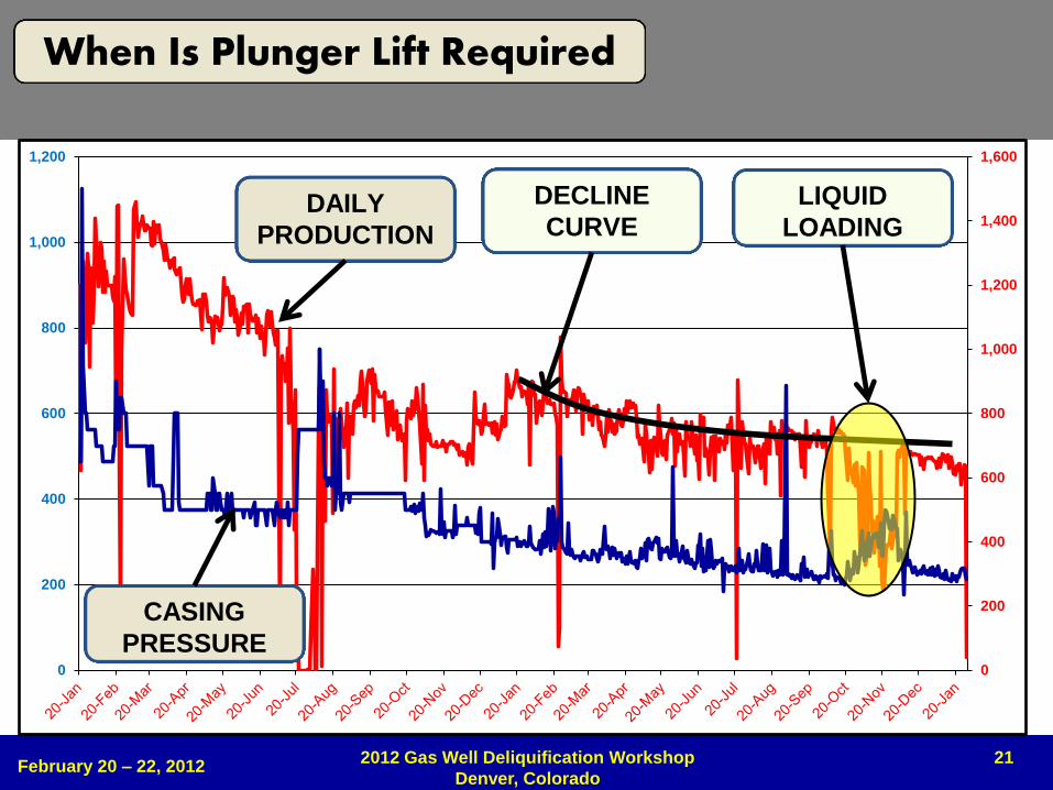
21
DAILY
PRODUCTION
CASING
PRESSURE
DECLINE
CURVE
LIQUID
LOADING
February 20 – 22, 2012 2012 Gas Well Deliquification Workshop
Denver, Colorado
When Is Plunger Lift Required
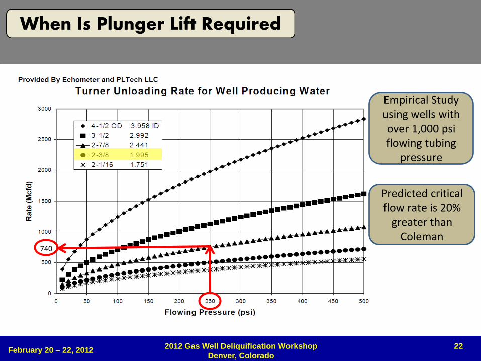
22
Empirical Study using wells with over 1,000 psi flowing tubing
pressure
Predicted critical flow rate is 20%
greater than Coleman
740
February 20 – 22, 2012 2012 Gas Well Deliquification Workshop
Denver, Colorado
When Is Plunger Lift Required
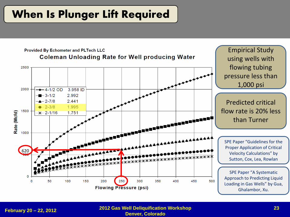
23
Empirical Study using wells with flowing tubing
pressure less than 1,000 psi
Predicted critical flow rate is 20% less
than Turner
620
SPE Paper “Guidelines for the Proper Application of Critical
Velocity Calculations” by Sutton, Cox, Lea, Rowlan
SPE Paper “A Systematic Approach to Predicting Liquid Loading in Gas Wells” by Gua,
Ghalambor, Xu.
February 20 – 22, 2012 2012 Gas Well Deliquification Workshop
Denver, Colorado
When Is Plunger Lift Required
24 February 20 – 22, 2012
2012 Gas Well Deliquification Workshop
Denver, Colorado
When Is Plunger Lift Required
VIDEO
25
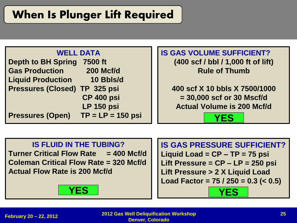
WELL DATA
Depth to BH Spring 7500 ft
Gas Production 200 Mcf/d
Liquid Production 10 Bbls/d
Pressures (Closed) TP 325 psi
CP 400 psi
LP 150 psi
Pressures (Open) TP = LP = 150 psi
IS FLUID IN THE TUBING?
Turner Critical Flow Rate = 400 Mcf/d
Coleman Critical Flow Rate = 320 Mcf/d
Actual Flow Rate is 200 Mcf/d
YES
IS GAS PRESSURE SUFFICIENT? Liquid Load = CP – TP = 75 psi
Lift Pressure = CP – LP = 250 psi
Lift Pressure > 2 X Liquid Load
Load Factor = 75 / 250 = 0.3 (< 0.5)
IS GAS VOLUME SUFFICIENT?
(400 scf / bbl / 1,000 ft of lift)
Rule of Thumb
400 scf X 10 bbls X 7500/1000
= 30,000 scf or 30 Mscf/d
Actual Volume is 200 Mcf/d
YES
YES
February 20 – 22, 2012 2012 Gas Well Deliquification Workshop
Denver, Colorado
When Is Plunger Lift Required

26 February 20 – 22, 2012
2012 Gas Well Deliquification Workshop
Denver, Colorado
BENEFITS
LIMITATIONS
ECONOMICS
27
• Stabilizes and improves production • 10% to 20% production improvement is common
• Keeps tubing clear of debris (Paraffin, scale, hydrates, etc)
• Long term solution – produce well to depletion
• Effective with vertical, directional, s-shaped and horizontal wells
• Produces with a low casing pressure
• Economical • Low capital investment (Payback typically less than 60 days)
• Low annual operating cost (Typically less than $ 1,500 per year)
• Reduces chemical cost
• Reduces venting and swabbing
• Reduces gas lift energy requirements by 30% to 70%
• Good for the environment • Reduces methane emissions and lost gas (less venting)
• Operates on solar energy
February 20 – 22, 2012 2012 Gas Well Deliquification Workshop
Denver, Colorado
Benefits (No Telemetry)
28
• Stabilizes and improves production • Allows skilled operator to control many wells
• Optimize production using real time data and trends
• Rapid and more accurate troubleshooting
• Economical • Allows identification and resolution of problems before profits are impacted
• Enables reduction in windshield time (fuel, time, vehicle maintenance, safety, etc)
• Enables reduction in equipment repair and maintenance
• Enables reduction in unplanned well downtime
• Safety • Remote knowledge of key well site parameters
• Remote shut-in of wells when necessary
• Less drive time possible
February 20 – 22, 2012 2012 Gas Well Deliquification Workshop
Denver, Colorado
Benefits (With Telemetry)
29
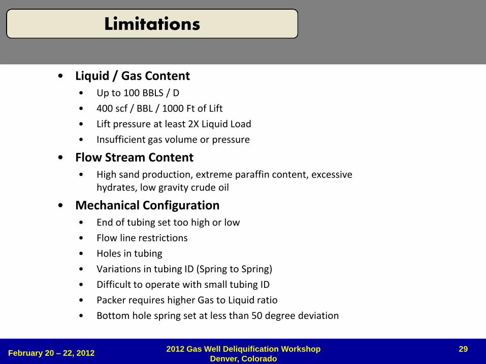
• Liquid / Gas Content • Up to 100 BBLS / D
• 400 scf / BBL / 1000 Ft of Lift
• Lift pressure at least 2X Liquid Load
• Insufficient gas volume or pressure
• Flow Stream Content • High sand production, extreme paraffin content, excessive
hydrates, low gravity crude oil
• Mechanical Configuration • End of tubing set too high or low
• Flow line restrictions
• Holes in tubing
• Variations in tubing ID (Spring to Spring)
• Difficult to operate with small tubing ID
• Packer requires higher Gas to Liquid ratio
• Bottom hole spring set at less than 50 degree deviation
February 20 – 22, 2012 2012 Gas Well Deliquification Workshop
Denver, Colorado
Limitations
30
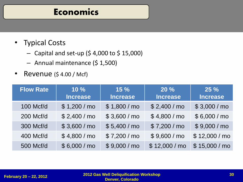
• Typical Costs – Capital and set-up ($ 4,000 to $ 15,000)
– Annual maintenance ($ 1,500)
• Revenue ($ 4.00 / Mcf)
Flow Rate 10 %
Increase
15 %
Increase
20 %
Increase
25 %
Increase
100 Mcf/d $ 1,200 / mo $ 1,800 / mo $ 2,400 / mo $ 3,000 / mo
200 Mcf/d $ 2,400 / mo $ 3,600 / mo $ 4,800 / mo $ 6,000 / mo
300 Mcf/d $ 3,600 / mo $ 5,400 / mo $ 7,200 / mo $ 9,000 / mo
400 Mcf/d $ 4,800 / mo $ 7,200 / mo $ 9,600 / mo $ 12,000 / mo
500 Mcf/d $ 6,000 / mo $ 9,000 / mo $ 12,000 / mo $ 15,000 / mo
February 20 – 22, 2012 2012 Gas Well Deliquification Workshop
Denver, Colorado
Economics
31 February 20 – 22, 2012
2012 Gas Well Deliquification Workshop
Denver, Colorado
KEY COMPONENTS
32
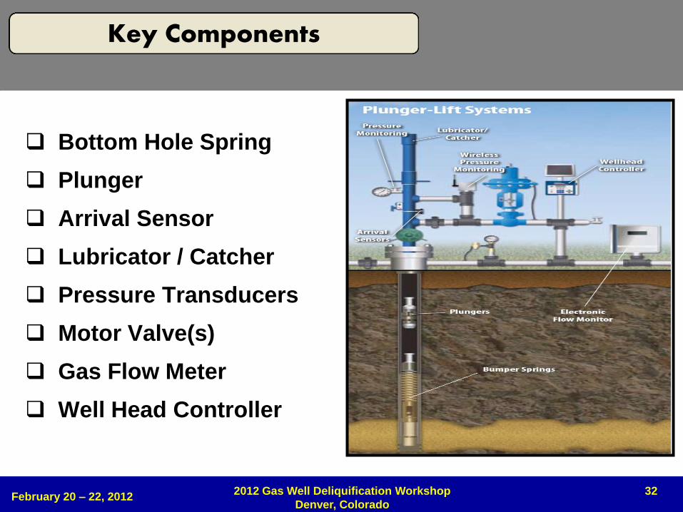
Bottom Hole Spring
Plunger
Arrival Sensor
Lubricator / Catcher
Pressure Transducers
Motor Valve(s)
Gas Flow Meter
Well Head Controller
February 20 – 22, 2012 2012 Gas Well Deliquification Workshop
Denver, Colorado
Key Components
33
1 2 3 4 5
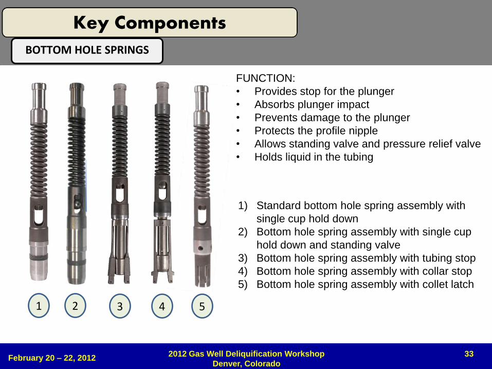
FUNCTION:
• Provides stop for the plunger
• Absorbs plunger impact
• Prevents damage to the plunger
• Protects the profile nipple
• Allows standing valve and pressure relief valve
• Holds liquid in the tubing
1) Standard bottom hole spring assembly with
single cup hold down
2) Bottom hole spring assembly with single cup
hold down and standing valve
3) Bottom hole spring assembly with tubing stop
4) Bottom hole spring assembly with collar stop
5) Bottom hole spring assembly with collet latch
BOTTOM HOLE SPRINGS
February 20 – 22, 2012 2012 Gas Well Deliquification Workshop
Denver, Colorado
Key Components
34
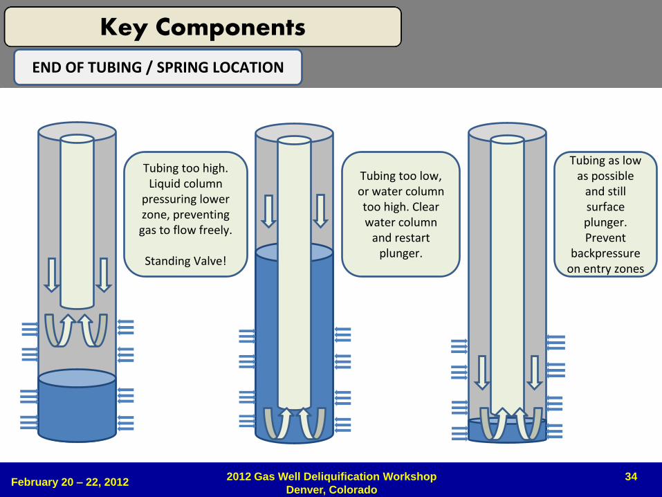
Tubing too high. Liquid column
pressuring lower zone, preventing gas to flow freely.
Standing Valve!
Tubing too low, or water column too high. Clear water column
and restart plunger.
Tubing as low as possible
and still surface plunger. Prevent
backpressure on entry zones
END OF TUBING / SPRING LOCATION
February 20 – 22, 2012 2012 Gas Well Deliquification Workshop
Denver, Colorado
Key Components
35 February 20 – 22, 2012
2012 Gas Well Deliquification Workshop
Denver, Colorado
Prepared by: Churchill
Date: 1/27/2008
GL = 742 ft
KB = 763 ft
API# 42-251-32044
Current
BISD B 2H
Newark East Field - Barnett Shale
Johnson County, Texas
Spud Date: 09/13/2007
Rig Release: 10/04/2007
Days to Drill: 21
Drilling Rig: UNION 216
Completion Date:
TD - 9355 ft MD / 7355 ft TVD
Surface Casing
9 5/8" 36/40 lb/ft J-55 ST&C
Setting Depth - 1494 ft
Float Shoe - 1.4 ft
Shoe Joint(s) - 38.22 ft
Float Collar - 1.2 ft
Cement
Lead - 375 sx Class C
Tail - 115 sx Class C
Production Casing
5 1/2" 17 lb/ft N-80 LT&C/Buttress
Setting Depth - 9355 ft
Float Shoe - 1.5 ft
Shoe Joint(s) - 44.72 ft
Float Collar - 1.5 ft
Marker Joint - 7293 ft (top) (15.38 ft)
Cement
Lead - 100 sx 50/50 POZ Class H
Tail - 640 sx 50/50 POZ Class H
Depth to FC - 9307 ft MD / 7356 ft TVD
Directional Information
+/- 50 deg deviaton - 7466 ft MD / 7271 ft TVD
Landing Pt. (+/- 90 deg) - 7719 ft MD / 7372 ft TVDLength of Lateral - 1513 ft
Completed Lateral Length - 1524 ft
# of Stages - 4
Stage Length - 381 ft (Completed Lateral Average)
Proposed Perf Spacing - 57
Perf Clusters - 6
Fully Cemented Lateral
Stage 1 - 6 spf 60 deg phasing
8,991 - 8,992
9,049 - 9,050
9,107 - 9,108
9,165 - 9,166
9,223 - 9,224
9,281 - 9,282
Total Holes - 36
Stage 2 - 6 spf 60 deg phasing
8,580 - 8,581
8,638 - 8,639
8,696 - 8,697
8,754 - 8,755
8,812 - 8,813
8,870 - 8,871
Total Holes - 36
Frac - Stage 1
Acid - 15% HCL = 4,000 Gal
Fresh H2O = 15,379 Bbl
100 Mesh = 379,500 Lbs
40/70 Sand = 49,980 Lbs
Total Sand = 429,480 Lbs
AIR = 74 bpm
ATP = 4,911 psi
Initial FG = 0.00 psi/ft
Final FG = 0.73 psi/ft
Frac - Stage 2
Acid - 15% HCL = 4,032 Gal
Fresh H2O = 15,697 Bbl
100 Mesh = 378,440 Lbs
40/70 Sand = 47,640 Lbs
Total Prop = 426,080 Lbs
AIR = 76 bpm
ATP = 5,100 psi
Initial FG = 0.00 psi/ft
Final FG = 0.76 psi/ft
Frac - Stage 3
Acid - 15% HCL = 4,032 Gal
Fresh H2O = 15,709 Bbl
100 Mesh = 379,620 Lbs
40/70 Sand = 47,180 Lbs
Total Prop = 426,800 Lbs
AIR = 76 bpm
ATP = 4,700 psi
Initial FG = 0.00 psi/ft
Final FG = 0.81 psi/ft
Frac - Stage 4
Acid - 15% HCL = 4,032 Gal
Fresh H2O = 15,221 Bbl
100 Mesh = 380,640 Lbs
40/70 Sand = 49,220 Lbs
Total Prop = 429,860 Lbs
AIR = 75 bpm
ATP = 5,100 psi
Initial FG = 0.00 psi/ft
Final FG = 0.83 psi/ft
Stage 3 - 6 spf 60 deg phasing
8,169 - 8,170
8,227 - 8,228
8,285 - 8,286
8,343 - 8,344
8,401 - 8,402
8,459 - 8,460
Total Holes - 36
Stage 4 - 6 spf 60 deg phasing
7,758 - 7,759
7,816 - 7,817
7,874 - 7,875
7,932 - 7,933
7,990 - 7,991
8,048 - 8,049
Total Holes - 36
Key Completion Indicators
Completion Date - 01/28/2008
Completed Length = 1,524 ft
Stage Length = 381 ft
Sand Load = 1,124 lb/ft
Water Load = 41 bbl/ft
Sand Concentration = 28 Lb/bbl
Total Water Load - 62,006 bbls
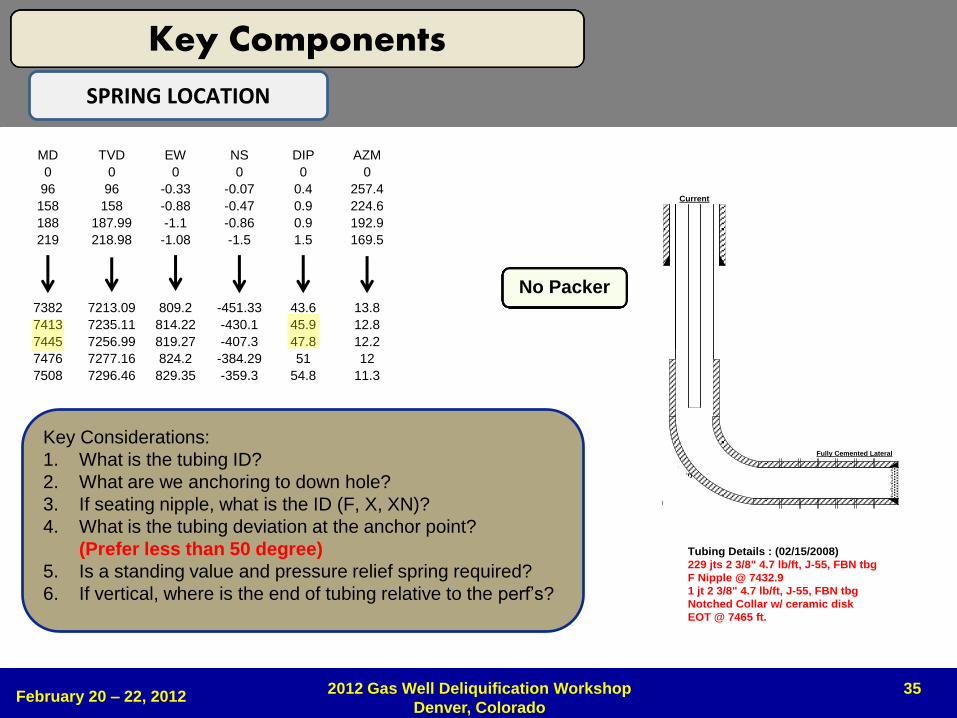
Tubing Details : (02/15/2008)
229 jts 2 3/8" 4.7 lb/ft, J-55, FBN tbg
F Nipple @ 7432.9
1 jt 2 3/8" 4.7 lb/ft, J-55, FBN tbg
Notched Collar w/ ceramic disk
EOT @ 7465 ft.
MD TVD EW NS DIP AZM
0 0 0 0 0 0
96 96 -0.33 -0.07 0.4 257.4
158 158 -0.88 -0.47 0.9 224.6
188 187.99 -1.1 -0.86 0.9 192.9
219 218.98 -1.08 -1.5 1.5 169.5
7382 7213.09 809.2 -451.33 43.6 13.8
7413 7235.11 814.22 -430.1 45.9 12.8
7445 7256.99 819.27 -407.3 47.8 12.2
7476 7277.16 824.2 -384.29 51 12
7508 7296.46 829.35 -359.3 54.8 11.3
7539 7313.41 834.27 -333.82 58.9 10.6
No Packer
Prepared by: Churchill
Date: 1/27/2008
GL = 742 ft
KB = 763 ft
API# 42-251-32044
Current
BISD B 2H
Newark East Field - Barnett Shale
Johnson County, Texas
Spud Date: 09/13/2007
Rig Release: 10/04/2007
Days to Drill: 21
Drilling Rig: UNION 216
Completion Date:
TD - 9355 ft MD / 7355 ft TVD
Surface Casing
9 5/8" 36/40 lb/ft J-55 ST&C
Setting Depth - 1494 ft
Float Shoe - 1.4 ft
Shoe Joint(s) - 38.22 ft
Float Collar - 1.2 ft
Cement
Lead - 375 sx Class C
Tail - 115 sx Class C
Production Casing
5 1/2" 17 lb/ft N-80 LT&C/Buttress
Setting Depth - 9355 ft
Float Shoe - 1.5 ft
Shoe Joint(s) - 44.72 ft
Float Collar - 1.5 ft
Marker Joint - 7293 ft (top) (15.38 ft)
Cement
Lead - 100 sx 50/50 POZ Class H
Tail - 640 sx 50/50 POZ Class H
Depth to FC - 9307 ft MD / 7356 ft TVD
Directional Information
+/- 50 deg deviaton - 7466 ft MD / 7271 ft TVD
Landing Pt. (+/- 90 deg) - 7719 ft MD / 7372 ft TVDLength of Lateral - 1513 ft
Completed Lateral Length - 1524 ft
# of Stages - 4
Stage Length - 381 ft (Completed Lateral Average)
Proposed Perf Spacing - 57
Perf Clusters - 6
Fully Cemented Lateral
Stage 1 - 6 spf 60 deg phasing
8,991 - 8,992
9,049 - 9,050
9,107 - 9,108
9,165 - 9,166
9,223 - 9,224
9,281 - 9,282
Total Holes - 36
Stage 2 - 6 spf 60 deg phasing
8,580 - 8,581
8,638 - 8,639
8,696 - 8,697
8,754 - 8,755
8,812 - 8,813
8,870 - 8,871
Total Holes - 36
Frac - Stage 1
Acid - 15% HCL = 4,000 Gal
Fresh H2O = 15,379 Bbl
100 Mesh = 379,500 Lbs
40/70 Sand = 49,980 Lbs
Total Sand = 429,480 Lbs
AIR = 74 bpm
ATP = 4,911 psi
Initial FG = 0.00 psi/ft
Final FG = 0.73 psi/ft
Frac - Stage 2
Acid - 15% HCL = 4,032 Gal
Fresh H2O = 15,697 Bbl
100 Mesh = 378,440 Lbs
40/70 Sand = 47,640 Lbs
Total Prop = 426,080 Lbs
AIR = 76 bpm
ATP = 5,100 psi
Initial FG = 0.00 psi/ft
Final FG = 0.76 psi/ft
Frac - Stage 3
Acid - 15% HCL = 4,032 Gal
Fresh H2O = 15,709 Bbl
100 Mesh = 379,620 Lbs
40/70 Sand = 47,180 Lbs
Total Prop = 426,800 Lbs
AIR = 76 bpm
ATP = 4,700 psi
Initial FG = 0.00 psi/ft
Final FG = 0.81 psi/ft
Frac - Stage 4
Acid - 15% HCL = 4,032 Gal
Fresh H2O = 15,221 Bbl
100 Mesh = 380,640 Lbs
40/70 Sand = 49,220 Lbs
Total Prop = 429,860 Lbs
AIR = 75 bpm
ATP = 5,100 psi
Initial FG = 0.00 psi/ft
Final FG = 0.83 psi/ft
Stage 3 - 6 spf 60 deg phasing
8,169 - 8,170
8,227 - 8,228
8,285 - 8,286
8,343 - 8,344
8,401 - 8,402
8,459 - 8,460
Total Holes - 36
Stage 4 - 6 spf 60 deg phasing
7,758 - 7,759
7,816 - 7,817
7,874 - 7,875
7,932 - 7,933
7,990 - 7,991
8,048 - 8,049
Total Holes - 36
Key Completion Indicators
Completion Date - 01/28/2008
Completed Length = 1,524 ft
Stage Length = 381 ft
Sand Load = 1,124 lb/ft
Water Load = 41 bbl/ft
Sand Concentration = 28 Lb/bbl
Total Water Load - 62,006 bbls
Tubing Details : (02/15/2008)
229 jts 2 3/8" 4.7 lb/ft, J-55, FBN tbg
F Nipple @ 7432.9
1 jt 2 3/8" 4.7 lb/ft, J-55, FBN tbg
Notched Collar w/ ceramic disk
EOT @ 7465 ft.
SPRING LOCATION
Key Considerations:
1. What is the tubing ID?
2. What are we anchoring to down hole?
3. If seating nipple, what is the ID (F, X, XN)?
4. What is the tubing deviation at the anchor point?
(Prefer less than 50 degree)
5. Is a standing value and pressure relief spring required?
6. If vertical, where is the end of tubing relative to the perf’s?
Key Components
36
0
50
100
150
200
250
300
0
50
100
150
200
250
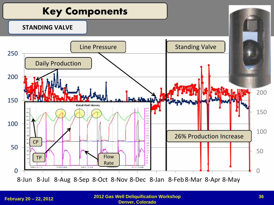
8-Jun 8-Jul 8-Aug 8-Sep 8-Oct 8-Nov 8-Dec 8-Jan 8-Feb 8-Mar 8-Apr 8-May
Standing Valve
26% Production Increase
Line Pressure
Daily Production
CP
TP Flow Rate
February 20 – 22, 2012 2012 Gas Well Deliquification Workshop
Denver, Colorado
STANDING VALVE
Key Components
37
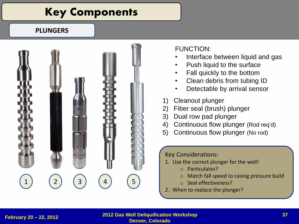
FUNCTION:
• Interface between liquid and gas
• Push liquid to the surface
• Fall quickly to the bottom
• Clean debris from tubing ID
• Detectable by arrival sensor
1) Cleanout plunger
2) Fiber seal (brush) plunger
3) Dual row pad plunger
4) Continuous flow plunger (Rod req’d)
5) Continuous flow plunger (No rod)
2 3 4 5 1
February 20 – 22, 2012 2012 Gas Well Deliquification Workshop
Denver, Colorado
PLUNGERS
Key Considerations: 1. Use the correct plunger for the well!
o Particulates? o Match fall speed to casing pressure build o Seal effectiveness?
2. When to replace the plunger?
Key Components
38 February 20 – 22, 2012
2012 Gas Well Deliquification Workshop
Denver, Colorado
PLUNGERS
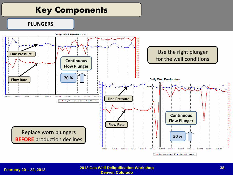
50 %
Continuous Flow Plunger
70 %
Use the right plunger for the well conditions
Replace worn plungers BEFORE production declines
Flow Rate
Line Pressure
Flow Rate
Line Pressure
Key Components
Continuous Flow Plunger
39
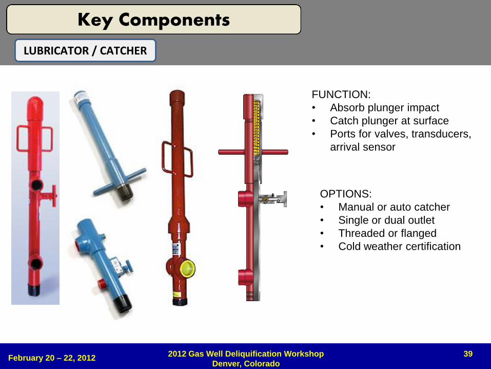
FUNCTION:
• Absorb plunger impact
• Catch plunger at surface
• Ports for valves, transducers,
arrival sensor
OPTIONS:
• Manual or auto catcher
• Single or dual outlet
• Threaded or flanged
• Cold weather certification
February 20 – 22, 2012 2012 Gas Well Deliquification Workshop
Denver, Colorado
LUBRICATOR / CATCHER
Key Components
40
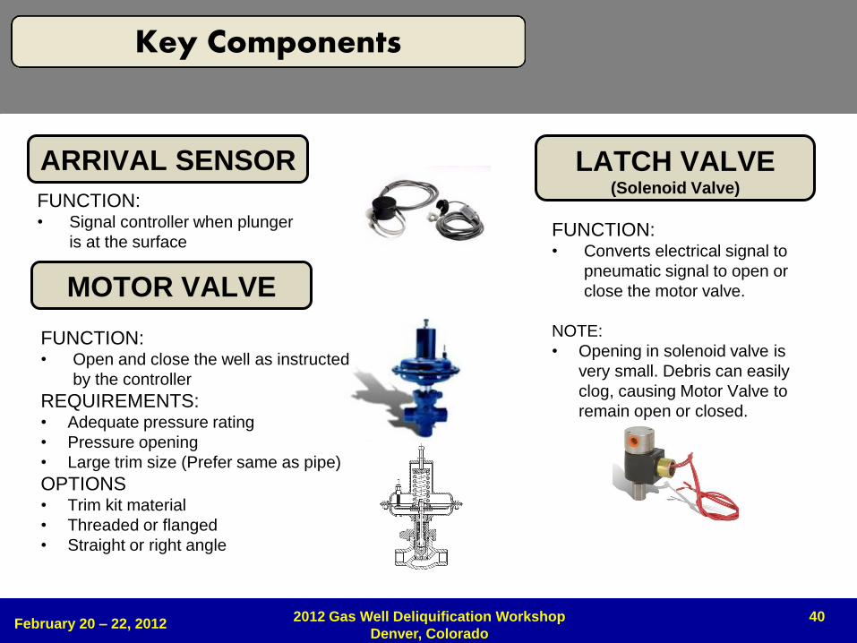
ARRIVAL SENSOR
FUNCTION: • Signal controller when plunger
is at the surface
MOTOR VALVE
FUNCTION: • Open and close the well as instructed
by the controller
REQUIREMENTS: • Adequate pressure rating
• Pressure opening
• Large trim size (Prefer same as pipe)
OPTIONS • Trim kit material
• Threaded or flanged
• Straight or right angle
LATCH VALVE (Solenoid Valve)
FUNCTION: • Converts electrical signal to
pneumatic signal to open or
close the motor valve.
NOTE:
• Opening in solenoid valve is
very small. Debris can easily
clog, causing Motor Valve to
remain open or closed.
February 20 – 22, 2012 2012 Gas Well Deliquification Workshop
Denver, Colorado
Key Components
41 February 20 – 22, 2012
2012 Gas Well Deliquification Workshop
Denver, Colorado
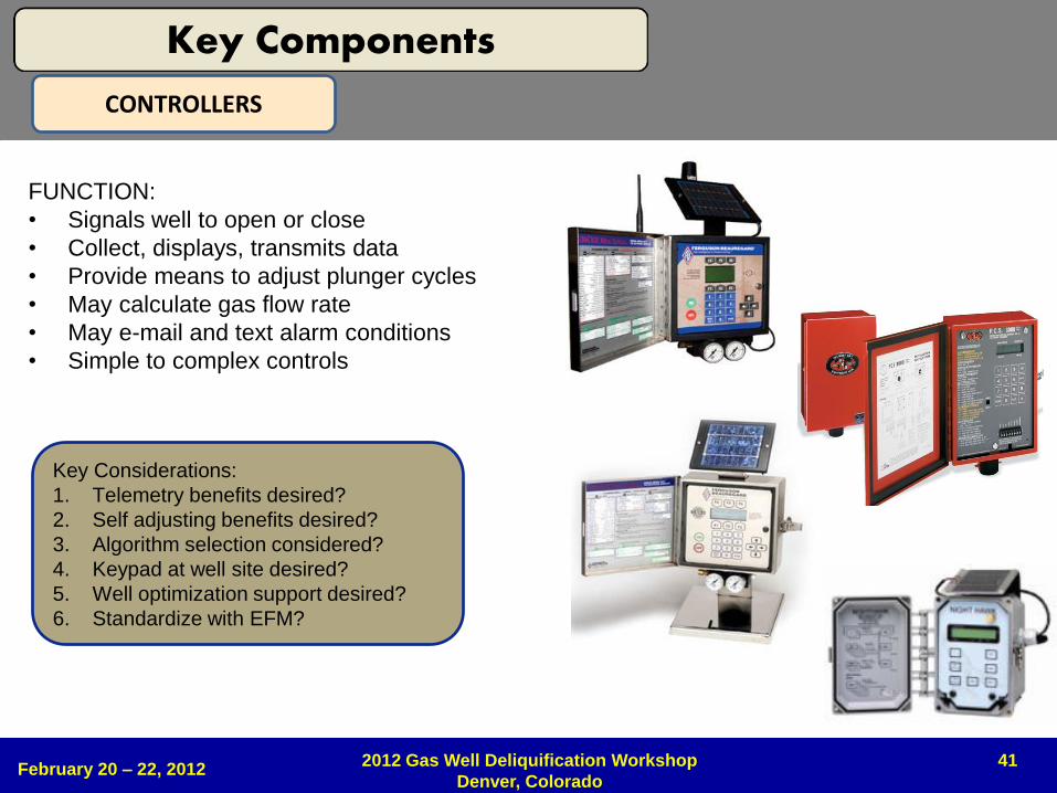
CONTROLLERS
FUNCTION:
• Signals well to open or close
• Collect, displays, transmits data
• Provide means to adjust plunger cycles
• May calculate gas flow rate
• May e-mail and text alarm conditions
• Simple to complex controls
Key Considerations:
1. Telemetry benefits desired?
2. Self adjusting benefits desired?
3. Algorithm selection considered?
4. Keypad at well site desired?
5. Well optimization support desired?
6. Standardize with EFM?
Key Components
42 February 20 – 22, 2012
2012 Gas Well Deliquification Workshop
Denver, Colorado
OPTIMIZE AND TROUBLESHOOT
43 February 20 – 22, 2012
2012 Gas Well Deliquification Workshop
Denver, Colorado
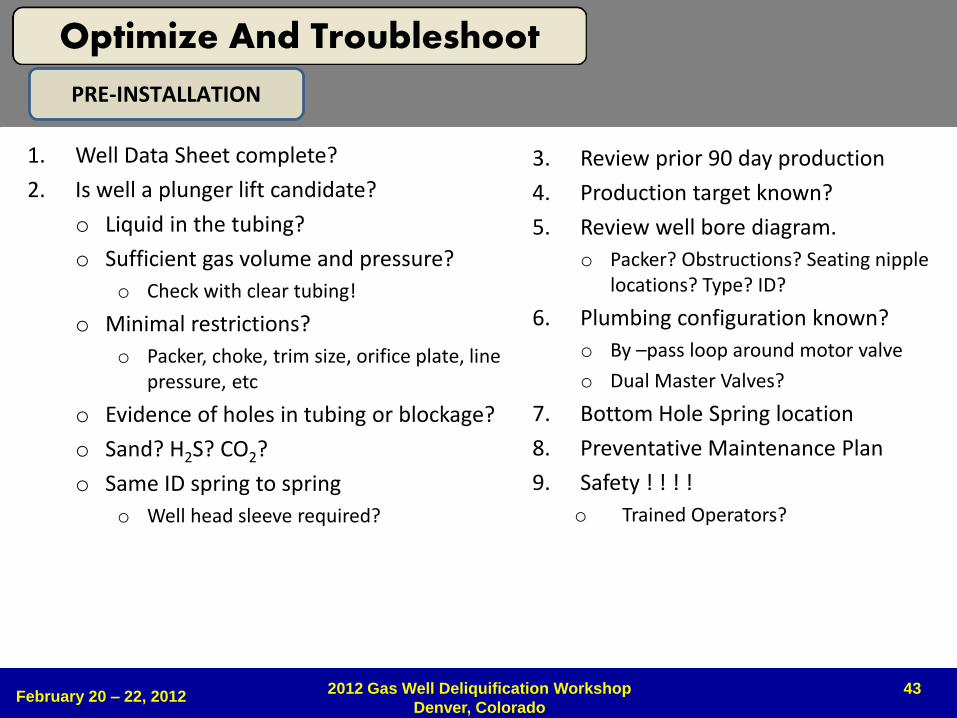
PRE-INSTALLATION
1. Well Data Sheet complete?
2. Is well a plunger lift candidate?
o Liquid in the tubing?
o Sufficient gas volume and pressure?
o Check with clear tubing!
o Minimal restrictions?
o Packer, choke, trim size, orifice plate, line pressure, etc
o Evidence of holes in tubing or blockage?
o Sand? H2S? CO2?
o Same ID spring to spring
o Well head sleeve required?
3. Review prior 90 day production
4. Production target known?
5. Review well bore diagram.
o Packer? Obstructions? Seating nipple locations? Type? ID?
6. Plumbing configuration known?
o By –pass loop around motor valve
o Dual Master Valves?
7. Bottom Hole Spring location
8. Preventative Maintenance Plan
9. Safety ! ! ! !
o Trained Operators?
Optimize And Troubleshoot
44
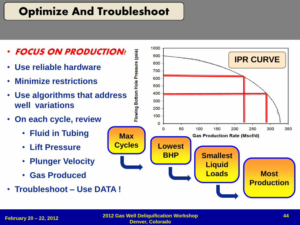
• FOCUS ON PRODUCTION!
• Use reliable hardware
• Minimize restrictions
• Use algorithms that address
well variations
• On each cycle, review
• Fluid in Tubing
• Lift Pressure
• Plunger Velocity
• Gas Produced
• Troubleshoot – Use DATA !
IPR CURVE
Max
Cycles
Smallest
Liquid
Loads
Lowest
BHP
Most
Production
February 20 – 22, 2012 2012 Gas Well Deliquification Workshop
Denver, Colorado
Optimize And Troubleshoot
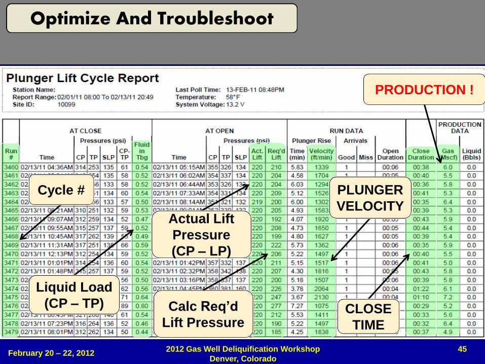
45
Liquid Load
(CP – TP)
Actual Lift
Pressure
(CP – LP)
PLUNGER
VELOCITY
Cycle #
CLOSE
TIME
Calc Req’d
Lift Pressure
PRODUCTION !
February 20 – 22, 2012 2012 Gas Well Deliquification Workshop
Denver, Colorado
Optimize And Troubleshoot
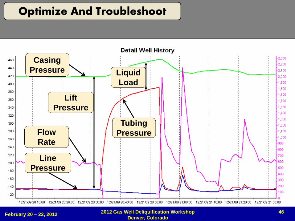
46
Line
Pressure
Lift
Pressure
Flow
Rate
Casing
Pressure
Tubing
Pressure
Liquid
Load
February 20 – 22, 2012 2012 Gas Well Deliquification Workshop
Denver, Colorado
Optimize And Troubleshoot
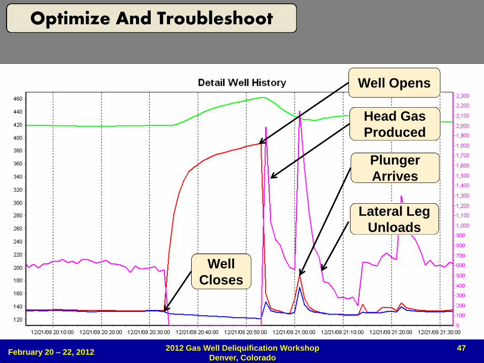
47
Well
Closes
Well Opens
Head Gas
Produced
Plunger
Arrives
Lateral Leg
Unloads
February 20 – 22, 2012 2012 Gas Well Deliquification Workshop
Denver, Colorado
Optimize And Troubleshoot
48 February 20 – 22, 2012
2012 Gas Well Deliquification Workshop
Denver, Colorado
SAFETY
• Arrive at site safely
– Avoid driving distractions. Drive courteously !
• Job Safety Analysis (www.osha.gov)
– Identify the sequence of steps to complete the job
– Identify hazards or potential hazards for each step
– Identify every possible source of energy
– Determine necessary actions to eliminate, control, or minimize hazards!
– Each safe job procedure or action must correspond to the job steps and identified hazards
• Wear appropriate Personal Protective Equipment !
February 20 - 22, 2012 2012 Gas Well Deliquification Workshop Denver, Colorado
49
Safety
50
• Injury – A technician was seriously injured when an unsuspected ice plug in the
wellhead lubricator released and struck the worker in the head resulting in a fractured skull and permanent eye loss.
• Contributing factors (partial list): – Ice build up in the lubricator assembly
– The ice build up in the lubricator was caused by produced water freezing in the assembly and no method of thawing the wellhead was available at this particular work site.
– Poor procedures in identifying potential hazards.
– Lack of operator training in safe work practices for the use of this equipment.
February 20 – 22, 2012 2012 Gas Well Deliquification Workshop
Denver, Colorado
Alberta Workplace Health and Safety Bulletin May 2007
51
• Noted sources of potential injury and equipment failure: – Removing lubricator cap with contained pressure above or below ice plugs,
sand bridges etc.
– Ice build up in the spring housing
– Paraffin, wax, sand and hydrates build up in the tubing string
– Poorly designed springs or stops
– Fast Plunger Arrivals • Plungers traveling “Dry” with little or no fluid
• Changes in line pressure, causing fast arrivals
• Change in plunger style used in well
– No methanol injection or heat trace to keep ice and hydrates from forming
February 20 – 22, 2012
2012 Gas Well Deliquification Workshop
Denver, Colorado
Alberta Workplace Health and Safety Bulletin May 2007
52
• Noted sources of potential injury and equipment failure: – Restricted flow path if the plunger is being held at surface causing a
pressure drop and creating the environment for the formation of hydrates
– Unexpected changes in flow regimes caused by cycling a plunger – sand production due to higher drawdown effect on the reservoir
– High pressure and volumes of gas and fluid affecting surface equipment due to the cyclic nature of plunger operations impact of the plunger at surface
February 20 – 22, 2012 2012 Gas Well Deliquification Workshop
Denver, Colorado
Alberta Workplace Health and Safety Bulletin May 2007
53
oBe Safe by Design !
What is your process ?
February 20 – 22, 2012 2012 Gas Well Deliquification Workshop
Denver, Colorado
Safety
54 February 20 – 22, 2012
2012 Gas Well Deliquification Workshop
Denver, Colorado
ADDENDUM
55 February 20 – 22, 2012
2012 Gas Well Deliquification Workshop
Denver, Colorado
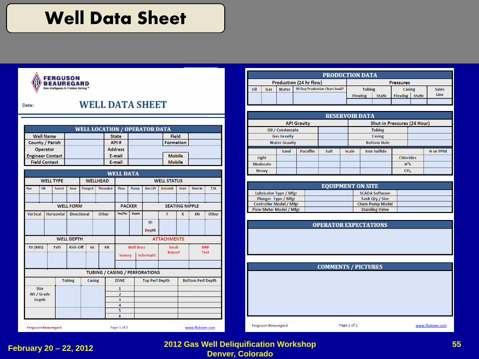
Well Data Sheet
56
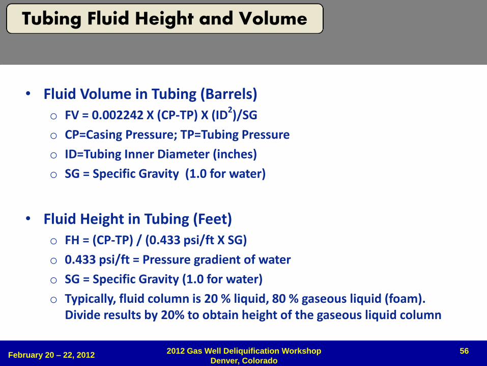
• Fluid Volume in Tubing (Barrels) o FV = 0.002242 X (CP-TP) X (ID2)/SG
o CP=Casing Pressure; TP=Tubing Pressure
o ID=Tubing Inner Diameter (inches)
o SG = Specific Gravity (1.0 for water)
• Fluid Height in Tubing (Feet) o FH = (CP-TP) / (0.433 psi/ft X SG)
o 0.433 psi/ft = Pressure gradient of water
o SG = Specific Gravity (1.0 for water)
o Typically, fluid column is 20 % liquid, 80 % gaseous liquid (foam). Divide results by 20% to obtain height of the gaseous liquid column
February 20 – 22, 2012 2012 Gas Well Deliquification Workshop
Denver, Colorado
Tubing Fluid Height and Volume
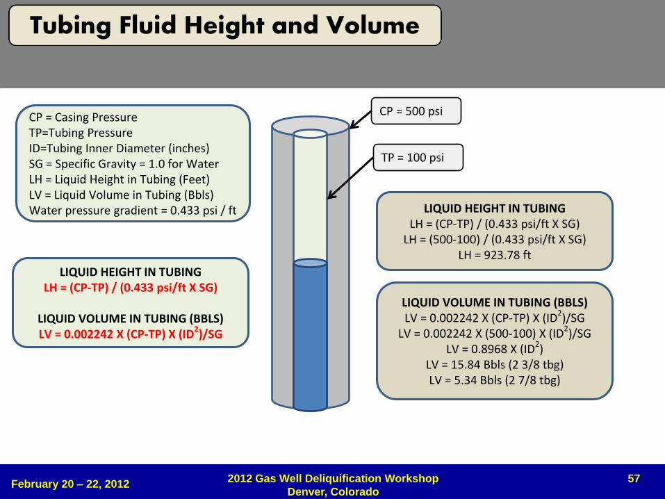
57
CP = Casing Pressure TP=Tubing Pressure ID=Tubing Inner Diameter (inches) SG = Specific Gravity = 1.0 for Water LH = Liquid Height in Tubing (Feet) LV = Liquid Volume in Tubing (Bbls) Water pressure gradient = 0.433 psi / ft
LIQUID HEIGHT IN TUBING LH = (CP-TP) / (0.433 psi/ft X SG)
LIQUID VOLUME IN TUBING (BBLS) LV = 0.002242 X (CP-TP) X (ID2)/SG
CP = 500 psi
TP = 100 psi
LIQUID HEIGHT IN TUBING LH = (CP-TP) / (0.433 psi/ft X SG)
LH = (500-100) / (0.433 psi/ft X SG) LH = 923.78 ft
LIQUID VOLUME IN TUBING (BBLS) LV = 0.002242 X (CP-TP) X (ID2)/SG
LV = 0.002242 X (500-100) X (ID2)/SG LV = 0.8968 X (ID2)
LV = 15.84 Bbls (2 3/8 tbg) LV = 5.34 Bbls (2 7/8 tbg)
February 20 – 22, 2012 2012 Gas Well Deliquification Workshop
Denver, Colorado
Tubing Fluid Height and Volume
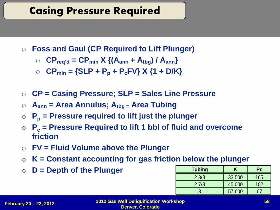
58
o Foss and Gaul (CP Required to Lift Plunger)
o CPreq’d = CPmin X {(Aann + Atbg) / Aann}
o CPmin = {SLP + Pp + PcFV} X {1 + D/K}
o CP = Casing Pressure; SLP = Sales Line Pressure
o Aann = Area Annulus; Atbg = Area Tubing
o Pp = Pressure required to lift just the plunger
o Pc = Pressure Required to lift 1 bbl of fluid and overcome
friction
o FV = Fluid Volume above the Plunger
o K = Constant accounting for gas friction below the plunger
o D = Depth of the Plunger K Pc
33,500 165
45,000 102
57,600 673
2 7/8
2 3/8
Tubing
February 20 – 22, 2012 2012 Gas Well Deliquification Workshop
Denver, Colorado
Casing Pressure Required
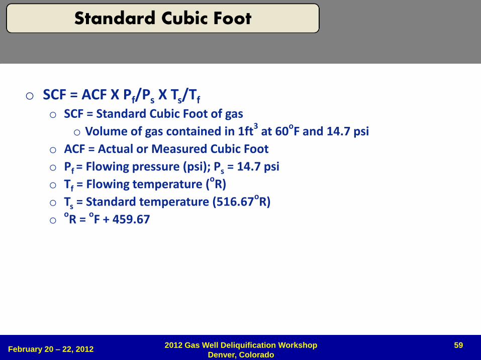
59
o SCF = ACF X Pf/Ps X Ts/Tf
o SCF = Standard Cubic Foot of gas
o Volume of gas contained in 1ft3 at 60oF and 14.7 psi
o ACF = Actual or Measured Cubic Foot
o Pf = Flowing pressure (psi); Ps = 14.7 psi
o Tf = Flowing temperature (oR)
o Ts = Standard temperature (516.67oR)
ooR = oF + 459.67
February 20 – 22, 2012 2012 Gas Well Deliquification Workshop
Denver, Colorado
Standard Cubic Foot
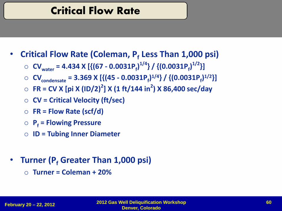
60
• Critical Flow Rate (Coleman, Pf Less Than 1,000 psi) o CVwater = 4.434 X [{(67 - 0.0031Pf)
1/4} / {(0.0031Pf)1/2}]
o CVcondensate = 3.369 X [{(45 - 0.0031Pf)1/4} / {(0.0031Pf)
1/2}]
o FR = CV X [pi X (ID/2)2] X (1 ft/144 in2) X 86,400 sec/day
o CV = Critical Velocity (ft/sec)
o FR = Flow Rate (scf/d)
o Pf = Flowing Pressure
o ID = Tubing Inner Diameter
• Turner (Pf Greater Than 1,000 psi) o Turner = Coleman + 20%
February 20 – 22, 2012 2012 Gas Well Deliquification Workshop
Denver, Colorado
Critical Flow Rate
61
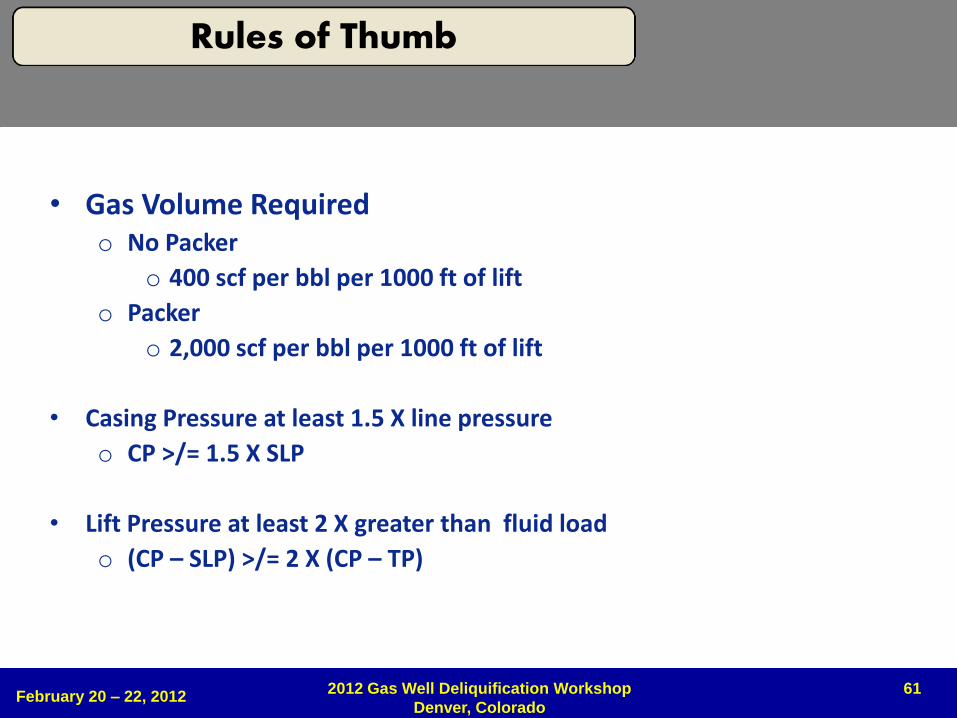
• Gas Volume Required o No Packer
o 400 scf per bbl per 1000 ft of lift
o Packer
o 2,000 scf per bbl per 1000 ft of lift
• Casing Pressure at least 1.5 X line pressure
o CP >/= 1.5 X SLP
• Lift Pressure at least 2 X greater than fluid load
o (CP – SLP) >/= 2 X (CP – TP)
February 20 – 22, 2012 2012 Gas Well Deliquification Workshop
Denver, Colorado
Rules of Thumb
62
Copyright
Rights to this presentation are owned by the company(ies) and/or author(s) listed on the title page. By submitting this presentation to the Gas Well Deliquification Workshop, they grant to the Workshop, the Artificial Lift Research and Development Council (ALRDC), and the Southwestern Petroleum Short Course (SWPSC), rights to:
– Display the presentation at the Workshop.
– Place it on the www.alrdc.com web site, with access to the site to be as directed by the Workshop Steering Committee.
– Place it on a CD for distribution and/or sale as directed by the Workshop Steering Committee.
Other use of this presentation is prohibited without the expressed written permission of the author(s). The owner company(ies) and/or author(s) may publish this material in other journals or magazines if they refer to the Gas Well Deliquification Workshop where it was first presented.
February 20 – 22, 2012
2012 Gas Well Deliquification Workshop
Denver, Colorado
63
Disclaimer
The following disclaimer shall be included as the last page of a Technical Presentation or Continuing Education Course. A similar disclaimer is included on the front page of the Gas Well Deliquification Web Site.
The Artificial Lift Research and Development Council and its officers and trustees, and the Gas Well Deliquification Workshop Steering Committee members, and their supporting organizations and companies (here-in-after referred to as the Sponsoring Organizations), and the author(s) of this Technical Presentation or Continuing Education Training Course and their company(ies), provide this presentation and/or training material at the Gas Well Deliquification Workshop "as is" without any warranty of any kind, express or implied, as to the accuracy of the information or the products or services referred to by any presenter (in so far as such warranties may be excluded under any relevant law) and these members and their companies will not be liable for unlawful actions and any losses or damage that may result from use of any presentation as a consequence of any inaccuracies in, or any omission from, the information which therein may be contained.
The views, opinions, and conclusions expressed in these presentations and/or training materials are those of the author and not necessarily those of the Sponsoring Organizations. The author is solely responsible for the content of the materials.
The Sponsoring Organizations cannot and do not warrant the accuracy of these documents beyond the source documents, although we do make every attempt to work from authoritative sources. The Sponsoring Organizations provide these presentations and/or training materials as a service. The Sponsoring Organizations make no representations or warranties, express or implied, with respect to the presentations and/or training materials, or any part thereof, including any warrantees of title, non-infringement of copyright or patent rights of others, merchantability, or fitness or suitability for any purpose.
February 20 – 22, 2012 2012 Gas Well Deliquification Workshop
Denver, Colorado