Embed Size (px)
Citation preview
The Second International Conference onSustainable Infrastructure and Built Environment (SIBE-2013)Bandung, Indonesia – November 19th – 20th 2013
A 3-Dimensional Numerical Study of Flow Patterns aroundThree Types of Drop Spillway
Dantje K. Natakusumah1, Dhemi Harlan 2, Fitra Adinata3, Waluyo Hatmoko4, AdeKhairani Tobing5, Muhammad Juangga6 dan M. Rizki Kusmaryadi7
1,2Water Resources Engineering Research Group, Institute of Technology Bandung3PT Sapta Adhi Pratama, Bandung
4 Water Resources Research Center, Ministry of Public Works, Bandung5,6,7Water Resources Engineering Graduate Students, Institute of Technology Bandung
Email: [email protected]
Abstract. Traditionally the behaviors of hydraulic structures are studied usingscaled physical models constructed in hydraulic laboratories. In general theseapproaches are expensive, time-consuming and often subject to error due todifficulties associated with scaling effects. With the advance in computergraphics, computer technology and more efficient Computational FluidDynamics (CFD) algorithm, the behavior of hydraulic structures can now beinvestigated numerically in reasonable time and expense.
This paper describes the CFD modeling of three type of drop spillway in three-dimension. FLOW3D3 software which solves the Navier-Stokes equation by thefinite difference method, use the algorithm based on SOLA method while theVolume of Fluid (VOF) method was used for computing free surface motion. Inthis analysis FLOW3D was applied to numerically solve the Navier-Stokesequations for solution domains around three types of drop spillways each ofwhich is modeled into single region. Depending of complexity and the number ofgrid poits of the spillway model, numerical simulation by using FLOW3D onpersonal computer can takehours to a few days. Much shorter than scaledphysical models constructed in hydraulic laboratories
In this preliminary paper, the calculated results such as pressure, velocities, flowrate, surface height have not been validated against experimental data. The workon that direction is now underway. In conclusion, the results obtained usingnumericalmodel in terms of velocity patterns, local flow disturbances, dischargerate, surface height distribution and Froude number can be easily obtained forfurther used for engineering design purpose.
Keywords: Drop Spillway, FLOW3D, Numerical model, Hydraulics
1 Introduction
One of the main functions of the spillway is to pass water from a high elevationto low elevation place to lower one. Due to the elevation change, the potentialenergy turns into kinetic energy and directing the flow of water moving at acertain speed. Another function of the spillway is to reduce the kinetic energy ofwater through the spillway so that the speed at the end of spillway becomessmaller. Damping occurs either as a result of collisions with rigid bodies ofwater or due to collisions among the particles of water in the whirlpool, causingpartial loss of kinetic energy of the flow.
2 Dantje K. Natakusumah et.al
In conventional spillway energy dissipation took place in a horizontal direction,by the collision with vertical plane (e.g baffle piers) and resulting turbulence. Inthe conventional spillway, Water flow through the spillway crest and chutechannel, only relatively small energy is reduce by friction. However, uponentering the energy dissipator, the energy flow will be broken down by chuteblock and most of kinectic energy will be dissipate by baffle piers and waterturbulence. Finally the water flow will be levelled by end sill.
The initial idea for developing drop spillway studied in this research, startedfrom experience of the main author, when he design a detention pond located inLIPO Cikarang. At the outlet of detention pond a conventional WES spillway of16 meters crest lenght and 4 meters high and a USBR-III stilling basin has beenprepared for the contruction. Since the construction cost of the original designwas quite high, and the available land is limited, the original design wasreplaced with a new design, the drop spillway , we name it type I dropspillway, connected with the box culvert. This spillway can significantly reducethe construction costs and require much smaller space. Based on this success,some impovement and changes have been made, until we arive at the concept ofthe drop spillway I, T and U type.
2 Methodology
In this paper, we present some preliminary results on hydraulic characteristicstesting of 3 types of drop spillway known as drop spillway I-Type, T-Type andU-Type. This 3D numerical study was performed using FLOW3D software.FLOW-3D is a general-purpose computational fluid dynamics (CFD) software.FLOW3D is based on the Navier Stokes equations which consists of a three-dimensional continuity equation, momentum equation and energy equation 3-dimensional fluid.
Detailed description on how to solve the equation is beyond the scope of thispaper, and the interested reader is referred to the FLOW3D User technicalrefference [4]. However, it can be explained that FLOW3D employs speciallydeveloped numerical techniques to solve the equations of motion for fluids toobtain transient, three-dimensional solutions to multi-scale, multi-physics flowproblems. An array of physical and numerical options allows users to applyFLOW-3D to a wide variety of fluid flow and heat transfer phenomena.
The problem of flow with free of water surface is a particular challenge in 3Dnumerical models. The Volume of Fluid (VOF) method developed by Hirth [1]is employed in FLOW-3D for this purpose. It consists of three maincomponents: the definition of the volume of fluid function, a method to solvethe VOF transport equation and setting the boundary conditions at the freesurface.
Flow-3D using structured and orthogonal grid with a rectangular shape (2D)and hexahedral cells (3D). Calculation grid is fixed (non-adaptive) and do notmove during the process of calculation. Boundary between air and objectsdefined by the method of Fractional Area Volume Obstacle Representation(FAVOR). As surface of water moves, the grid will also move vertically.Therefore, only the water phase will be counted, not the air phase [2].
A 3-D Numerical
3 Results and Disscusion
In this paper, some preliminary results on numerical modeling of three dropspillway, known as drop spillwayspillway are intended for embung. Embung is local name for a small dam withwater stroring capacity less than 500 thousand mkm, embankment height less than 10 meters and it is built on firm soil and lowpermeability soil.
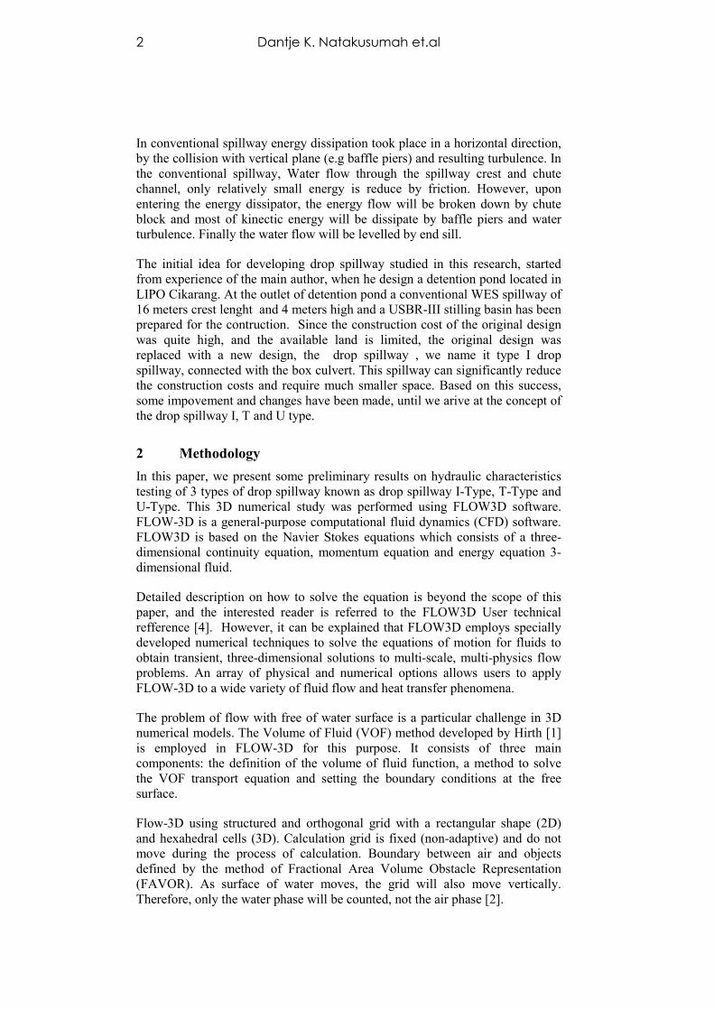
Figure 1 shows 3 types of drop spillwaysThese drop spillwayconstructed in two stages. Using stage construction, the costs of constructioncan be distributed in stage. It starts with low cost low height dam and whenaddional fund is available, the constructistop the operation of embung built in the earlier stage. According to theregulation, development of small embung like this, does not require damcertification process.
Figure 1: Perspective
Numerical Study of Three Types of Drop Spillway
Results and Disscusion
some preliminary results on numerical modeling of three dropspillway, known as drop spillway I-Type, T-Type and U-Type. These dropspillway are intended for embung. Embung is local name for a small dam withwater stroring capacity less than 500 thousand m3, dam crest lengt less than 1km, embankment height less than 10 meters and it is built on firm soil and low
3 types of drop spillways investigated in this researchpillway are planned to be built in conjuction of embung
constructed in two stages. Using stage construction, the costs of constructioncan be distributed in stage. It starts with low cost low height dam and whenaddional fund is available, the construction can be continue without having tostop the operation of embung built in the earlier stage. According to theregulation, development of small embung like this, does not require dam
Perspective View of Drop Spillway I-Type, T-Type and U-
Three Types of Drop Spillway 3
some preliminary results on numerical modeling of three drop. These drop
spillway are intended for embung. Embung is local name for a small dam with3, dam crest lengt less than 1
km, embankment height less than 10 meters and it is built on firm soil and low
in this research [3].are planned to be built in conjuction of embung
constructed in two stages. Using stage construction, the costs of constructioncan be distributed in stage. It starts with low cost low height dam and when
on can be continue without having tostop the operation of embung built in the earlier stage. According to theregulation, development of small embung like this, does not require dam
-Type
4 Dantje K. Natakusumah et.al
3.1 Drop Spillway I-Type
The first type of spillway modeled numerically using FLOW3D is I-Type dropspillway. The dam embankment is planned to be built in two stages, where inthe Stage-1, 5-meter embankment is constructed. At Stage -2, additional 5 meterembankment construted behind the stage-1 embankment. Development ofStage-1 to Stage -2 can be done without without having to stop the operation ofembung built in the earlier stage.
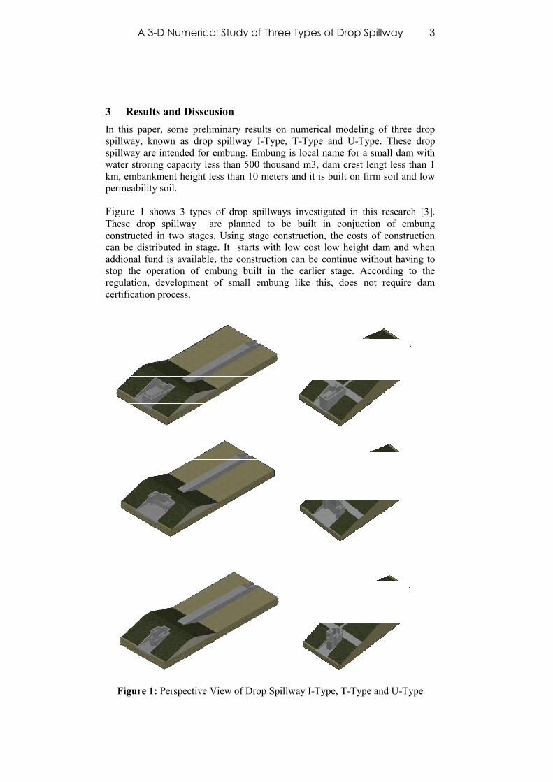
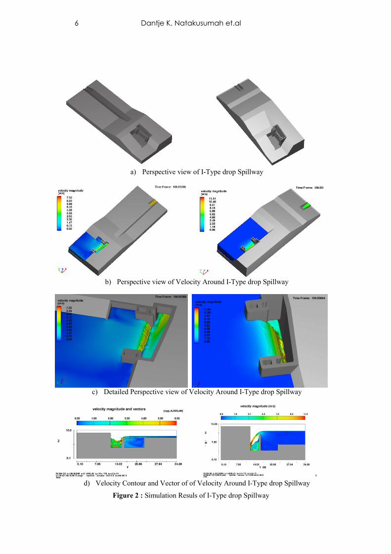
Perspective view of I-Type drop Spillway at the first and second stage areshown in figure Figure 2.a). Crest Lenght in both stages is 10.0 meter, butCrest Elevastion has ben raised from elevation +3.0 m to elevaton +7.0 m. Thefollowing results were obtained when flood dicharge of 20 m3/s pass over thespillway crest. Figure 2.b) shows perspective view of velocity around I-Typedrop spillway at the first and second stage. Figure 2.c) shows detailedperspective view of velocity around I-Type drop spillway at the first and secondstage. Figure 2.d) shows velocity contour and vector of of velocity around I-Type drop Spillway at the first and second stage. Finally a more detailed :Numerical Results of 3D Drop Spillway I-Type is given in Table 1.
Table 1 : Numerical Results of 3D Drop Spillway I-Type
No Computed Values Unit Stage-1 Stage -21 Discharge m3/s 20 202 Crest Lenght m 10 103 Crest Elevastion m +3.0 +7.04 Weter Level at the stilling basin m +0.0 +0.05 Weter Level at the reservoar m +7.66 + 11.946 Water Depth Above the Crest m 0.64 0.727 Velocity in the middle of the crest m/s 2.8 2.58 Velocity at the mid of stilling basin m/s 2.8 2.59 Weter Depth at mid the basin m 2.32 3.085
10 Velocity at the start Box Culvert m/s 4.39 2.211 Depth at the start Box Culvert m 2.32 3.08512 Velocity at the end Box Culvert m/s 6.95 5.25413 Depth at the end Box Culvert m 2.2 2.9
3.2 Drop Spillway T-Type
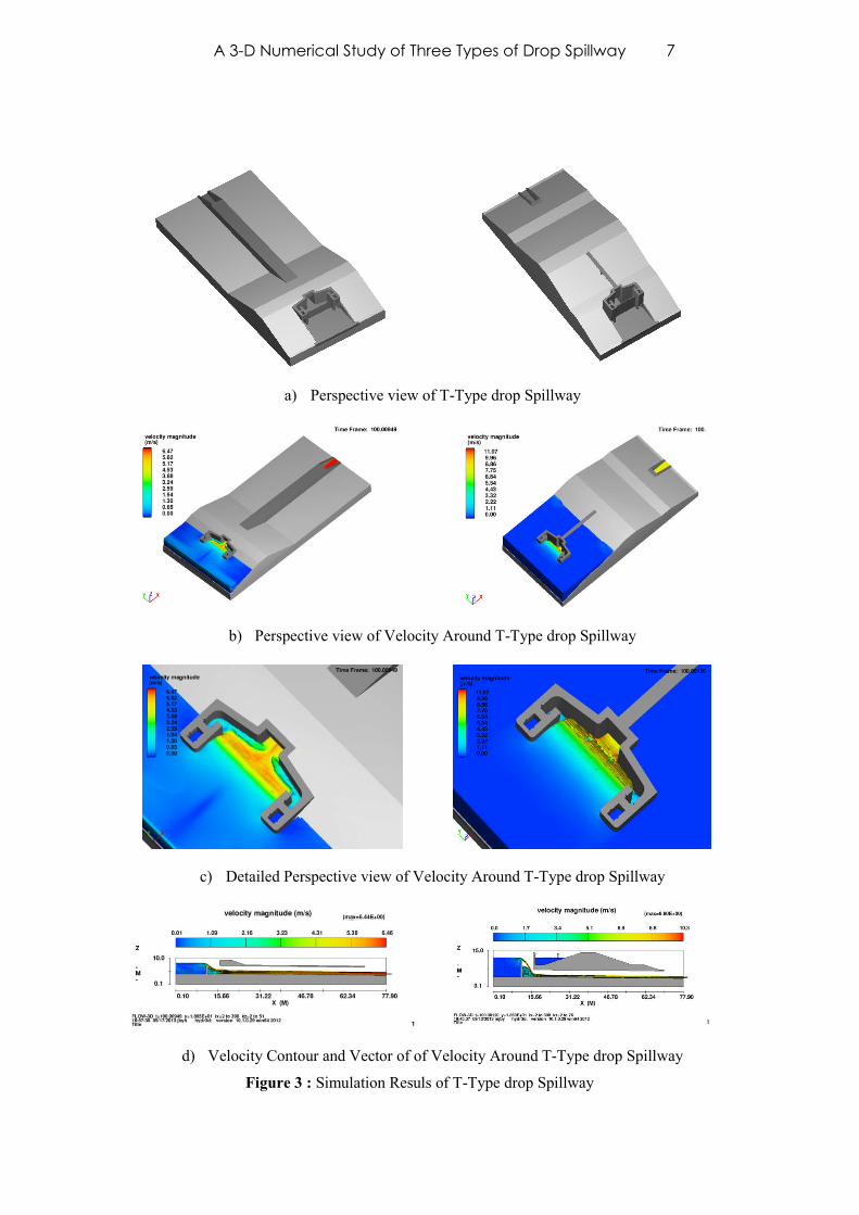
The Second type of spillway modeled numerically using FLOW3D software isT-Type drop spillway. Perspective view of T-Type drop Spillway at the firstand second stage are shown in figure Figure 3.a). Crest Lenght in both stages is10.0 meter, the crest Elevation of the spillway has ben raised from elevation+3.0 m to elevaton +7.0 m. The following results were obtained when flooddicharge of 20 m3/s pass over the spillway crest. Figure 3.b) shows perspectiveview of velocity around T-Type drop spillway at the first and second stage.Figure 3.c) shows detailed perspective view of velocity around T-Type dropspillway at the first and second stage. Finally Figure 3.d) shows velocitycontour and vector of of velocity around T-Type drop Spillway at the first andsecond stage. Finally a more detailed Numerical Results of 3D Drop Spillway I-Type is given in Table 2.
A 3-D Numerical Study of Three Types of Drop Spillway 5
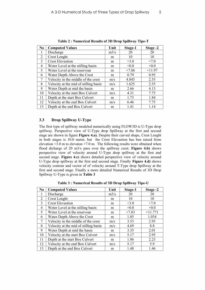
Table 2 : Numerical Results of 3D Drop Spillway Tipe-T
No Computed Values Unit Stage-1 Stage -21 Discharge m3/s 20 202 Crest Lenght m 10 103 Crest Elevastion m +3.0 +7.04 Weter Level at the stilling basin m +0.0 +0.05 Weter Level at the reservoar m +7.86 +11.976 Water Depth Above the Crest m 0.79 0.957 Velocity in the middle of the crest m/s 4.845 2.558 Velocity at the mid of stilling basin m/s 1.625 2.559 Weter Depth at mid the basin m 2.66 4.13
10 Velocity at the start Box Culvert m/s 4.31 7.7511 Depth at the start Box Culvert m 1.73 1.8412 Velocity at the end Box Culvert m/s 6.46 7.7513 Depth at the end Box Culvert m 1.41 1.14
3.3 Drop Spillway U-Type
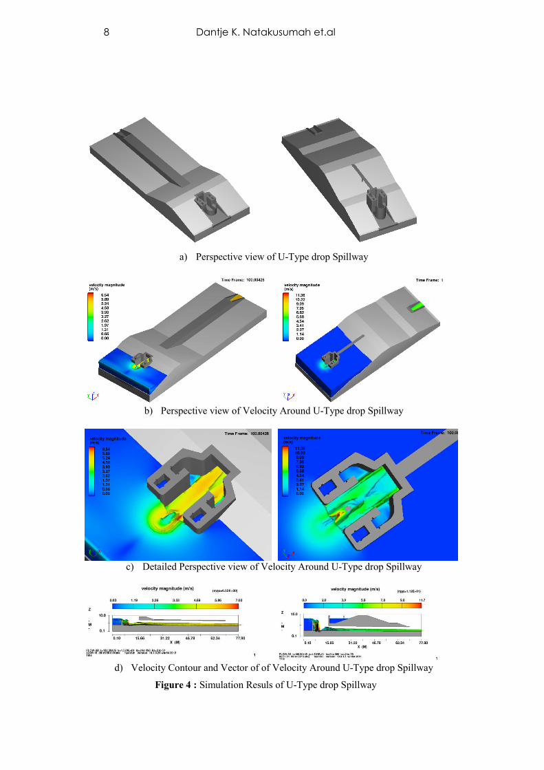
The first type of spillway modeled numerically using FLOW3D is U-Type dropspillway. Perspective view of U-Type drop Spillway at the first and secondstage are shown in figure Figure 4.a). Despite their curved shape, Crest Lenghtin both stages is 10.0 meter, but the Crest Elevastion has ben raised fromelevation +3.0 m to elevaton +7.0 m. The following results were obtained whenflood dicharge of 20 m3/s pass over the spillway crest. Figure 4.b) showsperspective view of velocity around U-Type drop spillway at the first andsecond stage. Figure 4.c) shows detailed perspective view of velocity aroundU-Type drop spillway at the first and second stage. Finally Figure 4.d) showsvelocity contour and vector of of velocity around T-Type drop Spillway at thefirst and second stage. Finally a more detailed Numerical Results of 3D DropSpillway U-Type is given in Table 3
Table 3 : Numerical Results of 3D Drop Spillway Tipe-U
No Computed Values Unit Stage-1 Stage -21 Discharge m3/s 20 202 Crest Lenght m 10 103 Crest Elevastion m +3.0 +7.04 Weter Level at the stilling basin m +0.0 +0.05 Weter Level at the reservoar m +7.83 +11.7716 Water Depth Above the Crest m 1.05 1.0347 Velocity in the middle of the crest m/s 3.53 2.958 Velocity at the mid of stilling basin m/s 4.69 8.89 Weter Depth at mid the basin m 3.35 2.01
10 Velocity at the start Box Culvert m/s 5.17 2.9511 Depth at the start Box Culvert m 1.86 2.2312 Velocity at the end Box Culvert m/s 5.17 5.913 Depth at the end Box Culvert m 1.48 1.46
6 Dantje K. Natakusumah et.al
a) Perspective view of I-Type drop Spillway
b) Perspective view of Velocity Around I-Type drop Spillway
c) Detailed Perspective view of Velocity Around I-Type drop Spillway
d) Velocity Contour and Vector of of Velocity Around I-Type drop Spillway
Figure 2 : Simulation Resuls of I-Type drop Spillway
A 3-D Numerical Study of Three Types of Drop Spillway 7
a) Perspective view of T-Type drop Spillway
b) Perspective view of Velocity Around T-Type drop Spillway
c) Detailed Perspective view of Velocity Around T-Type drop Spillway
d) Velocity Contour and Vector of of Velocity Around T-Type drop Spillway
Figure 3 : Simulation Resuls of T-Type drop Spillway
8 Dantje K. Natakusumah et.al
a) Perspective view of U-Type drop Spillway
b) Perspective view of Velocity Around U-Type drop Spillway
c) Detailed Perspective view of Velocity Around U-Type drop Spillway
d) Velocity Contour and Vector of of Velocity Around U-Type drop Spillway
Figure 4 : Simulation Resuls of U-Type drop Spillway
A 3-D Numerical Study of Three Types of Drop Spillway 9
4 Research Benefits
Small dam and dry detention pond both have almost similar shape, in the formof hollow ground which is usually a small river valley and dammed the buildingis equipped with spillway and outlet expenses can be arranged. Although smalldam and dry detention pond has almost the same shape, but they have differentfunctions.
Small dam function to save rainwater to be used for a variety of uses (e.g.agricultural, domestic or industrial). Thus the small dam is almost alwaysfilled with water and empty only if the water supply has been used up.Function as small dam of water-use and water conservation infrastructurefor various needs
Dry detention pond serves to hold the flood discharge of the river basin isrelatively small, with spending set saved flood water through the outlet canbe set in order for the downstream location of the dry detention pond areawas not flooded. Function is as a dry detention pond handling of destructiveforce of water infrastructure.
One benefit of this research can also be seen from the fact that many former pitcoal mines are scattered in various locations in East Kalimantan and SouthKalimantan. Besides the former tin mine often found in Bangka Belitungprovince, mined bauxite is also often found on the island of Bintan, Riau IslandsProvince. Conversion pits into ponds for water conservation will solve oneenvironmental problem arising after mining operations were closed. Utilizationof pits water can only be done if the water in the pit can be controlled.Controlling water in the former mines can only be done by deepening outletmined by digging or raise water by damming part of the land around the pitoutlet and then install the spillway and water level control.
Another benefit of this research can also be seen from the fact that manyresidential areas and industrial areas, frequently flooded due to lack ofinfrastructure gor controlling runoff. According to regulations, the developer isactually required to make flood control infrastructure, where one of them is aconventional reservoir. Conventional flood control infrastructure is not popular,because it takes a lot of areas and they cannot be used for other activities, sincethey filled with water.
To overcome the reluctance of developers to build a conventional detentionpond, recently developed a new idea to create a dry detention pond. When thereis no rain reservoar pool is not filled with water, or only slightly flooded, thusthe location of the dry detention pond can be used as a green area where themorning sports area taking place. When it rains, substantial portion reservoirpond will be filled with water, but they will gradually recede because the wateris gradually released through an outlet reservoir dry.
5 Conclusion
Simulation results on the drop spillway I-Type, T-Type and U-Type showsrealistic results. The results obtained were able to show the magnitude ofvelocity, thickness of water, turbulent energy and dissipation energy in almostall parts of spillway from upstream to downstream..
10 Dantje K. Natakusumah et.al
This kind of detailed results, althouh can still be obtained in the physical model,it will require much longer time, both to acquire the raw data and to process itinto a variable such as turbulent energy, energy dissipation and the Froudenumber that cannot be measured directly. The test results of drop spillway I-Type, T-Type and U-Type shows that the numerical model has its advantageswhich can give results much faster and relatively cheaper, the physical modelrequires a much longer time and are more expensive.
Spillway physical model testing needs to be done immediately for the mostpromising shape, according to the numerical results that will be performed atthe Laboratory of Physical Hydraulic Model Testing, Civil Engineering ITB.Currently physical models of the most promising forms are still in progress.
6 Acknowledgements
The authors express gratitude to Directorate General of Higher Education andresearch that has provided funding through the DIKTI Decentralization ofHigher Education Research Program 2013. The authors also express ourgratitude to the LPPM-ITB who had been monitoring the implementation of thestudy.
7 References
[1] C. W. Hirt And B. D. Nichols, Volume of Fluid (VOF) Method for theDynamics of Free Boundaries, Journal Of Computational Physics 39,201-225 (1981)
[2] Hossein Afshar, Seyed Hooman Hoseini, Experimental and 3-DNumerical Simulation of Flow over a Rectangular Broad-Crested Weir,International Journal of Engineering and Advanced Technology (IJEAT),ISSN: 2249 – 8958, Volume-2, Issue-6, August 2013
[3] Dantje K. Natakusumah,Pembuatan Protoptye, Pengujian Modek FisikDan Model Numerik Tiga Dimensi Untuk Pelimpah Terjunan Tipe I,Tipe T Dan Tipe U Serta Penggunaanya Pada Konstruksi Kolam TandonKering (Dry Detention Pond) Dan Konstruksi Embung (Small Dam,Proposal Riset Desentralisasi DIKTI, 2013).
[4] FLOW3D, User Manual, Flow Science, Inc, 2013.