Embed Size (px)
Citation preview
ALLEN-BRADLEY
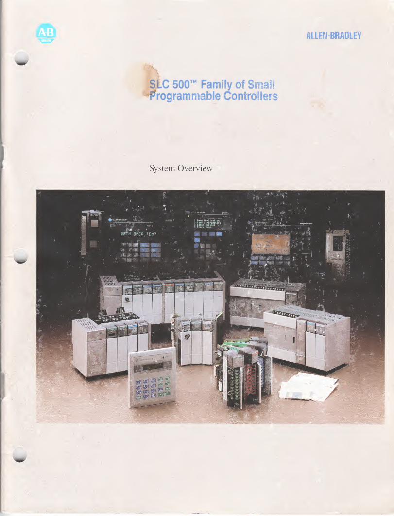
si.C 500™ Family of Small •Programmable Controllers
System Overview
Overview. 1
New Product Summary . 1
System Configuration. 2
SLC 500 Fixed Controller. 3
SLC 500 Modular Controller. 6
Power Supply Options. 9
1746 Discrete I/O Modules. 10
Specialty I/O Modules . 13
1746 I/O Analog Modules. 13
1746-NT4 Thermocouple/mV Module. 15
1746-HSCE High-Speed Counter Module. 17
1746- HS IMC 110 Servo Positioning Module. 18
Remote I/O Modules. 19
1747- SN Remote I/O Scanner. 19
1747-ASB Remote I/O Adapter Module. 20
1747-DCM Direct Communications Module. 21
1747-DSN Distributed I/O Scanner. 22
Remote I/O Devices. 23
Remote Communication . 24
1747-KE DH-485/RS-232C Interface Module. 24
1746- BAS BASIC Module and BASIC Development Software. 24
1770-KF3 DH-485 Communication Interface Module. 25
Networking Options. 26
1784-KR Personal Computer Interface Card . 26
6001-F2E Standard Driver. 27
1747— AIC Isolated Link Coupler for DH-485 Connection. 27
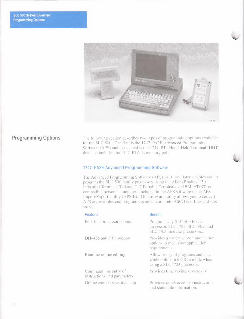
Programming Options. 28
1747-PA2E Advanced Programming Software. 28
1747-PIC Interface Converter Programming Options . 29
1747-PT1 Hand-Held Terminal . 30
Operator Interface. 31
1747-DTAM-E Data Table Access Module . 31
Bulletin 2707 DTAM Plus Operator Interface . 32
Support. 33
Configuring an SLC 500 System . 33
SLC 500 Chassis Configuration Instructions. 34
Fixed I/O Chassis Module Compatibility. 36
Instruction Set. 39
Fixed Wiring Diagrams. 40
Approximate Chassis Dimensions. 42
Available Cables . 44
SLC 500 System Overview
Overview
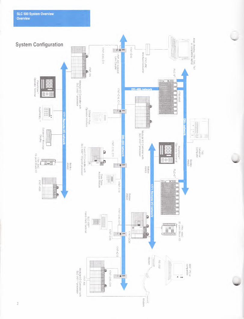
Overview The SLC 500 family gives you power and flexibility for a complete control solution. Its powerful processor instruction set, advanced programming tools, and expanded product capabilities give you all of the right reasons to use it for your next control application.
The SLC 500 family is a growing family of small programmable controllers built around two hardware options; a fixed controller with an option to expand using a 2-slot chassis, or a modular I/O controller with up to 960 I/O points. The programming tools and most I/O modules are compatible between the two hardware options, so you can cost effectively solve a broad range of applications.
In addition to configuration flexibility, SLC 500 programmable controllers communicate across an embedded DH-485 network allowing program support and monitoring. The SLC 5/03 processor, Catalog Number 1747-L532 provides up to 960 I/O points, online programming, and a keyswitch. Also included in the SLC 5/03 processor is a RS-232 channel that supports asynchronous serial data communication between terminal devices. For implementation of a distributed I/O system, any SLC 500 programmable controller used with the Direct Communications Module (DCM), the Scanner Module (SN), or the Distributed Scanner Module (DSN) integrates into the Allen-Bradley 1771 Remote I/O network.
The SLC 500 family offers a variety of discrete I/O modules that enable you to cost-effectively configure your control system. The addition of 32 point I/O modules reduces panel space requirements. All of the discrete I/O modules are UL and CSA certified for industrial applications and the majority are approved for Class I, Division 2 hazardous environments.
New Product Summary
The following table shows the new SLC 500 products and their page references.
Catalog Number Description Page Number
1747-L532 SLC 5/03 Processor 6
1746-ITB16 SLC 500 Discrete I/O Module 10
1746-ITV16 SLC 500 Discrete I/O Module 10
1746-OBP16 SLC 500 Discrete I/O Module 11
1746-NT4 Thermocouple/mV Input Module 15
1747-ASB Remote I/O Adapter Module 20
1747-KE DH-485/RS-232C Interface Module
24
1
SLC 500 System Overview
Overview
SLC 500 System Overview
SLC 500 Fixed Controller
91-068-5
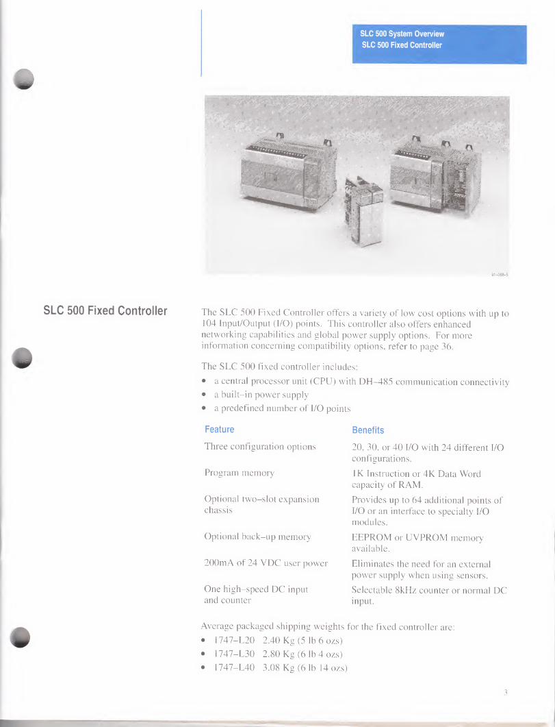
SLC 500 Fixed Controller The SLC 500 Fixed Controller offers a variety of low cost options with up to 104 Input/Output (I/O) points. This controller also offers enhanced networking capabilities and global power supply options. For more information concerning compatibility options, refer to page 36.
The SLC 500 fixed controller includes:
• a central processor unit (CPU) with DH-485 communication connectivity
• a built-in power supply
• a predefined number of I/O points
Feature
Three configuration options
Program memory
Optional two-slot expansion chassis
Optional back-up memory
200mA of 24 VDC user power
One high-speed DC input and counter
Average packaged shipping weights
• 1747-L20 2.40 Kg (5 lb 6 ozs)
• 1747-L30 2.80 Kg (6 lb 4 ozs)
• 1747-L40 3.08 Kg (6 lb 14 ozs)
Benefits
20, 30, or 40 I/O with 24 different I/O configurations.
IK Instruction or 4K Data Word capacity of RAM.
Provides up to 64 additional points of I/O or an interface to specialty I/O modules.
EEPROM or UVPROM memory available.
Eliminates the need for an external power supply when using sensors.
Selectable 8kHz counter or normal DC input.
for the fixed controller are:
3
SLC 500 System Overview
SLC 500 Fixed Controller
Specifications
The following table provides general specifications for the fixed controller.
Description Specification
Program Memory IK Instruction
Standard RAM Capacitor - 2 weeks0
Lithium Battery - 5 years®
Memory Back-up Options EEPROM or UVPROM
Typical Scan Time 8 ms/K
Hold-up Time (Load Dependent) 20 ms to 700 ms
LED Indicators RUN, CPU FAULT, FORCED I/O,
BATTERY LOW
Programming APS or HHT
Power Requirement (max.) 50 VA
Noise Immunity NEMA Standard ICS 2-230
Fuse Protection 120/240 VAC
24VDC
1.25A
1.6A
Environmental conditions
Operating temperature
Storage temperature
Humidity rating
0 to +60° C (+32° to +140° F)
-40° to +85° C (-40° to +185° F)
5 to 95% (non-condensing)
Wire Size #24 AWG to #14 (max.)
Communication DH-485 receive
Certification UL listed, CSA approved
0 1747-L511 only - The capacitor back-up is rated at 35? C (95°F).
® Lithium battery is optional for the L511; standard for the L514.
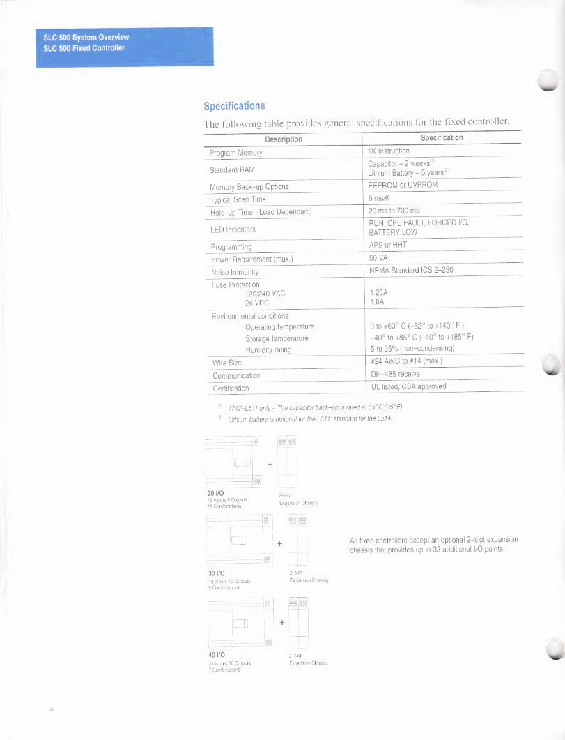
20 I/O 12 Inputs 8 Outputs 11 Combinations
2-slot
Expansion Chassis
1
o 1
30 I/O 18 Inputs 12 Outputs 6 Combinations
2-slot
Expansion Chassis
2
+
11 11
o
40 I/O 2—slot
24 Inputs 16 Outputs Expansion Chassis 7 Combinations
All fixed controllers accept an optional 2-slot expansion
chassis that provides up to 32 additional I/O points.
4
SLC 500 System Overview
SLC 500 Fixed Controller
The following tables provide configuration options for 20, 30, or 40 I/O points. To aid you in configuring your system with additional modules, refer to the Fixed Expansion Chassis Compatibility chart on page 36.
20 I/O Configuration
Catalog Number Input Output Input
Type Output Type
Power
Supply
High-Speed
Counter User Power
1747-L20A 120 VAC
Relay 120/240 VAC No -
1747-L20B Triac 120/240 VAC No -
1747-L20C Relay 120/240 VAC Yes 24V-200mA
1747-L20D Triac 120/240 VAC Yes 24V-200mA
1747-L20E 24 VDC
Sinking Transistor
Source 120/240 VAC Yes 24V-200mA
1747-L20F 12 8 Relay 24 VDC Yes -
1747-L20G Transistor
Source 24 VDC Yes -
1747-L20L 24 VDC
Transistor
Sink 120/240 VAC Yes 24V-200mA
1747-L20N Sourcing Transistor
Sink 24 VDC Yes -
1747-L20P 240 VAC
Triac 120/240 VAC No -
1747-L20R Relay 120/240 VAC No -
30 I/O Configuration
Catalog Number Input Output Input
Type Output Type
Power
Supply High-Speed
Counter User Power
1747-L30A 120 VAC
Relay 120/240 VAC No -
1747-L30B Triac 120/240 VAC No -
1747-L30C 18 12 24 VDC Relay 120/240 VAC Yes 24V-200mA
1747-L30D Sinking Triac 120/240 VAC Yes 24V-200mA
1747-L30L 24 VDC
Sourcing Transistor
Sink 120/240 VAC Yes 24V-200mA
1747-L30P 240 VAC Triac 120/240 VAC No -
40 I/O Configuration
Catalog Number Input Output Input
Type Output Type
Power
Supply High-Speed
Counter User Power
1747-L40A 120 VAC
Relay 120/240 VAC No -
1747-L40B Triac 120/240 VAC No -
1747-L40C Relay 120/240 VAC Yes 24V-200mA
1747-L40E 24 16 24 VDC
Sinking Transistor
Source 120/240 VAC Yes 24V-200mA
1747-L40F Relay 24 VDC Yes -
1747-L40L 24 VDC
Sourcing
Transistor
Sink 120/240 VAC Yes 24V-200mA
1747-L40P 240 VAC Triac 120/240 VAC No -
5
SLC 500 System Overview
SLC 500 Modular Controller
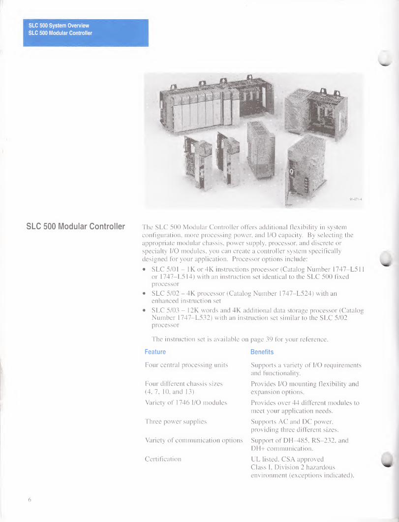
SLC 500 Modular Controller The SLC 500 Modular Controller offers additional flexibility in system configuration, more processing power, and I/O capacity. By selecting the appropriate modular chassis, power supply, processor, and discrete or specialty I/O modules, you can create a controller system specifically designed for your application. Processor options include:
• SLC 5/01 - IK or 4K instructions processor (Catalog Number 1747-L511 or 1747-L514) with an instruction set identical to the SLC 500 fixed processor
• SLC 5/02 - 4K processor (Catalog Number 1747-L524) with an enhanced instruction set
• SLC 5/03 - 12K words and 4K additional data storage processor (Catalog Number 1747-L532) with an instruction set similar to the SLC 5/02 processor
The instruction set is available on page 39 for your reference.
Feature Benefits
Four central processing units
Four different chassis sizes (4, 7, 10, and 13)
Variety of 1746 I/O modules
Three power supplies
Variety of communication options
Certification
Supports a variety of I/O requirements and functionality.
Provides I/O mounting flexibility and expansion options.
Provides over 44 different modules to meet your application needs.
Supports AC and DC power, providing three different sizes.
Support of DH-485, RS-232, and DH+ communication.
UL listed, CSA approved Class I, Division 2 hazardous environment (exceptions indicated).
6
SLC 500 System Overview
SLC 500 Modular Controller
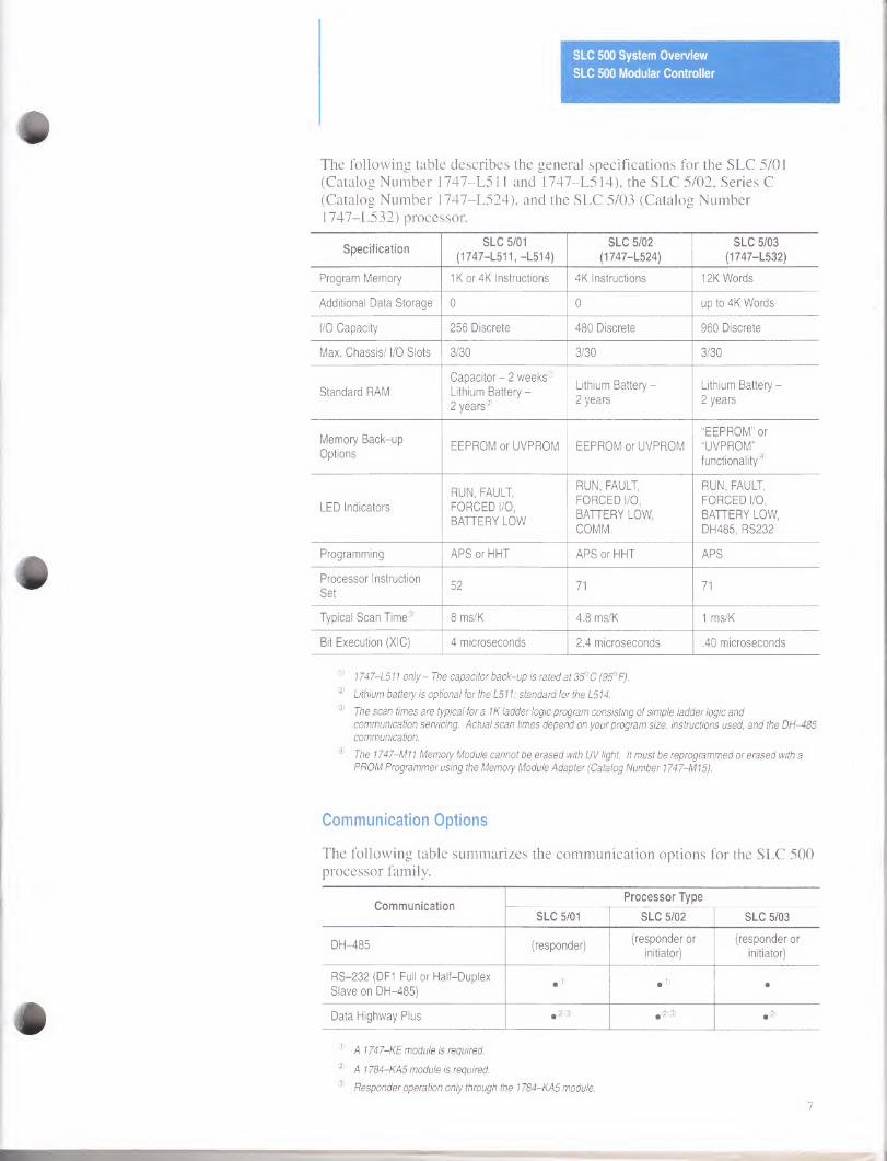
The following table describes the general specifications for the SLC 5/01 (Catalog Number 1747-L511 and 1747-L514), the SLC 5/02, Series C (Catalog Number 1747-L524), and the SLC 5/03 (Catalog Number 1747-L532) processor.
Specification SLC 5/01
(1747-L511, -L514)
SLC 5/02
(1747-L524)
SLC 5/03
(1747-L532)
Program Memory 1Kor4K Instructions 4K Instructions 12K Words
Additional Data Storage 0 0 up to 4K Words
I/O Capacity 256 Discrete 480 Discrete 960 Discrete
Max. Chassis/ I/O Slots 3/30 3/30 3/30
Standard RAM
Capacitor - 2 weeks®
Lithium Battery -
2 years®
Lithium Battery -
2 years
Lithium Battery -
2 years
Memory Back-up
Options EEPROM or UVPROM EEPROM or UVPROM
“EEPROM” or
“UVPROM”
functionality®
LED Indicators
RUN, FAULT,
FORCED I/O,
BATTERY LOW
RUN, FAULT,
FORCED I/O,
BATTERY LOW,
COMM.
RUN, FAULT,
FORCED I/O,
BATTERY LOW,
DH485, RS232
Programming APS or HHT APS or HHT APS
Processor Instruction
Set 52 71 71
Typical Scan Time® 8 ms/K 4.8 ms/K 1 ms/K
Bit Execution (XIC) 4 microseconds 2.4 microseconds .40 microseconds
® 1747-L511 only - The capacitor back-up is rated at 35° C (953 F).
® Lithium battery is optional for the L511; standard for the L514.
® The scan times are typical for a IK ladder logic program consisting of simple ladder logic and communication servicing. Actual scan times depend on your program size, instructions used, and the DH-485 communication.
® The 1747-M11 Memory Module cannot be erased with UV light. It must be reprogrammed or erased with a PROM Programmer using the Memory Module Adapter (Catalog Number 1747-MI5).
Communication Options
The following table summarizes the communication options for the SLC 500 processor family.
Communication Processor Type
SLC 5/01 SLC 5/02 SLC 5/03
DH-485 (responder) (responder or
initiator)
(responder or
initiator)
RS-232 (DF1 Full or Half-Duplex
Slave on DH-485) •© •© •
Data Highway Plus #(M>
® A 1747-KE module is required.
® A 1784-KA5 module is required.
® Responder operation only through the 1784-KA5 module.
1
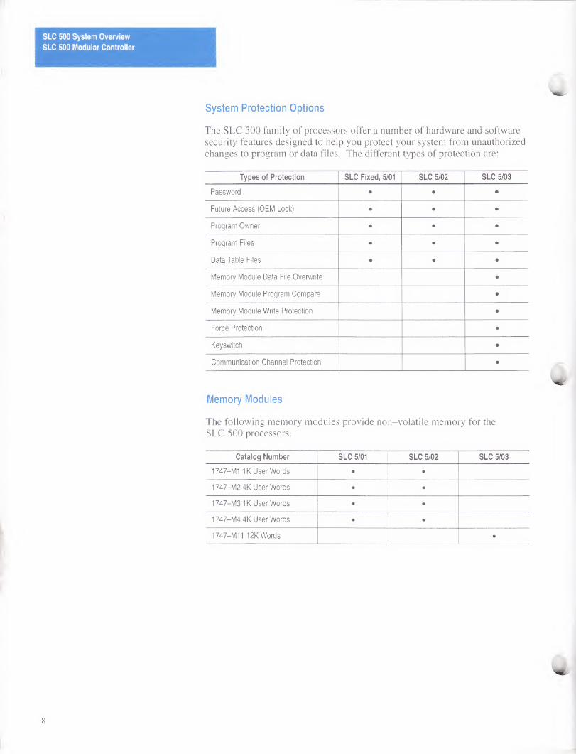
System Protection Options
The SLC 500 family of processors offer a number of hardware and software security features designed to help you protect your system from unauthorized changes to program or data files. The different types of protection are:
Types of Protection SLC Fixed, 5/01 SLC 5/02 SLC 5/03
Password • • •
Future Access (OEM Lock) • • •
Program Owner • • •
Program Files • • •
Data Table Files • • •
Memory Module Data File Overwrite •
Memory Module Program Compare •
Memory Module Write Protection •
Force Protection •
Keyswitch •
Communication Channel Protection •
Memory Modules
The following memory modules provide non-volatile memory for the SLC 500 processors.
Catalog Number SLC 5/01 SLC 5/02 SLC 5/03
1747-MI IK User Words • •
1747-M2 4K User Words • •
1747-M3 IK User Words • •
1747-M4 4K User Words • •
1747-M11 12K Words •
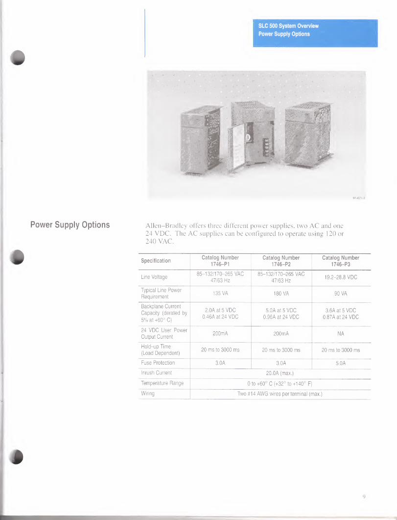
Power Supply Options
#
SLC 500 System Overview
Power Supply Options
Allen-Bradley offers three different power supplies, two AC and one 24 VDC. The AC supplies can be configured to operate using 120 or 240 VAC.
Specification Catalog Number
1746-PI
Catalog Number
1746-P2
Catalog Number
1746-P3
Line Voltage 85-132/170-265 VAC
47/63 Hz
85-132/170-265 VAC
47/63 Hz 19.2-28.8 VDC
Typical Line Power
Requirement 135 VA 180 VA 90 VA
Backplane Current
Capacity (derated by
5% at +60° C)
2.0A at 5 VDC
0.46A at 24 VDC 5.0A at 5 VDC
0.96A at 24 VDC
3.6A at 5 VDC
0.87A at 24 VDC
24 VDC User Power
Output Current 200mA 200mA NA
Hold-up Time
(Load Dependent) 20 ms to 3000 ms 20 ms to 3000 ms 20 ms to 3000 ms
Fuse Protection 3.0A 3.0A 5.0A
Inrush Current 20.0A (max.)
Temperature Range 0 to+60° C (+32° to+140° F)
Wiring Two #14 AWG wires per terminal (max.)
9
SLC 500 System Overview
1746 Discrete I/O Modules
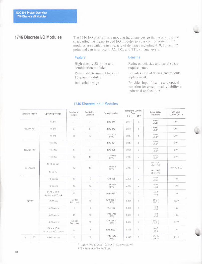
1746 Discrete I/O Modules The 1746 I/O platform is a modular hardware design that uses a cost and space effective means to add I/O modules to your control system. I/O modules are available in a variety of densities including 4, 8, 16, and 32 point and can interface to AC, DC, and TTL voltage levels.
Feature
High density 32-point and combination modules
Removable terminal blocks on 16-point modules
Industrial design
Benefits
Reduces rack size and panel space requirements.
Provides ease of wiring and module replacement.
Provides input filtering and optical isolation for exceptional reliability in industrial applications.
1746 Discrete Input Modules
Voltage Category Operating Voltage Number of
Inputs Points Per Common
Catalog Number Backplane Current
Draw 5 V 24 V
Signal Delay (ms. max)
Off-State Current (max.)
100/120 VAC
85-132 4 4 1746-1A4 0.035 0 on=35
off=45 2mA
85-132 8 8 1746-1A8 0.050 0 on=35
off=45 2mA
85-132 16 16 1746-IA16
(RTB) 0.085 0
on=35
off=45 2mA
200/240 VAC
170-265 4 4 1746-IM4 0.035 0 on=35
off=45 2mA
170-265 8 8 1746-IM8 0.050 0 on=35
off=45 2mA
170-265 16 16 1746-IM16
(RTB) 0.085 0
on=35
off=45 2mA
24 VAC/DC
10-30 DC sink
10-30 AC
16 16 1746-INI 6
(RTB) 0.085 0
on=15 DC
off=15 DC
on=25 AC
off=25 AC
1mA AC & DC
24VDC
10-30 sink 8 8 1746-IB8 0.050 0 on=8
off=8 1mA
10-30 sink 16 16 1746-IB16
(RTB) 0.085 0
on=8
off=8 1mA
18-30 at 50°C
18-26.4 at 60°C sink 32 8 1746-IB32® 0.106 0
on=3
off=3 1mA
10-30 sink 16 (Fast
Response) 16
1746—ITB16 (RTB)
0.085 0 on=0.3
0ff=0.5 1.5mA
10-30 source 8 8 1746—IV8 0.050 0 on=8
off=8 1mA
10-30 source 16 16 1746-IV16
(RTB) 0.085 0
on=8
off=8 1mA
10-30 source 16 (Fast
Response) 16
1746-ITV16 (RTB)
0.085 0 on=0.3
off=0.5 1.5mA
18-30 at 50°C
18-26.4 at 60°C source 32 8 1746-1V32® 0.106 0
on=3
off=3 1mA
5 TTL 4.5-5.5 source 16 16 1746-IG16
(RTB) 0.140 0
on=.25
off=.50 4.1mA
10
® Not certified for Class I, Division 2 hazardous location.
RTB = Removable Terminal Block.
SLC 500 System Overview
1746 Discrete I/O Modules
1746 Discrete Output Modules
Voltage Category
Operating Voltage
Number of Outputs
Points Per Common
Catalog Number
Backplane Current Draw
5 V 24 V
Signal Delay (ms. max)
Off State Leakage (max.)
Load Current at 5 VDC (min.)
Continuous Current per Point (max.)
Continuous Current per
Module (max.)
120/240
VAC 85-265 8 4 1746-0A8 0.185 0
on=0.10
off=11.0 2mA 10mA
1A at 30° C
0.50A at 60° C
8A at 30° C
4A at 60° C
85-265 16 8 1746-OA16
(RTB) 0.370 0
on=0.10
off=11.0 2mA 10mA
0.50A at 30° C
0.25A at 60° C
8A at 30° C
4A at 60° C
24 VDC
10-50
source 8 8 1746-OB8 0.135 0
on=0.10
off=1.0 1mA 1mA
1A at 30° C
0.50A at 60° C
8A at 30° C
4A at 60° C
10-50
source 16 16
1746-OBI 6 (RTB)
0.280 0 on=0.10
off=1.0 1mA 1mA
0.50A at 30° C
0.25A at 60° C
8A at 30° C
4A at 60° C
20.4-26.4 source 16 16 1746OBP160®
(RTB) 0.250 0
on=0.10
off=1.0 1mA 1mA
1.5A at 30° C
1.0A at 60° C
6.4A at
0° to 60° C
5-50
source 32 16 1746-OB32® 0.452 0
on=0.10
off=1.0 1mA 1mA 0.1Aat60° C 3.2A at 60° C
10-50
sink 8 8 1746-0V8 0.135 0
on=0.10
off=1.0 1mA 1mA
1A at 30° C
0.50A at 60° C
8A at 30° C
4A at 60° C
10-50
sink 16 16
1746-OV16 (RTB)
0.270 0 on=0.10
off=1.0 1mA 1mA
0.50A at 30° C
0.25A at 60° C
8A at 30° C
4A at 60° C
5-50
sink 32 16 1746-0V32® 0.452 0
on=0.10
off=1.0 1mA 1mA 0.1Aat60° C 3.2A at 60° C
5 TTL 4.5-5.5 sink 16 16 1746-OG16
(RTB) 0.180 0
on=0.25
off=0.50 0.10mA 0.15mA 0.024A NA
VAC/VDC
Relay
5-265 VAC
5-125 VDC 4 4 1746-0 W40 0.045 0.045
on=10.0
off=10.0 0mA 10mA see relay chart
8.0A
8.0A/common
5-265 VAC
5-125 VDC 8 4 1746-OW81 0.085 0.090
on=10.0
off=10.0 0mA 10mA see relay chart
16.0A
8.0A/common
5-265 VAC
5-125 VDC 16 8
1746-OW16® (RTB)
0.170 0.180 on=10.0
off=10.0 0mA 10mA see relay chart
16.0A
8.0A/common
5-265 VAC
5-125 VDC 8
individually
isolated 1746-0X8®
(RTB) 0.085 0.090
on=10.0
off=10.0 0mA 0mA see relay chart see®
0 Not certified for Class I, Division 2 hazardous location.
® A fused common and blown fuse LED are provided on this module.
® The continuous current per module must be limited to 1440 VA (max.).
Relay Contact Rating Chart
Type Maximum
Volts Ampe sres®
Amperes
Continuous ®
Voltamperes Type Maximum
Volts Amperes
Amperes
Continuous (D
Voltamperes
Make Break Make Break Make Break Make Break
Relay Contact
Ratings for OW4, OW8, and OW16
240 VAC
120 VAC
7.5A
15.0A
0.75A
1.50A 2.5A 1800 VA
Relay Contact
180VA Ratings for
OX8
240 VAC
120 VAC
15.0A
30.0A
1.5A
3.0A 5.0A 3600 VA 360 VA
125VDC 0.22A® 1.0A 28 VA 125VDC 0.22 A® 1.0A 28 VA
24 VDC 1.2A® 2.0A 28 VA 24 VDC 1.2A® 2.0A 28 VA
® Connecting surge suppressors across your external load will extend the life of SLC 500 relay contacts. For recommended surge suppressors when switching AC inductive loads, consult the SLC 500 Installation and Operation User Manual (Catalog Number 1747-NI002). Recommended surge suppression for switching 24 VDC inductive loads is a 1N4004 diode that is reverse wired across the load.
For DC voltage applications, the make/break ampere rating for relay contacts can be determined by dividing 28 VA by the applied DC voltage. For example, 28 VA/48 VDC = 0.58A. For DC voltage applications less than 48V, the make/break ratings for relay contacts cannot exceed 2A. For DC voltage applications greater than 48V, the make/break ratings for relay contacts cannot exceed 1A.
® The continuous current per module must be limited so the module power does not exceed 1440 VA.
11
SLC 500 System Overview
1746 Discrete I/O Modules
1746 Discrete Combination Modules
Voltage Category
Operating Voltage Points Per
Module Points Per Common
Catalog Number Backplane Current Draw
5 V 24 V Specification Reference
lnputs-120
VAC 85-132 VAC
2 inputs
2 outputs 2 1746-104® 0.030 0.025 See specifications for Catalog Numbers 1746-IA4 and 1746-OW4
Continuous Current for 104 is 4.0A
Continuous Current for 108 is 8.0A
Relay Outputs
100/120 VAC
5-265 VAC
5-125 VDC
4 inputs
4 outputs 4 1746-108® 0.060 0.045
6 inputs
6 outputs 6 1746-1012® 0.090 0.07
See specifications for Catalog Numbers 1746-IA16 and OW16
Continuous Current for 1012 is 8.0A
® Not certified for Class I, Division 2 hazardous location.
Specifications
Description Specification
Noise Immunity NEMA Standard ICS 2-230
Vibration (operating)
Displacement - .015 inch
peak to peak at 5 - 57 Hz
Acceleration - 2.5 Gs at 57 - 2000 Hz
Shock (operating) 30 Gs
Isolation 1500 V
Environmental conditions
Operating temperature 0 to+60° C (+32° to+140° F)
Storage temperature -40° to +85° C (-40° to+185° F)
Humidity rating 5 to 95% (non-condensing)
Certification UL listed, CSA approved
Hazardous Environment Classification Class I, Division 2 Hazardous Environment ®
® Some modules are excluded from this certification. Refer to the previous tables for a complete listing.
Bulletin 1492 Interface Modules and Cables
Allen-Bradley’s new wiring system for programmable controllers reduces installation time and increases start-up success. Comprised of a Bulletin 1492 Interface Module and a pre-wired cable, this wiring system can eliminate up to 50 percent of the point-to-point wiring between the programmable controller and field devices. Available for many of the SLC 500 and PLC 16- and 32-point I/O modules, the wiring system provides a lower probability for wiring errors. Optional LEDs on the Interface Module indicate the on/off status of input and output devices, aiding in troubleshooting your wiring system. For more information refer to Publication 1492-1.6.
12
1
SLC 500 System Overview
Specialty I/O Modules
Specialty I/O Modules The SLC 500 family offers specialty I/O modules that enhance your control system. These modules range from analog, motion control, and communication to provide a unique, easy to use interface between the modules and the processor. The following section provides an overview of our specialty I/O modules.
INPUT
(0)IN 0+
(1) IN 0-
(2) ANL COM
(3) IN 1 +
(4) INI-
(5) ANL COM
(6)IN 2+
(7)IN 2-
(8) ANL COM
(9)IN 3+
(10) IN 3-
(ll)ANL COM
OUTPUT INPUT
(0)IN 0+
(I)INO-
(2) ANL COM
(3) IN 1+
(4) INI-
(5) ANL COM
(6) NOT USED
(7)OUT0
(8) ANL COM
(9) NOT USED
(10) OUT 1
(ll)ANL COM
OUTPUT
1746-NI4 1746-NI04I & NI04V 1746—N04I & N04V 1746-NT4
1746 I/O Analog Modules
The SLC 500 family offers six different I/O analog modules for your control applications.
• NI4 input module
• NI04I and NI04V input/output modules
• N04I and N04V output modules
• NT4 Thermocouple module
Feature Benefit
High resolution
Backplane powered
User selectable inputs
Input channel filtering
Image maps directly into the SLC image
16 bit input and 14 bit output converters provide accurate control capabilities.
No external power supply required, reducing system cost.
Configurable per channel for current or voltage inputs.
Rejects high frequency noise that couples into an analog input signal.
Saves memory usage and time.
13
SLC 500 System Overview
Specialty I/O Modules
The following table provides individual module specifications.
Catalog Number
1746- Input Channels
per Module Output Channels
per Module Backplane Current
Draw External 24 VDC Power
Supply Tolerance
NI4 4 differential, voltage or
current selectable per channel NA
25mA at 5 VDC
85mA at 24 VDC NA
NI04I 2 differential, voltage or
current selectable per channel
2 current outputs not
individually isolated
55mA at 5 VDC
145mA at 24 VDC NA
NI04V 2 differential, voltage or
current selectable per channel
2 voltage outputs, not
individually isolated
55mA at 5 VDC
115mA at 24 VDC NA
N04I NA 4 current outputs, not
individually isolated 55mA at 5 VDC
195mA at 24 VDC
24 ±10% at 195mA
(21.6 to 26.4 VDC)
N04V NA 4 voltage outputs, not
individually isolated
55mA at 5 VDC
145mA at 24 VDC
24 ±10% at 145mA
(21.6 to 26.4 VDC)
Important: All analog modules are isolated from each other and from the backplane. If the N04I or the N04V is externally powered, the 24 VDC backplane current draw is OmA.
Specifications
Description Specification
SLC Communication Format 16 Bit Two’s Complement Binary
Field Wiring to Backplane Isolation 500 VDC
Conversion Time 512jlis. for all channels in parallel
Current/Voltage Ranges
NI4 ±10 VDC or ±20mA (current and voltage input)
NI04I ±10 VDC or ±20mA (input) NI04V ±10 VDC (output)
N04I 0 to 21mA (current output) N04V ±10 V (voltage output)
Step Response
Input 60 ms at 95% Output 2.5 ms at 95%
Maximum Wire Size #14 AWG
Terminal Block Removable
Noise Immunity NEMA Standard ICS 2-230
Environmental Conditions
Operating temperature 0 to+60° C (+32° to+140° F)
Storage temperature -40° C to +85° C (-40° to +185° F) Humidity rating 5 to 95% (non-condensing)
Recommended Cable Belden #8761
Certification UL 508 listed, CSA 22.2 142 approved
Hazardous Environment Classification Class I, Division 2 Hazardous Environment
14
SLC 500 System Overview
Specialty I/O Modules
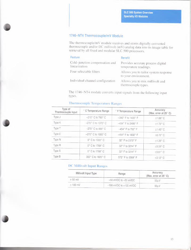
1746-NT4 Thermocouple/mV Module
The thermocouple/mV module receives and stores digitally converted thermocouple and/or DC millivolt (mV) analog data into its image table for retrieval by all fixed and modular SLC 500 processors.
Feature
Cold-junction compensation and linearization
Four selectable filters
Individual channel configuration
Benefit
Provides accurate process digital temperature readings.
Allows you to tailor system response to your environment.
Allows you to mix millivolt and thermocouple types.
The 1746—NT4 module converts input signals from the following input types.
Thermocouple Temperature Ranges
Type of
Thermocouple Input ° C Temperature Range ° F Temperature Range
Accuracy
(Max. error at 25° C)
Type J -210° C to 760° C -346° F to 1400° F ±1.06° C
Type K -270° C to 1370° C -454° F to 2498° F ±1.72° C
TypeT -270° C to 400° C -454° F to 752° F +1.43° C
Type E -270° C to 1000° C -454°F to 1832° F ±0.72° C
Type N 0° C to 1300° C 32° F to 2372° F ±1.39° C
Type R 0° C to 1768° C 32° F to 3214° F ±3.59° C
Type S 0° C to 1768° C 32° F to 3214° F ±3.61° C
Type B 300° C to 1820° C 572° F to 3308° F ±3.12° C
DC Millivolt Input Ranges
Millivolt Input Type Range Accuracy
(Max. error at 25° C)
±50 mV -50 mVDC to +50 mVDC 50|iV
±100 mV -100 mVDC to+100 mVDC 50jliV
15
SLC 500 System Overview
Specialty I/O Modules
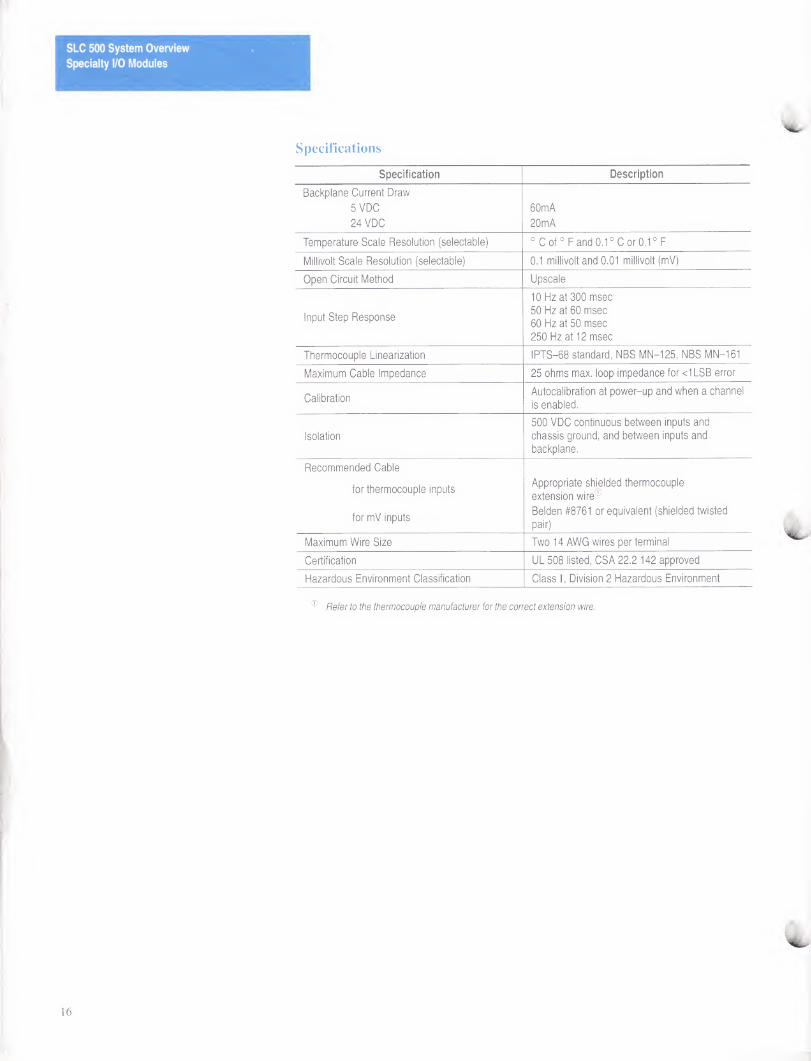
Specifications
Specification Description
Backplane Current Draw
5 VDC
24 VDC
60mA
20mA
Temperature Scale Resolution (selectable) ° C of ° F and 0.1 ° C or 0.1 ° F
Millivolt Scale Resolution (selectable) 0.1 millivolt and 0.01 millivolt (mV)
Open Circuit Method Upscale
Input Step Response
10 Hz at 300 msec
50 Hz at 60 msec
60 Hz at 50 msec
250 Hz at 12 msec
Thermocouple Linearization IPTS-68 standard, NBS MN-125, NBS MN-161
Maximum Cable Impedance 25 ohms max. loop impedance for <1LSB error
Calibration Autocalibration at power-up and when a channel
is enabled.
Isolation
500 VDC continuous between inputs and
chassis ground, and between inputs and
backplane.
Recommended Cable
for thermocouple inputs
for mV inputs
Appropriate shielded thermocouple
extension wire®
Belden #8761 or equivalent (shielded twisted
pair)
Maximum Wire Size Two 14 AWG wires per terminal
Certification UL 508 listed, CSA 22.2 142 approved
Hazardous Environment Classification Class I, Division 2 Hazardous Environment
Refer to the thermocouple manufacturer for the correct extension wire.
SLC 500 System Overview
Specialty I/O Modules
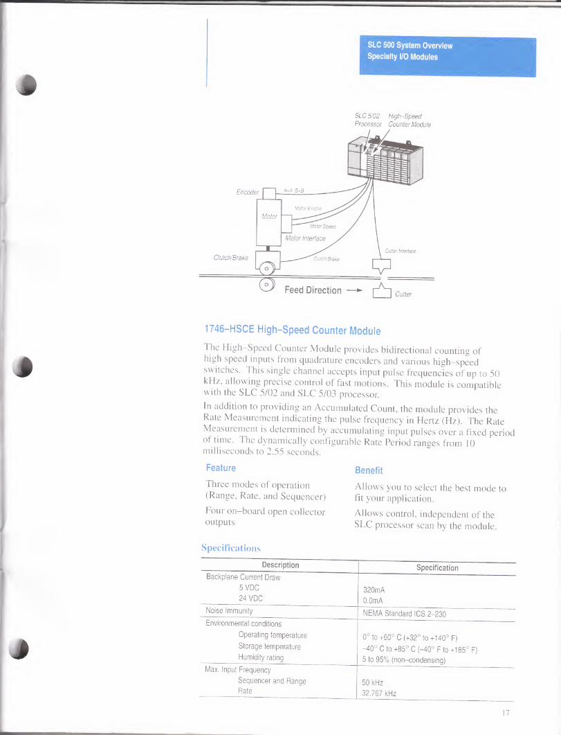
SLC 5/02 High-Speed Processor Counter Module
1746-HSCE High-Speed Counter Module
The High-Speed Counter Module provides bidirectional counting of high speed inputs from quadrature encoders and various high-speed switches. This single channel accepts input pulse frequencies of up to 50 kHz, allowing precise control of fast motions. This module is compatible with the SLC 5/02 and SLC 5/03 processor.
In addition to providing an Accumulated Count, the module provides the Rate Measurement indicating the pulse frequency in Hertz (Hz). The Rate Measurement is determined by accumulating input pulses over a fixed period ol time. The dynamically configurable Rate Period ranges from 10 milliseconds to 2.55 seconds.
Feature
Three modes of operation (Range, Rate, and Sequencer)
Four on-board open collector outputs
Specifications
Description Specification
Backplane Current Draw
5 VDC 320mA 24 VDC 0.0mA
Noise Immunity NEMA Standard ICS 2-230
Environmental conditions
Operating temperature 0° to+60° C (+32° to+140° F) Storage temperature -40° C to +85° C (-40° F to +185° F) Humidity rating 5 to 95% (non-condensing)
Max. Input Frequency
Sequencer and Range 50 kHz Rate 32.767 kHz
Benefit
Allows you to select the best mode to fit your application.
Allows control, independent of the SLC processor scan by the module.
17
SLC 500 System Overview
Specialty I/O Modules
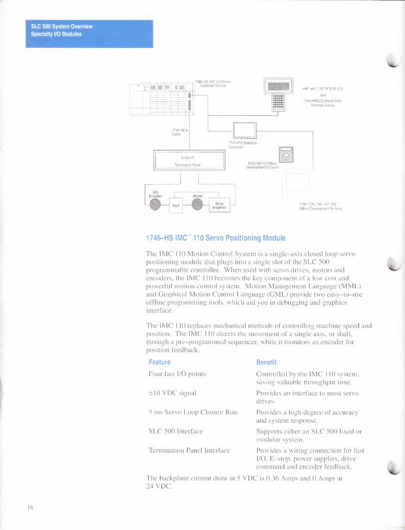
1746-HS IMC™ 110 Servo Positioning Module
The IMC 110 Motion Control System is a single-axis closed loop servo positioning module that plugs into a single slot of the SLC 500 programmable controller. When used with servo drives, motors and encoders, the IMC 110 becomes the key component of a low cost and powerful motion control system. Motion Management Language (MML) and Graphical Motion Control Language (GML) provide two easy-to-use offline programming tools, which aid you in debugging and graphics interface.
The IMC 110 replaces mechanical methods of controlling machine speed and position. The IMC 110 directs the movement of a single axis, or shaft, through a pre-programmed sequencer, while it monitors an encoder for position feedback.
Feature
Four fast I/O points
±10 VDC signal
5 ms Servo Loop Closure Rate
SLC 500 Interface
Termination Panel Interface
The backplane current draw at 5 VDC is 0.36 Amps and 0 Amps at 24 VDC.
Benefit
Controlled by the IMC 110 system, saving valuable throughput time.
Provides an interface to most servo drives.
Provides a high degree of accuracy and system response.
Supports either an SLC 500 fixed or modular system.
Provides a wiring connection for fast I/O, E-stop, power supplies, drive command and encoder feedback.
18
SLC 500 System Overview
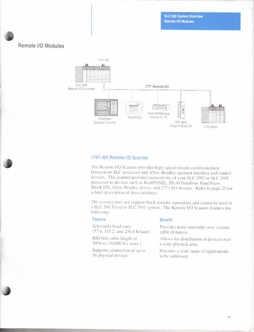
Remote I/O Modules
Remote I/O Modules
1747-SN
11;
Modul
SLC £
ar I/O
i/02
Co
>
ntrc )llei r
PanelView
Operator Terminal
1771 Remote I/O
RediPANEL
Dataliner Message
Display DL 40
1791-8AC
16-point Block I/O 1747-ASB
1747-SN Remote I/O Scanner
The Remote I/O Scanner provides high-speed remote communication between an SLC processor and Allen-Bradley operator interface and control devices. The scanner provides connectivity of your SLC 5/02 or SLC 5/03 processor to devices such as RediPANEL, DL40 Dataliner, PanelView, Block I/O, Allen-Bradley drives, and 1771 I/O devices. Refer to page 23 for a brief description of these products.
The scanner does not support block transfer operations and cannot be used in a SLC 500 Fixed or SLC 5/01 system. The Remote I/O Scanner features the following:
Feature
Selectable baud rates (57.6, 115.2, and 230.4 Kbaud)
RIO link cable length of 3050 m (10,000 ft.) (max.)
Supports connection of up to 16 physical devices
Benefit
Provides noise immunity over various cable distances.
Allows for distribution of devices over a wide physical area.
Provides a wide range of applications to be addressed.
19
SLC 500 System Overview
Remote I/O Modules
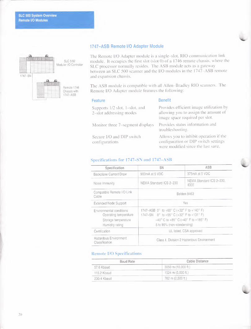
1747-ASB Remote I/O Adapter Module
SLC 5/02
Modular I/O Controller
1747-SN
Remote 1746
Chassis with
1747-ASB
The Remote I/O Adapter module is a single-slot, RIO communication link module. It occupies the first slot (slot 0) of a 1746 remote chassis, where the SLC processor normally resides. The ASB module acts as a gateway between an SLC 500 scanner and the I/O modules in the 1747-ASB remote
and expansion chassis.
The ASB module is compatible with all Allen-Bradley RIO scanners. The Remote I/O Adapter module features the following:
Feature Benefit
Supports 1/2 slot, 1-slot, and Provides efficient image utilization by 2-slot addressing modes allowing you to assign the amount of
image space required per slot.
Monitor three 7-segment displays Provides status information and troubleshooting.
Secure I/O and DIP switch Allows you to inhibit operation if the configurations configuration or DIP switch settings
were modified since the last save.
Specifications for 1747-SN and 1747-ASB
Specification SN ASB
Backplane Current Draw 900mA at 5 VDC 375mA at 5 VDC
Noise Immunity NEMA Standard ICS 2-230 NEMA Standard ICS 2-230,
IEEE
Compatible Remote I/O Link
Cable Belden 9463
Extended Node Support Yes
Environmental conditions
Operating temperature
Storage temperature
Humidity rating
1747-ASB 0° to +60° C (+32° F to +140° F)
1747-SN 0° to +55° C (+32° F to +131 ° F)
-40° C to +85° C (-40° F to +185° F)
5 to 95% (non-condensing)
Certification UL listed, CSA approved
Hazardous Environment
Classification Class I, Division 2 Hazardous Environment
Remote I/O Specifications
Baud Rate Cable Distance
57.6 Kbaud 3050 m (10,000 ft.)
115.2 Kbaud 1524 m (5,000 ft.)
230.4 Kbaud 762 m (2,500 ft.)
20
SLC 500 System Overview
Remote I/O Modules
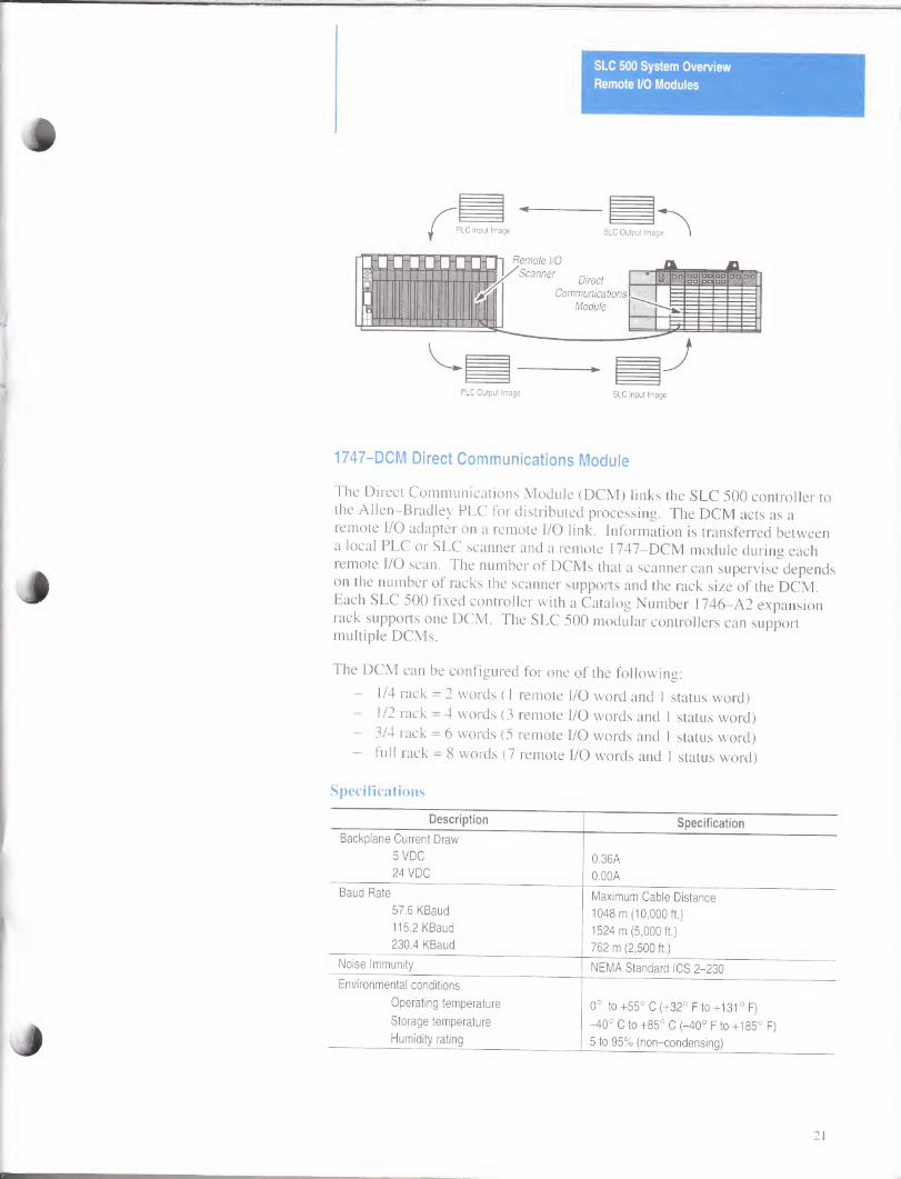
1747-DCM Direct Communications Module
The Direct Communications Module (DCM) links the SLC 500 controller to the Allen-Bradley PLC for distributed processing. The DCM acts as a remote I/O adapter on a remote I/O link. Information is transferred between a local PLC or SLC scanner and a remote 1747—DCM module during each remote I/O scan. The number of DCMs that a scanner can supervise depends on the number of racks the scanner supports and the rack size of the DCM. Each SLC 500 fixed controller with a Catalog Number 1746—A2 expansion rack supports one DCM. The SLC 500 modular controllers can support multiple DCMs.
The DCM can be configured for one of the following:
— 1/4 rack = 2 words (1 remote I/O word and 1 status word)
— 1/2 rack = 4 words (3 remote I/O words and 1 status word)
- 3/4 rack = 6 words (5 remote I/O words and 1 status word)
- full rack = 8 words (7 remote I/O words and 1 status word)
Specifications
Description Specification
Backplane Current Draw
5 VDC 0.36A 24 VDC 0.00A
Baud Rate Maximum Cable Distance 57.6 KBaud 1048 m (10,000 ft.) 115.2 KBaud 1524 m (5,000 ft.) 230.4 KBaud 762 m (2,500 ft.)
Noise Immunity NEMA Standard ICS 2-230
Environmental conditions
Operating temperature 0° to +55° C (+32° F to +131 ° F)
Storage temperature -40° C to +85° C (-40° F to +185° F) Humidity rating 5 to 95% (non-condensing)
21
SLC 500 System Overview
Remote I/O Modules
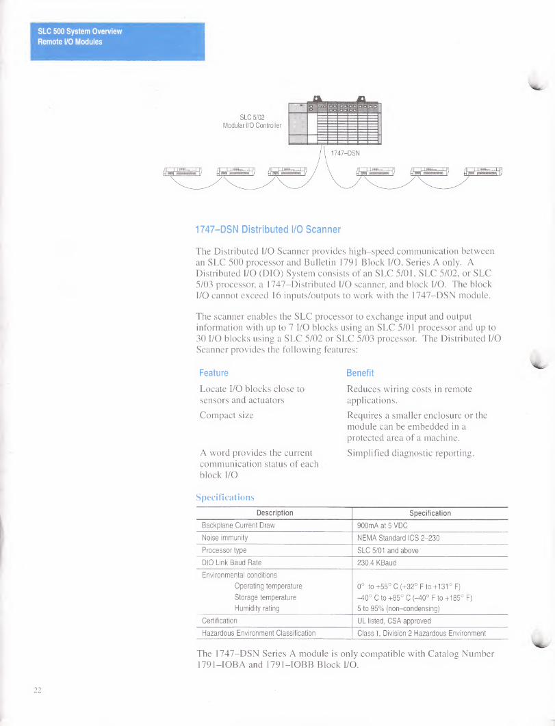
1747-DSN Distributed I/O Scanner
The Distributed I/O Scanner provides high-speed communication between an SLC 500 processor and Bulletin 1791 Block I/O, Series A only. A Distributed I/O (DIO) System consists of an SLC 5/01, SLC 5/02, or SLC 5/03 processor, a 1747-Distributed I/O scanner, and block I/O. The block I/O cannot exceed 16 inputs/outputs to work with the 1747-DSN module.
The scanner enables the SLC processor to exchange input and output information with up to 7 I/O blocks using an SLC 5/01 processor and up to 30 I/O blocks using a SLC 5/02 or SLC 5/03 processor. The Distributed I/O Scanner provides the following features:
Feature
Locate I/O blocks close to sensors and actuators
Compact size
A word provides the current communication status of each block I/O
Benefit
Reduces wiring costs in remote applications.
Requires a smaller enclosure or the module can be embedded in a protected area of a machine.
Simplified diagnostic reporting.
Specifications
Description Specification
Backplane Current Draw 900mA at 5 VDC
Noise immunity NEMA Standard ICS 2-230
Processor type SLC 5/01 and above
DIO Link Baud Rate 230.4 KBaud
Environmental conditions
Operating temperature
Storage temperature
Humidity rating
0° to+55° C (+32° F to+131° F)
-40° C to +85° C (-40° F to +185° F)
5 to 95% (non-condensing)
Certification UL listed, CSA approved
Hazardous Environment Classification Class I, Division 2 Hazardous Environment
22
The 1747-DSN Series A module is only compatible with Catalog Number 1791-IOBA and 1791-IOBB Block I/O.
Remote I/O Devices
\
SLC 500 System Overview
Remote I/O Devices
The following remote I/O devices interface with the SLC 500 remote I/O modules.
1791 Block I/O
Block I/O is a self-contained I/O interface that provides the functionality of the I/O rack, adapter, power supply, and I/O module in a single interface. The block communicates over the Allen-Bradley remote I/O network, joining other Allen-Bradley devices such as operator interface, drives, remote I/O chassis, and vision systems. For additional information refer to Publication 1791-1.3.
2705 RediPANEL Operator Modules
RediPANEL Operator modules combine push buttons, wiring, I/O modules, a message display, and other control panel components in a single pre-packaged, ready-to-install unit. For additional information refer to Publication 2705-1.0.
2706 Dataliner Message Displays
The Dataliner Message Displays provide a cost-effective means of communicating essential machine or process status, alarm conditions, and operator prompts across a machine or a large plant floor. For additional information refer to Publication 2706-1.0.
2711 PanelView Operator Terminals
The PanelView Operator Terminals replace hard-wired control panels with CRT screens that are simple to configure. PanelView terminals provide you with extensive diagnostic information during fault conditions via message windows, alarm windows, and simple graphics. For additional information refer to Publication 2711-1.1.
DRIVES
Adjustable frequency AC drives and high performance DC drives provide exceptional reliability in critical motor control applications. They offer process control, energy savings, and communication to I/O devices such as PanelView terminals through the SLC 500 modular controller. For additional information refer to Publication DHQ-6.
Pyramid Solutions Program (PSP)
The Pyramid Solutions Program provides additional third-party products that interface to remote I/O. For additional information refer to Publication PSP-5.1.
23
SLC 500 System Overview
Remote Communication
Remote Communication SLC 500 products communicate to serial devices using the following interface products.
APS configured for Full-Duplex (DF1)
Dial-up Modem' x Dial-up Modem 1770-KF3
-Cc
m 1 §§ a a
yj
SLC 5/01 Controller SLC 500 Controller with
with 1746-BASIC Module 1747-KE Module SLC 5/02 Controller with
1770-KF3 Module
Only dial-up modems can be used in the above configuration.
1747-KE DH-485/RS-232C Interface Module
The DH-485/RS-232C Interface module provides a bridge between the DH-485 communication network and RS-232 using Allen-Bradley’s DF1 communication protocol. When used in a SLC 500 chassis with a modem, you can:
• remotely program and troubleshoot any single SLC 500 processor
• remotely communicate to a DH-485 network of SLC 500 processors
• remotely collect data directly from the data table of any SLC 500 processor
• use the SLC 500 as a remote terminal unit
1746-BAS BASIC Module and BASIC Development Software
The SLC 500 BASIC module provides two configurable serial channels (RS-232/423, RS-422, and RS-485) and one DH-485 channel, up to 24 Kbytes of battery-backed RAM, plus an additional 32 Kbytes of EEPROM. Using either the 1747-PBASE development software or terminal emulation software, you can use the BASIC module to:
• interface to modems (full- or half-duplex DF1) for transferring data from any SLC 500 processor to other DF1 devices at remote locations
• provide RTU functionality including dial-up and report by exception
• generate and print reports
• perform floating point math functions
• remotely communicate via other protocols using the ProSoft chips
24
SLC 500 System Overview
Remote Communication
1770-KF3 DH-485 Communication Interface Module
The DH-485 Communication Interface module is a standalone device that provides the same functionality as the 1747-KE interface module. However, when communicating from a remote location to a DH-485 network, the 1770-KF3 does not require a 1747-AIC module.
Remote I/O Functions
The above communication modules connect to most types of dial-up network or direct connect modems. The following modems can be used:
• Manual — typically acoustically coupled modems
• DTE Controlled Answer - attached to phone lines
• Auto Answer - automatically answers and hangs-up the phone
• Direct Connect - connected to a dedicated, leased phone line
The following table shows how serial devices interface with SLC 500 products.
Feature 1770-KF3 1747-KE 1746-BAS
APS functions supported • • •
Module specific programming language • •
External power required •
Standalone “desktop” •
SLC 500 I/O module • •
Terminal required for configuration •
Descriptive configuration menus •
Dial-up modem support •
Link coupler required for point-to-point communication
•
Link coupler required for network communication •
DH-485 support • • •
DH-485 token passing master • • •
Full-Duplex DF1 support • • •
Half-duplex DF1 slave - local mode • • •
Half-duplex DF1 slave - remote mode • • •
Responds to polls from DF1 half-duplex master • • •
Report by exception capability • • •
ProSoft Protocol Chip support •
25
SLC 500 System Overview
Networking Options
Networking Options SLC 500 programmable controllers communicate across an embedded DH-485 network for program support and monitoring. The following products provide networking options for the SLC 500 programmable controllers.
IBM-PC or compatible with
1784—KR, DH-485 PC Interface
DH-485 [g 1747—AIC
Isolated Link Coupler
SLC 500
Fixed I/O Controller
1784-KR Personal Computer Interface Card
The Personal Computer Interface Card provides an interface for IBM XT/AT and compatible computers to communicate over the Allen-Bradley DH-485 communication network. This includes communication to the Allen-Bradley line of SLC 500 programmable controllers.
Feature Benefit
PC XT/AT Interface to DH-485
DH-485 isolation
Reduced personal computer overhead
Eliminates the need for the personal interface converter when using APS.
Eliminates the need for an isolated link coupler.
Provides a faster update time for the user interface through the co-processor.
Specifications
Description Specification
Power Requirements 5 VDC, 1.8A
Outputs RS-485 electrical/DH—485 protocol
Hardware Interrupt IRQ2, IRQ3, IRQ4, IRQ5
Cable Length (max.) 1219m (4000 ft.)
Environmental conditions
Operating temperature
Storage temperature
Humidity rating
0 to+60° C (+32° to+140° F)
-40° to +85° C (-40° to +185° F)
5 to 95% (non-condensing)
26
SLC 500 System Overview
Networking Options
6001-F2E Standard Driver
The Standard Driver allows the 1784-KR card to be used on the DH-485 communication network for data acquisition applications. This allows you to write ‘C’ application programs that communicate directly over the DH-485 network to stations such as the SLC 500. Non-token passing slave stations such as the 2755-DM6 Bar Code Reader are also supported.
Feature Benefit
Establishes communications with devices on the DH-485 network.
Eliminates the learning curve of new software packages.
Aids in data table read or write diagnostic commands.
Provides a Set of Linkable ‘C’ Function Calls
Supports Microsoft® ‘C’ v5.1 and Borland Turbo ‘C’ v2.0 Compilers
Provides application libraries
1747—AIC Isolated Link Coupler for DH-485 Connection
The Isolated Link Coupler provides an electrically isolated network connection for an SLC 500 controller. One coupler is required at each DH^185 network drop. The coupler includes a 304.8 mm (12 in.) cable for connection to the programmable controller. Note that a maximum of 32 devices can be connected to the network.
27
SLC 500 System Overview
Programming Options
Programming Options
91-068-7
The following section describes two types of programming options available for the SLC 500. The first is the 1747-PA2E Advanced Programming Software (APS) and the second is the 1747-PT1 Hand-Held Terminal (HHT) that also includes the 1747-PTA1E memory pak.
1747-PA2E Advanced Programming Software
The Advanced Programming Software (APS) v4.01 and later, enables you to program the SLC 500 family processors using the Allen-Bradley T50 Industrial Terminal, T45 and T47 Portable Terminals, or IBM-AT/XT, or compatible personal computer. Included in the APS software is the APS Import/Export Utility (APSIE). This software utility allows you to convert APS archive files and program documentation into ASCII text files and vice versa.
Feature Benefit
Full-line processor support
DH-485 and DF1 support
Runtime online editing
Command line entry of instructions and parameters
Online context sensitive help
Programs any SLC 500 Fixed processor, SLC 5/01. SLC 5/02, and SLC 5/03 modular processors.
Provides a variety of communication options to meet your application requirements.
Allows entry of programs and data while online in the Run mode when using a SLC 5/03 processor.
Provides time saving keystrokes.
Provides quick access to instructions and status file information.
28
SLC 500 System Overview
Programming Options
Feature Benefit
System auto configuration Automatically reads system configuration information (including I/O and chassis data), saving you valuable startup time.
Cut, copy, paste editor
Search and replace
Permits ladder logic to be re-used.
Allows quick modification of ladder logic to match unforeseen hardware changes.
System Specifications
Description Specification
Computer 3.0 Mbyte of hard disk space
Hardware 640Kbyte RAM, minimum 550Kbyte free at execution. Extended or expanded memory recommended, but not required.
Operating System DOS 3.1 and higher
Printer Interface parallel or serial
80,132, or 255 columns
Refer to page 39 for the instruction set.
1747-PIC Interface Converter
The 1747-PIC Interface Converter changes RS-232 signal levels from your personal computer to RS-485 signal levels for the SLC 500 controller. The DH-485 protocol driver is provided by either the 1747-PA2E or 1747-PBASE software.
The converter includes an 279.4 mm (11 in) 25 pin ribbon cable for connection to the computer and a cable (Catalog Number 1746-C10) for connection to the SLC 500 controller.
29
SLC 500 System Overview
Programming Options
1747-PT1 Hand-Held Terminal and 1747-PTA1E Programming Memory Pak
The Hand-Held Terminal (HHT) v2.03 is a powerful portable programming platform used to configure the SLC 500 Fixed, SLC 5/01, and the SLC 5/02 processors, enter or modify an application program, monitor the execution of the application program in real-time, or troubleshoot an application program. The HHT accepts programs with a maximum data table size of 6K. Each rung may contain up to 127 instructions. This differs from APS which has a maximum data table size of 16K and each rung can contain 128 instructions.
The programming memory pak is interchangeable and available in four languages. When used with the memory pak (v2.03), the HHT can be used to program the SLC 5/02 processor as well as connect to the DH-485 network. Note that the HHT does not support nested branching or conditional output branches.
Feature
Rugged construction
Menu-driven firmware
LCD display
Network diagnostics
ZOOM function
Formatted display
Benefit
Designed for a variety of industrial environments.
Displays step-by-step directions.
Shows up to five rungs of ladder logic at one time.
Checks the operation of the DH-485 network (v2.03).
Displays detailed instruction information.
Displays PID and MSG instructions (v2.03).
Specifications
Description Specification
Display 8 line x 40 character super-twist nematic LCD
Keyboard 30 keys
Operating Power 0.105A (max.) at 24 VDC
Communication DH-485
Environmental conditions
Operating temperature
Storage temperature
Humidity rating
Oto +40° C (+32° to +104° F)
-20° to +65° C (-4° to +149° F)
5 to 95% (non-condensing)
Certification UL listed, CSA approved
Refer to page 39 for the instruction set.
30
SLC 500 System Overview
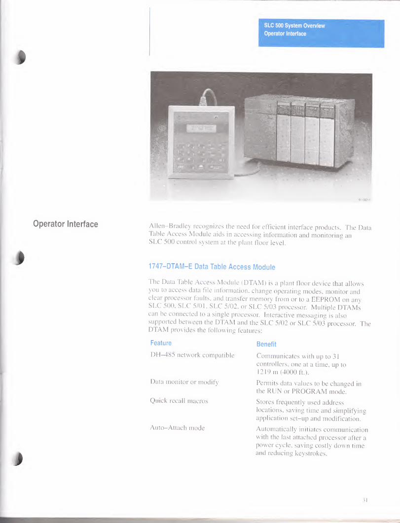
Operator Interface
91-062-1
Operator Interface
J
Allen-Bradley recognizes the need for efficient interface products. The Data Table Access Module aids in accessing information and monitoring an SLC 500 control system at the plant floor level.
1747-DTAM-E Data Table Access Module
The Data Table Access Module (DTAM) is a plant floor device that allows you to access data file information, change operating modes, monitor and clear processor faults, and transfer memory from or to a EEPROM on any SLC 500. SLC 5/01, SLC 5/02, or SLC 5/03 processor. Multiple DTAMs can be connected to a single processor. Interactive messaging is also supported between the DTAM and the SLC 5/02 or SLC 5/03 processor. The DTAM provides the following features:
Feature Benefit
DFM185 network compatible
Data monitor or modify
Quick recall macros
Auto-Attach mode
Communicates with up to 31 controllers, one at a time, up to 1219 m (4000 ft.).
Permits data values to be changed in the RUN or PROGRAM mode.
Stores frequently used address locations, saving time and simplifying application set-up and modification.
Automatically initiates communication with the last attached processor after a power cycle, saving costly down time and reducing keystrokes.
31
SLC 500 System Overview
Operator Interface
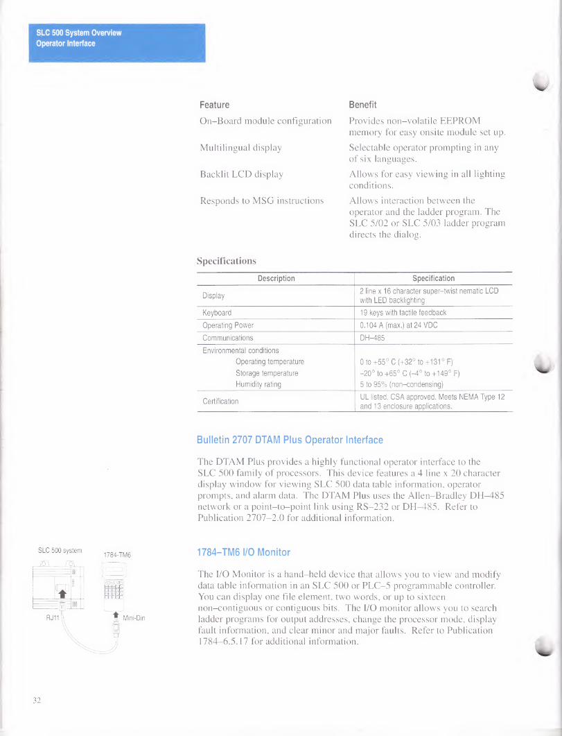
SLC 500 system
i&\ ra
RJ11
Feature
On-Board module configuration
Multilingual display
Backlit LCD display
Responds to MSG instructions
Benefit
Provides non-volatile EEPROM memory for easy onsite module set up.
Selectable operator prompting in any of six languages.
Allows for easy viewing in all lighting conditions.
Allows interaction between the operator and the ladder program. The SLC 5/02 or SLC 5/03 ladder program directs the dialog.
Specifications
Description Specification
Display 2 line x 16 character super-twist nematic LCD
with LED backlighting
Keyboard 19 keys with tactile feedback
Operating Power 0.104 A (max.) at 24 VDC
Communications DH-485
Environmental conditions
Operating temperature
Storage temperature
Humidity rating
0 to +55° C (+32° to +131 ° F)
-20° to +65° C (-4° to +149° F)
5 to 95% (non-condensing)
Certification UL listed, CSA approved. Meets NEMA Type 12
and 13 enclosure applications.
Bulletin 2707 DTAM Plus Operator Interface
The DTAM Plus provides a highly functional operator interface to the SLC 500 family of processors. This device features a 4 line x 20 character display window for viewing SLC 500 data table information, operator prompts, and alarm data. The DTAM Plus uses the Allen-Bradley DH-485 network or a point-to-point link using RS-232 or DH-485. Refer to Publication 2707-2.0 for additional information.
1784-TM6
\_/
OAVB
1784-TM6 I/O Monitor
The I/O Monitor is a hand-held device that allows you to view and modify data table information in an SLC 500 or PLC-5 programmable controller. You can display one file element, two words, or up to sixteen non-contiguous or contiguous bits. The I/O monitor allows you to search ladder programs for output addresses, change the processor mode, display fault information, and clear minor and major faults. Refer to Publication 1784-6.5.17 for additional information.
32
Allen—Bradley Support
Configuring an SLC 500 System
SLC 500 System Overview
Support
In today’s competitive environment, when you buy any product, you expect that product to meet your needs. You also expect the manufacturer of that product to back it up with the kind of customer service and product support that will prove you made a wise purchase.
As the people who design, engineer, and manufacture your Industrial Automation Control equipment, Allen-Bradley has a vested interest in your complete satisfaction with our products and services.
Allen-Bradley offers support services worldwide, with over 75 Sales/Support Offices, 512 authorized Distributors and 260 authorized Systems Integrators located throughout the United States alone, plus Allen-Bradley representatives in every major country in the world.
Contact your local Allen-Bradley representative for:
• sales and order support
• product technical training
• warranty support
• support service agreements
The following section describes:
• How to configure an SLC 500 chassis style system
• How to determine 1746 I/O module compatibility
• Available instructions used with the 1747-PA2E Advanced Programming Software and the 1747-PT1 Hand-Held Terminal
• Fixed controller wiring diagrams
• Dimensions for SLC 500 fixed and modular controllers, and compatible products
33
SLC 500 System Overview
Configuring an SLC 500 System
SLC 500 Rack Configuration This worksheet is intended to help you configure a modular style system. If Instructions a fixed I/O controller is more appropriate for your application, refer to page 3
of this System Overview. Each worksheet is designed to help you configure one chassis of I/O. If multiple chassis are necessary for your application, additional chassis should be configured using another worksheet.
1. Estimate the total amount of memory this system requires
a. Add up the number of discrete I/O points and place it in (a).
b. Add up the number of analog I/O points and place it in (b).
c. Add up the number of specialty I/O modules and place it in (c).
d. Multiply a, b, and c by the number indicated.
e. Total those numbers to give you a memory estimate.
2. Select a processor
Required Memory Required I/O Catalog Number
0 to IK Less than 256 1747-L511
IK to 4K Less than 256 1747-L514
IK to 4K Greater than 256 1747-L524
Greater than 4K Greater than 256 1747-L532
Place your choice into slot 0 of chassis 1 on the worksheet.
3. Select the I/O
a. If multiple chassis system, make copies for each chassis.
b. Write in the chassis number.
c. Write in the appropriate slot numbers.
d. Refer to pages 10 through 12 for discrete I/O selection.
e. Refer to pages 13 through 18 for specialty and analog I/O selection.
f. Using the worksheet, list each I/O module in the slot you desire.
g. List the power consumption of each module in the designated columns. Be sure to account for future expansion.
h. When the chassis is complete, add up each power consumption column.
4. Select the correct Power Supply
a. Compare the Power Consumption totals with each power supply.
b. Choose the smallest power supply that provides sufficient power. Note that the current shown is rated at 55° C.
5. Select the Chassis
a. Add up the number of slots used.
b. Select the smallest chassis which can hold your I/O. Be sure to account for future expansion.
6. Select the Miscellaneous Devices
To complete your system, include devices such as: Cables
Communication Interfaces Operator Interface Devices Memory Modules
34
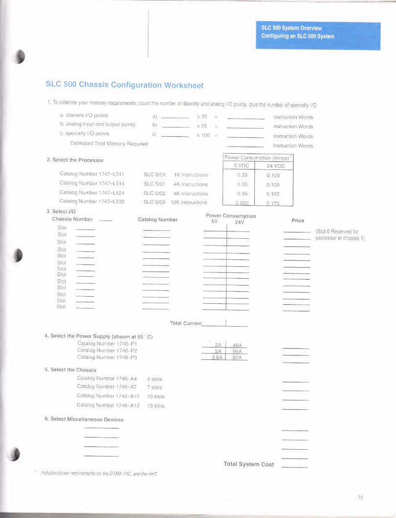
SLC 500 Chassis Configuration Worksheet
1. To estimate your memory requirements, count the number of discrete and analog I/O points, plus the number of specialty I/O.
a. discrete I/O points a) x i n - Instruction Words b. analog input and output points b) x PFi - Instruction Words c. specialty I/O points C) x 100 - Instruction Wnrrta
Estimated Total Memory Required Instruction Words
2. Select the Processor Power Consumption (Amps)®
5 VDC 24 VDC
Catalog Number 1747-L511 SLC 5/01 IK Instructions 0.35 0.105
Catalog Number 1747-L514 SLC 5/01 4K Instructions 0.35 0.105
Catalog Number 1747-L524 SLC 5/02 4K Instructions 0.35 0.105 Catalog Number 1747-L532 SLC 5/03 12K Instructions 0.500 0.175
3. Select I/O
Chassis Number
Slot _ Slot _
Slot _
Slot _ Slot _ Slot _ Slot _ Slot _ Slot _ Slot _ Slot _ Slot _ Slot _
Catalog Number Power Consumption
5V 24V Price
(Slot 0 Reserved for
processor in chassis 1)
Total Current.
4. Select the Power Supply (shown at 55° C)
Catalog Number 1746-PI 2A .46A Catalog Number 1746-P2 5A .96A Catalog Number 1746-P3 3.6A .87A
5. Select the Chassis
Catalog Number 1746-A4 4 slots
Catalog Number 1746-A7 7 slots
Catalog Number 1746-A10 10 slots
Catalog Number 1746-A13 13 slots
6. Select Miscellaneous Devices
0 Includes power requirements for the DTAM, PIC, and the HHT.
Total System Cost
35
SLC 500 System Overview
Configuring an SLC 500 System
Fixed I/O Chassis Module Compatibility
The table on the following page represents combinations of modules and indicates whether or not each combination is valid. The chart on page NO TAG represents the region of operating current that the fixed I/O expansion chassis supports.
Important: When referencing either method on the following pages, be aware that there are certain conditions that affect the compatibility characteristics of the BASIC module (BAS) and the DH-485/RS-232C module (KE).
When you use the BAS module or the KE module to supply power to a 1747-AIC Link Coupler, the Link Coupler draws its power through the module. The higher current drawn by the AIC at 24 VDC is calculated and recorded in the tables for the modules identified as BASn (BAS networked) or KEn (KE networked). Make sure to refer to these modules if your application uses the BAS or KE module in this way.
Tabular Method ^0
Using the table on the next page, locate both of the modules you plan to use in the fixed I/O expansion chassis. Follow the top row across until you find one of the modules. Then follow the right column down until you find the other module. The symbol shown in the table cell that marks their intersection gives you information you must know before installing the modules.
R A dot indicates a valid combination.
| | No symbol indicates an invalid combination.
|~v~| A triangle indicates an external 24 VDC power supply may be required. (Refer to the Analog I/O Module User Manual, 1746-NM003.)
You can use either of two methods to determine whether the 2-slot, fixed I/O expansion chassis will support a specific combination of modules.
• tabular method
• charting method
36
SLC 500 System Overview
Configuring an SLC 500 System
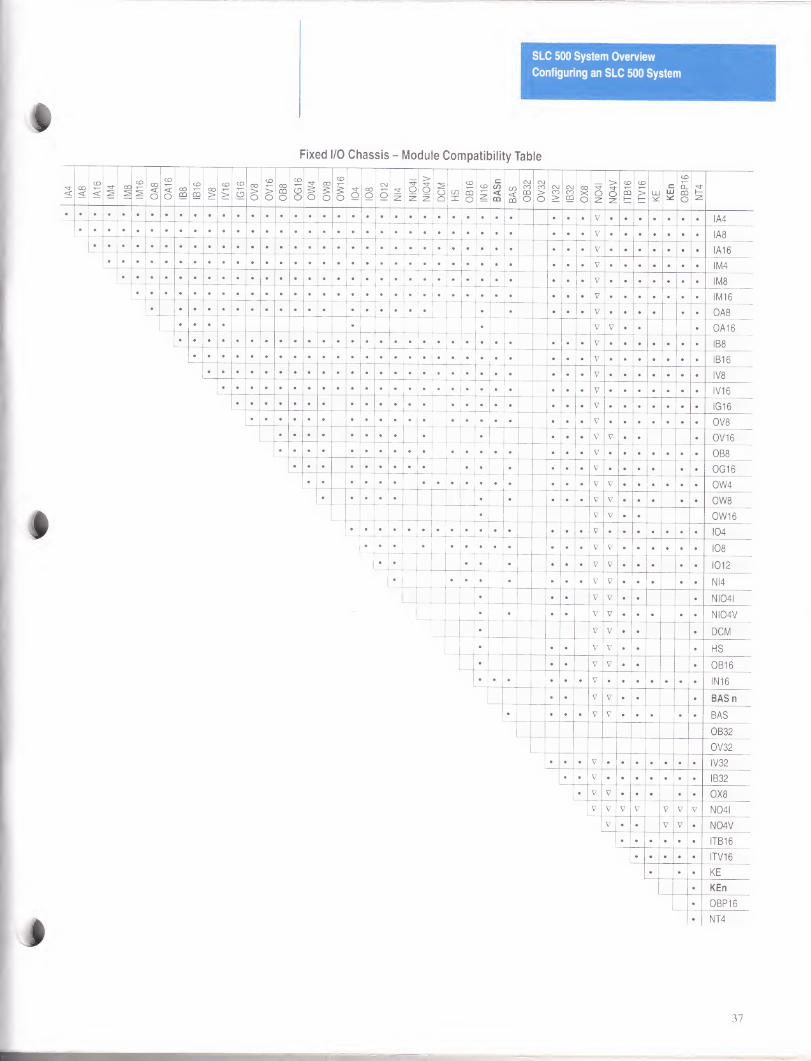
Fixed I/O Chassis - Module Compatibility Table
37
SLC 500 System Overview
Configuring an SLC 500 System
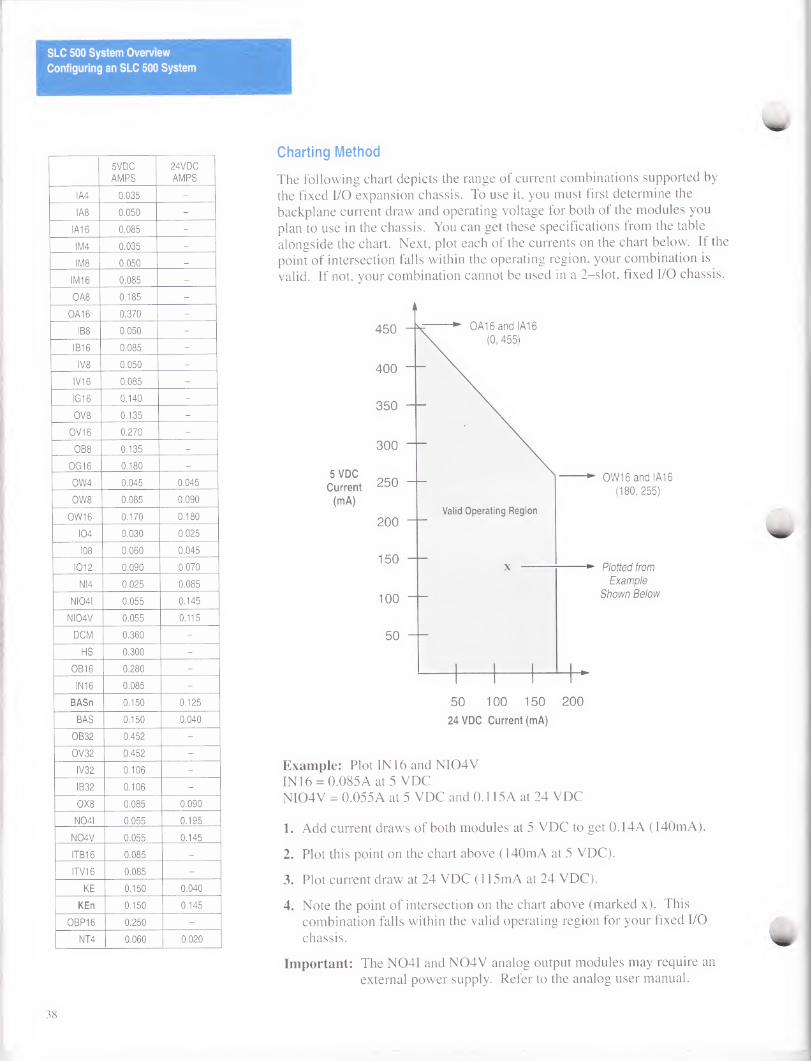
5VDC
AMPS
24VDC
AMPS
IA4 0.035 -
IA8 0.050 -
IA16 0.085 -
IM4 0.035 -
IM8 0.050 _
IM16 0.085 -
OA8 0.185 -
OA16 0.370 -
IB8 0.050 -
IB16 0.085 -
IV8 0.050 -
IV16 0.085 -
IG16 0.140 -
OV8 0.135 -
0V16 0.270 -
OB8 0.135 -
OG16 0.180 _
OW4 0.045 0.045
OW8 0.085 0.090
OW16 0.170 0.180
104 0.030 0.025
108 0.060 0.045
1012 0.090 0.070
NI4 0.025 0.085
NI04I 0.055 0.145
NI04V 0.055 0.115
DCM 0.360 -
HS 0.300 -
0B16 0.280 -
INI 6 0.085 -
BASn 0.150 0.125
BAS 0.150 0.040
OB32 0.452 -
OV32 0.452 -
IV32 0.106 -
IB32 0.106 -
0X8 0.085 0.090
N04I 0.055 0.195
N04V 0.055 0.145
ITB16 0.085 _
ITV16 0.085 -
KE 0.150 0.040
KEn 0.150 0.145
0BP16 0.250 -
NT4 0.060 0.020
Charting Method
The following chart depicts the range of current combinations supported by the fixed I/O expansion chassis. To use it, you must first determine the backplane current draw and operating voltage for both of the modules you plan to use in the chassis. You can get these specifications from the table alongside the chart. Next, plot each of the currents on the chart below. If the point of intersection falls within the operating region, your combination is valid. If not, your combination cannot be used in a 2-slot, fixed I/O chassis.
OW16 and IA16
(180,255)
Plotted from
Example
Shown Below
Example: Plot IN 16 and NI04V INI6 = 0.085A at 5 VDC NI04V = 0.055A at 5 VDC and 0.115A at 24 VDC
1. Add current draws of both modules at 5 VDC to get 0.14A (140mA).
2. Plot this point on the chart above (140mA at 5 VDC).
3. Plot current draw at 24 VDC (115mA at 24 VDC).
4. Note the point of intersection on the chart above (marked x). This combination falls within the valid operating region for your fixed I/O
chassis.
Important: The N04I and N04V analog output modules may require an external power supply. Refer to the analog user manual.
38
SLC 500 System Overview
Configuring an SLC 500 System
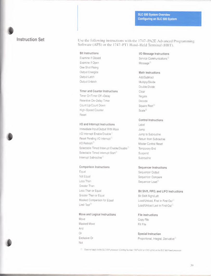
Instruction S©t Use the following instructions with the 1747—PA2E Advanced Programming Software (APS) or the 1747-PT1 Hand-Held Terminal (HHT).
Bit Instructions I/O Message Instructions
Examine If Closed Service Communications®
Examine If Open Message®
One Shot Rising
Output Energize Math Instructions
Output Latch Add/Subtract
Output Unlatch Multiply/Divide
Double Divide
Timer and Counter Instructions Clear
Timer OnTimer Off -Delay Negate
Retentive On-Delay Timer Decode
Count Up/Count Down Square Root®
High-Speed Counter Scale®
Reset
Control Instructions
I/O and Interrupt Instructions Label
Immediate Input/Output With Mask Jump
I/O Interrupt Enable/Disable0 Jump to Subroutine
Reset Pending I/O Interrupt® Return from Subroutine
I/O Refresh® Master Control Reset
Selectable Timed Interrupt Enable/Disable® Temporary End
Selectable Timed Interrupt Start® Suspend
Interrupt Subroutine® Subroutine
Comparison Instructions Sequencer Instructions
Equal Sequencer Output
Not Equal Sequencer Compare
Less Than Sequencer Load®
Greater Than
Less Than or Equal Bit Shift, FIFO, and LIFO Instructions
Greater Than or Equal Bit Shift Right/Left
Masked Comparison for Equal Load/Unload, First In First Out®
Limit Test® Load/Unload Last In First Out®
Move and Logical Instructions File Instructions
Move Copy File
Masked Move Fill File
And
Or Special Instruction
Exclusive Or Proportional, Integral, Derivative®
Not
® Does not apply to the SLC 5/01 processor (Catalog Number 1747-L511 or 1747-L514) or the SLC 500 Fixed processor.
39
*
SLC 500 System Overview
Configuring an SLC 500 System
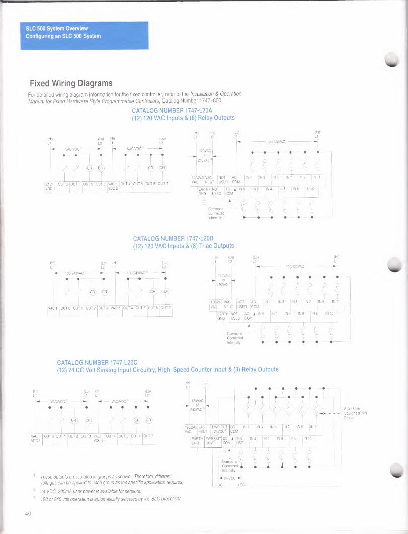
Fixed Wiring Diagrams For detailed wiring diagram information for the fixed controller, refer to the Installation & Operation Manual for Fixed Hardware Style Programmable Controllers, Catalog Number 1747-800.
CATALOG NUMBER 1747-L20A (12) 120 VAC Inputs & (8) Relay Outputs
(Hi) (Lo) (Hi) (Lo)
LI L2 LI L2
(Hi) (Lo) (Lo) (Hi)
CATALOG NUMBER 1747-L20B
(12) 120 VAC Inputs & (8) Triac Outputs
(Hi)
LI
(Lo) (Hi)
L2 LI
(Hi) (Lo) (Lo)
(Lo)
L2
1 L2 ! L2
120VAC
or
240VAC®
(Hi)
LI
■ 100/120VAC
120/240 VAC NOT AC INI IN 3 IN 5 IN 7 IN 9 IN 11
VAC NEUT USED COM
EARTH NOT AC A IN0 IN 2 IN 4 IN 6 IN 8 IN 10
GND USED COM 1
6 ,i .6 ,6 Commons -
Connected
Internally
CATALOG NUMBER 1747-L20C (12) 24 DC Volt Sinking Input Circuitry, High-Speed Counter Input & (8) Relay Outputs
(Hi)
LI
(Lo) (Hi)
L2 LI
- VAC/VDC®
rr S S (£
- VAC/VDC® 120VAC
or «
240VAC®
VAC/ OUTO OUT 1 OUT 2 OUT 3 VAC/ OUT 4 OUT 5 OUT 6 OUT 7
VDC 1 VDC 2
120/240 VAC PWR OUT DC INI IN 3 IN 5 IN 7 IN 9 IN 11
VAC NEUT +24VDC® COM
EARTH PWR OUT DC A IN0 IN 2 IN 4 IN 6 IN 8 IN 10
GND COM® COM 1 HSC
® These outputs are isolated in groups as shown. Therefore, different voltages can be applied to each group as the specific application requires.
® 24 VDC, 200mA user power is available for sensors.
® 120 or 240 volt operation is automatically selected by the SLC processor.
. i \S * i \ i \ i imons 099099 nected ,>-*-•-1-•-i-
Commons
Connected
Internally
24 VDC -
-DC+ DC
40
SLC 500 System Overview
Configuring an SLC 500 System
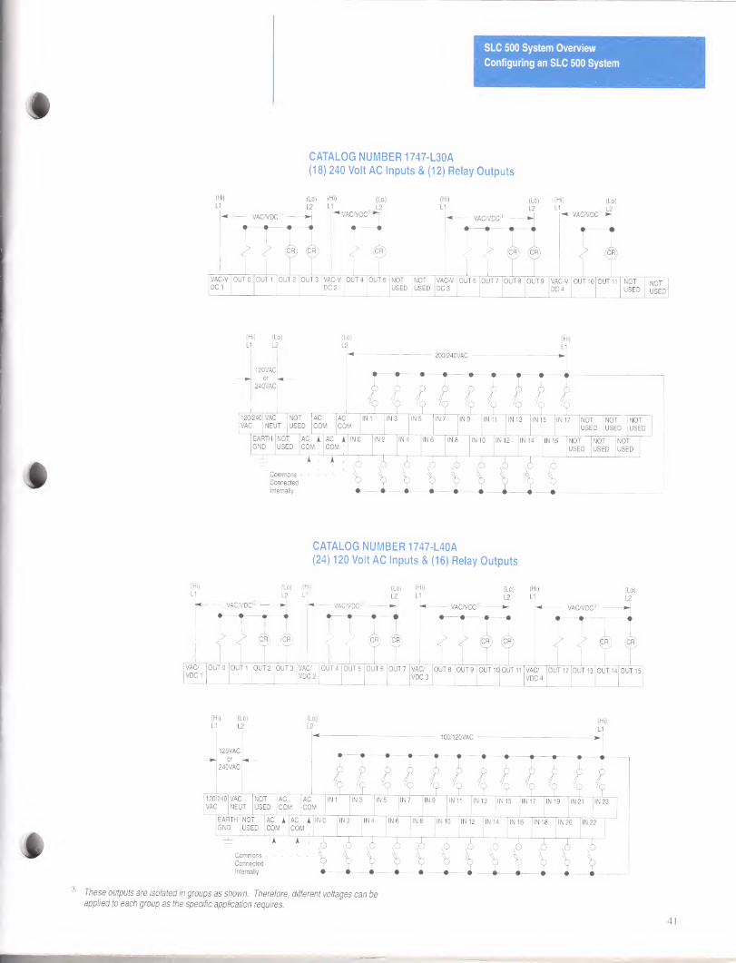
CATALOG NUMBER 1747-L30A
(18) 240 Volt AC Inputs & (12) Relay Outputs
(Hi)
LI (Lo) L2
(Lo)
L2
120VAC
or
240VAC
(Hi)
LI
- 200/240VAC
?,, V?,7? 7? 7? 7? 7? 120/240
VAC
VAC
NEUT
NOT
USED
AC
COM
AC
COM
IN 3 IN 9 IN 13 IN 15 IN 17 NOT
USED
NOT
USED
NOT
USED
EARTH NOT AC A AC A IN0 IN 2 IN 4 IN 6 IN 8 IN 10 IN 12 IN 14 IN 16 NOT NOT NOT GND USED COM 1
i
COM 1
i USED USED USED
Commons -
Connected
Internally
CATALOG NUMBER 1747-L40A
(24) 120 Volt AC Inputs & (16) Relay Outputs
(Hi)
LI
(Lo)
L2
(Lo)
L2
120VAC
or
240VAC
(Hi)
LI
— 100/120VAC -
?,?,?/?/? /? /? /? /? /? /? /? 120/240
VAC
VAC
NEUT
NOT
USED
AC
COM
AC
COM
IN 3 IN 9 IN 13 IN 19 IN 21
EARTH NOT AC A AC A IN0 IN 2 IN 4 IN 6 IN 8 IN 10 IN 12 IN 14 IN 16 IN 18 IN 20 IN 22 GND USED COM 1
A
COM 1
Commons - L - - Connected
Internally
These outputs are isolated in groups as shown. Therefore, different voltages can be applied to each group as the specific application requires.
41
SLC 500 System Overview
Configuring an SLC 500 System
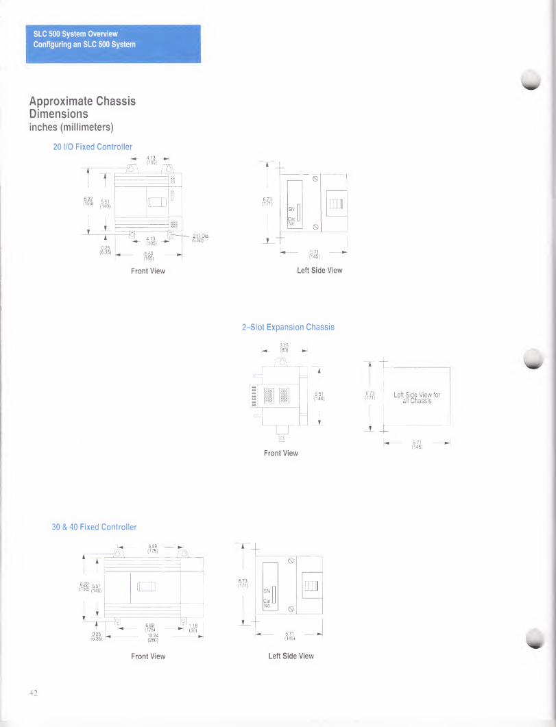
Approximate Chassis Dimensions inches (millimeters)
20 I/O Fixed Controller
2-Slot Expansion Chassis
t 5.51 (140)
1
T 6.73 (171)
Left Side View for all Chassis
5.71 (145)
30 & 40 Fixed Controller
)m
0.25 (6.35)
:JZ\ 6.89 (175)
6.89 (175)
10.24 (260)
P 1.18 (30)
Front View Left Side View
42
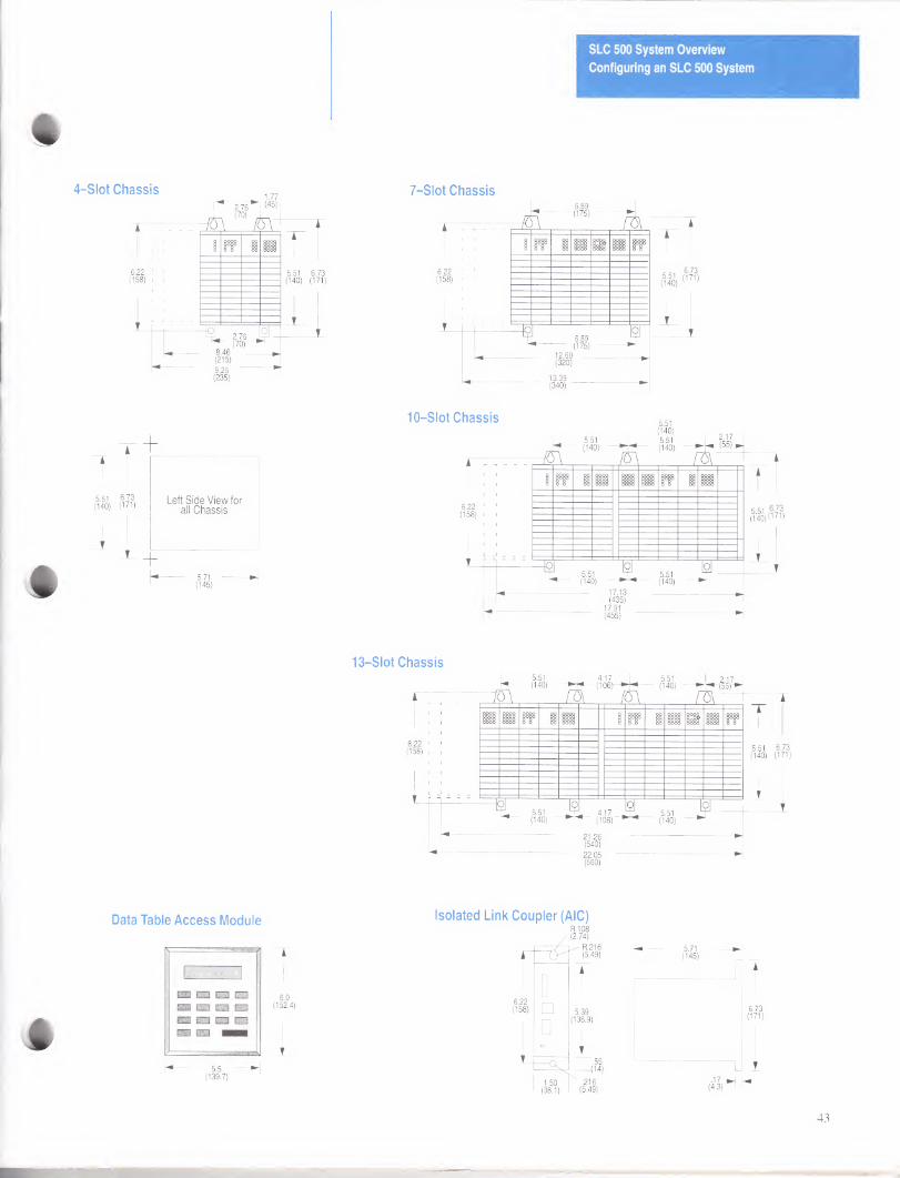
SLC 500 System Overview
Configuring an SLC 500 System
T 5.51 (140)
1
Left Side View for all Chassis
5.71 (145)
7-Slot Chassis
10-Slot Chassis
13-Slot Chassis
Data Table Access Module
6.0 (152.4)
Isolated Link Coupler (AIC)
6.22 (158) □
□
1.50 (38.1)
R.108 (2.74)
R.216 —J ri.ziD (5.49)
5.39 (136.9)
.55 -(14)
' .216 (5.49)
43
SLC 500 System Overview
Configuring an SLC 500 System
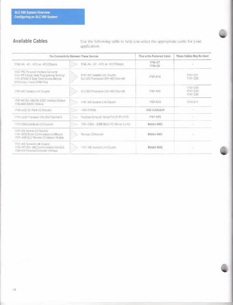
Available Cables Use the following table to help you select the appropriate cable for your application.
For Connectivity Between These Devices This is the Preferred Cable These Cables May Be Used
1746-A4, -A7, -A10, or-A13 Chassis > 1746-A4, -A7, -A10, or -A13 Chassis 1746-C7
1746-C9 -
1747-PIC Personal Interface Converter
1747-PT1 Hand-Held Programming Terminal
1747-DTAM-E Data Table Access Module
2707-Lxxx, -Vxxx DTAM Plus
x 1747—AIC Isolated Link Coupler
/ SLC 500 Processors (DH-485 Channel) 1747—Cl 0
1747—C11
1747-C20
1747—AIC Isolated Link Coupler SLC 500 Processors (DH-485 Channel) 1747-C11
1747—Cl 0
1747—Cl 3
1747-C20
1747-KE DH-485/RS-232C Interface Module
1746-BAS BASIC Module 1747—AIC Isolated Link Coupler 1747—Cl 3 1747-C11
1746-xx32 32-Point I/O Modules Spi^ 1492-1 FM40x 1492-CABLExH -
1747-L532 Processor (RS-232 Channel 0) > Personal Computer Serial Port (9-Pin DTE) 1747-CP3 -
1747-DSN Distributed I/O Scanner pX 1791—IOBA, -IOBB Block I/O (Series A only) Belden 9463 -
1747-SN Remote I/O Scanner
1747-DCM Direct Communications Module
1747-ASB SLC Remote I/O Adapter Module
Remote I/O Network Belden 9463 -
1747—AIC Isolated Link Coupler
1770-KF3 DH-485 Communication Interface
1784-KR Personal Computer Interface
1747—AIC Isolated Link Coupler Belden 9842 -
44
Publications
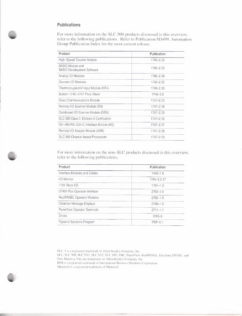
For more information on the SLC 500 products discussed in this overview, refer to the following publications. Refer to Publication SD499, Automation Group Publication Index for the most current release.
Product Publication
High-Speed Counter Module 1746-2.32
BASIC Module and
BASIC Development Software 1746-2.33
Analog I/O Modules 1746-2.34
Discrete I/O Modules 1746-2.35
Thermocouple/mV Input Module (NT4) 1746-2.36
Bulletin 1746-1747 Price Sheet 1746-3.0
Direct Communications Module 1747-2.33
Remote I/O Scanner Module (SN) 1747-2.34
Distributed I/O Scanner Module (DSN) 1747-2.35
SLC 500 Class I, Division 2 Certification 1747-2.36
DH-485/RS-232-C Interface Module (KE) 1747-2.37
Remote I/O Adapter Module (ASB) 1747-2.38
SLC 500 Chassis-based Processors 1747-2.39
For more information on the non-SLC products discussed in this overview, refer to the following publications.
Product Publication
Interface Modules and Cables 1492-1.6
I/O Monitor 1784-6.5.17
1791 Block I/O 1791-1.3
DTAM Plus Operator Interface 2702-2.0
RediPANEL Operator Modules 2705-1.0
Dataliner Message Displays 2706-1.0
PanelView Operator Terminals 2711-1.1
Drives DHQ-6
Pyramid Solutions Program PSP-5.1
PLC-5 is a registered trademark of Allen-Bradley Company, Inc.
SLC, SLC 500, SLC 5/01, SLC 5/02, SLC 5/03, IMC, Panel View, RediPANEL, Dataliner, DTAM, and Data Highway Plus are trademarks of Allen-Bradley Company, Inc.
IBM is a registered trademark of International Business Machines Corporation.
Microsoft is a registered trademark of Microsoft.

ALLEN-BRADLEY A RDIIKWELL INTERNATIONAL COMPANY
With major offices worldwide.
Allen-Bradley has been helping its customers improve productivity and quality for 90 years.
A-B designs, manufactures and supports a broad range of control and automation products
worldwide. They include logic processors, power and motion control devices, man-machine
interfaces and sensors. Allen-Bradley is a subsidiary of Rockwell International, one of the
world’s leading technology companies.
Algeria • Argentina • Australia • Austria • Bahrain • Belgium • Brazil • Bulgaria • Canada • Chile • China, PRC • Colombia • Costa Rica • Croatia • Cyprus • Czech Republic •
Denmark • Ecuador • Egypt • El Salvador • Finland • France • Germany • Greece • Guatemala • Honduras • Hong Kong • Hungary • Iceland • India • Indonesia • Israel • Italy
• Jamaica • Japan • Jordan • Korea • Kuwait • Lebanon • Malaysia • Mexico • New Zealand • Norway • Oman • Pakistan • Peru • Philippines • Poland • Portugal • Puerto
Rico • Qatar • Romania • Russia-CIS • Saudi Arabia • Singapore • Slovakia • Slovenia • South Africa, Republic • Spain • Switzerland • Taiwan • Thailand • The Netherlands
• Turkey • United Arab Emirates • United Kingdom • United States • Uruguay • Venezuela • Yugoslavia ^9
World Headquarters, Allen-Bradley, 1201 South Second Street, Milwaukee, Wl 53204 USA, Tel: (1) 414 382-2000 Fax: (1) 414 382-4444
Publication 1747-2.30 August 1993 Supersedes Publication 1747-2.30 dated April 1992 ©1993 Aiien-Bradiey Company, inc