Embed Size (px)
Citation preview
The ADT
SLC
Signaling Line Circuit
Manual
One Town Center RoadBoca Raton, FL 33431(561) 988-3600FAX: (561) 988-3675
Security Services Inc.
Document 51348
8/29/00 Revision: APN 51348:A ECN 00-394

Prec
AndeingcaSupro
ThtorrecPrmatheof chgegoassiganmafun
Smrearooalsingfirs
Pamaca
•
•
•
•
Thsmvacrede
Smlimchfireizinbeentyptor
Smwamaexfla
e.
-
s-i-
.r-
il-
y
-
r-
e
o-
F
automatic fire alarm system–typically made up of smoketectors, heat detectors, manual pull stations, audible warn- devices, and a fire alarm control with remote notification
pability–can provide early warning of a developing fire.ch a system, however, does not assure protection againstperty damage or loss of life resulting from a fire.
e Manufacturer recommends that smoke and/or heat detec-s be located throughout a protected premise following theommendations of the current edition of the National Fire
otection Association Standard 72 (NFPA 72),nufacturer's recommendations, State and local codes, and recommendations contained in the Guide for Proper UseSystem Smoke Detectors, which is made available at noarge to all installing dealers. A study by the Federal Emer-ncy Management Agency (an agency of the United Statesvernment) indicated that smoke detectors may not go off in many as 35% of all fires. While fire alarm systems are de-ned to provide early warning against fire, they do not guar-tee warning or protection against fire. A fire alarm systemy not provide timely or adequate warning, or simply may notction, for a variety of reasons:
oke detectors may not sense fire where smoke cannotch the detectors such as in chimneys, in or behind walls, onfs, or on the other side of closed doors. Smoke detectorso may not sense a fire on another level or floor of a build-. A second-floor detector, for example, may not sense at-floor or basement fire.
rticles of combustion or "smoke" from a developing firey not reach the sensing chambers of smoke detectors be-
use:
Barriers such as closed or partially closed doors, walls, orchimneys may inhibit particle or smoke flow.
Smoke particles may become "cold," stratify, and not reachthe ceiling or upper walls where detectors are located.
Smoke particles may be blown away from detectors by airoutlets.
Smoke detectors may be drawn into air returns beforereaching the detector.
e amount of "smoke" present may be insufficient to alarmoke detectors. Smoke detectors are designed to alarm atrious levels of smoke density. If such density levels are notated by a developing fire at the location of detectors, the
tectors will not go into alarm.
oke detectors, even when working properly, have sensingitations. Detectors that have photoelectronic sensingambers tend to detect smoldering fires better than flamings, which have little visible smoke. Detectors that have ion-g-type sensing chambers tend to detect fast-flaming fires
tter than smoldering fires. Because fires develop in differ-t ways and are often unpredictable in their growth, neithere of detector is necessarily best and a given type of detec- may not provide adequate warning of a fire.
oke detectors cannot be expected to provide adequaterning of fires caused by arson, children playing withtches (especially in bedrooms), smoking in bed, and violent
plosions (caused by escaping gas, improper storage ofmmable materials, etc.).
Heat detectors do not sense particles of combustion andalarm only when heat on their sensors increases at a prede-termined rate or reaches a predetermined level. Rate-of-riseheat detectors may be subject to reduced sensitivity over timFor this reason, the rate-of-rise feature of each detectorshould be tested at least once per year by a qualified fire protection specialist. Heat detectors are designed to protectproperty, not life.
IMPORTANT! Smoke detectors must be installed in thesame room as the control panel and in rooms used by the sytem for the connection of alarm transmission wiring, communcations, signaling, and/or power. If detectors are not so lo-cated, a developing fire may damage the alarm system, crip-pling its ability to report a fire.
Audible warning devices such as bells may not alert peopleif these devices are located on the other side of closed orpartly open doors or are located on another floor of a buildingAny warning device may fail to alert people with a disability othose who have recently consumed drugs, alcohol or medication. Please note that:
• Strobes can, under certain circumstances, cause seizuresin people with conditions such as epilepsy.
• Studies have shown that certain people, even when theyhear a fire alarm signal, do not respond or comprehend themeaning of the signal. It is the property owner's responsibity to conduct fire drills and other training exercise to makepeople aware of fire alarm signals and instruct them on theproper reaction to alarm signals.
• In rare instances, the sounding of a warning device cancause temporary or permanent hearing loss.
A fire alarm system will not operate without any electricalpower. If AC power fails, the system will operate from standbbatteries only for a specified time and only if the batterieshave been properly maintained and replaced regularly.
Equipment used in the system may not be technically com-patible with the control. It is essential to use only equipmentlisted for service with your control panel.
Telephone lines needed to transmit alarm signals from apremise to a central monitoring station may be out of serviceor temporarily disabled. For added protection against tele-phone line failure, backup radio transmission systems are recommended.
The most common cause of fire alarm malfunction is inade-quate maintenance. To keep the entire fire alarm system inexcellent working order, ongoing maintenance is required pethe manufacturer's recommendations, and UL and NFPA standards. At a minimum, the requirements of Chapter 7 of NFPA72 shall be followed. Environments with large amounts ofdust, dirt or high air velocity require more frequent mainte-nance. A maintenance agreement should be arrangedthrough the local manufacturer's representative. Maintenancshould be scheduled monthly or as required by National and/or local fire codes and should be performed by authorized prfessional fire alarm installers only. Adequate written recordsof all inspections should be kept.
While a fire alarm system may lower insurancerates, it is not a substitute for fire insurance!ire Alarm System Limitations
au-Lg.p65 01/18/2000
WAneof memoDoma
CAChmuanwadittio
AlltioIn endirvicfie
Th0-4cosymaananna
Veindtha
t-
i-
-
,ei-
p
In
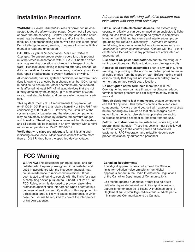
RNING - Several different sources of power can be con-cted to the fire alarm control panel. Disconnect all sourcespower before servicing. Control unit and associated equip-nt may be damaged by removing and/or inserting cards,dules, or interconnecting cables while the unit is energized. not attempt to install, service, or operate this unit until thisnual is read and understood.
UTION - System Reacceptance Test after Softwareanges. To ensure proper system operation, this productst be tested in accordance with NFPA 72 Chapter 7 aftery programming operation or change in site-specific soft-re. Reacceptance testing is required after any change, ad-ion or deletion of system components, or after any modifica-n, repair or adjustment to system hardware or wiring.
components, circuits, system operations, or software func-ns known to be affected by a change must be 100% tested.addition, to ensure that other operations are not inadvert-tly affected, at least 10% of initiating devices that are notectly affected by the change, up to a maximum of 50 de-es, must also be tested and proper system operation veri-d.
is system meets NFPA requirements for operation at9° C/32-120° F and at a relative humidity of 85% RH (non-
ndensing) at 30° C/86° F. However, the useful life of thestem's standby batteries and the electronic componentsy be adversely affected by extreme temperature rangesd humidity. Therefore, it is recommended that this systemd all peripherals be installed in an environment with a nomi-l room temperature of 15-27° C/60-80° F.
rify that wire sizes are adequate for all initiating andicating device loops. Most devices cannot tolerate moren a 10% I.R. drop from the specified device voltage.
Like all solid state electronic devices, this system mayoperate erratically or can be damaged when subjected to lighning-induced transients. Although no system is completelyimmune from lightning transients and interferences, propergrounding will reduce susceptibility. Overhead or outsideaerial wiring is not recommended, due to an increased sus-ceptibility to nearby lightning strikes. Consult with the Techncal Services Department if any problems are anticipated orencountered.
Disconnect AC power and batteries prior to removing or inserting circuit boards. Failure to do so can damage circuits.
Remove all electronic assemblies prior to any drilling, filingreaming, or punching of the enclosure. When possible, makall cable entries from the sides or rear. Before making modifcations, verify that they will not interfere with battery, trans-former, and printed circuit board location.
Do not tighten screw terminals more than 9 in-lbs.Over-tightening may damage threads, resulting in reducedterminal contact pressure and difficulty with screw terminalremoval.
Though designed to last many years, system componentscan fail at any time. This system contains static-sensitivecomponents. Always ground yourself with a proper wrist strabefore handling any circuits so that static charges are re-moved from the body. Use static-suppressive packagingto protect electronic assemblies removed from the unit.
Follow the instructions in the installation, operating, andprogramming manuals. These instructions must be followedto avoid damage to the control panel and associatedequipment. FACP operation and reliability depend uponproper installation by authorized personnel.
Adherence to the following will aid in problem-freeinstallation with long-term reliability:
WARNING: This equipment generates, uses, and canradiate radio frequency energy and if not installed andused in accordance with the instruction manual, maycause interference to radio communications. It hasbeen tested and found to comply with the limits for classA computing device pursuant to Subpart B of Part 15 ofFCC Rules, which is designed to provide reasonableprotection against such interference when operated in acommercial environment. Operation of this equipment ina residential area is likely to cause interference, in whichcase the user will be required to correct the interferenceat his own expense.
Canadian RequirementsThis digital apparatus does not exceed the Class Alimits for radiation noise emissions from digitalapparatus set out in the Radio Interference Regulationsof the Canadian Department of Communications.
Le present appareil numerique n'emet pas de bruitsradioelectriques depassant les limites applicables auxappareils numeriques de la classe A prescrites dans leReglement sur le brouillage radioelectrique edicte par leministere des Communications du Canada.
FCC Warning
stallation Precautions
Precau-Lg.p65 01/18/2000

This Page Intentionally Left Blank
4 ADT SLC Manual 51348:A 8/29/00
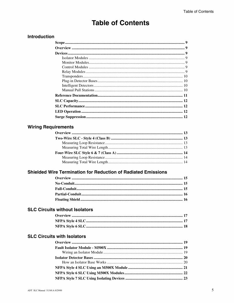
Table of Contents
Table of Contents
IntroductionScope............................................................................................................................. 9Overview ...................................................................................................................... 9Devices .......................................................................................................................... 9
Isolator Modules .................................................................................................... 9Monitor Modules.................................................................................................... 9Control Modules .................................................................................................... 9Relay Modules ....................................................................................................... 9Transponders........................................................................................................ 10Plug-in Detector Bases......................................................................................... 10Intelligent Detectors ............................................................................................. 10Manual Pull Stations ............................................................................................ 10
Reference Documentation......................................................................................... 11SLC Capacity............................................................................................................. 12SLC Performance...................................................................................................... 12LED Operation .......................................................................................................... 12Surge Suppression ..................................................................................................... 12
Wiring RequirementsOverview .................................................................................................................... 13Two-Wire SLC - Style 4 (Class B) ........................................................................... 13
Measuring Loop Resistance ................................................................................. 13Measuring Total Wire Length.............................................................................. 13
Four-Wire SLC Style 6 & 7 (Class A) ..................................................................... 14Measuring Loop Resistance ................................................................................. 14Measuring Total Wire Length.............................................................................. 14
Shielded Wire Termination for Reduction of Radiated EmissionsOverview .................................................................................................................... 15No-Conduit................................................................................................................. 15Full-Conduit............................................................................................................... 15Partial-Conduit.......................................................................................................... 16Floating Shield ........................................................................................................... 16
SLC Circuits without IsolatorsOverview .................................................................................................................... 17NFPA Style 4 SLC..................................................................................................... 17NFPA Style 6 SLC..................................................................................................... 18
SLC Circuits with IsolatorsOverview .................................................................................................................... 19Fault Isolator Module - M500X ............................................................................... 19
Wiring an Isolator Module ................................................................................... 19
Isolator Detector Bases ............................................................................................. 20How an Isolator Base Works ............................................................................... 20
NFPA Style 4 SLC Using an M500X Module ......................................................... 21NFPA Style 6 SLC Using M500X Modules............................................................. 22NFPA Style 7 SLC Using Isolating Devices ............................................................ 23
ADT SLC Manual 51348:A 8/29/00 5
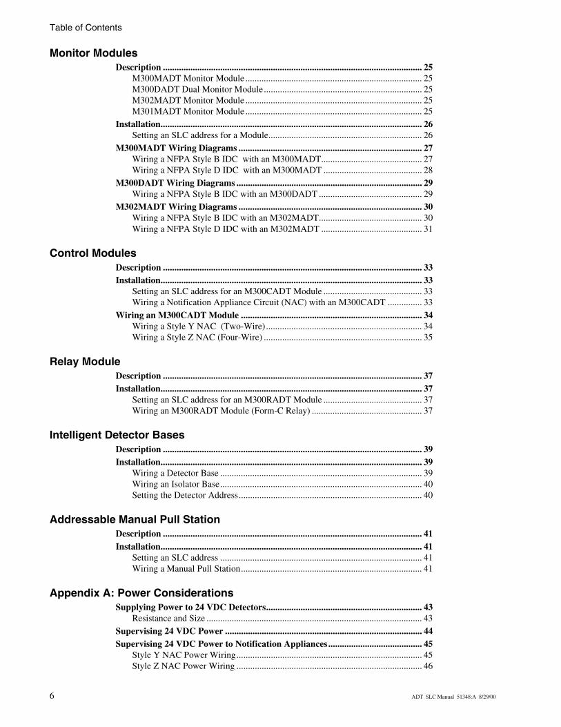
Table of Contents
Monitor ModulesDescription ................................................................................................................. 25
M300MADT Monitor Module ............................................................................. 25M300DADT Dual Monitor Module..................................................................... 25M302MADT Monitor Module ............................................................................. 25M301MADT Monitor Module ............................................................................. 25
Installation.................................................................................................................. 26Setting an SLC address for a Module................................................................... 26
M300MADT Wiring Diagrams ................................................................................ 27Wiring a NFPA Style B IDC with an M300MADT............................................ 27Wiring a NFPA Style D IDC with an M300MADT ........................................... 28
M300DADT Wiring Diagrams ................................................................................. 29Wiring a NFPA Style B IDC with an M300DADT ............................................. 29
M302MADT Wiring Diagrams ................................................................................ 30Wiring a NFPA Style B IDC with an M302MADT............................................. 30Wiring a NFPA Style D IDC with an M302MADT ............................................ 31
Control ModulesDescription ................................................................................................................. 33Installation.................................................................................................................. 33
Setting an SLC address for an M300CADT Module ........................................... 33Wiring a Notification Appliance Circuit (NAC) with an M300CADT ............... 33
Wiring an M300CADT Module ............................................................................... 34Wiring a Style Y NAC (Two-Wire).................................................................... 34Wiring a Style Z NAC (Four-Wire) ..................................................................... 35
Relay ModuleDescription ................................................................................................................. 37Installation.................................................................................................................. 37
Setting an SLC address for an M300RADT Module ........................................... 37Wiring an M300RADT Module (Form-C Relay) ................................................ 37
Intelligent Detector BasesDescription ................................................................................................................. 39Installation.................................................................................................................. 39
Wiring a Detector Base ........................................................................................ 39Wiring an Isolator Base........................................................................................ 40Setting the Detector Address................................................................................ 40
Addressable Manual Pull StationDescription ................................................................................................................. 41Installation.................................................................................................................. 41
Setting an SLC address ........................................................................................ 41Wiring a Manual Pull Station............................................................................... 41
Appendix A: Power ConsiderationsSupplying Power to 24 VDC Detectors.................................................................... 43
Resistance and Size .............................................................................................. 43
Supervising 24 VDC Power ...................................................................................... 44Supervising 24 VDC Power to Notification Appliances......................................... 45
Style Y NAC Power Wiring................................................................................. 45Style Z NAC Power Wiring ................................................................................. 46
6 ADT SLC Manual 51348:A 8/29/00
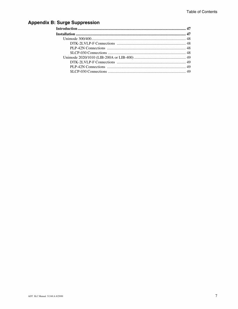
Table of Contents
Appendix B: Surge SuppressionIntroduction ............................................................................................................... 47Installation ................................................................................................................. 47
Unimode 300/400................................................................................................. 48DTK-2LVLP-F Connections ....................................................................... 48PLP-42N Connections ................................................................................. 48SLCP-030 Connections ................................................................................ 48
Unimode 2020/1010 (LIB-200A or LIB-400) ..................................................... 49DTK-2LVLP-F Connections ....................................................................... 49PLP-42N Connections ................................................................................. 49SLCP-030 Connections ................................................................................ 49
ADT SLC Manual 51348:A 8/29/00 7

This Page Intentionally Left Blank
8 ADT SLC Manual 51348:A 8/29/00
Introduction
ScopeThis document covers the installation and wiring of various Signaling Line Circuit (SLC) devices, when used with the following ADT Fire Alarm Control Panels:
This document also provides basic information that applies to ADT SLC loops in general, such as the branch resistance measurements.
Additional information about each control panel and the modules and detectors referenced in this document can be found in the respective installation manual as listed in Table 1, “Reference Documentation,” on page 11.
OverviewCommunication between the control panel and intelligent and addressable initiating, monitor, and control devices takes place through a Signaling Line Circuit (SLC), which can be wired to meet the requirements of NFPA Style 4, Style 6, or Style 7.
Devices
Isolator Modules
Isolator Modules permit a zone of detectors and modules to be fault isolated from the remainder of the SLC loop, allowing critical components to function in the event of a circuit fault. Isolator modules are required to meet the requirements of an NFPA Style 7 circuit.
Monitor Modules
These addressable modules allow the control panel to monitor entire circuits of conventional alarm initiating devices, such as manual pull stations, smoke detectors, heat detectors, waterflow and supervisory devices.
Control Modules
Through these addressable modules, the control panel can selectively activate Notification Appliance Circuits (NAC).
Relay Modules
This addressable module provides the control panel with a dry-contact output for activating a variety of auxiliary devices.
Unimode 2020/1010 Unimode II w/ AIM
Unimode 300/400
ADT SLC Manual 51348:A 8/29/00 9

Introduction Devices
Transponders
ADT-XP5-M - Supervises five Class-B addressable Initiating Device Circuits which monitor normally open contact initiating devices.
ADT-XP5-C - Acts as a NAC or a speaker/telephone circuit (Class B only) or a Form-C relay.
XP Series - (XPP-1, XPC-8, XPM-8 & XPZ-8) Provides the FACP with an efficient multiplex subsystem capability. It communicates with the FACP and functions as a data-gathering panel for alarm Initiating Device Circuits (IDC) and as a remote switching center for Notification Appliance Circuits (NAC), telephone circuits or relays.
For information on connecting these transponders to the SLC, refer to the ADT XP5 Series Manual or the ADT XP Transponder Manual.
Plug-in Detector Bases
These bases provide a connection between the SLC and a variety of intelligent detectors which are snapped into place. Standard bases and isolator bases are used depending upon which NFPA SLC style is required. Standard and isolator bases are used depending upon which NFPA SLC style is required. Sounder and relay bases are similar to standard bases, but have sound or relay capabilities.
Standard Base - Models B501(standard small diameter base) and B710LP (standard large diameter base)
Isolator Base - Model B224BI isolator base
Sounder Base - Models B501BH (standard sounder base) and B501BHT (base with temporal sounder)
Relay Base - Model B224RB relay base
Intelligent Detectors
1351ADT - Analog, addressable, low profile intelligent smoke detector that incorporates an ionization sensing chamber. Designed to provide open area protection.
2351ADT - Same as 1351ADT, but uses a photoelectric sensing chamber. The 2351TADT adds thermal sensors that will alarm at a fixed temperature of 135° F. Designed to provide open area protection.
5351ADT - Intelligent thermistor sensing circuit for fast response. Designed to provide open area protection with 50 foot spacing capability. The 5351RADT incorporates a thermal rate of rise of 15°F (9.4°C).
DH300PADT - Photoelectric smoke detector designed to detect smoke in an air duct. Model DH300PRADT contains housing and relay.
Manual Pull Stations
When activated, provides an addressable location to the control panel.
10 ADT SLC Manual 51348:A 8/29/00
Reference Documentation Introduction
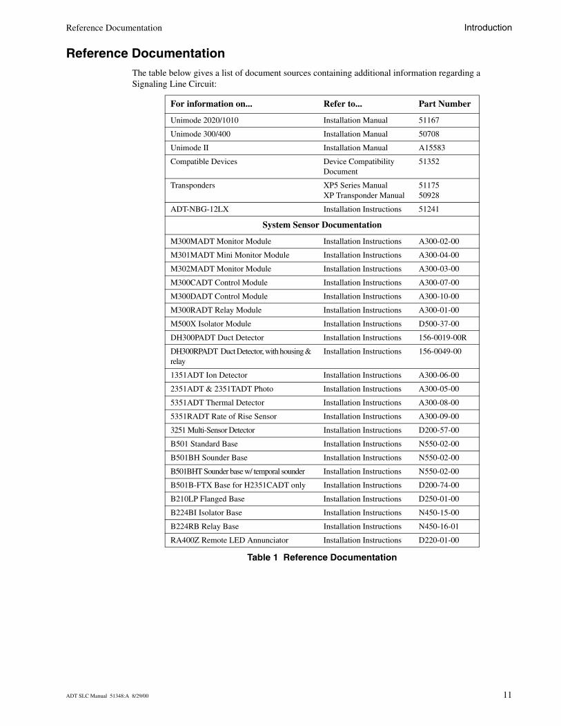
Reference DocumentationThe table below gives a list of document sources containing additional information regarding a Signaling Line Circuit:
Table 1 Reference Documentation
For information on... Refer to... Part Number
Unimode 2020/1010 Installation Manual 51167
Unimode 300/400 Installation Manual 50708
Unimode II Installation Manual A15583
Compatible Devices Device Compatibility Document
51352
Transponders XP5 Series ManualXP Transponder Manual
5117550928
ADT-NBG-12LX Installation Instructions 51241
System Sensor Documentation
M300MADT Monitor Module Installation Instructions A300-02-00
M301MADT Mini Monitor Module Installation Instructions A300-04-00
M302MADT Monitor Module Installation Instructions A300-03-00
M300CADT Control Module Installation Instructions A300-07-00
M300DADT Control Module Installation Instructions A300-10-00
M300RADT Relay Module Installation Instructions A300-01-00
M500X Isolator Module Installation Instructions D500-37-00
DH300PADT Duct Detector Installation Instructions 156-0019-00R
DH300RPADT Duct Detector, with housing & relay
Installation Instructions 156-0049-00
1351ADT Ion Detector Installation Instructions A300-06-00
2351ADT & 2351TADT Photo Installation Instructions A300-05-00
5351ADT Thermal Detector Installation Instructions A300-08-00
5351RADT Rate of Rise Sensor Installation Instructions A300-09-00
3251 Multi-Sensor Detector Installation Instructions D200-57-00
B501 Standard Base Installation Instructions N550-02-00
B501BH Sounder Base Installation Instructions N550-02-00
B501BHT Sounder base w/ temporal sounder Installation Instructions N550-02-00
B501B-FTX Base for H2351CADT only Installation Instructions D200-74-00
B210LP Flanged Base Installation Instructions D250-01-00
B224BI Isolator Base Installation Instructions N450-15-00
B224RB Relay Base Installation Instructions N450-16-01
RA400Z Remote LED Annunciator Installation Instructions D220-01-00
ADT SLC Manual 51348:A 8/29/00 11
Introduction SLC Capacity
SLC CapacityThe individual control panel determines the capacity of devices that can be incorporated into an SLC. See the specific installation manual for this information.
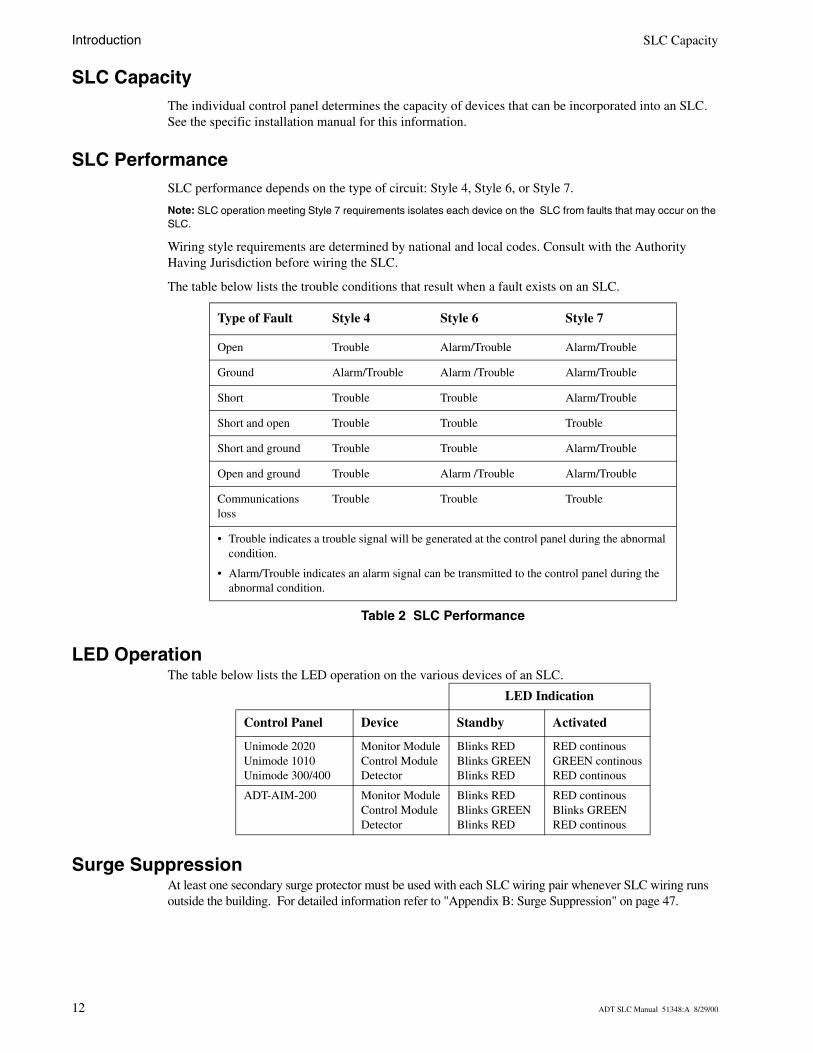
SLC PerformanceSLC performance depends on the type of circuit: Style 4, Style 6, or Style 7.
Note: SLC operation meeting Style 7 requirements isolates each device on the SLC from faults that may occur on the SLC.
Wiring style requirements are determined by national and local codes. Consult with the Authority Having Jurisdiction before wiring the SLC.
The table below lists the trouble conditions that result when a fault exists on an SLC.
Table 2 SLC Performance
LED OperationThe table below lists the LED operation on the various devices of an SLC.
Surge SuppressionAt least one secondary surge protector must be used with each SLC wiring pair whenever SLC wiring runs outside the building. For detailed information refer to "Appendix B: Surge Suppression" on page 47.
Type of Fault Style 4 Style 6 Style 7
Open Trouble Alarm/Trouble Alarm/Trouble
Ground Alarm/Trouble Alarm /Trouble Alarm/Trouble
Short Trouble Trouble Alarm/Trouble
Short and open Trouble Trouble Trouble
Short and ground Trouble Trouble Alarm/Trouble
Open and ground Trouble Alarm /Trouble Alarm/Trouble
Communications loss
Trouble Trouble Trouble
• Trouble indicates a trouble signal will be generated at the control panel during the abnormal condition.
• Alarm/Trouble indicates an alarm signal can be transmitted to the control panel during the abnormal condition.
LED Indication
Control Panel Device Standby Activated
Unimode 2020Unimode 1010Unimode 300/400
Monitor ModuleControl ModuleDetector
Blinks REDBlinks GREENBlinks RED
RED continousGREEN continousRED continous
ADT-AIM-200 Monitor ModuleControl ModuleDetector
Blinks REDBlinks GREENBlinks RED
RED continousBlinks GREENRED continous
12 ADT SLC Manual 51348:A 8/29/00
Wiring Requirements
OverviewIt is recommended that all SLC wiring be twisted shielded pair to minimize the effects of electrical interference except when using the LIB-200A or LIB-400 where non-shielded wire is recommended.
Wire size should be no smaller than 18 AWG (1.0 mm2) and no larger than 12 AWG (3.25 mm2) wire.
Two-Wire SLC - Style 4 (Class B)
Measuring Loop Resistance
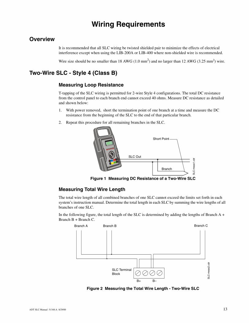
T-tapping of the SLC wiring is permitted for 2-wire Style 4 configurations. The total DC resistance from the control panel to each branch end cannot exceed 40 ohms. Measure DC resistance as detailed and shown below:
1. With power removed, short the termination point of one branch at a time and measure the DC resistance from the beginning of the SLC to the end of that particular branch.
2. Repeat this procedure for all remaining branches in the SLC.
Figure 1 Measuring DC Resistance of a Two-Wire SLC
Measuring Total Wire Length
The total wire length of all combined branches of one SLC cannot exceed the limits set forth in each system’s instruction manual. Determine the total length in each SLC by summing the wire lengths of all branches of one SLC.
In the following figure, the total length of the SLC is determined by adding the lengths of Branch A + Branch B + Branch C.
Figure 2 Measuring the Total Wire Length - Two-Wire SLC
SLC
-mea
s1.c
dr
SLC Out
Branch
Short Point
Branch A Branch B Branch C
SLC
-mea
s2.c
dr
SLC Terminal Block
B+ B–
ADT SLC Manual 51348:A 8/29/00 13
Wiring Requirements Four-Wire SLC Style 6 & 7 (Class A)
Four-Wire SLC Style 6 & 7 (Class A)
Measuring Loop Resistance
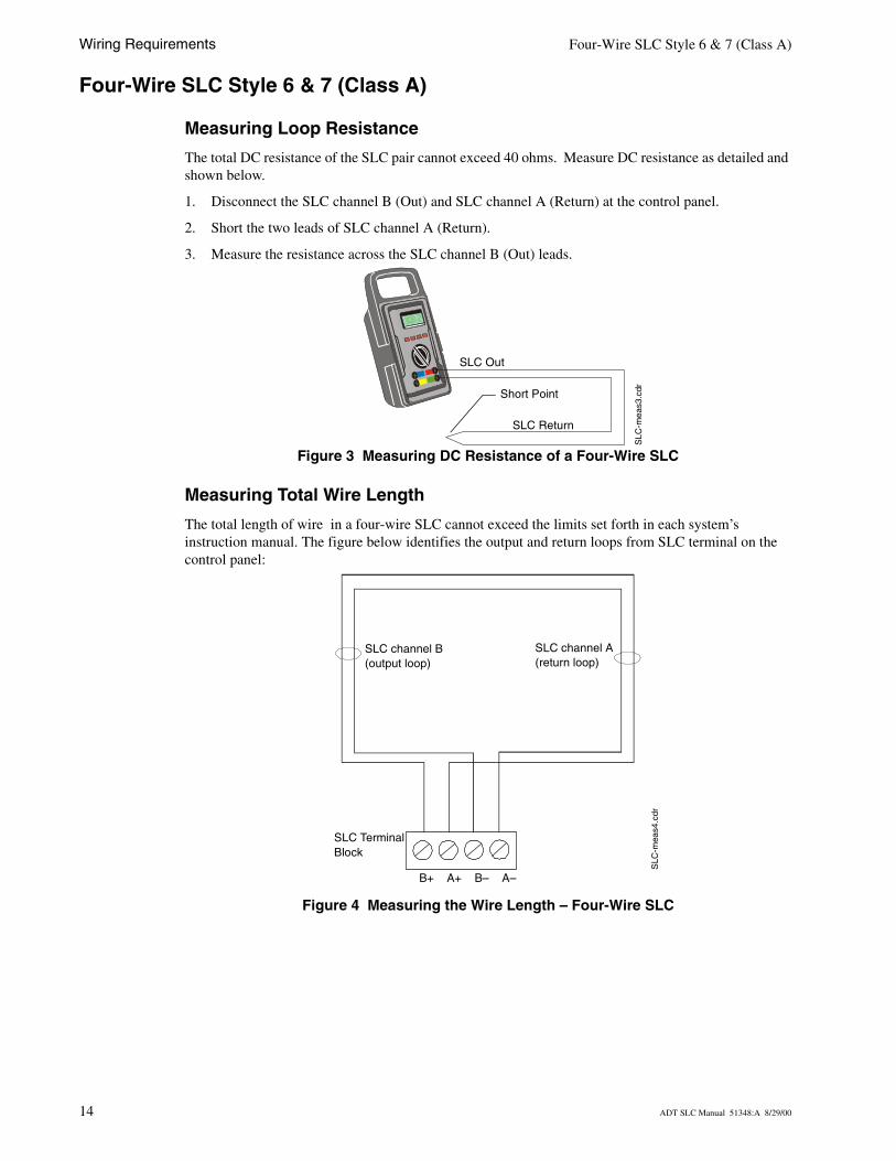
The total DC resistance of the SLC pair cannot exceed 40 ohms. Measure DC resistance as detailed and shown below.
1. Disconnect the SLC channel B (Out) and SLC channel A (Return) at the control panel.
2. Short the two leads of SLC channel A (Return).
3. Measure the resistance across the SLC channel B (Out) leads.
Figure 3 Measuring DC Resistance of a Four-Wire SLC
Measuring Total Wire Length
The total length of wire in a four-wire SLC cannot exceed the limits set forth in each system’s instruction manual. The figure below identifies the output and return loops from SLC terminal on the control panel:
Figure 4 Measuring the Wire Length – Four-Wire SLC
SLC
-mea
s3.c
dr
SLC Out
SLC Return
Short Point
SLC
-mea
s4.c
drSLC channel B (output loop)
SLC channel A (return loop)
SLC Terminal Block
B+ A+ B– A–
14 ADT SLC Manual 51348:A 8/29/00
Shielded Wire Termination for Reduction of Radiated Emissions
OverviewThe drawings below show four methods of proper termination of the shield, depending on the type of conduit used:
• No-conduit• Full-conduit• Partial-conduit• Floating Shield
Shielding of the SLC is not recommended in all applications. Refer to the “Floating Shield” section for specific instances where it is not recommended.
Use of good wiring practice consistent with local electrical codes is expected.
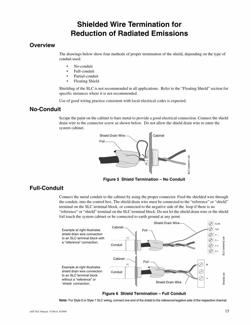
No-ConduitScrape the paint on the cabinet to bare metal to provide a good electrical connection. Connect the shield drain wire to the connector screw as shown below. Do not allow the shield drain wire to enter the system cabinet.
Figure 5 Shield Termination – No Conduit
Full-ConduitConnect the metal conduit to the cabinet by using the proper connector. Feed the shielded wire through the conduit, into the control box. The shield drain wire must be connected to the “reference” or “shield” terminal on the SLC terminal block, or connected to the negative side of the loop if there is no “reference” or “shield” terminal on the SLC terminal block. Do not let the shield drain wire or the shield foil touch the system cabinet or be connected to earth ground at any point.
Figure 6 Shield Termination – Full Conduit
Note: For Style 6 or Style 7 SLC wiring, connect one end of the shield to the reference/negative side of the respective channel.
Shield Drain Wire
SLC
-sw
term
1.cd
r
Cabinet
Foil
CabinetS
LC-s
wte
rm2.
cdr
Shield Drain Wire
FoilExample at right illustrates shield drain wire connection to an SLC terminal block with a “reference” connection.
Example at right illustrates shield drain wire connection to an SLC terminal block without a “reference” or “shield connection. S
hiel
d2.c
dr
Cabinet
Shield Drain Wire
Foil
Conduit
Conduit
+
-
ADT SLC Manual 51348:A 8/29/00 15
Shielded Wire Termination for Reduction of Radiated Emissions Partial-Conduit
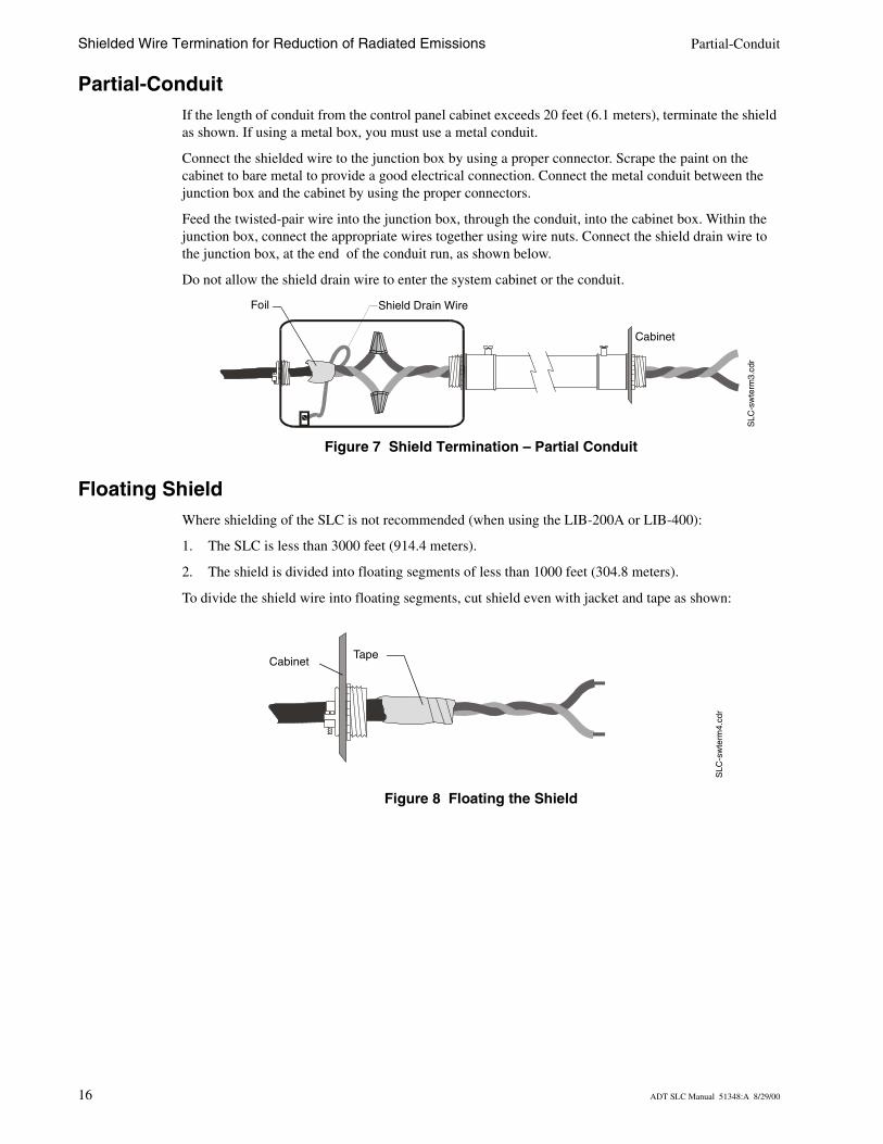
Partial-ConduitIf the length of conduit from the control panel cabinet exceeds 20 feet (6.1 meters), terminate the shield as shown. If using a metal box, you must use a metal conduit.
Connect the shielded wire to the junction box by using a proper connector. Scrape the paint on the cabinet to bare metal to provide a good electrical connection. Connect the metal conduit between the junction box and the cabinet by using the proper connectors.
Feed the twisted-pair wire into the junction box, through the conduit, into the cabinet box. Within the junction box, connect the appropriate wires together using wire nuts. Connect the shield drain wire to the junction box, at the end of the conduit run, as shown below.
Do not allow the shield drain wire to enter the system cabinet or the conduit.
Figure 7 Shield Termination – Partial Conduit
Floating ShieldWhere shielding of the SLC is not recommended (when using the LIB-200A or LIB-400):
1. The SLC is less than 3000 feet (914.4 meters).
2. The shield is divided into floating segments of less than 1000 feet (304.8 meters).
To divide the shield wire into floating segments, cut shield even with jacket and tape as shown:
Figure 8 Floating the Shield
Cabinet
Shield Drain WireFoil
SLC
-sw
term
3.cd
r
SLC
-sw
term
4.cd
r
TapeCabinet
16 ADT SLC Manual 51348:A 8/29/00
SLC Circuits without Isolators
OverviewThis chapter concerns itself with the two styles of circuits that do not require isolation devices:
• NFPA Style 4• NFPA Style 6
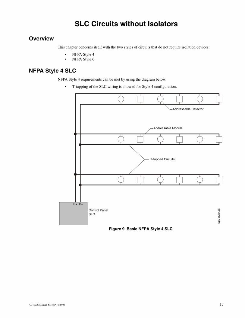
NFPA Style 4 SLCNFPA Style 4 requirements can be met by using the diagram below.
• T-tapping of the SLC wiring is allowed for Style 4 configuration.
Figure 9 Basic NFPA Style 4 SLC
SLC
-sty
le4.
cdr
Addressable Detector
Addressable Module
T-tapped Circuits
Control PanelSLC
B+ B–
ADT SLC Manual 51348:A 8/29/00 17
SLC Circuits without Isolators NFPA Style 6 SLC
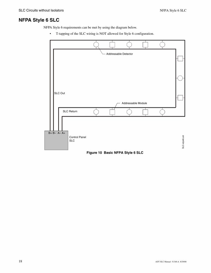
NFPA Style 6 SLCNFPA Style 6 requirements can be met by using the diagram below.
• T-tapping of the SLC wiring is NOT allowed for Style 6 configuration.
Figure 10 Basic NFPA Style 6 SLC
Control PanelSLC
Addressable Detector
Addressable Module
SLC
-sty
le6.
cdr
SLC Return
SLC Out
B+ B– A– A+
18 ADT SLC Manual 51348:A 8/29/00
SLC Circuits with Isolators
OverviewThere are two isolator devices used to protect critical elements of the SLC from faults on other SLC branches or segments:
• Fault Isolator Module M500X• Isolator Detector Bases
A Fault Isolator Module on both sides of a device, or the combination of an Isolator Base and Isolator Module are required to comply with NFPA Style 7 requirements.
If relay or sounder bases are not used a maximum of 25 addressable devices can be connected between Isolator Modules and/or Bases. When relay or sounder bases are used, the maximum number of addressable devices that can be connected between Isolators is reduced to seven. Due to the heavy current draw of the 3251 Multi-Sensor Detector the maximum number of these detectors that can be installed between isolator modules is reduced to two (2). Isolator modules will not function properly when these limits are exceeded.
When more than 100 Isolator Modules and/or Bases are connected to an SLC loop, the address capacity of the loop is reduced by two (2) addresses for every isolator device in excess of 100.
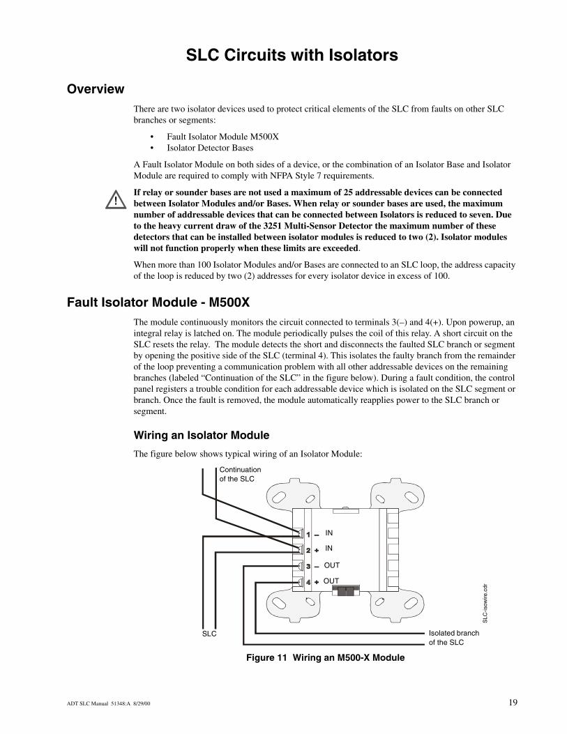
Fault Isolator Module - M500XThe module continuously monitors the circuit connected to terminals 3(–) and 4(+). Upon powerup, an integral relay is latched on. The module periodically pulses the coil of this relay. A short circuit on the SLC resets the relay. The module detects the short and disconnects the faulted SLC branch or segment by opening the positive side of the SLC (terminal 4). This isolates the faulty branch from the remainder of the loop preventing a communication problem with all other addressable devices on the remaining branches (labeled “Continuation of the SLC” in the figure below). During a fault condition, the control panel registers a trouble condition for each addressable device which is isolated on the SLC segment or branch. Once the fault is removed, the module automatically reapplies power to the SLC branch or segment.
Wiring an Isolator Module
The figure below shows typical wiring of an Isolator Module:
Figure 11 Wiring an M500-X Module
!
SLC Isolated branch of the SLC
SLC
-isow
ire.c
dr
Continuation of the SLC
OUT
OUT
IN
IN
ADT SLC Manual 51348:A 8/29/00 19
SLC Circuits with Isolators Isolator Detector Bases
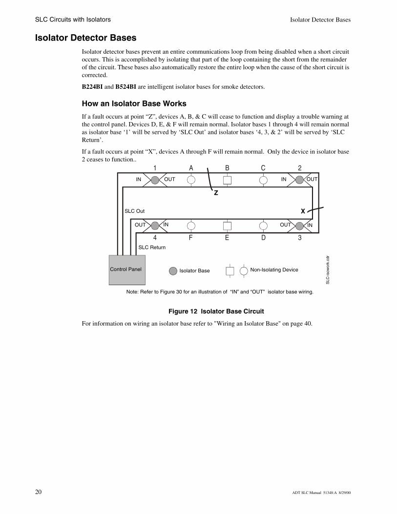
Isolator Detector BasesIsolator detector bases prevent an entire communications loop from being disabled when a short circuit occurs. This is accomplished by isolating that part of the loop containing the short from the remainder of the circuit. These bases also automatically restore the entire loop when the cause of the short circuit is corrected.
B224BI and B524BI are intelligent isolator bases for smoke detectors.
How an Isolator Base Works
If a fault occurs at point “Z”, devices A, B, & C will cease to function and display a trouble warning at the control panel. Devices D, E, & F will remain normal. Isolator bases 1 through 4 will remain normal as isolator base ‘1’ will be served by ‘SLC Out’ and isolator bases ‘4, 3, & 2’ will be served by ‘SLC Return’.
If a fault occurs at point “X”, devices A through F will remain normal. Only the device in isolator base 2 ceases to function..
Figure 12 Isolator Base Circuit
For information on wiring an isolator base refer to "Wiring an Isolator Base" on page 40.
1 2
4 3
A B C
F E D
Non-Isolating DeviceIsolator Base
X
Z
Control Panel
SLC Return
SLC Out
SLC
-isow
ork.
cdr
IN OUT IN OUT
INOUT INOUT
Note: Refer to Figure 30 for an illustration of “IN” and “OUT” isolator base wiring.
20 ADT SLC Manual 51348:A 8/29/00
NFPA Style 4 SLC Using an M500X Module SLC Circuits with Isolators
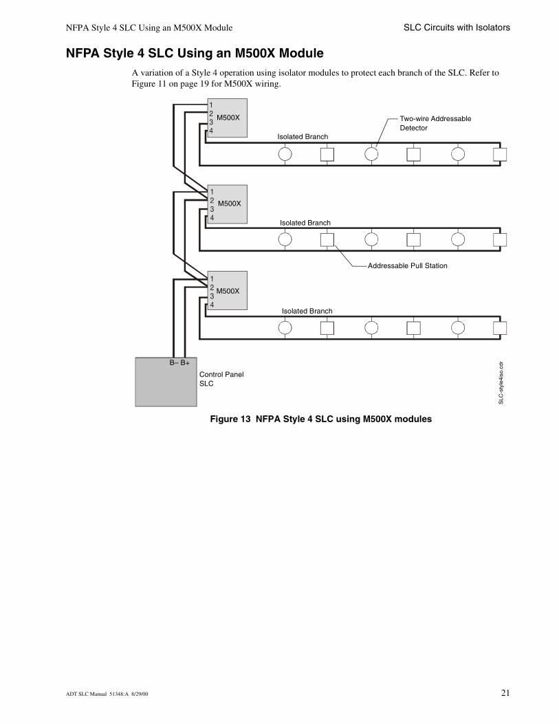
NFPA Style 4 SLC Using an M500X ModuleA variation of a Style 4 operation using isolator modules to protect each branch of the SLC. Refer to Figure 11 on page 19 for M500X wiring.
Figure 13 NFPA Style 4 SLC using M500X modules
1234
1234
1234
Two-wire Addressable Detector
Addressable Pull Station
SLC
-sty
le4i
so.c
dr
Control PanelSLC
Isolated Branch
B– B+
Isolated Branch
Isolated Branch
M500X
M500X
M500X
ADT SLC Manual 51348:A 8/29/00 21
SLC Circuits with Isolators NFPA Style 6 SLC Using M500X Modules
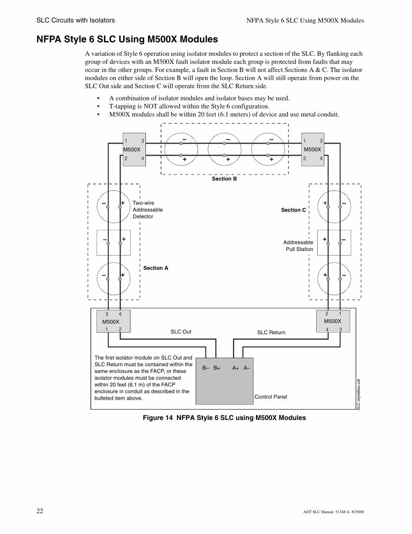
NFPA Style 6 SLC Using M500X ModulesA variation of Style 6 operation using isolator modules to protect a section of the SLC. By flanking each group of devices with an M500X fault isolator module each group is protected from faults that may occur in the other groups. For example, a fault in Section B will not affect Sections A & C. The isolator modules on either side of Section B will open the loop. Section A will still operate from power on the SLC Out side and Section C will operate from the SLC Return side.
• A combination of isolator modules and isolator bases may be used.• T-tapping is NOT allowed within the Style 6 configuration.• M500X modules shall be within 20 feet (6.1 meters) of device and use metal conduit.
Figure 14 NFPA Style 6 SLC using M500X Modules
1
2
3
4
1
2
3
4
2 1
4 3
3 4
1 2 SLC Out SLC Return
SLC
-sty
le6i
so.c
dr
Control Panel
B– B+ A+ A–
Two-wire Addressable Detector
AddressablePull Station
Section B
Section C
Section A
M500X M500X
M500X M500X
The first isolator module on SLC Out and SLC Return must be contained within the same enclosure as the FACP, or these isolator modules must be connected within 20 feet (6.1 m) of the FACP enclosure in conduit as described in the bulleted item above.
22 ADT SLC Manual 51348:A 8/29/00
NFPA Style 7 SLC Using Isolating Devices SLC Circuits with Isolators
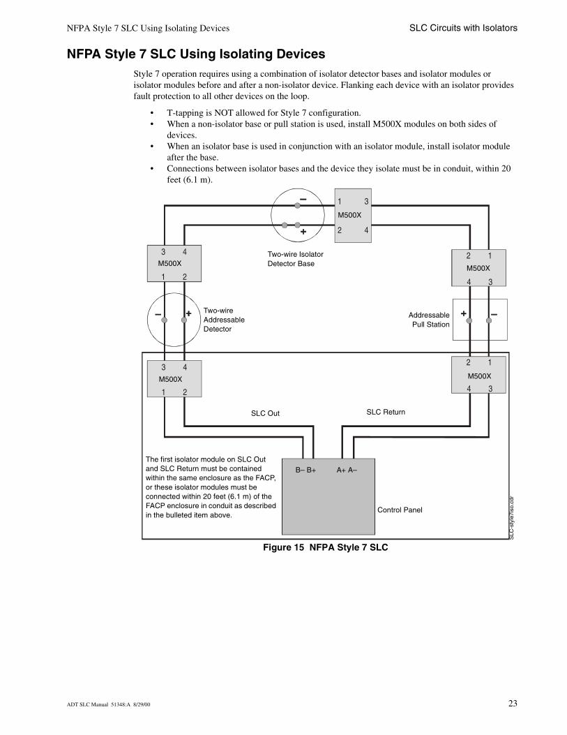
NFPA Style 7 SLC Using Isolating DevicesStyle 7 operation requires using a combination of isolator detector bases and isolator modules or isolator modules before and after a non-isolator device. Flanking each device with an isolator provides fault protection to all other devices on the loop.
• T-tapping is NOT allowed for Style 7 configuration.• When a non-isolator base or pull station is used, install M500X modules on both sides of
devices.• When an isolator base is used in conjunction with an isolator module, install isolator module
after the base.• Connections between isolator bases and the device they isolate must be in conduit, within 20
feet (6.1 m).
Figure 15 NFPA Style 7 SLC
1
2
3
4
2 1
4 3
2 1
4 3
3 4
1 2
3 4
1 2
SLC
-sty
le7i
so.c
dr
SLC Out SLC Return
Two-wire Addressable Detector
Two-wire Isolator Detector Base
AddressablePull Station
Control Panel
B– B+ A+ A–
M500X
M500X
M500X
M500X
M500X
The first isolator module on SLC Out and SLC Return must be contained within the same enclosure as the FACP, or these isolator modules must be connected within 20 feet (6.1 m) of the FACP enclosure in conduit as described in the bulleted item above.
ADT SLC Manual 51348:A 8/29/00 23

SLC Circuits with Isolators NFPA Style 7 SLC Using Isolating Devices
Notes
24 ADT SLC Manual 51348:A 8/29/00
Monitor Modules
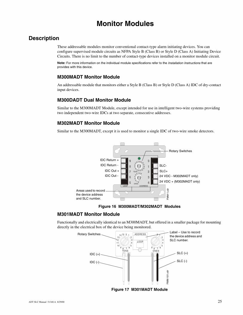
DescriptionThese addressable modules monitor conventional contact-type alarm initiating devices. You can configure supervised module circuits as NFPA Style B (Class B) or Style D (Class A) Initiating Device Circuits. There is no limit to the number of contact-type devices installed on a monitor module circuit.
Note: For more information on the individual module specifications refer to the Installation Instructions that are provides with this device.
M300MADT Monitor Module
An addressable module that monitors either a Style B (Class B) or Style D (Class A) IDC of dry-contact input devices.
M300DADT Dual Monitor Module
Similar to the M300MADT Module, except intended for use in intelligent two-wire systems providing two independent two-wire IDCs at two separate, consecutive addresses.
M302MADT Monitor Module
Similar to the M300MADT, except it is used to monitor a single IDC of two-wire smoke detectors.
Figure 16 M300MADT/M302MADT Modules
M301MADT Monitor Module
Functionally and electrically identical to an M300MADT, but offered in a smaller package for mounting directly in the electrical box of the device being monitored.
Figure 17 M301MADT Module
8 9101112
13141501
2345
6 7
8 9
012
345
6 7T E NS
O NE SLOO PLOO P A DD RES SA DD RES S
8
9
7
6
5
9
8
7
6
5
0
1
2
3
44
3
2
1
0
T E NS
O NE S
8 9
012
345
6 7
8 9 101112
13141501
2345
6 7
FM
M-1
.cdr
Rotary Switches
Areas used to record the device address and SLC number.
IDC Return +
IDC Return -
IDC Out +
IDC Out -
24 VDC + (M302MADT only)
24 VDC - M302MADT only)
SLC+
SLC-
0
10111213
14 15 ADD RE SS
LOO P
1234
TE NS O NES
67895
0 1234
67895
FM
M-1
01.c
dr
Label – Use to record the device address and SLC number.
Rotary Switches
IDC (+)
IDC (-)
SLC (+)
SLC (-)
ADT SLC Manual 51348:A 8/29/00 25
Monitor Modules Installation
InstallationWhen installing any of the modules, note the following:
3. The Initiating Device Circuit (IDC) is supervised and current-limited to 210 microamps @ 24 VDC (nominal).
4. The IDC provides the following services (do not mix):• Fire alarm service• Automatic and manual waterflow alarm service with normally open contact devices• Sprinkler supervisory service with normally open contact devices• Security service
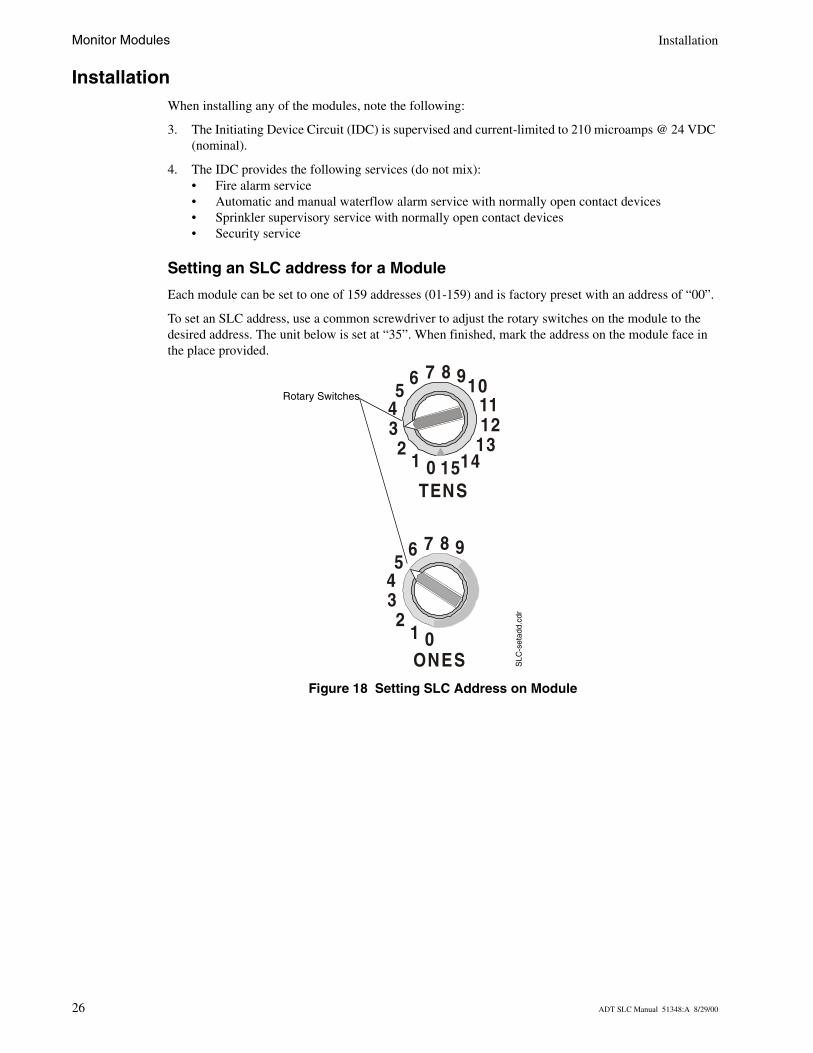
Setting an SLC address for a Module
Each module can be set to one of 159 addresses (01-159) and is factory preset with an address of “00”.
To set an SLC address, use a common screwdriver to adjust the rotary switches on the module to the desired address. The unit below is set at “35”. When finished, mark the address on the module face in the place provided.
Figure 18 Setting SLC Address on Module
TENS
ONES
8 9101112
13141501
2345
6 7
8 9
012
345
6 7
SLC
-set
add.
cdr
Rotary Switches
26 ADT SLC Manual 51348:A 8/29/00
M300MADT Wiring Diagrams Monitor Modules
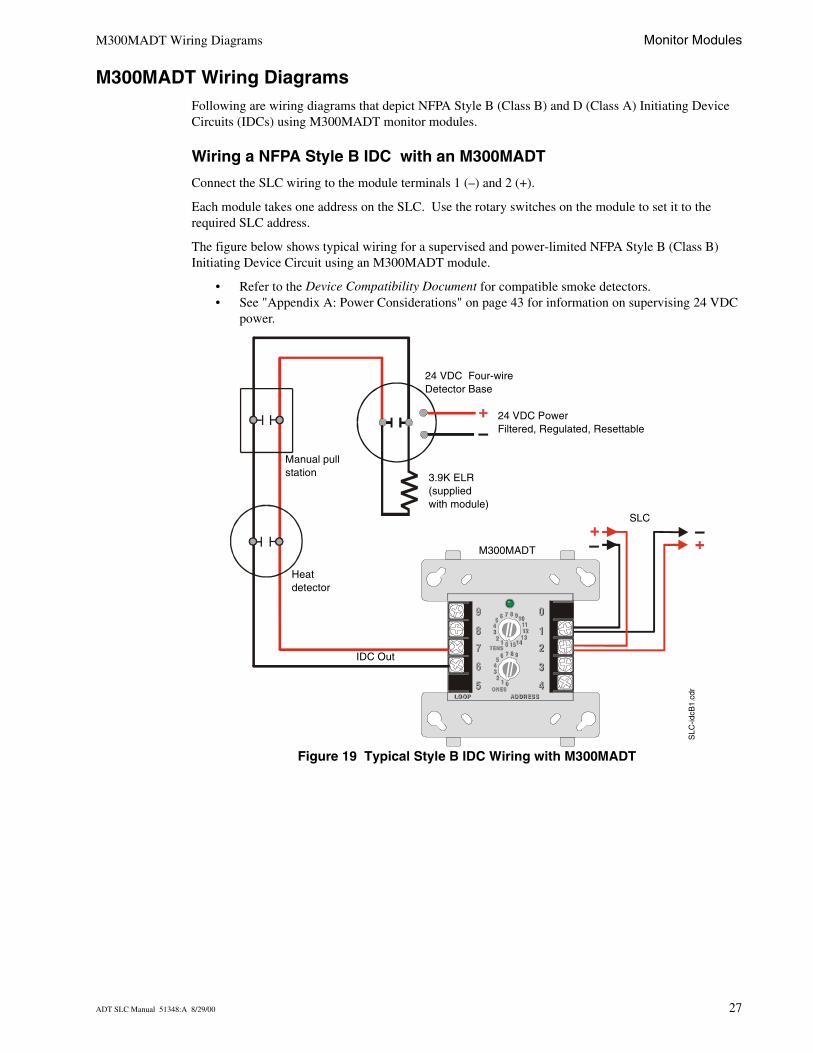
M300MADT Wiring DiagramsFollowing are wiring diagrams that depict NFPA Style B (Class B) and D (Class A) Initiating Device Circuits (IDCs) using M300MADT monitor modules.
Wiring a NFPA Style B IDC with an M300MADT
Connect the SLC wiring to the module terminals 1 (–) and 2 (+).
Each module takes one address on the SLC. Use the rotary switches on the module to set it to the required SLC address.
The figure below shows typical wiring for a supervised and power-limited NFPA Style B (Class B) Initiating Device Circuit using an M300MADT module.
• Refer to the Device Compatibility Document for compatible smoke detectors.• See "Appendix A: Power Considerations" on page 43 for information on supervising 24 VDC
power.
Figure 19 Typical Style B IDC Wiring with M300MADT
8 9101112
13141501
2345
6 7
8 9
012
345
6 7TENS
ONESLO OPLO OP AD DR ES SAD DR ES S
8
9
7
6
5
9
8
7
6
5
0
1
2
3
44
3
2
1
0
TENS
ONES
8 9
012
345
6 7
8 910111213
1415012
345
6 7
SLC
-idcB
1.cd
r
3.9K ELR(supplied with module)
Heat detector
SLC
M300MADT
IDC Out
24 VDC PowerFiltered, Regulated, Resettable
24 VDC Four-wire Detector Base
Manual pull station
ADT SLC Manual 51348:A 8/29/00 27
Monitor Modules M300MADT Wiring Diagrams
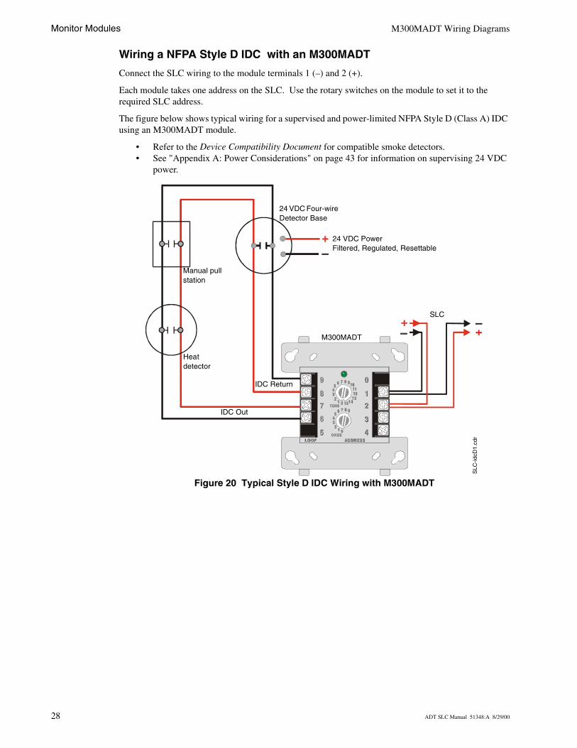
Wiring a NFPA Style D IDC with an M300MADT
Connect the SLC wiring to the module terminals 1 (–) and 2 (+).
Each module takes one address on the SLC. Use the rotary switches on the module to set it to the required SLC address.
The figure below shows typical wiring for a supervised and power-limited NFPA Style D (Class A) IDC using an M300MADT module.
• Refer to the Device Compatibility Document for compatible smoke detectors.• See "Appendix A: Power Considerations" on page 43 for information on supervising 24 VDC
power.
Figure 20 Typical Style D IDC Wiring with M300MADT
8 9101112
13141501
2345
6 7
8 9
012
345
6 7TENS
ONESLO OPLO OP AD DR ES SAD DR ES S
8
9
7
6
5
9
8
7
6
5
0
1
2
3
44
3
2
1
0
TENS
ONES
8 9
012
345
6 7
8 910111213
1415012
345
6 7
SLC
-idcD
1.cd
r
24 VDC Four-wire Detector Base
Manual pull station
Heat detector
SLC
M300MADT
IDC Out
24 VDC PowerFiltered, Regulated, Resettable
IDC Return
28 ADT SLC Manual 51348:A 8/29/00
M300DADT Wiring Diagrams Monitor Modules
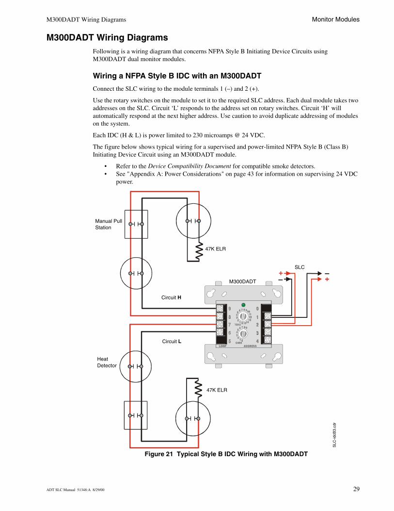
M300DADT Wiring DiagramsFollowing is a wiring diagram that concerns NFPA Style B Initiating Device Circuits using M300DADT dual monitor modules.
Wiring a NFPA Style B IDC with an M300DADT
Connect the SLC wiring to the module terminals 1 (–) and 2 (+).
Use the rotary switches on the module to set it to the required SLC address. Each dual module takes two addresses on the SLC. Circuit ‘L’ responds to the address set on rotary switches. Circuit ‘H’ will automatically respond at the next higher address. Use caution to avoid duplicate addressing of modules on the system.
Each IDC (H & L) is power limited to 230 microamps @ 24 VDC.
The figure below shows typical wiring for a supervised and power-limited NFPA Style B (Class B) Initiating Device Circuit using an M300DADT module.
• Refer to the Device Compatibility Document for compatible smoke detectors.• See "Appendix A: Power Considerations" on page 43 for information on supervising 24 VDC
power.
Figure 21 Typical Style B IDC Wiring with M300DADT
8 9101112
13141501
2345
6 7
8 9
012
345
6 7TENS
ONESLO OPLO OP AD DR ES SAD DR ES S
8
9
7
6
5
9
8
7
6
5
0
1
2
3
44
3
2
1
0
TENS
ONES
8 9
012
345
6 7
8 910111213
1415012
345
6 7
SLC
-idcB
3.cd
r
Heat Detector
Manual Pull Station
47K ELR
SLC
M300DADT
Circuit H
Circuit L
47K ELR
ADT SLC Manual 51348:A 8/29/00 29
Monitor Modules M302MADT Wiring Diagrams
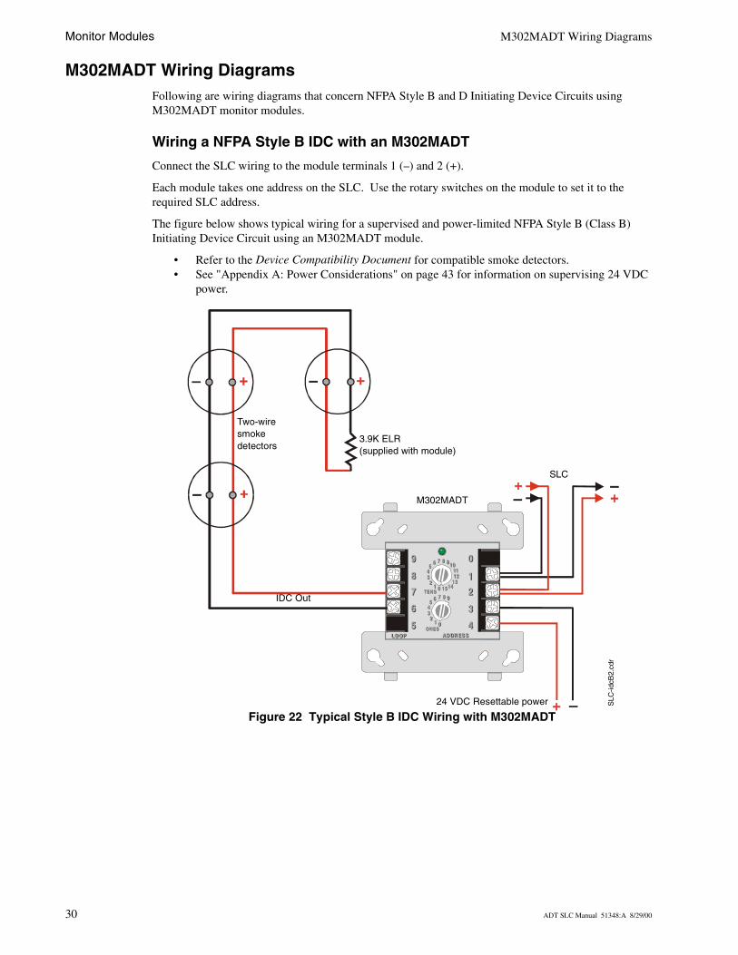
M302MADT Wiring DiagramsFollowing are wiring diagrams that concern NFPA Style B and D Initiating Device Circuits usingM302MADT monitor modules.
Wiring a NFPA Style B IDC with an M302MADT
Connect the SLC wiring to the module terminals 1 (–) and 2 (+).
Each module takes one address on the SLC. Use the rotary switches on the module to set it to the required SLC address.
The figure below shows typical wiring for a supervised and power-limited NFPA Style B (Class B) Initiating Device Circuit using an M302MADT module.
• Refer to the Device Compatibility Document for compatible smoke detectors.• See "Appendix A: Power Considerations" on page 43 for information on supervising 24 VDC
power.
Figure 22 Typical Style B IDC Wiring with M302MADT
8 9101112
13141501
2345
6 7
8 9
012
345
6 7TENS
ONESLO OPLO OP AD DR ES SAD DR ES S
8
9
7
6
5
9
8
7
6
5
0
1
2
3
44
3
2
1
0
TENS
ONES
8 9
012
345
6 7
8 9101112
13141501
2345
6 7
SLC
IDC Out
24 VDC Resettable power SLC
-idcB
2.cd
r
M302MADT
Two-wire smoke detectors
3.9K ELR(supplied with module)
30 ADT SLC Manual 51348:A 8/29/00
M302MADT Wiring Diagrams Monitor Modules
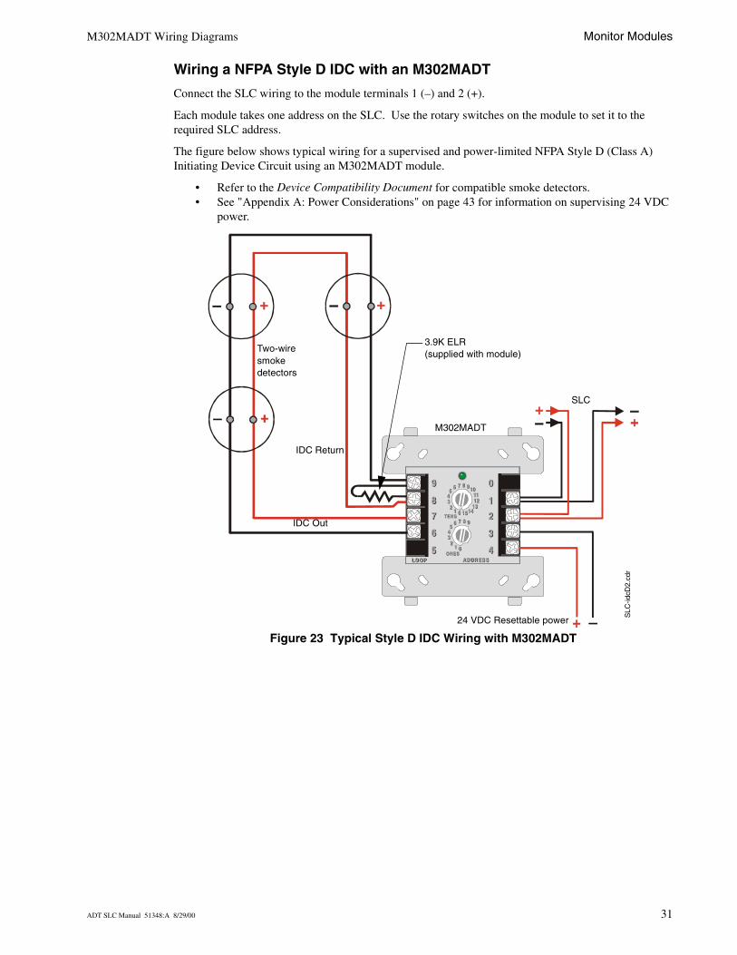
Wiring a NFPA Style D IDC with an M302MADT
Connect the SLC wiring to the module terminals 1 (–) and 2 (+).
Each module takes one address on the SLC. Use the rotary switches on the module to set it to the required SLC address.
The figure below shows typical wiring for a supervised and power-limited NFPA Style D (Class A) Initiating Device Circuit using an M302MADT module.
• Refer to the Device Compatibility Document for compatible smoke detectors.• See "Appendix A: Power Considerations" on page 43 for information on supervising 24 VDC
power.
Figure 23 Typical Style D IDC Wiring with M302MADT
8 9101112
13141501
2345
6 7
8 9
012
345
6 7TENS
ONESLO OPLO OP AD DR ES SAD DR ES S
8
9
7
6
5
9
8
7
6
5
0
1
2
3
44
3
2
1
0
TENS
ONES
8 9
012
345
6 7
8 9101112
13141501
2345
6 7
SLC
Two-wire smoke detectors
3.9K ELR(supplied with module)
IDC Out
M302MADT
24 VDC Resettable powerS
LC-id
cD2.
cdr
IDC Return
ADT SLC Manual 51348:A 8/29/00 31

Monitor Modules M302MADT Wiring Diagrams
Notes
32 ADT SLC Manual 51348:A 8/29/00
Control Modules
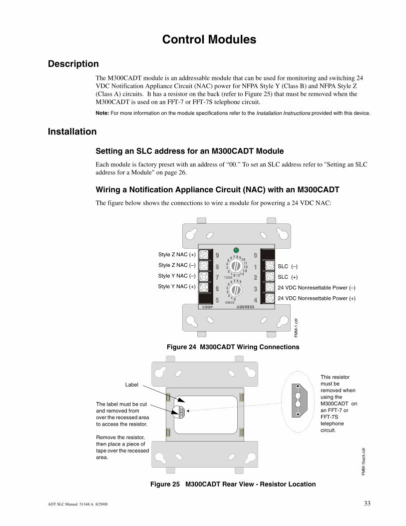
DescriptionThe M300CADT module is an addressable module that can be used for monitoring and switching 24 VDC Notification Appliance Circuit (NAC) power for NFPA Style Y (Class B) and NFPA Style Z (Class A) circuits. It has a resistor on the back (refer to Figure 25) that must be removed when the M300CADT is used on an FFT-7 or FFT-7S telephone circuit.
Note: For more information on the module specifications refer to the Installation Instructions provided with this device.
Installation
Setting an SLC address for an M300CADT Module
Each module is factory preset with an address of “00.” To set an SLC address refer to "Setting an SLC address for a Module" on page 26.
Wiring a Notification Appliance Circuit (NAC) with an M300CADT
The figure below shows the connections to wire a module for powering a 24 VDC NAC:
Figure 24 M300CADT Wiring Connections
Figure 25 M300CADT Rear View - Resistor Location
8 9101112
13141501
2345
6 7
8 9
012
345
6 7T ENS
O NESLO O PLO O P A DD RESSA DD RESS
8
9
7
6
5
9
8
7
6
5
0
1
2
3
44
3
2
1
0
T ENS
O NES
8 9
012
345
6 7
8 9 101112
13141501
2345
6 7
SLC (–)
SLC (+)
24 VDC Nonresettable Power (–)
24 VDC Nonresettable Power (+)
Style Z NAC (+)
Style Z NAC (–)
Style Y NAC (–)
Style Y NAC (+)
FM
M-1
.cdr
FM
M-1
back
.cdr
Label
The label must be cut and removed from over the recessed area to access the resistor.
Remove the resistor, then place a piece of tape over the recessed area.
This resistor must be removed when using the M300CADT on an FFT-7 or FFT-7S telephone circuit.
ADT SLC Manual 51348:A 8/29/00 33
Control Modules Wiring an M300CADT Module
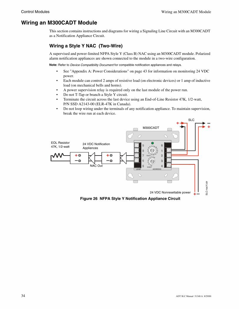
Wiring an M300CADT ModuleThis section contains instructions and diagrams for wiring a Signaling Line Circuit with an M300CADT as a Notification Appliance Circuit.
Wiring a Style Y NAC (Two-Wire)
A supervised and power-limited NFPA Style Y (Class B) NAC using an M300CADT module. Polarized alarm notification appliances are shown connected to the module in a two-wire configuration.
Note: Refer to Device Compatibility Document for compatible notification appliances and relays.
• See "Appendix A: Power Considerations" on page 43 for information on monitoring 24 VDC power.
• Each module can control 2 amps of resistive load (on electronic devices) or 1 amp of inductive load (on mechanical bells and horns).
• A power supervision relay is required only on the last module of the power run.• Do not T-Tap or branch a Style Y circuit. • Terminate the circuit across the last device using an End-of-Line Resistor 47K, 1/2-watt,
P/N SSD A2143-00 (ELR-47K in Canada).• Do not loop wiring under the terminals of any notification appliance. To maintain supervision,
break the wire run at each device.
Figure 26 NFPA Style Y Notification Appliance Circuit
8 9101112
13141501
2345
6 7
8 9
012
345
6 7TEN S
ONESLO OPLO OP AD DR ES SAD DR ES S
8
9
7
6
5
9
8
7
6
5
0
1
2
3
44
3
2
1
0
TEN S
ONES
8 9
012
345
6 7
8 910111213
1415012
345
6 7
EOL Resistor 47K, 1/2-watt
24 VDC Notification Appliances
M300CADT
SLC
NAC Out
24 VDC Nonresettable power
SLC
-nac
Y.cd
r
34 ADT SLC Manual 51348:A 8/29/00
Wiring an M300CADT Module Control Modules
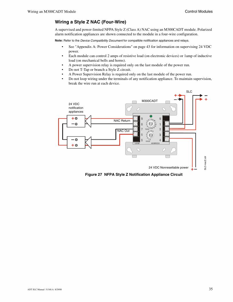
Wiring a Style Z NAC (Four-Wire)
A supervised and power-limited NFPA Style Z (Class A) NAC using an M300CADT module. Polarized alarm notification appliances are shown connected to the module in a four-wire configuration.
Note: Refer to the Device Compatibility Document for compatible notification appliances and relays.
• See "Appendix A: Power Considerations" on page 43 for information on supervising 24 VDC power.
• Each module can control 2 amps of resistive load (on electronic devices) or 1amp of inductive load (on mechanical bells and horns).
• A power supervision relay is required only on the last module of the power run.• Do not T-Tap or branch a Style Z circuit. • A Power Supervision Relay is required only on the last module of the power run.• Do not loop wiring under the terminals of any notification appliance. To maintain supervision,
break the wire run at each device.
Figure 27 NFPA Style Z Notification Appliance Circuit
8 9 101112
13141501
2345
6 7
8 9
012
345
6 7TEN S
ON ESLO OPLO OP AD DR ES SAD DR ES S
8
9
7
6
5
9
8
7
6
5
0
1
2
3
44
3
2
1
0
TEN S
ON ES
8 9
012
345
6 7
8 9 101112
13141501
2345
6 7
24 VDC notification appliances
M300CADT
NAC Out
24 VDC Nonresettable power
SLC
SLC
-nac
Z.c
dr
NAC Return
ADT SLC Manual 51348:A 8/29/00 35

Control Modules Wiring an M300CADT Module
Notes
36 ADT SLC Manual 51348:A 8/29/00
Relay Module
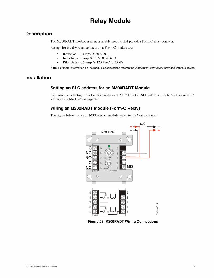
DescriptionThe M300RADT module is an addressable module that provides Form-C relay contacts.
Ratings for the dry relay contacts on a Form-C module are:
• Resistive - 2 amps @ 30 VDC• Inductive - 1 amp @ 30 VDC (0.6pf)• Pilot Duty - 0.5 amp @ 125 VAC (0.35pF)
Note: For more information on the module specifications refer to the Installation Instructions provided with this device.
Installation
Setting an SLC address for an M300RADT Module
Each module is factory preset with an address of “00.” To set an SLC address refer to “Setting an SLC address for a Module” on page 24.
Wiring an M300RADT Module (Form-C Relay)
The figure below shows an M300RADT module wired to the Control Panel:
Figure 28 M300RADT Wiring Connections
8 9101112
13141501
2345
6 7
8 9
012
345
6 7TENS
ONESLO OPLO OP AD DR ES SAD DR ES S
8
9
7
6
5
9
8
7
6
5
0
1
2
3
44
3
2
1
0
TENS
ONES
8 9
012
345
6 7
8 9101112
13141501
2345
6 7
8
9
7
6
5
9
8
7
6
5
0
1
2
3
44
3
2
1
0
LO OPLO OP
SLC
SLC
-frm
C.c
dr
M300RADT
NO
CNCNO
CNC
ADT SLC Manual 51348:A 8/29/00 37

Relay Module Installation
Notes
38 ADT SLC Manual 51348:A 8/29/00
Intelligent Detector Bases
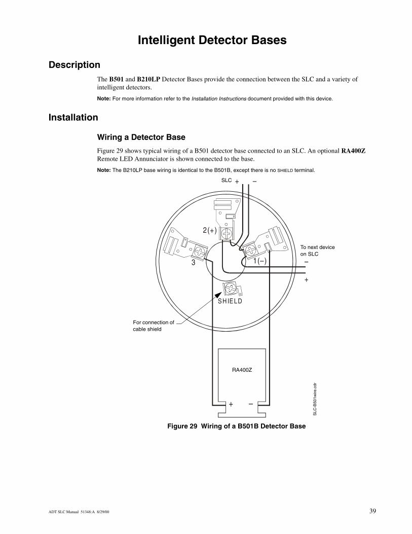
DescriptionThe B501 and B210LP Detector Bases provide the connection between the SLC and a variety of intelligent detectors.
Note: For more information refer to the Installation Instructions document provided with this device.
Installation
Wiring a Detector Base
Figure 29 shows typical wiring of a B501 detector base connected to an SLC. An optional RA400Z Remote LED Annunciator is shown connected to the base.
Note: The B210LP base wiring is identical to the B501B, except there is no SHIELD terminal.
Figure 29 Wiring of a B501B Detector Base
1(–)
2(+)
+ –
–
+
3
SH IELD
+ –
To next device on SLC
SLC
SLC
-B50
1wire
.cdr
RA400Z
For connection of cable shield
ADT SLC Manual 51348:A 8/29/00 39
Intelligent Detector Bases Installation
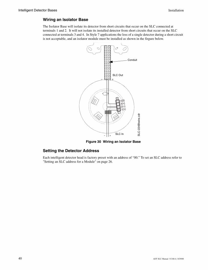
Wiring an Isolator Base
The Isolator Base will isolate its detector from short circuits that occur on the SLC connected at terminals 1 and 2. It will not isolate its installed detector from short circuits that occur on the SLC connected at terminals 3 and 4. In Style 7 applications the loss of a single detector during a short circuit is not acceptable, and an isolator module must be installed as shown in the firgure below.
Figure 30 Wiring an Isolator Base
Setting the Detector Address
Each intelligent detector head is factory preset with an address of “00.” To set an SLC address refer to "Setting an SLC address for a Module" on page 26.
– +
– + SLC In
SLC Out
SLC
-224
BIw
ire.c
dr
Conduit
40 ADT SLC Manual 51348:A 8/29/00
Addressable Manual Pull Station
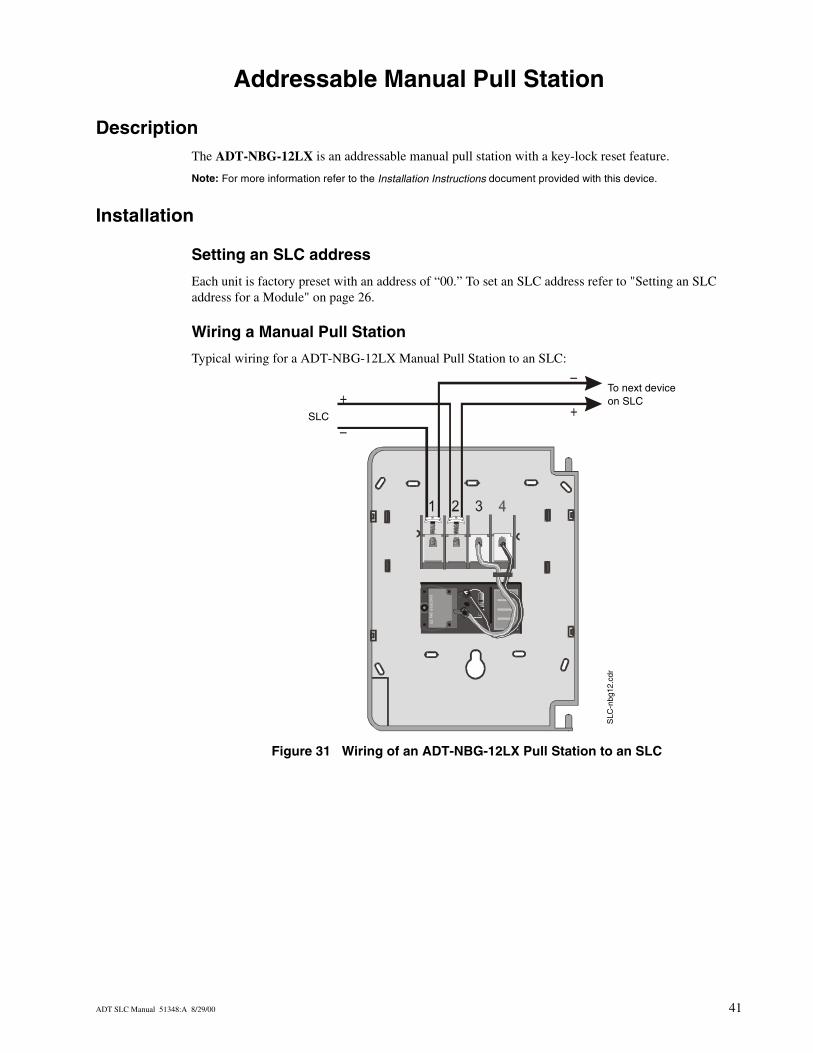
DescriptionThe ADT-NBG-12LX is an addressable manual pull station with a key-lock reset feature.
Note: For more information refer to the Installation Instructions document provided with this device.
Installation
Setting an SLC address
Each unit is factory preset with an address of “00.” To set an SLC address refer to "Setting an SLC address for a Module" on page 26.
Wiring a Manual Pull Station
Typical wiring for a ADT-NBG-12LX Manual Pull Station to an SLC:
Figure 31 Wiring of an ADT-NBG-12LX Pull Station to an SLC
+
–
–
+US
PAT
444
0991
SLC
To next device on SLC
SLC
-nbg
12.c
dr
ADT SLC Manual 51348:A 8/29/00 41

Addressable Manual Pull Station Installation
Notes
42 ADT SLC Manual 51348:A 8/29/00
Appendix A: Power Considerations
Supplying Power to 24 VDC Detectors
Resistance and Size
To determine the minimum resistance that can be tolerated in supplying power to 24 VDC 4-wire detectors, use the calculation below. Use this resistance to select the proper gauge wire for the power run from the manufacturers specifications for the desired wire.
Where:
Rmax = maximum resistance of the 24 VDC wiresVms = minimum supply voltage (see Table 3 below)Vom = minimum operating voltage of the detector or end-of-line relay, whichever is greater, in voltsN = total number of detectors on the 24 VDC supply circuitIs = detector current in standbyNa = number of detectors on the 24 VDC power circuit which must function at the same time in alarmIa = detector current in alarmIr = end-of-line relay current
The minimum supply voltages produced by ADT power supplies are listed below:
Table 3 Minimum Supply Voltage
Power Supply Vms
FCPS-24 19.1
MPS-24A 19.6
MPS-24B 20.1
MPS-400 19.23
Rmax =(Vms - Vom)
(N)(Is) + (Na)(Ia) + (Ir)
ADT SLC Manual 51348:A 8/29/00 43
Appendix A: Power Considerations Supervising 24 VDC Power
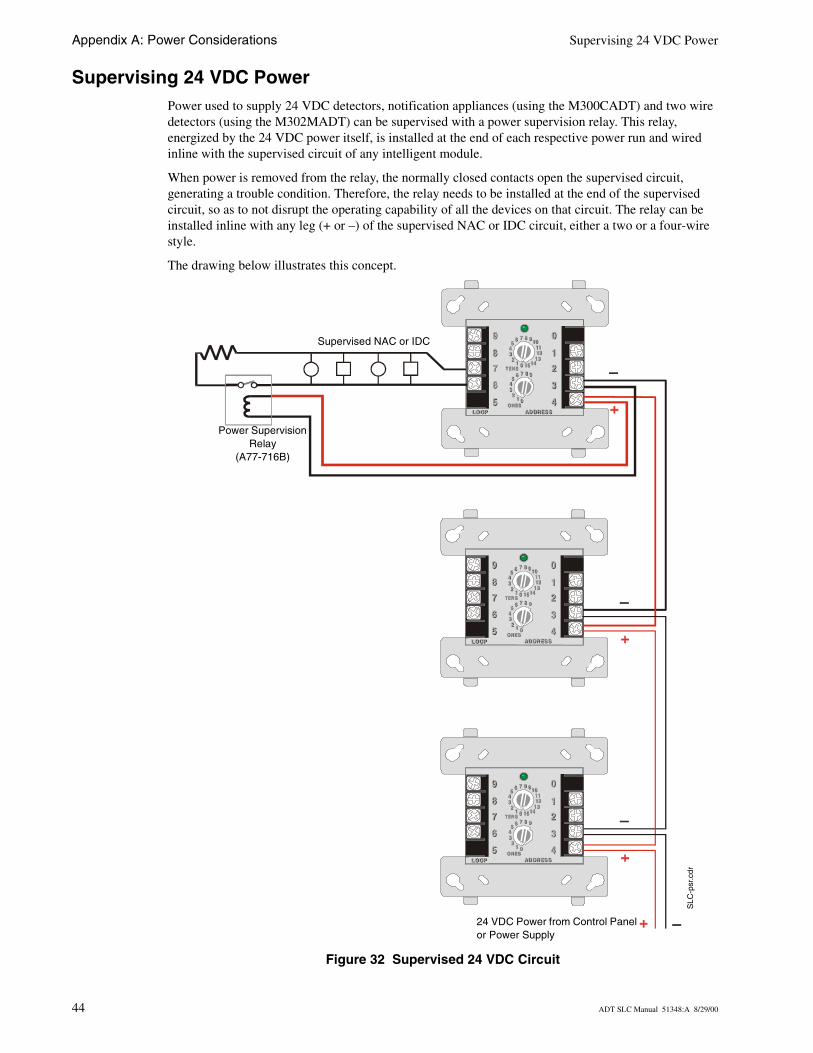
Supervising 24 VDC PowerPower used to supply 24 VDC detectors, notification appliances (using the M300CADT) and two wire detectors (using the M302MADT) can be supervised with a power supervision relay. This relay, energized by the 24 VDC power itself, is installed at the end of each respective power run and wired inline with the supervised circuit of any intelligent module.
When power is removed from the relay, the normally closed contacts open the supervised circuit, generating a trouble condition. Therefore, the relay needs to be installed at the end of the supervised circuit, so as to not disrupt the operating capability of all the devices on that circuit. The relay can be installed inline with any leg (+ or –) of the supervised NAC or IDC circuit, either a two or a four-wire style.
The drawing below illustrates this concept.
Figure 32 Supervised 24 VDC Circuit
8 9101112
13141501
2345
6 7
8 9
012
345
6 7TENS
ONESLOOPLOOP AD DRES SAD DRES S
8
9
7
6
5
9
8
7
6
5
0
1
2
3
44
3
2
1
0
TENS
ONES
8 9
012
345
6 7
8 910111213
1415012
345
6 7
8 9101112
13141501
2345
6 7
8 9
012
345
6 7TENS
ONESLOOPLOOP AD DRES SAD DRES S
8
9
7
6
5
9
8
7
6
5
0
1
2
3
44
3
2
1
0
TENS
ONES
8 9
012
345
6 7
8 9101112
13141501
2345
6 7
8 9101112
13141501
2345
6 7
8 9
012
345
6 7TENS
ONESLOOPLOOP AD DRES SAD DRES S
8
9
7
6
5
9
8
7
6
5
0
1
2
3
44
3
2
1
0
TENS
ONES
8 9
012
345
6 7
8 9101112
13141501
2345
6 7
SLC
-psr
.cdr
24 VDC Power from Control Panel or Power Supply
Power Supervision Relay
(A77-716B)
Supervised NAC or IDC
44 ADT SLC Manual 51348:A 8/29/00
Supervising 24 VDC Power to Notification Appliances Appendix A: Power Considerations
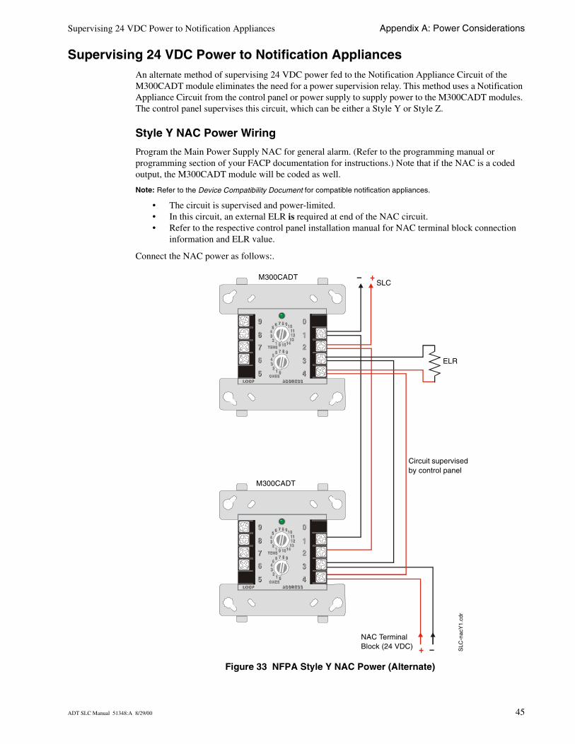
Supervising 24 VDC Power to Notification AppliancesAn alternate method of supervising 24 VDC power fed to the Notification Appliance Circuit of the M300CADT module eliminates the need for a power supervision relay. This method uses a Notification Appliance Circuit from the control panel or power supply to supply power to the M300CADT modules. The control panel supervises this circuit, which can be either a Style Y or Style Z.
Style Y NAC Power Wiring
Program the Main Power Supply NAC for general alarm. (Refer to the programming manual or programming section of your FACP documentation for instructions.) Note that if the NAC is a coded output, the M300CADT module will be coded as well.
Note: Refer to the Device Compatibility Document for compatible notification appliances.
• The circuit is supervised and power-limited.• In this circuit, an external ELR is required at end of the NAC circuit. • Refer to the respective control panel installation manual for NAC terminal block connection
information and ELR value.
Connect the NAC power as follows:.
Figure 33 NFPA Style Y NAC Power (Alternate)
8 9101112
13141501
2345
6 7
8 9
012
345
6 7TENS
ONESLO OPLO OP AD DR ES SAD DR ES S
8
9
7
6
5
9
8
7
6
5
0
1
2
3
44
3
2
1
0
TENS
ONES
8 9
012
345
6 7
8 9101112
13141501
2345
6 7
8 9101112
13141501
2345
6 7
8 9
012
345
6 7TENS
ONESLO OPLO OP AD DR ES SAD DR ES S
8
9
7
6
5
9
8
7
6
5
0
1
2
3
44
3
2
1
0
TENS
ONES
8 9
012
345
6 7
8 9101112
13141501
2345
6 7
– +
+ –
M300CADTSLC
SLC
-nac
Y1.
cdr
ELR
NAC Terminal Block (24 VDC)
Circuit supervised by control panel
M300CADT
ADT SLC Manual 51348:A 8/29/00 45
Appendix A: Power Considerations Supervising 24 VDC Power to Notification Appliances
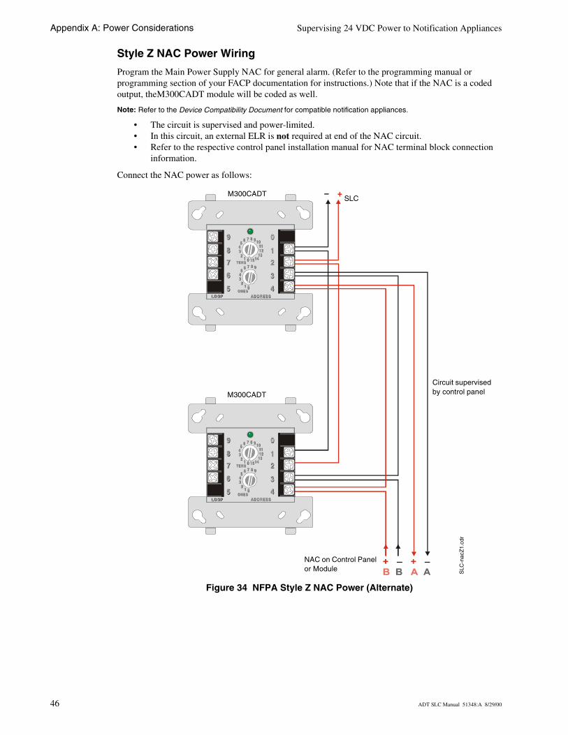
Style Z NAC Power Wiring
Program the Main Power Supply NAC for general alarm. (Refer to the programming manual or programming section of your FACP documentation for instructions.) Note that if the NAC is a coded output, theM300CADT module will be coded as well.
Note: Refer to the Device Compatibility Document for compatible notification appliances.
• The circuit is supervised and power-limited.• In this circuit, an external ELR is not required at end of the NAC circuit.• Refer to the respective control panel installation manual for NAC terminal block connection
information.
Connect the NAC power as follows:
Figure 34 NFPA Style Z NAC Power (Alternate)
8 9101112
13141501
2345
6 7
8 9
012
345
6 7TENS
ONESLO OPLO OP AD DR ES SAD DR ES S
8
9
7
6
5
9
8
7
6
5
0
1
2
3
44
3
2
1
0
TENS
ONES
8 9
012
345
6 7
8 9101112
13141501
2345
6 7
8 9101112
13141501
2345
6 7
8 9
012
345
6 7TENS
ONESLO OPLO OP AD DR ES SAD DR ES S
8
9
7
6
5
9
8
7
6
5
0
1
2
3
44
3
2
1
0
TENS
ONES
8 9
012
345
6 7
8 9101112
13141501
2345
6 7
– +SLC
M300CADT
SLC
-nac
Z1.
cdr
NAC on Control Panel or Module
Circuit supervised by control panelM300CADT
46 ADT SLC Manual 51348:A 8/29/00
Appendix B: Surge Suppression
IntroductionThere is one primary and there are three secondary surge protectors approved for use with the FACP’s listed in this appendix
Primary Surge Protector:
• 326-2M TII Station Protector
Secondary Surge Protectors:
• DTK-2LVLP-F Diversified Technology Group, Inc. 1720 Starkey Rd. Largo, FL 33771 (727) 812-5000
• SLCP-030 EDCO 1805 N.E. 19th Ave. Ocala, FL 34470 (352) 732-3029• PLP-42N Northern Technologies, Inc. 23123 E. Madison Ave. Liberty Lake, WA 99019
(800) 727-9119
Note: For detailed information refer to the installation documentation supplied with the unit.
One primary surge protector must be used with each SLC wiring pair whenever SLC wiring runs outside the building.
• Install primary protection only as shown in this document.• Refer to NEC Article 800 and local building code requirements.
Additional primary surgesuppressors may be added as required by the NEC. Add these additional suppressors in series with the SLC wiring at the building entry/exit.
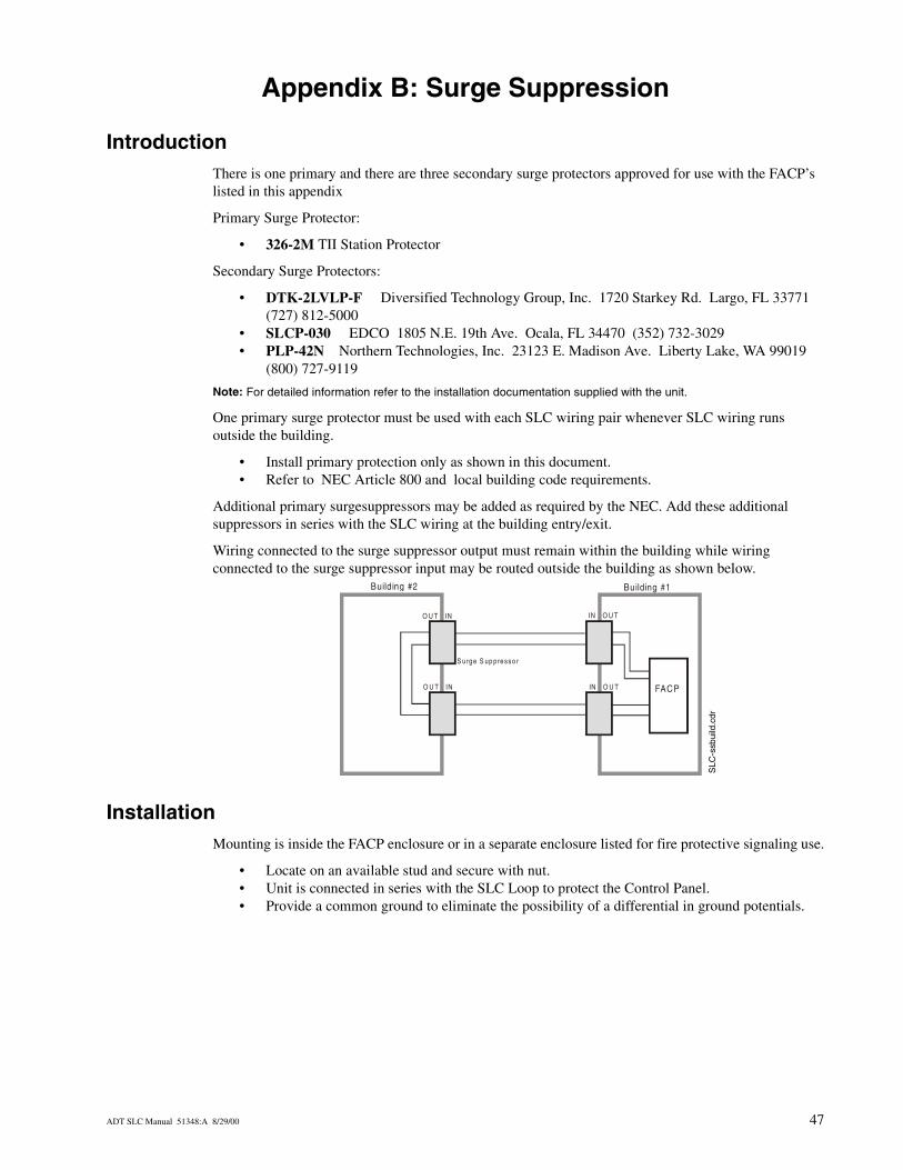
Wiring connected to the surge suppressor output must remain within the building while wiring connected to the surge suppressor input may be routed outside the building as shown below.
InstallationMounting is inside the FACP enclosure or in a separate enclosure listed for fire protective signaling use.
• Locate on an available stud and secure with nut.• Unit is connected in series with the SLC Loop to protect the Control Panel.• Provide a common ground to eliminate the possibility of a differential in ground potentials.
O U T IN
IN O U T
IN O U T
O U T IN FACP
S urge S up presso r
Building #2 Building #1
SLC
-ssb
uild
.cdr
ADT SLC Manual 51348:A 8/29/00 47
Appendix B: Surge Suppression Installation
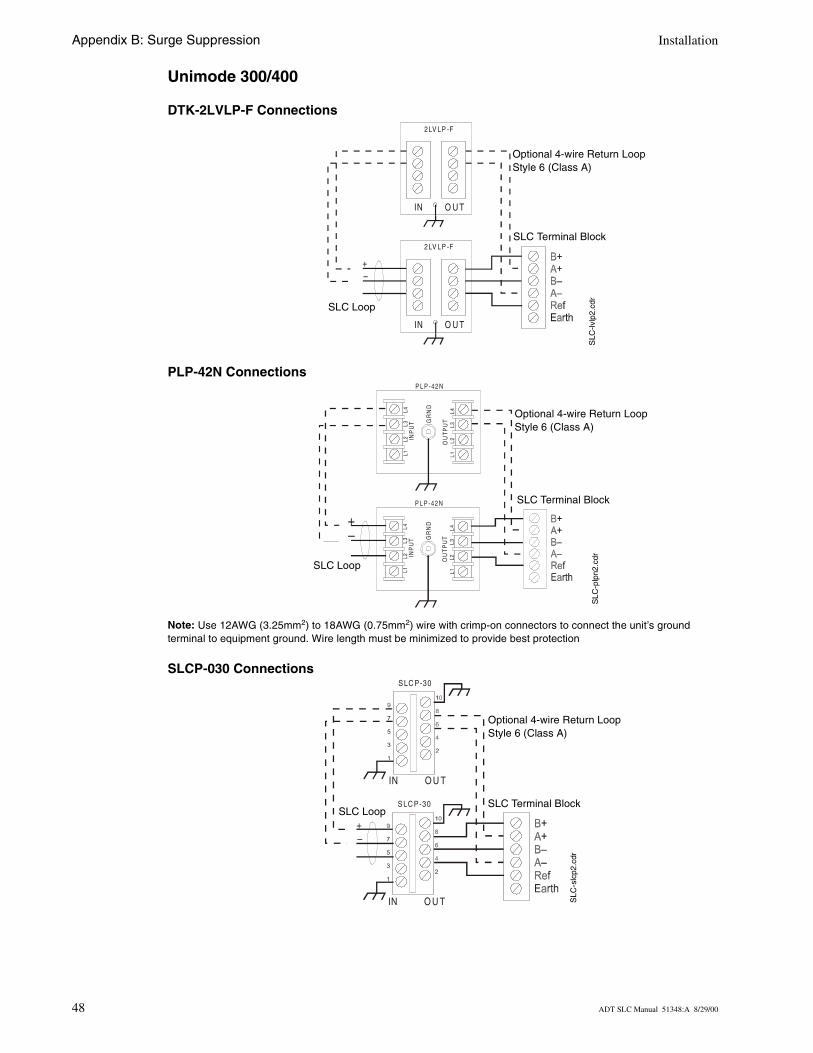
Unimode 300/400
DTK-2LVLP-F Connections
PLP-42N Connections
Note: Use 12AWG (3.25mm2) to 18AWG (0.75mm2) wire with crimp-on connectors to connect the unit’s ground terminal to equipment ground. Wire length must be minimized to provide best protection
SLCP-030 Connections
IN
IN
O U T
O U T
2LV LP -F
2LV LP -F
+–
SLC
-lvlp
2.cd
r
SLC Loop
SLC Terminal Block
Optional 4-wire Return LoopStyle 6 (Class A)
–+
INP
UT
OU
TP
UT
P L P -42 N
L1
L2
L
3
L4
L1
L2
L
3
L4
GR
ND
INP
UT
OU
TP
UT
P L P -42 N
L1
L2
L
3
L4
L1
L2
L
3
L4
GR
ND
SLC
-plp
n2.c
dr
SLC Loop
SLC Terminal Block
Optional 4-wire Return LoopStyle 6 (Class A)
IN
IN
O U T
O U T
S LC P-30
S LC P-30
+–
SLC
-slc
p2.c
dr
SLC Terminal BlockSLC Loop
Optional 4-wire Return LoopStyle 6 (Class A)
48 ADT SLC Manual 51348:A 8/29/00
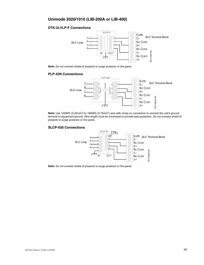
Unimode 2020/1010 (LIB-200A or LIB-400)
DTK-2LVLP-F Connections
Note: Do not connect shield (if present) to surge protector or fire panel.
PLP-42N Connections
Note: Use 12AWG (3.25mm2) to 18AWG (0.75mm2) wire with crimp-on connectors to connect the unit’s ground terminal to equipment ground. Wire length must be minimized to provide best protection. Do not connect shield (if present) to surge protector or fire panel.
SLCP-030 Connections
Note: Do not connect shield (if present) to surge protector or fire panel.
IN O U T
2 LV LP -F
–
–+
+
SLC
-lvlp
3.cd
r
SLC Terminal Block
SLC Loop
INP
UT
OU
TP
UT
P LP -42N
L1
L2
L
3
L4
L1
L2
L
3
L4
GR
ND
SLC
-plp
n3.c
dr
SLC Terminal Block
SLC Loop
IN O U T
S LC P -30
+
+
–
–
SLC Terminal Block
SLC Loop
SLC
-slc
p3.c
dr
ADT SLC Manual 51348:A 8/29/00 49

50
N3232
Aadad
ADAu
BB2B5bu
CcabcapCA
circircocoCo
DDCdede
de
dodrydryDTdu
EeleELEn
FFAfacfauFaFFFir
umerics51 Multi-Sensor Detector 196-2M TII Station Protector 47
dress capacity 19dressable
devices 19modules 9
T-NBG-12LX 41thority Having Jurisdiction 12
10LP detector base 3901 detector base 39ilding entry/exit 47
inet 15, 16acity of devices 12UTIONMaximum number of devices between isolators 19
cuit fault 9cuit, speaker/telephone 10ded output 45nnector screw 15ntrol Modules 9, 33
resistance 13, 14tector base, wiring diagram 39tectors
listing 10vices
addressable 19cument sources 11 relay contacts 37-contact output, relay modules 9K-2LVLP-F 47
plicate addressing 29
ctrical interference 13R, external 45, 46d-of-Line Resistor 34
CP 47tory preset address value 26, 40, 41lt 19, 20, 22
ult Isolator Module M500X 19T-7 or FFT-7S telephone circuit 33e Alarm Control Panels 9
Fire alarm service 26floating segments, shield 16Form-C relay contacts 37four-wire configuration 35
Ggeneral alarm 45
IInitiating Device Circuits 10, 25, 26, 27, 29Intelligent Detector Bases 39Isolator Base 10, 19, 20, 23Isolator Base, wiring of 40Isolator Module 9, 19, 22, 23
Jjunction box 16
Kkey-lock reset feature 41
LLED operation 12LIB-200A 13LIB-400 13local building code 47Loop Resistance 13, 14loops 14
MM300CADT 33, 35, 44, 45
resistor on the back 33M300CADT, Wiring Diagrams 34M300DADT 25, 29M300MADT 25, 27, 28M300RADT 37M300RADT, wiring diagram 37M301MADT 25M302MADT 25, 30, 44metal box 16metal conduit 15, 16, 22minimum resistance, to determine 43Minimum Supply Voltage 43module circuits, configuring 25modules
addressable 9control 9monitor 9relay 9
Monitor Modules 9, 25multiplex subsystem 10Multi-Sensor Detector-3251 19
The ADT SLC Wiring Manual PN 51348:A 8/29/00

NNAC 10NAC wiring 33, 45NEC Article 800 47NFPA Style 4
wiring of 17with M500X 21
NFPA Style 6wiring of 18with M500X 22
NFPA Style 7 19with isolator device 23
NFPA Style BIDC wiring 27, 29, 30
NFPA Style DIDC wiring 28, 31
NFPA Style Y 33wiring of 34
NFPA Style Z 33wiring of 35
PPLP-42N 47Power Considerations 43power supervision relay 34, 35, 44power-limited 45, 46primary surge protector 47Pull Stations 10, 23Pull Stations, wiring of 41
RRA400Z Remote LED Annunciator 39Radiated Emissions, reduction of 15Relay base 10, 19Relay Module 9remote switching center 10Resistor Location, M300CADT 33rotary switches 26, 29, 30, 31
Ssecondary surge protector 47Security service 26Shield drain wire 15shielded wire 16shielding not recommended 16short circuit 19, 20Signaling Line Circuit 9SLC address, setting of 26SLC Circuits with Isolators 19
max addressable devices 19SLC Circuits without Isolator 17SLC Performance 12SLC terminal block 15SLC wiring 27, 28, 30, 31SLCP-030 47
Sounder base 10, 19speaker circuit 10Sprinkler supervsion 26Standard Base 10Style Y NAC Power Wiring 45Style Z NAC Power Wiring 46supervised 45, 46Supervising 24 VDC Power 44Supervising 24 VDC Power to Notification Appliances 45supplying power 43Surge protector 12, 47Surge Suppression 47Surge suppressor wiring 47–49
Ttelephone circuit 10, 33termination of shield 15Transponders 10trouble condition 19T-tapping 13, 17, 18, 22, 23, 35twisted shielded pair wiring 13twisted-pair wire 16two-wire configuration 34
UUnimode 2020/1010 9Unimode 300/400 9Unimode II w/ AIM 9
WWaterflow alarm service, automatic and manual 26wire length 13, 14wire nuts 16Wire size 13wire, selecting proper gauge 43wiring
NACs 33Wiring Diagrams, M300MADT 27Wiring Diagrams, M302MADT 30wiring pair 47Wiring style requirements 12
XXP Series Transponders 10XP5-C Transponder 10XP5-M Transponder 10
The ADT SLC Wiring Manual PN 51348:A 8/29/00 51


![Circuit Switching - Signaling [Compatibility Mode]](https://img.pdfslide.net/doc/110x75/546b7050b4af9f892c8b4c91/circuit-switching-signaling-compatibility-mode.jpg)