Embed Size (px)
Citation preview
Peter Iddon Silverson V1-1.doc 1
Silverson L4RT High Shear Mixer
Safety
The points below must be observed to prevent serious injury to the operator or damage to the mixer:
• Always turn the speed regulator to zero, and switch the machine off, when not in use.• Always switch machine off when adding or removing attachments.• Never touch any moving parts.• Always operate mixer with mixing head assembly completely submerged in liquid, to prevent
overheating and seizure of the mixing assembly.• Before operation, ensure shaft coupling sleeve is secure and covers the coupling pin.• Always make sure that no obstructions are below the mixing head when lowering the mixer body.• Make sure liquid to be mixed is in a large enough container.• The mixer is not explosion or flame proof, so always use in a well ventilated area if flammable
solvents are present.• Users should be aware that extended high speed mixing could cause significant heating of
mixtures.• Mixing of volatile solvents or toxic ingredients should only be done in a fume cupboard.
Significant dusting of powders can occur.• Always start mixer at lowest speed, and then gradually increase speed until desired setting, to
prevent splashing.• Clean mixing head and assembly as soon as possible after use, to prevent corrosion.• The mixer is splash proof, but not waterproof. Never immerse unit in water or spray with hose.• Take care when changing mixing heads, as the rotor blades may be sharp.
Do not use the Silverson L4RT High Speed Mixer unless you have been trained in its use.These instructions are for guidance only. Please read all relevant hazard assessments.
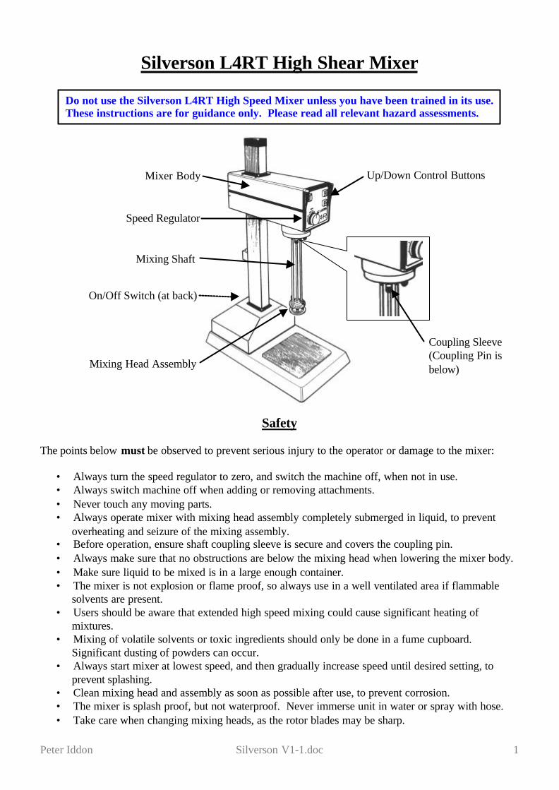
Up/Down Control Buttons
Mixing Head Assembly
On/Off Switch (at back)
Speed Regulator
Coupling Sleeve(Coupling Pin isbelow)
Mixing Shaft
Mixer Body
Peter Iddon Silverson V1-1.doc 2
General
The Silverson L4RT High Speed Mixer is used for mixing liquid/liquid or liquid/solid mixtures at speedsof up to 8000 rpm.
The mixer body is raised or lowered electrically. It will stop automatically at the higher and lower limitsof movement (although it will not automatically stop if it hits an obstruction between its upper and lowerlimits).
Several accessories are supplied with the mixer, which can be interchanged depending on what mixingconditions are required [see below].
Accessories
Cleaning and Changing Screens / Flow Head on Standard Mixing Assembly
General Purpose Disintegrating HeadSuitable for general mixing or disintegration of solids.
Square Hole High Shear ScreenHigh shear screen suitable for emulsion and fine colloid suspension preparation.
Emulsor ScreenLower shear screen suitable for liquid/liquid and emulsion preparations.
Axial Flow HeadUsed in addition to one of the above screens to force liquid flow upwardsThis can reduce aeration or help maintain large suspensions, but high mixing speedscan cause liquid to be ejected from the mixing vessel.
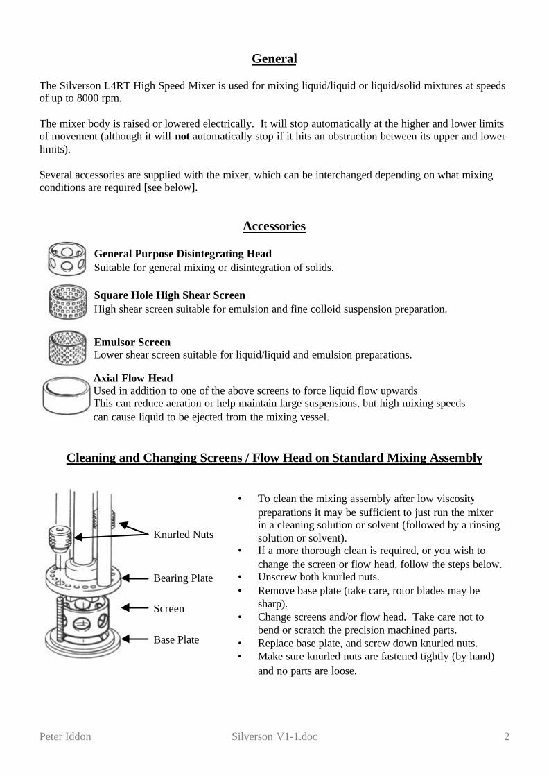
Knurled Nuts
Screen
Bearing Plate
Base Plate
• To clean the mixing assembly after low viscositypreparations it may be sufficient to just run the mixerin a cleaning solution or solvent (followed by a rinsingsolution or solvent).
• If a more thorough clean is required, or you wish tochange the screen or flow head, follow the steps below.
• Unscrew both knurled nuts.• Remove base plate (take care, rotor blades may be
sharp).• Change screens and/or flow head. Take care not to
bend or scratch the precision machined parts.• Replace base plate, and screw down knurled nuts.• Make sure knurled nuts are fastened tightly (by hand)
and no parts are loose.
Peter Iddon Silverson V1-1.doc 3
Operation
Make sure you have read and understood all the safety points at the beginning of this document beforestarting.
The mixing head assembly must always be completely submerged in liquid. The vortex generated bymixing at high speeds will lower the level of the liquid at the mixing head; so don’t forget to allow forthis (the PTFE bush is lubricated by the liquid, so running the mixer dry will cause overheating andseizure of the mixing assembly).
• Make sure the correct screen is attached and that the knurled nuts are fastened tightly (by hand).Make sure the Axial Flow Head is not attached unless you specifically need to use it.
• First check that the Speed Regulator Control is turned to the 0 position (turned fully anti-clockwise – you will hear a click as it turns off)
• Turn the wall electrical socket on.• Switch on the mixer using the On/Off Switch (at the back, on the right).• Make sure there are no obstructions above or below the mixing body and mixing head assembly,
then move up or down using the Up/Down Control Buttons .• Place a mixing vessel (containing material to be mixed) underneath the mixing head assembly.
Make sure the bottom of the mixing vessel is below the lowest position of the mixing head, andthat the sides of the vessel will not come into contact with the mixing head.
• The vessel should be large enough to contain the vortex and splashing generated, especially ifusing the Axial Flow Head. Care should be taken when using glass vessels; metal or plastic arepreferred.
• Carefully lower mixing head into vessel, making sure liquid completely covers mixing headassembly, as mentioned above.
• Only switch mixer on or off whilst mixing head is in liquid. Slowly turn Speed RegulatorControl clockwise until mixer rotor begins to turn.
• Turn slowly until desired speed is matched by the speed on the digital display. Watch the vortexas you increase the speed to make sure there is no splashing. Moving the vessel off centre willhelp to reduce the vortex size. At high speeds considerable suction forces may be generatedbetween the bottom of the mixing head and the mixing vessel; the vessel may need to beclamped if small or light.
• High speed mixing can generate significant temperatures; mixing using volatile solvents or toxicmaterials should only be done in a fume cupboard. Significant dusting of powders can occur.
• When finished, clean the shaft and mixing head assembly. Make sure Speed Regulator Controlis set to 0 and the unit is switched off both at the On/Off Switch and at the wall socket.
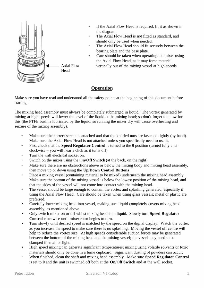
Axial FlowHead
• If the Axial Flow Head is required, fit it as shown inthe diagram.
• The Axial Flow Head is not fitted as standard, andshould only be used when needed.
• The Axial Flow Head should fit securely between thebearing plate and the base plate.
• Care should be taken when operating the mixer usingthe Axial Flow Head, as it may force materialvertically out of the mixing vessel at high speeds.
INSTALLATION, OPERATING& MAINTENANCE
INSTRUCTIONS MANUAL
FOR
HIGH SHEARLABORATORY MIXER
MODELS: L4R, L4RT & L4RT- A
Silverson Machines Inc . 355 Chestnut Street . East Longmeadow . MA . 01028Tel:(413) 525 4825 . Fax:(413) 525 5804
IDENTIFICATION
ISSUE 6 - JUNE 2008 Page 1 LAB — 002 — L4R
S
This Manual is supplied in conjunction with:
Mixer Model Number:_______________ Serial Number __________________
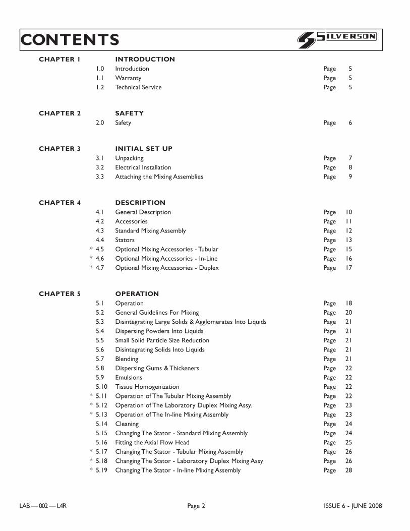
CHAPTER 1 INTRODUCTION1.0 Introduction Page 51.1 Warranty Page 51.2 Technical Service Page 5
CHAPTER 2 SAFETY2.0 Safety Page 6
CHAPTER 3 INITIAL SET UP3.1 Unpacking Page 73.2 Electrical Installation Page 83.3 Attaching the Mixing Assemblies Page 9
CHAPTER 4 DESCRIPTION4.1 General Description Page 104.2 Accessories Page 114.3 Standard Mixing Assembly Page 124.4 Stators Page 13
* 4.5 Optional Mixing Accessories - Tubular Page 15* 4.6 Optional Mixing Accessories - In-Line Page 16* 4.7 Optional Mixing Accessories - Duplex Page 17
CHAPTER 5 OPERATION5.1 Operation Page 185.2 General Guidelines For Mixing Page 205.3 Disintegrating Large Solids & Agglomerates Into Liquids Page 215.4 Dispersing Powders Into Liquids Page 215.5 Small Solid Particle Size Reduction Page 215.6 Disintegrating Solids Into Liquids Page 215.7 Blending Page 215.8 Dispersing Gums & Thickeners Page 225.9 Emulsions Page 225.10 Tissue Homogenization Page 22
* 5.11 Operation of The Tubular Mixing Assembly Page 22* 5.12 Operation of The Laboratory Duplex Mixing Assy. Page 23* 5.13 Operation of The In-line Mixing Assembly Page 23
5.14 Cleaning Page 245.15 Changing The Stator - Standard Mixing Assembly Page 245.16 Fitting the Axial Flow Head Page 25
* 5.17 Changing The Stator - Tubular Mixing Assembly Page 26* 5.18 Changing The Stator - Laboratory Duplex Mixing Assy Page 26* 5.19 Changing The Stator - In-line Mixing Assembly Page 28
CONTENTS
LAB — 002 — L4R Page 2 ISSUE 6 - JUNE 2008
S
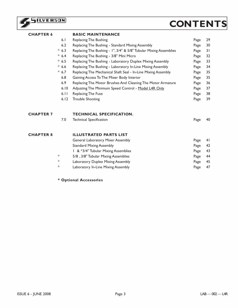
CONTENTSCHAPTER 6 BASIC MAINTENANCE
6.1 Replacing The Bushing Page 296.2 Replacing The Bushing - Standard Mixing Assembly Page 30
* 6.3 Replacing The Bushing - 1", 3/4" & 5/8" Tubular Mixing Assemblies Page 31* 6.4 Replacing The Bushing - 3/8" Mini Micro Page 32* 6.5 Replacing The Bushing - Laboratory Duplex Mixing Assembly Page 33* 6.6 Replacing The Bushing - Laboratory In-Line Mixing Assembly Page 34* 6.7 Replacing The Mechanical Shaft Seal - In-Line Mixing Assembly Page 35
6.8 Gaining Access To The Mixer Body Interior Page 356.9 Replacing The Motor Brushes And Cleaning The Motor Armature Page 366.10 Adjusting The Minimum Speed Control - Model L4R Only Page 376.11 Replacing The Fuse Page 386.12 Trouble Shooting Page 39
CHAPTER 7 TECHNICAL SPECIFICATION.7.0 Technical Specification Page 40
CHAPTER 8 ILLUSTRATED PARTS LISTGeneral Laboratory Mixer Assembly Page 41Standard Mixing Assembly Page 421Ó & *3/4" Tubular Mixing Assemblies Page 43
* 5/8Ó, 3/8" Tubular Mixing Assemblies Page 44* Laboratory Duplex Mixing Assembly Page 45* Laboratory In-Line Mixing Assembly Page 47
* Optional Accessories
ISSUE 6 - JUNE 2008 Page 3 LAB — 002 — L4R
S
LIST OF ILLUSTRATIONSFig. No. Page No.
1 Unpacking The Mixer 7
2 Fitting The Standard Mixing Frame 9
3 The Lab Mixer Assembly 10
4 Standard Mixing Assembly 12
* 5 Tubular Mixing Assemblies 15
* 6 Laboratory In-Line Mixing Assembly 16
* 7 Laboratory Duplex Mixing Assembly 17
8 Operating The L4R 18 & 19
9 Mixing Techniques 20
10 Changing The Stator - Standard Mixing Assembly 24
11 Fitting The Axial Flow Head 25
* 12 Changing The Stator - Tubular Mixing Assemblies 26
* 13 Changing The Lower Stator - Duplex Mixing Assy 26
* 14 Changing The Upper Stator - Duplex Mixing Assy 27
* 15 Changing The Stator - In-line Mixing Assemblies 28
16 Replacing The Bushing of The Standard Mixing Assembly 30
* 17 Replacing The Bushing of The 1", 3/4" and 5/8" Tubular Mixing Assy 31
* 18 Replacing The Bushing of The 3/8" Mini Micro Tubular Mixing Assy 32
* 19 Replacing The Bushing of The Laboratory Duplex Mixing Assembly 33
* 20 Laboratory In-Line Mixing Assembly 34
* 21 Replacing The Mechanical Shaft Seal - In-Line Mixing Assembly 35
22 Gaining Access To The Mixer Body 35
23 Replacing The Motor Brushes 36
24 Adjusting The Minimum Speed Control 37
25 Dimensions 40
INDEX
LAB — 002 — L4R Page 4 ISSUE 6 - JUNE 2008
S
1.0 INTRODUCTION
The purpose of this manual is to provide you with the information need to set up and operate your SilversonLaboratory Mixer.
With over 50 years of manufacturing experience Silverson has established an unequalled reputation for quality andreliability and we want you to get the best possible performance from your mixer.
IMPORTANT: Please read this manual carefully before attempting to set up or operate yourmachine. Neither Silverson Machines or their representatives can accept responsibility fordamage or injury resulting form improper set up or use. If you have any questions, pleasecontact our Technical Service Department or our representatives, who will be pleased to helpyou.
1.1 WARRANTY
Silverson Machines Inc. offers comprehensive after-sales services. If any major fault develops, the mixer should bereturned for repair and / or service.
The nature of the fault should be fully described and the model and serial number of the machine quoted in anyaccompanying correspondence.
Repair or replacement under warranty will be effected without charge for up to 1 year from the date of purchaseprovided that the foregoing provisions are complied with.
The mixer must only be shipped suitably packed with the approval of Silverson Machines or their accreditedrepresentatives.
1.2 TECHNICAL SERVICE
Spare parts and advice regarding the operation of your machine can be obtained from the service department:
SILVERSON MACHINES INC. TEL: (413) 525 4825
P.O. BOX 589 FAX: (413) 525 5804
355 CHESTNUT STREET
EAST LONGMEADOW, MA 01028 or our appointed agents.
IMPORTANT: If you require spare parts or after sales service or assistance, please specify themachine model number and serial number; these are the numbers on the name plate attachedto the rear panel of the mixer body.
Note:When returning a unit for inspection/repair, ship the mixer: ATTN: REPAIRS, with a letter including your name,telephone number and description of problem.
1.0 INTRODUCTION
ISSUE 6 - JUNE 2008 Page 5 LAB — 002 — L4R
S
Silverson Machines Inc.P.O. Box 589,355 Chestnut Street,East Longmeadow, MA 01028Tel: (413) 525 4825
HEAVY DUTYLABORATORY MIXER EMULSIFIER
Model Serial No.
ISOLATE BEFORE REMOVING COVER
Made in England
2.0 SAFETY
2.1 Throughout this manual you will find safety signs which are classified according to the relative seriousness of the hazardsituation. The determination is based on what could happen as a result of exposure to the hazard. There are threehazard classifications which are denoted by the signal words DANGER, WARNING or CAUTION. Signs whichare denoted as NOTICE indicate that the machine may be damaged if care is not taken when performing theprocedure.
DANGER: INDICATES AN IMMINENTLY HAZARDOUS SITUATION WHICH, IF NOTAVOIDED, WILL RESULT IN DEATH OR SERIOUS INJURY.
WARNING: INDICATES A POTENTIALLY HAZARDOUS SITUATION WHICH, IF NOTAVOIDED, COULD RESULT IN DEATH OR SERIOUS INJURY.
CAUTION: Indicates a potentially hazardous situation which, if not avoided, may result inminor or moderate injury. It may also be used to alert against unsafe practices.
NOTICE: indicates that the machine may be damaged if care is not taken when performing theprocedure.
2.2 PRIOR TO UNPACKING THE LABORATORY MIXER: To avoid damaging the mixing unit refer to chapter 3.1 of thisManual for step by step instructions for unpacking the unit.
2.3 Please observe the Health and Safety regulations applicable to your particular location; these vary from country tocountry but their substance is the same - avoid all hazards to personnel and property.
2.4 WARNING: DO NOT USE THE MACHINE IN A HAZARDOUS AREA WHERE A FLAMMABLEOR EXPLOSIVE ATMOSPHERE MAY BE PRESENT. THIS MACHINE IS NOT EXPLOSIONPROOF / FLAME PROOF.
2.5 WARNING: NEVER TOUCH ROTATING PARTS. FAILURE TO OBSERVE THIS MAY RESULT INBODILY INJURY.
CAUTION: Use special care when handling the Mixing Assemblies - THEY MAY BE SHARP!
2.6 WARNING: IF USING SOLVENTS TO CLEAN COMPONENTS, USE IN A WELL VENTILATEDAREA AND AVOID INHALATION OF FUMES. KEEP AWAY FROM SOURCES OF IGNITION :-NO SMOKING.
2.7 Never use parts other than those supplied or recommended by Silverson Machines Inc. The use of such parts willnullify any warranties and may cause premature wear or more seriously may cause component failure and possibleinjury.
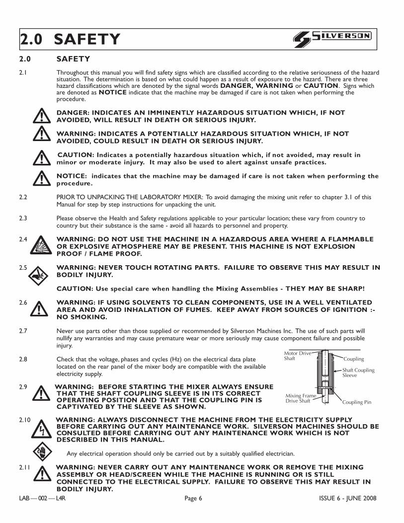
2.8 Check that the voltage, phases and cycles (Hz) on the electrical data platelocated on the rear panel of the mixer body are compatible with the availableelectricity supply.
2.9 WARNING: BEFORE STARTING THE MIXER ALWAYS ENSURETHAT THE SHAFT COUPLING SLEEVE IS IN ITS CORRECTOPERATING POSITION AND THAT THE COUPLING PIN ISCAPTIVATED BY THE SLEEVE AS SHOWN.
2.10 WARNING: ALWAYS DISCONNECT THE MACHINE FROM THE ELECTRICITY SUPPLYBEFORE CARRYING OUT ANY MAINTENANCE WORK. SILVERSON MACHINES SHOULD BECONSULTED BEFORE CARRYING OUT ANY MAINTENANCE WORK WHICH IS NOTDESCRIBED IN THIS MANUAL.
Any electrical operation should only be carried out by a suitably qualified electrician.
2.11 WARNING: NEVER CARRY OUT ANY MAINTENANCE WORK OR REMOVE THE MIXINGASSEMBLY OR HEAD/SCREEN WHILE THE MACHINE IS RUNNING OR IS STILLCONNECTED TO THE ELECTRICAL SUPPLY. FAILURE TO OBSERVE THIS MAY RESULT INBODILY INJURY.
!EF!
!CB
!!!!
2.0 SAFETY
LAB — 002 — L4R Page 6 ISSUE 6 - JUNE 2008
S
Coupling Pin
Shaft CouplingSleeve
CouplingMotor DriveShaft
Mixing FrameDrive Shaft
C0012
Goupille
Cache Goupille
Arbre Moteur
Arbre/Rotor
Accouplement
French
14
Motor Drive Shaft
1.7/8”(47.6 mm)
9
14
Pasador deenganche
Uni�n
Spanish
Eje conductordel motor.
Manguito deacoplamiento al eje
Eje conductor de laestructura del mezclador.
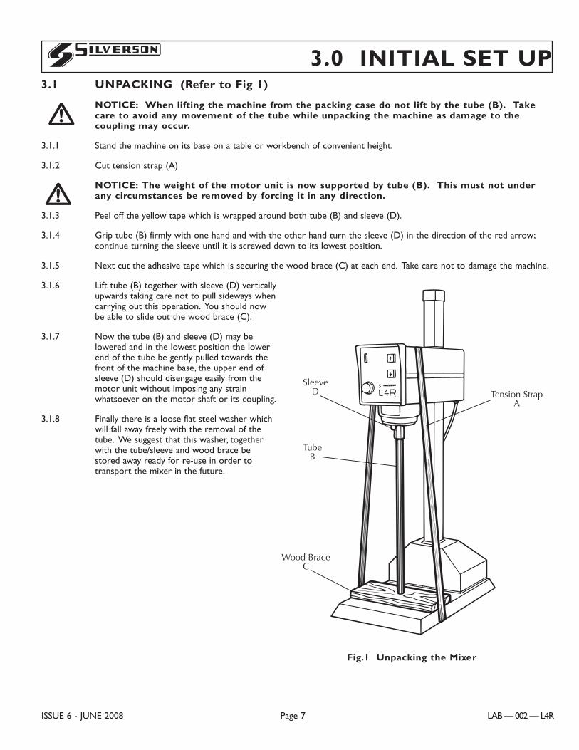
3.0 INITIAL SET UP3.1 UNPACKING (Refer to Fig 1)
NOTICE: When lifting the machine from the packing case do not lift by the tube (B). Takecare to avoid any movement of the tube while unpacking the machine as damage to thecoupling may occur.
3.1.1 Stand the machine on its base on a table or workbench of convenient height.
3.1.2 Cut tension strap (A)
NOTICE: The weight of the motor unit is now supported by tube (B). This must not underany circumstances be removed by forcing it in any direction.
3.1.3 Peel off the yellow tape which is wrapped around both tube (B) and sleeve (D).
3.1.4 Grip tube (B) firmly with one hand and with the other hand turn the sleeve (D) in the direction of the red arrow;continue turning the sleeve until it is screwed down to its lowest position.
3.1.5 Next cut the adhesive tape which is securing the wood brace (C) at each end. Take care not to damage the machine.
3.1.6 Lift tube (B) together with sleeve (D) verticallyupwards taking care not to pull sideways whencarrying out this operation. You should nowbe able to slide out the wood brace (C).
3.1.7 Now the tube (B) and sleeve (D) may belowered and in the lowest position the lowerend of the tube be gently pulled towards thefront of the machine base, the upper end ofsleeve (D) should disengage easily from themotor unit without imposing any strainwhatsoever on the motor shaft or its coupling.
3.1.8 Finally there is a loose flat steel washer whichwill fall away freely with the removal of thetube. We suggest that this washer, togetherwith the tube/sleeve and wood brace bestored away ready for re-use in order totransport the mixer in the future.
!
!
ISSUE 6 - JUNE 2008 Page 7 LAB — 002 — L4R
S
Tension StrapA
Wood BraceC
TubeB
SleeveD
Fig.1 Unpacking the Mixer
3.2 ELECTRICAL CONNECTION
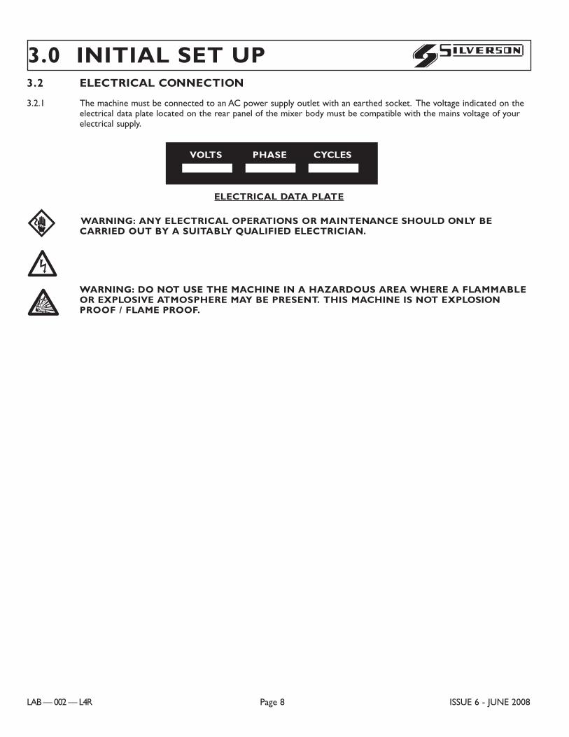
3.2.1 The machine must be connected to an AC power supply outlet with an earthed socket. The voltage indicated on theelectrical data plate located on the rear panel of the mixer body must be compatible with the mains voltage of yourelectrical supply.
WARNING: ANY ELECTRICAL OPERATIONS OR MAINTENANCE SHOULD ONLY BECARRIED OUT BY A SUITABLY QUALIFIED ELECTRICIAN.
WARNING: DO NOT USE THE MACHINE IN A HAZARDOUS AREA WHERE A FLAMMABLEOR EXPLOSIVE ATMOSPHERE MAY BE PRESENT. THIS MACHINE IS NOT EXPLOSIONPROOF / FLAME PROOF.B
FE
3.0 INITIAL SET UP
LAB — 002 — L4R Page 8 ISSUE 6 - JUNE 2008
S
VOLTS PHASE CYCLES
ELECTRICAL DATA PLATE
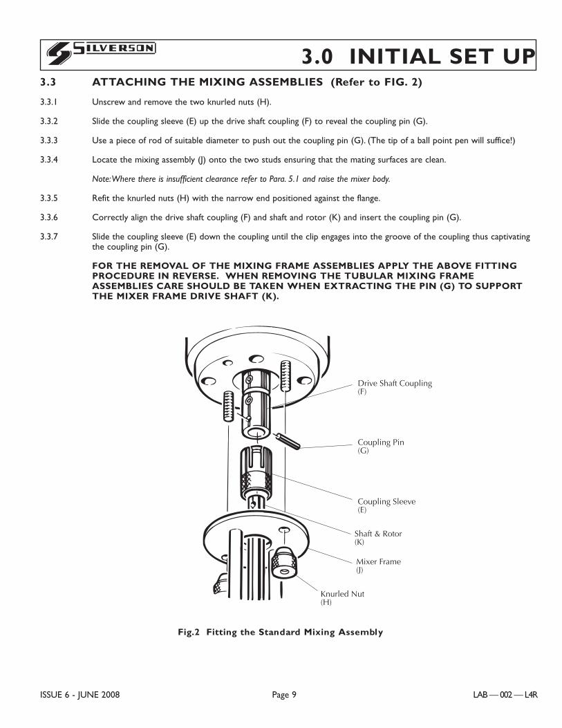
3.0 INITIAL SET UP3.3 ATTACHING THE MIXING ASSEMBLIES (Refer to FIG. 2)
3.3.1 Unscrew and remove the two knurled nuts (H).
3.3.2 Slide the coupling sleeve (E) up the drive shaft coupling (F) to reveal the coupling pin (G).
3.3.3 Use a piece of rod of suitable diameter to push out the coupling pin (G). (The tip of a ball point pen will suffice!)
3.3.4 Locate the mixing assembly (J) onto the two studs ensuring that the mating surfaces are clean.
Note:Where there is insufficient clearance refer to Para. 5.1 and raise the mixer body.
3.3.5 Refit the knurled nuts (H) with the narrow end positioned against the flange.
3.3.6 Correctly align the drive shaft coupling (F) and shaft and rotor (K) and insert the coupling pin (G).
3.3.7 Slide the coupling sleeve (E) down the coupling until the clip engages into the groove of the coupling thus captivatingthe coupling pin (G).
FOR THE REMOVAL OF THE MIXING FRAME ASSEMBLIES APPLY THE ABOVE FITTINGPROCEDURE IN REVERSE. WHEN REMOVING THE TUBULAR MIXING FRAMEASSEMBLIES CARE SHOULD BE TAKEN WHEN EXTRACTING THE PIN (G) TO SUPPORTTHE MIXER FRAME DRIVE SHAFT (K).
ISSUE 6 - JUNE 2008 Page 9 LAB — 002 — L4R
S
C0131
Drive Shaft Coupling(F)
Coupling Pin(G)
Coupling Sleeve(E)
Shaft & Rotor(K)
Mixer Frame(J)
Knurled Nut(H)
Fig.2 Fitting the Standard Mixing Assembly
4.1 GENERAL
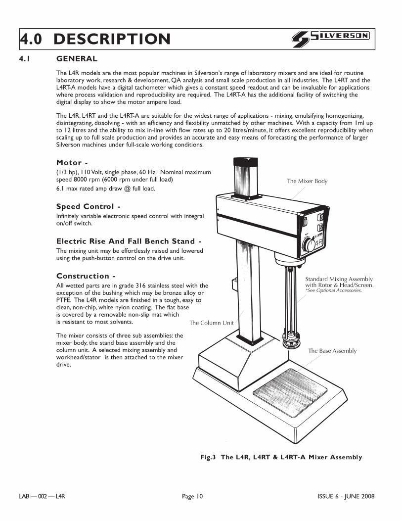
The L4R models are the most popular machines in Silverson’s range of laboratory mixers and are ideal for routinelaboratory work, research & development, QA analysis and small scale production in all industries. The L4RT and theL4RT-A models have a digital tachometer which gives a constant speed readout and can be invaluable for applicationswhere process validation and reproducibility are required. The L4RT-A has the additional facility of switching thedigital display to show the motor ampere load.
The L4R, L4RT and the L4RT-A are suitable for the widest range of applications - mixing, emulsifying homogenizing,disintegrating, dissolving - with an efficiency and flexibility unmatched by other machines. With a capacity from 1ml upto 12 litres and the ability to mix in-line with flow rates up to 20 litres/minute, it offers excellent reproducibility whenscaling up to full scale production and provides an accurate and easy means of forecasting the performance of largerSilverson machines under full-scale working conditions.
Motor - (1/3 hp), 110 Volt, single phase, 60 Hz. Nominal maximumspeed 8000 rpm (6000 rpm under full load)6.1 max rated amp draw @ full load.
Speed Control -Infinitely variable electronic speed control with integralon/off switch.
Electric Rise And Fall Bench Stand -The mixing unit may be effortlessly raised and loweredusing the push-button control on the drive unit.
Construction -All wetted parts are in grade 316 stainless steel with theexception of the bushing which may be bronze alloy orPTFE. The L4R models are finished in a tough, easy toclean, non-chip, white nylon coating. The flat baseis covered by a removable non-slip mat whichis resistant to most solvents.
The mixer consists of three sub assemblies: themixer body, the stand base assembly and thecolumn unit. A selected mixing assembly andworkhead/stator is then attached to the mixerdrive.
4.0 DESCRIPTION
LAB — 002 — L4R Page 10 ISSUE 6 - JUNE 2008
S
The Mixer Body
The Column Unit
Standard Mixing Assemblywith Rotor & Head/Screen.*See Optional Accessories.
The Base Assembly
C0083 (L4 BASE MAN.)
Fig.3 The L4R, L4RT & L4RT-A Mixer Assembly
4.0 DESCRIPTION4.1.1 THE MIXER BODY
The mixer drive body consists of a lower casing and a top cover to which the front and rear end panels are attached.This body is mounted to a carriage assembly which when electrically operated travels vertically up/down the columnunit.
The mixer body houses the mixer motor, control units, the fuse and electrical wiring for these components. Sealingstrips and bezels are fitted to the body casing.
The front panel carries the rise and fall control push buttons, the combined on/off switch and speed control and the’power on’ indicator lamp. On the L4RT and L4RT-A the digital tachometer is also located on the front panel.
The rear panel carries the fuse holder and the serial number plate.
4.1.2 THE STAND BASE ASSEMBLY
The base assembly, to which the column unit is mounted, serves as a platform for mixing containers, a removablenon-slip mat is also provided.
The rise and fall motor and its associated capacitor(s), the rise/fall limit switch, the combined ’power on’ switch withintegral safety cut-out device and the electrical wiring for these components are located at the base of the columnand housed inside the base cover.
A sealing strip and bezel are fitted to the cover plate to form a splash proof enclosure.
!WARNING:THE ENCLOSURE IS NOT WATERPROOF, HOSE PROOF OR WEATHERPROOF.
4.1.3. THE COLUMN UNIT
The mixer body and the base assembly are connected by the column unit which houses components for the rise/fallmechanism.
A spring-loaded stop plunger is fitted to the rear of the column; this is a fail safe device which inhibits the downwardtravel of the mixer body in the unlikely event of drive chain failure.
4.2 ACCESSORIES
The L4R, L4RT and the L4RT-A are normally supplied with a standard two arm mixing assembly and a selection ofinterchangeable workheads/stators as shown on FIG. 4. All of the optional accessories described in the followingparagraphs are interchangeable with the standard mixing assembly and available as optional extras. SilversonMachines, Inc. will be pleased to advise and quote for your specific requirements. When interchanging mixingassemblies please refer to the Ôinitial set upÕ section of this manual for instructions. The Operation section of thismanual recommends which workhead/stator should be used with certain mixing techniques and details how to changethe workhead/stator.
ISSUE 6 - JUNE 2008 Page 11 LAB — 002 — L4R
S
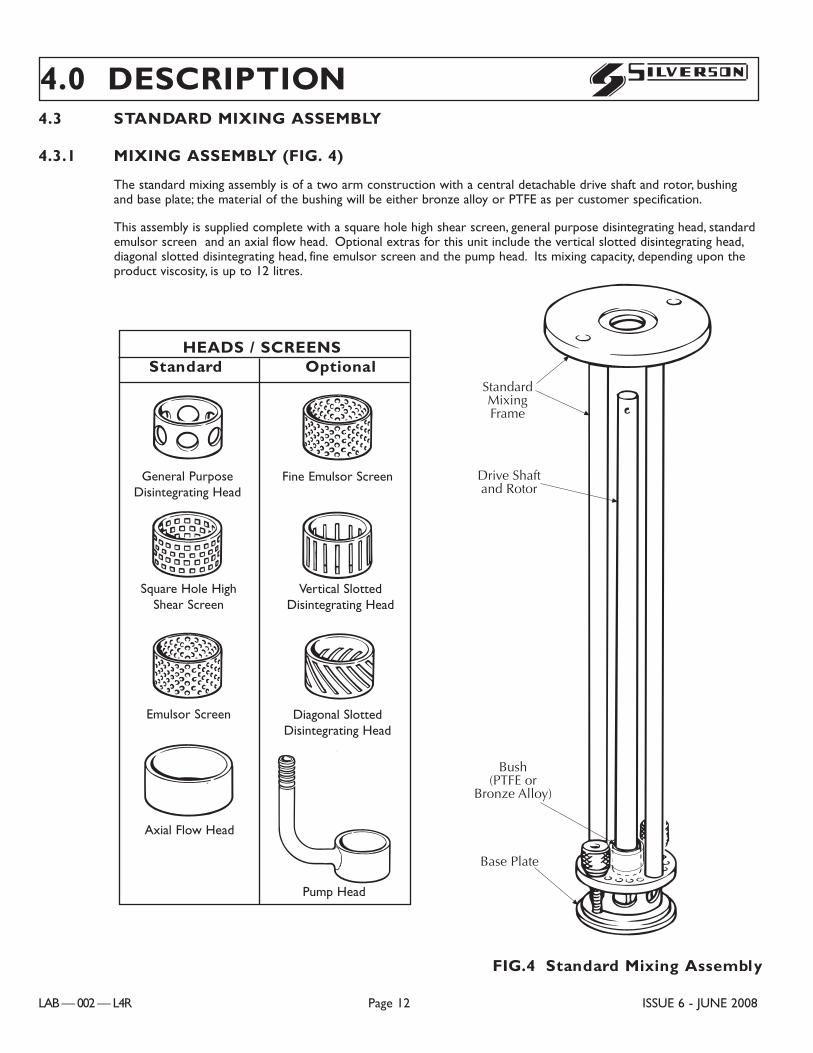
4.3 STANDARD MIXING ASSEMBLY
4.3.1 MIXING ASSEMBLY (FIG. 4)
The standard mixing assembly is of a two arm construction with a central detachable drive shaft and rotor, bushingand base plate; the material of the bushing will be either bronze alloy or PTFE as per customer specification.
This assembly is supplied complete with a square hole high shear screen, general purpose disintegrating head, standardemulsor screen and an axial flow head. Optional extras for this unit include the vertical slotted disintegrating head,diagonal slotted disintegrating head, fine emulsor screen and the pump head. Its mixing capacity, depending upon theproduct viscosity, is up to 12 litres.
4.0 DESCRIPTION
LAB — 002 — L4R Page 12 ISSUE 6 - JUNE 2008
S
C0084
StandardMixingFrame
Drive Shaftand Rotor
Bush(PTFE or
Bronze Alloy)
Base Plate
C0043
C0084
C0084
C0084
C0084
C0084
C0084
C0084
General PurposeDisintegrating Head
Emulsor Screen
Square Hole HighShear Screen
Axial Flow Head
Fine Emulsor Screen
Vertical SlottedDisintegrating Head
Diagonal SlottedDisintegrating Head
Pump Head
HEADS / SCREENSStandard Optional
FIG.4 Standard Mixing Assembly
DANGER, WARNING AND CAUTIONS are given to alert to hazardous situations which may result physical injury.NOTICES are given to alert to situations which may result in damage to the Mixer.!
ISSUE 6 - JUNE 2008 Page 13 LAB — 002 — L4R
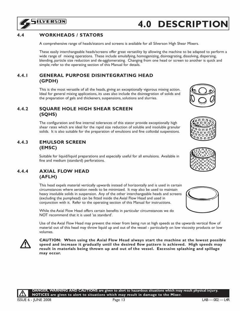
S 4.0 DESCRIPTION4.4 WORKHEADS / STATORS
A comprehensive range of heads/stators and screens is available for all Silverson High Shear Mixers.
These easily interchangeable heads/screens offer great versatility by allowing the machine to be adapted to perform awide range of mixing operations. These include emulsifying, homogenizing, disintegrating, dissolving, dispersing,blending, particle size reduction and de-agglomerating. Changing from one head or screen to another is quick andsimple; refer to the operating section of this Manual for details.
4.4.1 GENERAL PURPOSE DISINTEGRATING HEAD(GPDH)
This is the most versatile of all the heads, giving an exceptionally vigorous mixing action.Ideal for general mixing applications, its uses also include the disintegration of solids andthe preparation of gels and thickeners, suspensions, solutions and slurries.
4.4.2 SQUARE HOLE HIGH SHEAR SCREEN(SQHS)
The configuration and fine internal tolerances of this stator provide exceptionally highshear rates which are ideal for the rapid size reduction of soluble and insoluble granularsolids. It is also suitable for the preparation of emulsions and fine colloidal suspensions.
4.4.3 EMULSOR SCREEN(EMSC)
Suitable for liquid/liquid preparations and especially useful for all emulsions. Available infine and medium (standard) perforations.
4.4.4 AXIAL FLOW HEAD(AFLH)
This head expels material vertically upwards instead of horizontally and is used in certaincircumstances where aeration needs to be minimized. It may also be used to maintainheavy insoluble solids in suspension. Any of the other interchangeable heads and screens(excluding the pumphead) can be fitted inside the Axial Flow Head and used inconjunction with it. Refer to the operating section of this Manual for instructions.
While the Axial Flow Head offers certain benefits in particular circumstances we doNOT recommend that it is used ’as standard’.
Use of the Axial Flow Head may prevent the mixer from being run at high speeds as the upwards vertical flow ofmaterial out of this head may throw liquid up and out of the vessel - particularly on low viscosity products or lowvolumes.
CAUTION: When using the Axial Flow Head always start the machine at the lowest possiblespeed and increase it gradually until the desired flow pattern is achieved. High speeds mayresult in materials being thrown up and out of the vessel. Excessive splashing and spillagemay occur.
!
C0084
C0084
C0084
C0084
LAB — 002 — L4R Page 14 ISSUE 6 - JUNE 2008
DANGER, WARNING AND CAUTIONS are given to alert to hazardous situations which may result physical injuryNOTICES are given to alert to situations which may result in damage to the Mixer.!
S4.0 DESCRIPTION
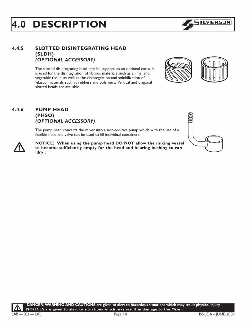
4.4.5 SLOTTED DISINTEGRATING HEAD (SLDH)(OPTIONAL ACCESSORY)
The slotted disintegrating head may be supplied as an optional extra. Itis used for the disintegration of fibrous materials such as animal andvegetable tissue, as well as the disintegration and solubilization of’elastic’ materials such as rubbers and polymers. Vertical and diagonalslotted heads are available.
4.4.6 PUMP HEAD (PHSO)(OPTIONAL ACCESSORY)
The pump head converts the mixer into a non-positive pump which with the use of aflexible hose and valve can be used to fill individual containers.
NOTICE: When using the pump head DO NOT allow the mixing vesselto become sufficiently empty for the head and bearing bushing to run’dry’.!
C0084
C0084
C0084
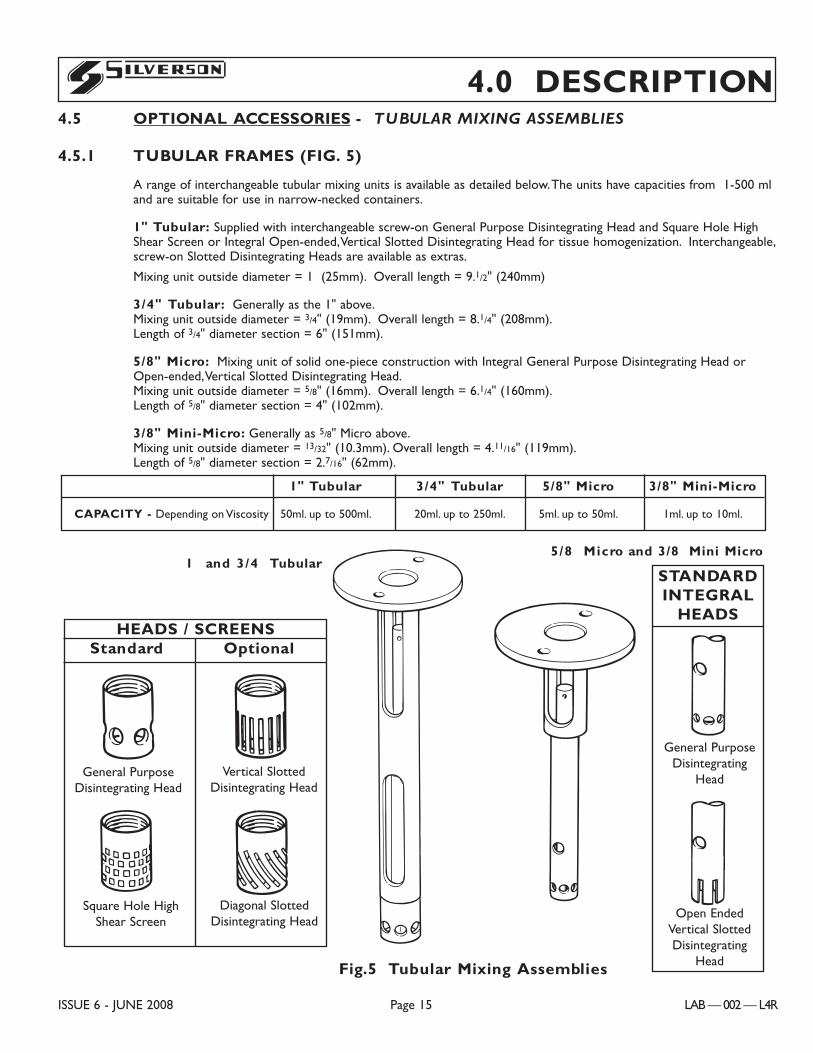
4.0 DESCRIPTION4.5 OPTIONAL ACCESSORIES - TUBULAR MIXING ASSEMBLIES
4.5.1 TUBULAR FRAMES (FIG. 5)
A range of interchangeable tubular mixing units is available as detailed below.The units have capacities from 1-500 mland are suitable for use in narrow-necked containers.
1" Tubular: Supplied with interchangeable screw-on General Purpose Disintegrating Head and Square Hole HighShear Screen or Integral Open-ended,Vertical Slotted Disintegrating Head for tissue homogenization. Interchangeable,screw-on Slotted Disintegrating Heads are available as extras.
Mixing unit outside diameter = 1Ó (25mm). Overall length = 9.1/2" (240mm)
3/4" Tubular: Generally as the 1" above.Mixing unit outside diameter = 3/4" (19mm). Overall length = 8.1/4" (208mm).Length of 3/4" diameter section = 6" (151mm).
5/8" Micro: Mixing unit of solid one-piece construction with Integral General Purpose Disintegrating Head orOpen-ended,Vertical Slotted Disintegrating Head.Mixing unit outside diameter = 5/8" (16mm). Overall length = 6.1/4" (160mm).Length of 5/8" diameter section = 4" (102mm).
3/8" Mini-Micro: Generally as 5/8" Micro above.Mixing unit outside diameter = 13/32" (10.3mm). Overall length = 4.11/16" (119mm).Length of 5/8" diameter section = 2.7/16" (62mm).
ISSUE 6 - JUNE 2008 Page 15 LAB — 002 — L4R
S
1" Tubular 3/4" Tubular 5/8" Micro 3/8" Mini-Micro
CAPACITY - Depending on Viscosity 50ml. up to 500ml. 20ml. up to 250ml. 5ml. up to 50ml. 1ml. up to 10ml.
C0103
C0084
C0084C0084
C0084
C0132C0133
Fig.5 Tubular Mixing Assemblies
1 Ó and 3/4Ó Tubular5/8Ó Micro and 3/8Ó Mini Micro
HEADS / SCREENSStandard Optional
General PurposeDisintegrating Head
Square Hole HighShear Screen
Vertical SlottedDisintegrating Head
Diagonal SlottedDisintegrating Head
General PurposeDisintegrating
Head
Open EndedVertical SlottedDisintegrating
Head
STANDARDINTEGRAL
HEADS
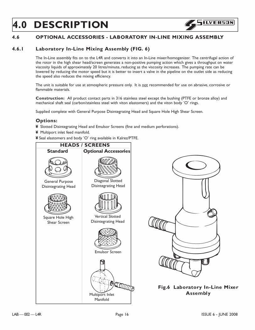
4.6 OPTIONAL ACCESSORIES - LABORATORY IN-LINE MIXING ASSEMBLY
4.6.1 Laboratory In-Line Mixing Assembly (FIG. 6)
The In-Line assembly fits on to the L4R and converts it into an In-Line mixer/homogenizer. The centrifugal action ofthe rotor in the high shear head/screen generates a non-positive pumping action which gives a throughput on waterviscosity liquids of approximately 20 litres/minute, reducing as the viscosity increases. The pumping rate can belowered by reducing the motor speed but it is better to insert a valve in the pipeline on the outlet side as reducingthe speed also reduces the mixing efficiency.
The unit is suitable for use at atmospheric pressure only. It is not recommended for use on abrasive, corrosive orflammable materials.
Construction: All product contact parts in 316 stainless steel except the bushing (PTFE or bronze alloy) andmechanical shaft seal (carbon/stainless steel with viton elastomers) and the viton body ’O’ rings.
Supplied complete with General Purpose Disintegrating Head and Square Hole High Shear Screen.
Options:¥ Slotted Disintegrating Head and Emulsor Screens (fine and medium perforations).¥ Multiport inlet feed manifold.¥ Seal elastomers and body ’O’ ring available in Kalrez/PTFE.
4.0 DESCRIPTION
LAB — 002 — L4R Page 16 ISSUE 6 - JUNE 2008
S
C0091
C0085
C0085
C0085
C0085
C0085
C0085
General PurposeDisintegrating Head
Square Hole HighShear Screen
Diagonal SlottedDisintegrating Head
Vertical SlottedDisintegrating Head
Emulsor Screen
Multiport InletManifold
Fig.6 Laboratory In-Line MixerAssembly
HEADS / SCREENSStandard Optional Accessories
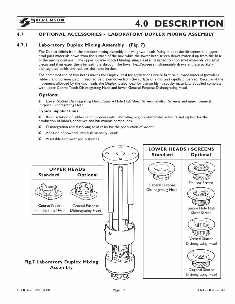
4.7 OPTIONAL ACCESSORIES - LABORATORY DUPLEX MIXING ASSEMBLY
4.7.1 Laboratory Duplex Mixing Assembly (Fig. 7)The Duplex differs from the standard mixing assembly in having two heads facing in opposite directions; the upperhead pulls materials down from the surface of the mix, while the lower head/screen draws material up from the baseof the mixing container. The upper Coarse Tooth Disintegrating Head is designed to chop solid materials into smallpieces and then expel them beneath the shroud. The lower head/screen simultaneously draws in these partiallydisintegrated solids and reduces their size further.
The combined use of two heads makes the Duplex ideal for applications where light or buoyant material (powders,rubbers and polymers, etc.) needs to be drawn down from the surface of a mix and rapidly dispersed. Because of themovement afforded by the two heads, the Duplex is also ideal for use on high viscosity materials. Supplied completewith upper Coarse Tooth Disintegrating Head and lower General Purpose Disintegrating Head
Options:¥ Lower Slotted Disintegrating Heads, Square Hole High Shear Screen, Emulsor Screens and upper GeneralPurpose Disintegrating Head.
Typical Applications:
¥ Rapid solution of rubbers and polymers into lubricating oils, non-flammable solvents and asphalt for theproduction of luboils, adhesives and bituminous compounds.
¥ Disintegration and dissolving solid resin for the production of varnish.
¥ Addition of powders into high viscosity liquids.
¥ Vegetable and meat pur�e/slurries
4.0 DESCRIPTION
ISSUE 6 - JUNE 2008 Page 17 LAB — 002 — L4R
S
C0095
C0085
C0085
Emulsor Screen
Square Hole HighShear Screen
C0085
Vertical SlottedDisintegrating Head
C0085
Diagonal SlottedDisintegrating Head
LOWER HEADS / SCREENSStandard Optional
C0085
UPPER HEADSStandard Optional
Fig.7 Laboratory Duplex MixingAssembly
General PurposeDisintegrating Head
General PurposeDisintegrating Head
Course ToothDisintegrating Head
LAB — 002 — L4R Page 18 ISSUE 6 - JUNE 2008
DANGER, WARNING AND CAUTIONS are given to alert to hazardous situations which may result physical injuryNOTICES are given to alert to situations which may result in damage to the Mixer.!
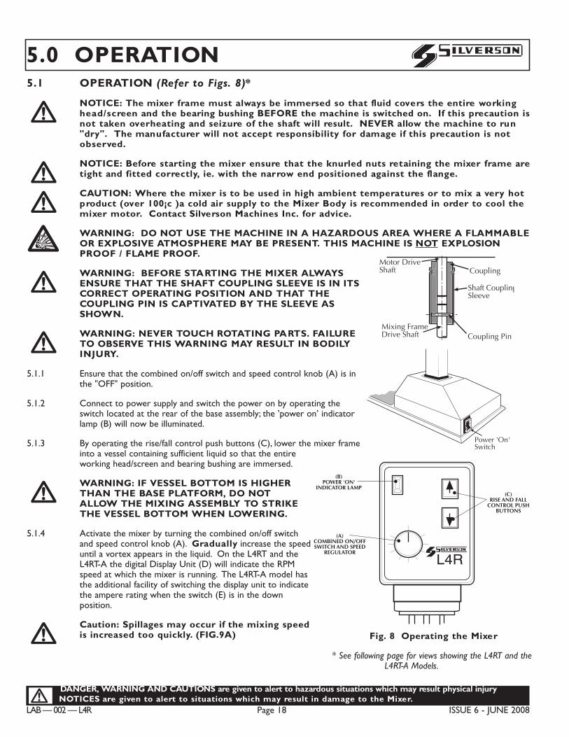
S5.0 OPERATION5.1 OPERATION (Refer to Figs. 8)*
NOTICE: The mixer frame must always be immersed so that fluid covers the entire workinghead/screen and the bearing bushing BEFORE the machine is switched on. If this precaution isnot taken overheating and seizure of the shaft will result. NEVER allow the machine to run"dry". The manufacturer will not accept responsibility for damage if this precaution is notobserved.
NOTICE: Before starting the mixer ensure that the knurled nuts retaining the mixer frame aretight and fitted correctly, ie. with the narrow end positioned against the flange.
CAUTION: Where the mixer is to be used in high ambient temperatures or to mix a very hotproduct (over 100¡c )a cold air supply to the Mixer Body is recommended in order to cool themixer motor. Contact Silverson Machines Inc. for advice.
WARNING: DO NOT USE THE MACHINE IN A HAZARDOUS AREA WHERE A FLAMMABLEOR EXPLOSIVE ATMOSPHERE MAY BE PRESENT. THIS MACHINE IS NOT EXPLOSIONPROOF / FLAME PROOF.
WARNING: BEFORE STARTING THE MIXER ALWAYSENSURE THAT THE SHAFT COUPLING SLEEVE IS IN ITSCORRECT OPERATING POSITION AND THAT THECOUPLING PIN IS CAPTIVATED BY THE SLEEVE ASSHOWN.
WARNING: NEVER TOUCH ROTATING PARTS. FAILURETO OBSERVE THIS WARNING MAY RESULT IN BODILYINJURY.
5.1.1 Ensure that the combined on/off switch and speed control knob (A) is inthe "OFF" position.
5.1.2 Connect to power supply and switch the power on by operating theswitch located at the rear of the base assembly; the ’power on’ indicatorlamp (B) will now be illuminated.
5.1.3 By operating the rise/fall control push buttons (C), lower the mixer frameinto a vessel containing sufficient liquid so that the entireworking head/screen and bearing bushing are immersed.
WARNING: IF VESSEL BOTTOM IS HIGHERTHAN THE BASE PLATFORM, DO NOTALLOW THE MIXING ASSEMBLY TO STRIKETHE VESSEL BOTTOM WHEN LOWERING.
5.1.4 Activate the mixer by turning the combined on/off switchand speed control knob (A). Gradually increase the speeduntil a vortex appears in the liquid. On the L4RT and theL4RT-A the digital Display Unit (D) will indicate the RPMspeed at which the mixer is running. The L4RT-A model hasthe additional facility of switching the display unit to indicatethe ampere rating when the switch (E) is in the downposition.
Caution: Spillages may occur if the mixing speedis increased too quickly. (FIG.9A)!
!
!!B!!!
Coupling Pin
Shaft CouplingSleeve
CouplingMotor DriveShaft
Mixing FrameDrive Shaft
C0012
Goupille
Cache Goupille
Arbre Moteur
Arbre/Rotor
Accouplement
French
14
Motor Drive Shaft
1.7/8”(47.6 mm)
9
14
Pasador deenganche
Uni�n
Spanish
Eje conductordel motor.
Manguito deacoplamiento al eje
Eje conductor de laestructura del mezclador.aaaa
Power 'On'Switchaaaa
Interrupteur
C0017
Interrupteur
Power ’On’Switch
Interrupteur
Puternic OnNuia a întrerupe
L4R
(B)POWER 'ON'
INDICATOR LAMP
(A)COMBINED ON/OFFSWITCH AND SPEED
REGULATOR
(C)RISE AND FALL
CONTROL PUSHBUTTONS
C0013
L4R
(B)Lampa
indicatoare ’ON
(A)Intrerupator combinat
ON/OFFSi regulator de viteza
(C)Buton de controlprin impingere
ridicare si
ROM
Fig. 8 Operating the Mixer
* See following page for views showing the L4RT and theL4RT-A Models.
DANGER, WARNING AND CAUTIONS are given to alert to hazardous situations which may result physical injury.NOTICES are given to alert to situations which may result in damage to the Mixer.!
ISSUE 6 - JUNE 2008 Page 19 LAB — 002 — L4R
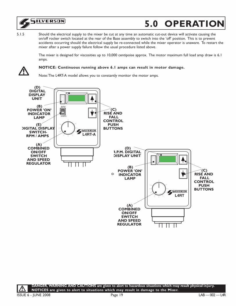
S 5.0 OPERATION5.1.5 Should the electrical supply to the mixer be cut at any time an automatic cut-out device will activate causing the
on/off rocker switch located at the rear of the Base assembly to switch into the ’off’ position. This is to preventaccidents occurring should the electrical supply be re-connected while the mixer operator is unaware. To restart themixer after a power supply failure follow the usual procedure listed above.
The mixer is designed for viscosities up to 10,000 centipoise approx. The motor maximum full load amp draw is 6.1amps.
NOTICE: Continuous running above 6.1 amps can result in motor damage.
Note:The L4RT-A model allows you to constantly monitor the motor amps.!
(B)POWER ’ON’INDICATOR
LAMP
(A)COMBINED
ON/OFFSWITCH
AND SPEEDREGULATOR
(C)RISE AND
FALLCONTROL
PUSHBUTTONS
(D)R.P.M. DIGITALDISPLAY UNIT
L4RT
(E)DIGITAL DISPLAY
SWITCH-RPM / AMPS
(B)POWER ’ON’INDICATOR
LAMP
(A)COMBINED
ON/OFFSWITCH
AND SPEEDREGULATOR
(C)RISE AND
FALLCONTROL
PUSHBUTTONS
(D) DIGITALDISPLAY
UNIT
L4RT-A
AMPS
RPM
C0015
(B)POWER ’ON’INDICATOR
LAMP
(A)COMBINED
ON/OFFSWITCH
AND SPEEDREGULATOR
(C)RISE AND
FALLCONTROL
PUSHBUTTONS
(D)R.P.M. DIGITALDISPLAY UNIT
L4RT
(E)DIGITAL DISPLAY
SWITCH-RPM / AMPS
(B)POWER ’ON’INDICATOR
LAMP
(A)COMBINED
ON/OFFSWITCH
AND SPEEDREGULATOR
(C)RISE AND
FALLCONTROL
PUSHBUTTONS
(D) DIGITALDISPLAY
UNIT
L4RT-A
AMPS
RPM
C0015
LAB — 002 — L4R Page 20 ISSUE 6 - JUNE 2008
DANGER, WARNING AND CAUTIONS are given to alert to hazardous situations which may result physical injuryNOTICES are given to alert to situations which may result in damage to the Mixer.!
S
LAB — 002 — L4R Page 20 ISSUE 5 - November 2003
5.0 OPERATION5.2 GENERAL GUIDELINES FOR MIXING (Refer to Figs. 9)
The following guidelines are designed to help you get the best results from your Silverson mixer. Due to the vastrange of mixing operations for which your mixer can be used, it is impossible to cover every eventuality and the idealmixing technique for your particular product will probably only be found after some experimentation. Should yourequire further advice then please contact Silverson Machines or their accredited agents who will be happy to helpyou achieve your required mixing results.
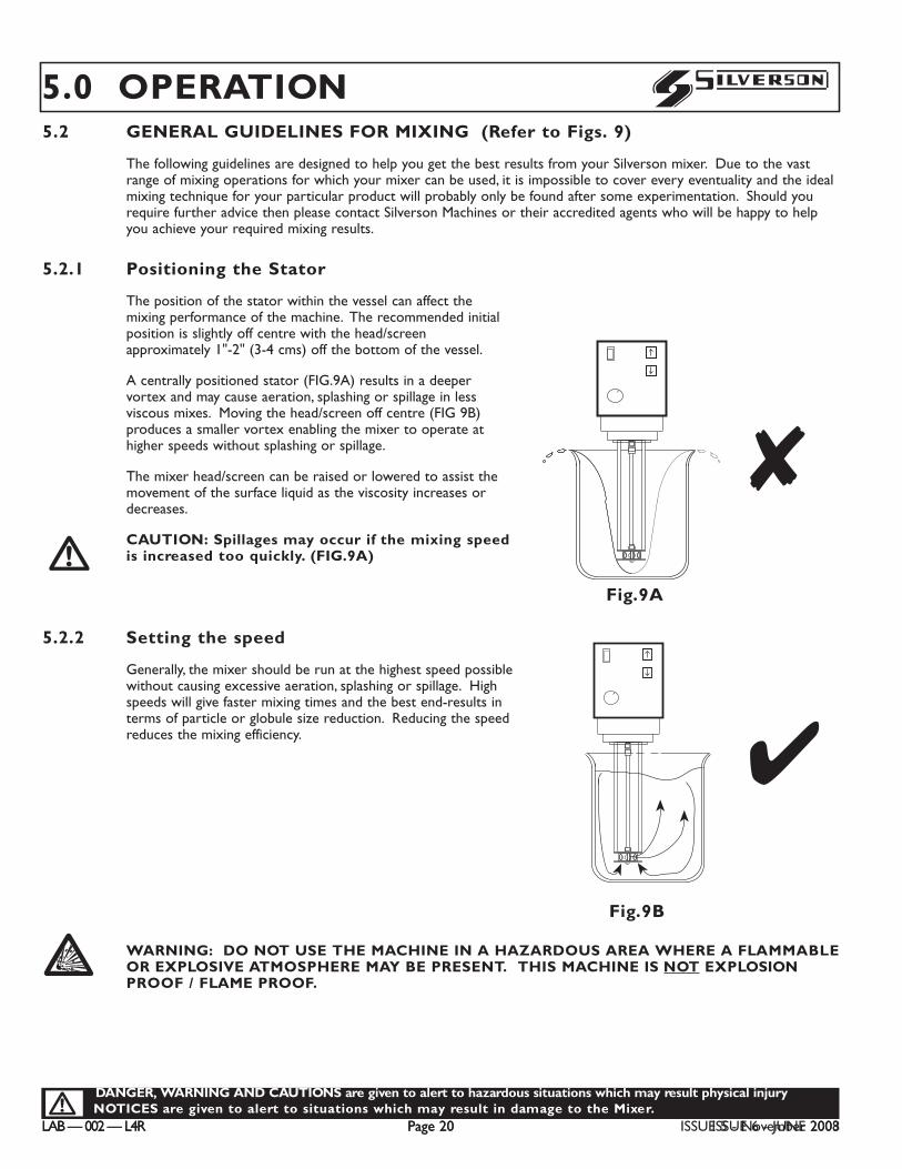
5.2.1 Positioning the Stator
The position of the stator within the vessel can affect themixing performance of the machine. The recommended initialposition is slightly off centre with the head/screenapproximately 1"-2" (3-4 cms) off the bottom of the vessel.
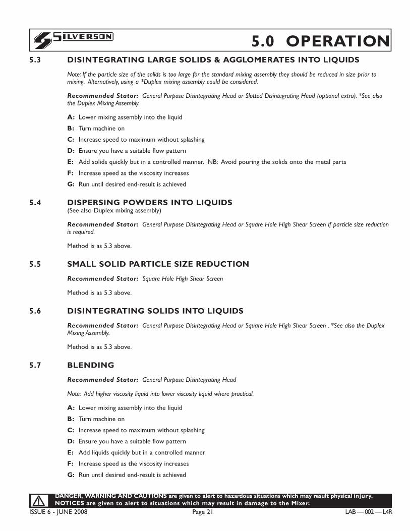
A centrally positioned stator (FIG.9A) results in a deepervortex and may cause aeration, splashing or spillage in lessviscous mixes. Moving the head/screen off centre (FIG 9B)produces a smaller vortex enabling the mixer to operate athigher speeds without splashing or spillage.
The mixer head/screen can be raised or lowered to assist themovement of the surface liquid as the viscosity increases ordecreases.
CAUTION: Spillages may occur if the mixing speedis increased too quickly. (FIG.9A)
5.2.2 Setting the speed
Generally, the mixer should be run at the highest speed possiblewithout causing excessive aeration, splashing or spillage. Highspeeds will give faster mixing times and the best end-results interms of particle or globule size reduction. Reducing the speedreduces the mixing efficiency.
WARNING: DO NOT USE THE MACHINE IN A HAZARDOUS AREA WHERE A FLAMMABLEOR EXPLOSIVE ATMOSPHERE MAY BE PRESENT. THIS MACHINE IS NOT EXPLOSIONPROOF / FLAME PROOF.
B
!
C0023
C0023
4
8
Fig.9A
Fig.9B
DANGER, WARNING AND CAUTIONS are given to alert to hazardous situations which may result physical injury.NOTICES are given to alert to situations which may result in damage to the Mixer.!
ISSUE 6 - JUNE 2008 Page 21 LAB — 002 — L4R
S 5.0 OPERATION5.3 DISINTEGRATING LARGE SOLIDS & AGGLOMERATES INTO LIQUIDS
Note: If the particle size of the solids is too large for the standard mixing assembly they should be reduced in size prior tomixing. Alternatively, using a *Duplex mixing assembly could be considered.
Recommended Stator: General Purpose Disintegrating Head or Slotted Disintegrating Head (optional extra). *See alsothe Duplex Mixing Assembly.
A: Lower mixing assembly into the liquid
B: Turn machine on
C: Increase speed to maximum without splashing
D: Ensure you have a suitable flow pattern
E: Add solids quickly but in a controlled manner. NB: Avoid pouring the solids onto the metal parts
F: Increase speed as the viscosity increases
G: Run until desired end-result is achieved
5.4 DISPERSING POWDERS INTO LIQUIDS (See also Duplex mixing assembly)
Recommended Stator: General Purpose Disintegrating Head or Square Hole High Shear Screen if particle size reductionis required.
Method is as 5.3 above.
5.5 SMALL SOLID PARTICLE SIZE REDUCTION
Recommended Stator: Square Hole High Shear Screen
Method is as 5.3 above.
5.6 DISINTEGRATING SOLIDS INTO LIQUIDS
Recommended Stator: General Purpose Disintegrating Head or Square Hole High Shear Screen . *See also the DuplexMixing Assembly.
Method is as 5.3 above.
5.7 BLENDING
Recommended Stator: General Purpose Disintegrating Head
Note: Add higher viscosity liquid into lower viscosity liquid where practical.
A: Lower mixing assembly into the liquid
B: Turn machine on
C: Increase speed to maximum without splashing
D: Ensure you have a suitable flow pattern
E: Add liquids quickly but in a controlled manner
F: Increase speed as the viscosity increases
G: Run until desired end-result is achieved
LAB — 002 — L4R Page 22 ISSUE 6 - JUNE 2008
DANGER, WARNING AND CAUTIONS are given to alert to hazardous situations which may result physical injuryNOTICES are given to alert to situations which may result in damage to the Mixer.!
S5.0 OPERATION5.8 DISPERSING GUMS & THICKENERS
(See also Duplex mixing assembly)
Recommended Stator: General Purpose Disintegrating Head or Square Hole High Shear Screen.
A: Lower mixing assembly into the liquid
B: Turn machine on
C: Increase speed to maximum without splashing
D: Ensure you have a suitable flow pattern
E: Add gums & thickeners quickly but in a controlled manner. Do not add them slowly. NB: Avoid pouring the solids onto the metal parts
F: Increase speed as the viscosity increases
5.9 EMULSIONS
Recommended Stator: Square Hole High Shear Screen or Emulsor Screen.Fine Emulsor Screen - optional extra.
Common emulsions are either oil into an aqueous phase or an aqueous phase into oil. An emulsification agent isrequired in order to produce a stable product.
A: Lower the mixing assembly into the continuous phase (water for an oil in water emulsion or oil for a water in oil emulsion).
B: Turn machine on
C: Increase speed to maximum without splashing
D: Ensure you have a suitable flow pattern
E: Add suspended phase (oil for an oil in water emulsion or water for a water in oil emulsion)
F: Increase speed as the viscosity increases
G: Run until desired end-result is achieved
H: The longer the mixer operates the more uniform the suspended particle size will be
5.10 TISSUE HOMOGENISATION
Use: Tubular mixing assembly with integral open ended Slotted Disintegrating Head
A: Add solids into liquid
B: Raise mixing container up to the mixing assembly
C: Ensure mixing assembly is submerged in the liquid
D: Position solids so they are at the base of the mixing assembly - just below the Slotted Disintegrating Head teeth
E: Turn machine on
F: Increase speed to maximum without splashing
G: Run until desired end-result is achieved
5.11 TUBULAR MIXING ASSEMBLIES
Operation as Standard Mixing Assembly.
DANGER, WARNING AND CAUTIONS are given to alert to hazardous situations which may result physical injury.NOTICES are given to alert to situations which may result in damage to the Mixer.!
ISSUE 6 - JUNE 2008 Page 23 LAB — 002 — L4R
S 5.0 OPERATION5.12 LABORATORY DUPLEX MIXING ASSEMBLY
5.12.1 The Duplex differs from the standard mixing assembly in having two heads facing in opposite directions; the upperhead pulls materials down from the surface of the mix, while the lower head/screen draws material up from the baseof the mixing container.
The upper Coarse Tooth Disintegrating Head is designed to chop solid materials into small pieces and then expelthem beneath the shroud. The lower head/screen simultaneously draws in these partially disintegrated solids andreduces their size further.
This combined use of two heads makes the Duplex ideal for applications where light or buoyant material (powders,rubbers and polymers, etc.) needs to be drawn down from the surface of a mix and rapidly dispersed. The addedmovement afforded by the two heads makes the Duplex ideal for use on high viscosity materials.
5.12.2 Typical Applications:
¥ Rapid solution of rubbers and polymers into lubricating oils, non flammable solvents and asphalt for the product of luboils, adhesives and bituminous compounds.
¥ Disintegration and dissolving solid resin for the production of varnish.
¥ Vegetable and meat pur�e/slurries.
¥ Addition of powders into high viscosity liquids.
5.13 IN-LINE MIXING ASSEMBLY
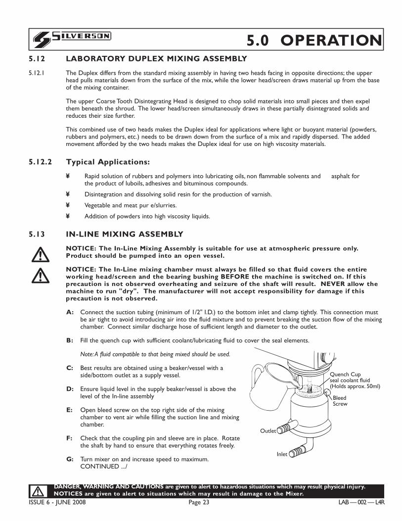
NOTICE: The In-Line Mixing Assembly is suitable for use at atmospheric pressure only.Product should be pumped into an open vessel.
NOTICE: The In-Line mixing chamber must always be filled so that fluid covers the entireworking head/screen and the bearing bushing BEFORE the machine is switched on. If thisprecaution is not observed overheating and seizure of the shaft will result. NEVER allow themachine to run "dry". The manufacturer will not accept responsibility for damage if thisprecaution is not observed.
A: Connect the suction tubing (minimum of 1/2" I.D.) to the bottom inlet and clamp tightly. This connection mustbe air tight to avoid introducing air into the fluid mixture and to prevent breaking the suction flow of the mixingchamber. Connect similar discharge hose of sufficient length and diameter to the outlet.
B: Fill the quench cup with sufficient coolant/lubricating fluid to cover the seal elements.
Note: A fluid compatible to that being mixed should be used.
C: Best results are obtained using a beaker/vessel with aside/bottom outlet as a supply vessel.
D: Ensure liquid level in the supply beaker/vessel is above thelevel of the In-line assembly
E: Open bleed screw on the top right side of the mixingchamber to vent air while filling the suction line and mixingchamber.
F: Check that the coupling pin and sleeve are in place. Rotatethe shaft by hand to ensure that everything rotates freely.
G: Turn mixer on and increase speed to maximum.CONTINUED .../
!!
C0135
Outlet
Inlet
BleedScrew
Quench Cupseal coolant fluid(Holds approx. 50ml)
Outlet
Inlet
Surub tubular
Cana de umplereCu lichid de racire(capacitate approx. 50ml)
ROM
LAB — 002 — L4R Page 24 ISSUE 6 - JUNE 2008
DANGER, WARNING AND CAUTIONS are given to alert to hazardous situations which may result physical injuryNOTICES are given to alert to situations which may result in damage to the Mixer.!
S5.0 OPERATIONIN-LINE MIXING ASSEMBLY Contd.../...
H: Ensure satisfactory circulation. You may want to install a flow control valve on the discharge side of the mixer tocontrol the rate of flow and processing.
NOTICE: Do not add a control valve to the the supply side.
I: Add additional ingredients either directly into the beaker/vessel or into the In-line mixer assembly inlet by meansof a laboratory pump.
Note: High viscosity materials can be mixed by using a laboratory pump to feed them into the In-line mixer assembly.
5.14 CLEANING
5.14.1 The L4R Mixer is in most cases self cleaning, a short run between successive mixing operations in water, detergent oran appropriate non-flammable solvent should be all that is necessary to clean the wetted parts. For more thoroughcleaning, dismantling is easy and downtime minimal.
5.14.2 The housing and wetted parts can be cleaned with household cleaning agents providing that they do not containsolvents and are non-scratching. Do not scour the parts with sharp objects.
!WARNING: IF IT IS NECESSARY TO USE FLAMMABLE SOLVENTS TO CLEAN MIXEDPRODUCT OFF THE WETTED PARTS, THEN THE MIXING ASSEMBLY MUST BE REMOVEDAND CLEANED IN A SAFE AREA, AWAY FROM THE MACHINE.!WARNING: THE MACHINE SHOULD NEVER BE SPRAYED WITH WATER OR IMMERSED INWATER.
5.15 CHANGING THE STATOR OF THE STANDARD MIXING ASSEMBLY
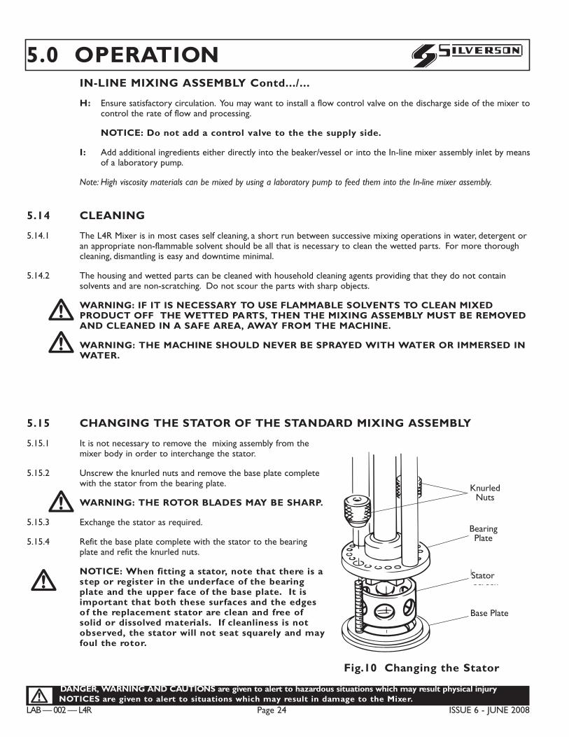
5.15.1 It is not necessary to remove the mixing assembly from themixer body in order to interchange the stator.
5.15.2 Unscrew the knurled nuts and remove the base plate completewith the stator from the bearing plate.!WARNING: THE ROTOR BLADES MAY BE SHARP.
5.15.3 Exchange the stator as required.
5.15.4 Refit the base plate complete with the stator to the bearingplate and refit the knurled nuts.
NOTICE: When fitting a stator, note that there is astep or register in the underface of the bearingplate and the upper face of the base plate. It isimportant that both these surfaces and the edgesof the replacement stator are clean and free ofsolid or dissolved materials. If cleanliness is notobserved, the stator will not seat squarely and mayfoul the rotor.
!
KnurledNuts
BearingPlate
Head orScreen
Base Plate
C0060
Piulite zimtat
Placa suport
Cap/filtru
Placa de baza
Fig.10 Changing the Stator
Stator
DANGER, WARNING AND CAUTIONS are given to alert to hazardous situations which may result physical injury.NOTICES are given to alert to situations which may result in damage to the Mixer.!
ISSUE 6 - JUNE 2008 Page 25 LAB — 002 — L4R
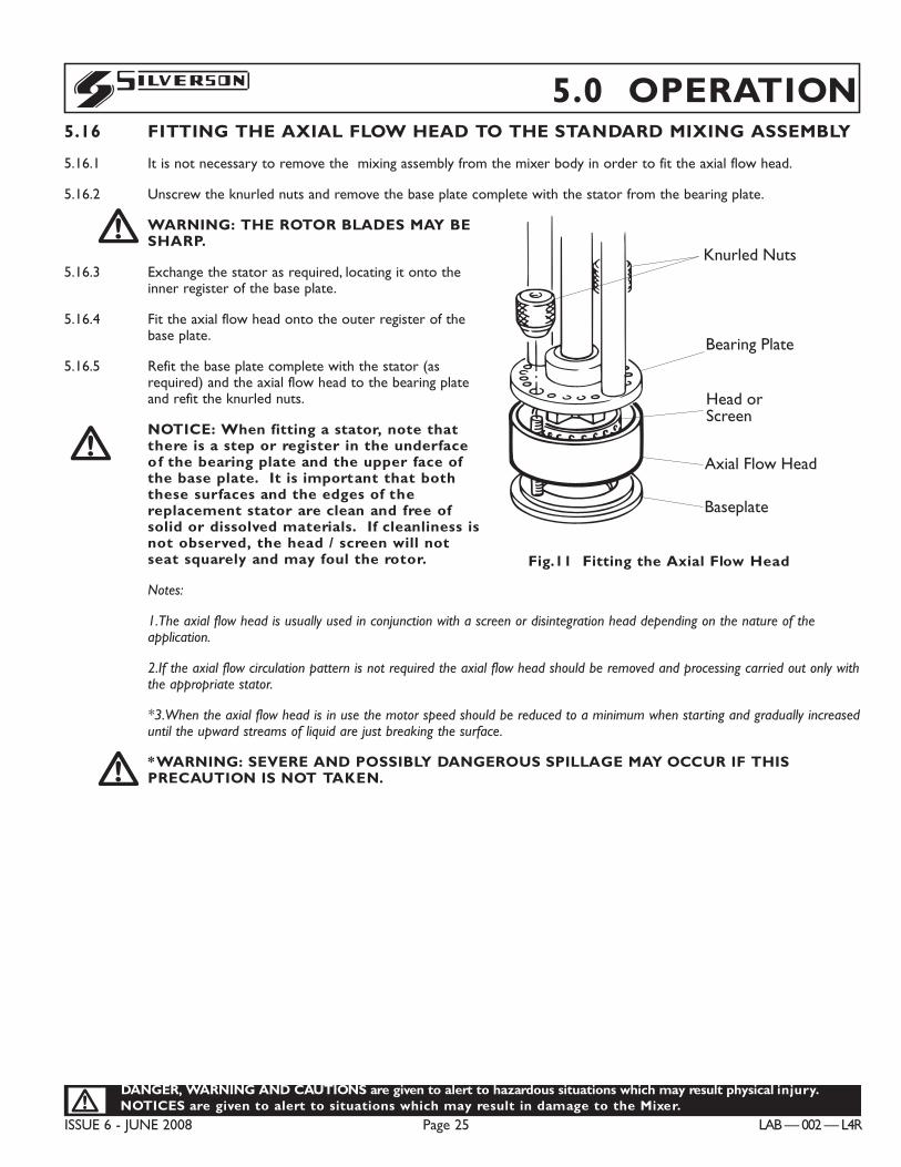
S 5.0 OPERATION5.16 FITTING THE AXIAL FLOW HEAD TO THE STANDARD MIXING ASSEMBLY
5.16.1 It is not necessary to remove the mixing assembly from the mixer body in order to fit the axial flow head.
5.16.2 Unscrew the knurled nuts and remove the base plate complete with the stator from the bearing plate.
!WARNING: THE ROTOR BLADES MAY BESHARP.
5.16.3 Exchange the stator as required, locating it onto theinner register of the base plate.
5.16.4 Fit the axial flow head onto the outer register of thebase plate.
5.16.5 Refit the base plate complete with the stator (asrequired) and the axial flow head to the bearing plateand refit the knurled nuts.
NOTICE: When fitting a stator, note thatthere is a step or register in the underfaceof the bearing plate and the upper face ofthe base plate. It is important that boththese surfaces and the edges of thereplacement stator are clean and free ofsolid or dissolved materials. If cleanliness isnot observed, the head / screen will notseat squarely and may foul the rotor.
Notes:
1.The axial flow head is usually used in conjunction with a screen or disintegration head depending on the nature of theapplication.
2.If the axial flow circulation pattern is not required the axial flow head should be removed and processing carried out only withthe appropriate stator.
*3.When the axial flow head is in use the motor speed should be reduced to a minimum when starting and gradually increaseduntil the upward streams of liquid are just breaking the surface.
!*WARNING: SEVERE AND POSSIBLY DANGEROUS SPILLAGE MAY OCCUR IF THISPRECAUTION IS NOT TAKEN.
!
Knurled Nuts
Bearing Plate
Head orScreen
Axial Flow Head
Baseplate
C0097
Piulite zimtate
Placa suport
Cap sau filtru
Cap de eruptie axial
Placa de baza
ROM
Fig.11 Fitting the Axial Flow Head
LAB — 002 — L4R Page 26 ISSUE 6 - JUNE 2008
DANGER, WARNING AND CAUTIONS are given to alert to hazardous situations which may result physical injuryNOTICES are given to alert to situations which may result in damage to the Mixer.!
S5.0 OPERATIONOPTIONAL ACCESSORIES:
5.17 CHANGING THE STATOR ON TUBULAR MIXING ASSEMBLIES
NOTE: Stators can only be interchanged on certain 1" and 3/4" Tubular frames.
5.17.1 It is not necessary to remove the frame from the mixer body in order to interchange the stator.
5.17.2 The stator is removed by unscrewing from the base of tubular frame.
NOTE:The tubular frames have a left hand thread (To remove head/screen rotate in a clockwise directionwhen viewed from below)!WARNING: THE ROTOR BLADES AND STATOR MAY BE SHARP.
5.17.3 An alternative or replacement stator is fitted by reversing the above procedure.
5.18 CHANGING THE STATOR ON THE LABORATORY DUPLEX MIXINGASSEMBLY
THE LOWER STATOR:
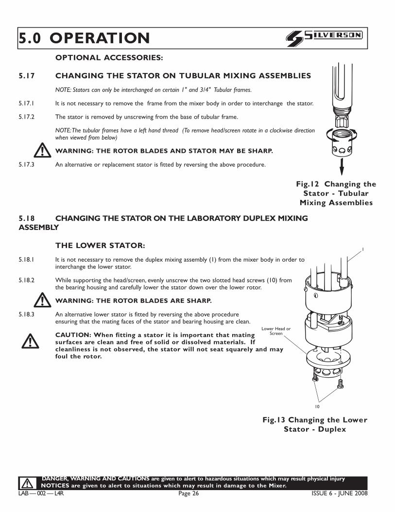
5.18.1 It is not necessary to remove the duplex mixing assembly (1) from the mixer body in order tointerchange the lower stator.
5.18.2 While supporting the head/screen, evenly unscrew the two slotted head screws (10) fromthe bearing housing and carefully lower the stator down over the lower rotor.!WARNING: THE ROTOR BLADES ARE SHARP.
5.18.3 An alternative lower stator is fitted by reversing the above procedureensuring that the mating faces of the stator and bearing housing are clean.
CAUTION: When fitting a stator it is important that matingsurfaces are clean and free of solid or dissolved materials. Ifcleanliness is not observed, the stator will not seat squarely and mayfoul the rotor.
!
KnurledNuts
BearingPlate
Head orScreen
Base Plate
C0060
Piulite zimtat
Placa suport
Cap/filtru
Placa de baza
Fig.12 Changing theStator - Tubular
Mixing Assemblies
10
Lower Head orScreen
1
C0094
10
Capul/FiltrulInferior
1
Fig.13 Changing the LowerStator - Duplex
DANGER, WARNING AND CAUTIONS are given to alert to hazardous situations which may result physical injury.NOTICES are given to alert to situations which may result in damage to the Mixer.!
ISSUE 6 - JUNE 2008 Page 27 LAB — 002 — L4R
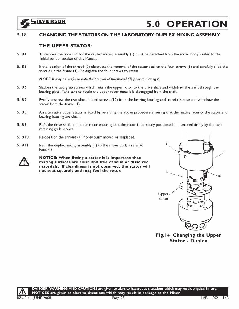
S 5.0 OPERATION5.18 CHANGING THE STATORS ON THE LABORATORY DUPLEX MIXING ASSEMBLY
THE UPPER STATOR:
5.18.4 To remove the upper stator the duplex mixing assembly (1) must be detached from the mixer body - refer to theÔinitial set upÕ section of this Manual.
5.18.5 If the location of the shroud (7) obstructs the removal of the stator slacken the four screws (9) and carefully slide theshroud up the frame (1). Re-tighten the four screws to retain.
NOTE: It may be useful to note the position of the shroud (7) prior to moving it.
5.18.6 Slacken the two grub screws which retain the upper rotor to the drive shaft and withdraw the shaft through thebearing plate. Take care to retain the upper rotor once it is disengaged from the shaft.
5.18.7 Evenly unscrew the two slotted head screws (10) from the bearing housing and carefully raise and withdraw thestator from the frame (1).
5.18.8 An alternative upper stator is fitted by reversing the above procedure ensuring that the mating faces of the stator andbearing housing are clean.
5.18.9 Refit the drive shaft and upper rotor ensuring that the rotor is correctly positioned and secured firmly by the tworetaining grub screws.
5.18.10 Re-position the shroud (7) if previously moved or displaced.
5.18.11 Refit the duplex mixing assembly (1) to the mixer body - refer toPara. 4.3
NOTICE: When fitting a stator it is important thatmating surfaces are clean and free of solid or dissolvedmaterials. If cleanliness is not observed, the stator willnot seat squarely and may foul the rotor.
!
Upper Head
9
7
10
1
C0093
Cap superior
9
7
10
1
Fig.14 Changing the UpperStator - Duplex
UpperStator
LAB — 002 — L4R Page 28 ISSUE 6 - JUNE 2008
DANGER, WARNING AND CAUTIONS are given to alert to hazardous situations which may result physical injuryNOTICES are given to alert to situations which may result in damage to the Mixer.!
S5.0 OPERATIONOPTIONAL ACCESSORIES -
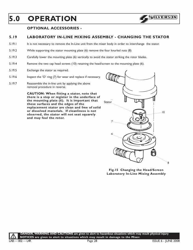
5.19 LABORATORY IN-LINE MIXING ASSEMBLY - CHANGING THE STATOR
5.19.1 It is not necessary to remove the In-Line unit from the mixer body in order to interchange the stator.
5.19.2 While supporting the stator mounting plate (6) remove the four knurled nuts (8)
5.19.3 Carefully lower the mounting plate (6) vertically to avoid the stator striking the rotor blades.
5.19.4 Remove the two cap head screws (10) retaining the head/screen to the mounting plate (6).
5.19.5 Exchange the stator as required.
5.19.6 Inspect the ’O’ ring (7) for wear and replace if necessary.
5.19.7 Reassemble the in-line unit by applying the aboveremoval procedure in reverse.
CAUTION: When fitting a stator, note thatthere is a step or register in the underface ofthe mounting plate (6). It is important thatthese surfaces and the edges of thereplacement stator are clean and free of solidor dissolved materials. If cleanliness is notobserved, the stator will not seat squarelyand may foul the rotor.
C0092
Head orScreen
7
6
10
8
capului/filtrului
7
6
10
8
Fig.15 Changing the Head/ScreenLaboratory In-Line Mixing Assembly
Stator
DANGER, WARNING AND CAUTIONS are given to alert to hazardous situations which may result physical injury.NOTICES are given to alert to situations which may result in damage to the Mixer.!
ISSUE 6 - JUNE 2008 Page 29 LAB — 002 — L4R
S 6.0 MAINTENANCE6.0 MAINTENANCE PROCEDURES
!WARNING: ALWAYS ISOLATE THE MACHINE FROM THE ELECTRICAL SUPPLY BEFOREPERFORMING MAINTENANCE PROCEDURES.
6.1 REPLACING THE BUSHING
All mixing assemblies have bushing (bronze alloy or PTFE). This bearing bushing is lubricated and cooled by theproduct being mixed. During operation the entire workhead/screen and bearing bushing must always be immersed inthe fluid being mixed. Failure to do so will result in rapid overheating and seizure of the shaft.
The bushing is a wearing part which needs to be replaced at periodic intervals depending on the characteristics of themix.
The bushing must be regularly inspected for signs of wear and replaced when necessary. Where there is anyperceptible movement of the shaft within the bushing, the bushing should be replaced.
CAUTION: Failure to replace the bushing when required will cause considerable damage tothe Mixer.
Note: Prior to carrying out the following instructions the mixing assembly must be disassembled and the drive shaft and rotorremoved; specific instructions for the disassembly of each of the mixing assembly are given in the following paragraphs. Turn themixing frame thro’ 180¡ so that the bearing plate is uppermost.
PTFE BUSHING
6.1.1 The PTFE bushing (3) is a press-fit and can be easily prised out or pushed into the bearing plate.
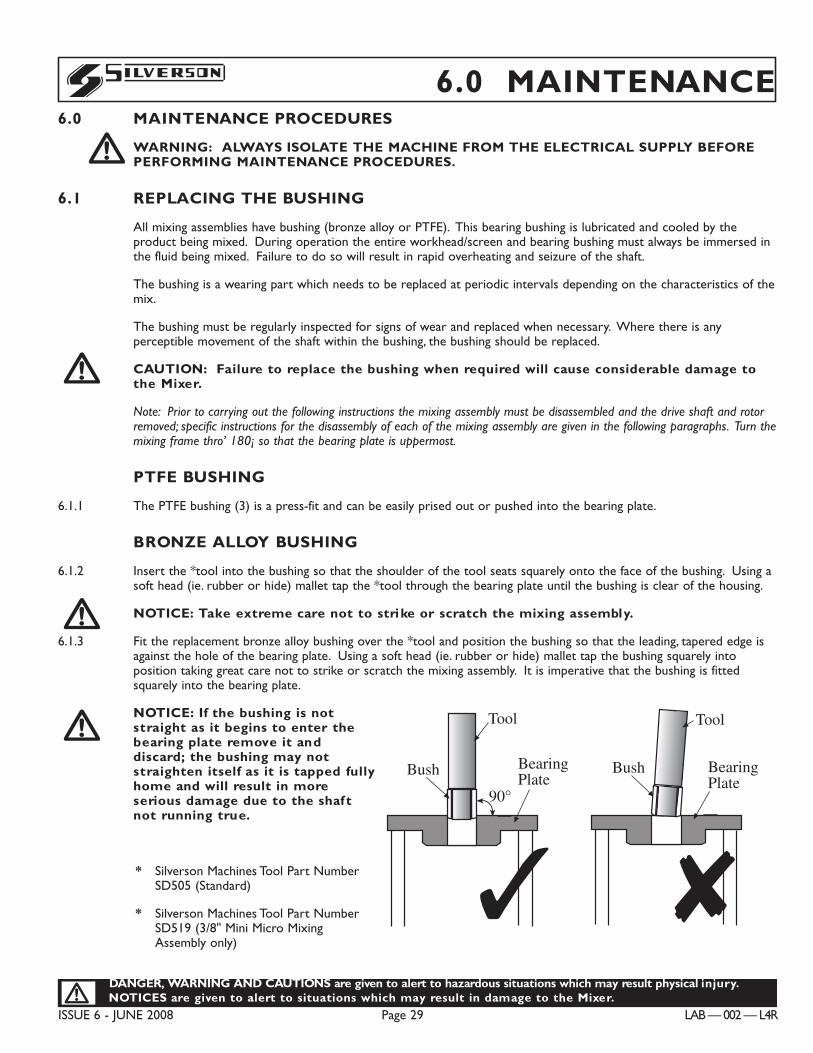
BRONZE ALLOY BUSHING
6.1.2 Insert the *tool into the bushing so that the shoulder of the tool seats squarely onto the face of the bushing. Using asoft head (ie. rubber or hide) mallet tap the *tool through the bearing plate until the bushing is clear of the housing.
NOTICE: Take extreme care not to strike or scratch the mixing assembly.
6.1.3 Fit the replacement bronze alloy bushing over the *tool and position the bushing so that the leading, tapered edge isagainst the hole of the bearing plate. Using a soft head (ie. rubber or hide) mallet tap the bushing squarely intoposition taking great care not to strike or scratch the mixing assembly. It is imperative that the bushing is fittedsquarely into the bearing plate.
NOTICE: If the bushing is notstraight as it begins to enter thebearing plate remove it anddiscard; the bushing may notstraighten itself as it is tapped fullyhome and will result in moreserious damage due to the shaf tnot running true.
* Silverson Machines Tool Part NumberSD505 (Standard)
* Silverson Machines Tool Part NumberSD519 (3/8" Mini Micro MixingAssembly only)
!
!
!
90°
Outil
Palier
Plaque delogement dupalier
Palier
Outil
8Plaque delogement dupalier
90°
Drift
Bush BearingPlate
3
Bush BearingPlate
Drift
8
3C0011
BearingPlate
90°
Tool
Bush
3 8
Bush BearingPlate
Tool
90°
Outil
Palier
Plaque delogement dupalier
Palier
Outil
8Plaque delogement dupalier
90°
Drift
Bush BearingPlate
3
Bush BearingPlate
Drift
8
3C0011
BearingPlate
90°
Tool
Bush
3 8
Bush BearingPlate
Tool
LAB — 002 — L4R Page 30 ISSUE 6 - JUNE 2008
DANGER, WARNING AND CAUTIONS are given to alert to hazardous situations which may result physical injuryNOTICES are given to alert to situations which may result in damage to the Mixer.!
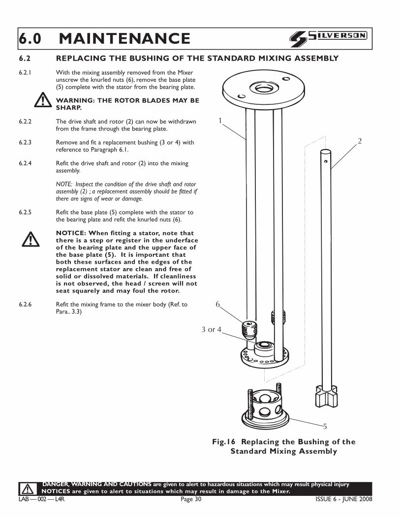
S6.0 MAINTENANCE6.2 REPLACING THE BUSHING OF THE STANDARD MIXING ASSEMBLY
6.2.1 With the mixing assembly removed from the Mixerunscrew the knurled nuts (6), remove the base plate(5) complete with the stator from the bearing plate.!WARNING: THE ROTOR BLADES MAY BESHARP.
6.2.2 The drive shaft and rotor (2) can now be withdrawnfrom the frame through the bearing plate.
6.2.3 Remove and fit a replacement bushing (3 or 4) withreference to Paragraph 6.1.
6.2.4 Refit the drive shaft and rotor (2) into the mixingassembly.
NOTE: Inspect the condition of the drive shaft and rotorassembly (2) ; a replacement assembly should be fitted ifthere are signs of wear or damage.
6.2.5 Refit the base plate (5) complete with the stator tothe bearing plate and refit the knurled nuts (6).
NOTICE: When fitting a stator, note thatthere is a step or register in the underfaceof the bearing plate and the upper face ofthe base plate (5). It is important thatboth these surfaces and the edges of thereplacement stator are clean and free ofsolid or dissolved materials. If cleanlinessis not observed, the head / screen will notseat squarely and may foul the rotor.
6.2.6 Refit the mixing frame to the mixer body (Ref. toPara.. 3.3)
!
5
6
3 or 4
2
C0101
1
Fig.16 Replacing the Bushing of theStandard Mixing Assembly
DANGER, WARNING AND CAUTIONS are given to alert to hazardous situations which may result physical injury.NOTICES are given to alert to situations which may result in damage to the Mixer.!
ISSUE 6 - JUNE 2008 Page 31 LAB — 002 — L4R
S
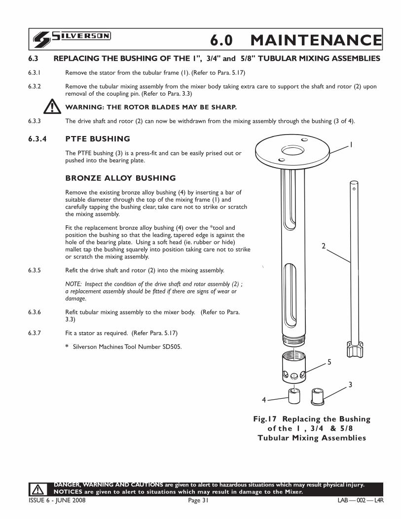
6.3 REPLACING THE BUSHING OF THE 1", 3/4" and 5/8" TUBULAR MIXING ASSEMBLIES
6.3.1 Remove the stator from the tubular frame (1). (Refer to Para. 5.17)
6.3.2 Remove the tubular mixing assembly from the mixer body taking extra care to support the shaft and rotor (2) uponremoval of the coupling pin. (Refer to Para. 3.3)!WARNING: THE ROTOR BLADES MAY BE SHARP.
6.3.3 The drive shaft and rotor (2) can now be withdrawn from the mixing assembly through the bushing (3 of 4).
6.3.4 PTFE BUSHING
The PTFE bushing (3) is a press-fit and can be easily prised out orpushed into the bearing plate.
BRONZE ALLOY BUSHING
Remove the existing bronze alloy bushing (4) by inserting a bar ofsuitable diameter through the top of the mixing frame (1) andcarefully tapping the bushing clear, take care not to strike or scratchthe mixing assembly.
Fit the replacement bronze alloy bushing (4) over the *tool andposition the bushing so that the leading, tapered edge is against thehole of the bearing plate. Using a soft head (ie. rubber or hide)mallet tap the bushing squarely into position taking care not to strikeor scratch the mixing assembly.
6.3.5 Refit the drive shaft and rotor (2) into the mixing assembly.
NOTE: Inspect the condition of the drive shaft and rotor assembly (2) ;a replacement assembly should be fitted if there are signs of wear ordamage.
6.3.6 Refit tubular mixing assembly to the mixer body. (Refer to Para.3.3)
6.3.7 Fit a stator as required. (Refer Para. 5.17)
* Silverson Machines Tool Number SD505.
6.0 MAINTENANCE
Fig.17 Replacing the Bushingof the 1Ó , 3/4Ó & 5/8Ó
Tubular Mixing Assemblies
C0055
2
1
5
3
4

LAB — 002 — L4R Page 32 ISSUE 6 - JUNE 2008
DANGER, WARNING AND CAUTIONS are given to alert to hazardous situations which may result physical injuryNOTICES are given to alert to situations which may result in damage to the Mixer.!
S6.0 MAINTENANCE6.4 REPLACING THE BUSHING OF THE 3/8" MINI-MICRO TUBULAR MIXING ASSEMBLY
6.4.1 Remove the tubular mixing assembly from the mixer body. (Refer to Para. 3.3)
6.4.2 With the rotor removal rod* insertedthrough the hole in the top of the driveshaft (2) locate the rotor removal tool*over the blades of the rotor (4). Using therod* as a locking bar against the sides ofthe frame apertures, rotate the tool* tounscrew the rotor from the shaft. Onceseparated, the rotor (4) can be removedfrom the bottom of the tubular frame.
The shaft (2) is then withdrawn throughthe top of the frame.!WARNING: THE ROTOR BLADESMAY BE SHARP.
6.4.3 PTFE BUSHING
The PTFE bushing (3) is a push-fit and canbe easily prised out or pushed into thebearing plate.
6.4.4 Refit the drive shaft and rotor (2) into themixing assembly.
NOTE: Inspect the condition of the driveshaft and rotor assembly (2) ; a replacementassembly should be fitted if there are signs ofwear or damage.
6.4.5 Refit tubular mixing assembly to the mixerbody. (Refer to Para. 3.3)
**The rotor removal rod and toolare supplied with the tubularframe.
2
1
Rotor RemovalRod
3
4
Rotor RemovalTool
C0100
Fig.18 Replacing the Bushing of the 3/8Ó Mini-Micro Tubular Mixing Assembly
DANGER, WARNING AND CAUTIONS are given to alert to hazardous situations which may result physical injury.NOTICES are given to alert to situations which may result in damage to the Mixer.!
ISSUE 6 - JUNE 2008 Page 33 LAB — 002 — L4R
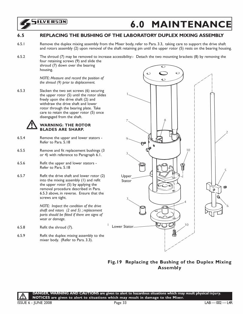
S 6.0 MAINTENANCE6.5 REPLACING THE BUSHING OF THE LABORATORY DUPLEX MIXING ASSEMBLY
6.5.1 Remove the duplex mixing assembly from the Mixer body, refer to Para. 3.3, taking care to support the drive shaftand rotors assembly (2) upon removal of the shaft retaining pin until the upper rotor (5) rests on the bearing housing.
6.5.2 The shroud (7) may be removed to increase accessibility:- Detach the two mounting brackets (8) by removing thefour retaining screws (9) and slide theshroud (7) down over the bearinghousing.
NOTE: Measure and record the position ofthe shroud (9) prior to displacement.
6.5.3 Slacken the two set screws (6) securingthe upper rotor (5) until the rotor slidesfreely upon the drive shaft (2) andwithdraw the drive shaft and lowerrotor through the bearing plate. Takecare to retain the upper rotor (5) oncedisengaged from the shaft.!WARNING: THE ROTORBLADES ARE SHARP.
6.5.4 Remove the upper and lower stators -Refer to Para. 5.18
6.5.5 Remove and fit replacement bushings (3or 4) with reference to Paragraph 6.1.
6.5.6 Refit the upper and lower stators -Refer to Para. 5.18
6.5.7 Refit the drive shaft and lower rotor (2)into the mixing assembly (1) and refitthe upper rotor (5) by applying theremoval procedure described in Para.6.5.3 above, in reverse. Ensure that thescrews are tight.
NOTE: Inspect the condition of the driveshaft and rotors (2 and 5) ; replacementparts should be fitted if there are signs ofwear or damage.
6.5.8 Refit the shroud (7).
6.5.9 Refit the duplex mixing assembly to themixer body. (Refer to Para. 3.3).
1
7 8
9
3
UpperWorkhead
34
Lower Workheador Screen
10
10
5
6
2
C0099Fig.19 Replacing the Bushing of the Duplex MixingAssembly
UpperStator
Lower Stator
LAB — 002 — L4R Page 34 ISSUE 6 - JUNE 2008
DANGER, WARNING AND CAUTIONS are given to alert to hazardous situations which may result physical injuryNOTICES are given to alert to situations which may result in damage to the Mixer.!
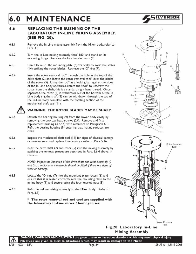
S6.0 MAINTENANCE6.6 REPLACING THE BUSHING OF THE
LABORATORY IN-LINE MIXING ASSEMBLY.(SEE FIG. 20).
6.6.1 Remove the In-Line mixing assembly from the Mixer body, refer toPara. 3.3
6.6.2 Turn the In-Line mixing assembly thro’ 180¡ and stand on itsmounting flange. Remove the four knurled nuts (8).
6.6.3 Carefully raise the mounting plate (6) vertically to avoid the stator(14) striking the rotor blades. Retrieve the ’O’ ring (7).
6.6.4 Insert the rotor removal rod* through the hole in the top of thedrive shaft (2) and locate the rotor removal tool* over the bladesof the rotor (5). Using the rod* as a locking bar against the sidesof the In-Line body apertures, rotate the tool* to unscrew therotor from the shaft; this is a standard right hand thread. Onceseparated, the rotor (5) is withdrawn out of the bottom of the In-Line body (1), the shaft (2) can be withdrawn through the top ofthe In-Line body complete with the rotating section of themechanical shaft seal (11).!WARNING: THE ROTOR BLADES MAY BE SHARP.
6.6.5 Detach the bearing housing (9) from the lower body cavity byremoving the two cap head screws (24). Remove and fit areplacement bushing (3 or 4) with reference to Paragraph 6.1.Refit the bearing housing (9) ensuring that mating surfaces areclean.
6.6.6 Inspect the mechanical shaft seal (11) for signs of physical damageor uneven wear and replace if necessary - refer to Para. 5.26
6.6.7 Refit the drive shaft (2) and rotor (5) into the mixing assembly byapplying the removal procedure described in Para. 6.6.4 above, inreverse.
NOTE: Inspect the condition of the drive shaft and rotor assembly (2and 5) ; a replacement assembly should be fitted if there are signs ofwear or damage.
6.6.8 Locate the ’O’ ring (7) into the mounting plate recess (6) andensure that it is seated correctly, refit the mounting plate to thein-line body (1) and secure using the four knurled nuts (8).
6.6.9 Refit the In-Line mixing assembly to the Mixer body. (Refer toPara. 3.3)
* The rotor removal rod and tool are supplied withthe laboratory In-Line mixer / homogeniser.
Rotor RemovalRod
11
Rotor RemovalTool
C0104
11
1
1312
21
924
3 or 4
10
147
21
6
8
23
22
C0090
2
11
5
Fig.20 Laboratory In-Line Mixing Assembly
DANGER, WARNING AND CAUTIONS are given to alert to hazardous situations which may result physical injury.NOTICES are given to alert to situations which may result in damage to the Mixer.!
ISSUE 6 - JUNE 2008 Page 35 LAB — 002 — L4R
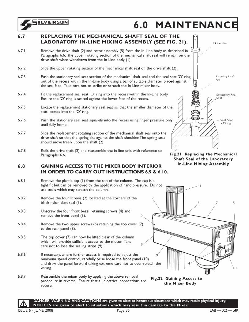
S 6.0 MAINTENANCE6.7 REPLACING THE MECHANICAL SHAFT SEAL OF THE
LABORATORY IN-LINE MIXING ASSEMBLY (SEE FIG. 21).
6.7.1 Remove the drive shaft (2) and rotor assembly (5) from the In-Line body as described inParagraphs 6.6; the upper rotating section of the mechanical shaft seal will remain on thedrive shaft when withdrawn from the In-Line body (1).
6.7.2 Slide the upper rotating section of the mechanical shaft seal off the drive shaft (2).
6.7.3 Push the stationary seal seat section of the mechanical shaft seal and the seal seat ’O’ ringout of the recess within the In-Line body using a bar of suitable diameter placed againstthe seal face. Take care not to strike or scratch the In-Line mixer body.
6.7.4 Fit the replacement seal seat ’O’ ring into the recess within the In-Line body.Ensure the ’O’ ring is seated against the lower face of the recess.
6.7.5 Locate the replacement stationary seal seat so that the smaller diameter of theseat locates into the ’O’ ring.
6.7.6 Push the stationary seal seat squarely into the recess using finger pressure onlyuntil fully home.
6.7.7 Slide the replacement rotating section of the mechanical shaft seal onto thedrive shaft so that the spring sits against the shaft shoulder.The spring seatshould move freely upon the shaft (2) .
6.7.8 Refit the drive shaft (2) and reassemble the in-line unit with reference toParagraphs 6.6.
6.8 GAINING ACCESS TO THE MIXER BODY INTERIOR IN ORDER TO CARRY OUT INSTRUCTIONS 6.9 & 6.10.
6.8.1 Remove the plastic cap (1) from the top of the column. The cap is atight fit but can be removed by the application of hand pressure. Do notuse tools which may scratch the column.
6.8.2 Remove the four screws (2) located at the corners of theblack nylon dust seal (3).
6.8.3 Unscrew the four front bezel retaining screws (4) andremove the front bezel (5).
6.8.4 Remove the two upper screws (6) retaining the top cover (7)to the rear panel (8).
6.8.5 The top cover (7) can now be lifted clear of the columnwhich will provide sufficient access to the motor. Takecare not to lose the sealing strips (9).
6.8.6 If necessary, where further access is required to adjust theminimum speed control, carefully prise loose the front panel (10)and draw the panel forward taking extreme care not to over-stretch thewiring.
6.8.7 Reassemble the mixer body by applying the above removalprocedure in reverse. Ensure that all electrical connections aresecure.
Rotating ShaftSeal
Stationary SealSeat
Seal Seat‘O’Ring
C0096
Drive Shaft
Fig.21 Replacing the MechanicalShaft Seal of the Laboratory
In-Line Mixing Assembly
Fig.22 Gaining Access tothe Mixer Body
2
6
8
9
4
1
3 7 5
10
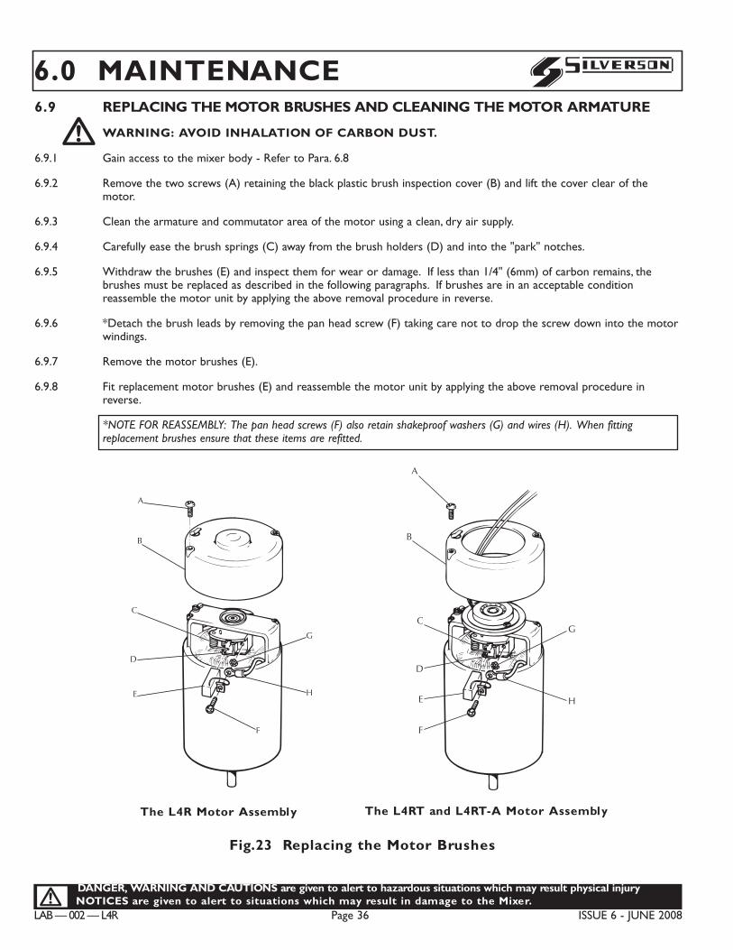
LAB — 002 — L4R Page 36 ISSUE 6 - JUNE 2008
DANGER, WARNING AND CAUTIONS are given to alert to hazardous situations which may result physical injuryNOTICES are given to alert to situations which may result in damage to the Mixer.!
S6.0 MAINTENANCE6.9 REPLACING THE MOTOR BRUSHES AND CLEANING THE MOTOR ARMATURE!WARNING: AVOID INHALATION OF CARBON DUST.
6.9.1 Gain access to the mixer body - Refer to Para. 6.8
6.9.2 Remove the two screws (A) retaining the black plastic brush inspection cover (B) and lift the cover clear of themotor.
6.9.3 Clean the armature and commutator area of the motor using a clean, dry air supply.
6.9.4 Carefully ease the brush springs (C) away from the brush holders (D) and into the "park" notches.
6.9.5 Withdraw the brushes (E) and inspect them for wear or damage. If less than 1/4" (6mm) of carbon remains, thebrushes must be replaced as described in the following paragraphs. If brushes are in an acceptable conditionreassemble the motor unit by applying the above removal procedure in reverse.
6.9.6 *Detach the brush leads by removing the pan head screw (F) taking care not to drop the screw down into the motorwindings.
6.9.7 Remove the motor brushes (E).
6.9.8 Fit replacement motor brushes (E) and reassemble the motor unit by applying the above removal procedure inreverse.
*NOTE FOR REASSEMBLY: The pan head screws (F) also retain shakeproof washers (G) and wires (H). When fittingreplacement brushes ensure that these items are refitted.
C0067
A
B
F
H
G
C
D
E
A
B
C
D
E
F
H
G
C0105
The L4R Motor Assembly The L4RT and L4RT-A Motor Assembly
Fig.23 Replacing the Motor Brushes
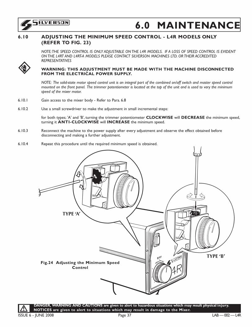
DANGER, WARNING AND CAUTIONS are given to alert to hazardous situations which may result physical injury.NOTICES are given to alert to situations which may result in damage to the Mixer.!
ISSUE 6 - JUNE 2008 Page 37 LAB — 002 — L4R
S 6.0 MAINTENANCE6.10 ADJUSTING THE MINIMUM SPEED CONTROL - L4R MODELS ONLY
(REFER TO FIG. 23)
NOTE:THE SPEED CONTROL IS ONLY ADJUSTABLE ON THE L4R MODELS. IF A LOSS OF SPEED CONTROL IS EVIDENTON THE L4RT AND L4RT-A MODELS PLEASE CONTACT SILVERSON MACHINES LTD. OR THEIR ACCREDITEDREPRESENTATIVES
WARNING: THIS ADJUSTMENT MUST BE MADE WITH THE MACHINE DISCONNECTEDFROM THE ELECTRICAL POWER SUPPLY.
NOTE: The solid-state motor speed control unit is an integral part of the combined on/off switch and master speed controlmounted on the front panel. The trimmer potentiometer is located at the top of the unit and is used to vary the minimumspeed of the mixer motor.
6.10.1 Gain access to the mixer body - Refer to Para. 6.8
6.10.2 Use a small screwdriver to make the adjustment in small incremental steps:
for both types; ’A’ and ’B’, turning the trimmer potentiometer CLOCKWISE will DECREASE the minimum speed,turning it ANTI-CLOCKWISE will INCREASE the minimum speed.
6.10.3 Reconnect the machine to the power supply after every adjustment and observe the effect obtained beforedisconnecting and making a further adjustment.
6.10.4 Repeat this procedure until the required minimum speed is obtained.
E
C0285
TYPE ‘A’
TYPE ‘B’Fig.24 Adjusting the Minimum Speed
Control
LAB — 002 — L4R Page 38 ISSUE 6 - JUNE 2008
DANGER, WARNING AND CAUTIONS are given to alert to hazardous situations which may result physical injuryNOTICES are given to alert to situations which may result in damage to the Mixer.!
S6.0 MAINTENANCE6.11 REPLACING THE FUSE
6.11.1 The fuse holder is located on the rear panel of the mixer body and is readily accessible without removing the panel.
6.11.2 Use a screwdriver to unscrew the fuse carrier from the holder.
6.11.3 Remove and fit a replacement fuse into the carrier. (Refer to Technical Specification for correct Ampere rating).
6.11.4 Refit the fuse carrier.
NOTICE: Ensure that the new fuse is of the correct rating (6.3 amp). If the fuse blowsrepeatedly, consult Silverson Machines Inc. or their accredited agent.!
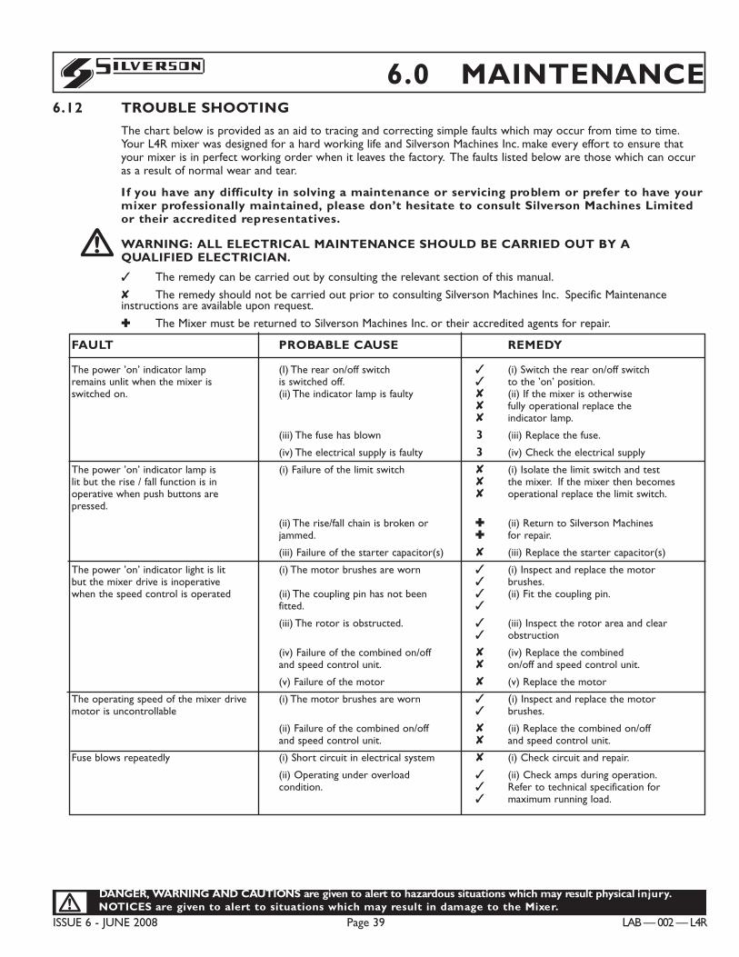
DANGER, WARNING AND CAUTIONS are given to alert to hazardous situations which may result physical injury.NOTICES are given to alert to situations which may result in damage to the Mixer.!
ISSUE 6 - JUNE 2008 Page 39 LAB — 002 — L4R
S 6.0 MAINTENANCE6.12 TROUBLE SHOOTING
The chart below is provided as an aid to tracing and correcting simple faults which may occur from time to time.Your L4R mixer was designed for a hard working life and Silverson Machines Inc. make every effort to ensure thatyour mixer is in perfect working order when it leaves the factory. The faults listed below are those which can occuras a result of normal wear and tear.
I f you have any difficulty in solving a maintenance or servicing problem or prefer to have yourmixer professionally maintained, please don’t hesitate to consult Silverson Machines Limitedor their accredited representatives.!WARNING: ALL ELECTRICAL MAINTENANCE SHOULD BE CARRIED OUT BY AQUALIFIED ELECTRICIAN.
3 The remedy can be carried out by consulting the relevant section of this manual.
8 The remedy should not be carried out prior to consulting Silverson Machines Inc. Specific Maintenance instructions are available upon request.
: The Mixer must be returned to Silverson Machines Inc. or their accredited agents for repair.
FAULT PROBABLE CAUSE REMEDY
The power ’on’ indicator lamp (I) The rear on/off switch 3 (i) Switch the rear on/off switch remains unlit when the mixer is is switched off. 3 to the ’on’ position.switched on. (ii) The indicator lamp is faulty 8 (ii) If the mixer is otherwise
8 fully operational replace the 8 indicator lamp.
(iii) The fuse has blown 3 (iii) Replace the fuse.
(iv) The electrical supply is faulty 3 (iv) Check the electrical supply
The power ’on’ indicator lamp is (i) Failure of the limit switch 8 (i) Isolate the limit switch and testlit but the rise / fall function is in 8 the mixer. If the mixer then becomesoperative when push buttons are 8 operational replace the limit switch.pressed.
(ii) The rise/fall chain is broken or : (ii) Return to Silverson Machinesjammed. : for repair.
(iii) Failure of the starter capacitor(s) 8 (iii) Replace the starter capacitor(s)
The power ’on’ indicator light is lit (i) The motor brushes are worn 3 (i) Inspect and replace the motor but the mixer drive is inoperative 3 brushes.when the speed control is operated (ii) The coupling pin has not been 3 (ii) Fit the coupling pin.
fitted. 3
(iii) The rotor is obstructed. 3 (iii) Inspect the rotor area and clear 3 obstruction
(iv) Failure of the combined on/off 8 (iv) Replace the combined and speed control unit. 8 on/off and speed control unit.
(v) Failure of the motor 8 (v) Replace the motor
The operating speed of the mixer drive (i) The motor brushes are worn 3 (i) Inspect and replace the motor motor is uncontrollable 3 brushes.
(ii) Failure of the combined on/off 8 (ii) Replace the combined on/off and speed control unit. 8 and speed control unit.
Fuse blows repeatedly (i) Short circuit in electrical system 8 (i) Check circuit and repair.
(ii) Operating under overload 3 (ii) Check amps during operation.condition. 3 Refer to technical specification for
3 maximum running load.
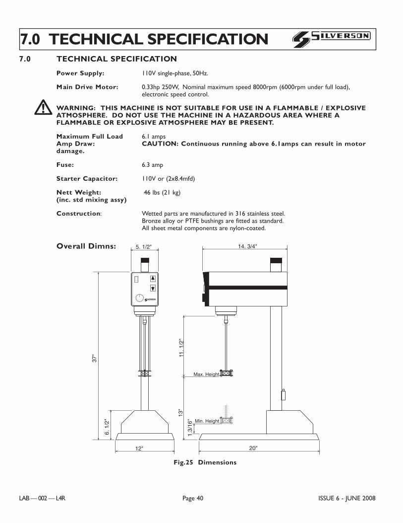
7.0 TECHNICAL SPECIFICATION
Power Supply: 110V single-phase, 50Hz.
Main Drive Motor: 0.33hp 250W, Nominal maximum speed 8000rpm (6000rpm under full load),electronic speed control.!WARNING: THIS MACHINE IS NOT SUITABLE FOR USE IN A FLAMMABLE / EXPLOSIVE
ATMOSPHERE. DO NOT USE THE MACHINE IN A HAZARDOUS AREA WHERE AFLAMMABLE OR EXPLOSIVE ATMOSPHERE MAY BE PRESENT.
Maximum Full Load 6.1 amps Amp Draw: CAUTION: Continuous running above 6.1amps can result in motordamage.
Fuse: 6.3 amp
Starter Capacitor: 110V or (2x8.4mfd)
Nett Weight: 46 lbs (21 kg)(inc. std mixing assy)
Construction: Wetted parts are manufactured in 316 stainless steel.Bronze alloy or PTFE bushings are fitted as standard.All sheet metal components are nylon-coated.
Overall Dimns:
7.0 TECHNICAL SPECIFICATION
LAB — 002 — L4R Page 40 ISSUE 6 - JUNE 2008
S
Fig.25 Dimensions
14. 3/4"5. 1/2"
37"
6. 1
/2"
12" 20"
11. 1
/2"
13"
1.3/
16"
Max. Height
Min. Height
C0020
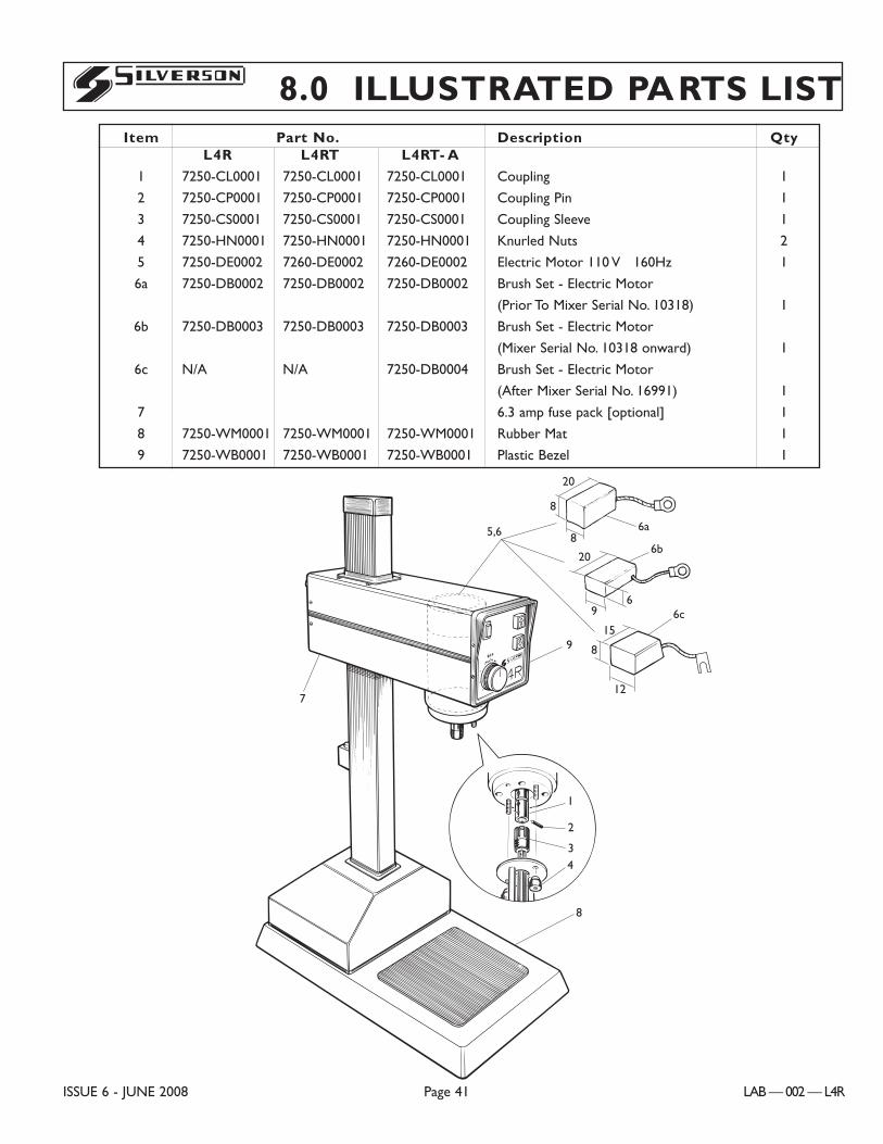
8.0 ILLUSTRATED PARTS LIST
ISSUE 6 - JUNE 2008 Page 41 LAB — 002 — L4R
S
Item Part No. Description QtyL4R L4RT L4RT- A
1 7250-CL0001 7250-CL0001 7250-CL0001 Coupling 1
2 7250-CP0001 7250-CP0001 7250-CP0001 Coupling Pin 1
3 7250-CS0001 7250-CS0001 7250-CS0001 Coupling Sleeve 1
4 7250-HN0001 7250-HN0001 7250-HN0001 Knurled Nuts 2
5 7250-DE0002 7260-DE0002 7260-DE0002 Electric Motor 110 V 160Hz 1
6a 7250-DB0002 7250-DB0002 7250-DB0002 Brush Set - Electric Motor
(Prior To Mixer Serial No. 10318) 1
6b 7250-DB0003 7250-DB0003 7250-DB0003 Brush Set - Electric Motor
(Mixer Serial No. 10318 onward) 1
6c N/A N/A 7250-DB0004 Brush Set - Electric Motor
(After Mixer Serial No. 16991) 1
7 6.3 amp fuse pack [optional] 1
8 7250-WM0001 7250-WM0001 7250-WM0001 Rubber Mat 1
9 7250-WB0001 7250-WB0001 7250-WB0001 Plastic Bezel 1
8
43
2
1
9
7
20
8
8
69
20
5,6 6a
6b
C0064
6c
8
15
12
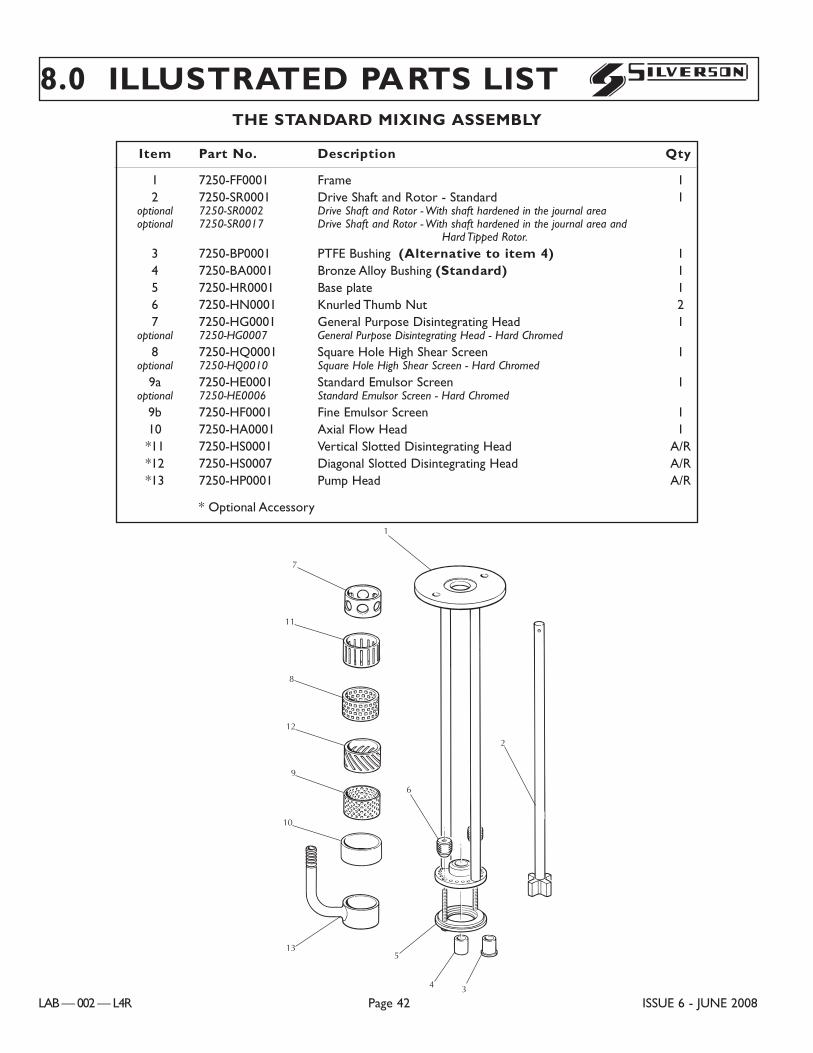
8.0 ILLUSTRATED PARTS LIST
LAB — 002 — L4R Page 42 ISSUE 6 - JUNE 2008
S
Item Part No. Description Qty
1 7250-FF0001 Frame 12 7250-SR0001 Drive Shaft and Rotor - Standard 1
optional 7250-SR0002 Drive Shaft and Rotor - With shaft hardened in the journal areaoptional 7250-SR0017 Drive Shaft and Rotor - With shaft hardened in the journal area and
Hard Tipped Rotor.
3 7250-BP0001 PTFE Bushing (Alternative to item 4) 14 7250-BA0001 Bronze Alloy Bushing (Standard) 15 7250-HR0001 Base plate 16 7250-HN0001 Knurled Thumb Nut 27 7250-HG0001 General Purpose Disintegrating Head 1
optional 7250-HG0007 General Purpose Disintegrating Head - Hard Chromed
8 7250-HQ0001 Square Hole High Shear Screen 1optional 7250-HQ0010 Square Hole High Shear Screen - Hard Chromed
9a 7250-HE0001 Standard Emulsor Screen 1optional 7250-HE0006 Standard Emulsor Screen - Hard Chromed
9b 7250-HF0001 Fine Emulsor Screen 110 7250-HA0001 Axial Flow Head 1*11 7250-HS0001 Vertical Slotted Disintegrating Head A/R*12 7250-HS0007 Diagonal Slotted Disintegrating Head A/R*13 7250-HP0001 Pump Head A/R
* Optional Accessory
13
9
6
5
4 3
2
1
C0089
7
10
11
12
8
THE STANDARD MIXING ASSEMBLY
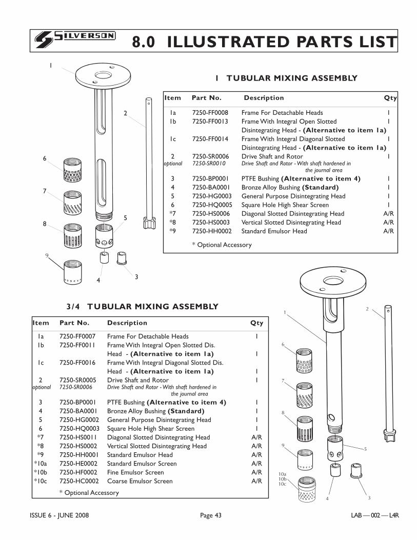
8.0 ILLUSTRATED PARTS LIST
ISSUE 6 - JUNE 2008 Page 43 LAB — 002 — L4R
S
Item Part No. Description Qty
1a 7250-FF0008 Frame For Detachable Heads 11b 7250-FF0013 Frame With Integral Open Slotted 1
Disintegrating Head - (Alternative to item 1a)1c 7250-FF0014 Frame With Integral Diagonal Slotted 1
Disintegrating Head - (Alternative to item 1a)2 7250-SR0006 Drive Shaft and Rotor 1
optional 7250-SR0010 Drive Shaft and Rotor - With shaft hardened in the journal area
3 7250-BP0001 PTFE Bushing (Alternative to item 4) 14 7250-BA0001 Bronze Alloy Bushing (Standard) 15 7250-HG0003 General Purpose Disintegrating Head 16 7250-HQ0005 Square Hole High Shear Screen 1*7 7250-HS0006 Diagonal Slotted Disintegrating Head A/R*8 7250-HS0003 Vertical Slotted Disintegrating Head A/R*9 7250-HH0002 Standard Emulsor Head A/R
* Optional Accessory
1
6
7
8
9
4 3
5
2
C0088
10a10b10c
1Ó TUBULAR MIXING ASSEMBLY
Item Part No. Description Qty
1a 7250-FF0007 Frame For Detachable Heads 11b 7250-FF0011 Frame With Integral Open Slotted Dis.
Head - (Alternative to item 1a) 11c 7250-FF0016 Frame With Integral Diagonal Slotted Dis.
Head - (Alternative to item 1a) 12 7250-SR0005 Drive Shaft and Rotor 1
optional 7250-SR0006 Drive Shaft and Rotor - With shaft hardened in the journal area
3 7250-BP0001 PTFE Bushing (Alternative to item 4) 14 7250-BA0001 Bronze Alloy Bushing (Standard) 15 7250-HG0002 General Purpose Disintegrating Head 16 7250-HQ0003 Square Hole High Shear Screen 1*7 7250-HS0011 Diagonal Slotted Disintegrating Head A/R*8 7250-HS0002 Vertical Slotted Disintegrating Head A/R*9 7250-HH0001 Standard Emulsor Head A/R
*10a 7250-HE0002 Standard Emulsor Screen A/R*10b 7250-HF0002 Fine Emulsor Screen A/R*10c 7250-HC0002 Coarse Emulsor Screen A/R
* Optional Accessory
3/4Ó TUBULAR MIXING ASSEMBLY
C0055
1
6
7
8
9
4 3
5
2
C0088
10a10b10c
6
7
8
1
2
5
4 3
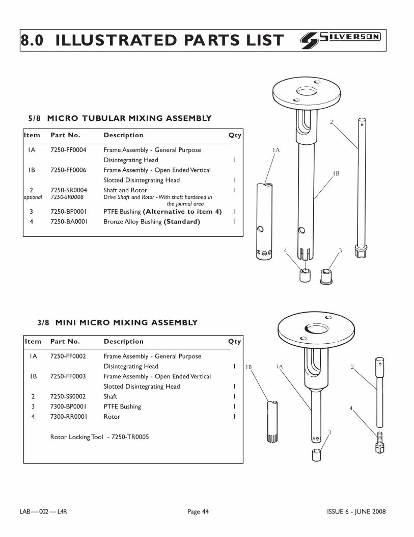
8.0 ILLUSTRATED PARTS LIST
LAB — 002 — L4R Page 44 ISSUE 6 - JUNE 2008
S
Item Part No. Description Qty
1A 7250-FF0002 Frame Assembly - General Purpose
Disintegrating Head 1
1B 7250-FF0003 Frame Assembly - Open Ended Vertical
Slotted Disintegrating Head 1
2 7250-SS0002 Shaft 1
3 7300-BP0001 PTFE Bushing 1
4 7300-RR0001 Rotor 1
Rotor Locking Tool - 7250-TR0005
1B 1A 2
3
4
C0106
3/8Ó MINI MICRO MIXING ASSEMBLY
Item Part No. Description Qty
1A 7250-FF0004 Frame Assembly - General Purpose
Disintegrating Head 1
1B 7250-FF0006 Frame Assembly - Open Ended Vertical
Slotted Disintegrating Head 1
2 7250-SR0004 Shaft and Rotor 1optional 7250-SR0008 Drive Shaft and Rotor - With shaft hardened in
the journal area3 7250-BP0001 PTFE Bushing (Alternative to item 4) 1
4 7250-BA0001 Bronze Alloy Bushing (Standard) 1
2
1B
1A
4 3
C0087
5/8Ó MICRO TUBULAR MIXING ASSEMBLY
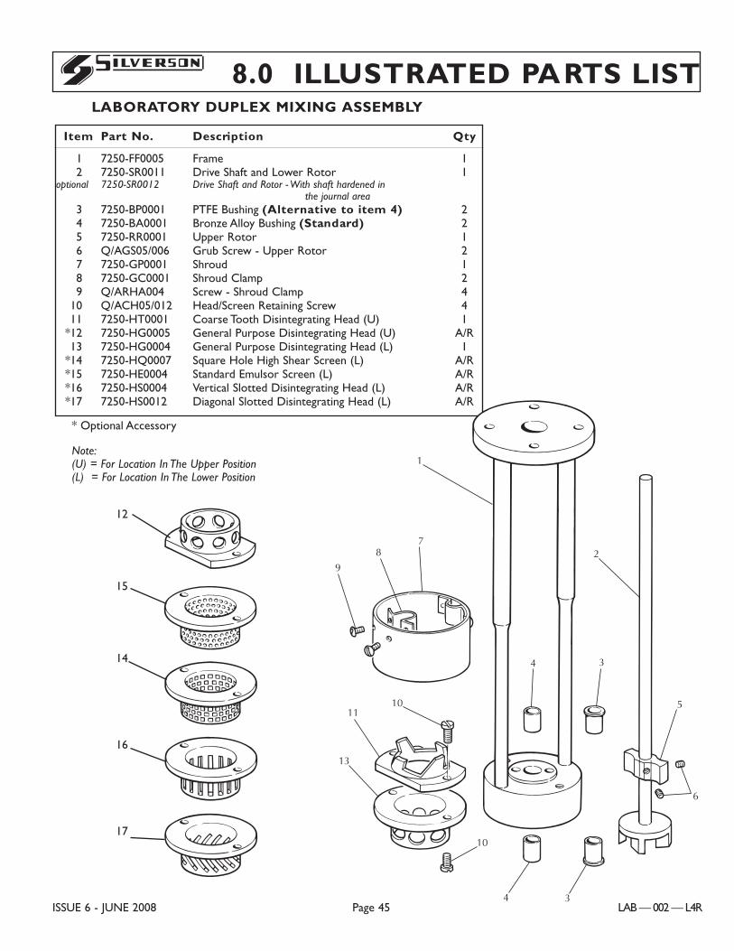
8.0 ILLUSTRATED PARTS LIST
ISSUE 6 - JUNE 2008 Page 45 LAB — 002 — L4R
S
Item Part No. Description Qty
1 7250-FF0005 Frame 12 7250-SR0011 Drive Shaft and Lower Rotor 1
optional 7250-SR0012 Drive Shaft and Rotor - With shaft hardened in the journal area
3 7250-BP0001 PTFE Bushing (Alternative to item 4) 24 7250-BA0001 Bronze Alloy Bushing (Standard) 25 7250-RR0001 Upper Rotor 16 Q/AGS05/006 Grub Screw - Upper Rotor 27 7250-GP0001 Shroud 18 7250-GC0001 Shroud Clamp 29 Q/ARHA004 Screw - Shroud Clamp 4
10 Q/ACH05/012 Head/Screen Retaining Screw 411 7250-HT0001 Coarse Tooth Disintegrating Head (U) 1
*12 7250-HG0005 General Purpose Disintegrating Head (U) A/R13 7250-HG0004 General Purpose Disintegrating Head (L) 1
*14 7250-HQ0007 Square Hole High Shear Screen (L) A/R*15 7250-HE0004 Standard Emulsor Screen (L) A/R*16 7250-HS0004 Vertical Slotted Disintegrating Head (L) A/R*17 7250-HS0012 Diagonal Slotted Disintegrating Head (L) A/R
* Optional Accessory
Note:(U) = For Location In The Upper Position(L) = For Location In The Lower Position
C0085
1
9
87
10
4 3
11
13
10
5
6
4 3
2
C0102
LABORATORY DUPLEX MIXING ASSEMBLY
12
15
14
16
17
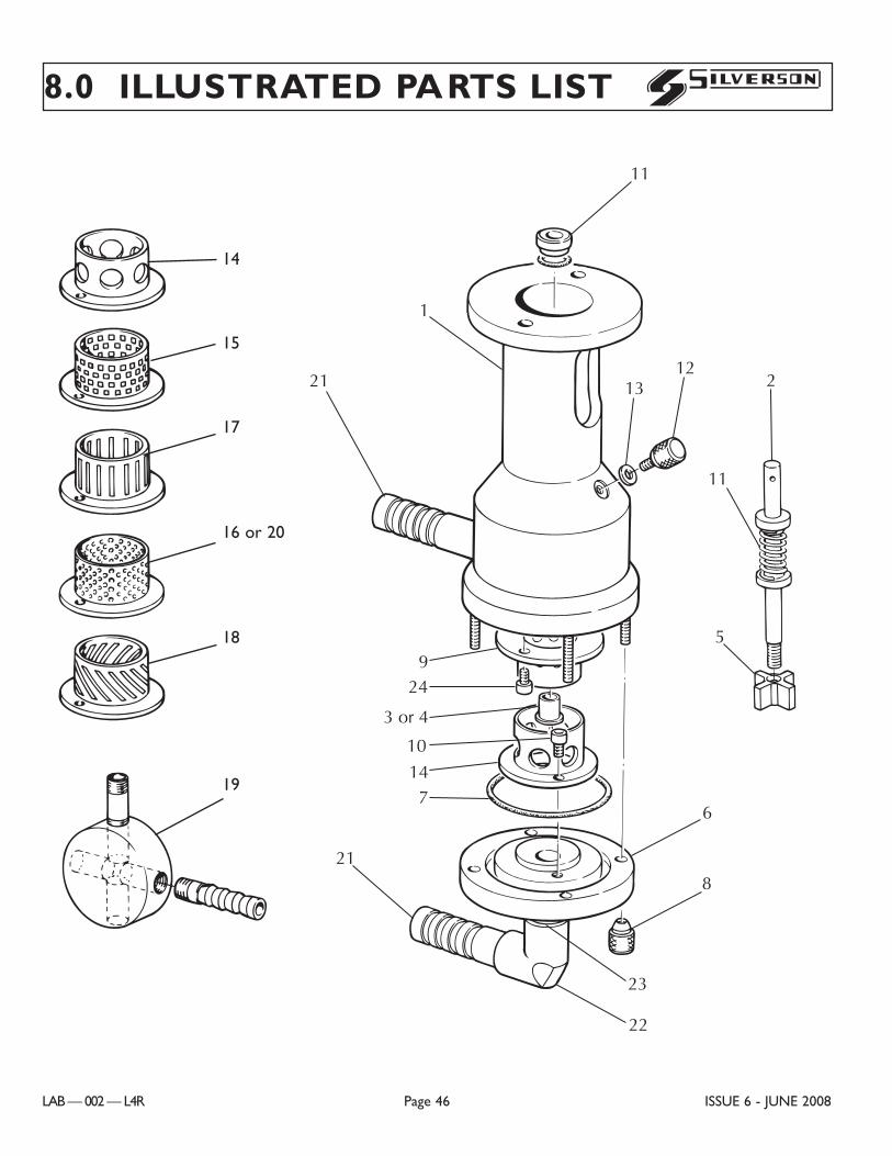
14
15
17
16 or 20
18
19
8.0 ILLUSTRATED PARTS LIST
LAB — 002 — L4R Page 46 ISSUE 6 - JUNE 2008
S
C0085
11
1
1312
21
924
3 or 4
10
147
21
6
8
23
22
C0090
2
11
5
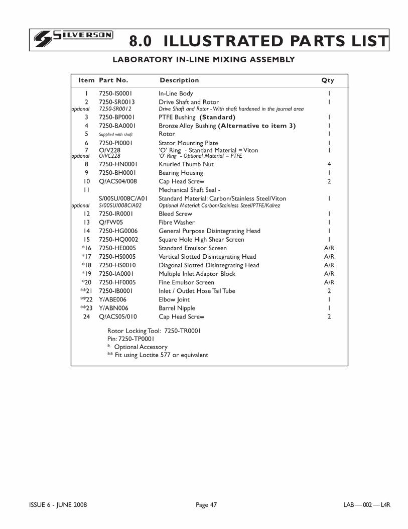
8.0 ILLUSTRATED PARTS LIST
ISSUE 6 - JUNE 2008 Page 47 LAB — 002 — L4R
S
Item Part No. Description Qty
1 7250-IS0001 In-Line Body 12 7250-SR0013 Drive Shaft and Rotor 1
optional 7250-SR0012 Drive Shaft and Rotor - With shaft hardened in the journal area
3 7250-BP0001 PTFE Bushing (Standard) 14 7250-BA0001 Bronze Alloy Bushing (Alternative to item 3) 15 Supplied with shaft Rotor 16 7250-PI0001 Stator Mounting Plate 17 O/V228 ’O’ Ring - Standard Material = Viton 1
optional O/VC228 ’O’ Ring - Optional Material = PTFE
8 7250-HN0001 Knurled Thumb Nut 49 7250-BH0001 Bearing Housing 110 Q/ACS04/008 Cap Head Screw 211 Mechanical Shaft Seal -
S/00SU/008C/A01 Standard Material: Carbon/Stainless Steel/Viton 1optional S/00SU/008C/A02 Optional Material: Carbon/Stainless Steel/PTFE/Kalrez
12 7250-IR0001 Bleed Screw 113 Q/FW05 Fibre Washer 114 7250-HG0006 General Purpose Disintegrating Head 115 7250-HQ0002 Square Hole High Shear Screen 1*16 7250-HE0005 Standard Emulsor Screen A/R*17 7250-HS0005 Vertical Slotted Disintegrating Head A/R*18 7250-HS0010 Diagonal Slotted Disintegrating Head A/R*19 7250-IA0001 Multiple Inlet Adaptor Block A/R*20 7250-HF0005 Fine Emulsor Screen A/R**21 7250-IB0001 Inlet / Outlet Hose Tail Tube 2**22 Y/ABE006 Elbow Joint 1**23 Y/ABN006 Barrel Nipple 124 Q/ACS05/010 Cap Head Screw 2
Rotor Locking Tool: 7250-TR0001Pin: 7250-TP0001* Optional Accessory** Fit using Loctite 577 or equivalent
LABORATORY IN-LINE MIXING ASSEMBLY