Embed Size (px)
Citation preview
SimMechanics™
Getting Started Guide
R2013b
How to Contact MathWorks
www.mathworks.com Webcomp.soft-sys.matlab Newsgroupwww.mathworks.com/contact_TS.html Technical Support
[email protected] Product enhancement [email protected] Bug [email protected] Documentation error [email protected] Order status, license renewals, [email protected] Sales, pricing, and general information
508-647-7000 (Phone)
508-647-7001 (Fax)
The MathWorks, Inc.3 Apple Hill DriveNatick, MA 01760-2098For contact information about worldwide offices, see the MathWorks Web site.
SimMechanics™ Getting Started Guide© COPYRIGHT 2002–2013 by The MathWorks, Inc.The software described in this document is furnished under a license agreement. The software may be usedor copied only under the terms of the license agreement. No part of this manual may be photocopied orreproduced in any form without prior written consent from The MathWorks, Inc.
FEDERAL ACQUISITION: This provision applies to all acquisitions of the Program and Documentationby, for, or through the federal government of the United States. By accepting delivery of the Programor Documentation, the government hereby agrees that this software or documentation qualifies ascommercial computer software or commercial computer software documentation as such terms are usedor defined in FAR 12.212, DFARS Part 227.72, and DFARS 252.227-7014. Accordingly, the terms andconditions of this Agreement and only those rights specified in this Agreement, shall pertain to and governthe use, modification, reproduction, release, performance, display, and disclosure of the Program andDocumentation by the federal government (or other entity acquiring for or through the federal government)and shall supersede any conflicting contractual terms or conditions. If this License fails to meet thegovernment’s needs or is inconsistent in any respect with federal procurement law, the government agreesto return the Program and Documentation, unused, to The MathWorks, Inc.
Trademarks
MATLAB and Simulink are registered trademarks of The MathWorks, Inc. Seewww.mathworks.com/trademarks for a list of additional trademarks. Other product or brandnames may be trademarks or registered trademarks of their respective holders.
Patents
MathWorks products are protected by one or more U.S. patents. Please seewww.mathworks.com/patents for more information.
Revision HistoryMarch 2012 Online only New for Version 4.0 (Release R2012a)September 2012 Online only Revised for Version 4.1 (Release R2012b)March 2013 Online only Revised for Version 4.2 (Release R2013a)September 2013 Online only Revised for Version 4.3 (Release R2013b)

Contents
Introduction to SimMechanics Software
1SimMechanics Product Description . . . . . . . . . . . . . . . . . 1-2Key Features . . . . . . . . . . . . . . . . . . . . . . . . . . . . . . . . . . . . . 1-2
Required and Related Products . . . . . . . . . . . . . . . . . . . . . 1-3SimMechanics Visualization Requirements . . . . . . . . . . . . 1-3Support for Recorded Animations . . . . . . . . . . . . . . . . . . . . 1-3Related Products . . . . . . . . . . . . . . . . . . . . . . . . . . . . . . . . . . 1-3
Representing Machines with SimMechanics Blocks . . . 1-5Open the Library . . . . . . . . . . . . . . . . . . . . . . . . . . . . . . . . . . 1-5Explore the Library . . . . . . . . . . . . . . . . . . . . . . . . . . . . . . . . 1-5
Start New Multibody Model . . . . . . . . . . . . . . . . . . . . . . . . 1-7
Multibody Model Anatomy . . . . . . . . . . . . . . . . . . . . . . . . . 1-8Basic Model Components . . . . . . . . . . . . . . . . . . . . . . . . . . . 1-8Applying Forces and Torques . . . . . . . . . . . . . . . . . . . . . . . . 1-11Sensing Motion . . . . . . . . . . . . . . . . . . . . . . . . . . . . . . . . . . . 1-13
Multibody Modeling Workflow . . . . . . . . . . . . . . . . . . . . . . 1-16Model Rigid Bodies . . . . . . . . . . . . . . . . . . . . . . . . . . . . . . . . 1-16Assemble Multibody Model . . . . . . . . . . . . . . . . . . . . . . . . . . 1-21Add Forces, Torques, and Motion Sensors . . . . . . . . . . . . . . 1-24Simulate and Analyze model . . . . . . . . . . . . . . . . . . . . . . . . 1-28
Model Simple Link . . . . . . . . . . . . . . . . . . . . . . . . . . . . . . . . . 1-32Model Overview . . . . . . . . . . . . . . . . . . . . . . . . . . . . . . . . . . . 1-32Build Model . . . . . . . . . . . . . . . . . . . . . . . . . . . . . . . . . . . . . . 1-33Generate Subsystem . . . . . . . . . . . . . . . . . . . . . . . . . . . . . . . 1-34Visualize Model . . . . . . . . . . . . . . . . . . . . . . . . . . . . . . . . . . . 1-35Save Model . . . . . . . . . . . . . . . . . . . . . . . . . . . . . . . . . . . . . . . 1-36Model Simple Pendulum . . . . . . . . . . . . . . . . . . . . . . . . . . . . 1-36
iii
Model Pendulum . . . . . . . . . . . . . . . . . . . . . . . . . . . . . . . . . . 1-37Model Overview . . . . . . . . . . . . . . . . . . . . . . . . . . . . . . . . . . . 1-37Build Model . . . . . . . . . . . . . . . . . . . . . . . . . . . . . . . . . . . . . . 1-38Specify Gravity . . . . . . . . . . . . . . . . . . . . . . . . . . . . . . . . . . . 1-39Add Motion Sensing . . . . . . . . . . . . . . . . . . . . . . . . . . . . . . . 1-40Guide Model Assembly . . . . . . . . . . . . . . . . . . . . . . . . . . . . . 1-41Assemble and Simulate Model . . . . . . . . . . . . . . . . . . . . . . . 1-41Save Model . . . . . . . . . . . . . . . . . . . . . . . . . . . . . . . . . . . . . . . 1-43
Modeling with SimMechanics First and SecondGenerations . . . . . . . . . . . . . . . . . . . . . . . . . . . . . . . . . . . . . 1-44
iv Contents
1
Introduction toSimMechanics Software
• “SimMechanics Product Description” on page 1-2
• “Required and Related Products” on page 1-3
• “Representing Machines with SimMechanics Blocks” on page 1-5
• “Start New Multibody Model” on page 1-7
• “Multibody Model Anatomy” on page 1-8
• “Multibody Modeling Workflow” on page 1-16
• “Model Simple Link” on page 1-32
• “Model Pendulum” on page 1-37
• “Modeling with SimMechanics First and Second Generations” on page 1-44
1 Introduction to SimMechanics™ Software
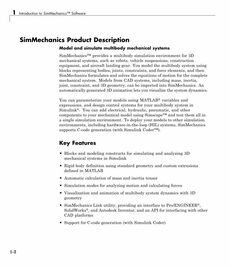
SimMechanics Product DescriptionModel and simulate multibody mechanical systems
SimMechanics™ provides a multibody simulation environment for 3Dmechanical systems, such as robots, vehicle suspensions, constructionequipment, and aircraft landing gear. You model the multibody system usingblocks representing bodies, joints, constraints, and force elements, and thenSimMechanics formulates and solves the equations of motion for the completemechanical system. Models from CAD systems, including mass, inertia,joint, constraint, and 3D geometry, can be imported into SimMechanics. Anautomatically generated 3D animation lets you visualize the system dynamics.
You can parameterize your models using MATLAB® variables andexpressions, and design control systems for your multibody system inSimulink®. You can add electrical, hydraulic, pneumatic, and othercomponents to your mechanical model using Simscape™ and test them all ina single simulation environment. To deploy your models to other simulationenvironments, including hardware-in-the-loop (HIL) systems, SimMechanicssupports C-code generation (with Simulink Coder™).
Key Features
• Blocks and modeling constructs for simulating and analyzing 3Dmechanical systems in Simulink
• Rigid body definition using standard geometry and custom extrusionsdefined in MATLAB
• Automatic calculation of mass and inertia tensor
• Simulation modes for analyzing motion and calculating forces
• Visualization and animation of multibody system dynamics with 3Dgeometry
• SimMechanics Link utility, providing an interface to Pro/ENGINEER®,SolidWorks®, and Autodesk Inventor, and an API for interfacing with otherCAD platforms
• Support for C-code generation (with Simulink Coder)
1-2
Required and Related Products
Required and Related Products
In this section...
“SimMechanics Visualization Requirements” on page 1-3
“Support for Recorded Animations” on page 1-3
“Related Products” on page 1-3
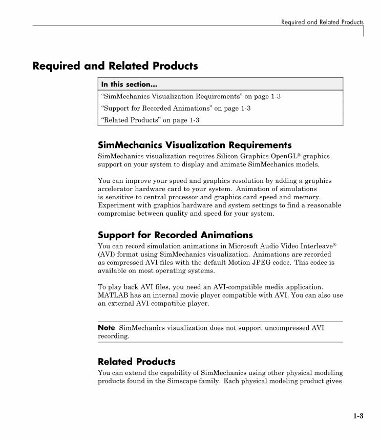
SimMechanics Visualization RequirementsSimMechanics visualization requires Silicon Graphics OpenGL® graphicssupport on your system to display and animate SimMechanics models.
You can improve your speed and graphics resolution by adding a graphicsaccelerator hardware card to your system. Animation of simulationsis sensitive to central processor and graphics card speed and memory.Experiment with graphics hardware and system settings to find a reasonablecompromise between quality and speed for your system.
Support for Recorded AnimationsYou can record simulation animations in Microsoft Audio Video Interleave®
(AVI) format using SimMechanics visualization. Animations are recordedas compressed AVI files with the default Motion JPEG codec. This codec isavailable on most operating systems.
To play back AVI files, you need an AVI-compatible media application.MATLAB has an internal movie player compatible with AVI. You can also usean external AVI-compatible player.
Note SimMechanics visualization does not support uncompressed AVIrecording.
Related ProductsYou can extend the capability of SimMechanics using other physical modelingproducts found in the Simscape family. Each physical modeling product gives
1-3
1 Introduction to SimMechanics™ Software
you a set of block libraries with which you can model common componentsfound in industry and academia: rigid bodies, gears, valves, solenoids, etc.
With the physical modeling products, you can model not only mechanicalsystems, but also electrical, hydraulic, and power systems. You can modeleach system separately, and then integrate the systems into a singlemultiphysics model where you can analyze combined system performance.
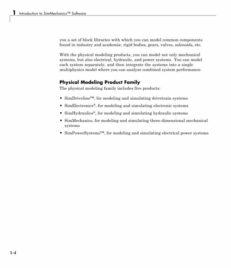
Physical Modeling Product FamilyThe physical modeling family includes five products:
• SimDriveline™, for modeling and simulating drivetrain systems
• SimElectronics®, for modeling and simulating electronic systems
• SimHydraulics®, for modeling and simulating hydraulic systems
• SimMechanics, for modeling and simulating three-dimensional mechanicalsystems
• SimPowerSystems™, for modeling and simulating electrical power systems
1-4
Representing Machines with SimMechanics™ Blocks
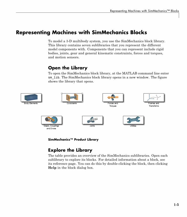
Representing Machines with SimMechanics BlocksTo model a 3-D multibody system, you use the SimMechanics block library.This library contains seven sublibraries that you represent the differentmodel components with. Components that you can represent include rigidbodies, joints, gear and general kinematic constraints, forces and torques,and motion sensors.
Open the LibraryTo open the SimMechanics block library, at the MATLAB command line entersm_lib. The SimMechanics block library opens in a new window. The figureshows the library that opens.
SimMechanics™ Product Library
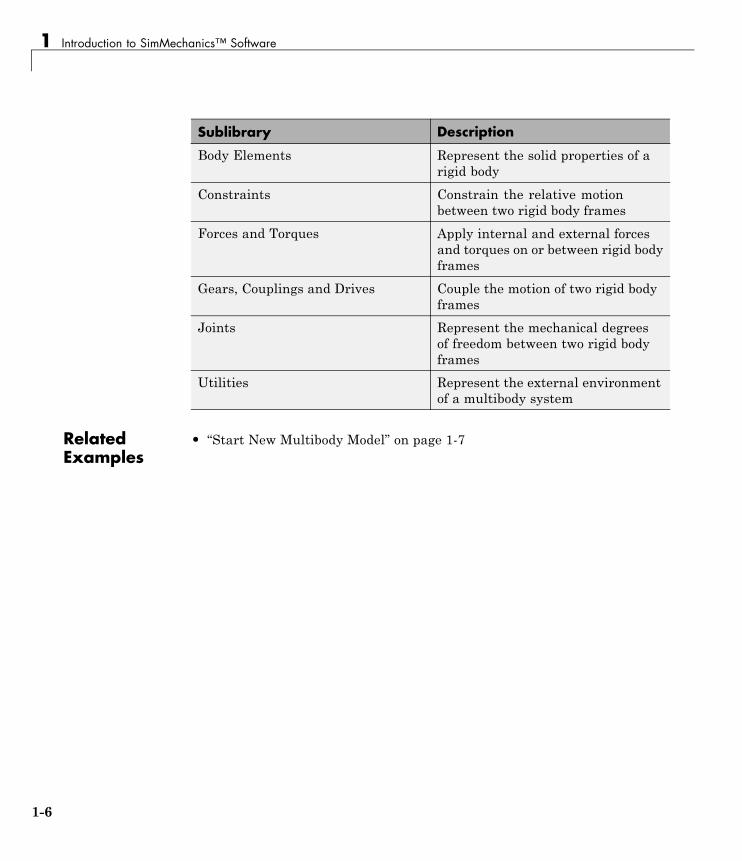
Explore the LibraryThe table provides an overview of the SimMechanics sublibraries. Open eachsublibrary to explore its blocks. For detailed information about a block, seeits reference page. You can do this by double-clicking the block, then clickingHelp in the block dialog box.
1-5
1 Introduction to SimMechanics™ Software
Sublibrary Description
Body Elements Represent the solid properties of arigid body
Constraints Constrain the relative motionbetween two rigid body frames
Forces and Torques Apply internal and external forcesand torques on or between rigid bodyframes
Gears, Couplings and Drives Couple the motion of two rigid bodyframes
Joints Represent the mechanical degreesof freedom between two rigid bodyframes
Utilities Represent the external environmentof a multibody system
RelatedExamples
• “Start New Multibody Model” on page 1-7
1-6
Start New Multibody Model
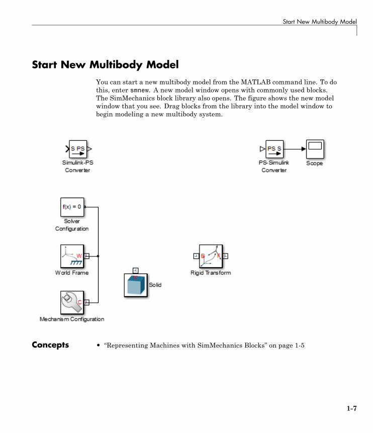
Start New Multibody ModelYou can start a new multibody model from the MATLAB command line. To dothis, enter smnew. A new model window opens with commonly used blocks.The SimMechanics block library also opens. The figure shows the new modelwindow that you see. Drag blocks from the library into the model window tobegin modeling a new multibody system.
Concepts • “Representing Machines with SimMechanics Blocks” on page 1-5
1-7
1 Introduction to SimMechanics™ Software
Multibody Model Anatomy
In this section...
“Basic Model Components” on page 1-8
“Applying Forces and Torques” on page 1-11
“Sensing Motion” on page 1-13
With SimMechanics, you represent a multibody system using blocks. Like allphysical modeling products, each block represents a physical component oran abstract entity fundamental to physical modeling, e.g. frames and frametransforms.
By connecting the blocks with connection lines, you define the relationshipsthat unite the physical components into a single system (or subsystem). In abasic model, these physical components include rigid bodies and joints. Youcan also add forces and torques, motion sensors, and kinematic constraintssuch as gears.
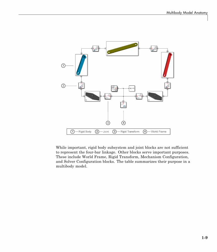
Basic Model ComponentsThe figure shows the block diagram of a multibody system—the four-barlinkage. This model contains subsystem blocks to represent the links andpivot mounts. These represent the rigid bodies of the model. The modelcontains also four Revolute Joint blocks. These represent the joints in themodel. Combined, these blocks form the foundation of this model.
1-8
Multibody Model Anatomy
While important, rigid body subsystem and joint blocks are not sufficientto represent the four-bar linkage. Other blocks serve important purposes.These include World Frame, Rigid Transform, Mechanism Configuration,and Solver Configuration blocks. The table summarizes their purpose in amultibody model.
1-9
1 Introduction to SimMechanics™ Software
Block Purpose
World Frame Provides the ultimate referenceframe in a model. All remainingframes are defined with respectto this frame. It is inertial and itdefines absolute rest.
Rigid Transform Applies a fixed spatial relationshipbetween frames. This block definesthe offset distance and angle betweentwo frames.
Mechanism Configuration Identifies the gravity vector in amodel.
Solver Configuration Provides essential simulationparameters required to simulate themodel.
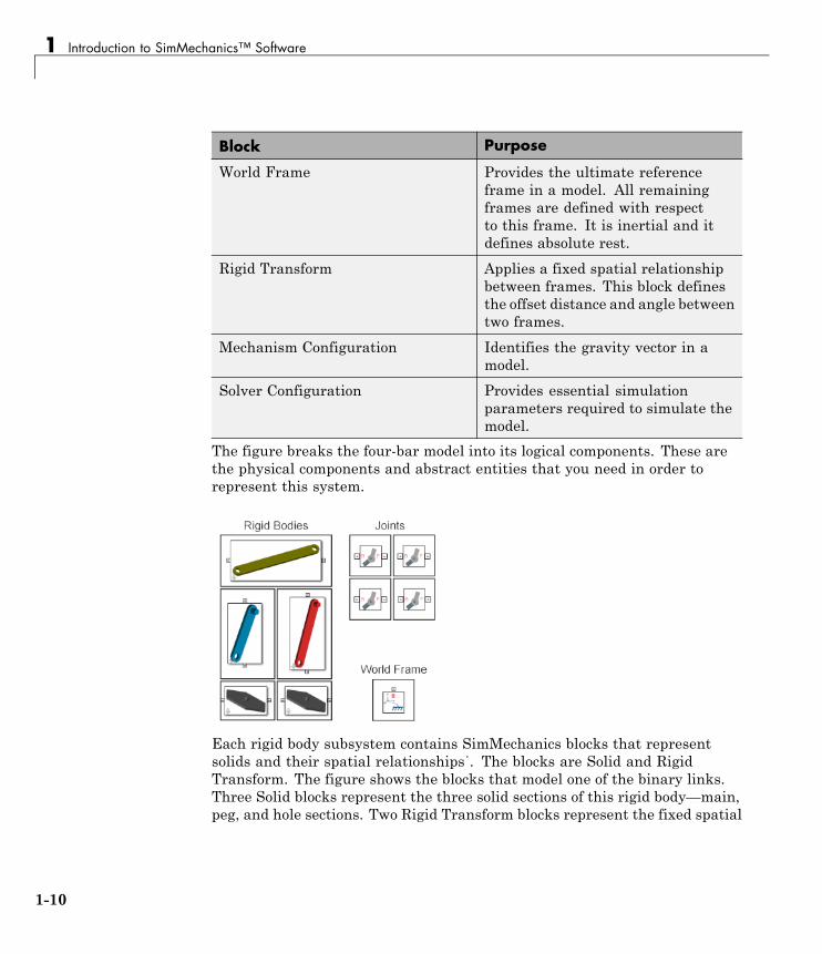
The figure breaks the four-bar model into its logical components. These arethe physical components and abstract entities that you need in order torepresent this system.
Each rigid body subsystem contains SimMechanics blocks that representsolids and their spatial relationships˙. The blocks are Solid and RigidTransform. The figure shows the blocks that model one of the binary links.Three Solid blocks represent the three solid sections of this rigid body—main,peg, and hole sections. Two Rigid Transform blocks represent the fixed spatial
1-10
Multibody Model Anatomy
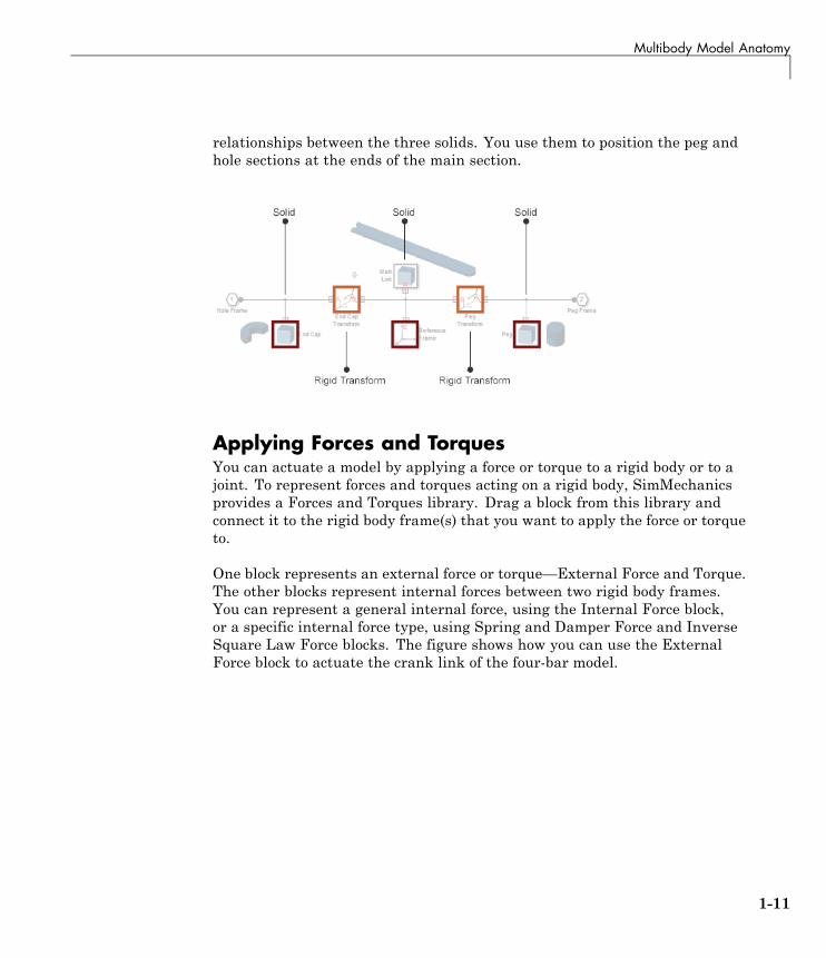
relationships between the three solids. You use them to position the peg andhole sections at the ends of the main section.
Applying Forces and TorquesYou can actuate a model by applying a force or torque to a rigid body or to ajoint. To represent forces and torques acting on a rigid body, SimMechanicsprovides a Forces and Torques library. Drag a block from this library andconnect it to the rigid body frame(s) that you want to apply the force or torqueto.
One block represents an external force or torque—External Force and Torque.The other blocks represent internal forces between two rigid body frames.You can represent a general internal force, using the Internal Force block,or a specific internal force type, using Spring and Damper Force and InverseSquare Law Force blocks. The figure shows how you can use the ExternalForce block to actuate the crank link of the four-bar model.
1-11
1 Introduction to SimMechanics™ Software
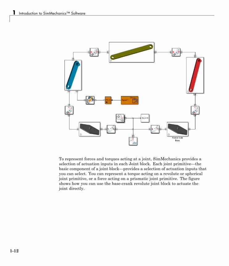
To represent forces and torques acting at a joint, SimMechanics provides aselection of actuation inputs in each Joint block. Each joint primitive—thebasic component of a joint block—provides a selection of actuation inputs thatyou can select. You can represent a torque acting on a revolute or sphericaljoint primitive, or a force acting on a prismatic joint primitive. The figureshows how you can use the base-crank revolute joint block to actuate thejoint directly.
1-12
Multibody Model Anatomy
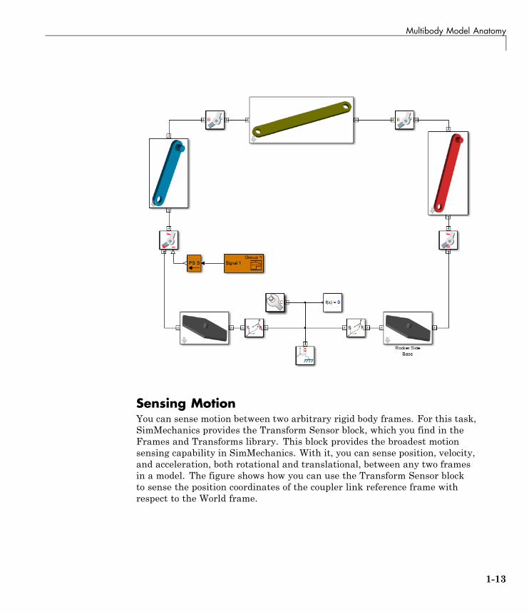
Sensing MotionYou can sense motion between two arbitrary rigid body frames. For this task,SimMechanics provides the Transform Sensor block, which you find in theFrames and Transforms library. This block provides the broadest motionsensing capability in SimMechanics. With it, you can sense position, velocity,and acceleration, both rotational and translational, between any two framesin a model. The figure shows how you can use the Transform Sensor blockto sense the position coordinates of the coupler link reference frame withrespect to the World frame.
1-13
1 Introduction to SimMechanics™ Software
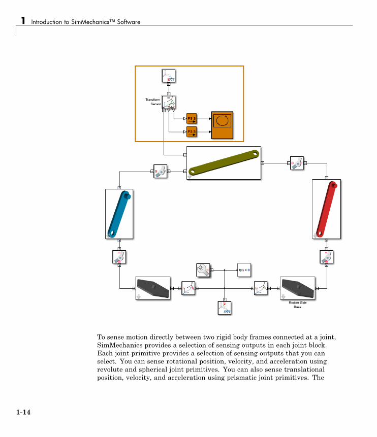
To sense motion directly between two rigid body frames connected at a joint,SimMechanics provides a selection of sensing outputs in each joint block.Each joint primitive provides a selection of sensing outputs that you canselect. You can sense rotational position, velocity, and acceleration usingrevolute and spherical joint primitives. You can also sense translationalposition, velocity, and acceleration using prismatic joint primitives. The
1-14
Multibody Model Anatomy
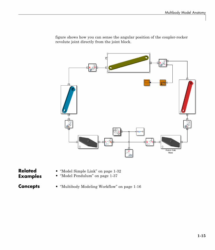
figure shows how you can sense the angular position of the coupler-rockerrevolute joint directly from the joint block.
RelatedExamples
• “Model Simple Link” on page 1-32• “Model Pendulum” on page 1-37
Concepts • “Multibody Modeling Workflow” on page 1-16
1-15
1 Introduction to SimMechanics™ Software
Multibody Modeling Workflow
In this section...
“Model Rigid Bodies” on page 1-16
“Assemble Multibody Model” on page 1-21
“Add Forces, Torques, and Motion Sensors” on page 1-24
“Simulate and Analyze model” on page 1-28
The multibody modeling process contains a set of well-defined, sequentialsteps. Before you begin, define the intent of the model. Then, select amodeling approach and define the model requirements.
SimMechanics supports two modeling approaches:
• Manually build model — most common modeling approach. The followingsections outline the manual approach.
• Automatically generate model from CAD assembly — for users wishing tosimulate a CAD assembly in a physical modeling environment. Approachrequires access to supported CAD software and assembly files. See “CADTranslation”.
Model Rigid BodiesRigid bodies are the building blocks of a multibody system. Before you canconnect rigid bodies with joints and constraints, you must model the rigidbodies. You can create two types of rigid bodies:
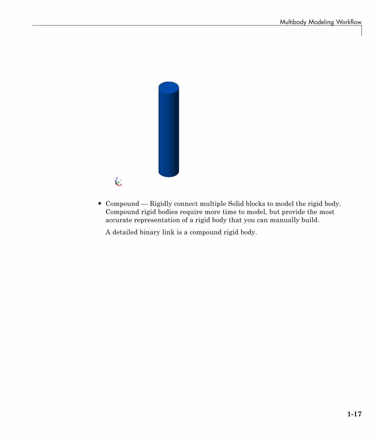
• Simple — Use a single Solid block to model the rigid body. Simple rigidbodies are quicker to model. Use simple rigid bodies to quickly produceproof-of-concept models, before you create more detailed rigid bodysubsystems.
A simple cylinder is a simple rigid body.
1-16
Multibody Modeling Workflow
• Compound — Rigidly connect multiple Solid blocks to model the rigid body.Compound rigid bodies require more time to model, but provide the mostaccurate representation of a rigid body that you can manually build.
A detailed binary link is a compound rigid body.
1-17
1 Introduction to SimMechanics™ Software
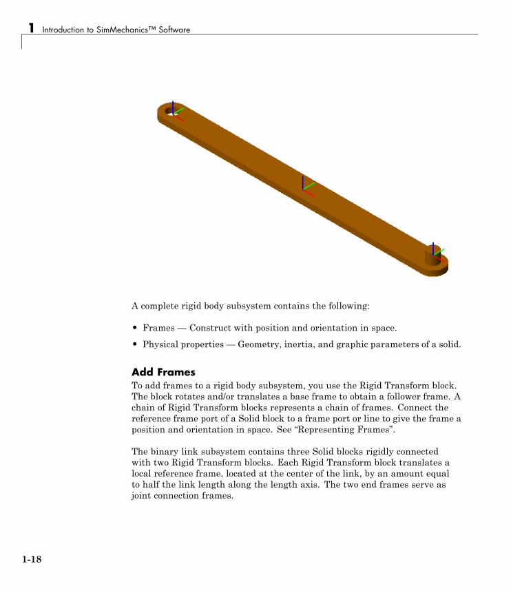
A complete rigid body subsystem contains the following:
• Frames — Construct with position and orientation in space.
• Physical properties — Geometry, inertia, and graphic parameters of a solid.
Add FramesTo add frames to a rigid body subsystem, you use the Rigid Transform block.The block rotates and/or translates a base frame to obtain a follower frame. Achain of Rigid Transform blocks represents a chain of frames. Connect thereference frame port of a Solid block to a frame port or line to give the frame aposition and orientation in space. See “Representing Frames”.
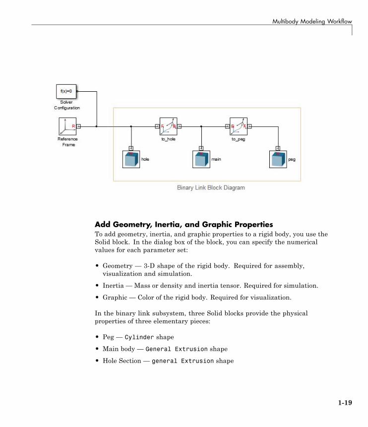
The binary link subsystem contains three Solid blocks rigidly connectedwith two Rigid Transform blocks. Each Rigid Transform block translates alocal reference frame, located at the center of the link, by an amount equalto half the link length along the length axis. The two end frames serve asjoint connection frames.
1-18
Multibody Modeling Workflow
Add Geometry, Inertia, and Graphic PropertiesTo add geometry, inertia, and graphic properties to a rigid body, you use theSolid block. In the dialog box of the block, you can specify the numericalvalues for each parameter set:
• Geometry — 3-D shape of the rigid body. Required for assembly,visualization and simulation.
• Inertia — Mass or density and inertia tensor. Required for simulation.
• Graphic — Color of the rigid body. Required for visualization.
In the binary link subsystem, three Solid blocks provide the physicalproperties of three elementary pieces:
• Peg — Cylinder shape
• Main body — General Extrusion shape
• Hole Section — general Extrusion shape
1-19
1 Introduction to SimMechanics™ Software
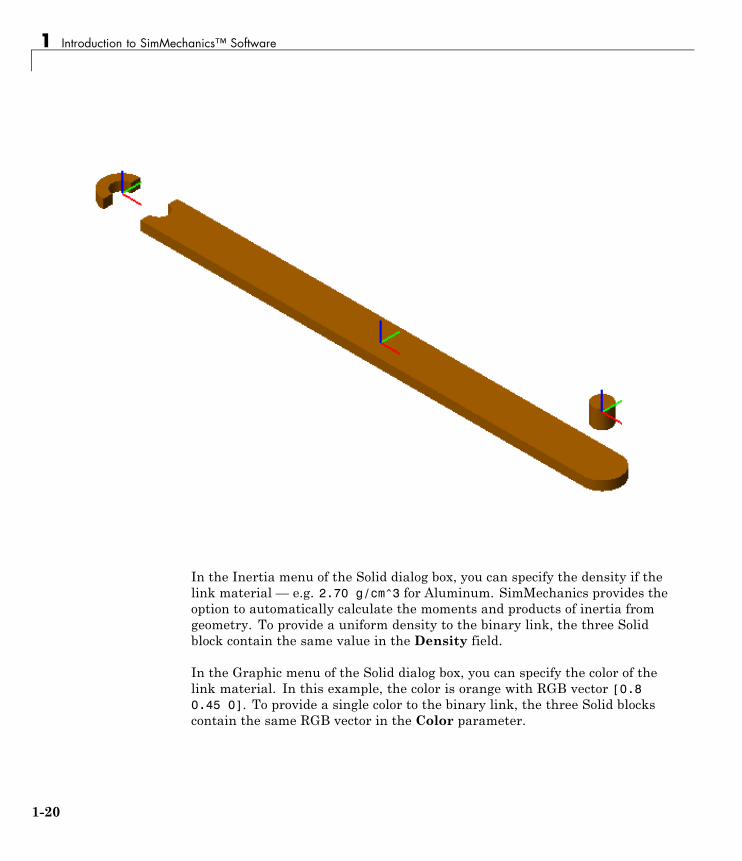
In the Inertia menu of the Solid dialog box, you can specify the density if thelink material — e.g. 2.70 g/cm^3 for Aluminum. SimMechanics provides theoption to automatically calculate the moments and products of inertia fromgeometry. To provide a uniform density to the binary link, the three Solidblock contain the same value in the Density field.
In the Graphic menu of the Solid dialog box, you can specify the color of thelink material. In this example, the color is orange with RGB vector [0.80.45 0]. To provide a single color to the binary link, the three Solid blockscontain the same RGB vector in the Color parameter.
1-20

Multibody Modeling Workflow
Assemble Multibody ModelOnce you have created the rigid body subsystems, you can assemble thesubsystems into a mechanism or machine. In a mechanism or machine, jointsand constraints provide well-defined degrees of freedom that constrain rigidbody motion. Two types of motion are possible:
• Rotation about one or more axes
• Translation along one or more axes
Connect JointsTo assemble rigid body subsystems into complete multibody systems, connectthe with joints. SimMechanics provides a library with fourteen joint blocks.Each block provides a different number and/or type of mechanical degrees offreedom. Exactly two rigid body frames connect to each joint, with each framebelonging to a different rigid body.
Joints are composed of joint primitives — elementary joints that you cancombine to create more complex joints. SimMechanics contains three jointprimitives:
• Prismatic — one translational degree of freedom along an axis
• Revolute — one rotational degree of freedom about an axis
• Spherical — three concurrent degrees of freedom about three axes
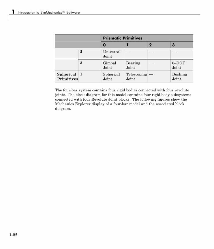
The following table identifies the joint primitives associated with each joint.
Prismatic Primitives
0 1 2 3
0 Weld Joint PrismaticJoint
RectangularJoint
CartesianJoint
1 RevoluteJoint
CylindricalJoint
PlanarJoint
—
RevolutePrimitives
1-21
1 Introduction to SimMechanics™ Software
Prismatic Primitives
0 1 2 3
2 UniversalJoint
— — —
3 GimbalJoint
BearingJoint
— 6–DOFJoint
SphericalPrimitives
1 SphericalJoint
TelescopingJoint
— BushingJoint
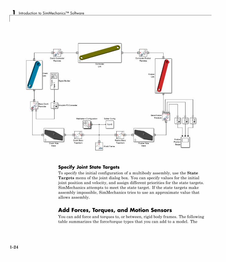
The four-bar system contains four rigid bodies connected with four revolutejoints. The block diagram for this model contains four rigid body subsystemsconnected with four Revolute Joint blocks. The following figures show theMechanics Explorer display of a four-bar model and the associated blockdiagram.
1-22
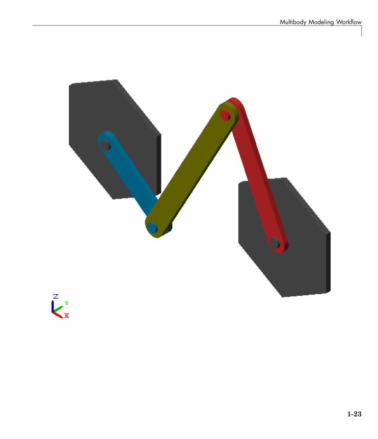
Multibody Modeling Workflow
1-23
1 Introduction to SimMechanics™ Software
Specify Joint State TargetsTo specify the initial configuration of a multibody assembly, use the StateTargets menu of the joint dialog box. You can specify values for the initialjoint position and velocity, and assign different priorities for the state targets.SimMechanics attempts to meet the state target. If the state targets makeassembly impossible, SimMechanics tries to use an approximate value thatallows assembly.
Add Forces, Torques, and Motion SensorsYou can add force and torques to, or between, rigid body frames. The followingtable summarizes the force/torque types that you can add to a model. The
1-24
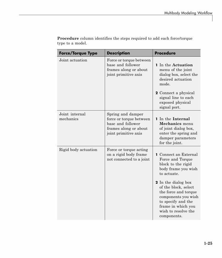
Multibody Modeling Workflow
Procedure column identifies the steps required to add each force/torquetype to a model.
Force/Torque Type Description Procedure
Joint actuation Force or torque betweenbase and followerframes along or aboutjoint primitive axis
1 In the Actuationmenu of the jointdialog box, select thedesired actuationmode.
2 Connect a physicalsignal line to eachexposed physicalsignal port.
Joint internalmechanics
Spring and damperforce or torque betweenbase and followerframes along or aboutjoint primitive axis
1 In the InternalMechanics menuof joint dialog box,enter the spring anddamper parametersfor the joint.
Rigid body actuation Force or torque actingon a rigid body framenot connected to a joint
1 Connect an ExternalForce and Torqueblock to the rigidbody frame you wishto actuate.
2 In the dialog boxof the block, selectthe force and torquecomponents you wishto specify and theframe in which youwish to resolve thecomponents.
1-25
1 Introduction to SimMechanics™ Software
Force/Torque Type Description Procedure
3 Connect a physicalsignal line to eachexposed physicalsignal port.
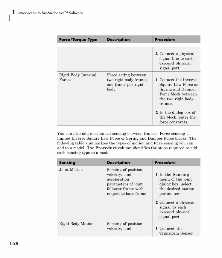
Rigid Body InternalForces
Force acting betweentwo rigid body frames,one frame per rigidbody
1 Connect the InverseSquare Law Force orSpring and DamperForce block betweenthe two rigid bodyframes.
2 In the dialog box ofthe block, enter theforce constants.
You can also add mechanical sensing between frames. Force sensing islimited Inverse Square Law Force or Spring and Damper Force blocks. Thefollowing table summarizes the types of motion and force sensing you canadd to a model. The Procedure column identifies the steps required to addeach sensing type to a model.
Sensing Description Procedure
Joint Motion Sensing of position,velocity, andaccelerationparameters of jointfollower frame withrespect to base frame
1 In the Sensingmenu of the jointdialog box, selectthe desired motionparameter.
2 Connect a physicalsignal to eachexposed physicalsignal port.
Rigid Body Motion Sensing of position,velocity, and 1 Connect the
Transform Sensor
1-26
Multibody Modeling Workflow
Sensing Description Procedure
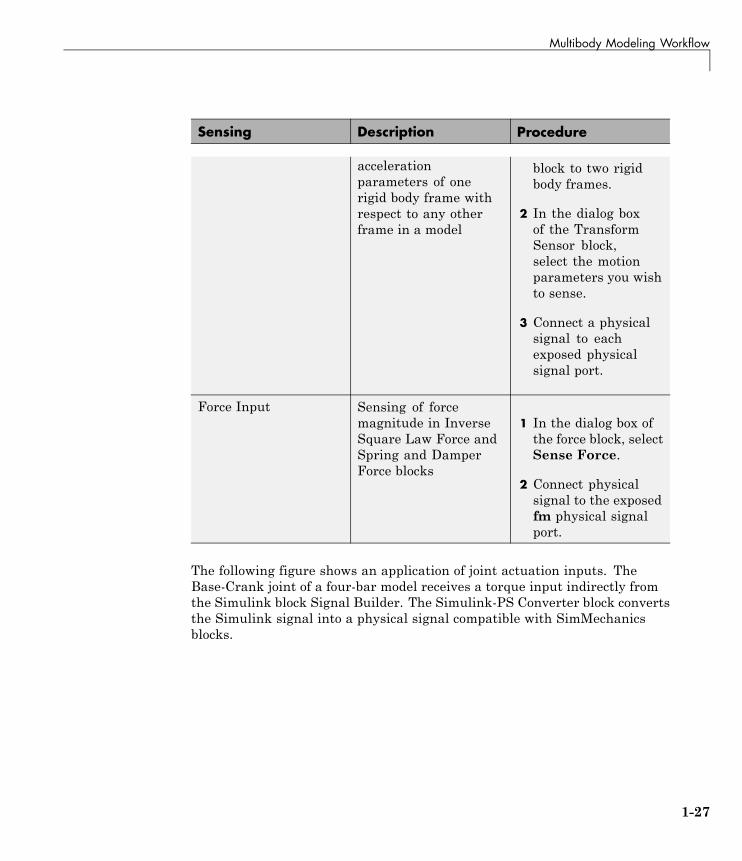
accelerationparameters of onerigid body frame withrespect to any otherframe in a model
block to two rigidbody frames.
2 In the dialog boxof the TransformSensor block,select the motionparameters you wishto sense.
3 Connect a physicalsignal to eachexposed physicalsignal port.
Force Input Sensing of forcemagnitude in InverseSquare Law Force andSpring and DamperForce blocks
1 In the dialog box ofthe force block, selectSense Force.
2 Connect physicalsignal to the exposedfm physical signalport.
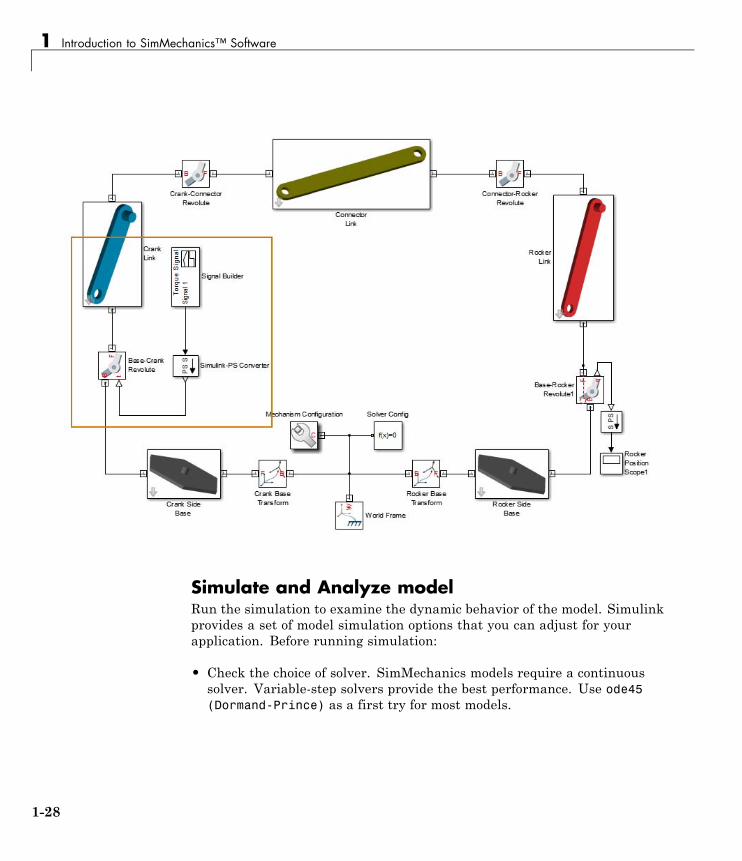
The following figure shows an application of joint actuation inputs. TheBase-Crank joint of a four-bar model receives a torque input indirectly fromthe Simulink block Signal Builder. The Simulink-PS Converter block convertsthe Simulink signal into a physical signal compatible with SimMechanicsblocks.
1-27
1 Introduction to SimMechanics™ Software
Simulate and Analyze modelRun the simulation to examine the dynamic behavior of the model. Simulinkprovides a set of model simulation options that you can adjust for yourapplication. Before running simulation:
• Check the choice of solver. SimMechanics models require a continuoussolver. Variable-step solvers provide the best performance. Use ode45(Dormand-Prince) as a first try for most models.
1-28
Multibody Modeling Workflow
• Check the solver step sizes and tolerances. Smaller values for bothparameters produce more accurate results at the cost of increasedsimulation time.
• Check the simulation time span. To let a simulation run indefinitely,specify inf in the Stop time field.
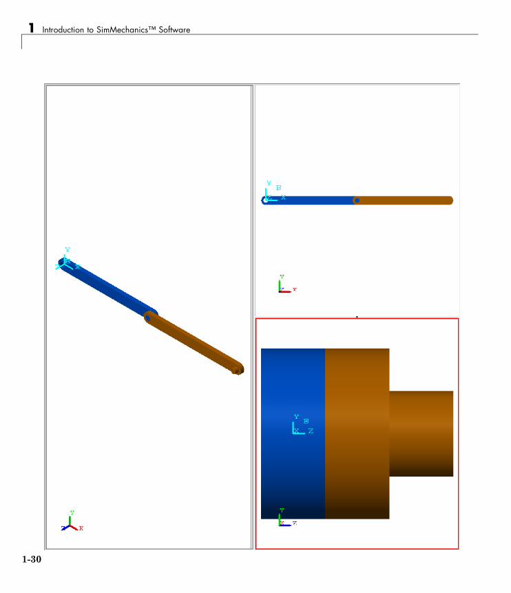
The Mechanics Explorer utility provides 3-D visualization for SimMechanicsmodels. By default, the utility opens the first time you update a model, andrefreshes for all subsequent model updates. The following figure shows theMechanics Explorer display of a double-pendulum model.
1-29
1 Introduction to SimMechanics™ Software
1-30
Multibody Modeling Workflow
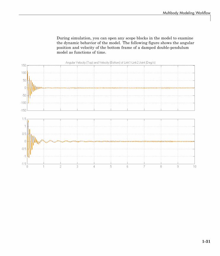
During simulation, you can open any scope blocks in the model to examinethe dynamic behavior of the model. The following figure shows the angularposition and velocity of the bottom frame of a damped double-pendulummodel as functions of time.
1-31
1 Introduction to SimMechanics™ Software
Model Simple Link
In this section...
“Model Overview” on page 1-32
“Build Model” on page 1-33
“Generate Subsystem” on page 1-34
“Visualize Model” on page 1-35
“Save Model” on page 1-36
“Model Simple Pendulum” on page 1-36
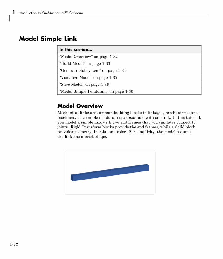
Model OverviewMechanical links are common building blocks in linkages, mechanisms, andmachines. The simple pendulum is an example with one link. In this tutorial,you model a simple link with two end frames that you can later connect tojoints. Rigid Transform blocks provide the end frames, while a Solid blockprovides geometry, inertia, and color. For simplicity, the model assumesthe link has a brick shape.
1-32
Model Simple Link
Build Model
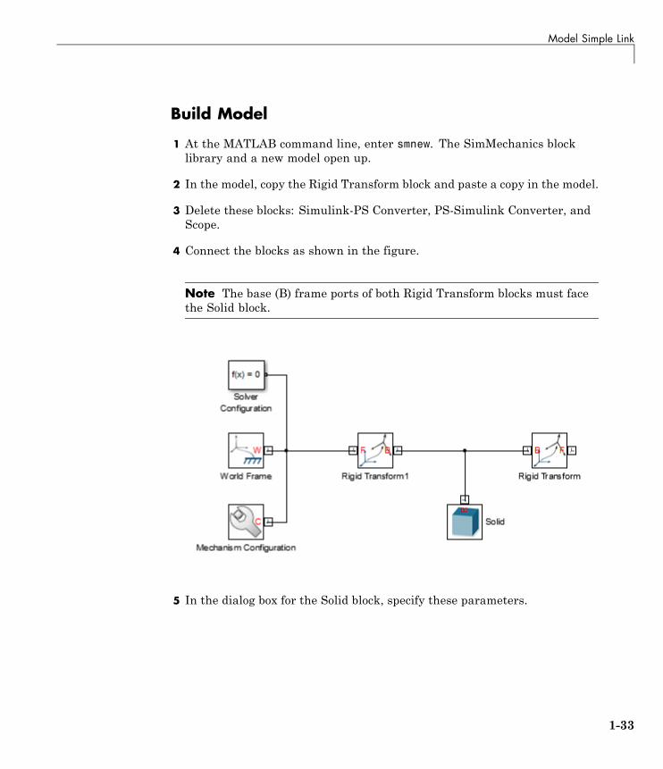
1 At the MATLAB command line, enter smnew. The SimMechanics blocklibrary and a new model open up.
2 In the model, copy the Rigid Transform block and paste a copy in the model.
3 Delete these blocks: Simulink-PS Converter, PS-Simulink Converter, andScope.
4 Connect the blocks as shown in the figure.
Note The base (B) frame ports of both Rigid Transform blocks must facethe Solid block.
5 In the dialog box for the Solid block, specify these parameters.
1-33
1 Introduction to SimMechanics™ Software
Parameter Value
Geometry > Dimensions [L W H] cm
Inertia > Density rho kg/m^3
Graphic > VisualProperties > Color
rgb
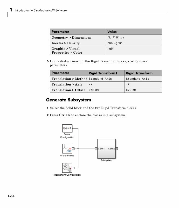
6 In the dialog boxes for the Rigid Transform blocks, specify theseparameters.
Parameter Rigid Transform1 Rigid Transform
Translation > Method Standard Axis Standard Axis
Translation > Axis -X +X
Translation > Offset L/2 cm L/2 cm
Generate Subsystem
1 Select the Solid block and the two Rigid Transform blocks.
2 Press Ctrl+G to enclose the blocks in a subsystem.
1-34
Model Simple Link
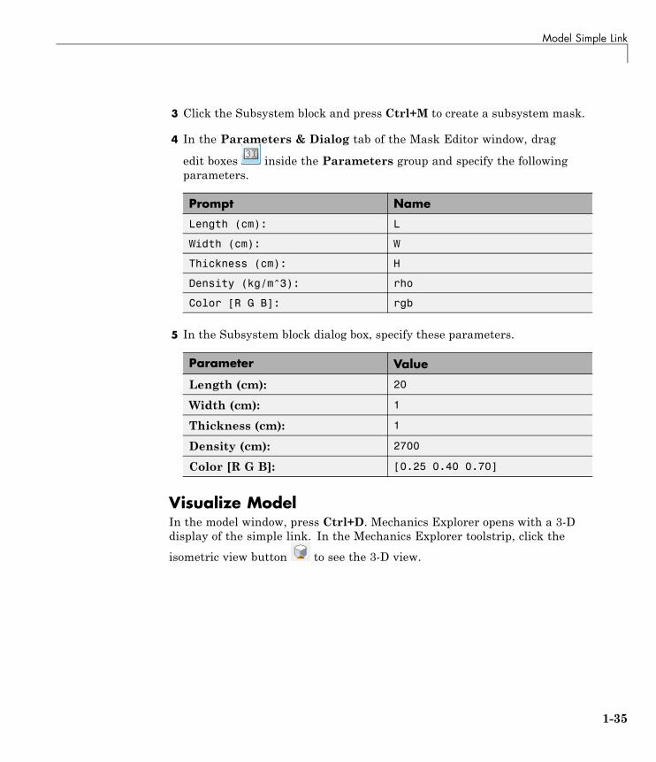
3 Click the Subsystem block and press Ctrl+M to create a subsystem mask.
4 In the Parameters & Dialog tab of the Mask Editor window, drag
edit boxes inside the Parameters group and specify the followingparameters.
Prompt Name
Length (cm): L
Width (cm): W
Thickness (cm): H
Density (kg/m^3): rho
Color [R G B]: rgb
5 In the Subsystem block dialog box, specify these parameters.
Parameter Value
Length (cm): 20
Width (cm): 1
Thickness (cm): 1
Density (cm): 2700
Color [R G B]: [0.25 0.40 0.70]
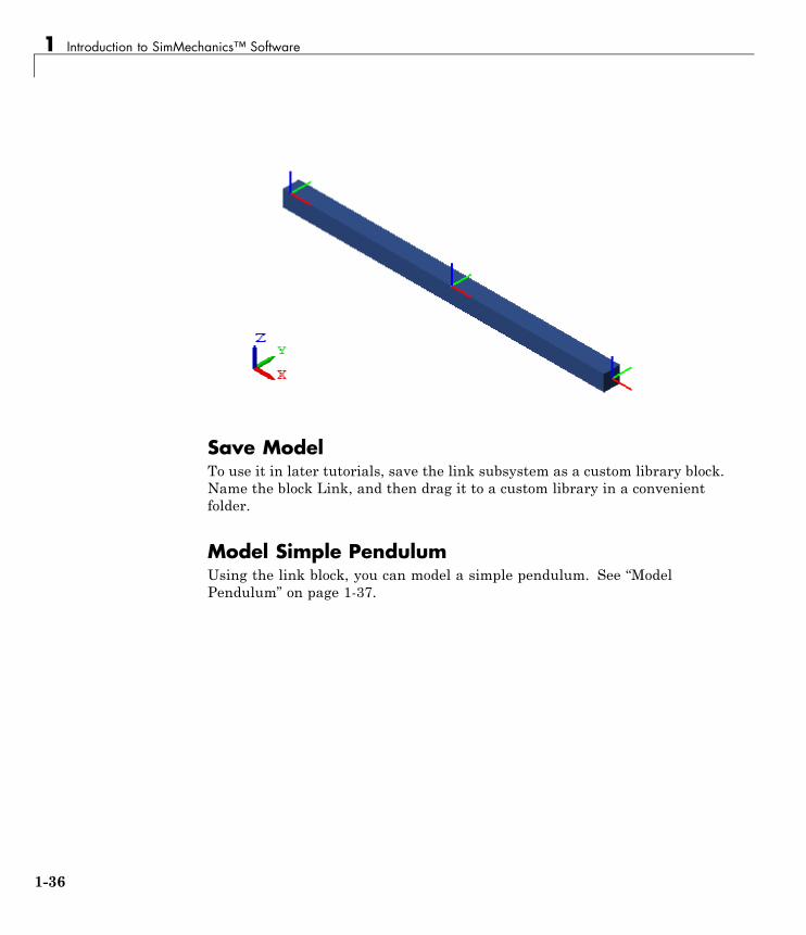
Visualize ModelIn the model window, press Ctrl+D. Mechanics Explorer opens with a 3-Ddisplay of the simple link. In the Mechanics Explorer toolstrip, click the
isometric view button to see the 3-D view.
1-35
1 Introduction to SimMechanics™ Software
Save ModelTo use it in later tutorials, save the link subsystem as a custom library block.Name the block Link, and then drag it to a custom library in a convenientfolder.
Model Simple PendulumUsing the link block, you can model a simple pendulum. See “ModelPendulum” on page 1-37.
1-36
Model Pendulum
Model Pendulum
In this section...
“Model Overview” on page 1-37
“Build Model” on page 1-38
“Specify Gravity” on page 1-39
“Add Motion Sensing” on page 1-40
“Guide Model Assembly” on page 1-41
“Assemble and Simulate Model” on page 1-41
“Save Model” on page 1-43
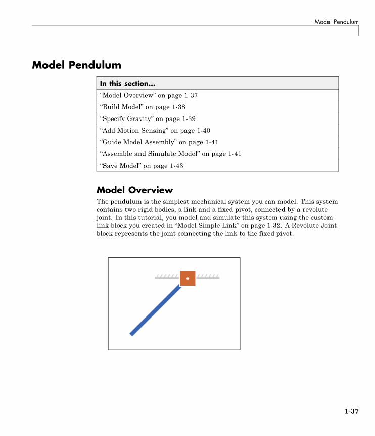
Model OverviewThe pendulum is the simplest mechanical system you can model. This systemcontains two rigid bodies, a link and a fixed pivot, connected by a revolutejoint. In this tutorial, you model and simulate this system using the customlink block you created in “Model Simple Link” on page 1-32. A Revolute Jointblock represents the joint connecting the link to the fixed pivot.
1-37
1 Introduction to SimMechanics™ Software
Build Model
1 At the MATLAB command line, enter smnew. The SimMechanics blocklibrary and a new model open up.
2 In the model, delete all blocks except Solver Configuration, World Frame,and Mechanism Configuration.
3 Drag the custom Link block into the model.
This is the block you created in the tutorial “Model Simple Link” on page1-32.
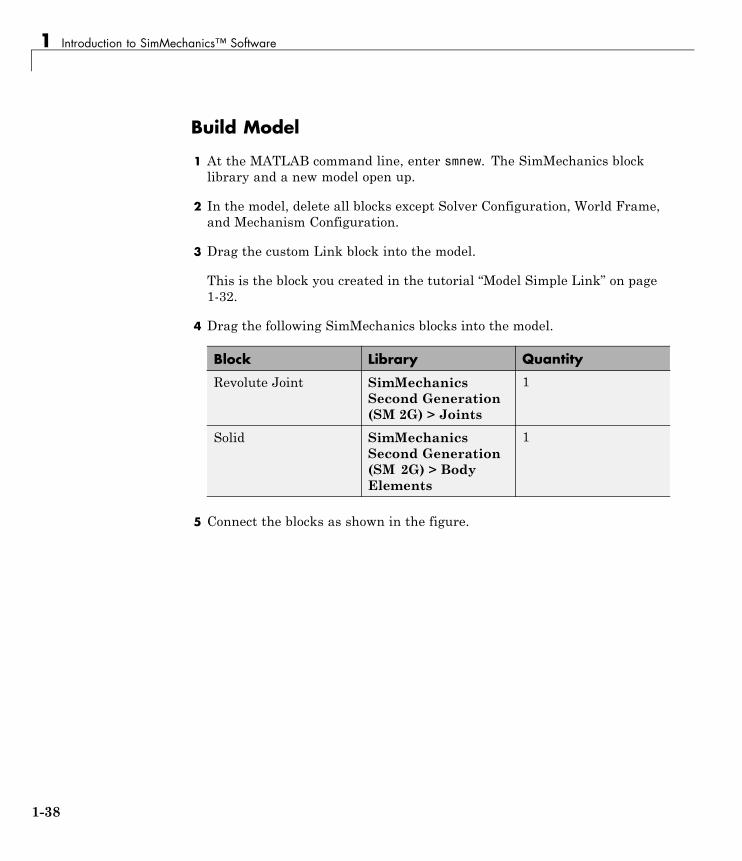
4 Drag the following SimMechanics blocks into the model.
Block Library Quantity
Revolute Joint SimMechanicsSecond Generation(SM 2G) > Joints
1
Solid SimMechanicsSecond Generation(SM 2G) > BodyElements
1
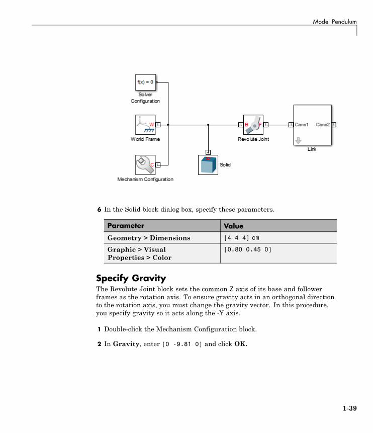
5 Connect the blocks as shown in the figure.
1-38
Model Pendulum
6 In the Solid block dialog box, specify these parameters.
Parameter Value
Geometry > Dimensions [4 4 4] cm
Graphic > VisualProperties > Color
[0.80 0.45 0]
Specify GravityThe Revolute Joint block sets the common Z axis of its base and followerframes as the rotation axis. To ensure gravity acts in an orthogonal directionto the rotation axis, you must change the gravity vector. In this procedure,you specify gravity so it acts along the -Y axis.
1 Double-click the Mechanism Configuration block.
2 In Gravity, enter [0 -9.81 0] and click OK.
1-39
1 Introduction to SimMechanics™ Software
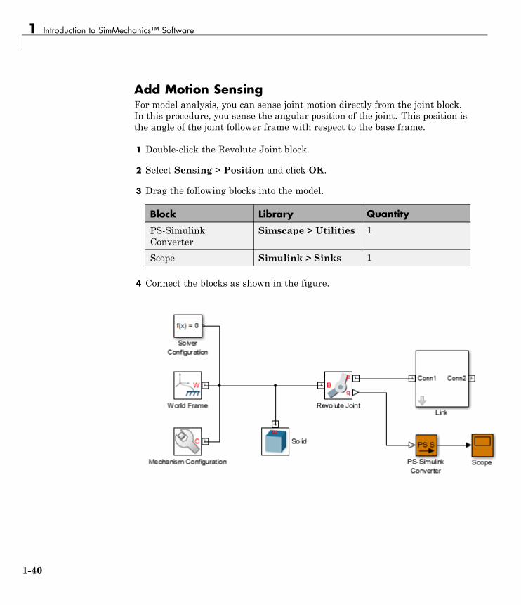
Add Motion SensingFor model analysis, you can sense joint motion directly from the joint block.In this procedure, you sense the angular position of the joint. This position isthe angle of the joint follower frame with respect to the base frame.
1 Double-click the Revolute Joint block.
2 Select Sensing > Position and click OK.
3 Drag the following blocks into the model.
Block Library Quantity
PS-SimulinkConverter
Simscape > Utilities 1
Scope Simulink > Sinks 1
4 Connect the blocks as shown in the figure.
1-40
Model Pendulum
Guide Model AssemblySet the initial angle at the revolute joint between the link and the fixed pivot.
1 Double-click the Revolute Joint block.
2 Select State Targets > Specify Position Target.
3 In Value, enter -60 and click OK.
Assemble and Simulate ModelIn the model window, press Ctrl+D. SimMechanics assembles the modelin its initial configuration. Mechanics Explorer displays a 3-D view of thisconfiguration with the Z axis pointing up. Since gravity acts along the -Y axis,it helps to change the view convention so the Y axis points up.
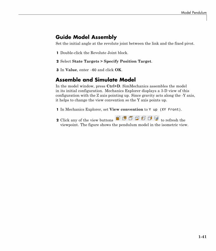
1 In Mechanics Explorer, set View convention to Y up (XY Front).
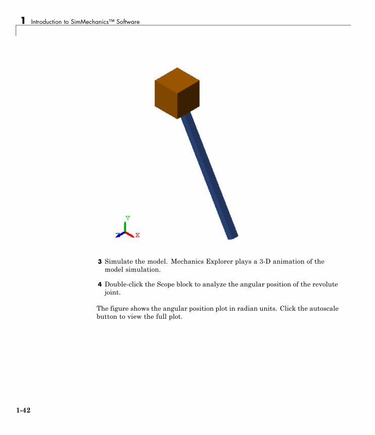
2 Click any of the view buttons to refresh theviewpoint. The figure shows the pendulum model in the isometric view.
1-41
1 Introduction to SimMechanics™ Software
3 Simulate the model. Mechanics Explorer plays a 3-D animation of themodel simulation.
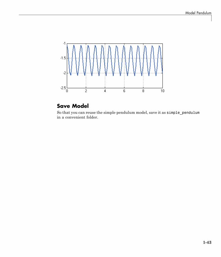
4 Double-click the Scope block to analyze the angular position of the revolutejoint.
The figure shows the angular position plot in radian units. Click the autoscalebutton to view the full plot.
1-42
Model Pendulum
Save ModelSo that you can reuse the simple pendulummodel, save it as simple_pendulumin a convenient folder.
1-43
1 Introduction to SimMechanics™ Software
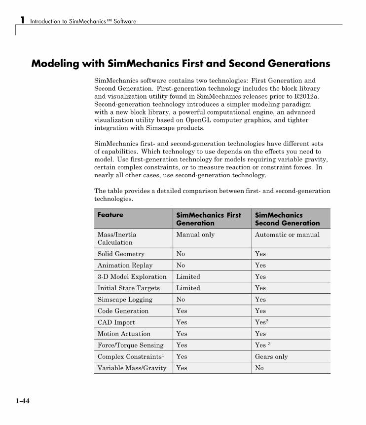
Modeling with SimMechanics First and Second GenerationsSimMechanics software contains two technologies: First Generation andSecond Generation. First-generation technology includes the block libraryand visualization utility found in SimMechanics releases prior to R2012a.Second-generation technology introduces a simpler modeling paradigmwith a new block library, a powerful computational engine, an advancedvisualization utility based on OpenGL computer graphics, and tighterintegration with Simscape products.
SimMechanics first- and second-generation technologies have different setsof capabilities. Which technology to use depends on the effects you need tomodel. Use first-generation technology for models requiring variable gravity,certain complex constraints, or to measure reaction or constraint forces. Innearly all other cases, use second-generation technology.
The table provides a detailed comparison between first- and second-generationtechnologies.
Feature SimMechanics FirstGeneration
SimMechanicsSecond Generation
Mass/InertiaCalculation
Manual only Automatic or manual
Solid Geometry No Yes
Animation Replay No Yes
3-D Model Exploration Limited Yes
Initial State Targets Limited Yes
Simscape Logging No Yes
Code Generation Yes Yes
CAD Import Yes Yes2
Motion Actuation Yes Yes
Force/Torque Sensing Yes Yes 3
Complex Constraints1 Yes Gears only
Variable Mass/Gravity Yes No
1-44
Modeling with SimMechanics™ First and Second Generations
1Point-curve, Gear, Velocity, and Screw constraints
2CAD update supported only in SimMechanics First Generation
3Actuation forces/torques only
SimMechanics continues to support first-generation technology. You canmaintain and simulate legacy models built with first-generation blocks. Youalso can still create a new first-generation model using the SimMechanicsFirst Generation block library.
1-45