Embed Size (px)
Citation preview

User Manual 08/2003 Edition
simodrive
POSMO Distributeon PROF
A d Positioning Motor IBUS-DP


Valid for
Unit Software versionSIMODRIVE POSMO A– 75 W motor Version M (2.0)– 300 W motor Version E (2.0)
08.03 Edition
Distributed Positioning Motoron PROFIBUS DP
SIMODRIVE POSMO A
User ManualUser ManualUser ManualUser ManualUser ManualUser ManualUser ManualUser ManualUser ManualUser ManualUser ManualUser ManualUser Manual
Brief Description 1
Installing andConnecting–Up 2
Start–Up 3
Communications viaPROFIBUS-DP 4
Description of theFunctions 5
Fault Handling andDiagnostics 6
Installation and Service 7
List of Abbreviations A
References B
Dimension Drawings C
EC Declaration of Conformity D
Index E

SIMODRIVE documentation
Printing historyBrief details of this edition and previous editions are listed below.
The status of each edition is shown by the code in the ”Remarks” column.
Status code in the ”Remarks” column:
A.... New Documentation
B.... Unrevised reprint with new Order No.
C.... Revised edition with new status
If factual changes have been made on the page since the last edition, this is indicated by a newedition coding in the header on that page.
Edition Order No. Remarks
02.99 6SN2197–0AA00–0BP0 A
02.00 6SN2197–0AA00–0BP1 C
04.01 6SN2197–0AA00–0BP2 C
08.01 6SN2197–0AA00–0BP3 C
08.02 6SN2197–0AA00–0BP4 C
05.03 6SN2197–0AA00–0BP5 C
08.03 6SN2197–0AA00–0BP6 C
This manual is included in the documentation available on CD-ROM (DOCONCD)Edition Order No. Remark03.04 6FC5 298–7CA00–0BG0 C
TrademarksSIMATIC�, SIMATIC HMI�, SIMATIC NET�, SIROTEC�, SINUMERIK�, SIMODRIVE� and SIMODRIVEPOSMO� are Siemens trademarks. All other product and system names are registered trademarks of theirrespective owners and must be treated accordingly.
Additional information is available in the Internet under:http://www.ad.siemens.de/mc
This documentation was produced with Interleaf V 7
The reproduction, transmission or use of this document or its contents isnot permitted without express written authorization. Offenders will be liablefor damages. All rights, including rights created by patent grant orregistration of a utility model or design, are reserved.
Siemens AG 2003 All rights reserved.
Other functions not described in this documentation might be executable inthe control. This does not, however, represent an obligation to supply suchfunctions with a new control or when servicing.
We have checked the contents of this document to ensure that theycoincide with the described hardware and software. Nonetheless,differences might exist and therefore we cannot guarantee that they arecompletely identical. The information in this document is regularly checkedand necessary corrections are included in reprints. Suggestions forimprovement are welcome at all times.
Subject to change without prior notice.
Siemens–AktiengesellschaftOrder No.6SN2197–0AA00–0BP6Printed in the Federal Republic of Germany
3ls
v� Siemens AG 2003 All rights reservedSIMODRIVE POSMO A User Manual (POS1) – 08.03 Edition
Foreword
Instructions when reading
The SIMODRIVE documentation is subdivided into the following levels:
� General Documentation/Catalogs
� Manufacturer/Service Documentation
� Electronic Documentation
You can obtain more detailed information on the documents listed inthe documentation overview as well as additional SIMODRIVE docu-mentation from your local Siemens office.
This manual does not purport to cover all details or variations in equip-ment, nor to provide for every possible contingency to be met in con-nection with installation, operation or maintenance.
The contents of this document are not part of an earlier or existing con-tract or agreement nor do they change this.
The sales contract contains the entire obligation of Siemens. The war-ranty conditions specified in the contract between the parties is the solewarranty of Siemens.
Any statements contained herein neither create new warranties normodify the existing warranty.
This documentation addresses machine manufacturers and servicepersonnel who use the SIMODRIVE POSMO A positioning motor.
If you have any questions, please contact the following Hotline:
A&D Technical Support Tel.: +49 (0) 180 5050 – 222Fax: +49 (0) 180 5050 – 223email: [email protected]
If you have any questions regarding the documentation (suggestions,corrections), please send a fax or email:
Fax: +49 (0) 9131/98 – 2176Fax form Refer to the correction sheet at the end of the documentationemail: [email protected]
You can obtain continually updated information about our product in theInternet under:
http://www.ad.siemens.de
You will find the certificates for the products described in this documen-tation under: http://intra1.erlf.siemens.de/qm/home/index.html
This User Manual provides detailed information about the functionalscope of the SIMODRIVE POSMO A positioning motor.
Structure of thedocumentation
Target group
Technical Support
Internet address
Certificates
Goal

vi� Siemens AG 2003 All rights reserved
SIMODRIVE POSMO A User Manual (POS1) – 08.03 Edition
Should further information be desired or should particular problemsarise, which are not covered sufficiently for the purchaser’s purposes,the matter should be referred to the local Siemens sales office.
The following should be observed when using this manual:
1. Help: The following help is available for the reader:
� Complete table of contents
� Header line (as orientation):
the main chapter is in the upper header linethe sub–chapter is in the lower header line
� Appendix with
– Abbreviations and List of References
– Index
If you require information on a specific term, look in the Appendixunder ”Index” for this term.
The Chapter number as well as the page number is specifiedwhere information on this term can be found.
2. Identifying ”new” or ”revised” information
The documentation 02.99 edition is the first edition.
How is the ”new” or ”revised” information identified for the othereditions?
� This is specified directly next to the information ”from SW x.y”.
� The edition is in the header line on the respective page > 02.99.
3. Notation
� � means ”corresponds to”
� Numerical representation (examples)
– FFFFhex Hexadecimal number
– 0101bin Binary number
– 100dec Decimal number
� PROFIBUS signals (examples)
– STW.3 Control word bit 3
– ZSW.11 Status word bit 11
� Parameter (examples)
– P10 Parameter 10 without index
– P82:28 Parameter 82 mit Index 0, 1, ... 27 (28 indices)
– P82:13 Parameter 82 with index 13
– P82:x Parameter with undefined index x
– P56.2 Parameter 56 bit 2
Information aboutusing this manual
Foreword

vii� Siemens AG 2003 All rights reservedSIMODRIVE POSMO A User Manual (POS1) – 08.03 Edition
There is a fixed relationship between the edition of the documentationand positioning motor software release.
� The first edition 02.99 describes the functionality of SW 1.0.
� The 02.00 edition describes the functionality of SW 1.0 to 1.2.
What are the essential new functions for SW 1.2 in comparison toSW 1.0?
– Run up mode can be set when the unit is powered up again (P56)
– Stand-alone operation (without bus communications, P100, P101)
– Suppress block
– Program stop via traversing block
– Set actual position via traversing block
� The 04.01 edition describes the functionality of SW 1.0 to 1.5.
What are the essential new functions for SW 1.3 in comparison toSW 1.2?
– Rotary axis: Signal position with modulo evaluation
– Direction of rotation of the motor shaft can be reversed (P3)
– Holding controller (P56.2, P57)
– Status bit ZSW.15: Modified behavior
– Behavior when shutting down supplemented
– FB 12 ”PARAMETERIZE_ALL_POSMO_A” (from 05.00)
Reading and writing the parameter set of a drive
What are the essential new functions for SW 1.4 in comparison toSW 1.3?
– Worm gear SG 75
– Resetting the ”reference point set” status via P98
– Checkback signal, status of the input/output terminals 1 and 2
– Brake sequence control
– Additional diagnostics via P954
– Jogging without PROFIBUS and parameterization
– Backlash compensation with correction direction
– Flying measurement/actual value setting
What are the essential new functions for SW 1.5 in comparison toSW 1.4?
– First software for 300 W motors
– Shared software for 75 W and 300 W motors
– Different union nuts for the connection cover for 75 W and 300 Wmotors.
– ”SimoCom A” parameterizing and start–up tool
– PROFIBUS: Initiating a POWER ON–RESET via P97
Edition of thedocumentation?
Software release?
What is new?
Foreword

viii� Siemens AG 2003 All rights reserved
SIMODRIVE POSMO A User Manual (POS1) – 08.03 Edition
� The 08.01 edition describes the functionality of SW 1.0 to 1.5.
– This edition contains troubleshooting information and updateswhich have been obtained since the 04.01 edition.
� The 08.02 edition describes the functionality of SW 1.0 to 1.6.
– This edition contains troubleshooting information and updateswhich have been obtained since the 08.01 edition:
� The 05.03 edition describes the functionality of SW 1.0 to 2.0.
– This edition contains troubleshooting information and updateswhich have been obtained since the 08.02 edition.
What are the essential new functions for SW 2.0 in comparison toSW 1.6?
– Speed setpoint interface
– Choice of positioning or speed setpoint operating mode (P700)
– Hardware limit switch
� The 08.03 edition describes the functionality of SW 1.0 to 2.0.
– This edition contains troubleshooting information and updateswhich have been obtained since the 05.03 edition.
– The same connection union for connection covers for 75 W and300 W motors.
The following inter–relationships exist between the version of thepositioning motor, drive software release, motor type and SimoCom A:
Table 1-1 Version, software release, motor type, SimoCom A
Motor version(stamped on the motor)
Softwarerelease
Using SimoCom A
75 W motor 300 W motor 75 W motor 300 W motor can bereplaced
Version
A – 1.0 Yes No No –
B – 1.1 Yes No No –
C – 1.1 Yes No No –
D – 1.2 Yes No No –
E – 1.2 Yes No No –
F – 1.3 Yes No No –
G, H A 1.4 Yes Yes No –
J, K B, C 1.5 Yes Yes Yes 1.0, 2.0, 3.0
L D 1.6 Yes Yes Yes 3.0
M E 2.0 Yes Yes Yes 4.0
Information about the positioning motor can be read from the following parameters:P0052 HW versionP0053 SW versionP0964 (from SW 1.4) Device identification (refer to Section 5.6.2)
Motor version,software release,motor type,SimoCom A
Foreword

ix� Siemens AG 2003 All rights reservedSIMODRIVE POSMO A User Manual (POS1) – 08.03 Edition
Qualified personnel, in the sense of this document and the warninginformation on the product itself, are those personnel who are suitablytrained and qualified to erect, install, commission and operate products,for example:e.g.:
� Trained and authorized to energize, de–energize, clear, ground andtag circuits and equipment in accordance with established safetyprocedures.
� Trained in the proper care and use of protective equipment in accor-dance with established safety procedures.
� Trained in rendering first aid
The following symbols are used in this documentation:
!Danger
This symbol is used in the document to indicate that death, severepersonal injury or substantial property damage will result if properprecautions are not taken.
!Warning
This symbol is used in the document to indicate that death, severepersonal injury or property damage can result if proper precautions arenot taken.
!Caution
This symbol is used in the document to indicate that minor personalinjury or material damage can result if proper precautions are nottaken.
Caution
This warning (without warning triangle) indicates that material damagecan result if proper precautions are not taken.
Definition:Who arequalifiedpersonnel?
Explanation-of the symbols
Foreword

x� Siemens AG 2003 All rights reserved
SIMODRIVE POSMO A User Manual (POS1) – 08.03 Edition
Notice
This warning indicates that an undesirable situation or condition canoccur if the appropriate instructions/information are not observed.
Note
This symbol indicates important information about the product or partof the document, where the reader should take special note.
Reader’s note
This symbol is shown, if it relates to important information which thereader must observe.
Technical information
!Warning
Operational electrical equipment has parts and components which areat hazardous voltage levels.
Incorrect handling of these units, i.e. not observing the warninginformation, can therefore lead to death, severe bodily injury orsignificant material damage.
Only appropriately qualified personnel may commission/start up thisequipment.
This personnel must have in–depth knowledge regarding all of thewarning information and service measures according to this manual.
Perfect, safe and reliable operation of the equipment assumes that ithas been professionally transported, stored, mounted and installed aswell as careful operator control and service.
Hazardous axis motion can occur when working with the equipment.
Foreword

xi� Siemens AG 2003 All rights reservedSIMODRIVE POSMO A User Manual (POS1) – 08.03 Edition
Note
When handling cables, observe the following:
� They may not be damaged,
� They may not be stressed,
� They must not come into contact with rotating components.
!Warning
When testing the voltage of the electrical equipment of the machineson the system side, all of the SIMODRIVE drive unit connections mustbe withdrawn or disconnected (EN 60204–1 (VDE 0113–1), Pt. 20.4).
This is necessary, as the SIMODRIVE insulation has already beentested, and should not be subject to a new test (additional voltagestressing).
!Warning
Start–up/commissioning is absolutely prohibited until it has beenensured that the machine in which the components described here areto be installed, fulfills the regulations/specifications of the Directive98/37/EC.
!Warning
The information and instructions in all of the documentation suppliedand any other instructions must always be observed to eliminatehazardous situations and damage.
� For special versions of the machines and equipment, theinformation in the associated catalogs and quotations applies.
� Further, all of the relevant national, local land plant/system–specificregulations and specifications must be taken into account.
� All work should be undertaken with the system in a no–voltagecondition!
Caution
When using mobile radio equipment (e.g. cellular phones,walkie–talkies) with a transmitting power of > 1 W close to SIMODRIVE POSMO A (< 1.5 m), this can have a negative impact onthe functioning of the SIMODRIVE POSMO A.
Foreword

xii� Siemens AG 2003 All rights reserved
SIMODRIVE POSMO A User Manual (POS1) – 08.03 Edition
ElectroStatic Discharge Sensitive Devices
Note
Components, which can be destroyed by electrostatic discharge areindividual components, integrated circuits, or boards, which whenhandled, tested, or transported, could be destroyed by electrostaticfields or electrostatic discharge. ESDS (ElectroStatic Discharge Sensitive Devices).
Handling ESDS boards:
� When handling devices which can be destroyed by electrostaticdischarge, personnel, workstations and packaging must be wellgrounded!
� Electronic boards should only be touched when absolutelynecessary.
� Personnel may only come into contact with the components, if
– they are continuously grounded through ESDS wristlets,
– they wear ESDS shoes, ESDS shoe grounding strips inconjunction with an ESDS floor surface.
� Boards may only be placed on conductive surfaces (table withESDS surface, conductive ESDS foam rubber, ESDS packing bag,ESDS transport containers).
� Boards may not be brought close to data terminals, monitors ortelevision sets (minimum clearance to the screen > 10 cm).
� Boards may not be brought into contact with highly insulatingmaterials which can be statically charged, e.g. plastic foils,insulating desktops, clothing manufactured from man–made fibers
� Measuring work may only be carried out on the boards, if
– the measuring unit is grounded (e.g. via protective conductor),or
– for floating measuring equipment, the probe is briefly dischargedbefore making measurements (e.g. a bare–metal controlhousing is touched).
� Only touch control boards, option modules and memory modules atthe front panel or at the edge of the PC boards.
ESDS instructions
Foreword
xiii� Siemens AG 2003 All rights reservedSIMODRIVE POSMO A User Manual (POS1) – 08.03 Edition
Table of Contents
1 Brief Description 1-17. . . . . . . . . . . . . . . . . . . . . . . . . . . . . . . . . . . . . . . . . . . . . . . . . . . . . .
1.1 General information about SIMODRIVE POSMO A 1-17. . . . . . . . . . . . . . . . .
1.2 Function overview and differences between 75 W / 300 W 1-20. . . . . . . . . . .
1.3 Safety–related information 1-22. . . . . . . . . . . . . . . . . . . . . . . . . . . . . . . . . . . . . . .
2 Installing and Connecting–up 2-25. . . . . . . . . . . . . . . . . . . . . . . . . . . . . . . . . . . . . . . . . .
2.1 System overview of SIMODRIVE POSMO A 2-25. . . . . . . . . . . . . . . . . . . . . . .
2.2 Electrical system requirements 2-26. . . . . . . . . . . . . . . . . . . . . . . . . . . . . . . . . . . 2.2.1 General electrical requirements 2-26. . . . . . . . . . . . . . . . . . . . . . . . . . . . . . . . . . . 2.2.2 DC power supply (24 V, 48 V) 2-27. . . . . . . . . . . . . . . . . . . . . . . . . . . . . . . . . . . . . 2.2.3 Regenerative feedback protection when the motor brakes 2-33. . . . . . . . . . . .
2.3 Connection and wiring overview 2-37. . . . . . . . . . . . . . . . . . . . . . . . . . . . . . . . . . 2.3.1 Connection and setting possibilities in the connection cover 2-38. . . . . . . . . . . 2.3.2 Protective grounding and potential bonding 2-44. . . . . . . . . . . . . . . . . . . . . . . . .
2.4 Mounting SIMODRIVE POSMO A 2-45. . . . . . . . . . . . . . . . . . . . . . . . . . . . . . . . 2.4.1 Mounting overview 2-45. . . . . . . . . . . . . . . . . . . . . . . . . . . . . . . . . . . . . . . . . . . . . . 2.4.2 Preparing the cable 2-46. . . . . . . . . . . . . . . . . . . . . . . . . . . . . . . . . . . . . . . . . . . . . . 2.4.3 Mounting the prepared cables in the connection cover 2-49. . . . . . . . . . . . . . . .
2.5 Gearbox selection 2-52. . . . . . . . . . . . . . . . . . . . . . . . . . . . . . . . . . . . . . . . . . . . . . 2.5.1 Gearboxes for SIMODRIVE POSMO A –75 W 2-52. . . . . . . . . . . . . . . . . . . . . . 2.5.2 Gearboxes for SIMODRIVE POSMO A – 300 W 2-53. . . . . . . . . . . . . . . . . . . . .
2.6 Technical data 2-54. . . . . . . . . . . . . . . . . . . . . . . . . . . . . . . . . . . . . . . . . . . . . . . . . 2.6.1 Technical data for SIMODRIVE POSMO A –75 W 2-54. . . . . . . . . . . . . . . . . . . 2.6.2 Technical data for SIMODRIVE POSMO A – 300 W 2-58. . . . . . . . . . . . . . . . . .
3 Start–up 3-63. . . . . . . . . . . . . . . . . . . . . . . . . . . . . . . . . . . . . . . . . . . . . . . . . . . . . . . . . . . . . .
3.1 General information on start–up 3-63. . . . . . . . . . . . . . . . . . . . . . . . . . . . . . . . . .
3.2 Commissioning the DP master 3-65. . . . . . . . . . . . . . . . . . . . . . . . . . . . . . . . . . . 3.2.1 Commissioning and communications for the master 3-65. . . . . . . . . . . . . . . . . . 3.2.2 SIMATIC S7 function blocks 3-68. . . . . . . . . . . . . . . . . . . . . . . . . . . . . . . . . . . . . . 3.2.3 Parameterizing and start–up tool ”SimoCom A” (from SW 1.5) 3-69. . . . . . . . . 3.2.4 Parameterizing and start–up tool C1 master ”SIMODRIVE POSMO A
PROFIBUS MASTER” 3-78. . . . . . . . . . . . . . . . . . . . . . . . . . . . . . . . . . . . . . . . . . .
3.3 Commissioning an axis 3-80. . . . . . . . . . . . . . . . . . . . . . . . . . . . . . . . . . . . . . . . . . 3.3.1 Control structure positioning (pos mode) 3-83. . . . . . . . . . . . . . . . . . . . . . . . . . . . 3.3.2 Control structure, speed setpoint (n–set mode) 3-84. . . . . . . . . . . . . . . . . . . . . . 3.3.3 Flow diagram to commission a SIMODRIVE POSMO A 3-85. . . . . . . . . . . . . . 3.3.4 Optimization runs 3-87. . . . . . . . . . . . . . . . . . . . . . . . . . . . . . . . . . . . . . . . . . . . . . .

xiv� Siemens AG 2003 All rights reserved
SIMODRIVE POSMO A User Manual (POS1) – 08.03 Edition
4 Communications via PROFIBUS–DP 4-89. . . . . . . . . . . . . . . . . . . . . . . . . . . . . . . . . . . .
4.1 General information about PROFIBUS DP 4-89. . . . . . . . . . . . . . . . . . . . . . . . .
4.2 Process data (PZD area) 4-93. . . . . . . . . . . . . . . . . . . . . . . . . . . . . . . . . . . . . . . . 4.2.1 Description of the control signals (data to drive) 4-94. . . . . . . . . . . . . . . . . . . . . 4.2.2 Description of the status signals (data from the drive) 4-100. . . . . . . . . . . . . . . . 4.2.3 Example: Operating the drive via the control signals with jogging 1 4-106. . . . . 4.2.4 Example: The drive should traverse with n–set using the control signals 4-1074.2.5 ”Variable–speed drives” flow diagram 4-108. . . . . . . . . . . . . . . . . . . . . . . . . . . . . .
4.3 Parameter area (PKW area) 4-111. . . . . . . . . . . . . . . . . . . . . . . . . . . . . . . . . . . . . 4.3.1 Structure and description of the parameter area 4-111. . . . . . . . . . . . . . . . . . . . . 4.3.2 Example: Reading parameters via PROFIBUS 4-116. . . . . . . . . . . . . . . . . . . . . . 4.3.3 Example: Writing parameters via PROFIBUS 4-118. . . . . . . . . . . . . . . . . . . . . . .
4.4 Settings at the PROFIBUS DP master 4-120. . . . . . . . . . . . . . . . . . . . . . . . . . . . 4.4.1 General information on the DP master 4-120. . . . . . . . . . . . . . . . . . . . . . . . . . . . . 4.4.2 Installing the new master device files (GSD) 4-122. . . . . . . . . . . . . . . . . . . . . . . . 4.4.3 Operating the slave with a third–party master 4-122. . . . . . . . . . . . . . . . . . . . . . .
5 Description of Functions 5-123. . . . . . . . . . . . . . . . . . . . . . . . . . . . . . . . . . . . . . . . . . . . . . .
5.1 Operating mode (from SW 2.0) 5-123. . . . . . . . . . . . . . . . . . . . . . . . . . . . . . . . . . .
5.2 ”Speed setpoint” mode (P700 = 1) (from SW 2.0) 5-125. . . . . . . . . . . . . . . . . . . 5.2.1 General information on the ”speed setpoint” mode 5-125. . . . . . . . . . . . . . . . . . . 5.2.2 Ramp–function generator 5-126. . . . . . . . . . . . . . . . . . . . . . . . . . . . . . . . . . . . . . . . . 5.2.3 Direction of rotation reversal 5-128. . . . . . . . . . . . . . . . . . . . . . . . . . . . . . . . . . . . . . 5.2.4 Display of the position actual value 5-128. . . . . . . . . . . . . . . . . . . . . . . . . . . . . . . . 5.2.5 Adaptation of the speed controller 5-128. . . . . . . . . . . . . . . . . . . . . . . . . . . . . . . . . 5.2.6 Parameters for the n-set mode 5-129. . . . . . . . . . . . . . . . . . . . . . . . . . . . . . . . . . . . 5.2.7 Terminal signals 5-129. . . . . . . . . . . . . . . . . . . . . . . . . . . . . . . . . . . . . . . . . . . . . . . . .
5.3 Programming the traversing blocks (only in the pos mode, P700 = 2) 5-130. . 5.3.1 Overview of the traversing blocks and programs 5-130. . . . . . . . . . . . . . . . . . . . . 5.3.2 Structure and description of the traversing blocks 5-133. . . . . . . . . . . . . . . . . . . . 5.3.3 Selecting and controlling traversing blocks and programs 5-139. . . . . . . . . . . . .
5.4 Operating modes (only the pos mode) 5-140. . . . . . . . . . . . . . . . . . . . . . . . . . . . . 5.4.1 Jogging 5-140. . . . . . . . . . . . . . . . . . . . . . . . . . . . . . . . . . . . . . . . . . . . . . . . . . . . . . . . 5.4.2 Manual Data Input (MDI) 5-141. . . . . . . . . . . . . . . . . . . . . . . . . . . . . . . . . . . . . . . . . 5.4.3 Automatic 5-141. . . . . . . . . . . . . . . . . . . . . . . . . . . . . . . . . . . . . . . . . . . . . . . . . . . . . . 5.4.4 Tracking mode 5-141. . . . . . . . . . . . . . . . . . . . . . . . . . . . . . . . . . . . . . . . . . . . . . . . . .
5.5 SIMODRIVE POSMO A functions 5-142. . . . . . . . . . . . . . . . . . . . . . . . . . . . . . . . 5.5.1 Referencing 5-142. . . . . . . . . . . . . . . . . . . . . . . . . . . . . . . . . . . . . . . . . . . . . . . . . . . . 5.5.2 Flying measurement/actual value setting (from SW 1.4) 5-151. . . . . . . . . . . . . . 5.5.3 Traversing to a fixed endstop 5-158. . . . . . . . . . . . . . . . . . . . . . . . . . . . . . . . . . . . . 5.5.4 Rotary axis 5-159. . . . . . . . . . . . . . . . . . . . . . . . . . . . . . . . . . . . . . . . . . . . . . . . . . . . . 5.5.5 Backlash compensation and correction direction (from SW 1.4) 5-161. . . . . . . . 5.5.6 Jerk limiting 5-163. . . . . . . . . . . . . . . . . . . . . . . . . . . . . . . . . . . . . . . . . . . . . . . . . . . . 5.5.7 Changeover, metric/inch 5-164. . . . . . . . . . . . . . . . . . . . . . . . . . . . . . . . . . . . . . . . . . 5.5.8 Reversing the control sense (from SW 1.3) 5-164. . . . . . . . . . . . . . . . . . . . . . . . . 5.5.9 Standstill monitoring 5-165. . . . . . . . . . . . . . . . . . . . . . . . . . . . . . . . . . . . . . . . . . . . . 5.5.10 Digital inputs/outputs 5-166. . . . . . . . . . . . . . . . . . . . . . . . . . . . . . . . . . . . . . . . . . . . . 5.5.11 Jogging without PROFIBUS and parameterization (from SW 1.4) 5-168. . . . . . 5.5.12 Standalone mode (without bus communications) (from SW 1.2) 5-169. . . . . . . .
Table of Contents

xv� Siemens AG 2003 All rights reservedSIMODRIVE POSMO A User Manual (POS1) – 08.03 Edition
5.5.13 Holding brake (from SW 1.4) 5-171. . . . . . . . . . . . . . . . . . . . . . . . . . . . . . . . . . . . . . 5.5.14 Limit switch monitoring functions 5-178. . . . . . . . . . . . . . . . . . . . . . . . . . . . . . . . . .
5.6 Parameters for SIMODRIVE POSMO A 5-181. . . . . . . . . . . . . . . . . . . . . . . . . . . 5.6.1 General information on parameters 5-181. . . . . . . . . . . . . . . . . . . . . . . . . . . . . . . . 5.6.2 List of parameters 5-183. . . . . . . . . . . . . . . . . . . . . . . . . . . . . . . . . . . . . . . . . . . . . . . 5.6.3 Gearbox–dependent parameters, factory defaults 5-210. . . . . . . . . . . . . . . . . . . .
6 Fault Handling and Diagnostics 6-213. . . . . . . . . . . . . . . . . . . . . . . . . . . . . . . . . . . . . . . .
6.1 LED fault display 6-213. . . . . . . . . . . . . . . . . . . . . . . . . . . . . . . . . . . . . . . . . . . . . . .
6.2 Faults and warnings 6-214. . . . . . . . . . . . . . . . . . . . . . . . . . . . . . . . . . . . . . . . . . . . 6.2.1 General information on faults and warnings 6-214. . . . . . . . . . . . . . . . . . . . . . . . . 6.2.2 List of faults and warnings 6-217. . . . . . . . . . . . . . . . . . . . . . . . . . . . . . . . . . . . . . . .
6.3 Analog test outputs 6-228. . . . . . . . . . . . . . . . . . . . . . . . . . . . . . . . . . . . . . . . . . . . .
6.4 Bus monitor AMPROLYZER for PROFIBUS DP 6-230. . . . . . . . . . . . . . . . . . . .
7 Installation and Service 7-231. . . . . . . . . . . . . . . . . . . . . . . . . . . . . . . . . . . . . . . . . . . . . . . .
7.1 Replacing the motor 7-231. . . . . . . . . . . . . . . . . . . . . . . . . . . . . . . . . . . . . . . . . . . .
7.2 Mounting or replacing a gearbox (only relevant for 300 W motors) 7-233. . . .
7.3 Spare parts for SIMODRIVE POSMO A 7-235. . . . . . . . . . . . . . . . . . . . . . . . . . . 7.3.1 List of spare parts for the 300 W motors 7-235. . . . . . . . . . . . . . . . . . . . . . . . . . . . 7.3.2 Drive unit as spare part (only the 300 W motor) 7-236. . . . . . . . . . . . . . . . . . . . . .
A Abbreviations A-239. . . . . . . . . . . . . . . . . . . . . . . . . . . . . . . . . . . . . . . . . . . . . . . . . . . . . . . . .
B References B-243. . . . . . . . . . . . . . . . . . . . . . . . . . . . . . . . . . . . . . . . . . . . . . . . . . . . . . . . . . . .
C Dimension Drawings C-247. . . . . . . . . . . . . . . . . . . . . . . . . . . . . . . . . . . . . . . . . . . . . . . . . . .
C.1 Dimension drawings for SIMODRIVE POSMO A –75 W C-247. . . . . . . . . . . . .
C.2 Dimension drawings for SIMODRIVE POSMO A – 300 W C-251. . . . . . . . . . .
D EC Declaration of Conformity D-255. . . . . . . . . . . . . . . . . . . . . . . . . . . . . . . . . . . . . . . . . .
E Index E-259. . . . . . . . . . . . . . . . . . . . . . . . . . . . . . . . . . . . . . . . . . . . . . . . . . . . . . . . . . . . . . . . .
�
Table of Contents

xvi� Siemens AG 2003 All rights reserved
SIMODRIVE POSMO A User Manual (POS1) – 08.03 Edition
Table of Contents
Space for your notes

1
1-17� Siemens AG 2003 All rights reservedSIMODRIVE POSMO A User Manual (POS1) – 08.03 Edition
Brief Description
1.1 General information about SIMODRIVE POSMO A
SIMODRIVE POSMO A is an intelligent distributed positioning motorconnected as node to the PROFIBUS DP fieldbus.
SIMODRIVE POSMO A can be operated via PROFIBUS DP. Thismeans that all of the signals and data required to commission (start–up) and operate the drive and also to evaluate faults are transferred viaPROFIBUS.
Further, the positioning motor can be operated in the standalone mode.This means that in this case, bus communications are not required inorder to move the positioning motor
SIMODRIVE POSMO A - 75 W SIMODRIVE POSMO A - 300 W
not to scale
Fig. 1-1 SIMODRIVE POSMO A positioning motor with connection cover and gearbox
Reader’s note
The following catalog is available for SIMODRIVE POSMO A:
Reference: /KT654/ Catalog DA 65.4 � 2001
Intelligentpositioning motor
1

1
1.1 General information about SIMODRIVE POSMO A
1-18� Siemens AG 2003 All rights reserved
SIMODRIVE POSMO A User Manual (POS1) – 08.03 Edition
The main features are:
� Power module and complete motion control in the motor
� Coupled using a communication and power bus
� PROFIBUS DP Standard slave
� Positioning functionality which is easy to handle
� Modular gearbox system with different ratios
SIMODRIVE POSMO A can be used in almost all industry sectors,such as e.g.:
� For production machines in packaging, woodworking, glass, printing,plastics
� For machine tools and transfer lines
� In medical diagnostics – for example to move examination tablesand X–ray equipment
Here are two typical applications from many:
� Adjusting formats or endstops
� Setting process quantities (e.g. via valves)
The positioning motor is a 1–axis actuating drive with low envelopedimensions and compact power connection, drive converter powersection, closed–loop motor control, positioning control (open–loop),communication and bus connection on the motor.
A 24 V supply voltage for the 75 W motor and 48 V for the 300 Wmotor supply the drive power.
Reference: /KT101/ SITOP power, power suppliesCatalog
The motor can be equipped and operated without a gearbox or with agearbox from a modular gearbox system.
� 75 W motor: Modular gearbox system, refer to Chapter 2.5.1
� 300 W motor: Modular gearbox system, refer to Chapter 2.5.2
Standard cables are used for all connections.
Main features
Applications
Typicalapplications
Design
Gearbox selection
Cables
1 Brief Description 04.01

1
1.1 General information about SIMODRIVE POSMO A
1-19� Siemens AG 2003 All rights reservedSIMODRIVE POSMO A User Manual (POS1) – 08.03 Edition
The positioning motor can be traversed as follows:
� Traverse to an end position with a velocity and acceleration whichcan be overridden.
� Traverse through a distance in a direction with velocity and accele-ration which can be overridden.
� Traverse with a speed and acceleration which can be overridden,direction is defined by the sign, as long as a time of logic conditionis fulfilled.
� Traverse as soon as an additional time or logic condition is fulfilled.
� Traverse as long as a time or logic condition is fulfilled.
There are a total of 27 traversing blocks, which can be used as indivi-dual blocks or as program.
The traversing blocks are subdivided as follows:
Trav. block Use
� 1 and 2 Reserved for jogging
� 3 – 12 Individual traversing blocks
� 13 – 17 Program 1 (standard, can be freely parameterized)
� 18 – 22 Program 2 (standard, can be freely parameterized)
� 23 – 27 Program 3 (standard, can be freely parameterized)
This setting is used as standard. Blocks 3 to 27 can be freely used assingle blocks or programs.
The PROFIBUS–DP fieldbus allows fast, cyclic data transfer betweenthe individual DP slaves and the higher–level DP master.
DP masters include, for example:
� Central controller of SIMATIC S7
� Master–capable communication processes (e.g. CP 5613)
� Communications modules (e.g. CP 342–5)
� Standard masters from other manufacturers
Reference: /IKPI/ Industrial Communications andField Devices, Catalog
Local diagnostics using LEDs for Fault/Ready.
The DP master can read–out and evaluate positioning motor faults andwarnings via PROFIBUS.
Two freely parameterizable analog test outputs for measurementswhen service is required.
Traversingpossibilities(examples)
Traversing blocksand programs
Communications
Diagnostics
1 Brief Description04.01
1
1.2 Function overview and differences between 75 W / 300 W
1-20� Siemens AG 2003 All rights reserved
SIMODRIVE POSMO A User Manual (POS1) – 08.03 Edition
1.2 Function overview and differences between 75 W / 300 W
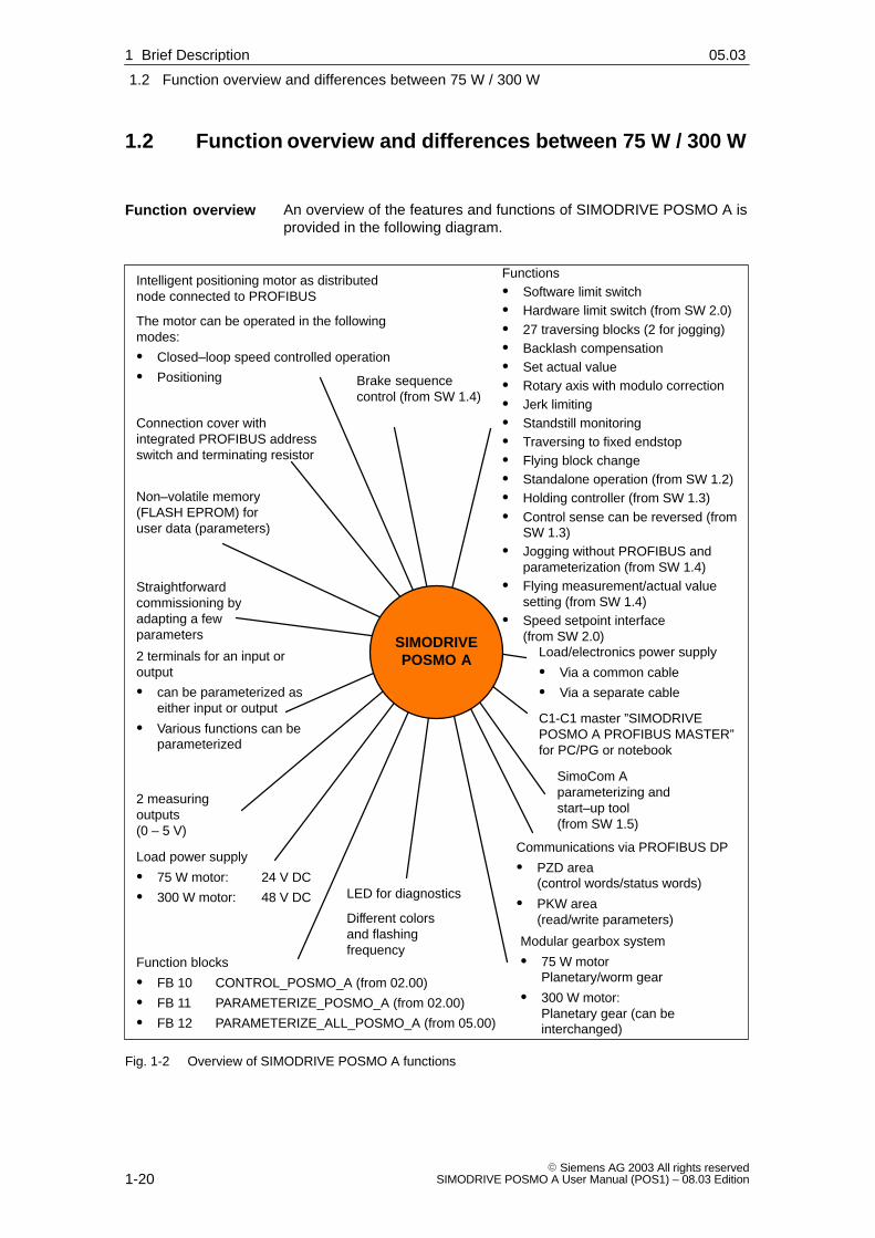
An overview of the features and functions of SIMODRIVE POSMO A isprovided in the following diagram.
2 terminals for an input oroutput
� can be parameterized aseither input or output
� Various functions can beparameterized
LED for diagnostics
Different colorsand flashingfrequency
Functions� Software limit switch� Hardware limit switch (from SW 2.0)� 27 traversing blocks (2 for jogging)� Backlash compensation� Set actual value� Rotary axis with modulo correction� Jerk limiting� Standstill monitoring� Traversing to fixed endstop� Flying block change� Standalone operation (from SW 1.2)� Holding controller (from SW 1.3)� Control sense can be reversed (from
SW 1.3)� Jogging without PROFIBUS and
parameterization (from SW 1.4)� Flying measurement/actual value
setting (from SW 1.4)� Speed setpoint interface
(from SW 2.0)
C1-C1 master ”SIMODRIVEPOSMO A PROFIBUS MASTER”for PC/PG or notebook
Communications via PROFIBUS DP
� PZD area(control words/status words)
� PKW area(read/write parameters)
Non–volatile memory(FLASH EPROM) foruser data (parameters)
2 measuringoutputs(0 – 5 V)
Intelligent positioning motor as distributednode connected to PROFIBUS
The motor can be operated in the followingmodes:
� Closed–loop speed controlled operation
� Positioning
Straightforwardcommissioning byadapting a fewparameters
Modular gearbox system
� 75 W motor Planetary/worm gear
� 300 W motor: Planetary gear (can beinterchanged)
Load/electronics power supply
� Via a common cable
� Via a separate cable
Function blocks
� FB 10 CONTROL_POSMO_A (from 02.00)
� FB 11 PARAMETERIZE_POSMO_A (from 02.00)
� FB 12 PARAMETERIZE_ALL_POSMO_A (from 05.00)
Connection cover withintegrated PROFIBUS addressswitch and terminating resistor
Brake sequencecontrol (from SW 1.4)
SIMODRIVEPOSMO A
Load power supply
� 75 W motor: 24 V DC
� 300 W motor: 48 V DC
SimoCom Aparameterizing andstart–up tool(from SW 1.5)
Fig. 1-2 Overview of SIMODRIVE POSMO A functions
Function overview
1 Brief Description 04.0105.03

1
1.2 Function overview and differences between 75 W / 300 W
1-21� Siemens AG 2003 All rights reservedSIMODRIVE POSMO A User Manual (POS1) – 08.03 Edition
There are the following basic differences between POSMO A with 75 Wand POSMO A with 300 W:
Table 1-1 Difference: POSMO A with 75 W and 300 W
SIMODRIVE POSMO A
Designation 75 W 300 W
Order No. (MLFB) 6SN2 132-���11-1BA0 6SN2 155-���xy-1BA0x = 1 ––> Motor/drive unit IP64
Gearbox IP54x = 2 ––> Degree of protection IP65y = 1 ––> with motor holding brakey = 0 ––> without motor holding brake
Software all available versions possible from version A (SW 1.5)
Supply voltages 24 V DC �20 % 48 V DC �20 %
Rated output 62.5 W(S1)
75 W(S3, 25 %, 1 min)
176 W(S1)
300 W(S3, 25 %, 4 min)
Rated speed 3,300 RPM(S1)
2,000 RPM(S3, 25 %, 1 min)
3,500 RPM(S1)
3,000 RPM(S3, 25 %, 4 min)
Rated torque 0.18 Nm (S1)
0.36 Nm (S3, 25 %, 1 min)
0.48 Nm (S1)
0.95 Nm (S3, 25 %, 4 min)
Measuring system integrated
816 increments/motor revolution
integrated
4096 increments/motor revolution
Gearbox without gearboxPlanetary gearbox 1–stagePlanetary gearbox 2–stagePlanetary gearbox 3–stageWorm gear
without gearboxPlanetary gearbox 1–stagePlanetary gearbox 2–stagePlanetary gearbox, 3–stage (from SW2.0)Note:The gearbox can be interchanged
Connection cover The connection cover for POSMO A 75 W does not fit on the POSMO A 300 Wand vice versa, i.e. they cannot be interchanged.
Dimensions
(without gearbox)
(approximate data)
L
H
WL
H
W
L = 202, W = 71, H = 163 [mm] L = 254, W = 80, H = 172 [mm]
Weights
(approximate data)
Motor without gearbox: 3.1 kgMotor with 1–stage gearbox: 3.5 kgMotor with 2–stage gearbox: 3.7 kgMotor with 3–stage gearbox: 3.9 kgMotor with worm gear: 3.5 kg
Motor without gearbox: 3.9 kgMotor with 1–stage gearbox: 5.1 kgMotor with 2–stage gearbox: 5.4 kgMotor with 3–stage gearbox: 8.2 kg
Shaft end (motor) Without keyway Without keyway or with keyway
Technical data ––> Refer to Chapter 2.6.1 ––> Refer to Chapter 2.6.2
Differentiatingfeaturesof the motor types
1 Brief Description04.0105.03

1
1.3 Safety–related information
1-22� Siemens AG 2003 All rights reserved
SIMODRIVE POSMO A User Manual (POS1) – 08.03 Edition
1.3 Safety–related information
Reader’s note
In addition to the technical information/instructions specified in theforeword to this documentation, the following danger and warninginformation/instructions should be carefully observed when usingSIMODRIVE POSMO A!
!Danger1. In order to avoid danger and damage, the data and instructions in
all of the documentation associated with this product should becarefully observed. Please refer to the Catalogs or contact yourlocal SIEMENS office for the ordering data.
2. All of the work must be carried out by qualified, appropriatelytrained personnel.
3. Before starting any work on SIMODRIVE POSMO A, the motormust be disconnected in–line with the regulations according to the5 safety rules. In addition to the main circuits, it is important toobserve if there are any supplementary or auxiliary circuits.
The ”5 safety rules” according to DIN VDE 0105:Disconnect, lock–out to prevent reclosure, ensure that theequipment actually is in a no–voltage condition, ground andshort–circuit and cover or partition off adjacent parts under voltage.
The previously mentioned measures may only be reversed after allof the work has been completed and the motor has beencompletely installed.
4. All of the rating plates, warning labels and information labels on theSIMODRIVE POSMO A must be carefully observed!
5. Commissioning is prohibited until it has been clearly identified thatthe machine, in which this component is to be installed, fulfills theconditions of Directive 98/37/EC.
6. Caution when coming into contact with the drive units! WhenSIMODRIVE POSMO A is operational, surface temperatures ofover 100 �C can occur! Danger of fire!
7. It is prohibited to use POSMO A in hazardous zones and areas.
!Warning8. Never disable protective functions and devices even for trial
operation.
9. For shaft ends with key, the key must be secured when operatedunder trial conditions without drive–out element.
10.Check the direction of rotation with the motor uncoupled.
1 Brief Description 04.0108.01

1
1.3 Safety–related information
1-23� Siemens AG 2003 All rights reservedSIMODRIVE POSMO A User Manual (POS1) – 08.03 Edition
!Caution11.Suitable equipment must be used when mounting withdrawing
drive–out elements (e.g. coupling disk, belt pulley, gear, ...).
12.The motor may not be used as a step.
13.The valid national, local and plant/system–specific regulations andrequirements must be carefully observed.
Caution14.It is not permissible to connect the unit to the three–phase line
supply as this could destroy the unit.
15.When mounting SIMODRIVE POSMO A with the shaft end facingupwards, it must be guaranteed that no liquid can penetrate into theupper bearing.
16.Ensure that the unit is correctly mounted at its flange and isprecisely aligned. If increased noise/vibration/temperatures occur, ifin doubt, power down.
17.If large amounts of dirt accumulate, the air ducts should beregularly cleaned.
18.Axial forces are not permissible for SIMODRIVE POSMO A –300 W with integrated holding brake.
After the motor has been mounted, the brake should be checked toensure that it functions perfectly.
The brake is only designed for a limited number of emergencybraking operations. It is not permissible to use the brake asoperating brake.
19.Supporting SIMODRIVE POSMO A 300 W
If the motor is subject to extreme vibration/shock loads, then it mustbe supported using the three M5 threaded holes and an appropriatebracket.
20.Degree of protection
It is not permissible that foreign bodies, dirt or moisture accumulateat the connections.
Cable entry glands that are not used must be sealed so that theyare dust–tight and watertight!
In order to guarantee the degree of protection, all of theconnections must be sealed using plugs or with an appropriate PGgland.
21.When mounting and withdrawing drive–out elements at the outputshaft, it is neither permissible to apply heavy knocks (e.g. using ahammer) to the shaft end nor exceed the maximum permissibleaxial or radial load at the shaft end.
22.The motors must be stored under the following ambient conditions:Dry, dust–free and low vibration levels (vrms � 0.2 mm/s)
1 Brief Description04.0108.0108.01

1
1.3 Safety–related information
1-24� Siemens AG 2003 All rights reserved
SIMODRIVE POSMO A User Manual (POS1) – 08.03 Edition
Notice23.When using SIMODRIVE POSMO A in UL-certified plants and
systems, a UL-certified varistor, with the following characteristicdata must be used in the supply cable.
for 24 V ––> VN = 31 V DC / Imax = 2000 Ae.g. SIOV-S20-K25 from EPCOS
for 48 V ––> VN = 65 V DC / Imax = 6500 Ae.g. SIOV-S20-K50 from EPCOS
24.If changes occur with respect to the normal operating condition,e.g. increased temperatures, noise or oscillation, if in doubt, powerdown the motor. The cause should then be determined and ifnecessary a SIEMENS Service Center should be contacted.
25.Machines and systems equipped with SIMODRIVE POSMO Amust be in full compliance with the protective requirements of theEMC Directive. The plant/machine manufacturer is responsible in ensuring this.
Note
26.It is not permitted to open up the drive units! We recommend that aSIEMENS Service Center carries–out any repair or service work.
27.The connection covers for POSMO A – 75 W and POSMO A –300 W cannot be interchanged. This means that the connectioncover for the 75 W motor does not fit on the 300 W motor and viceversa.
28.At the end of the product lifetime, the individual parts andcomponents should be disposed of according to the regulations ofthe particular country.
29.Possible special versions (including termination technology) andtypes of construction can differ regarding the technical details! Ifthere is any uncertainty, we urgently recommend that you contactthe manufacturer (specifying the type designation and serialnumber) or have the equipment repaired by a SIEMENS ServiceCenter.
30.Immediately contact the transport company if damage is identifiedafter the equipment has been shipped. In case of damage, the driveunits should not be commissioned.
31.When connecting up, it should be ensured that the connectingcables are protected against torsional stressing, strain andpressure; it should also be ensured that cables cannot kink.
32.Cables listed in the Siemens Catalog NC Z should be used whenconnecting–up SIMODRIVE POSMO A.
33.Observe the rating plate data regarding type of construction anddegree of protection to ensure that they coincide with the conditionsat the point of installation!
34.The equipment must be mounted so that any thermal power loss isadequately dissipated.
�
1 Brief Description 04.01

2
2-25� Siemens AG 2003 All rights reservedSIMODRIVE POSMO A User Manual (POS1) – 08.03 Edition
Installing and Connecting–up
2.1 System overview of SIMODRIVE POSMO A
SIMODRIVE POSMO A positioning motor comprises the followingcomponents:
External 24 V supplyfor the electronics(optional)
Note:
If the electronics has a separate supply,then the power electronics can bepowered–up/powered–down independentlyof the electronics power supply.
Control electronics(PROFIBUS-DP-Master)
(e.g. SIMATIC S7-300 DP)
External supply for
� Power electronics (24 V or 48 V)
and
� Electronics (24 V, if there is no dedicated supply)
SITOP power
Regulated powersupply module(external powersupply)
Checkback signal (e.g. BERO) (optional)
Control signal (e.g. relay) optional
SIMODRIVE POSMO A
Power ManagementModule (DC–PMM) (optional)
Internal pulsed resistorfor braking
PROFIBUS-DP
(Cables, refer toChapter 2.3)
Power bus
(Cables, refer toChapter 2.3)
Gearbox
Motor
Electronics
and
power electronics
Connection cover
(removable)SITOP power
Regulated powersupply module(external powersupply)
Continues tothe nextPROFIBUSnode
PC/PG
(e.g. PG 740)
Continues to the power supply of the nextSIMODRIVE POSMO A
Fig. 2-1 System overview of SIMODRIVE POSMO A
System overviewand components
2

2
2.2 Electrical system requirements
2-26� Siemens AG 2003 All rights reserved
SIMODRIVE POSMO A User Manual (POS1) – 08.03 Edition
2.2 Electrical system requirements
2.2.1 General electrical requirements
The following general requirements must be observed:
� The PROFIBUS–DP is coupled in conformance with the Standard.A standard PROFIBUS cable can be used. In order to loop in theoptional electronics power supply, the same bus cable can be usedthat is used in the distributed ET 200X I/O device.
References: /ET200X/ Distributed ET 200X I/O
� All of the bus nodes should be certified for PROFIBUS use.
Note
When using connector couplings for PROFIBUS, at higher datatransfer rates (> 1.5 Mbaud), perfect functioning is no longerguaranteed (cable reflection).
� An external power supply is required (24 V for a 75 W motor and48 V for a 300 W motor, refer to Chapter 2.6.1 or 2.6.2 for technicaldata).
� The maximum conductor cross–section for the load power supply is4 mm2. If the power supply which is used, can supply more currentthan is permissible for the particular cable, then appropriate fusesmust be provided.
� A Power Management Module (DC-PMM) can be optionally connec-ted between the external load power supply and input terminals ofSIMODRIVE POSMO A. The DC-PMM is used to dissipate any re-generative feedback energy and to limit cable–borne disturbances.
� If the bus communications and position sensing are to remain activeeven with the load power supply switched–out, then an optionalelectronics power supply (24 V �20 %) can be used. The cablesare routed in the ET 200X bus cable (distributed peripheral system).
� A BERO can only be connected as type 3–wire PNP.
� The grounding concept is specified corresponding to the data provi-ded in Chapter 2.3.
� The signal and power cables should be routed with a minimum20 cm clearance between them and as close as possible to groun-ded parts.
� When using a contactor in the load power supply, before openingthe contactor, it must be ensured that the pulses have been cance-led via PROFIBUS (OFF 1).
General requirements
2 Installing and Connecting–up 02.9908.03

2
2.2 Electrical system requirements
2-27� Siemens AG 2003 All rights reservedSIMODRIVE POSMO A User Manual (POS1) – 08.03 Edition
� All of the power supplies must have ”protective separation”.
� When using SIMODRIVE POSMO A in UL-certified plants and ma-chines, a UL-certified varistor, with the following parameters mustbe used in the supply cable.
24 V ––> VN = 31 V DC, Imax = 2000 Ae.g. SIOV-S20-K25 from EPCOS
48 V ––> VN = 65 V DC, Imax = 6500 Ae.g. SIOV-S20-K50 from EPCOS
2.2.2 DC power supply (24 V, 48 V)
The load power supply must be dimensioned as a function of the num-ber of positioning motors SIMODRIVE POSMO A and the coincidencefactor.
Note
If possible, the load power supply should be switched–in/switched–outon the primary side.
If this cannot be implemented for circuit–related reasons, a PowerManagement Module (DC-PMM) must be connected between theswitching element and SIMODRIVE POSMO A, refer to Chapter 2.2.3.
� Switching–in and switching–out the 24 V / 48 V load power supplyon the primary side (line–specific)
DC-PMM
SIMODRIVEPOSMO A
Optional, according to Chapter 2.2.3
Linesupply
Contactor
. . .
e.g. SITOP24 V / 48 V
400 V
Fig. 2-2 Switching–in and switching–out the 24 V / 48 V on the primary side
Generalinformation on thepower supply
2 Installing and Connecting–up02.9908.03

2
2.2 Electrical system requirements
2-28� Siemens AG 2003 All rights reserved
SIMODRIVE POSMO A User Manual (POS1) – 08.03 Edition
� Switching–in/switching–out the 24 V / 48 V load power supply on theprimary side (line–specific)
DC-PMM
SIMODRIVEPOSMO A
Linesupply
Contactor
. . .
This is absolutely necessary in orderto eliminate cable–bornedisturbances
e.g. SITOP24 V / 48 V
400 V
Fig. 2-3 Switching–in/switching–out the 24 V / 48 V load power supply on the secondary side
� Switching–in/switching–out the 24 V / 48 V load power supply on theprimary side (line–specific) with a POSMO A which is to be separa-tely switched
e.g. SITOP
DC-PMM
SIMODRIVEPOSMO A
Optional, according to Chapter 2.2.3
Linesupply
Contactor
24 V / 48 V
400 V
SIMODRIVE POSMO Ae.g. for a protective gate
Contactor
DC-PMMThis is absolutely necessary inorder to eliminate cable–bornedisturbances
Fig. 2-4 Switching–in/switching–out 24 V / 48 V on the primary side with a POSMO A to be separatelyswitched
2 Installing and Connecting–up 02.9908.03

2
2.2 Electrical system requirements
2-29� Siemens AG 2003 All rights reservedSIMODRIVE POSMO A User Manual (POS1) – 08.03 Edition
Technical data for the 24 V supply: refer to Chapter 2.6.1
Recommendation for the 24 V power supply:
Use a regulated SITOP power, power supply module to provide the 24V power supply.
There are units with current ratings of 10 A, 20 A and 40 A.
Reference: /KT101/ SITOP power, power suppliesCatalog
Regenerative feedback protection when braking the motorrefer to Chapter 2.2.3
Technical data for the 48 V supply: refer to Chapter 2.6.2
First recommendation for the 48 V power supply:
Use a regulated SITOP modular 48V/20A power supply module to pro-vide the 48V load power supply. The SITOP 48 V / 20 A power supplyis a chassis unit.
� Order No.: 6EP1 457-3BA00
Table 2-1 Technical data, SITOP modular 48V/20A
Designation Description
Input voltage 3–ph. 230/400 V ... 288/500 V AC
Frequency 50 ... 60 Hz (47 ... 63 Hz)
Output voltage (setting range) 48 V DC �3 %
Output current DC 0 ... 20 A
Degree of protection IP20 acc. to IEC 529
Class of protection I
Dimensions (W x H x D) in mm 240 x 125 x 125
48 V
M48 V
L+
MSITOP modular
Regenerativefeedbackprotection
(e.g.DC-PMM)
Fig. 2-5 SITOP modular 48 V / 20 A with regenerative feedback protection
Reference: /SI1/ SITOP modular 48 V / 20 A power suppliesOperating Instructions
Regenerative feedback protection when braking the motorrefer to Chapter 2.2.3
24 V supply (75 Wmotor)
48 V supply (300 Wmotor)
2 Installing and Connecting–up02.9908.03

2
2.2 Electrical system requirements
2-30� Siemens AG 2003 All rights reserved
SIMODRIVE POSMO A User Manual (POS1) – 08.03 Edition
Our second recommendation for the 48 V power supply:
Use two SITOP power regulated power supply modules connected inseries to provide the 48 V load power supply.
There are units with current ratings of 10 A, 20 A and 40 A.
V1
V2
Note:
� Vx Protective diode (blocking voltage: 40 V, current: 3 A) e.g.: Type SB 540 from RS components Spoerle
Order No.: 183-4337
� When connected in series, the SITOP power must have thesame current ratings.
24 V
M48 V
L+
MSITOP power
L+
MSITOP power
Regenerativefeedbackprotection
(e.g.DC-PMM)
24 V
Fig. 2-6 Two SITOP power connected in series to double the voltage
Reference: /KT101/ SITOP power, power suppliesCatalog
Regenerative feedback protection when braking the motorrefer to Chapter 2.2.3
Our third recommendation for the 48 V power supply:
Use a rectifier unit to generate the 48 V load power supply.
The rectifier unit is an uncontrolled DC power supply with safety trans-former and varistor circuit.
� Order No.: 4AV3596-0EG30-0C
� Applicable regulations
– EN 61558, EN 61131-2
– Noise immunity EN 50082-2, noise emission EN 50081-1
– For connection to the public supply/industrial line suppliessuitable according to EN 61000-3-2/-3-3
� Installation conditions
– Upright mounting position
– Installation altitude up to 1000 m above sea level
– M6 bolt mounting using a bracket
– Rooms with outdoor climatic conditions according to DIN 50010
– Ambient temperature –25 �C to +40 �C
– Storage temperature –25 �C to +60 �C
2 Installing and Connecting–up 02.99

2
2.2 Electrical system requirements
2-31� Siemens AG 2003 All rights reservedSIMODRIVE POSMO A User Manual (POS1) – 08.03 Edition
� Technical data
Table 2-2 Technical data of the rectifier unit
Designation Description
Input voltage 3–ph. 480 V / 400 V AC (+6 % /–10 %)
Frequency 50 ... 60 Hz
Output voltage 48 V DC
Output current 25 A DC
Output rating 20 000 µF / 100 V
Residual ripple < 5 %
Insulating material class T 40 / B
Degree of protection IP00
Class of protection I
Regenerative feedback protection when braking the motorrefer to Chapter 2.2.3
If several SIMODRIVE POSMO A are used but they are not all simulta-neously operational, then a lower rating load power supply can beused.
However, a short–term overload capability must be guaranteed asotherwise when voltage dips occur the SIMODRIVE POSMO A electro-nics would detect an undervoltage condition and subsequently trip(shut–down).
� Example 1: 3 SIMODRIVE POSMO A – 75 W
– Coincidence factor = 1
– Rated output, full speed
––> 3 � 4.5 A � 1 = 13.5 A ––> SITOP power 20 A
� Example 2: 3 SIMODRIVE POSMO A – 75 W
– Coincidence factor = 0.7 (not all drives are simultaneously opera-tional)
– Rated output, full speed
––> 3 � 4.5 A � 0.7 = 9.45 A ––> SITOP power 10 A
� Example 3: 3 SIMODRIVE POSMO A – 300 W
– Coincidence factor = 1
– Rated output, full speed
––> 3 � 5.25 A � 1 = 15.75 A ––> SITOP power 20 A
� Example 4: 3 SIMODRIVE POSMO A – 300 W
– Coincidence factor = 0.5 (not all drives are simultaneously opera-tional)
– Rated output, full speed
––> 3 � 5.25 A � 0.5 = 7.875 A ––> SITOP power 10 A
Coincidence factor
2 Installing and Connecting–up02.99

2
2.2 Electrical system requirements
2-32� Siemens AG 2003 All rights reserved
SIMODRIVE POSMO A User Manual (POS1) – 08.03 Edition
The connection cover can be withdrawn and inserted under voltagewith the motor stationary (OFF 1).
If the PROFIBUS terminating resistor is not switched in on this node,i.e. if this drive is not the first or last node, then communications to theother bus nodes is not interrupted.
Notice
When the connection is withdrawn, the actual position is not saved.This means that the drive must be re–referenced after the cover hasbeen inserted.
This limiting function protects the positioning motor against permanentoverload.
If the positioning motor is operated for an excessive time over thepermissible load limit, then the available motor current is automaticallylimited according to a characteristic.
I [A]
t [s]15
9
0
4.5
not to scale
Warning
801 / P953.1 (refer to Chapter 6.2.2)
Fig. 2-7 i2t characteristic for the 75 W motor
I [A]
t [s]15
10.5
0
5
not to scale
10
21
15
20
60
Warning
801 / P953.1 (refer to Chapter 6.2.2)
Warning
801 / P953.1 (refer to Chapter 6.2.2)
Fig. 2-8 i2t characteristic for the 300 W motor
Withdrawing/inserting theconnection coverunder voltage
i2t limiting
2 Installing and Connecting–up 02.99

2
2.2 Electrical system requirements
2-33� Siemens AG 2003 All rights reservedSIMODRIVE POSMO A User Manual (POS1) – 08.03 Edition
2.2.3 Regenerative feedback protection when the motor brakes
If SIMODRIVE POSMO A is used in a system with low mechanical fric-tion, then the electrical energy, regenerated when braking, can in-fluence the load power supply. In cases such as these, regenerativefeedback protection must be used.
The regenerative feedback protection is dependent on the following:
� The coincidence factor on the line–up of POSMO A drives
� The number of positioning motors operated on one line
� The degree of efficiency of the mechanical system
� The friction
� The moments of inertia
� The regenerative energy of a drive is calculated as follows(without taking into account the losses):
W = 1/2 � J � ω2
W: Braking energy [Ws = (kgm2/s2)]J: Moment of inertia [kgm2]ω: Angular frequency = (2 � π � n) / 60 [1/s] with n [RPM]
Under the specified conditions, the following typical braking energy perdrive is obtained:
� Conditions
– Braking from rated speed in S3 duty
– Effective overall moment of inertia = motor moment of inertia
� Braking energy
– 1.0 Ws ––> SIMODRIVE POSMO A – 75 W
– 2.5 Ws ––> SIMODRIVE POSMO A – 300 W
The effective total moment of inertia and the braking energy have alinear interrelationship, i.e. for twice the moment of inertia, twice thebraking energy is generated when the motor brakes.
The following rules must be observed for regenerative feedback protec-tion:
� Regenerative feedback protection must be used when using aclocked load power supply (e.g. SITOP power).
� If the regenerative feedback energy is unknown, then regenerativefeedback protection should always be used.
Generalinformation onregenerativefeedbackprotection
Braking energy
Rules when usingregenerativefeedbackprotection
2 Installing and Connecting–up02.9908.02

2
2.2 Electrical system requirements
2-34� Siemens AG 2003 All rights reserved
SIMODRIVE POSMO A User Manual (POS1) – 08.03 Edition
If several axes in a system must brake simultaneously for operationalreasons, e.g. for EMERGENCY OFF or quasi–simultaneous traversing,a Power Management Module (DC-PMM) must be used to convert theregenerative feedback energy.
The DC-PMM is connected between the load power supply and the firstSIMODRIVE POSMO A positioning motor.
Type Order No. (MLFB)
DC-PMM/24V 9AL2137-1AA00-1AA0
DC-PMM/48V 9AL2137-1BA00-1AA0
Note:
Operating Instructions in German and Englishare provided with the Power ManagementModule (DC-PMM).
Fig. 2-9 Power Management Module (DC-PMM)
Functions, features and technical data (examples):
� Converting the regenerative feedback energy using an integratedpulsed resistor with i2t monitoring
� Regenerative feedback protection
� Signals (e.g. ready, fault)
� Max. continuous current capacity when motoring: 25 A
� Energy consumption when braking: 10 Ws (DC-PMM/24V)15 Ws (DC-PMM/48V)
� Maximum braking power: 40 WPower–on duration = 300 msDuty cycle = 5 s
The maximum number of positioning motors that can be connected to aDC-PMM depends on the current load capacity, the coincidence factorof the regenerative feedback and the regenerative feedback energy.
If 1 Power Management Module is not sufficient to convert the brakingenergy, then an additional supply line with an additional DC-PMM mustbe provided.
PowerManagementModule (DC-PMM)
2 Installing and Connecting–up 02.9908.03

2
2.2 Electrical system requirements
2-35� Siemens AG 2003 All rights reservedSIMODRIVE POSMO A User Manual (POS1) – 08.03 Edition
Depending on the type of power supply, the following possibilities areavailable to provide regenerative feedback protection when the motorsbrake:
Non–regulated 24 V power supply (transformer, rectifier)
The regenerative feedback protection depends on the following factors:
� Effective total moment of inertia
� Coincidence factor
� Power supply used (output rating)
Regulated 24 V power supply (SITOP power)
� Regenerative feedback protection with diode and capacitor
An example is shown in Fig. 2-10 where up to 3 drives can be ope-rated under the following conditions:
– Effective overall moment of inertia = motor moment of inertia
– Coincidence factor = 1
– Braking from rated speed in S3 duty
SITOP power Diode (adapt the current load capacityto SITOP, if required, use a heatsink)
Elko� 15000 µF / 50 V
SIMODRIVEPOSMO A, 1
SIMODRIVEPOSMO A, 3
to theremainingsystem
24 V
M
L+
M
Fig. 2-10 Example: Regenerative feedback protection with diode andcapacitor
� Regenerative feedback protection with Power Management Module24 V DC (DC-PMM/24V)
1 DC-PMM/24V can absorb a braking energy of 10 Ws.
Example:
– 3 motors each with a braking energy = 1.0 Ws
– Maximum continuous current load capacity = 25 A
– Coincidence factor = 1
––> A maximum of 5 POSMO A – 75 W can be connected to 1 DC–PMM/24V.(as a result of the rated motor current = 4.5 A; refer to Table 2-6)
Regenerativefeedbackprotection for24 V supply (75 Wmotor)
2 Installing and Connecting–up02.9908.02

2
2.2 Electrical system requirements
2-36� Siemens AG 2003 All rights reserved
SIMODRIVE POSMO A User Manual (POS1) – 08.03 Edition
Depending on the type of power supply, the following possibilities areavailable to provide regenerative feedback protection when the motorsbrake:
Non–regulated 48 V power supply (transformer, rectifier)
The regenerative feedback protection depends on the following factors:
� Effective total moment of inertia
� Coincidence factor
� Power supply used (output rating)
Regulated 48 V power supply (SITOP power)
� Regenerative feedback protection with diode and capacitor
An example is shown in Fig. 2-11 where up to 3 drives can be ope-rated under the following conditions:
– Effective overall moment of inertia = motor moment of inertia
– Coincidence factor = 1
– Braking from rated speed in S3 duty
SITOP modular48 V
L+
M
2 SITOP power24 V
Diode (adapt the current load capacityto SITOP, if required, use a heatsink)
Elko� 15000 µF / 100 V
SIMODRIVEPOSMO A, 1
SIMODRIVEPOSMO A, 3
to theremainingsystem
48 V
M
M
L+
or
Fig. 2-11 Example: Regenerative feedback protection with diode and capacitor
� Regenerative feedback protection with Power Management Module48 V DC (DC-PMM/48V)
1 DC-PMM/48V can absorb a braking energy of 15 Ws.
Example:
– 3 motors each with a braking energy = 4.5 Ws
– Max. current load capability = 25 A
– Coincidence factor = 1
––> A maximum of 3 POSMO A –300 W can be connected to 1 DC–PMM/48V.(at the rated motor current = 5.25 A, refer to Table 2-7 as a result of the maximum braking energy of 15 Ws)
Regenerativefeedbackprotection for48 V supply (300 Wmotor)
2 Installing and Connecting–up 02.9905.03

2
2.3 Connection and wiring overview
2-37� Siemens AG 2003 All rights reservedSIMODRIVE POSMO A User Manual (POS1) – 08.03 Edition
2.3 Connection and wiring overview
1VS
I/Q1
1M 2VS
I/Q2
2M3M3L+
4L+
4ML1
X6
X25M
5L+
6L+
6M
X5
B1A
1
B2
A2X
3
X4
S1
X7
X1
X9
1VS
I/Q1
1M 2VS
I/Q2
2M3M3L+
4L+
4ML1
X6
X25M
5L+
6L+
6M
X5
B1A
1
B2
A2X
3
X4
S1
X7
X1
X9
e.g. relay
Load power supply(e.g. SITOP power)
Power Management Module(DC-PMM) (optional)
+24 V / 48 V
Ground
A cable
B cable
e.g. SIMATIC S7-300 DP)
PROFIBUS interface
24 V-electronics power supply (e.g. SITOP power) (optional)
+24 V
Ground
+24 V
Ground
� Last node (here, to the right) ––> switch in the terminating resistor (refer to Chapter 2.3.1)
� For the slaves, set the PROFIBUS node address (refer to Chapter 2.3.1)
e.g. relay
e.g. switche.g. BERO 1
e.g. BERO 2
+24 V / 48 V
Ground
Protective conductor (PE)1)
(refer to Chapter 2.3.2)
Potentialbondingconductor (referto Chapter 2.3.2)
First node(in this case, the master)––> switch in the terminatingresistor
+24 V / 48 V
Ground
1) The protective conductor may not be interrupted (refer to Chapter 2.3.2)
Fig. 2-12 Connection and wiring overview (example with DC-PMM and the electronics power supply)
2 Installing and Connecting–up02.9908.03

2
2.3 Connection and wiring overview
2-38� Siemens AG 2003 All rights reserved
SIMODRIVE POSMO A User Manual (POS1) – 08.03 Edition
2.3.1 Connection and setting possibilities in the connection cover
The SIMODRIVE POSMO A wiring is completely realized in the con-nection cover.
One connection can be used as input or output. The user defines thisusing the appropriate wiring.
All of the cable connections are fed through PG glands.
Slottedscrew
Dummy plugs (reserve)
Refer under the index entry ”changing the cable outlet direction”
When using this connection, the dummy plug is replaced by a PG11 PG gland.
Dummy plugs
When using thisconnection, the dummyplug is replaced by aPG11 PG gland.
Cable for digitalInputs/outputs
Slotted screw
Cable for
� PROFIBUS
or
� PROFIBUS andelectronics powersupply
Input/output
Cable for the loadpower supply
Input/output
Cable for
� PROFIBUS
or
� PROFIBUS and electronics power supply
Input/output––> e.g. to the next drive
Cable for the load power supply
Input/output––> e.g. to the next drive
4 (1.0 x 6.5)max. 1.8 Nm
Potential bonding/protective conductorwith cable lug andscrew
Cross–section: � 4 mm2
Thread: M5 x 10hole
Torx T20
max. 3 NmProtective conductor
Fig. 2-13 SIMODRIVE POSMO A connection cover from the top
Caution
In order to guarantee the degree of protection, all of the connectionsmust be provided with either a dummy plug or with a PG gland; both ofthese must be tightly screwed–in.
Connection coverfrom the top
2 Installing and Connecting–up 02.9908.03

2
2.3 Connection and wiring overview
2-39� Siemens AG 2003 All rights reservedSIMODRIVE POSMO A User Manual (POS1) – 08.03 Edition
X1
Load powersupply
Input/output
X6 /X9
Internal load power supply
Note:
Equipping differs depending onwhether it is a 75 W or 300 Wmotor
X5 3L+ +24 V electronics supply
input (optional)
3M 0 V ground
1VS Supply 1
I/Q1 Digital input/output 1
1M 0 V ground
2VS Supply 2
I/Q2 Digital input/output 2
2M 0 V ground
4L+ +24 V electronics power supplyoutput (optional)
4M 0 V ground
X4
PROFIBUS DP cable
Input/output
S1
Setting
� PROFIBUSNode address (stationaddress)
� PROFIBUSTerminating resistor
X7
Internal interface
X2
Load power supply
Input/output
X3
PROFIBUSDP cable
Input/output
Note:
Screwdriver for terminals (slotted screws)
Where? Size! Max. tightening torque!
� X1 and X2 1 (0.5 x 3.5) 0.6...0.8 Nm
� X3, X4 and X5 0 (0.4 x 2.5) 0.22...0.25 Nm
1VSI/Q11M2VSI/Q22M
3M
3L+
4L+4M
L1
X6X2
5M 5L+
6L+6M
X5B1 A1
B2 A2
X3
X4
S1
X7
X1X9
Fig. 2-14 SIMODRIVE POSMO A connection cover from the bottom
Caution
All of the terminal screws must be tightened to the specified tighteningtorque independent of the wiring.
Connection coverfrom the bottom
2 Installing and Connecting–up02.9908.03

2
2.3 Connection and wiring overview
2-40� Siemens AG 2003 All rights reserved
SIMODRIVE POSMO A User Manual (POS1) – 08.03 Edition
The cable outlet direction is, as standard, in the opposite direction tothe motor drive shaft.
Depending on the mounting situation, the cable outlet direction of thepositioning motor can be changed.
How can the cable outlet direction be changed?
––>refer to Fig. 2-15
1. In the unwired connection cover, release the four screws of the con-nection module.
2. Rotate the connection module and screw back into place.
3. Interchange the load current and PROFIBUS cabling in the connec-tion cover at the top.
Screw type: Cheese–head screwM3 x 6 - 8.8SN 60730
Connection coverthe bottom
Connection coverfrom the top
Screws
Screws
Connection module
Dummy plug 1
Dummy plug 2
After turning the connection module,connect–up as follows:
� Dummy plug 1––> reserved
� Dummy plug 2When this connection is used, thedummy plug is replaced by a PG11 PGgland for the digital input/output cable.
� The interchanged cables should beappropriately connected–up.
Refer to Chapter 2.4.3
Torx T10
max. 1.8 Nm
Fig. 2-15 Connection cover: Changing the cable outlet direction
Connection coverChanging thecable outletdirection
2 Installing and Connecting–up 02.9908.03

2
2.3 Connection and wiring overview
2-41� Siemens AG 2003 All rights reservedSIMODRIVE POSMO A User Manual (POS1) – 08.03 Edition
All of the interfaces, terminals and switches of SIMODRIVE POSMO Aare listed in the following table with the associated technical data.
Table 2-3 Overview of the interfaces, terminals and switches
No. Desig-na-tion
Function Type1)
Technical data Cross-section
X1 5L+
6L+
Load power supply
+24 V / +48 V
+24 V / +48 V
I/O
I/O
24 V for the 75 W motor
48 V for the 300 W motor
––> Technical data on the powersupply, refer to Chapter 2.6.1 or 2.6.2
max. 4 mm2
X2 5M
6M
Ground 24 V / 48 V
Ground 24 V / 48 V
I/O
I/O
0 V
0 V
4 mm
X3 A1
B1
PROFIBUS DP bus connection
A cable
B cable
I/O
I/O
–
–
max.0.35mm2
X4 A2
B2
PROFIBUS DP bus connection
A cable
B cable
I/O
I/O
–
–
max.0.35mm2
3L+
3M
Electr. power supply (optional)
+24 V
Ground 24 V
I/O
I/O
24 V � 20 %
Current drain: �250 mA
The electronics can be separatelysupplied with 24 V via these terminals.
Advantage: The electronics is still sup-plied and remains functional evenwhen the load power supply is powe-red down.
max.0.75mm2
X5
1VS
I/Q1
1M
2VS
I/Q2
2M
P24 output
Input/output terminal 1
M24 output
P24 output
Input/output terminal 2
M24 output
O
I/O
O
O
I/O
O
� Output (terminals Q1 and Q2):
– Maximum current/output:100 mA
� Supply (terminal VS):
– Max. current/terminal: 100 mA
� Input (terminals I1 and I2):
– Current drain: �15 mA
– 24 V � 20 %
The following can be connected:
� BERO (3–wire PNP)
� External relay
� Logical I/Os (PLC)
max.0.75mm2
4L+
4M
Electr. power supply (optional)
+24 V
Ground, 24 V
I/O
I/O
24 V � 20 %
The electronics of an additional unitcan be supplied from these terminals.
max.0.75mm2
Interfaces,terminals,switch S1
2 Installing and Connecting–up02.99

2
2.3 Connection and wiring overview
2-42� Siemens AG 2003 All rights reserved
SIMODRIVE POSMO A User Manual (POS1) – 08.03 Edition
Table 2-3 Overview of the interfaces, terminals and switches, continued
No. Cross-section
Technical dataType1)
FunctionDesig-na-tion
X6
X9
–Internal load power supply O
Equipping differs depending on whe-ther it is a 75 W or 300 W motor
–
X7 – Internal interface I/O 15-pin D-Sub socket connector –
Potential bonding conductor
(route, as far as possible, in pa-rallelto the PROFIBUS cable)
I
O
0 V
0 V 4 ... 16mm2
Protective conductorI
O
0 V
0 V4 ... 16mm2
S1 – PROFIBUS node address I DIL switch, 10-pin –
OFFON
Standard setting
10
9
8
7
6
5
4
3
2
1
On/off
On/off
Reserved
26 = 64
25 = 32
24 = 16
23 = 8
22 = 4
21 = 2
20 = 1
PROFIBUS terminating resistorTerminating Terminating
ON � on OFF � off
ON � on OFF � off
PROFIBUS node addressExample: 1 2
S7: ON � 64 OFF � 0
S6: ON � 32 ON � 32
S5: ON � 16 OFF � 0
S4: OFF� 0 OFF � 0
S3: OFF� 0 ON � 4
S2: OFF� 0 OFF � 0
S1: ON � 1 ON � 1
–––––––––– ––––––––––
Σ = 113 37
ÉÉÉÉÉÉ
ÉÉÉÉ
ÉÉÉÉÉÉÉÉÉÉÉÉÉÉÉÉÉÉÉÉÉÉÉÉÉÉ
Note:
� Valid addresses which can be set: 3 to 126
� For the first and last physical PROFIBUS nodes, the terminating resistor must beswitched–in.
Switches 9 and 10 must always be in the same setting.
� The selected address is indicated using P918 (PROFIBUS node address).
� The following is valid for SW 1.4:
When powering–up the positioning motor, PROFIBUS node address 0 or 127 is detec-ted (all of the address switches are either OFF or ON); this means that the function”jog operation without PROFIBUS and parameterization” is activated (refer to Chapter5.5.11).
1) I: Input; O: Output
2 Installing and Connecting–up 02.9908.03

2
2.3 Connection and wiring overview
2-43� Siemens AG 2003 All rights reservedSIMODRIVE POSMO A User Manual (POS1) – 08.03 Edition
The following must be carefully observed when terminating a PROFI-BUS–DP bus in conjunction with the ”DP slave POSMO A”:
� The terminating resistor must be switched in at the first and last busnodes.
� Is the ”DP slave POSMO A” the first or last bus node?
– If yes?
––> The bus termination must be switched–in using switch S1 (refer to Table 2-3).
––> The bus termination that is switched–in is onlyeffective if the electronics power supply of the positioningmotor is switched–on and the connection cover is inserted.
– If no?
––> The bus termination must be switched–out using switch S1(refer to Table 2-3).
� If it must be possible, with bus communications still operational, topower down the SIMODRIVE POSMO A positioning motor withoutresulting in errors, then the following applies:
– This ”DP slave POSMO A” may neither be used as the first norlast bus node.
– For this ”DP slave POSMO A”, the bus termination must beswitched–out using switch S1 (refer to Table 2-3).
– Recommendation: Use an active bus terminating resistor
The ”active RS485 terminating element” bus component has itsown 24 V supply voltage and can terminate the bus indepen-dently of the DP slave.
Order No. (MLFB): 6ES7972-0DA00-0AA0
Bus terminationfor PROFIBUS
2 Installing and Connecting–up02.9902.00

2
2.3 Connection and wiring overview
2-44� Siemens AG 2003 All rights reserved
SIMODRIVE POSMO A User Manual (POS1) – 08.03 Edition
2.3.2 Protective grounding and potential bonding
Use the M5 threaded hole in the connection cover for the protectiveconductor (refer to Chapter 2.3.1).
Notice
When removing a POSMO A it is not permissible that the protectiveconductor is interrupted.
We recommend the following when connecting–up the protectiveconductor:
� Star–type configuration, or
� The input and output of the protective conductor at the connectioncover must be crimped in one cable lug (refer to Fig. 2-12).
Connect cable shields, ground connections and electronic grounds toground through the largest surface area.
The cable shields must be connected in the gland to the largest surfacearea.
Notice
The cable shield of each bus node must be connected to groundthrough the largest possible surface area (at SIMODRIVE POSMO Ain the PG gland).Recommendation: Route a potential bonding conductor in parallel to PROFIBUS (cable cross–section: 4 – 16 mm2).Use the M5 threaded hole in the connection cover for the potentialbonding conductor (refer to Chapter 2.3.1).If connector couplings are used for PROFIBUS athigher data transfer rates (> 1.5 Mbaud), then perfect functioning canno longer be guaranteed (cable reflection).
Ground the load power supply at the secondary side in the cabinet.When using a shielded cable, the shield must be connected at the sup-ply point to ground potential through the largest possible surface area.
Ground the 24 V electronics power supply on the secondary side in thecabinet. The power supply cables are routed without any shielding inthe PROFIBUS cable.
PELVProtective Extra Low VoltageThe protective extra low voltage (PELV) must have protective separa-tion, be grounded and must be safe to touch.Associated standards:DIN EN 60204 Part 1, DIN EN 60529, DIN EN 50178 DIN VDE 0160
Protectivegrounding
Grounding
Grounding cableshields
PROFIBUScabling
Grounding,load power supply
Grounding,electronics powersupply (optional)
Power supply
2 Installing and Connecting–up 02.9908.03
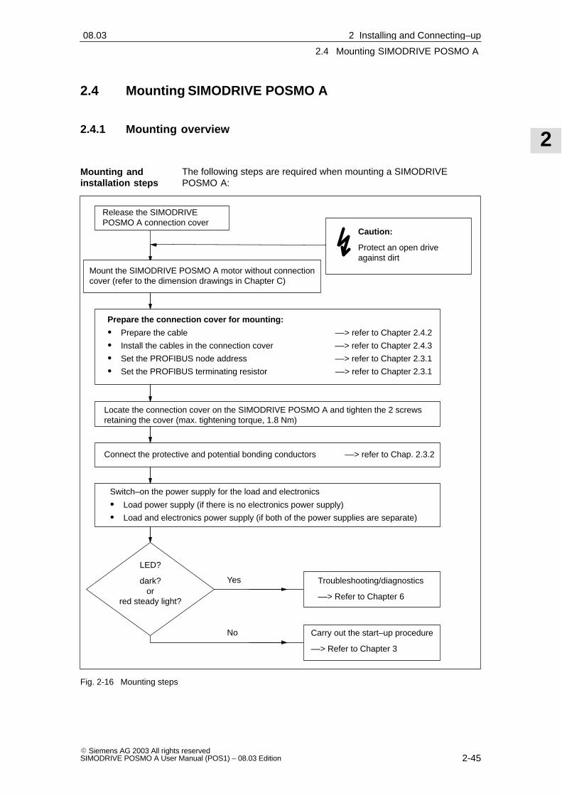
2
2.4 Mounting SIMODRIVE POSMO A
2-45� Siemens AG 2003 All rights reservedSIMODRIVE POSMO A User Manual (POS1) – 08.03 Edition
2.4 Mounting SIMODRIVE POSMO A
2.4.1 Mounting overview
The following steps are required when mounting a SIMODRIVEPOSMO A:
LED?
dark?or
red steady light?
Yes
No
Caution:
Protect an open drive against dirt
Release the SIMODRIVEPOSMO A connection cover
Troubleshooting/diagnostics
––> Refer to Chapter 6
Locate the connection cover on the SIMODRIVE POSMO A and tighten the 2 screwsretaining the cover (max. tightening torque, 1.8 Nm)
Mount the SIMODRIVE POSMO A motor without connectioncover (refer to the dimension drawings in Chapter C)
Switch–on the power supply for the load and electronics
� Load power supply (if there is no electronics power supply)
� Load and electronics power supply (if both of the power supplies are separate)
Carry out the start–up procedure
––> Refer to Chapter 3
Prepare the connection cover for mounting:
� Prepare the cable ––> refer to Chapter 2.4.2
� Install the cables in the connection cover ––> refer to Chapter 2.4.3
� Set the PROFIBUS node address ––> refer to Chapter 2.3.1
� Set the PROFIBUS terminating resistor ––> refer to Chapter 2.3.1
Connect the protective and potential bonding conductors ––> refer to Chap. 2.3.2
Fig. 2-16 Mounting steps
Mounting andinstallation steps
2 Installing and Connecting–up02.9908.03

2
2.4 Mounting SIMODRIVE POSMO A
2-46� Siemens AG 2003 All rights reserved
SIMODRIVE POSMO A User Manual (POS1) – 08.03 Edition
2.4.2 Preparing the cable
Note
We recommend that connector sleeves are used, but these are notabsolutely necessary.
The outer cable diameter should be maintained in order to guaranteethe IP 54 / IP64 / IP65 degree of protection.
� 2 x max. 4 mm2, with or without shield, flexible conductor (finely–stranded)
� Gland:
PG13.5 (with shield connection) for outer diameter = 6 – 12 mm
10120
10 not to scale
6 – 12Load cable
(shieldis notabsolutelyrequired)
Shield
Fig. 2-17 Preparing the load power supply cable
� 2 x 0.35 mm2, with shield
� Gland:
PG13.5 (with shield connection) for outer diameter = 6 – 12 mm
5100
8 not to scale
6 – 12PROFIBUScable
(withoutelectronicspower supply)
Shield
Fig. 2-18 Preparing the PROFIBUS cable
Recommendation for 2–conductor cables sold by the meter: LXV1830-3EH10
Cable for the loadpower supply
Cable forPROFIBUS (withoutelectronics powersupply)
2 Installing and Connecting–up 02.9908.03

2
2.4 Mounting SIMODRIVE POSMO A
2-47� Siemens AG 2003 All rights reservedSIMODRIVE POSMO A User Manual (POS1) – 08.03 Edition
� 3 x 0.75 mm2, with or without shield––> for the electronics power supply
+2 x 0.35 mm2, with shield ––> for PROFIBUS
not to scale
PROFIBUScable
(withelectronicspower supply)
1) Remove cores which are not used
1)
5100
8
6 – 12
Shield
10120
PROFIBUS
Fig. 2-19 Preparing the PROFIBUS cable with electronics power supply
Recommendation for 5–conductor cables sold by the meter:6ES7194-1LY00-0AA0
� 2 x 3 x max. 0.75 mm2, with shield, flexible conductor (finely–stranded)
� Gland:
The dummy plug provided should be replaced by a suitable PG11gland (e.g.: Pflitsch Company, type PG15152m2x6 – gland assemblyPG11/13.5 mounted using a multi–sealing insert for 2 cables with6 mm diameter).
10120
10not to scale
8 – 12I/O cable
Shield
1) Remove coreswhich are not used
1)
1)
Fig. 2-20 Preparing cables for inputs/outputs
Cable forPROFIBUS (with electronicspower supply)
Cable forInputs/outputs
2 Installing and Connecting–up02.9908.02

2
2.4 Mounting SIMODRIVE POSMO A
2-48� Siemens AG 2003 All rights reserved
SIMODRIVE POSMO A User Manual (POS1) – 08.03 Edition
Cross–section: � 4 mm2
Thread: M5 x 10, hole
Note:
� The potential bonding conductor should berouted as far as possible, in parallel to theProfibus cable. This increases thePROFIBUS noise immunity.
� It is not permissible that protectiveconductors are interrupted (refer to Chapter2.3.2)
Torx T20
max. 3 Nm
Fig. 2-21 Potential bonding conductor and protective conductor
The following pre–assembled cable is shown in Fig. 2-22:
� The PROFIBUS cable with electronics power supply
Fig. 2-22 Example: Pre–assembled cable for PROFIBUS
Cables forpotential bondingand protectiveconductor
Example:Cables preparedfor installation
2 Installing and Connecting–up 02.9908.03
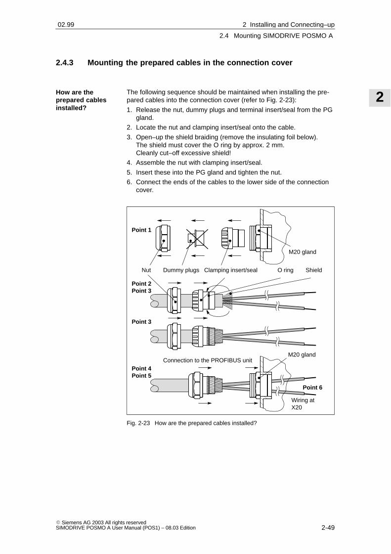
2
2.4 Mounting SIMODRIVE POSMO A
2-49� Siemens AG 2003 All rights reservedSIMODRIVE POSMO A User Manual (POS1) – 08.03 Edition
2.4.3 Mounting the prepared cables in the connection cover
The following sequence should be maintained when installing the pre-pared cables into the connection cover (refer to Fig. 2-23):
1. Release the nut, dummy plugs and terminal insert/seal from the PGgland.
2. Locate the nut and clamping insert/seal onto the cable.
3. Open–up the shield braiding (remove the insulating foil below).The shield must cover the O ring by approx. 2 mm.Cleanly cut–off excessive shield!
4. Assemble the nut with clamping insert/seal.
5. Insert these into the PG gland and tighten the nut.
6. Connect the ends of the cables to the lower side of the connectioncover.
Clamping insert/sealNut
Ó
Ó
Shield
Connection to the PROFIBUS unit
O ring
M20 gland
Ó
Ó
ÓÓÓÓÓÓÓÓ
M20 gland
Ó
Ó
Dummy plugs
Point 1
Point 3
Point 4Point 5
Point 2Point 3
Wiring atX20
Point 6
Fig. 2-23 How are the prepared cables installed?
How are theprepared cablesinstalled?
2 Installing and Connecting–up02.99

2
2.4 Mounting SIMODRIVE POSMO A
2-50� Siemens AG 2003 All rights reserved
SIMODRIVE POSMO A User Manual (POS1) – 08.03 Edition
Fig. 2-24 Example: PG gland with all of the individual parts and components
The following diagrams show a connection cover that has been con-nected–up:
� Connection cover from the top ––> refer to Fig.8 2-25
� Connection cover from the bottom ––> refer to Fig. 2-26
Fig. 2-25 Connection cover with the cables inserted: View from the top
Example:Connection covermounted
2 Installing and Connecting–up 02.9908.03
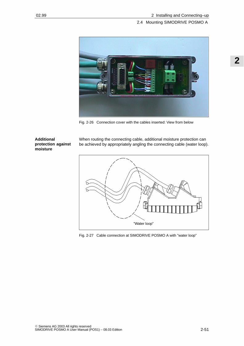
2
2.4 Mounting SIMODRIVE POSMO A
2-51� Siemens AG 2003 All rights reservedSIMODRIVE POSMO A User Manual (POS1) – 08.03 Edition
Fig. 2-26 Connection cover with the cables inserted: View from below
When routing the connecting cable, additional moisture protection canbe achieved by appropriately angling the connecting cable (water loop).
”Water loop”
Fig. 2-27 Cable connection at SIMODRIVE POSMO A with ”water loop”
Additionalprotection againstmoisture
2 Installing and Connecting–up02.99

2
2.5 Gearbox selection
2-52� Siemens AG 2003 All rights reserved
SIMODRIVE POSMO A User Manual (POS1) – 08.03 Edition
2.5 Gearbox selection
2.5.1 Gearboxes for SIMODRIVE POSMO A –75 W
For SIMODRIVE POSMO A – 75 W, the following gearboxes can beselected and used according to Table 2-4:
Table 2-4 System data, modular gearbox with planetary/worm gearboxes
Gearboxtype
Stagenum-
Step-down
Effi-ciency
Torque Ratedspeedtype num-
berdownratio
ciencyPermissible1) Available
speedber ratio
S1 shortterm
S1 S325 %1 min
n(S1)
iGearbox �Gearbox [Nm] [Nm] [Nm] [Nm] [RPM]
Without
gearbox– – – – – 0.18 0.36 3300
14.5 0.85 1.2 2.4 0.7 1.4 733
18 0.85 1.2 2.4 1.2 2.4 413
Planetary20.25 0.72 8 16 2.6 5.2 163
Planetarygearbox
2 36 0.72 8 16 4.7 9.3 92gearbox
2
50 0.72 8 16 6.5 13.0 66
3126.5625 0.61 24 48 13.9 27.8 26
3162 0.61 24 48 17.8 35.6 20
Worm5 0.70 2 4 0.6 1.3 660
Wormgear2)3) 1 24 0.50 3.5 7 2.2 4.3 138gear2)3) 1
75 0.25 4 8 3.4 6.8 44
1) The specified permissible gearbox torque may not be exceeded.Gearboxes can be briefly loaded (1 – 2 s when starting) with higher torques up to a maximum of twice thecontinuous torque without causing permanent damage (but this does have a negative impact on thegearbox lifetime). The gearbox could be destroyed if this limit is exceeded.The current limits of the positioning motor are preset in the factory so that gearboxes cannot be destroyeddue to being over–stressed.
2) Notice: If the worm gear has to be rotated due to the mechanical design, then the mounting screws mustbe subsequently tightened to a torque of 2 Nm and secured using Loctite 274. No warranty is acceptedfor damage caused by incorrect changes.
3) Torsional play < 1°
Reader’s note
Additional gearbox data ––> refer to Chapter 2.6.1
Dimension drawings of motorsand gearboxes ––> refer to Chapter C.1
Gearbox-dependent parameters ––> refer to Chapter 5.6.3
Modular gearbox,75 W motor
2 Installing and Connecting–up 02.9905.03

2
2.5 Gearbox selection
2-53� Siemens AG 2003 All rights reservedSIMODRIVE POSMO A User Manual (POS1) – 08.03 Edition
2.5.2 Gearboxes for SIMODRIVE POSMO A – 300 W
For SIMODRIVE POSMO A – 300 W, the following gearboxes can beselected and used according to Table 2-5:
Table 2-5 System data, modular gearbox with planetary gears
Gearboxtype
Stagenum-
Step-down
Effi-ciency
Torque Ratedspeedtype num-
berdownratio
ciencyPermissi-
ble1)Available
speed
S1 S325 %4 min
S36.25 %4 min
n(S1)
iGearbox �Gearbox [Nm] [Nm] [Nm] [Nm] [RPM]
Without
gearbox
– – – – 0.48 0.95 1.9 3500
14 0.90 26 1.7 3.4 6.8 875
17 0.90 26 3.0 6.0 12.0 500
Planetary12 0.85 36 4.9 9.7 19.4 292
Planetarygear 2
20 0.85 42 8.2 16.2 32.3 175gear 2
35 0.85 44 14.3 28.3 44.0 100
49 0.85 44 20.0 39.6 44.0 71
3 120 0.80 100 46.1 91.2 100.0 29
1) The specified permissible gearbox torque may not be exceeded.The gearbox could be destroyed if this limit is exceeded.The current limits of the positioning motor are preset in the factory so that gearboxes cannot be destroyeddue to being over–stressed.
Reader’s note
Additional gearbox data ––> refer to Chapter 2.6.2
Dimension drawings of motors and gearboxes ––> refer to Chapter C.2
Gearbox-dependent parameters ––> refer to Chapter 5.6.3
Mounting or replacing gearboxes ––> refer to Chapter 7.2
Modular gearbox,300 W motor
2 Installing and Connecting–up02.9905.03

2
2.6 Technical data
2-54� Siemens AG 2003 All rights reserved
SIMODRIVE POSMO A User Manual (POS1) – 08.03 Edition
2.6 Technical data
2.6.1 Technical data for SIMODRIVE POSMO A – 75 W
Table 2-6 Technical data for the POSMO A – 75 W positioning motor
Designation Description
Electricaldata
Load power supply Supply voltage: 24 V DC � 20 %
Current drain: rated: � 4.5 A
for 200% overload (S3): � 9 A
Note:
The rated output and rated speed are reduced when the 24 Vpower supply voltage is fallen below.Electrical
data Electr. power supply
(optional)
Voltage: 24 V DC � 20 %
Current drain: �250 mA
Digital inputs Voltage: 24 V DC � 20 %
Current drain: �15 mA
Digital outputs Maximum current/output: 100 mA
Motor speed/torquecharacteristic
M/ncharacteristic
Motor withoutgearbox
UIN = 24 V DC
n[rev/min]
2000nN = 3300
nno–load = 3600
4.5
9
I [A] M [Nm]
0.18
0.36
200% overload(75 W)
Ratedoperatingpoint(62.5 W)
No–loadoperatingpoint
0
S3 intermittent duty
S1 continuousduty
0 ... 45 °Cup to 65 °C with continuous motor current reduction
Permissibleambient tem-perature
IS1 [A]
ϑ [°C]45
4.5
0 6550
3
2
1
4
55 60
Continuous motor currentreduced as a function of theambient temperature
2 Installing and Connecting–up 02.99

2
2.6 Technical data
2-55� Siemens AG 2003 All rights reservedSIMODRIVE POSMO A User Manual (POS1) – 08.03 Edition
Table 2-6 Technical data for the POSMO A – 75 W positioning motor, continued
Designation Description
Degree ofprotection
EN 10034Part 5
IEC 34-5
IP 54Note:IP40 at the motor shaft and planetary gearbox shaft. If necessary, an external seal mustbe provided. The shaft may not run in an oil bath. If necessary, grease lubrication mustbe provided.
Installationaltitude
and
permissibleoutput
Installation altitude above sea level in m Output as a % of the rated output1000 1001500 972000 942500 903000 863500 824000 77
Motor type Permanent–magnet brushless servomotor
(brushless DC: BLDC)
Cooling Non–ventilated (free convection)
Note:The clearance �100 mm must be maintained on at least threesides of the SIMODRIVE POSMO A to adjacent parts andcomponents
Overload monitoring i2t limiting
Measuring system
(integrated)
Incremental
Resolution: 816 increments/motor revolution
Motor data
Rated motor speed 3,300 RPM (S1)2,000 RPM (S3, 25 %, 1 min)
Note:The data is only va-lid for supply volta-
Motor dataRated motor torque(without gearbox)
0.18 Nm (S1)0.36 Nm (S3, 25 %, 1 min)
The data is only va-lid for supply volta-ges of � 24 V
Rated motor power(without gearbox)
62.5 W (S1)75 W (S3, 25 %, 1 min)
Rated motor current 4.5 A
Motor efficiency 65 %
Motor moment of iner-tia
600 gcm2
Shaft load capability(motor shaft)
Axial load max. 150 NRadial load max. 150 N(effective 20 mm above the plane where the motor is bolted)
S1 - continuous duty The motor can operate continually at rated load without thepermissible temperature being exceeded.Duty cycle = �
Operatingpossibilities(excerpt fromVDE 0530)
S3 Intermittent duty
S3 –25 %
The motor can only be operated at rated load during thepower–on duration specified as a percentage of the load dutycycle without the permissible temperature being exceeded.The equipment is powered down in the no–load interval.Overload factor = 2Duty cycle = 1 minDuration = 25 % of the duty cycle
2 Installing and Connecting–up02.99

2
2.6 Technical data
2-56� Siemens AG 2003 All rights reserved
SIMODRIVE POSMO A User Manual (POS1) – 08.03 Edition
Table 2-6 Technical data for the POSMO A – 75 W positioning motor, continued
Designation Description
Measuringsurfacesound–pres-sure levelEN 21680Part 1
max. 55 dB (A) Motor without gearboxNote:Speed range: 0 –3300 RPM
Backlash 1-stage planetary gearbox: 1.0 degrees
2-stage planetary gearbox: 1.0 degrees
3-stage planetary gearbox: 1.5 degrees
Worm gear: <1.0 degrees
Shaft load capability
(gearbox shaft)
Axial load Radial load(at center of key)
Planetary gear max. 500 N max. 350 N
Worm gear max. 300 N max. 500 N
Gearboxdata
Gearbox lifetime A generally valid statement cannot be made about the lifetimeas a result of the various possible applications and the resul-ting load types as well as varying ambient conditions.
Factors which influence the lifetime include:
� Duty types from continuous operation with one direction ofrotation up to extreme starting/stopping operation with loadlevels from partial load up to full load and significant surgeloading.
� External mechanical loads in the form of vibration andshock.
� The ambient temperature and humidity/moisture
Weights
� Motor without gearbox: 3.1 kg
� Motor with 1-stage gearbox: 3.5 kg
� Motor with 2-stage gearbox: 3.7 kg
� Motor with 3-stage gearbox: 3.9 kg
� Motor with worm gear: 3.5 kg
Climaticambientconditions
Relevant Standards IEC 68-2-1, IEC 68-2-2
Climatic ope-
Operating temperaturerange
0 ... 45 �C
Climatic ope-rating condi-tions
Extended operatingtemperature range
to +65 �C with continuous reduced motor currenttions
Relevant Standards acc. to DIN EN 60721, Part 3-3 Class 3K5
Climatic
Transport and storagetemperature range
–40 ... +70 �C
Climatictransport andstorage
Relevant Standards acc. to DIN EN 60721, Parts 3-1 and 3-2 Classes 2K4 and 1K4transport andstorageconditions
Note:Data applies for components which have been packed readyfor transport.
Mechanicalambientconditions
Relevant Standards IEC 68-2-32
2 Installing and Connecting–up 02.9905.03

2
2.6 Technical data
2-57� Siemens AG 2003 All rights reservedSIMODRIVE POSMO A User Manual (POS1) – 08.03 Edition
Table 2-6 Technical data for the POSMO A – 75 W positioning motor, continued
Designation Description
� Vibration stressing in operation
Frequency range
2 ... 9 Hz
With constant deflection = 7 mm
Tested vibra-tion and
Frequency range
9 ... 200 Hz
With constant acceleration = 20 m/s2 (2 g)
tion andshock stres-sing in opera-
Relevant Standards IEC 68-2-6, DIN EN 60721 Part 3-0 and Part 3-3 Class 3M6shock stres-sing in opera-tion
� Shock stressing in operationtion
Peakacceleration
max. 250 m/s2 (25 g)
Shock duration 6 ms
Relevant Standards DIN EN 60721 Part 3-0 and Part 3-3 Class 3M6
Vibration andRelevant Standards DIN EN 60721 Part 3-3 Class 2M2
Vibration andshock stres-sing duringtransport
Note:
Data applies for components which have been packed readyfor transport.
Pollutantstressing
Relevant Standards IEC 68-2-60
2 Installing and Connecting–up02.9908.01

2
2.6 Technical data
2-58� Siemens AG 2003 All rights reserved
SIMODRIVE POSMO A User Manual (POS1) – 08.03 Edition
2.6.2 Technical data for SIMODRIVE POSMO A – 300 W
Table 2-7 Technical data for the POSMO A – 300 W positioning motor
Designation Description
Electricaldata
Load power supply Supply voltage: 48 V DC � 20 %24 V DC � 20 % (optional)
Current drain: � 5.25 A (for S1)
Note:
� A supply voltage less than 48 V means:
––> lower speed
� For motors with integrated holding brake, the power supplyvoltage must be > 24 V DC.
Electr. power supply
(optional)
Voltage: 24 V DC � 20 %
Current drain: �500 mA
Digital inputs Voltage: 24 V DC � 20 %
Current drain: �15 mA
Digital outputs Maximum current/output: 100 mA
Motor torque/speed cha-racteristic
M/ncharacteristic
Motor withoutgearbox
n [rev/min]2000
Speed limit = 3800
I [A] M [Nm]
Current limit S3
Rated operating point48 V, 300 W
21.0
1000 40003000
0.4
0.8
1.2
1.6
2.0
5.25 Current limit S1 (I2t)
Voltage limitingcharacteristic 24 V
Voltage limitingcharacteristic 48 V
Rated operating point24 V, 100 W
10.5
15.75
0.0 0.0
S3 intermittent duty
S1 continuous duty
Continuous output176 W
0.95
1.9
2 Installing and Connecting–up 02.9904.01

2
2.6 Technical data
2-59� Siemens AG 2003 All rights reservedSIMODRIVE POSMO A User Manual (POS1) – 08.03 Edition
Table 2-7 Technical data for the POSMO A – 300 W positioning motor, continued
Designation Description
S1 - continuous duty The equipment can operate continually at rated load withoutthe permissible temperature being exceeded.
Duty cycle = �
Operatingpossibilities
(excerpt from
S3 - intermittent duty The equipment can only be operated at rated load during thepower–on duration specified as a percentage of the load dutycycle without the permissible temperature being exceeded.The equipment is powered down in the no–load interval.
(excerpt fromVDE 0530)
S3 –25 % Power–on duration = 25 % (� 60 s) ––> at 3000 RPM and 0.95 Nm
Duty cycle = 4 min
S3 – 6.25 % Power–on duration = 6.25 % (� 15 s) ––> at 2000 RPM and 1.9 Nm
Duty cycle = 4 min
Measuringsurfacesound–pres-sure level
EN 21680Part 1
max. 55 dB (A)
max. 70 dB (A)
Motor without gearbox
Motor with 2-stage gearbox
Note:
Speed range: 0 – 3000 RPM
0 ... 45 °Cup to 65 °C with continuous motor current reduction
Permissibleambient tem-perature
IS1 [A]
ϑ [°C]45
5.25
0 6550
3
2
1
4
55 60
Continuous motor currentreduction as a function of theambient temperature
5
Degree ofprotection
EN 10034Part 5
IEC 34-5
IP64 for the motor, electronics
IP54 for the gearbox
IP65 for the motor, electronics and gearbox (optional)
Installationaltitude
and
permissiblepower
Installation altitude above sea level in m Output as a % of the rated output
1000 100
1500 97
2000 94
2500 90
3000 86
3500 82
4000 77
2 Installing and Connecting–up02.9904.0108.02

2
2.6 Technical data
2-60� Siemens AG 2003 All rights reserved
SIMODRIVE POSMO A User Manual (POS1) – 08.03 Edition
Table 2-7 Technical data for the POSMO A – 300 W positioning motor, continued
Designation Description
Motor type 3–phase brushless servomotorNote:The motor corresponds to the 1FK6 motor series.
Cooling Non–ventilated (free convection)Note:The clearance �100 mm must be maintained to adjacentparts and components on at least three sides of the SIMO-DRIVE POSMO A
Overload monitoring i2t limiting
Measuring system(integrated)
IncrementalResolution: 4096 increments/motor revolution
Rated motor speed 3500 RPM (S1)3000 RPM (S3, 25 %, 4 min)
Note:
The data is only va-lid for supply volta-Rated motor torque
(without gearbox)0.48 Nm (S1)0.95 Nm (S3, 25 %, 4 min)
The data is only va-lid for supply volta-ges of � 48 V
Motor data
Rated motor power(without gearbox)
176 W (S1)300 W (S3, 25 %, 4 min)
Motor data Rated motor current 5.25 A (S1)10.5 A (S3, 25 %, 4 min)
Motor efficiency 75 % motor68 % motor and drive unit
Motor moment of iner-tia
Ratio i: without holding brake: with holding brake:without gearbox 58.0 10–6 kgm2 65.0 10–6 kgm2
4 89.0 10–6 kgm2 96.0 10–6 kgm2
7 87.1 10–6 kgm2 94.1 10–6 kgm2
12 90.4 10–6 kgm2 97.4 10–6 kgm2
20 88.7 10–6 kgm2 95.7 10–6 kgm2
35 87.4 10–6 kgm2 94.4 10–6 kgm2
49 87.4 10–6 kgm2 94.4 10–6 kgm2
120 86.7 10–6 kgm2 93.7 10–6 kgm2
Shaft load capability
(motor shaft)
� Axial load– Motor without holding brake max. 210 N– Motor with holding brake forces not permissible
� Radial load max. 240 N(effective 30 mm above the plane where the motor isbolted)
Brake type EBD 0.13BS
Holding torque M4 1.1 Nm
HoldingDC current 0.4 A
Holdingbrake Opening time 30 msbrake
Closing time 10 ms
Number of emergencybraking operations
2000 with a regenerative feedback energy of 13 Ws
2 Installing and Connecting–up 02.9904.0105.03

2
2.6 Technical data
2-61� Siemens AG 2003 All rights reservedSIMODRIVE POSMO A User Manual (POS1) – 08.03 Edition
Table 2-7 Technical data for the POSMO A – 300 W positioning motor, continued
Designation Description
Backlash 1-stage gearbox: <15 ’ (angular minutes)
2-stage gearbox: <20 ’ (angular minutes)
3-stage gearbox: <25 ’ (angular minutes)
Efficiency 1-stage gearbox: 90 %
2-stage gearbox: 85 %
3-stage gearbox: 80 %
Temperature Max. permissible temperature: 90 �C
Speed at the gearboxinput
Rated input speed: 3000 RPMMaximum input speed (drive–in): 6000 RPM
Note:A POSMO A with gearbox can be briefly operated up to themaximum possible speed (depending on the supply voltage)
Gearboxdata
Planetary gear
Shaft load capability
Radial and axial shaftload capability for thegearbox shaft
0
100
200
300
400
500
600
700
800
100 200 300 400 500 600 700 800 900n2 [RPM]
Fr
per
m [
N]
Fa = 0 N
Fa = 500 N
Fa = 1000 N
Fa [N] axial force
Fr perm [N] permissible radial force
n2 [RPM] drive–out speed
Gearbox lifetime A generally valid statement cannot be made about the lifetimeas a result of the various possible applications and the resul-ting load types as well as varying ambient conditions.
Factors which influence the lifetime include:
� Duty types from continuous operation with one direction ofrotation up to extreme start/stop operation with load levelsfrom partial load up to full load and significant surge loa-ding.
� External mechanical loads in the form of a vibration andshock.
� The ambient temperature and humidity/moisture
Weights
� Motor without gearbox: 3.9 kg
� Motor with 1-stage gearbox: 5.1 kg
� Motor with 2-stage gearbox: 5.4 kg
� Motor with 3-stage gearbox: 8.2 kg
2 Installing and Connecting–up02.9904.0105.03

2
2.6 Technical data
2-62� Siemens AG 2003 All rights reserved
SIMODRIVE POSMO A User Manual (POS1) – 08.03 Edition
Table 2-7 Technical data for the POSMO A – 300 W positioning motor, continued
Designation Description
Climaticambientconditions
Relevant Standards IEC 68-2-1, IEC 68-2-2
Climatic
Operating temperaturerange
0 ... 45 �C
Climaticoperatingconditions
Extended operatingtemperature range
to +65 �C with continuous reduced motor currentconditions
Relevant Standards acc. to DIN EN 60721, Part 3-3 Class 3K5
Climatic
Transport and storagetemperature range
–40 ... +70 �C
Climatictransport andstorage
Relevant Standards acc. to DIN EN 60721, Parts 3-1 and 3-2 Classes 2K4 and 1K4transport andstorageconditions
Note:
Data applies for components which have been packed readyfor transport.
Mechanicalambientconditions
Relevant Standards IEC 68-2-32
� Vibration stressing in operation
Frequency range
2 ... 9 Hz
With constant deflection = 7 mm
Frequency range
9 ... 200 Hz
With constant acceleration = 20 m/s2 (2 g)
TestedRelevant Standards IEC 68-2-6, DIN EN 60721 Part 3-0 and Part 3-3 Class 3M6
Testedvibration andshock
� Shock stressing in operationvibration andshockstressing inoperation
Peakacceleration
max. 250 m/s2 (25 g)
operationShock duration 6 ms
Relevant Standards DIN EN 60721 Part 3-0 and Part 3-3 Class 3M6
Note:
In order to ensure a long lifetime, the motor should be supported if it is subject to exter-nal vibration stressing (e.g. continuous operation at the resonant frequency)
Tapped holes are provided to support the motor.
Vibration andshock
Relevant Standards DIN EN 60721 Part 3-3 Class 2M2shockstressingduringtransport
Note:
Data applies for components which have been packed readyfor transport.
Pollutantstressing
Relevant Standards IEC 68-2-60
�
2 Installing and Connecting–up 02.9904.0108.0108.01

3
3-63� Siemens AG 2003 All rights reservedSIMODRIVE POSMO A User Manual (POS1) – 08.03 Edition
Start–up
3.1 General information on start–up
The following prerequisites must be fulfilled before commissioning thedrive:
1. Has the drive been completely installed, cabled and is it ready to bepowered–up?
––> Refer to Chapter 2
2. Has the PROFIBUS DP node address been set at the connectioncover of SIMODRIVE POSMO A?
––> Refer to Chapter 2.3.1
3. Has the terminating resistor been set at the first and last bus no-des?
––> Refer to Chapter 2.3.1 and Chapter 2.3
4. Is there a master device file (GSD) and has it been installed?
––> Refer to Chapter 4.4.2
SIMODRIVE POSMO A can only be controlled and parameterized viaPROFIBUS. This is the reason that it is absolutely necessary that com-munications are established between the DP master and the ”DP slavePOSMO A” that is to be commissioned.
What are the communication possibilities?
� C1 master SIMODRIVE POSMO A PROFIBUS MASTER
––> Refer to Chapter 3.2.4
� C2 master Parameterizing and Start–up Tool ”SimoCom A”
––> Refer to Chapter 3.2.3
� C1 master SIMATIC S5 or SIMATIC S7
––> Refer to Chapter 4.4
� Third–party master
––> Refer to the documentation associated with the third–party master
Stand–alone operation can be set via P100 and P101:11. This meansthat operation is possible without PROFIBUS communications (refer toChapter 5.5.12).
Prerequisites forstart–up
Communicationsbetween masterand slave
3

3
3.1 General information on start–up
3-64� Siemens AG 2003 All rights reserved
SIMODRIVE POSMO A User Manual (POS1) – 08.03 Edition
Master
PROFIBUS-DPstandard master
Slaves
PROFIBUS DPstandard slave
PROFIBUS DPtelegram data
SIMODRIVE
POSMO A
� S7 - 300 withintegrated DPinterface
� S7 - 400– SFC14 (SW)– SFC15 (SW)
� S7 - 312
� CP 342-5
– FC1 (SW)
– FC2 (SW)
� PC/PG+
– CP 5412
– CP 5511
– CP 5611
� Any third–partymaster
PROFIBUS DP
PROFIBUS-DP
� Install GSD files
� Connect up
� Set the address
� When required, set theterminating resistor
Cyclic data
refer to Chapter 4.2, e.g.
� Control word (STW)
� Status word (ZSW)
Parameterizing data
refer to Chapter 4.3, e.g.
� Parameter number, Index
� Parameter value
For SIMODRIVE POSMO A thefollowing is valid:
� PPO type 1 (PPO1)
Fig. 3-1 Overview of the communications for SIMODRIVE POSMO A
After SIMODRIVE POSMO A has been powered up, the LED has thefollowing status, if no fault/error has been detected:
� LED flashes green
––> bus connection is not established (refer to Chapter 6.1)
Overview of thecommunications
LED afterpower–on
3 Start–up 02.99

3
3.2 Commissioning the DP master
3-65� Siemens AG 2003 All rights reservedSIMODRIVE POSMO A User Manual (POS1) – 08.03 Edition
3.2 Commissioning the DP master
3.2.1 Commissioning and communications for the master
The procedure on how to establish communications between themaster and slave is shown using an example with the followingprerequisites:
Assumptions and prerequisites:
� The master is a SIMATIC S7-315-2 DP.
� The prerequisites for commissioning are fulfilled(refer to Chapter 3.1).
� The ”DP slave POSMO A” should be integrated into an existingSIMATIC S7 project.
� The GSD file for the ”DP slave POSMO A” is available and installed(refer to Chapter 4.4.2).
How communications are established:
1. Open the existing SIMATIC project.
2. In the hardware Catalog under PROFIBUS DP, add the station ”SIMODRIVE POSMO A”.
3. Set the PROFIBUS address under properties.
The same address must be set at the positioning motor (DP slave)using switch S1 (refer to Chapter 2.3.1).
4. Set the I/O address
Part I address O address
PKW 256 – 263 256 – 263 (each 8 bytes, addresses are onlyan example)
PZD 264 – 267 264 – 267 (each 4 bytes, addresses are onlyan example)
5. Close the project and transfer to the master.
6. Power–up the drive and check the LED.
Does the LED have a steady green light?yes ––> Normal operation, communications is error–freeno ––> Evaluate the status of the LED (refer to Chapter 6.1)
The drive itself identifies the selected baud rate.
Note
The DP master can now communicate with the SIMODRIVEPOSMO A DP slave which has been powered–up.
How is acommunicationsestablishedbetween themaster and theslave?
3 Start–up02.99
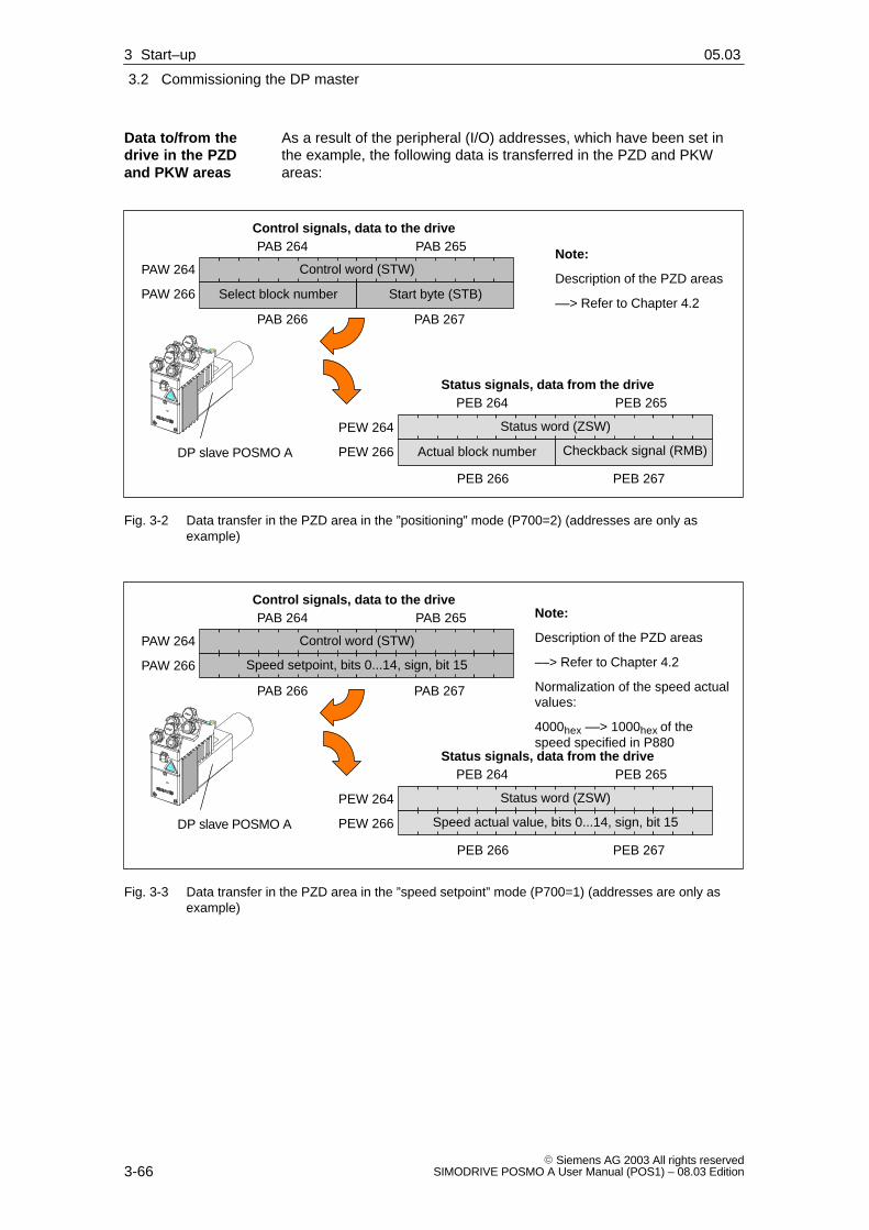
3
3.2 Commissioning the DP master
3-66� Siemens AG 2003 All rights reserved
SIMODRIVE POSMO A User Manual (POS1) – 08.03 Edition
As a result of the peripheral (I/O) addresses, which have been set inthe example, the following data is transferred in the PZD and PKWareas:
Status signals, data from the drive
PEW 264
PEW 266 Actual block number Checkback signal (RMB)
PEB 264 PEB 265
PEB 266 PEB 267
DP slave POSMO A
Note:
Description of the PZD areas
––> Refer to Chapter 4.2
Status word (ZSW)
Control signals, data to the drive
Select block number Start byte (STB)
PAB 264 PAB 265
PAB 266 PAB 267
Control word (STW)PAW 264
PAW 266
Fig. 3-2 Data transfer in the PZD area in the ”positioning” mode (P700=2) (addresses are only asexample)
Status signals, data from the drive
PEW 264
PEW 266
PEB 264 PEB 265
PEB 266 PEB 267
DP slave POSMO A
Note:
Description of the PZD areas
––> Refer to Chapter 4.2
Normalization of the speed actualvalues:
4000hex ––> 1000hex of thespeed specified in P880
Status word (ZSW)
Control signals, data to the drivePAB 264 PAB 265
PAB 266 PAB 267
Control word (STW)PAW 264
PAW 266 Speed setpoint, bits 0...14, sign, bit 15
Speed actual value, bits 0...14, sign, bit 15
Fig. 3-3 Data transfer in the PZD area in the ”speed setpoint” mode (P700=1) (addresses are only asexample)
Data to/from thedrive in the PZDand PKW areas
3 Start–up 02.9905.03

3
3.2 Commissioning the DP master
3-67� Siemens AG 2003 All rights reservedSIMODRIVE POSMO A User Manual (POS1) – 08.03 Edition
Data to the drive
PAW 256
PAW 258
PAW 260
PAW 262
IND (Index) Reserved
PAB 256 PAB 257
PAB 262 PAB 263
Data from the drive
PEW 256
PEW 258
PEW 260
PEW 262
PEB 256 PEB 257
EB 266 EB 267
PWE 1 (parameter value)
PWE 2 (parameter value)
AK PNU (parameter number)– PKE
IND/reserved
PWE
PWE
IND (Index) Reserved
PWE 1 (parameter value)
PWE 2 (parameter value)
AK PNU (parameter number)– PKE
IND/reserved
PWE
PWE
PEB 262 PEB 263
Note:
� The PKW area must beconsistently transferred.
� Description of the PKWarea
––> Refer to Chapter 4.3
DP slavePOSMO A
Fig. 3-4 Data transfer in the PKW area (addresses are only example addresses)
After establishing communications, the commissioning of the DPmaster should be completed.
The following tasks have to be fulfilled:
1. Carry out a function check
You can set the required enable bits here for the function test.
––> Refer to Chapter 4.2
Move the drive as follows:
– Jogging 1 (to the left, 20 % of 3000 RPM motor revolutions)
or
– Jogging 2 (to the right, 20 % of 3000 RPM)
2. Generate the user program for the PZD area
Generating a user program in the DP master to supply the controland status words.
––> Refer to Chapter 4.2
3. Generate the user program for the PKW area
Generate the user software the communicate the PKW area.
––> Refer to Chapter 4.3
Commissioningtasks aftercommunicationshave beenestablished
3 Start–up02.99
3
3.2 Commissioning the DP master
3-68� Siemens AG 2003 All rights reserved
SIMODRIVE POSMO A User Manual (POS1) – 08.03 Edition
3.2.2 SIMATIC S7 function blocks
Using these function blocks, it is simpler to control and parameterize aSIMODRIVE POSMO A positioning motor from a SIMATIC S7 program.
This means that a drive, for example, can be parameterized withoutbeing knowledgeable about PROFIBUS parameter formats and thetask IDs.
The following function blocks are available:
� FB 10 CONTROL_POSMO_A (from 02.00)
� FB 11 PARAMETERIZE_POSMO_A (from 02.00)
� FB 12 PARAMETERIZE_ALL_POSMO_A (from 05.00)
You can obtain all of the function blocks up to Version 1.5 at no chargefrom your local Siemens office (sales partner). However, these functionblocks do not support the ”speed setpoint” mode and will not be furtherinnovated.
The function block with extended functionality (incl. the ”speed setpoint”mode) are available in the ”Drive ES SIMATIC” software package fromVersion 5.3.
Siemens AG accepts no liability and no warranty that these blockexamples operate error–free.
The software license conditions according to Class C apply.
––> Refer to the description of the function blocks which has also beeninstalled
Prerequisites: SIMATIC S7 Manager from Version 4.02
Run the unzipped file ”setup.exe” and following the instructions.
The function blocks are then availale in the SIMATIC Manager underthe ”Posmo A Library Vx” library.
The associated description of the function blocks is available as pdfdocument under:
Start ––> Simatic ––> S7 Manuals––> Posmo A Library
Reader’s note
In order that you always have an up–to–date description whichmatches the blocks, please refer to the information on the blocksprovided in the PDF document which was also installed.
Brief description
Which blocks areavailable?
Where are thesefunction blocks?
Software Class C
Installation
3 Start–up 02.9904.0105.03

3
3.2 Commissioning the DP master
3-69� Siemens AG 2003 All rights reservedSIMODRIVE POSMO A User Manual (POS1) – 08.03 Edition
3.2.3 Parameterizing and start–up tool ”SimoCom A” (from SW 1.5)
A PG/PC is required to install the tool; it must fulfill the following mini-mum requirements:
� Operating system:
Windows 95, Windows 98 or Windows NT
Windows ME or Windows 2000
Windows XP
� 32 MB RAM memory
� 30 MB memory on the hard disk
The ”SimoCom A” parameterizing and start–up tool is available throughthe Internet as follows:
� German
http://www.ad.siemens.de/mc/html_00/info/download/
� English
http://www.ad.siemens.de/mc/html_76/info/download/
The ”SimoCom A” parameterizing and start–up tool can be used for allSIMODRIVE POSMO A drives from SW 1.5 onwards.
The functional scope of the ”SimoCom A” tool is continually adapted tothe expanded functionality of these drives.
In order to parameterize and handle all of the functions of a drive using”SimoCom A”, the optimum matching ”SimoCom A” must be used. Thisdepends on the drive software release.
Reader’s note
Which version of ”SimoCom A” optimally matches which drive andwhich drive software release?
Refer to ”SimoCom A” as follows:
Help ––> info about ”SimoCom A” ... ––> Versions
Prerequisite
Where can I get”SimoCom A”?
Which version isthe optimum”SimoCom A”version?
3 Start–up02.9908.03

3
3.2 Commissioning the DP master
3-70� Siemens AG 2003 All rights reserved
SIMODRIVE POSMO A User Manual (POS1) – 08.03 Edition
This is how you install the ”SimoCom A” tool on your PG/PC:
Reader’s note
The ”readme.txt” file is provided on the software CD. Please observe the information, tips and tricks provided in this file.
1. Insert the software CD into the appropriate drive of your PG/PC.
2. Run the ”setup.exe” file in directory ”disk1” for the required versionof ”SimoCom A”.–> START –> RUN –> OPEN SETUP.EXE –> OK
3. Follow the instructions which the installation program displays step–by–step.
Result:
– The ”SimoCom A” tool has now been installed in the target direc-tory which you selected.
– The tool can e.g. be started as follows: –> START –> PROGRAM –> SIMOCOMA–> SimoComA –> mouse click
This is how you can un–install the ”SimoCom A” parameterizing andstart–up tool from your PG/PC:
� Using the program/operation of ”SimoCom A”
The ”SimoCom A” tool can be e.g. un–installed as follows:
–> START –> PROGRAMME –> SIMOCOMA –> Uninstall SimoComA –> mouse click
� Using the Control Panel just like any other Windows program
– Select the ”control panel”–> START –> SETTINGS –> CONTROL PANEL
– Double–click on the ”Software” symbol
– Select the ”SimoCom A” program from the selection field
– Press the ”add/remove...” button and then following the instruc-tions
You can go into online operation as follows:
� Online operation via the CP 5511 / CP 5611 directly with the fieldbus
PC/PG <––> CP 5511 / CP 5611 <––> PROFIBUS <––> drives
� Online operation via the MPI interface of SIMATIC S7
PC/PG <––> MPI <––> PROFIBUS <––> drives
Installing”SimoCom A”
Un–installing”SimoCom A”
Online operation,”SimoCom A” withdrive
3 Start–up 02.99

3
3.2 Commissioning the DP master
3-71� Siemens AG 2003 All rights reservedSIMODRIVE POSMO A User Manual (POS1) – 08.03 Edition
The following prerequisites must be fulfilled in order to establish onlineoperation between ”SimoCom A” and a drive via the PROFIBUS DPfieldbus:
1. Communication modules, if ”connect via PROFIBUS”
– CP 5511 (PROFIBUS coupling via PCMCIA card)
Configuration: Type 2 PCMCIA card + adapter with 9-pin SUB-D socket to con-nect to PROFIBUS.
Order No. (MLFB): 6GK1551-1AA00
or
– CP 5611 (PROFIBUS coupling through a short PCI card)
Configuration: Short PCI card with 9-pin SUB-D socket to connect to PROFI-BUS.
Order No. (MLFB): 6GK1561-1AA00
– CP 5613 (PROFIBUS coupling through a short PCI card)
Configuration: Short PCI card with 9-pin SUB-D socket to connect to PROFI-BUS DP.Diagnostic LEDsPROFIBUS controller ASPC2 StepE
Order No. (MLFB): 6GK1561-3AA00
For newer PGs, this communications interface is already included.
2. SIMATIC CPU, if ”connect via MPI interface”
A routing–capable SIMATIC–CPU is required for a coupling via MPIinterface.
3. S7-DOS from V5.0
The software is also installed when installing ”SimoCom A”.
4. Connecting cable
– between CP 5511 or CP 5611 and the PROFIBUS fieldbus
or
– between the MPI interface from the PG and SIMATIC CPU
Note
Going online/offline in cyclic operation via PROFIBUS:
While PROFIBUS is in cyclic operation, ”SimoCom A” with CP xxxxcan be connected or disconnected from the fieldbus using the followingplug–in cable without generating an error.
Order No. (MLFB): 6ES7901-4BD00-0XA0 (plug–in cable)
Prerequisites foronline operation
3 Start–up02.9905.03

3
3.2 Commissioning the DP master
3-72� Siemens AG 2003 All rights reserved
SIMODRIVE POSMO A User Manual (POS1) – 08.03 Edition
For ”SimoCom A”, communications should be set as follows viaPROFIBUS–DP:
� Options – Settings – Communications ––> ”Interface” dialog”
� With ”For ”Go online” connect via” set the following: ––> ”direct connection”, if the coupling is directly established
or––> ”routed via S7”, if the coupling is established through theMPI interface
Online operation can be directly established to the drive directly via thefieldbus using the ”Go online” function.
SIMATIC S7-300 (CPU: S7-315-2-DP)
ÄÄÄÄ
Parameterizingand start–up tool”SimoCom A”PG/PC
MPI
or
CP 5511
or
CP 5611
or
CP 5613
PROFIBUS DP
� At the last node (in this case at the left) ––> switch in the terminating resistor (refer toChapter 2.3.1)
� Set the PROFIBUS node address for the slaves (refer to Chapter 2.3.1)
Firstnode(in this case,the master)
––> Switch–interminatingresistor
or
Setup.exe
Fig. 3-5 Example for online operation via PROFIBUS: ”SimoCom A” <––> 2 drives
Settings for”SimoCom A”
Example:Online operationvia PROFIBUS
3 Start–up 02.9905.03

3
3.2 Commissioning the DP master
3-73� Siemens AG 2003 All rights reservedSIMODRIVE POSMO A User Manual (POS1) – 08.03 Edition
Prerequisites:
The parameterizing and start–up tool ”SimoCom A” is installed on thePG/PC and can be started.
The following basic screen is displayed after the first start:
Fig. 3-6 Basic display of ”SimoCom A”
Note
This is what you really need to know when using ”SimoCom A”:
The program attempts to ”think with you”:
� If you select a command, which is presently not available for aspecific reason (e.g. you are offline and wish to ”move an axis ”),then the program does what you would probably wish it to do: It goes ”online”, and offers you a list of drives and after the requireddrive has been selected, it opens the traversing window. However,if you do not wish to do this, then you can exit and continue asrequired.
� Only the information is provided in the dialog boxes which must beavailable as a result of the selected configuration.
Please observe the information on ”SimoCom A” in Table 3-1.
Entry into”SimoCom A”
3 Start–up02.99

3
3.2 Commissioning the DP master
3-74� Siemens AG 2003 All rights reserved
SIMODRIVE POSMO A User Manual (POS1) – 08.03 Edition
The information provided in the following text provides you with somebasic information and instructions on how to handle the parameterizingand start–up tool ”SimoCom A”.
Table 3-1 Information on ”SimoCom A”
Function Description
Tasksthat can be executedusing ”SimoCom A”
� Check the wiring (go into the Online Help: connection diagrams)
� Establish a connection to the drive to be parameterized
� Change the parameters
– The essential parameters are changed, dialog–prompted
– You can change all of the parameters using the expert list
� Traverse the axis
� Diagnose the drive status
– Obtain an overview of all of the connected drives and their status
– Detect the connected hardware
– Display the terminal status
– Alarms and information on how they can be removed
� Carry out diagnostics
– Parameterize test sockets (DAU1, DAU2). Selected signals in the drivecan be routed to the test sockets for measurement with an oscilloscope.
� Save the results
– Save the parameters in the drive FEPROM
– Save the parameters in a file/open a file
– Print the parameters
� Compare parameter sets
This allows the difference between 2 parameters sets to be identified.
� Initialize the drive
The drive can be initialized using this function. It is then necessary toconfigure a drive.
� Load the factory setting
The status of a drive when originally shipped can be established usingthis function.
� Generate a user parameter list.
The user can include a parameter in this list. This list has the samefunctionality as the expert list.
Language Menu ”Option/Settings/Language”
Browser The browser (the lefthand window) can be set to the following areas via thelower buttons:
� Parameter (Par)
� Operator control (OpCo)
� Diagnostics (Diag)
Close/open the browser: Menu ”Options/settings/browser”
Information on”SimoCom A”
3 Start–up 02.99

3
3.2 Commissioning the DP master
3-75� Siemens AG 2003 All rights reservedSIMODRIVE POSMO A User Manual (POS1) – 08.03 Edition
Table 3-1 Information on ”SimoCom A”, continued
Function Description
Working offline ... this means that you are only working at the computer and you do not have aconnection to a drive. Only the opened files are included in the browser under”Operate”.
Working online ... this means that you are connected with one or several drives and ”SimoComA” also recognizes these drives.
This is the case if ”SimoCom A” has already searched for the interface once.
You go online, if
� Your default is set in the menu ”Options/Settings/Communications” (this isrealized when starting ”SimoComA”)
� You make the selection with the operator action ”Search for online drives”
In the online mode, the opened files and all of the drives available via theinterface are contained in the browser under ”Operate”.
Note:
The parameters displayed via ”SimoCom A” are not cyclically read.
Working in the drive
or
in the file
You can work directly in the drive or only at the PC in the file, but only with onedata set at any one time.
For example, you can be connected with a POSMO A – 300 W (4A) and aPOSMO A – 75 W (6A), so that you have access to the parameter sets in bothof the drives – and at the same time have several files open. All of theseparameter sets are displayed in the browser under ”Operate” and also in themenu ”File”.
If you select ”Drive 4A”, then you will see the current status and parameters ofdrive 4A – but no others. When changing over, for example to the ”My.par” file,then you only see the parameters associated with this file.
Parameters files which have been opened can be re–closed usingthe”File/Close file” menu.
Assign the PC thecontrol priority
... means that the ”DP slave POSMO A” should be controlled from the PC.
How is the control authority transferred to the PC?
� The C1 master must signal OFF 1, OFF 2 or OFF 3
� Transfer the control authority to the PC using the menu ”Operator control/control authority for PC”
Returning the controlauthority
... means that the ”DP slave POSMO A” should be controlled from the C1master.
How is the control authority returned?
� Bring the drive to a standstill
� Withdraw the PC controller enable
Procedure when com-missioning
Recommendation: Set the browser to ”Parameter” and work through thefollowing dialog boxes one after the other ”Configuration – re–configure drive”––> ”Mechanical system” ––> ”Traversing blocks”.
1. Configuration ... here, enter the drive type being used, the gearbox stage and the brakingoption (this only applies to the 300 W motor).
If this data is changed, this causes the parameters, which are dependent on it,to be re–calculated, i.e. changes previously made to the parameters involvedare overwritten.
2. Mechanical system ... here, you can define the mechanical system used(e.g. rotary axis?, external gearbox?).
3 Start–up02.99

3
3.2 Commissioning the DP master
3-76� Siemens AG 2003 All rights reserved
SIMODRIVE POSMO A User Manual (POS1) – 08.03 Edition
Table 3-1 Information on ”SimoCom A”, continued
Function Description
3. Limits ... here, you can define the basic limit values and properties of all of the posi-tion–controlled or speed–controlled traversing blocks. This defines the characte-ristics of the time–velocity profile and, for speed control sets, the characteristicsof the time–speed profile. The maximum current and the maximum overcurrentof the drive can be defined.
4. Digital inputs/out-puts
... both digital inputs/outputs can be parameterized here. The function of aninput/output can be very quickly defined by selecting a text. It is then stillpossible to display the actual status of the input/output in SimoCom A or, toinvert an input/output.
5. Monitoring ... here, you can define several parameter values which are required for correctand safe sequence of a traversing motion. This includes, for example:
� Software limit switch
� Maximum following error
� Precise stop and standstill window
Faults and warnings, which are possible in operation, can also be re–definedhere.
6. Controller ... here, you can define the parameters of the control loop.
7. Traversing blocks(only pos mode)
... here, you can generate the traversing programs by parameterizing theindividual traversing blocks.
8. Referencing(only pos mode)
9. Speed setpoint in-terface (only n–setmode, from version4.0)
... here, you can generate the traversing program in an automated way whichallows a reference approach travel to a BERO with or without direction reversal.
... here, you can define the parameters for the speed setpoint interface.
Traverse the drive After the drive has been configured, you can already move the axis from thePC.
Call: Menu ”Operate/Jog/ ...” or menu ”Operate/MDI/ ...”
3 Start–up 02.9905.03

3
3.2 Commissioning the DP master
3-77� Siemens AG 2003 All rights reservedSIMODRIVE POSMO A User Manual (POS1) – 08.03 Edition
Table 3-1 Information on ”SimoCom A”, continued
Function Description
Expert list You can influence the complete parameter set of a drive using the expert list, i.e.you can individually change each parameter.
In this case, the operator is not additionally supported by dialog boxes.
Parameterization using the expert list should only be used in exceptional cases.
Operating information:
� Call: Menu ”Start–up/Additional parameters/Expert list”
� The standard value and the value limits for the actual parameters aredisplayed via the tooltip.
� Modified values only become effective after pressing the Enter key or ifanother parameter was selected. Values which are not active have a yellowbackground.
� Expert list selected ––> Menu ”List” or the righthand mouse key
The following functions can be executed in this window:
– Display filter: Here, you have the possibility of selecting as to which datashould appear in the expert list: e.g. all data or only the controller data.
– Search: Using F3 (or menu ”List/Search), you can search for specificterminals. For instance, you can search for ”temp” if you wish to knowthe value for the electronics temperature.
– Bit–coded values: With the cursor, go to the line and press F4 (or menu”List/bit value”). You then obtain a plain text display of the individual bitsand can select these at a click of the mouse.
Data transfer Also here, the program attempts to ”think with you”:
If you are presently working on a drive and select File/Download into drive” thenthe program assumes that you wish to download a file, still to be selected, intothis particular drive.
If a file is presently open, then the program assumes that using the samecommand, you wish to download this open data set into a drive still to beselected.
If these assumptions are not applicable, then you can always undo bycanceling.
Integrated help The ”SimoCom A” tool is equipped with an integrated help function which sup-ports you when using the ”SimoCom A” and the ”SIMODRIVE POSMO A” drive.
You can call the help function for ”SimoCom A”:
� Using the menu ”Help/help subjects ...” or
� By pressing the ”Help” button or
� By pressing key ”F1”
3 Start–up02.99

3
3.2 Commissioning the DP master
3-78� Siemens AG 2003 All rights reserved
SIMODRIVE POSMO A User Manual (POS1) – 08.03 Edition
3.2.4 Parameterizing and start–up tool C1 master ”SIMODRIVE POSMOA PROFIBUS MASTER”
The ”SIMODRIVE POSMO A PROFIBUS MASTER” allows data to betransferred between a PC, PG or notebook as Class 1 master (C1master) with SIMODRIVE POSMO A via the PROFIBUS–DP fieldbus.
A connection to PROFIBUS is implemented using the SIMATIC NETDP programming interface.
Reader’s note
Limitations and important information should be taken from the readmefile supply with the system.
A description of the tool is available as online help.
You will find installation instructions on the last installation floppy disk.
The most important functions of the master include:
� Controlling SIMODRIVE POSMO A via control signals
� Displaying status signals (e.g. status word, actual values)
� Programming, selecting and starting traversing blocks
� Reading and writing individual parameters
� Saving and downloading all parameters (including the traversingblocks)
� Establishing the factory presetting, etc.
You can obtain the master at no charge from your local Siemens office(sales partner).
The software is available through the Internet as follows:
� German
http://www.ad.siemens.de/mc/html_00/info/download/
� English
http://www.ad.siemens.de/mc/html_76/info/download/
Brief description
What can the C1master do?
Where can I obtainthe C1 master?
3 Start–up 02.99
3
3.2 Commissioning the DP master
3-79� Siemens AG 2003 All rights reservedSIMODRIVE POSMO A User Manual (POS1) – 08.03 Edition
As a minimum, the following hardware and software environment isrequired in order to operate the C1 master:
� The PG, PC or Notebook must have
– Operating system: Windows 95/98
– 32 MB RAM memory
– 10 MB free memory on the hard disk
� Requirements placed on the communications
– CP 5511 (PROFIBUS coupling via PCMCIA card)
Configuration: Type 2 PCMCIA card + adapter with 9-pin SUB-D socket to con-nected to PROFIBUS.
Order No. (MLFB): 6GK1551-1AA00
– CP 5611 (PROFIBUS connection via a short PCI card)
Configuration: Short PCI card with 9-pin SUB-D socket to connect to PROFI-BUS.
Order No. (MLFB): 6GK1561-1AA00
– CP 5613 (PROFIBUS connection via a short PCI card)
Configuration: Short PCI card with 9-pin SUB-D socket to connect to PROFI-BUS DP.Diagnostic LEDsPROFIBUS controller ASPC2 StepE
Order No. (MLFB): 6GK1561-3AA00
For newer PGs, this communications interface is already included.
� Software requirements
– SIMATIC NET,SOFTNET DP/Windows 98 NT 4.0/5.0 or newer
Order No. (MLFB): 6GK1704-5DW��-3AA0
– TCL/TK interpreter Version 8.0 (is included in the installation software)
This is how you can un–install the C1 master from your PG/PC:
� Select the ”control panel” –> START –> SETTINGS –> CONTROL PANEL
� Double–click on the ”Software” symbol
� Select the program to be uninstalled
� Press the ”add/remove...” button and then follow the instructions
Systemrequirements
Un–installing theC1 master?
3 Start–up02.9905.03

3
3.3 Commissioning an axis
3-80� Siemens AG 2003 All rights reserved
SIMODRIVE POSMO A User Manual (POS1) – 08.03 Edition
3.3 Commissioning an axis
The appropriate parameters must be appropriately set to adapt theaxis.
The most important parameters for general settings are:
� P1 Axis type
� P2 Travel per gearbox revolution
� P3 Gearbox ratio
� P4 Dimension unit
� P8 Maximum speed
� P10 Maximum velocity
� P22 Maximum acceleration
The most important parameters for monitoring functions are:
� P6 Software limit switch, start
� P7 Software limit switch, end
� P12 Maximum following error
� P14 Standstill range
Note
There are neither software switches nor traversing range limits in then–set mode (from SW 2.0).
The drive must always be able to rotate endlessly and therefore to beparameterized as rotary axis. It must be de–referenced.
Parameters forgeneral settings(refer toChapter 5.6.2)
Parameters formonitoring(refer toChapter 5.6.2)
3 Start–up 02.9905.03

3
3.3 Commissioning an axis
3-81� Siemens AG 2003 All rights reservedSIMODRIVE POSMO A User Manual (POS1) – 08.03 Edition
How are the assumed values represented in Fig. 3-7 in the appropriateparameters?
POSMO A ÍÍÍÍÍÍÍÍÍ
Table
Gearbox
1 : 4.5
Spindle
20
Traversing range–1000 1000
Motor
3000 RPM
Fig. 3-7 Example: Parameterizing the linear axis
� P1 = 0 :Axis type, linear axis
� P2 = 20 :Travel per gearbox revolution
� P3 = 4.5 :Gearbox ratio
� P4 = 0 :Dimension units mm
� P6 = –1000 :SW limit switch, start
� P7 = 1000 :SW limit switch, end
� P8 = 3000 :Maximum speed
� P10 = 13333.33 :Maximum velocity:vmax = 3000/min � 1/4.5 � 20 mm = 13333.33 mm/min
When parameterizing a linear axis, the maximum possible traversingrange is automatically defined as +/– 200000 mm / degrees / inch.
This means that,
� the software limit switches are de–activated (P0005=P0006) or
� the software limit switches are active but the drive has not beenreferenced,
so that it can be traversed up to a maximum of +/–200000 mm /degrees / inch.
Example:Linear axis,parameterizing
3 Start–up02.9904.01

3
3.3 Commissioning an axis
3-82� Siemens AG 2003 All rights reserved
SIMODRIVE POSMO A User Manual (POS1) – 08.03 Edition
How are the assumed values represented in Fig. 3-8 in the appropriateparameters?
POSMO A
Gearbox
1 : 4.5
Motor
3000 RPM
Gearbox
1 : 4
Traversing range
0 to 360 degrees(Modulo 360 degrees)
Fig. 3-8 Example: Parameterizing a rotary axis
� P1 = 360 :Axis type, rotary axis, modulo 360 degrees
� P2 = 360 :Travel per gearbox revolution
� P3 = 18 (4.5 � 4) :Gearbox ratio
� P4 = 1 :Dimension units, degrees
� P6 = P7 = 0 :For a rotary axes, deactivate the software limit switch
� P8 = 3000 :Maximum speed
� P10 = 60000 :Maximum velocity:vmax = 3000 RPM � 360 degr./18 = 60000 degr./min
For a rotary axis, the internal position actual value calculation limits themaximum modulo value with which a drive can be parameterized.
The following inter–relationship exists:
F in the following is a conversion factor which depends on the dimen-sion system:
Dimension system inch: F = 25.4
Dimension system mm / degrees: F = 1
� POSMO A 75 W:
– P1 < 2147483647 � P2 / (F � 816 � |P3|)
– P2 > P1 � F � 816 � |P3| / 2147483647
– |P3| < 2147483647 � P2 / (F � 816 � P1)
� POSMO A 300 W:
– P1 < 2147483647 � P2 / (F � 4096 � |P3|)
– P2 > P1 � F � 4096 � |P3| / 2147483647
– |P3| < 2147483647 � P2 / (F � 4096 � P1)
The following is valid SW 1.6:
When changing P1, P2 or P3, a check is automatically made in thedrive as to whether these three parameter values fulfill the appropriateformula. If the modified value lies outside the valid range, then the driverejects it and the old value is kept.
Example:Rotary axis,parameterizing
3 Start–up 02.9904.01

3
3.3 Commissioning an axis
3-83� Siemens AG 2003 All rights reservedSIMODRIVE POSMO A User Manual (POS1) – 08.03 Edition
3.3.1 Control structure positioning (pos mode)
The structure of the current/speed and position controller in the”positioning” mode (pos mode) is shown in the following diagram.
ParameterP8 Maximum speed
P9 Ramp–up time
P10 Maximum velocity
P15 Backlash compensation
P16 Maximum overcurrent
P17 P gain n controller
P18 Integral action time, n controller
P19 Kv-factor (position loop gain)
P20 Current setpoint smoothing
P21 Speed setpoint smoothing
P22 Maximum acceleration
P23 Jerk time constant
P28 Maximum current
P54 P gain, n controller, standstill (if P56.2 = 1, this was standard before SW 1.3)
P57 P gain, holding controller, standstill (if P56.2 = 0, this was standard from SW 1.3)
Note:Additional information on the parameters is provided in the parameter list.
––> Refer to Chapter 5.6.2
P8P9P23
Miact
sact
isetnset
nset
sset
P10P15P22P23
P19P57
P21 P17P54
P18 P20
P16 P28
Closed–loopspeed controlled
Closed–looppositioncontrolled
Program control word(PSW.0)
0
1
u
653
2 1
4
Measuring signals1 Current actual value
2 Speed actual value
3 Speed setpoint
4 Position actual value
5 Current setpoint from the speed controller
6 Current setpoint smoothed
Note:These signals can be output via the analogmeasuring outputs.
––> Refer to Chapter 6.3
– –
–
Current controller
Speed controller
Position controller
Fig. 3-9 Closed–loop structure for the ”positioning” mode for SIMODRIVE POSMO A
Description
3 Start–up02.9905.03
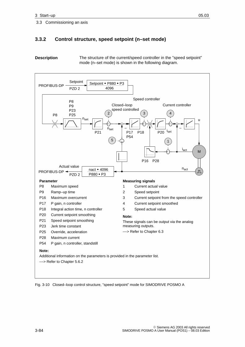
3
3.3 Commissioning an axis
3-84� Siemens AG 2003 All rights reserved
SIMODRIVE POSMO A User Manual (POS1) – 08.03 Edition
3.3.2 Control structure, speed setpoint (n–set mode)
The structure of the current/speed controller in the ”speed setpoint”mode (n–set mode) is shown in the following diagram.
Setpoint � P880 � P3
ParameterP8 Maximum speed
P9 Ramp–up time
P16 Maximum overcurrent
P17 P gain, n controller
P18 Integral action time, n controller
P20 Current setpoint smoothing
P21 Speed setpoint smoothing
P23 Jerk time constant
P25 Override, acceleration
P28 Maximum current
P54 P gain, n controller, standstill
Note:Additional information on the parameters is provided in the parameter list.
––> Refer to Chapter 5.6.2
P8P9P23P25
Miact
nact
isetnset
nset
P21 P17P54
P18 P20
P16 P28
Closed–loopspeed controlled
u
432
1
Measuring signals1 Current actual value
2 Speed setpoint
3 Current setpoint from the speed controller
4 Current setpoint smoothed
5 Speed actual value
Note:These signals can be output via the analogmeasuring outputs.
––> Refer to Chapter 6.3
–
Current controller
Speed controller
4096
P8
Setpoint
PZD 2PROFIBUS-DP
nact � 4096P880 � P3
Actual value
PZD 2PROFIBUS-DP
5
–
Fig. 3-10 Closed–loop control structure, ”speed setpoint” mode for SIMODRIVE POSMO A
Description
3 Start–up 02.9905.03

3
3.3 Commissioning an axis
3-85� Siemens AG 2003 All rights reservedSIMODRIVE POSMO A User Manual (POS1) – 08.03 Edition
3.3.3 Flow diagram to commission a SIMODRIVE POSMO A
Axistype?(P1)
Modulovalue
(P1 = 0)
Enter the modulo value(e.g. P1 = 360 degrees)
Enter a gearbox step–down ratio(P3, e.g. for 1 : 4.5 ––> P3 = 4.5
Traversing distance perrevolution at the gearbox output
(P2)
Determine the maximum velocity(P10 = P8 � P2/P3)
Define the maximum acceleration (P22)The acceleration can be increased up to
the drive current limit
Define the software limit switch (P6, P7)P6 = P7 ––> software limit switch
de–activated
The speed and position controllers arepreset in the factory and these settings
should be adequate for most applications
END
The control loop parameters must beadapted to optimize the system (refer to
Fig. 3-9). Analog measuring outputs can beused to support the optimization procedure
(refer to Chapter 6.3).
yes, required
No
Rotary axis
Linear axis
No
Yes
START
Define the dimension units (P4: 0=mm, 1=degrees, 2=inch)
Optimization?
Modulo?
Set the monitoring functionsP12 (max. following error)
P14 (standstill range)
Prerequisites:
� The start–up tool has beeninstalled
� Communications have beenestablished between the masterand slave
Fig. 3-11 Flow diagram when commissioning the system for the first time in the positioning mode (P700=2)
3 Start–up02.9905.03

3
3.3 Commissioning an axis
3-86� Siemens AG 2003 All rights reserved
SIMODRIVE POSMO A User Manual (POS1) – 08.03 Edition
Enter a gearbox step–down ratio(P3, e.g. for 1 : 4.5 ––> P3 = 4.5
Traversing distance per revolutionat the gearbox output (P2)
Determine the ramp–up time (P9)Determine the override velocity (P24) and
acceleration (P25)
The speed controller is pre–set in thefactory and this setting should be adequate
for most applications
END
The control loop parameters must beadapted to optimize the system (refer to
Fig. 3-10). Analog measuring outputs canbe used to support the optimization
procedure (refer to Chapter 6.3).
yes, required
No
START
Rotary axis (P1 > 0.0)Determine the dimension units (P4: 1 = degrees)
Optimization?
Set the monitoring functionsP1426 (tolerance bandwidth, speed
actual value)P1427 (delay time Nset reached)
Prerequisites:
� Start–up tool has been installed
� Communications establishedbetween the master and slave
Normalization of the maximum speed(P880)
no (P700 = 2)
yes (P700 = 1
n-set mode? Refer to the flow diagram, Fig. 3-11
Fig. 3-12 Flow diagram when commissioning the system for the first time in the speed setpoint mode(P700 = 1)
3 Start–up 02.9905.03

3
3.3 Commissioning an axis
3-87� Siemens AG 2003 All rights reservedSIMODRIVE POSMO A User Manual (POS1) – 08.03 Edition
3.3.4 Optimization runs
The speed and position controller is preset in the factory and should beadequate for most applications.
However, if changes are required, analog measuring outputs can beused to support the optimization procedure (refer to Chapter 6.3).
!Caution
Only appropriately trained personnel with control knowhow mayoptimize the speed and current controllers.
The following parameters should be set in the following sequence inorder to optimize the speed and position controllers:
� P17 P gain, n controller
� P18 Integral action time, n controller
� P20 Current setpoint smoothing
� P19 Kv factor (position loop gain)
� P22 Maximum acceleration
� P21 Speed setpoint smoothing
� P54 P gain, n controller, standstill(if P56.2 = 1, standard before SW 1.3)
� P57 P gain, holding controller, standstill(if P56.2 = 0, standard from SW 1.3)
� P15 Backlash compensation
� P23 Jerk time constant
�
Optimizing thespeed andpositioncontrollers
Parameters foroptimization(refer toChapter 5.6.2)
3 Start–up02.9904.01

3
3.3 Commissioning an axis
3-88� Siemens AG 2003 All rights reserved
SIMODRIVE POSMO A User Manual (POS1) – 08.03 Edition
3 Start–up 02.99
Space for your notes

4
4-89� Siemens AG 2003 All rights reservedSIMODRIVE POSMO A User Manual (POS1) – 08.03 Edition
Communications via PROFIBUS–DP
4.1 General information about PROFIBUS DP
PROFIBUS DP is an international, open fieldbus standard and is definedin the following Standards:
� European fieldbus EN 50170 Part 2
� DIN 19245 Part 1 and 3
� IEC 61158
PROFIBUS DP is optimized for fast, data transfer at the field level fortime–critical applications.
The fieldbus is used for cyclic and non–cyclic data transfer between amaster and the slaves assigned to this master.
For PROFIBUS DP a differentiation is made between master andslave.
� Master (active bus node)
Devices, which represent a master on the bus, define data transferalong the bus, and are therefore known as active bus nodes.
For the masters, a differentiation is made between 2 classes:
– DP master, Class 1 (DPMC1):This designates central master devices which exchange informa-tion with the slaves in a defined telegram cycle.Examples: SIMATIC S5, SIMATIC S7, etc.
– DP master, Class 2 (DPMC2):These are devices to configure, commission, control and visua-lize with the bus operational.Examples: Programming devices, operator control/visualizationdevices
� Slave (passive bus node)
These devices may only receive, acknowledge and transfer messa-ges to a master when so requested.
Reader’s note
The SIMODRIVE POSMO A positioning motor is a slave on thefieldbus. This slave is designated ”DP slave POSMO A” in thefollowing.
Generalinformation
Master and slave
4

4
4.1 General information about PROFIBUS DP
4-90� Siemens AG 2003 All rights reserved
SIMODRIVE POSMO A User Manual (POS1) – 08.03 Edition
At power–up, the ”DP slave POSMO A” automatically detects the baudrate set on the fieldbus.
When commissioning the fieldbus, the baud rate is defined the samefor all devices starting from the master.
Data is transferred between the master and slaves according to themaster/slave principle. The drives are always the slaves.
This permits extremely fast cyclic data transfer.
For SIMODRIVE POSMO A for communications via PROFIBUS, thefollowing properties are involved:
Table 4-1 Essential properties of bus communications
Property Which of these does the ”DP slave POSMOA” have?
Supports 9.6 kbaud Yes
Supports 19.2 kbaud Yes
Supports 45.45 kbaud Yes
Supports 93.75 kbaud Yes
Supports 187.5 kbaud Yes
Supports 500 kbaud Yes
Supports 1.5 Mbaud Yes
Supports 3 Mbaud Yes
Supports 6 Mbaud Yes
Supports 12 Mbaud Yes
Supports the FREEZE control command Yes
Supports the SYNC control command Yes
Supports automatic baud rate search Yes
Station number can be changed via software No
The PROFIBUS node address and the terminating resistor are perma-nently set in the connection cover of SIMODRIVE POSMO A.
––> Refer to Chapter 2.3.1
Data transfertechnology, baudrate
Data transfer viaPROFIBUS
Essentialproperties of buscommunications
Addressing
4 Communications via PROFIBUS DP 02.99

4
4.1 General information about PROFIBUS DP
4-91� Siemens AG 2003 All rights reservedSIMODRIVE POSMO A User Manual (POS1) – 08.03 Edition
PNO Guideline, profile for ”variable–speed drives”
� Cyclic data transfer: PZD part
� Non–cyclic data transfer: PKW part
DP master Class 1
(PLC, e.g. SIMATIC S7)
PROFIBUS-DP
DP slavePOSMO A
Fig. 4-1 Protocol for the ”DP slave POSMO A”
The net data structure for cyclic operation is designated as ParameterProcess Data Object (PPO) in the ”PROFIBUS profile, variable–speeddrives”.
Reference: /P3/ PROFIBUSProfile for variable–speed drives
The net data structure for cyclic data transfer is sub–divided into twoareas, which are transferred in each telegram.
� Process data area (PZD, process data)
This area contains the control words, setpoints and status informa-tion and actual values.
The following data is transferred with the process data:
– control words and setpoints (task: master ––> drive)
or
– status words and actual values (responses: drive––> master)
Description: ––> refer to Chapter 4.2
� Parameter area (PKW, parameter identification value)
This telegram section is used to read and/or write parameters andto read out faults.
Description: ––> refer to Chapter 4.3
Protocols for the”DP slave POSMO A”
Net data structureaccording to PPOs
4 Communications via PROFIBUS DP02.99

4
4.1 General information about PROFIBUS DP
4-92� Siemens AG 2003 All rights reserved
SIMODRIVE POSMO A User Manual (POS1) – 08.03 Edition
The telegrams for cyclic data transfer have the following basic struc-ture:
Net data (PPO)
ParameterIDvalue(PKW)
Processdata(PZD)
Protocol frame
(header)
Protocol frame
(trailer)
Fig. 4-2 Telegram structure for cyclic data transfer
There are 5 defined PPO types (PPO1 to PPO5).
For SIMODRIVE POSMO A, only PPO type 1 (PPO1) can be used.
PPO1 is structured as follows:
� 4 words for the parameter area (PKW area)
� 2 words for the process data area (PZD area)
Table 4-2 Structure of Parameter Process Data Object 1 (PPO 1)
Net data
PKW
� Refer to Chapter 4.3
PZD
� Refer to Chapter 4.2
PKE IND PWEPZD
1PZD
2...
1st word
2nd word
3rd word
4th word
1st word
2nd word
...
PPO1 ...
Abbreviations:
PPO Parameter Process Data Object
PKW Parameter ID value
PKE Parameter ID
IND Sub–index, sub–parameter number, array index
PWE Parameter value
PZD Process data
Telegram structurefor cyclicdata transfer
PPO types
4 Communications via PROFIBUS DP 02.99

4
4.2 Process data (PZD area)
4-93� Siemens AG 2003 All rights reservedSIMODRIVE POSMO A User Manual (POS1) – 08.03 Edition
4.2 Process data (PZD area)
The process data area comprises 2 words for PPO type 1 (PZD1 andPZD 2).
Table 4-3 Structure of the process data (PZD)
Net data
PKW
� Refer to Chapter 4.3
PZD
PKE IND PWEPZD
1PZD
2...
1st word
2nd word
3rd word
4th word
1st word
2nd word
...
PPO1 ...
”Speed setpoint” mode (P700=1)
Bit 15 ... 0 15 ... 8 7 ... 0
Control word(STW)
Start byte(STB)
Master ––> slave
Control signals(refer to Chapter4.2.1)
SelectionBlock number
(AnwSatz)
Status word (ZSW)Checkbacksignal byte
(RMB)
Master <–– slave
Status signals (referto Chapter 4.2.2)
Actual blocknumber
(AktSatz)
”Positioning” mode (P700=2)
Bit 15 ... 0 15 ... 0
Control word(STW)
Master ––> slave
Control signals(refer to Chapter4.2.1)
Speed setpoint, bits 0...14,sign, bit 15
Status word (ZSW)
Master <–– slave
Status signals (referto Chapter 4.2.2)
Speed actual value, bits0...14, sign, bit 15
Abbreviations:
PKW Parameter ID value
PZD Process data
PPO Parameter Process data Object
STW Control word
AnwSatz Select block number
STB Start byte
ZSW Status word
AktSatz Actual block number
RMB Checkback signal byte
Structure
4 Communications via PROFIBUS DP02.9905.03

4
4.2 Process data (PZD area)
4-94� Siemens AG 2003 All rights reserved
SIMODRIVE POSMO A User Manual (POS1) – 08.03 Edition
4.2.1 Description of the control signals (data to drive)
The master issues its commands to the slave using the control word(STW).
Table 4-4 Structure of control word STW for the pos mode
Read–in enable / no read–in enable
Control requested/no control requested
Jogging 1 ON/jogging 1 OFF
Automatic single block operation / automaticExternal block change/no external block change
Start referencing / stop referencing
Jogging 2 ON/jogging 2 OFF
Open holding brake / close holding brake (from SW 1.4)
Bit 15 14 13 12 11 10 9 8 7 6 5 4 3 2 1 0
Reset the fault memoryActivate traversing task (edge)
Enable/intermediate stopOperating condition for positioning/stop
Enable operation/inhibit operationOperating condition/OFF 3
Operating condition/OFF 2ON/OFF 1
Note:
1 signal / 0 signal
Note:
� The signals designated in this way must have at least a ”1” signal in order to be able tooperate a motor.
Furthermore, STW.8 or STW.9 must be set to ”1” for jogging 1 or 2.
Table 4-5 Description of the individual signals in the control word (STW) for the pos mode
Bit Signal name Signal status, signal description
1 ON
Ready
0 ON/OFF 1 0 OFF 1
Shutdown, decelerating along the down ramp, power di-sconnected, tracking operation.
1 Operating condition
Ready
1 Operating condition/OFF 2 0 OFF 2
The power is disconnected and the motor coasts down,power–on inhibit
Control word(STW)(pos mode)
4 Communications via PROFIBUS DP 02.9905.03

4
4.2 Process data (PZD area)
4-95� Siemens AG 2003 All rights reservedSIMODRIVE POSMO A User Manual (POS1) – 08.03 Edition
Table 4-5 Description of the individual signals in the control word (STW) for the pos mode, continued
Bit Signal status, signal descriptionSignal name
1 Operating condition
Ready
2 Operating condition/OFF 3 0 OFF 3
Deceleration along the current limit, power is disconnectedfrom the motor, tracking operation, power–on inhibit
Enable operation /
1 Enable operation
Ready
3 Enable operation / inhibit operation 0 Inhibit operation
Power disconnected from the motor, motor coasts down,”operation inhibited” status
Operating condition for
1 Operating condition for program
The signal must be continuously present in order to executea traversing task.
4Operating condition forprogram/stop
0 Stop
Deceleration along the current limit.
The motor remains stationary with the holding torque.
The actual traversing task is rejected.
1 Operating condition for program
The signal must be continuously present in order to executea traversing task.
5Operating condition forprogram/intermediate stop
0 Intermediate stop
The drive brakes from an active traversing task along theramp to n = 0 and then remains stationary with the holdingtorque.
The traversing task is not rejected.
For a change to bit 5 = 1, the traversing task is continued.
6 Activate travel task (edge)
1/0 Each edge enables a traversing task or a new setpoint(toggle bit).
An edge change may only be realized if bit 12 of the statusword is used to acknowledge that the previous traversing6 Activate travel task (edge)
0/1
An edge change may only be realized if bit 12 of the statusword is used to acknowledge that the previous traversingtask was accepted.
A program start is valid as a traversing task.
7 Reset fault memory
1 Acknowledge faults (0/1 edge)
Refer to Chapter 6.27 Reset fault memory
0 –
8 Jogging 1 ON/jogging 1 OFF
1 Jogging 1 ON
If operation is enabled and positioning is not active ––> thedrive traverses closed–loop speed controlled with joggingsetpoint 1.
––> Refer to Chapter 5.4.1
0 Jogging 1 OFF
4 Communications via PROFIBUS DP02.99

4
4.2 Process data (PZD area)
4-96� Siemens AG 2003 All rights reserved
SIMODRIVE POSMO A User Manual (POS1) – 08.03 Edition
Table 4-5 Description of the individual signals in the control word (STW) for the pos mode, continued
Bit Signal status, signal descriptionSignal name
9 Jogging 2 ON/jogging 2 OFF
1 Jogging 2 ON
If operation is enabled and positioning is not active ––> thedrive traverses closed–loop speed controlled with joggingsetpoint 2.
––> Refer to Chapter 5.4.1
0 Jogging 2 OFF
10 Control from PLC requested1 Not used or permanent 1 signal
10 Control from PLC requested0 –
11 Start referencing /stop referencing
1 Referencing is executed
Prerequisite: Operation enabled11stop referencing
0 Normal operation
12Automatic single blockoperation / automatic
1 Automatic single block operation
Disables programmed path controlled operation.
Each block has to be re–started.12 operation / automatic0 Automatic
Programmed path controlled operation is effective.
13 External block change/no external block change
1 External block change
The active block is interrupted and the subsequent block isselected. This is realized, dependent on the program, withapproximate positioning or precise stop.
When the block change is recognized, the position actualvalue of the axis is written into P55 (signal position).
0 No external block change
14 Read–in enable /no read–in enable
1 Read–in enable
The following program block is enabled for execution.14no read–in enable
0 No read–in enable
15
Open holding brake /brake sequence controleffective
(from SW 1.4)
1 Open holding brake
The integrated holding brake can be controlled using thissignal.
The signal corresponds to P56.4 (open holding brake).
Note:
If the holding brake is controlled using an input terminal withfunction number 26 (open holding brake), then this signalhas no effect.
––> Refer to Chapter 5.5.13
0 Brake sequence control effective
4 Communications via PROFIBUS DP 02.9904.01

4
4.2 Process data (PZD area)
4-97� Siemens AG 2003 All rights reservedSIMODRIVE POSMO A User Manual (POS1) – 08.03 Edition
The master selects the traversing block to be started by entering therequired block number into this control byte.
The selection becomes effective, if:
� If neither a traversing block nor program is active.
� The program or the traversing block has been completely executed.
� The program or the traversing block was canceled by an externalsignal or a fault.
The start byte is compared with a bit mask ”SMStart” (P86:x) program-med in a traversing block.
This means that the program sequence can be influenced via the startbyte.
� P86:x (high byte) = 0: If there is no function
The block is not influenced by the start byte.
� P86:x (high byte) > 0: Function available
The block can only be started if the bits, set in P86:x (high byte), arealso set in the start byte.
The program control can be additionally influenced via P80:x bit 6and bit 7.
Selectblock number(AnwSatz)
Start byte(STB)
4 Communications via PROFIBUS DP02.99

4
4.2 Process data (PZD area)
4-98� Siemens AG 2003 All rights reserved
SIMODRIVE POSMO A User Manual (POS1) – 08.03 Edition
The master issues its commands to the slave using control word STW.
Table 4-6 Structure of the control word (STW) in the n-set mode
Control requested/no control requested
Reserved
Reserved
Open holding brake / close holding brake (from SW 1.4)
Bit 15 14 13 12 11 10 9 8 7 6 5 4 3 2 1 0
Reset the fault memoryEnable setpoint / inhibit setpoint
Ramp–function generator start/ramp–function generator stopRamp–function generator enable
Enable operation/inhibit operationOperating condition/OFF 3
Operating condition/OFF 2ON/OFF 1
Note:
1 signal / 0 signal
Note:
� The signals designated in this way must have at least a ”1” signal in order to be able tooperate a motor.
Table 4-7 Description of the individual signals in the control word (STW) n-set mode
Bit Signal name Signal status, signal description
1 ON
Ready
0 ON/OFF 1 0 OFF 1
Shutdown, decelerating along the down ramp, powerdisconnected, tracking operation.
1 Operating condition
Ready
1 Operating condition/OFF 2 0 OFF 2
The power is disconnected and the motor coasts down,power–on inhibit
1 Operating condition
Ready
2 Operating condition/OFF 3 0 OFF 3
Deceleration along the current limit, power disconnectedfrom the motor, tracking operation, power–on inhibit
Control word(STW)n-set mode?
4 Communications via PROFIBUS DP 02.9905.03

4
4.2 Process data (PZD area)
4-99� Siemens AG 2003 All rights reservedSIMODRIVE POSMO A User Manual (POS1) – 08.03 Edition
Table 4-7 Description of the individual signals in the control word (STW) n-set mode, continued
Bit Signal status, signal descriptionSignal name
Enable operation /
1 Enable operation
Ready
3 Enable operation /inhibit operation 0 Inhibit operation
Power disconnected from the motor, motor coasts down,”operation inhibited” status
Ramp–function generator
1 Enable ramp–function generator
The motor accelerates to the speed setpoint along the para-meterized ramp
4Ramp–function generatorenable 0 � Standstill
The motor does not accelerate up to its speed setpoint
� During motion,motor brakes with the maximum deceleration
5Ramp–function generatorstart/ramp–function
1 Motor accelerates corresponding to the parameterized ramp5 start/ramp–function
generator stop 0 The speed is kept at the actual value
0/1 Setpoint enable (acceleration along the ramp)
6 Enable setpoint /inhibit setpoint
1/0 Setpoint inhibit
� No ramp–up at standstill
� During motion,motor brakes along the ramp
7 Reset fault memory
1 Acknowledge faults (0/1 edge)
Refer to Chapter 6.27 Reset fault memory
0 –
8, 9 Reserved
10 Control from PLC requested1 Not used or permanent 1 signal
10 Control from PLC requested0 –
11
to
14
Reserved
15
Open holding brake /brake sequence controleffective
(from SW 1.4)
1 Open holding brakeThe integrated holding brake can be controlled using thissignal.The signal corresponds to P56.4 (open holding brake).Note:If the holding brake is controlled using an input terminal withfunction number 26 (open holding brake), then this signalhas no effect.––> Refer to Chapter 5.5.13
0 Brake sequence control effective
4 Communications via PROFIBUS DP02.9905.03
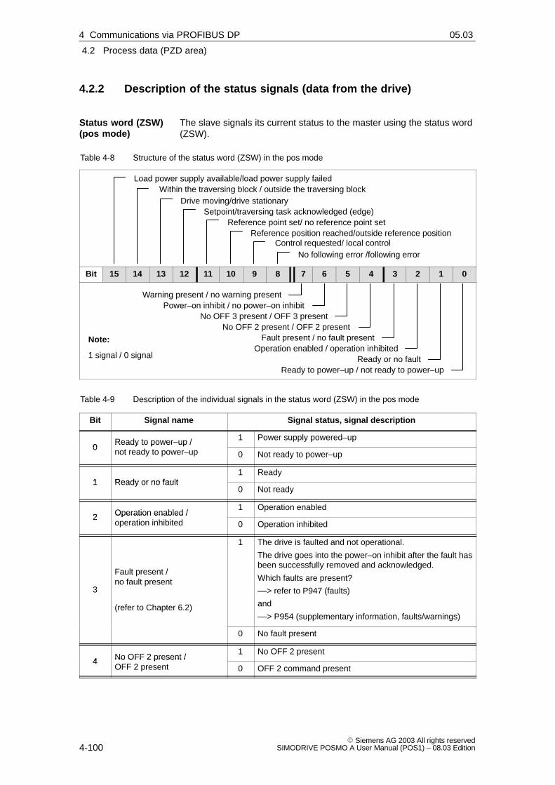
4
4.2 Process data (PZD area)
4-100� Siemens AG 2003 All rights reserved
SIMODRIVE POSMO A User Manual (POS1) – 08.03 Edition
4.2.2 Description of the status signals (data from the drive)
The slave signals its current status to the master using the status word(ZSW).
Table 4-8 Structure of the status word (ZSW) in the pos mode
Load power supply available/load power supply failedWithin the traversing block / outside the traversing block
Reference position reached/outside reference positionControl requested/ local control
No following error /following error
Reference point set/ no reference point setSetpoint/traversing task acknowledged (edge)
Drive moving/drive stationary
Bit 15 14 13 12 11 10 9 8 7 6 5 4 3 2 1 0
Warning present / no warning presentPower–on inhibit / no power–on inhibit
No OFF 3 present / OFF 3 presentNo OFF 2 present / OFF 2 present
Fault present / no fault presentOperation enabled / operation inhibited
Ready or no faultReady to power–up / not ready to power–up
Note:
1 signal / 0 signal
Table 4-9 Description of the individual signals in the status word (ZSW) in the pos mode
Bit Signal name Signal status, signal description
0Ready to power–up /not ready to power–up
1 Power supply powered–up0
Ready to power–up /not ready to power–up 0 Not ready to power–up
1 Ready or no fault1 Ready
1 Ready or no fault0 Not ready
2 Operation enabled / 1 Operation enabled
2 Operation enabled / operation inhibited 0 Operation inhibited
3
Fault present /no fault present
(refer to Chapter 6.2)
1 The drive is faulted and not operational.
The drive goes into the power–on inhibit after the fault hasbeen successfully removed and acknowledged.
Which faults are present?
––> refer to P947 (faults)
and
––> P954 (supplementary information, faults/warnings)
0 No fault present
4 No OFF 2 present /1 No OFF 2 present
4 No OFF 2 present /OFF 2 present 0 OFF 2 command present
Status word (ZSW)(pos mode)
4 Communications via PROFIBUS DP 02.9905.03

4
4.2 Process data (PZD area)
4-101� Siemens AG 2003 All rights reservedSIMODRIVE POSMO A User Manual (POS1) – 08.03 Edition
Table 4-9 Description of the individual signals in the status word (ZSW) in the pos mode, continued
Bit Signal status, signal descriptionSignal name
5No OFF 3 present /OFF 3 present
1 No OFF 3 present5
No OFF 3 present /OFF 3 present 0 OFF 3 command present
6 Power–on inhibit /no power–on inhibit
1 Power–up inhibit
The system can only be powered–up using ”OFF 1”followed by ”ON”.no power–on inhibit
0 No power–on inhibit
7
Warning present /warning not present
(refer to Chapter 6.2)
1 Warning presentThe drive still remains operational. Acknowledgment isnot required.Which warning is present?––> refer to P953 (warnings)and––> P954 (supplementary information, faults/warnings)
0 Warning not present
8 No following error/followingerror
1 No following errorThe dynamic target (reference) actual position compari-son is made within the defined following error window.The following error window is defined using P12(maximum following error) (refer to Chapter 5.6.2).
0 Following error
1 Master, Class 1
9Control requested / local control
(from SW 1.4)
0 No master Class 1 (but master, Class 2)Note:Before SW 1.4 the following applies:The signal is not supported (a permanent ”1” signal).
10 Reference position reached/outside reference position
1 Reference position reachedBefore SW 1.6 the following applies:� The position reference value is located at the end of
a traversing task within the positioning window.� The traversing task is interrupted by a fault, stop or
OFF commands.The following is valid SW 1.6:The behavior is dependent on P56, bit 3:� P56.3=1
– The position reference value is located at the endof a traversing task within the positioning window.
� P56.3=0– The position reference value is located at the end
of a traversing task within the positioning window.– The traversing task was interrupted by a fault,
stop or OFF commands.
0 Outside the reference position
11 Reference point set/1 Referencing was executed and is valid
11 Reference point set/no reference point set 0 Valid reference not available
4 Communications via PROFIBUS DP02.9908.02

4
4.2 Process data (PZD area)
4-102� Siemens AG 2003 All rights reserved
SIMODRIVE POSMO A User Manual (POS1) – 08.03 Edition
Table 4-9 Description of the individual signals in the status word (ZSW) in the pos mode, continued
Bit Signal status, signal descriptionSignal name
12Setpoint / traversing task
1/0 An edge is used to acknowledge that a new traversingtask or setpoint was transferred.
Same signal level as STW.6 (activate traversing task12 traversing task
acknowledged (edge) 0/1 Same signal level as STW.6 (activate traversing task(signal edge)).
13 Drive moving/drive stationary
1 Traversing task is executed (n � 0)
The drive is stationary after it reaches its target position.13 Drive moving/drive stationary
0 Signals the completion of a traversing task or standstill forintermediate stop and stop.
14 Within the traversing block /
1 Within the traversing blockA traversing block is active.
14 Within the traversing block /outside the traversing block 0 Outside the traversing block
No traversing block is active.
Load power supply available/1 Load power supply available
15 Load power supply available/load power supply failed 0 Load power supply failed
This corresponds to the ”undervoltage” fault
Note:When an undervoltage condition is detected, theappropriate fault is signaled and ZSW.15 is set to ”0”.� Before SW 1.3 the following applies:
ZSW.15 is set to ”1”, if, when acknowledging thefault, an undervoltage condition is no longer detected.
� The following is valid from SW 1.3:ZSW.15 is set to ”1” if an undervoltage condition isno longer detected.The fault itself remains until it is acknowledged.ZSW.15 indicates the status of the load power supply,independent of the fault and acknowledgment.
The block number of the actual traversing block is entered into thisstatus byte.
If no block is active, then the block number of the selected traversingblock is signaled back, i.e. the block which should be the next block tobe started.
The programmed block components ”MMStart”, ”MMStop” and”MMPos” corresponding to the program sequence are output in thisstatus byte.
This means that the master has information about programmed blockfor additional processing and evaluation.
Checkback signal (feedback) of the terminal status (from SW 1.4), referto Chapter 5.5.10
� RMB.6 ––> status of terminal 1
� RMB.7 ––> status of terminal 2
Actualblock number(AktSatz)
Checkback signalbyte (RMB)
4 Communications via PROFIBUS DP 02.9904.01

4
4.2 Process data (PZD area)
4-103� Siemens AG 2003 All rights reservedSIMODRIVE POSMO A User Manual (POS1) – 08.03 Edition
The slave signals its current status to the master using the status word(ZSW).
Table 4-10 Structure of the status word (ZSW) for the n–set mode
Load power supply available/load power supply failedReserved
Ramp–up completed / ramp–up activeControl requested/ local control
Speed in the tolerance bandwidth /outside the tolerance bandwidth
Status, terminal 1Status, terminal 2
Drive moving/drive stationary
Bit 15 14 13 12 11 10 9 8 7 6 5 4 3 2 1 0
Warning present / no warning presentPower–on inhibit / no power–on inhibit
No OFF 3 present / OFF 3 presentNo OFF 2 present / OFF 2 present
Fault present / no fault presentOperation enabled / operation inhibited
Ready or no faultReady to power–up / not ready to power–up
Note:
1 signal / 0 signal
Table 4-11 Description of the signals in the status word (ZSW) for the n–set mode
Bit Signal name Signal status, signal description
0Ready to power–up /not ready to power–up
1 Power supply powered–up0
Ready to power–up /not ready to power–up 0 Not ready to power–up
1 Ready or no fault1 Ready
1 Ready or no fault0 Not ready
2 Operation enabled /1 Operation enabled
2 Operation enabled /operation inhibited 0 Operation inhibited
3
Fault present /no fault present
(refer to Chapter 6.2)
1 The drive is faulted and not operational.
The drive goes into the power–on inhibit after the fault hasbeen successfully removed and acknowledged.
Which faults are present?
––> refer to P947 (faults)
and
––> P954 (supplementary information, faults/warnings)
0 No fault present
4 No OFF 2 present /1 No OFF 2 present
4 No OFF 2 present /OFF 2 present 0 OFF 2 command present
Status word (ZSW)(n-set mode)
4 Communications via PROFIBUS DP02.9905.03

4
4.2 Process data (PZD area)
4-104� Siemens AG 2003 All rights reserved
SIMODRIVE POSMO A User Manual (POS1) – 08.03 Edition
Table 4-11 Description of the signals in the status word (ZSW) for the n–set mode, continued
Bit Signal status, signal descriptionSignal name
5No OFF 3 present /OFF 3 present
1 No OFF 3 present5
No OFF 3 present /OFF 3 present 0 OFF 3 command present
6 Power–on inhibit /no power–on inhibit
1 Power–up inhibit
The system can only be powered–up using ”OFF 1”followed by ”ON”.no power–on inhibit
0 No power–on inhibit
7
Warning present /warning not present
(refer to Chapter 6.2)
1 Warning presentThe drive still remains operational. Acknowledgment isnot required.Which warning is present?––> refer to P953 (warnings)and––> P954 (supplementary information, faults/warnings)
0 Warning not present
8Speed in the tolerance band-width / outside the tolerance
1 Speed is within the parameterized tolerance window8 width / outside the tolerance
bandwidth 0 Speed is outside the parameterized tolerance window
1 Master, Class 1
9Control requested/local control
(from SW 1.4)
0 No master Class 1 (but master, Class 2)Note:Before SW 1.4 the following applies:The signal is not supported (a permanent ”1” signal).
10 Ramp–up completed / ramp–1 Ramp–up completed
10 Ramp–up completed / ramp–up active 0 Ramp–up not completed
11 Status, terminal 1 Checkback signal from the parameterized terminal signals
12 Status, terminal 2 Checkback signal from the parameterized terminal signals
13 Drive moving/drive stationary
1 Traversing task is executed (n � 0)
The drive is stationary after it reaches its target position.13 Drive moving/drive stationary
0 Signals the completion of a traversing task or standstill forintermediate stop and stop.
14 Reserved
4 Communications via PROFIBUS DP 02.9905.03

4
4.2 Process data (PZD area)
4-105� Siemens AG 2003 All rights reservedSIMODRIVE POSMO A User Manual (POS1) – 08.03 Edition
Table 4-11 Description of the signals in the status word (ZSW) for the n–set mode, continued
Bit Signal status, signal descriptionSignal name
Load power supply available/1 Load power supply available
15 Load power supply available/load power supply failed 0 Load power supply failed
This corresponds to the ”undervoltage” fault
Note:When an undervoltage condition is detected, the appro-priate fault is signaled and ZSW.15 is set to ”0”.� Before SW 1.3 the following applies:
ZSW.15 is set to ”1”, if, when acknowledging the fault,an undervoltage condition is no longer detected.
� The following is valid SW 1.3:ZSW.15 is set to ”1” if an undervoltage condition is nolonger detected.The fault itself remains until it is acknowledged.ZSW.15 indicates the status of the load power supply,independent of the fault and acknowledgment.
4 Communications via PROFIBUS DP02.9905.03

4
4.2 Process data (PZD area)
4-106� Siemens AG 2003 All rights reserved
SIMODRIVE POSMO A User Manual (POS1) – 08.03 Edition
4.2.3 Example: Operating the drive via the control signals with jogging 1
The drive should be operated with jogging 1.
Assumptions for the slave:
� The drive has been completely commissioned, is connected toPROFIBUS DP has been connected and is ready.
� PROFIBUS node address = 12
Assumptions for the master:
� The DP master is a SIMATIC S7 (CPU: S7-315-2-DP)
� Hardware configuration
– PROFIBUS node address = 12
– Part I address O addressPKW 256 – 263 256 – 263 (not drawn in the example)PZD 264 – 267 264 – 267
DP slavePOSMO A
PROFIBUS-DP
SIMATIC S7-300 (CPU: S7-315-2-DP)
MPI
Output signals atthe DP slave
Input signals atthe DP slave
Control signals
STWAnwSatz/STB
PAW 264 = 0100 0101 0011 1111
Status signals
ZSWAktSatz/RMB
STW, ZSW Control word, Status word
AnwSatz, AktSatz Select block, Actual block
STB, RMB Start byte, Checkback signal byte
PG/PC
PAB 266 = 0 PAB 267 = 0
PEW 264 = 1111 x011 0011 0111PEB 266 = 0 PEB 267 = 0
PAB, PAW Peripheral output byte, word
PEB, PEW Peripheral input byte, word
Fig. 4-3 Example: Operating the drive with jogging 1
Example:Operating thedrivewith jogging 1
4 Communications via PROFIBUS DP 02.9902.00
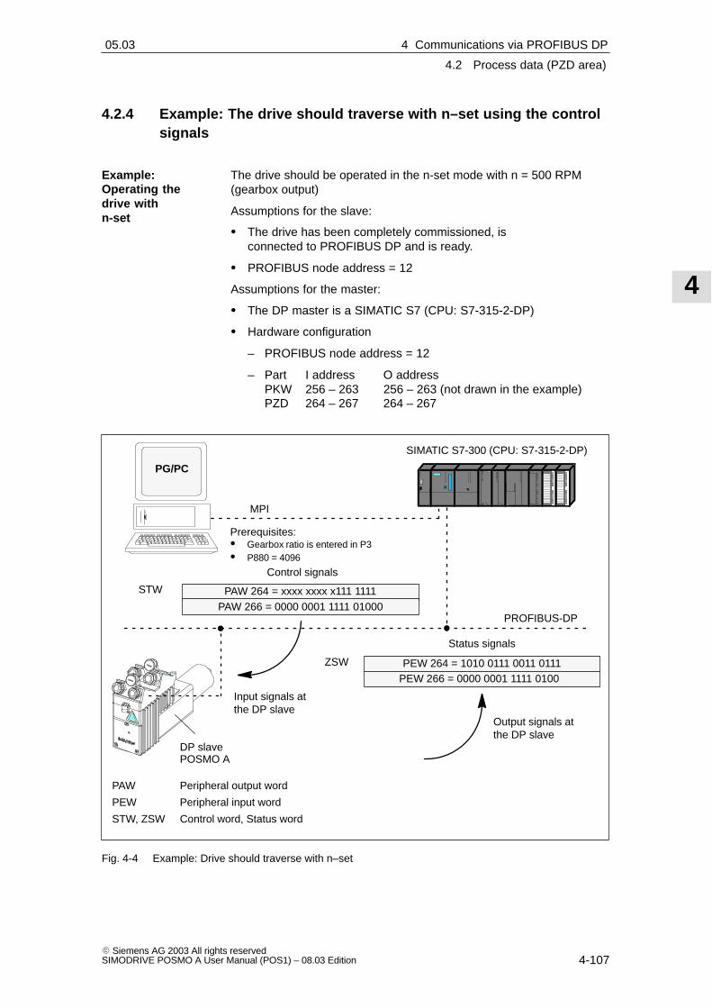
4
4.2 Process data (PZD area)
4-107� Siemens AG 2003 All rights reservedSIMODRIVE POSMO A User Manual (POS1) – 08.03 Edition
4.2.4 Example: The drive should traverse with n–set using the controlsignals
The drive should be operated in the n-set mode with n = 500 RPM(gearbox output)
Assumptions for the slave:
� The drive has been completely commissioned, is connected to PROFIBUS DP and is ready.
� PROFIBUS node address = 12
Assumptions for the master:
� The DP master is a SIMATIC S7 (CPU: S7-315-2-DP)
� Hardware configuration
– PROFIBUS node address = 12
– Part I address O addressPKW 256 – 263 256 – 263 (not drawn in the example)PZD 264 – 267 264 – 267
Prerequisites:� Gearbox ratio is entered in P3� P880 = 4096
DP slavePOSMO A
PROFIBUS-DP
SIMATIC S7-300 (CPU: S7-315-2-DP)
MPI
Output signals atthe DP slave
Input signals atthe DP slave
Control signals
STW PAW 264 = xxxx xxxx x111 1111
Status signals
ZSW
PG/PC
PEW 264 = 1010 0111 0011 0111PEW 266 = 0000 0001 1111 0100
PAW Peripheral output word
PEW Peripheral input word
STW, ZSW Control word, Status word
PAW 266 = 0000 0001 1111 01000
Fig. 4-4 Example: Drive should traverse with n–set
Example:Operating thedrive withn-set
4 Communications via PROFIBUS DP02.9905.03

4
4.2 Process data (PZD area)
4-108� Siemens AG 2003 All rights reserved
SIMODRIVE POSMO A User Manual (POS1) – 08.03 Edition
4.2.5 ”Variable–speed drives” flow diagram
Fault
ZSW =xxxx xxxx xxxx 1xxx
Fault(from any
device status)
Fault resolved,acknowledge faults
i.e. STW.7 =
OFF 3 active
ZSW =xxxx xxxx x10x x000
No OFF 3i.e. STW.2 = 1
OFF 3i.e. STW.2 = 0
(from anydevice status)
OFF 2 active
ZSW =xxxx xxxx x1x0 x000
OFF 2i.e. STW.1 = 0
(from eachdevice status)
Power–on inhibit
ZSWx00x x111 x111 0000
OFF 1i.e.
STW.0 =Not ready topower–up
ZSW =x00x x111 x000 x000
Traversing taski.e.
STW.6 =
Initializingi.e.
STW = 0100 0100 00111111Referencing
OFFi.e.
STW.11 = 0
Referencing
ZSW = 100x 1111 0011 0111
Referencing ONi.e. STW.11 = 1
Operation enabled
ZSW =100x x111 0011 0111
Jogging
ZSW =111x x011 0011 0111
JoggingOFFi.e.
STW.8/9 = 0
Jogging ONi.e. STW.8/9 = 1
VoltageON
NoIntermediate stop
i.e.STW.5 = 1
Intermediate stopi.e.
STW.5 = 0
Intermediate stop
ZSW =110s xp11 0011 0111
Stopi.e.
STW.4 =
Traversing taskactiveZSW =
11ps xp11 0011 0111
STW Control word
ZSW Status word
p Bit dep. on the program (0 or 1)
s Traversing task bit of the STW
x Bit not defined (0 or 1)
Change from 0 to 1 or 1 to 0
Change from 0 to 1 and back again
Change from 1 to 0 and back again
START
No OFF 2i.e. STW.1 = 1
Fig. 4-5 Flow diagram, ”Variable–speed drives” for the pos mode
pos mode
4 Communications via PROFIBUS DP 02.9905.03

4
4.2 Process data (PZD area)
4-109� Siemens AG 2003 All rights reservedSIMODRIVE POSMO A User Manual (POS1) – 08.03 Edition
STW.6 = 11)
STW.6 = 01)
Setpointinhibit
i.e. STW.6 = 0
Enablesetpoint,
i.e. STW.6 = 1
Fault
ZSW =xxxx xxxx xxxx 1xxx
Fault(from any
device status)
Fault resolved,acknowledge faults
i.e. STW.7 =
OFF 3 active
ZSW =xxxx xxxx x10x x000
No OFF 3i.e. STW.2 = 1
OFF 3i.e. STW.2 = 0
(from anydevice status)
OFF 2 active
ZSW =xxxx xxxx x1x0 x000
OFF 2i.e. STW.1 = 0
(from eachdevice status)
Power–on inhibit
ZSWx00x x111 x111 0000
Speed setpoint is acceptedi.e. STW.4/5/6 = 1 (any
sequence)
Initializingi.e.
STW = xxxx xxxx x000 1111
Operation enabled
ZSW =1x0x xxxx x000 1111
Braking down to zerospeed along a ramp
ZSW =xxxx xxxx x0x1 1111
VoltageON
Speed actual value iskept constant
ZSW =xxxx xxxx x101 1111
Ramp–up to thesetpointZSW =
xxxx xxxx x111 1111
STW Control word
ZSW Status word
p Bit dep. on the program (0 or 1)
s Traversing task bit of the STW
x Bit not defined (0 or 1)
Change from 0 to 1 or 1 to 0
Change from 0 to 1 and back again
Change from 1 to 0 and back again
1) this is only valid if STW.5 = 0(the speed actual value is keptconstant)
START
No OFF 2i.e. STW.1 = 1
Braking with maximumacceleration
ZSW =xxxx xxxx x1x0 1111
Braking with maximumacceleration
ZSW =xxxx xxxx x0x0 1111
Braking,i.e.
STW.4 = 0
Speed,constant,
i.e. STW.5 = 0
Speedconstant,
i.e. STW.5 = 0
Braking,i.e. STW.4 =0
Inhibit setpointi.e. STW.6 = 0Enable setpointi.e. STW.6 = 1
Speed,constant
i.e. STW.5 = 0
Braking,i.e.
STW.4 = 0
OFF 1i.e.
STW.0 =Not ready topower–up
ZSW =x00x x111 x000 x000
Constant speed,i.e. STW.5 = 0
Speedincreases,
i.e. STW.5 = 1
Fig. 4-6 Flow diagram, ”Variable–speed drives” for the n-set mode
n-set mode
4 Communications via PROFIBUS DP02.9905.03

4
4.2 Process data (PZD area)
4-110� Siemens AG 2003 All rights reserved
SIMODRIVE POSMO A User Manual (POS1) – 08.03 Edition
Note
The following conditions should be observed:
� Control word STW.4 has priority over STW.6
� Control words STW.4 and STW.6 have priority over STW.5
This means:
� If the drive brakes along the ramp, then when STW.4 is withdrawn,the drive brakes with the maximum deceleration.
� If STW.5 = 0. STW.4 and STW.6 brake according to how they aredefined.
� If STW.5 is reset while braking, this does not mean that the speedis kept constant.
4 Communications via PROFIBUS DP 02.9905.03

4
4.3 Parameter area (PKW area)
4-111� Siemens AG 2003 All rights reservedSIMODRIVE POSMO A User Manual (POS1) – 08.03 Edition
4.3 Parameter area (PKW area)
4.3.1 Structure and description of the parameter area
For PPO Type 1 for the net data, a parameter with 4 words is alsotransferred.
The following tasks are possible using the parameter range:
� Request parameter value (reading parameters)
� Change parameter value (writing into parameters)
� Request number of array elements
The PKW area comprises the parameter ID (PKE), the sub–index (IND)and the parameter value (PWE).
Table 4-12 Structure of the parameter area (PKW)
Net data
PKW PZD
PKE IND PWE
Word 1 2 3 4 1 2
PPO1
PNUValue range 1 ... 1 999
Sub–parameter number(Index)
AKValue range 0 ... 15refer to Table 4-13
re-served
Bit 15 ... 12 11 10 ... 0
Bit 15 ... 8 7 ... 0
Reserved
Bit 15 ... 0 Bit 15 ... 0
Value with the appropriate data type
Word 3 Word 4
Word 2
Word 1
Abbreviations:
PPO Parameter Process data Object
PKW Parameter ID value
PKE Parameter ID
IND Sub–index, sub–parameter number,array index
PWE Parameter value
PZD Process dataAK Task and response ID
PNU Parameter number
Tasks
Structure of thePKW area
4 Communications via PROFIBUS DP02.99

4
4.3 Parameter area (PKW area)
4-112� Siemens AG 2003 All rights reserved
SIMODRIVE POSMO A User Manual (POS1) – 08.03 Edition
The IDs for the task telegram (master ––> slave) should be taken fromthe following table 4-13:
Table 4-13 Task IDs (master ––> slave)
Taskidentifica-
tion
Function Response IDs(positive)
0 No task 0
1 Request parameter value 1, 2
2 Change parameter value (word) 1
3 Change parameter value (double word) 2
4, 5 – –
6 Request parameter value (array) 4, 5
7 Change parameter value (array word) 4
8 Change parameter value (array doubleword)
5
9 Request number of array elements 6
Note:
� The negative response ID is 7,i.e. it is a task that cannot be executed––> error ID, refer to Table 4-15
The IDs for the response telegram (master ––> slave) should be takenfrom the following table 4-14:
Table 4-14 Response IDs (slave ––> master)
Response ID Function
0 No response
1 Transfer parameter value (word)
2 Transfer parameter value (double word)
3 –
4 Transfer parameter value (array word)
5 Transfer parameter value (array double word)
6 Transfer number of array elements
7 Task cannot be executed (with error number)
8, 9 and 10 –
If tasks cannot be executed, the slave responds as follows:
� Outputs a response ID = 7
� Outputs an error number in word 4 of the parameter area
Task telegram, IDs
Response telegram, IDs
Fault evaluation
4 Communications via PROFIBUS DP 02.99

4
4.3 Parameter area (PKW area)
4-113� Siemens AG 2003 All rights reservedSIMODRIVE POSMO A User Manual (POS1) – 08.03 Edition
Table 4-15 Error IDs for the ”DP slave POSMO A”
Error ID Error cause
0 Illegal parameter number (the parameter does not exist)
1 Parameter value cannot be changed (the parameter can only be read or is writeprotected)
2 Upper or lower value limit exceeded
3 Incorrect sub–index
4 No array (parameter does not have any sub–parameter)
5 Incorrect data type
9 Descriptive element not available
17 Task cannot be executed due to the operating state
18 Other error
The data type, to which the parameter is assigned, must be written intothe parameter values using the PKW mechanism.
The following apply for the format names (acc. to the recommendedPROFIBUS guideline):
Table 4-16 Parameter formats
Format Length(Byte)
Description
C4 4 Fixed–point value, 32 bit with 4 decimal places (value = number / 10 000)
Example:
P11 = 75 000 ––> 7.5 mm
I4 4 32–bit integer number (32–bit integer)
I2 2 16–bit integer number (16–bit integer)
T4 4 32–bit time constant (as for unsigned 32–bit integer)
Time as a multiple of the sampling time of 10 ms
T2 2 16–bit time constant (as for unsigned 16–bit integer)
Time is entered as a multiple of the sampling time
Speed control = 1 ms, position control = 10 ms
N2 2 Linear normalized value �200 %: 100 % � 4 000hex (16 384dec)
E2 2 Linear fixed–point value, 16 bit with 7 binary decimal places
0 � 0hex, 128 � 4 000hex
2 V 2 Bit sequence
16 Boolean quantities combined in 2 octets
Note
All data are saved in the little Endian format (the same as for thePROFIBUS Standard).
Data types
4 Communications via PROFIBUS DP02.9904.01

4
4.3 Parameter area (PKW area)
4-114� Siemens AG 2003 All rights reserved
SIMODRIVE POSMO A User Manual (POS1) – 08.03 Edition
For SIMODRIVE POSMO A the traversing blocks are saved in parame-ters which means that they can only be read and changed via the PKWmechanism.
Reader’s note
The parameters for the traversing blocks are described in Chapter5.3.2.
When mapping the traversing blocks to the parameters, the parameternumber defines the block components (position, velocity, etc.) and thesub–parameter number of the traversing block number.
Example: P0081.17 ––> position, parameter 81 with traversing block 17
Addressing in the PKW mechanism:
� The parameter ID (PKE) addresses the block components.
� The sub–index (IND) addresses the traversing block number
This means that a complete set can only be read or changed one afterthe other via the individual components.
Additionally:
1. Machine data is mapped to the parameters
2. Additional parameters (e.g. P947, P953, etc.) are possible from thePROFIBUS Guidelines.
The following rules apply for the task/response processing:
1. A task or a response can always only be referred to one parameter.
2. The master must repeat a task until it has received the appropriateresponse from the slave (clock cycle: 10 ms).
3. The slave provides the response until the master has formulated anew task.
4. The master recognize the response to a task which it issued:
– by evaluating the response ID
– by evaluating the parameter number (PNU)
– if required, by evaluating the parameter index (IND)
5. For response telegrams that contain parameter values, the slave,for this cyclic repeat process, always responds with the updatedvalue.
This involves all responses to the tasks ”request parameter value”and ”request parameter value (array)”.
Transferringtraversing blocks
Rules for thetask/responseprocessing
4 Communications via PROFIBUS DP 02.99

4
4.3 Parameter area (PKW area)
4-115� Siemens AG 2003 All rights reservedSIMODRIVE POSMO A User Manual (POS1) – 08.03 Edition
Note
The time between sending a change task and when the changeactually becomes effective is not always the same. No maximum timescan be guaranteed!
The response times of the PKW channel depend on the utilization levelof the fieldbus.
4 Communications via PROFIBUS DP02.99

4
4.3 Parameter area (PKW area)
4-116� Siemens AG 2003 All rights reserved
SIMODRIVE POSMO A User Manual (POS1) – 08.03 Edition
4.3.2 Example: Reading parameters via PROFIBUS
It at least one fault is present, the drive fault buffer (P947) should beread out and buffered on the master side.
Assumptions for the slave:
� The drive has been completely commissioned, is connected to PROFIBUS DP and is ready.
� PROFIBUS node address = 12
Assumptions for the master:
� The DP master is a SIMATIC S7 (CPU: S7-315-2-DP)
� Hardware configuration
– Node address = 12
– Part I address O address PKW 256 – 263 256 – 263 PZD 264 – 267 264 – 267 (not drawn in the example)
If the input signal from the peripheral area (I/O area) I265.3 (ZSW1.3,fault present/no fault present) has a ”1” signal, then the following mustbe executed on the master side (refer to Fig.4-7):
1. Programming SFC14 and SFC15
The standard functions SFC14 ”Read slave data” and SFC15 ”writeslave data” are required in order to consistently transfer more than 4bytes.
2. Request parameter value
– Write into the PKW output signals (AB 256 – 263) with AK = 1, PNU = 947, IND = 0, PWE = no significance
3. Read parameter value and save
– Evaluate the PKW input signals (EB 256 – 263)
– If AK = 1, PNU = 947, IND = 0 and PWE = xx––> then O. K.––> read P947 = xx and buffer
– If AK = 7,––> then not O. K. ––> evaluate the fault number in EW 262
(refer to Table 4-15)
Example:Readingparameters viaPROFIBUS
What is programmed onthe master side?
4 Communications via PROFIBUS DP 02.9902.00

4
4.3 Parameter area (PKW area)
4-117� Siemens AG 2003 All rights reservedSIMODRIVE POSMO A User Manual (POS1) – 08.03 Edition
PROFIBUS-DP
SIMATIC S7-300 (CPU: S7-315-2-DP)
MPI
Output signals atthe DP slave
Input signals atthe DP slave
PKW area (task)
PAW 256 = 0001 0011 1011 0011
PAW 258 = 0000 0000 0000 0000
PAW 260 = 0000 0000 0000 0000
PAW 262 = 0000 0000 0000 0000
IND
PKE
PWE1
PWE2
AK = 1, PNU = 947
Index = 0
Value (high)
Value (low)
PKW area (response)
PEW 256 = 0001 0011 1011 0011
PEW 258 = 0000 0000 0000 0000
PEW 260 = 0000 0000 0000 0000
PEW 262 = 0000 0001 0010 0000
IND
PKE
PWE1
PWE2
AK = 1, PNU = 947
Index = 0
Value (high)
Value (low)
PAW Peripheral output word
PEW Peripheral input word
PKE Parameter ID
IND Sub–index, sub–parameter number, array index
PWE Parameter value
AK Task and response ID
PNU Parameter number
PG/PC
DP slavePOSMO A Bit 8 ––> Speed controller at its limit
Bit 5 ––> Standstill monitoring
Refer to Chapter 6.2
Fig. 4-7 Example: Reading parameters via PROFIBUS
Note
The SIMATIC S7 ”FB 11” block can be used to ”Read parameters viaPROFIBUS”.
––> refer to Chapter 3.2.2
4 Communications via PROFIBUS DP02.9902.00

4
4.3 Parameter area (PKW area)
4-118� Siemens AG 2003 All rights reserved
SIMODRIVE POSMO A User Manual (POS1) – 08.03 Edition
4.3.3 Example: Writing parameters via PROFIBUS
Dependent on a condition, a value of 786.5 mm should be written intothe position in traversing block 4 (P81:4) via PROFIBUS.
Assumptions for the slave:
� The drive has been completely commissioned, is connected to PROFIBUS DP and is ready.
� PROFIBUS node address = 12
Assumptions for the master:
� The DP master is a SIMATIC S7 (CPU: S7-315-2-DP)
� Hardware configuration
– Node address = 12
– Part I address O addressPKW 256 – 263 256 – 263PZD 264 – 267 264 – 267 (not drawn in the example)
If the condition to write the position is present in traversing block 4,then the following must be executed on the master side (refer to Fig. 4-8):
1. Write the parameter value (define task)
– Write into the PKW output signals (AB 256 – 263) withAK = 8, PNU = 81, IND = 4, PWE = 7 865 000dec = 78 02 A8hex
2. Check the task
– Evaluate the PKW input signals (EB 256 – 263)
– If AK = 5, PNU = 81, IND = 4 and PWE = 7 865 000dec––> then O. K.
– If AK = 7, ––> then not O. K. ––> evaluate the fault number in EW 262
(refer to Table 4-15)
Example:Parameters,writingvia PROFIBUS
What has to be programmed on themaster side?
4 Communications via PROFIBUS DP 02.9902.00

4
4.3 Parameter area (PKW area)
4-119� Siemens AG 2003 All rights reservedSIMODRIVE POSMO A User Manual (POS1) – 08.03 Edition
PROFIBUS-DP
SIMATIC S7-300 (CPU: S7-315-2-DP)
MPI
Output signals atthe DP slave
Input signals atthe DP slave
PKW area (task)
PAW 256 = 1000 0000 0101 0001
PAW 258 = 0000 0100 0000 0000
PAW 260 = 00 78hex (e.g.)
PAW 262 = 02 A8hex (e.g.)
IND
PKE
PWE1
PWE2
AK = 8, PNU = 81
Index = 4
Value (high)
Value (low)
PKW area (response)
PEW 256 = 0101 0000 0101 0001
PEW 258 = 0000 0100 0000 0000
PEW 260 = 00 78hex (e.g.)
PEW 262 = 02 A8hex (e.g.)
IND
PKE
PWE1
PWE2
AK = 5, PNU = 81
Index = 4
Value (high)
Value (low)
PAW Peripheral output word
PEW Peripheral input word
PKE Parameter ID
IND Sub–index, sub–parameter number, array index
PWE Parameter value
AK Task and response ID
PNU Parameter number
PG/PC
DP slavePOSMO A
Fig. 4-8 Example: Writing parameters via PROFIBUS
Note
The SIMATIC S7 ”FB 11” block can be used to ”write parameters viaPROFIBUS”.
––> refer to Chapter 3.2.2
4 Communications via PROFIBUS DP02.9902.00

4
4.4 Settings at the PROFIBUS DP master
4-120� Siemens AG 2003 All rights reserved
SIMODRIVE POSMO A User Manual (POS1) – 08.03 Edition
4.4 Settings at the PROFIBUS DP master
4.4.1 General information on the DP master
PROFIBUS devices have different performance features.
The characteristic features of the slaves are summarized in a masterdevice file (GSD) so that all of the master systems can correctlyaddress the DP slave.
The features for the various master systems are summarized in astandardized master device file (GSD).
A master device (GSD file) describes the features of a DP slave in aprecisely defined, uniform format in accordance with EN 50 170,Volume 2, PROFIBUS.
GSD files are saved in the directory ”\GSD”.
The associated bitmaps are saved in the directory ”\Bitmaps”.
The master device file (GSD) for the ”DP slave POSMO A” is availableas ASCII file as follows:
File name: SIEM8054.GSD
Where is the GSD file for the ”DP slave POSMO A”?
From your local Siemens office (sales partner)orvia the Internet http://www.profibus.com/gsd/
The PKW must be consistently transferred.
Consistent data include input/output data areas, which from the con-tents, contain closed information which cannot be accommodated usinga byte, word or double–word structure.
For consistent data transfer, you require the SFC 14 and SFC 15blocks in SIMATIC S7.
Performancefeatures ofPROFIBUS devices
What is amaster device file(GSD file)?
GSD file for ”DPslave POSMO A”
Data transferconsistent/inconsistent
4 Communications via PROFIBUS DP 02.99

4
4.4 Settings at the PROFIBUS DP master
4-121� Siemens AG 2003 All rights reservedSIMODRIVE POSMO A User Manual (POS1) – 08.03 Edition
Proceed as follows to generate the required user program for consi-stent data transfer:
� Open ”OB1” (object folder).
� In the Program Editor, enter the ”CALL SFC 14” command andpress the RETURN key. The SCF 14 is displayed with its input andoutput parameters.
Supply the input and output parameters. Now, call–up SFC 15 andappropriately supply the parameters. When the two SFCs are called–up, the associated block shells forthese standard functions are automatically copied into the block ob-ject folder from the STEP 7 standard library.
� In order to be able to simply check the data transfer in the applica-tion example, marshall the data, as shown in the example, to anappropriate data block.
� Now save OB 1 with save and close the window of the program edi-tor for the OB 1.
Now create DB 40. Using the task bar, change from Windows 95/NTto the SIMATIC Manager and select the blocks object folder. Theblock objects, system data, OB 1, DB 40, SFC 14 and SCF 15 arein this object folder.
� Transfer these with ”download all blocks” into the CPU 315–2DP.
� After the transfer has been completed, the CPU 315–2DP must beswitched back to RUN.
If the motor is connected, the LED display elements for the DP inter-face are dark. The CPU must be in the RUN condition.
Setting upconsistent datatransfer (e.g. forSIMATIC S7)
4 Communications via PROFIBUS DP02.99

4
4.4 Settings at the PROFIBUS DP master
4-122� Siemens AG 2003 All rights reserved
SIMODRIVE POSMO A User Manual (POS1) – 08.03 Edition
4.4.2 Installing the new master device files (GSD)
When configuring a PROFIBUS–DP system where DP devices are tobe incorporated, which the configuring tool does not ”know” then thenew GSD files must be appropriately installed.
How is a new GSD file installed with SIMATIC S7?
New GSD files are installed in ”HW Config” as follows:
TOOLS ––> Installing new GSD file
All of the GSD files of DP devices of a plant/system are saved in theproject (e.g. for SIMATIC S7).
This means that it is always possible to edit this project using an addi-tional configuring/engineering tool, to which the project was transferred– even if the GSD files for the DP devices to be used have still notbeen installed on this device.
GSD files that are only saved in existing projects, but not in the generalGSD directory, are transferred into the generally valid GSD directoryusing GSD import. This means that they can be used for additional newprojects.
4.4.3 Operating the slave with a third–party master
The master device data (GSD file) supplied with the equipment con-tains all of the information/data that a DP master system requires inorder to incorporate SIMODRIVE POSMO A as DP standard slave inits PROFIBUS configuration.
If the third–party master system allows a GSD file to be directly incor-porated, then the file for the DP slave can be directly copied into theappropriate sub–directory.
�
Installing a newGSD file?
Important stationGSD
GSD file required
4 Communications via PROFIBUS DP 02.99

5
5-123� Siemens AG 2003 All rights reservedSIMODRIVE POSMO A User Manual (POS1) – 08.03 Edition
Description of Functions
5.1 Operating mode (from SW 2.0)
SIMODRIVE POSMO A can be either parameterized in the ”positio-ning” or ”speed setpoint” mode. Mixed operation is not supported.
In the ”speed setpoint” mode (n–set mode) a speed setpoint can beentered via PROFIBUS DP; the speed is then controlled to this speedsetpoint at the gearbox output.
Note
In this particular operating mode, only modulo axes (p1>0) arepermissible. Software limit switches cannot be activated.
The following functions are possible in the ”speed setpoint” mode:
� Rotary axis
� Jerk limiting
� Changeover, metric/inch
� Control sense reversal
� Digital inputs/outputs
� Holding brake
� Speed setpoint, interface
� Hardware limit switches
Reader’s note
Information on the various functions, refer to Chapter 5.
Speed setpoint(P700 = 1)(from SW 2.0)
5

5
5.1 Operating mode (from SW 2.0)
5-124� Siemens AG 2003 All rights reserved
SIMODRIVE POSMO A User Manual (POS1) – 08.03 Edition
In the ”positioning” mode (pos mode), 27 traversing blocks can beexecuted that are saved in the drive.
The traversing blocks offer various possibilities for the block changeenable (P80, P81) and the positioning type (P80.1: Relative or abso-lute).
The following functions are possible in the ”positioning” mode:
� Referencing
� Flying measurement/actual value setting (from SW 1.4)
� Traverse to fixed endstop
� Linear/rotary axis
� Backlash compensation and correction direction (from SW 1.4)
� Jerk limiting
� Changeover, metric/inch
� Control sense reversal (from SW 1.3)
� Standstill monitoring
� Digital inputs/outputs
� Jogging without PROFIBUS and parameterization (from SW 1.4)
� Standalone mode (without communications via the bus) (from SW 1.2)
� Holding brake (from SW 1.4)
� Software limit switch
� Hardware limit switch (from SW 2.0)
Note
The factory setting is the ”positioning” mode!
Reader’s note
Information on the various functions, refer to Chapter 5.
Positioning(P700 = 2)
5 Description of the Functions 02.9905.03

5
5.2 ”Speed setpoint” mode (P700 = 1) (from SW 2.0)
5-125� Siemens AG 2003 All rights reservedSIMODRIVE POSMO A User Manual (POS1) – 08.03 Edition
5.2 ”Speed setpoint” mode (P700 = 1) (from SW 2.0)
5.2.1 General information on the ”speed setpoint” mode
For operation with a DP master, a speed setpoint can be cyclically inputinto the POSMO A 75 W / 300 W drives via PROFIBUS DP. The speedactual value is also cyclically fed back via PROFIBUS DP.
The ”speed setpoint” mode is activated via P700 = 1 and de–activatedvia P700 = 2; however, only power–on is effective.
The active operating mode is displayed in P930.
If the factory pre–setting is downloaded, then the ”speed setpoint”mode is immediately de–activated and the system goes into the ”posi-tioning” mode.
Note
Before changing the operating mode, the factory pre–setting should bedownloaded using P970. This allows a defined initial status to beachieved.
Reader’s note
Closed–loop control structure for the speed setpoint interface, refer toChapter 3.3.2.
Description
5 Description of the Functions02.9905.03

5
5.2 ”Speed setpoint” mode (P700 = 1) (from SW 2.0)
5-126� Siemens AG 2003 All rights reserved
SIMODRIVE POSMO A User Manual (POS1) – 08.03 Edition
The speed setpoint and the speed actual feedback value are transfer-red using PZD data.
Input, n–set (PZD2)
7FFFhex...1000hex (= P880)...0000hex...8000hex
PROFIBUS-DP
(STW)
PROFIBUS-DP
(ZSW)
Act. value (PZD2)
7FFFhex...1000hex (= P880)...0000hex...8000hex
Limiting (P8)
np = If +/– npis greater/lessthan +/– P8
––> limit to +/– P8
Ramp–upgenerator
Speedsetpoint
M
Speedactual value
nact =(hex)
Primary speedsetpoint:
Hex value to feed backthe speed actual value:
PZD2 � P880 � P34096
nact � 4096P880 � P3
Fig. 5-1 Transfer, speed setpoint/actual value
Reader’s note
PZD data, refer to Chapter 4.2.
5.2.2 Ramp–function generator
The ramp–function generator is used to limit the acceleration when thespeed setpoint changes as a step function.
POSMO A transfers the speed setpoint from the DP master to theramp–function generator as soon as it is in a specific state of thePROFIBUS state machine (refer to Chapter 4.2.2).
At run–up, the software limit switches are automatically de–activated(P6 = P7) and a rotary axis parameterized. In this case, P1 is set to themaximum value which corresponds to the parameterized values P2 andP3.
In the ”speed setpoint” mode, P1 may not be set to zero so that nomore traversing range limits can be activated. Referencing is notpossible.
Data transfer
Generalinformation
How do thesoftware limitswitches function?
5 Description of the Functions 02.9905.03

5
5.2 ”Speed setpoint” mode (P700 = 1) (from SW 2.0)
5-127� Siemens AG 2003 All rights reservedSIMODRIVE POSMO A User Manual (POS1) – 08.03 Edition
The software limit switches must remain de–activated so that the drivecan always rotate endlessly. This is the reason that in the speed set-point mode the drive must be parameterized as rotary axis and be de–referenced.
For the ramp–function generator, the following signals are used:
� Input signals:
– Ramp–function generator enable (STW.4 = 1)
– Ramp–function generator start/ramp–function generator stop(STW.5 = 1)
– Enable setpoint / inhibit setpoint (STW.6 = 1)
� Output signals:
– Speed in the tolerance bandwidth / speed outside the tolerancebandwidth (ZSW.8)
– Ramp–up completed / ramp–up not completed (ZSW.10)
Delay time P1427:If �t > P1427, then ”ramp–up completed” (ZSW.10 = 1)
nset
Ramp–upcompleted (ZSW.10)
nsetnact
P1426
RFG input
P1426
t0 t1
t
t
t
Speed in thetolerancebandwidth(ZSW.8)
t
RFG output
�t = t1 – t0
Fig. 5-2 Signal characteristics for the ramp–function generator
Input/outputsignals for theramp–functiongenerator
5 Description of the Functions02.9905.03

5
5.2 ”Speed setpoint” mode (P700 = 1) (from SW 2.0)
5-128� Siemens AG 2003 All rights reserved
SIMODRIVE POSMO A User Manual (POS1) – 08.03 Edition
5.2.3 Direction of rotation reversal
P880 is used to normalize the speed which is obtained at the gearboxoutput of the motor when a setpoint of 1000hex (4096dec) is enteredusing control word STW.
If a negative value is entered into P880, then, in addition, the motordirection of rotation is inverted.
There is the following assignment between inversion, direction of rota-tion, and setpoint:
� Without inversion, the motor rotates clockwise for a positive setpoint
� With inversion, the motor rotates anti–clockwise for a positive set-point
Definition of the direction of rotation:
� When viewing the output shaft, the shaft rotates counter–clockwise � The motor direction of rotation is counter–clockwise
� When viewing the output shaft, the shaft rotates clockwise� The motor direction of rotation is clockwise
5.2.4 Display of the position actual value
The position actual value can be set with P40 when commissioning thesystem and so that the axis position can be tracked. P40 correspondswith the settings of P1 to P4.
Note
The system does not go into the ”drive referenced” state when writinginto P40.
5.2.5 Adaptation of the speed controller
At standstill, the speed controller gain (P17) is changed–over to P54(P gain, speed controller standstill).
5 Description of the Functions 02.9905.03

5
5.2 ”Speed setpoint” mode (P700 = 1) (from SW 2.0)
5-129� Siemens AG 2003 All rights reservedSIMODRIVE POSMO A User Manual (POS1) – 08.03 Edition
5.2.6 Parameters for the n-set mode
The following parameters are used for the general parameterization inthe ”speed setpoint” mode:
� P8 Maximum speed
� P9 Ramp–up time
� P25 Override, acceleration
� P58 Holding brake, brake opening time
� P59 Speed, close holding brake
� P60 Holding brake, brake delay time
� P61 Holding brake, controller inhibit time
� P700 Selector switch mode
� P880 Normalization N-SOLL
� P930 Actual operating mode
� P1426 Tolerance bandwidth, speed actual value
� P1427 Delay time Nset reached
5.2.7 Terminal signals
It is not possible to feed back the terminal signals as was the case pre-viously (pos mode). This is because the feedback signal byte (RMB) isused to display the speed actual value.
The relevant bits of the control and status word in the n–set mode areinterlocked with the terminals using the appropriate parameterization(P31/P32).
The status word is used to feed back the terminal signalZSW (n-set).
––> ZSW.11: Feedback signal, terminal 1
––> ZSW.12: Feedback signal, terminal 2
5 Description of the Functions02.9905.0305.03

5
5.3 Programming the traversing blocks (only in the pos mode, P700 = 2)
5-130� Siemens AG 2003 All rights reserved
SIMODRIVE POSMO A User Manual (POS1) – 08.03 Edition
5.3 Programming the traversing blocks (only in the posmode, P700 = 2)
5.3.1 Overview of the traversing blocks and programs
There are a total of 27 traversing blocks for SIMODRIVE POSMO A.
The components are emulated in parameters and the traversing blocksin sub–parameters. The sub–parameter number corresponds to thetraversing block number. The traversing blocks are programmed bywriting the appropriate parameters into SIMODRIVE POSMO A.
Traversing blocks and programs:
Table 5-1 Traversing blocks and programs (factory default)
Jogging–
Jogging+
Singleblocks
Program 1 Program 2 Program 3 Components
1 2 3 – 12 13 – 17 18 – 22 23 – 27
P80:1 P80:2 P80:3 – :12 P80:13 – :17 P80:18 – :22 P80:23 – :27 PSW
(Program controlword)
P81:1 P81:2 P81:3 – :12 P81:13 – :17 P81:18 – :22 P81:23 – :27 Target position
P82:1 P82:2 P82:3 – :12 P82:13 – :17 P82:18 – :22 P82:23 – :27 Velocity or speed
P83:1 P83:2 P83:3 – :12 P83:13 – :17 P83:18 – :22 P83:23 – :27 Acceleration
P84:1 P84:2 P84:3 – :12 P84:13 – :17 P84:18 – :22 P84:23 – :27 Timer value
P85:1 P85:2 P85:3 – :12 P85:13 – :17 P85:18 – :22 P85:23 – :27 Signaling position
P86:1 P86:2 P86:3 – :12 P86:13 – :17 P86:18 – :22 P86:23 – :27 SMStart, MMStart
P87:1 P87:2 P87:3 – :12 P87:13 – :17 P87:18 – :22 P87:23 – :27 MMStop, MMPos
Note:
Traversing blocks 1and 2 are perma-nently reserved forjogging.
Note:
Traversing blocks 3 to 27 are set in the factory.
The allocation of block numbers to individual traversingblocks and programs can be changed using P99:21(Program Manager).
Traversing blocksand programs
5 Description of the Functions 02.9905.03

5
5.3 Programming the traversing blocks (only in the pos mode, P700 = 2)
5-131� Siemens AG 2003 All rights reservedSIMODRIVE POSMO A User Manual (POS1) – 08.03 Edition
The single traversing blocks and programs have the same structurereferred to the parameter structure.
� The following is valid for single traversing blocks:
– These blocks must be individually selected and started.
– The program–specific instructions which occur in the traversingblocks (e.g. path mode) are ignored in the traversing blocks (re-fer to Table 5-6).
� The following is valid for programs:
– A program is started by selecting and starting a block within theprogram. The additional blocks are then automatically executedas programmed.
Blocks 3 to 27 can be combined to form programs via P99:21 (ProgramManager).
The following rules apply when defining programs:
1. The value, saved under an index of P99:21, is the block number ofthe first block in the appropriate program area.
2. The block number of the last block in the program area is obtainedfrom the start of the block of the next area minus 1.
3. Valid block starts lie in the range between 3 and 27.
4. The last block of the last valid program area is 27.
5. All block numbers from the first block of the first program area aresingle blocks.
6. All entries from P99:21 are evaluated in the sequence of the indexuntil an invalid block start or a value less than the previous value isfound.
The factory default for P99:21 is as follows:
Table 5-2 P99:21 (Program Manager) (factory default)
P99:21Index
P99:211 2 3 4 5 6 ... 19 20
Value 13 18 23 0 0 0 ... 0 0
� Program 3 Block 23 –27
� Program 2 Block 18 –22
� Program 1 Block 13 – 17
Note: refer to Table 5-1
Difference: Single block - program
How are single blocks andprograms defined?
5 Description of the Functions02.99

5
5.3 Programming the traversing blocks (only in the pos mode, P700 = 2)
5-132� Siemens AG 2003 All rights reserved
SIMODRIVE POSMO A User Manual (POS1) – 08.03 Edition
Traversing blocks 3 to 27 are preset as follows:
Table 5-3 Pre–assignment of traversing blocks 3 ... 27 (factory default)
Presetting of standard traversing blocks
31) 271)
Parameter Value ... Parameter Value Components
P80:3 3 ... P80:27 3 PSW (program control word)
P81:3 0 ... P81:27 0 Target position
P82:3 100 ... P82:27 100 Velocity or speed
P83:3 100 ... P83:27 100 Acceleration
P84:3 0 ... P84:27 0 Timer value
P85:3 0 ... P85:27 0 Signaling position
P86:3 0000hex ... P86:27 0000hex SMStart, MMStart
P87:3 0000hex ... P87:27 0000hex MMStop, MMPos
1) Traversing blocks 3 to 27: Traverse with the maximum speed and maximum acceleration 0 mm relativeTraversing blocks such as these are zero blocks.By setting a target position and program control word (PSW), such as block can be extremely simplyconverted into a standard positioning block.
Traversing blocks 1 and 2 are reserved for jogging and are pre–assigned as follows:
Table 5-4 Pre–assignment of traversing blocks 1 and 2 for jogging (factory presetting)
Pre–assignment of traversing blocks for jogging
11) 22)
Parameter Value Parameter Value Components
P80:1 0 P80:2 0 PSW (program control word)
P81:1 0 P81:2 0 Target position
P82:1 –100 P82:2 100 Velocity or speed
P83:1 100 P83:2 100 Acceleration
P84:1 0 P84:2 0 Timer value
P85:1 0 P85:2 0 Signaling position
P86:1 0000hex P86:2 0000hex SMStart, MMStart
P87:1 0000hex P87:2 0000hex MMStop, MMPos
1) Traversing block 1: Traverse with maximum speed and maximum acceleration in a negative direction2) Traversing block 2: Traverse with maximum speed and maximum acceleration in a positive direction
Pre–assignment oftraversing blocks 3 ... 27
Pre–assignment oftraversing blocks 1and 2 for jogging
5 Description of the Functions 02.99

5
5.3 Programming the traversing blocks (only in the pos mode, P700 = 2)
5-133� Siemens AG 2003 All rights reservedSIMODRIVE POSMO A User Manual (POS1) – 08.03 Edition
5.3.2 Structure and description of the traversing blocks
The traversing blocks are emulated in parameters as follows:
Table 5-5 Parameters for traversing blocks
Block memory... Description Memory
Block1
Block2
... Components Min. Stan-dard
Max. Units Format1) 2)
... Block27
80:1 80:2 ... PSW
(Program controlword)
0000hex – FFFFhex – 2 V ... 80:27
81:1 81:2 ... Target position –2 � 105 – 2 � 105 mm
degrees
inch
C4 ... 81:27
82:1 82:2 ... Velocity orspeed
–1005) – 100 %3)
N2 ... 82:27
83:1 83:2 ... Acceleration 0 – 100 %4)
N2 ... 83:27
84:1 84:2 ... Timer value 0 – 2 � 106 10 ms T4 ... 84:27
85:1 85:2 ... Signalingposition
–2 � 105 – 2 � 105 mm
degrees
inch
C4 ... 85:27
86:1 86:2 ... SMStart,MMStart
0000hex – FFFFhex – 2 V ... 86:27
87:1 87:2 ... MMStop,MMPos
0000hex – FFFFhex – 2 V ... 87:27
1) The task ID to change a value can be derived from the data width (2 or 4) specified in the format.Examples: I2 ––> AK = 2 for array parameters AK = 7, C4 ––> AK = 3 for array parameters AK = 8
2) Formats: ––> refer to Chapter 4.3, Table 4-163) Traversing blocks 1 and 2: Speed = P82:x � P26 � P24 � P8
Traversing blocks 3 to 27: Closed–loop speed contr. operation: Speed = P82:x � P24 � P8Closed–loop pos. contr. operation: Velocity = P82:x � P24 � P10
4) Traversing blocks 1 and 2: Acceleration = P83:x � P27 � P25 � P9Traversing blocks 3 to 27: Closed–loop speed contr. operation: Acceleration = P83:x � P25 � P9
Closed–loop position contr. operation: Accel. = P83:x � P25 � P225) Negative value: ––> Direction of rotation reversal of the motor
Structure of traversing blocks
5 Description of the Functions02.99

5
5.3 Programming the traversing blocks (only in the pos mode, P700 = 2)
5-134� Siemens AG 2003 All rights reserved
SIMODRIVE POSMO A User Manual (POS1) – 08.03 Edition
The program control word defines the general properties and characte-ristics of a traversing block.
Table 5-6 Structure of the program control word (PSW, P80:28)
Bit Description Signal status, description Effectivefor
singleblocks
0 Motion type1 Enter position and velocity (position control)
Yes0 Motion type0 Enter speed (speed control index)
Yes
1Positioning type
(only for positio-
1 Relative
Yes1 (only for positio-ning)
0 AbsoluteYes
2 Timer type1 Traverse as soon as the timer no longer runs
No2 Timer type0 Traverse as long as the timer is running
No
3Logic operationbetween timer
1 Traverse if timer or start byte condition is fulfilledNo3 between timer
with start byte 0 Traverse if timer and start byte condition is fulfilledNo
4Return program 1 Jump to the start of the program after the end of block
Yes4Return programjump (M18) 0 No response
Yes
1 Continuous path mode
� Approximate positioning to the following program block
� The following block is immediately processed when the timeto apply the brake is reached
Pos., velocity, motion type, positioning type, traversing type
10 66 POSITIONINGABSOLUTE Continuous path mode
30 100 POSITIONINGABSOLUTE Continuous path mode
20 33 POSITIONINGABSOLUTE Precise stop
5 Traversing type
66
v
t
100
–33
Brake application point33
Block 1 Block 2 Block 3
Example:Program with 3 traversing blocks
No
PSW(program controlword, P80:28)
5 Description of the Functions 02.99

5
5.3 Programming the traversing blocks (only in the pos mode, P700 = 2)
5-135� Siemens AG 2003 All rights reservedSIMODRIVE POSMO A User Manual (POS1) – 08.03 Edition
Table 5-6 Structure of the program control word (PSW, P80:28), continued
Bit Effectivefor
singleblocks
Signal status, descriptionDescription
5 Traversing type
0 Precise stop
� The position programmed in the block is precisely approa-ched
� The axis is braked down to standstill
� The block is changed when the target area is reached(precise stopping window)
� A precise stop is always executed at the end of program
Pos., velocity, motion type, positioning type, traversing type
20 66 POSITIONING ABSOLUTE Precise stop
40 100 POSITIONING RELATIVE Precise stop
10 33 POSITIONING RELATIVE Precise stopNo
66
v
t
Example:Program with 3 traversingblocks
100
33
Block 1 Block 2 Block 3
6 Negate startbyte condition
1 The block is executed, if at least one of the bits, configured in thestart mask, is not set. No6
byte condition0 Normal evaluation
No
7SMStart type
(from SW 1.2)
1 The following is valid dependent on the condition defined inSMStart:
� fulfilled then the block is executed
� not fulfilled then the block is skipped No(from SW 1.2)
0 Wait until the start condition is fulfilled according to SMStart. Theblock is executed if the condition is fulfilled and ”Execute block”is present.
8Program stop 1 End of the program when the end of the block is reached
No8Program stop
(from SW 1.2) 0 No responseNo
5 Description of the Functions02.9902.00

5
5.3 Programming the traversing blocks (only in the pos mode, P700 = 2)
5-136� Siemens AG 2003 All rights reserved
SIMODRIVE POSMO A User Manual (POS1) – 08.03 Edition
Table 5-6 Structure of the program control word (PSW, P80:28), continued
Bit Effectivefor
singleblocks
Signal status, descriptionDescription
9Set referenceposition
(from SW 1.2)
1 Before SW 1.4 the following applies:
The actual position is set the same as the signaled position atthe end of the block. In conjunction with this, the end of blockmeans the following:
� For a precise stop:After entering into the precise stop window
� For approximate positioning:After entering into the precise stop window of the next block
� After withdrawing the start conditions and external blockchange:Immediately after entering into the precise stop window
The following is valid SW 1.4:
At the end of the block, the position of the last zero mark is setthe same as the signal position and the drive is referenced.
No
0 –
Note:
Bit 9 = 0 if bit 10 = 1 (flying actual value setting).
1 Active
10Flying actualvalue setting
(from SW 1.4)
0 Inactive
Note:
Bit 10 = 0 if bit 9 = 1 (set reference position) orBit 11 = 1 (flying measurement)
Yes
Flying measure-1 Active
11Flying measure-ment
(from SW 1.4)
0 Inactive
Note:
Bit 11 = 0 if bit 10 = 1 (flying actual value setting)
Yes
1 Active
Traverse along
0 Inactive
12
Traverse alongthe shortestpath
(from SW 1.4)
Note:
For axes with modulo correction and absolute position data,when the bits are set, the shortest traversing distance is calcula-ted and traversed.
Programming the traversing direction using the velocity sign isineffective when the function is active (refer to Chapter 5.5.3).
Yes
13
...
15
Reserved – – –
5 Description of the Functions 02.9904.0104.0104.0104.01

5
5.3 Programming the traversing blocks (only in the pos mode, P700 = 2)
5-137� Siemens AG 2003 All rights reservedSIMODRIVE POSMO A User Manual (POS1) – 08.03 Edition
Contains the time required for the timer. The value 0 de–activates thefunction.
When this position is passed, the bits, specified in the MMPos, are setand signaled to the master via the feedback signal byte (RMB).
The following applies from SW 1.4:
When the ”set reference position” function is activated (PSW.9 = 1) or”flying actual value setting” (PSW.10 = 1), this parameter is the settingvalue. The ”signal position” function is then inactive.
Contains a mask, that determines which bits of the start byte (STB) inthe PZD are to be evaluated as additional start bits to start programblocks.
A program block starts as soon as, in addition to the normal startenable signals, all of the configured bits are set.
If one of the bits is withdrawn, traversing motion stops and the block isexited.
A value of 0 de–activates the function.
Contain bit masks, which are OR’d with the status signals (feedbacksignal byte, RMB) when a pre–defined event occurs.
These events include:
� MMStart: Start of the traversing block
Bits that are activated at the start of a traversing block.
MMStart is reset at the end of block.
� MMStop: End of the traversing block (as for ZSW.14)
Bits that are activated at the end of a traversing block.
MMStop is reset at the start of a new traversing block.
� MMPos: Passing the signaled position
Bits that are activated when passing the signaled position.
MMPos is reset when a new traversing block is started.
Note:
MMPos is ineffective when the ”set reference position” (PSW.9 = 1)or ”flying actual value setting” (PSW.10 = 1) function is activated.
Timer value(P84:28)
Signaling position(P85:28)
SMStart(P86:28, high byte)
MMStart(P86:28, low byte)MMStop(P87:28, high byte)MMPos(P87:28, low byte)
5 Description of the Functions02.9904.0104.01

5
5.3 Programming the traversing blocks (only in the pos mode, P700 = 2)
5-138� Siemens AG 2003 All rights reserved
SIMODRIVE POSMO A User Manual (POS1) – 08.03 Edition
1 2 3 4 5 6STW bit 6
ZSW bit 12
MMStart
MMStop
MMPos
1. Start from the master
2. Acknowledgment from themotor
3. Pass over the signalingposition
4. Block completed
5. Start the next block fromthe master
6. Next block
Fig. 5-3 Signal timing for feedback signals from program blocks
The parameters, which are saved in the traversing blocks, are onlyevaluated if it makes sense in the mode specified by the program con-trol word (PSW). This means, for example, in the speed controlledrange, the target position is ignored.
Difference: closed–loop speedcontrolled –closed–loopposition controlled
5 Description of the Functions 02.99

5
5.3 Programming the traversing blocks (only in the pos mode, P700 = 2)
5-139� Siemens AG 2003 All rights reservedSIMODRIVE POSMO A User Manual (POS1) – 08.03 Edition
5.3.3 Selecting and controlling traversing blocks and programs
The following PROFIBUS signals are available to select and control thetraversing blocks and programs saved in SIMODRIVE POSMO A:
Select block number
(AnwSatz)
Read–in enable /no read–in enable
(STW.14)
Activate traversing task (edge)
(STW.6)
External block change/no external block change
(STW.13)
Automatic single blockoperation / automatic
(STW.12)
Control signals
Description, refer to Chapter 4.2.1
Status signals
Description, refer to Chapter 4.2.2
Within the traversing block /outside the traversing block
(ZSW.14)
Drive traversing/drive stationary
(ZSW.13)
Setpoint/traversing taskacknowledged (signal edge)
(ZSW.12)
Reference position reached/outside the target position
(ZSW.10)
Actual block number
(AktSatz)
SIMODRIVEPOSMO A
Enable/intermediate stop
(STW.5)
Operating condition / stop
(STW.4)
Following error /no following error
(ZSW.8)
Fig. 5-4 Signals for traversing block and programs
Signals fortraversing blocksand programs
5 Description of the Functions02.99

5
5.4 Operating modes (only the pos mode)
5-140� Siemens AG 2003 All rights reserved
SIMODRIVE POSMO A User Manual (POS1) – 08.03 Edition
5.4 Operating modes (only the pos mode)
As standard, SIMODRIVE POSMO A is in the automatic mode. Theoperating mode can be changed using the bits in the control word.
5.4.1 Jogging
Traversing blocks 1 and 2 are reserved for jogging.
Note
Pre–assignment for traversing blocks 1 and 2 for jogging––> refer to Chapter 5.3.1
The jog mode has the following functions:
� After setting the appropriate control signal, the jog traversing blockis selected, and immediately executed.
– Control signal STW.8 Jogging 1 ON/OFF
– Control signal STW.9 Jogging 2 ON/OFF
� After this signal has been withdrawn, the block is stopped. Thedistance to go is rejected. After this, the block selection is re–activa-ted via the control signal ”SNR”.
� If both jogging signals are simultaneously set or if the axis is not atstandstill due to an active traversing block, then jogging is rejectedwith an alarm.
� When jogging, speed and acceleration override are effective:
– Speed = P82:x � P26 � P24 � P8 (refer to Chapter 5.6.2)
– Acceleration = P83:x � P27 � P25 � P9(refer to Chapter 5.6.2)
� Stop and intermediate stop do not influence the jogging blocks.
The following is valid when viewing the output shaft of the positioningmotor:
� If the shaft rotates counter–clockwise (to the left)––> the motor direction of rotation is negative (left)––> this can for example be realized using jogging 1
� If the shaft rotates in the clockwise direction (to the right)––> the motor direction of rotation is positive (right)––> this can for example be realized using jogging 2
From SW 1.3, the required motor direction of rotation can be set usingP3 (gearbox step–down factor (refer to Chapter 5.5.8)).
Description
Defining thedirection ofrotation of themotor
5 Description of the Functions 02.9905.03

5
5.4 Operating modes (only the pos mode)
5-141� Siemens AG 2003 All rights reservedSIMODRIVE POSMO A User Manual (POS1) – 08.03 Edition
5.4.2 Manual Data Input (MDI)
For SIMODRIVE POSMO A, the MDI mode is replaced when selectinga single traversing block.
New coordinates are programmed by overwriting one of the traversingblocks which is then transferred at the next start.
5.4.3 Automatic
In the ”automatic mode”, traversing blocks and programs can be selec-ted, started and their behavior significantly influenced via the interface.
When programs are run, it is possible to change over into the ”automa-tic single–block mode” using the control signal STW.12. This is used totest the drive system.
5.4.4 Tracking mode
If an axis is in the tracking mode, then the control is disabled and itsposition reference value tracks the actual position actual value.
For SIMODRIVE POSMO A, the tracking mode cannot be explicitlyselected.
In fact, it becomes implicitly active if e.g. closed–loop control is no lon-ger active after withdrawing STW.0.
Description
Description
Description
5 Description of the Functions02.99
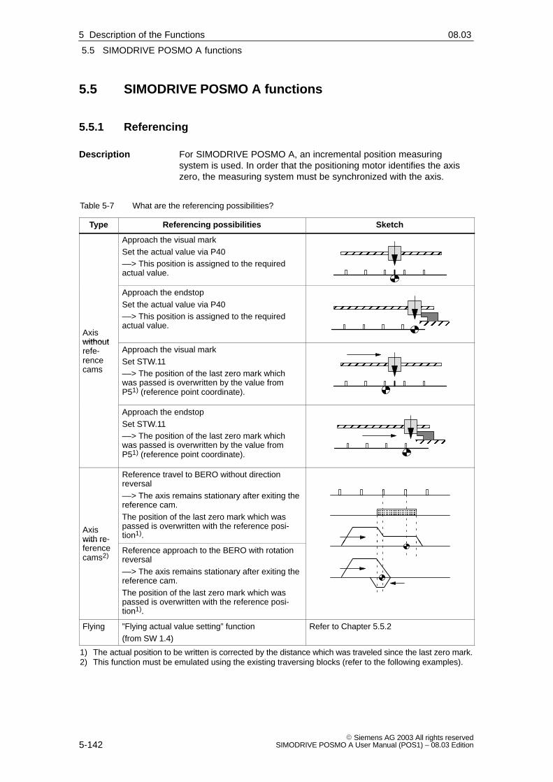
5
5.5 SIMODRIVE POSMO A functions
5-142� Siemens AG 2003 All rights reserved
SIMODRIVE POSMO A User Manual (POS1) – 08.03 Edition
5.5 SIMODRIVE POSMO A functions
5.5.1 Referencing
For SIMODRIVE POSMO A, an incremental position measuringsystem is used. In order that the positioning motor identifies the axiszero, the measuring system must be synchronized with the axis.
Table 5-7 What are the referencing possibilities?
Type Referencing possibilities Sketch
Approach the visual markSet the actual value via P40––> This position is assigned to the requiredactual value.
ÏÏÏÏÏÏÏÏ
Axiswithout
Approach the endstopSet the actual value via P40––> This position is assigned to the requiredactual value. ÏÏÏ
ÏÏÏÏÏÏÏÏ
withoutrefe-rencecams
Approach the visual markSet STW.11––> The position of the last zero mark whichwas passed is overwritten by the value fromP51) (reference point coordinate).
ÏÏÏÏÏÏÏÏ
Approach the endstopSet STW.11––> The position of the last zero mark whichwas passed is overwritten by the value fromP51) (reference point coordinate).
ÏÏÏÏÏÏ
ÏÏÏÏÏÏÏÏ
Axiswith re-ference
Reference travel to BERO without directionreversal––> The axis remains stationary after exiting thereference cam.The position of the last zero mark which waspassed is overwritten with the reference posi-tion1).
ÄÄÄÄÄÄÄÄ
with re-ferencecams2)
Reference approach to the BERO with rotationreversal––> The axis remains stationary after exiting thereference cam.The position of the last zero mark which waspassed is overwritten with the reference posi-tion1).
Flying ”Flying actual value setting” function(from SW 1.4)
Refer to Chapter 5.5.2
1) The actual position to be written is corrected by the distance which was traveled since the last zero mark.2) This function must be emulated using the existing traversing blocks (refer to the following examples).
Description
5 Description of the Functions 02.9908.03

5
5.5 SIMODRIVE POSMO A functions
5-143� Siemens AG 2003 All rights reservedSIMODRIVE POSMO A User Manual (POS1) – 08.03 Edition
The following limitations apply when referencing:
� The positioning motor supplies the following zero marks:
– 75 W motor ––> 4 zero marks per motor revolution
– 300 W motor ––> 1 zero mark per motor revolution
� The position of the zero mark, which was last recognized, is over-written with the value in P5 (reference point coordinate) by settingSTW.11 (start referencing/stop referencing). The actual position to be written is corrected by the distance whichwas traveled since the last zero mark.
Prerequisite:The axis must be at a standstill and be in closed–loop control.
If the axis is moving, then the value is not accepted and an alarm isoutput.
� If the motor was not moved after being powered up, i.e. a zero markhas still not been passed, and therefore there is no valid position fora zero mark, then referencing is rejected and a warning output. The ”referenced” status is lost.
� Generally, the following is valid:
ZSW.11 (reference point set/no reference point set) is used to dis-play whether an axis is referenced.
� Resetting the status ”reference point set” (from SW 1.4)
For a stationary axis that has been referenced, the ”no referencepoint set” state is re–established by writing a 0 into P98.
� The following applies for a non–referenced axis:
– No blocks with absolute position data are executed.
– The axis zero of the axis is the position after the drive has beenpowered up.
!Warning
For non–referenced axes, the software limit switches are notmonitored.
Suitable measures must be implemented in the system (e.g. hardwarelimit switches) in order to avoid injury to personnel and damage to themachine.
Limitations whenreferencing
5 Description of the Functions02.9904.01

5
5.5 SIMODRIVE POSMO A functions
5-144� Siemens AG 2003 All rights reserved
SIMODRIVE POSMO A User Manual (POS1) – 08.03 Edition
The SIMODRIVE POSMO A positioning motor can be referenced at aspecific axis position by writing the required actual value into P40 (posi-tion actual value).
For a stationary axis, this position is accepted as position actual value,and after this, SIMODRIVE POSMO A is considered to have been refe-renced.
� Move, e.g. using ”jogging” to the required axis position.
� Reference the positioning motor by writing the actual value, valid forthis axis position, into P40 (position actual value).
Note
For ”set actual value”, the same conditions must exist as whenreferencing, i.e. the drive must be closed–loop controlled and bestationary.
The reference position can be set to a zero mark using the traversingblock as shown in the following program example.
Example:
� Program control word (PSW) = 515dec (10 0000 0011bin)P80:x
Bit 9 = 1 ––> set reference positionBit 1 = 1 ––> relativeBit 0 = 1 ––> enter position and velocity (closed–loop pos. contr.)
� Target position = 100.0 mm P81:x
� Velocity = 100 % P82:x
� Acceleration = 100 % P83:x
� Time = 0 ms P84:x
� MeldPos = 50.0 P85:x
For this traversing block, the axis traverses through 100 mm relative. Atthe end of the block, the setting value for the reference position is readfrom ”MeldPos”, in order to correct the distance moved since the lastzero mark. The axis is then referenced.
This function corresponds to referencing an axis with reference cams(refer to Table 5-7).
The actual value can be set via a traversing block as shown in theabove program example.
At the end of the block, the position, saved in ”MeldPos” becomes thenew actual position of the drive.
Setting actualvalue by writinginto P40
Setting thereferencingposition to thezero mark usingthe traversingblock (from SW 1.4)
Setting the actualvalue using thetraversing block(before SW 1.4)
5 Description of the Functions 02.9904.01

5
5.5 SIMODRIVE POSMO A functions
5-145� Siemens AG 2003 All rights reservedSIMODRIVE POSMO A User Manual (POS1) – 08.03 Edition
The ”traverse to fixed endstop” function can be used as follows forreferencing:
� Set the current to a permissible value for the fixed endstop.
– P28 (max. current) = ”required current”
– P16 (max. overcurrent) = ”required overcurrent”
� Suppress the ”speed controller at the endstop ” fault.
– P30.0 = ”1” ”Speed controller at the endstop” fault––> is redefined to become a warning
� Traverse to the fixed endstop by jogging
When the endstop is reached, it is displayed as follows:
– ZSW.7 = ”1” ––> means ”warning effective”
and
– P953.7 = ”1” ––> means ”speed controller at its endstop”
� Cancel jogging
� Set a valid position actual value for the fixed endstop position
– Write a valid position actual value into P40
P40 = ”requested actual value” Position actual value
or
– Assign a valid position actual value from P5
The position of the last zero mark is set to the value in P5 (refe-rence point coordinate) by ”start referencing” and ”stop referen-cing” (STW.11).
The actual position to be written is corrected by the distancewhich was traveled since the last zero mark.
Set the ”stop referencing” depending on ”reference point set”(ZSW.11).
Reader’s note
”Traverse to fixed endstop” function refer to Chapter 5.5.3
Referenceapproach with”traverse tofixed endstop”
5 Description of the Functions02.99

5
5.5 SIMODRIVE POSMO A functions
5-146� Siemens AG 2003 All rights reserved
SIMODRIVE POSMO A User Manual (POS1) – 08.03 Edition
The reference point approach is executed via program. The axis traver-ses without direction of reversal dependent on the reference cam sig-nal.
Zero marks
Reference camsignal
(e.g. from BERO)
Traversing profile
Reference mark
ÄÄÄÄÄÄÄÄÄÄ
Reference cams
Fig. 5-5 Reference travel to BERO without direction reversal
Prerequisites:
� Connect the reference cam signal to terminal 1(X5, I/Q1, refer to Chapter 2.3)
� Define terminal 1 as input and directly transfer the input terminalsignal into the start byte(e.g. start byte bit 7 ––> P31 = 25, refer to Chapter 5.5.10)
Program the following traversing program (example):
� Program block (e.g. block 13)
– SMStart bit 7 as start condition
– Program control word (PSW) = 224dec (00 1110 0000Bin) (E0hex)(closed–loop speed controlled, with approximate positioning, withnegated start byte, skip if the start byte is not fulfilled)
– Speed e.g. 20 % (= approach velocity)
– Acceleration 100 %
� Program block (e.g. block 14)
– SMStart bit 7 as start condition
– Program control word (PSW)= 384dec (01 1000 0000Bin) (180hex)
(closed–loop speed controlled without negated start byte)
– Speed e.g. 5 % (= shutdown velocity)
– Acceleration 100 %
– Program end when the end of the block is reached
� Start program
As soon as ZSW.14 = ”0” (outside traversing block) is signaled, thereference point can be set with STW.11 (start referencing / stop re-ferencing).
Referenceapproach to aBERO proximityswitch without direction reversal
5 Description of the Functions 02.99

5
5.5 SIMODRIVE POSMO A functions
5-147� Siemens AG 2003 All rights reservedSIMODRIVE POSMO A User Manual (POS1) – 08.03 Edition
� Set reference coordinate
The position of the last zero mark before the end of the second pro-gram block is therefore set to the value in P5 (reference point coor-dinate).
Set simplified reference position (from SW 1.4)
The drive is automatically referenced when the above traversing pro-gram is run if the following is specified in the second block:
� P85:14 (signal position for block 14)= set ”required reference point” coordinate
� Set PSW.9 (set reference position) to 1
In this case, the last part of the example above is eliminated.
Note
� If the direction of rotation is reversed in both traversing blocks(negative velocity), the reference point approach is executed in theopposite direction.
� In order to select the last zero mark at the reference cam asreference point coordinate, the shutdown velocity should beselected low enough, so that when braking after leaving the cam,no other zero marks are passed.
� Reference cam length
A cam length should be selected so that the axis brakes from theapproach velocity to the shutdown velocity while still at the cam.
5 Description of the Functions02.9904.01

5
5.5 SIMODRIVE POSMO A functions
5-148� Siemens AG 2003 All rights reserved
SIMODRIVE POSMO A User Manual (POS1) – 08.03 Edition
The reference point approach is executed via program. The axis traver-ses with direction reversal depending on the reference cam signal.
Zero marks
Reference camsignal
(e.g. from BERO)
Traversing profile
Reference mark
ÄÄÄÄÄReference cams
Fig. 5-6 Reference approach to the BERO with direction reversal
Prerequisites:
� Connect the reference cam signal to terminal 1(X5, I/Q1, refer to Chapter 2.3)
� Define terminal 1 as input and directly transfer the input terminalsignal into the start byte(e.g. start byte bit 7 ––> P31 = 25, refer to Chapter 5.5.10)
Program the following traversing program (example):
� Program block (e.g. block 13)
– SMStart bit 7 as start condition
– Program control word (PSW) = 224dec (00 1110 0000bin) (E0hex)(closed–loop speed controlled, with approximate positioning, withnegated start byte, skip if the start byte is not fulfilled)
– Speed e.g. 20 % (= approach velocity)
– Acceleration 100 %
� Program block (e.g. block 14)
– SMStart bit 7 as start condition
– Program control word (PSW)= 384dec (01 1000 0000bin) (180hex)
(closed–loop speed controlled without negated start byte)
– Speed e.g. –5 %(= shutdown velocity with direction reversal)
– Acceleration 100 %
– Program end when the end of the block is reached
� Start program
As soon as ZSW.14 = ”0” (outside traversing block) is signaled, thereference point can be set with STW.11 (start referencing / stop re-ferencing).
Referenceapproach to aBERO proximityswitch withdirection reversal
5 Description of the Functions 02.99

5
5.5 SIMODRIVE POSMO A functions
5-149� Siemens AG 2003 All rights reservedSIMODRIVE POSMO A User Manual (POS1) – 08.03 Edition
� Set reference coordinate
The position of the last zero mark before the end of the second pro-gram block is therefore set to the value in P5 (reference point coor-dinate).
Set simplified reference position (from SW 1.4)
The drive is automatically referenced when the above traversing pro-gram is run if the following is specified in the second block:
� P85:14 (signal position for block 14)= set ”required reference point” coordinate
� Set PSW.9 (set reference position) to ”1”
In this particular case, the last section in the example above is eliminated.
Note
� If the direction of rotation is reversed in both traversing blocks, thereference point approach is executed in the opposite direction.
� In order to select the last zero mark at the reference cam asreference point coordinate, the shutdown velocity should beselected low enough, so that when braking after leaving the cam,no other zero marks are passed.
� Reference cam length
The cam length should be selected, so that the axis brakes fromthe approach velocity to standstill while still at the cam.
� Position of the reference cam
If the reference cam is not favorably mounted, when the traversingprogram starts from the cam, a different reference point can beobtained than when starting in front of the reference cam.
Remedy: The referencing program should be modified so that the axis initially moves away from the cam.
5 Description of the Functions02.9904.0108.03

5
5.5 SIMODRIVE POSMO A functions
5-150� Siemens AG 2003 All rights reserved
SIMODRIVE POSMO A User Manual (POS1) – 08.03 Edition
Before SW 1.2, the following is valid:
If a referenced axis is switched-out, then it is still referenced after it hasbeen switched–in again if it was not moved when it was switched-out(refer to ZSW.13 = 0).
The following is valid from SW 1.2:
Another behavior when the axis is switched–in again can be set usingP56 (operating options).
––> refer to Chapter 5.6.2 under P56
For axes with extremely low friction, it should be noted that a motor canmove into a preferred position when it is powered–down. Under worstcase conditions, this uncontrolled equalization motion is 11 degrees atthe motor shaft.
If the electronics power supply is simultaneously switched–out, thenthis drive motion is not detected.
Possible counter measures include:
� If there are separate electronics and load power supplies then theelectronics power supply must be switched–off with a delay after theload power supply has been switched off.
� The pulses should be cancelled before switching–off the load andelectronics power supply (e.g. using STW.1 = 0).
Referenced axiswhen powering upagain
Behavior whenpowering–down
5 Description of the Functions 02.9902.0004.01

5
5.5 SIMODRIVE POSMO A functions
5-151� Siemens AG 2003 All rights reservedSIMODRIVE POSMO A User Manual (POS1) – 08.03 Edition
5.5.2 Flying measurement/actual value setting (from SW 1.4)
Note
For the ”flying measurement / actual value setting” function, digitalinput 1 is updated in a 125 µs grid.
While the motor is braking, a 0/1 edge is ineffective and the ”flyingmeasurement/actual value setting” function is not executed.
The positioning motor can be used for test purposes using the ”flyingmeasurement” function.
v
t
1
0
Block 18
Block 19
� Brakes along the braking ramp
� Block change with delete distance to go
� The position value is written into P62(measuring position)
� Continue the program
t
Input signal”flyingmeasurement/actualvalue setting”
What happens for a 0/1 signaledge?
� Traverses as programmed in the block
� The measured value in P62 (measuring position) isnot updatedNo input signal detected?
Fig. 5-7 Example: Flying measurement
What should be done?The following has to be done in order to use the ”flying measurement”function.
1. Connect the signal transmitter to digital input 1 (X5 terminal I/Q1)
––> the signal transmitter must be high active
––> refer to Chapter 2.3 and 2.4
2. Assign digital input 1 to the ”flying measurement/actual value set-ting” function
––> in SimoCom A under the tab ”Par” and entry ”Digital inputs/outputs”
––> by setting SIMATIC S7 P31 to 27
3. Program the traversing block, activating the ”flying measurement”function
––> set PSW.11 to ”1”
4. Read the measured value after a 0/1 signal edge has been detected
––> P62 (measuring position) = measured position value
Flyingmeasurement(from SW 1.4)
5 Description of the Functions02.9908.02

5
5.5 SIMODRIVE POSMO A functions
5-152� Siemens AG 2003 All rights reserved
SIMODRIVE POSMO A User Manual (POS1) – 08.03 Edition
Position–controlled traversing motion to the cam / BERO withstop if a cam was not detected.
v
t
1
0
Block 9
Block 11
� Brakes along the braking ramp� Block change with delete distance to go� The position value is written into P62
(measuring position)� Continue the program (here: block 10)
t
Input signal”Flyingmeasurement”
What happens for a 0/1 signaledge?
� The drive changes after the traversing distance, specifiedin block 9, to block 10.
� The drive stops because this does not contain a startcondition. This means, that in comparison to aspeed–controlled solution, it can be ensured that the drivedoes not endlessly move if the cam / BERO is either notwired at all or is defective.
What happens if an edge isnot detected?
Block 10
v
t
1
0
Block 9
t
Input signal”Flyingmeasurement”
Block 10
Fig. 5-8 Example: Position–controlled traversing motion to cam/BERO with stop
Using a special configuration of the traversing blocks, the ”flyingmeasurement” function can be executed so that the drive stops if theBERO/cam is not reached within a specified maximum distance. In thisparticular case, the program is still active and must be interrupted usinga stop command.
In this case, the first program block selected is – e.g. block No. 9.
What should be done?
The following has to be done in order to use the ”flying measurement”function?
1. Connect the signal transmitter to digital input 1 (X5 terminal I/Q1)
––> the signal transmitter must be high active
––> refer to Chapter 2.3 and 2.4
Example
5 Description of the Functions 02.9908.0208.02

5
5.5 SIMODRIVE POSMO A functions
5-153� Siemens AG 2003 All rights reservedSIMODRIVE POSMO A User Manual (POS1) – 08.03 Edition
2. Assign digital input 1 to the function ”transfer value directly in thestart byte (bit 7)”
––> in SimoCom A under the tab ”Par” and entry ”Digital inputs/outputs”
––> by setting SIMATIC S7 P0031 to 25
3. Program the traversing block (e.g. block No. 9) as follows
––> in the SimoCom A under the ”Par” tab and entry”Traversing blocks”
––> select the ”relative” traversing type (set SIMATIC S7 P0080:9 bit 0 to 0 via the SIMATIC S7
––> enter the target position (max. distance to the cam)In this case, the sign of the distance specifies whether the signal is in the positive or negative traversing direction to the actual value.(if the drive moved through this distance, then thedrive stops and changes to the following traversing block.)
––> select ”Continue flying” block change enable (set SIMATIC S7 P0080:9 bit 5 to 1 via the SIMATIC S7
––> select PSW ”flying measurement: active” in the PSW selection box (set SIMATIC S7 P0080:9 bit 10 to 1 via the SIMATIC S7
4. Then program the following traversing block as follows (e.g. blockNo. 10)
––> select the ”relative” traversing type (set SIMATIC S7 P0080:10 bit 0 to 0 via the SIMATIC S7
––> set position, velocity to 0(set P0081:10 to 0; P0082:10 to 0 via the SIMATIC S7)
––> select ”continue flying” block change enable (set SIMATIC S7 P0080:10 bit 5 to 1 via the SIMATIC S7
––> in the selection box PSW check that ”SM start type” is in thedefault setting ”SM start type: wait” (bit=0) (set SIMATIC S7 P0080:10 bit 7 to 0 via the SIMATIC S7
––> in the selection box PSW, select ”flying measurement: active”(set SIMATIC S7 P0080:10 bit 10 to 1 via the SIMATIC S7This means that a measurement is made if the cam ispassed during the braking phase.
––> SM/MM - set start bit 15 to 1(set P0086:10 bit 15 to 1 via the SIMATIC S7)This means that the traversing block is only executedif the BERO/cam was actually reached.
The program can be started under the ”Control” tab, entry ”Automatic”.
The program with the number of the start block must be selected to dothis.
5 Description of the Functions02.9908.02
5
5.5 SIMODRIVE POSMO A functions
5-154� Siemens AG 2003 All rights reserved
SIMODRIVE POSMO A User Manual (POS1) – 08.03 Edition
Possible program sequence:
1. The following happens if the BERO/cam in block 9 signals a 0/1edge at the digital input before the braking phase:
– The motor brakes along the braking ramp
– A block change with delete distance to go is initiated
– The measured position value is written into P0062 (measuringposition)
– The program continues with block 10. As a result of the camfeedback signal via start byte bit 7, this immediately receives thestart condition, specified in the SM/MM start and changes toblock 11.
2. The following happens if the BERO/cam in block 9 did not provide asignal at the digital input before the braking phase:
– The motor brakes along the braking ramp and then changes,after this has been initiated, to traversing block 10
– If, the cam still outputs a signal in the braking phase, then themeasuring function in block 10 is executed and a change ismade to traversing block 11.
– If a cam does not output a signal in the braking phase, then tra-versing block 10 does not have a valid start condition and there-fore goes into the state ”wait for start condition”.
In this case, the program has not been completed. When the camsignal or BERO outputs a signal via the digital input, the program withblock 11 is continued without a position having been measured.
5 Description of the Functions 02.9908.02

5
5.5 SIMODRIVE POSMO A functions
5-155� Siemens AG 2003 All rights reservedSIMODRIVE POSMO A User Manual (POS1) – 08.03 Edition
While a block is being processed, the actual value can be set using a0/1 signal edge at input terminal 1.
The dimension system is then re–synchronized. The following blocksare then executed in the new reference system.
v
t
1
0
Block 13
Block 14
� Brakes along the braking ramp
� Block change with delete distance to go
� The actual value is set to the position in P85:28 (signalposition)
––> the new reference system applies from this position
t
Input signal”Flyingmeasurement/actualvalue setting”
What happens for a 0/1 signaledge?
� Traverses as programmed in the blockNo input signal detected?
Fig. 5-9 Example: Flying actual value setting
What should be done?
The following has to be done in order to use the ”flying actual valuesetting” function?
1. Connect the signal transmitter to digital input 1 (X5 terminal I/Q1)
––> the signal transmitter must be high active
––> refer to Chapter 2.3 and 2.4
2. Assign digital input 1 to the ”flying measurement/actual value set-ting” function
––> in the SimoCom A under the tab ”Par” and entry ”Digital inputs/outputs”
––> by setting SIMATIC S7 P31 to 27
3. Program the traversing block, activating the ”flying actual value set-ting” function
––> set PSW.10 to ”1”
4. Enter the value for ”actual value setting”
––> P85:28 (signaled position) = required actual value
Flying actual valuesetting(from SW 1.4)
5 Description of the Functions02.9904.01

5
5.5 SIMODRIVE POSMO A functions
5-156� Siemens AG 2003 All rights reserved
SIMODRIVE POSMO A User Manual (POS1) – 08.03 Edition
Flying actual value setting followed by absolute positioning (fromSW 1.4)
The following example shows how the actual value can be set flyingwhen approaching a BERO/cam and then an absolute or relative posi-tioning operation can be started.
However, for safety reasons, positioning should be interrupted if neitherBERO nor cam were detected within a specified maximum distance.
In this case, the first program block selected is – e.g. block No. 9.
1. Connect the signal transmitter to digital input 1 (X5 terminal I/Q1)
––> the signal transmitter must be high active
––> refer to Chapter 2.3 and 2.4
2. Assign digital input 1 to the ”flying measurement/actual value set-ting” function
––> in the SimoCom A under the tab ”Par” and entry ”Digital inputs/outputs”
––> by setting SIMATIC S7 P31 to 27
3. Program the traversing block (e.g. Block No. 9) as follows
––> in SimoCom A under the ”Par” tab and entry”Traversing blocks”
––> select the ”relative” position (PSW.0 = 1)
––> select the ”flying” block change enable(set SIMATIC S7 P0080:9 bit 5 to 1 via the SIMATIC S7
––> enter the target position (max. distance to the cam)The sign of the distance specifies whether the signal is in thepositive or negative traversing direction with respect to the current actual value.
––> in the selection box PSW, select ”flying actual value setting: active” (PSW.10 = 1)
––> enter the required actual value in the signaling position.
If a relative positioning to the new reference point is then to be carried–out in block No. 10, then the block change enable condition in block No.9 must be programmed for ”continue flying”. The block is now changedwith delete distance to go.
The traversing block to find the signals has now been programmed
If the signal is detected within the maximum distance via the digital in-put, then the actual position is set to the required actual value and thedrive goes into the state ”reference point set” (ZSW1.11=1).
If the subsequent traversing blocks are parameterized as absoluteblocks, then these are only executed if the ”flying actual value setting”in block No. 9 was successful.
Example
5 Description of the Functions 02.9908.02

5
5.5 SIMODRIVE POSMO A functions
5-157� Siemens AG 2003 All rights reservedSIMODRIVE POSMO A User Manual (POS1) – 08.03 Edition
However, in this case, it is necessary that the drive is in the state ”refe-rence point is not set” (ZSW1.11=0) before the start of traversing blockNo. 9.
If the drive was already referenced when block No. 9 was started, anda signal was not found, then it is possible that the absolute blocks wereexecuted in the incorrect reference system. This means that before thestart of the program, the POSMO A must always be ”de–referenced”(P98 = 0).
5 Description of the Functions02.99
5
5.5 SIMODRIVE POSMO A functions
5-158� Siemens AG 2003 All rights reserved
SIMODRIVE POSMO A User Manual (POS1) – 08.03 Edition
5.5.3 Traversing to a fixed endstop
A linear or rotary axis can be moved in the closed–loop speed control-led mode to a fixed endstop using the ”traverse to fixed endstop” func-tion. When a fixed endstop is reached, then the defined torque/force isestablished.
This feature can be used, e.g. as follows:
� To clamp workpieces (e.g. to press the spindle sleeve against theworkpiece)
� To approach the mechanical reference point (refer to Chapter 5.5.1)
The following has to be done to traverse to a fixed endstop:
� Set the current to a permissible value for a fixed endstop
– P28 (max. current) = ”required current”
– P16 (max. overcurrent) = ”required overcurrent”
� Suppress the ”speed controller at the endstop” fault
– P30.0 = ”1” ”speed controller at the endstop” fault––> is redefined to become a warning
� Move to the fixed endstop closed–loop speed–controlled (PSW.0 =”0” or jogging)
When the endstop is reached, it is displayed as follows:
– ZSW.7 = ”1” ––> means ”warning present”
and
– P953.7 = ”1” ––> means ”speed controller at the endstop”
� Stop traversing
The following has to be observed:
Note
� The ”traverse to fixed endstop” function can only be practically usedwhen traversing in the closed–loop speed controlled mode (PSW.0= ”0” or jogging).
For closed–loop position controlled techniques (PSW.0 = ”1”), the”fixed endstop reached” state can only be exited using OFFcommands.
� Limit P28 and P16 to values, at which torques significantly lowerthan the limiting torque occur at the gearbox output.
P28 maximum current
P16 maximum overcurrent
� Limit the traversing velocity to a value which is significantly belowthe maximum velocity at the rated speed.
Description
What should bedone?
What has to beobserved?
5 Description of the Functions 02.9904.01

5
5.5 SIMODRIVE POSMO A functions
5-159� Siemens AG 2003 All rights reservedSIMODRIVE POSMO A User Manual (POS1) – 08.03 Edition
5.5.4 Rotary axis
A rotary axis is parameterized using the following parameters:
� P1 axis type e.g. = 360
� P2 travel per gearbox revolution e.g. = 360
� P3 gearbox step–down factor e.g. = 18
� P4 dimension units e.g. = 1
Example (refer to Chapter 3.3):
A rotary axis with modulo 360 and dimension units of degrees is para-meterized with these typical values.
The traversing characteristics of a rotary axis are dependent on whichpositioning type has been programmed – either ABSOLUTE or RELA-TIVE.
� Absolute motion
– Target position
The target position is programmed in the traversing block usingP81:28 and is executed, modulo–corrected.
Example:
P81:4 = 520 ––> for modulo 360, the axis is positioned to 160
– Velocity and traversing direction
The velocity and traversing direction is programmed in the tra-versing block using P82:28.
Velocity: Absolute value of P82:28
Traversing direction: Sign of P82:28+: ––> positive direction–: ––> negative direction
Traverse through the shortest distance: PSW.12 = ”1” (from SW 1.4)
� Relative motion
– Target position and traversing direction
The target position is programmed in the traversing block usingP81:28 and is not executed, modulo–corrected.
P81:28 > 0 ––> positive traversing directionP81:28 < 0 ––> negative traversing direction
Examples:
P81:4 = 520 ––> the axis moves in the positive direction through 520 P81:4 = –10 ––> the axis moves in the negative direction through 10
– Velocity
Velocity: is entered via P82:28
Parameterizingrotary axes
Programming
5 Description of the Functions02.9904.01

5
5.5 SIMODRIVE POSMO A functions
5-160� Siemens AG 2003 All rights reserved
SIMODRIVE POSMO A User Manual (POS1) – 08.03 Edition
Positioning type = ABSOLUTE
Example 1 (PSW.12 = ”0”):
P81:4 = 315
P82:4 = –100
––> Traverse with 100 % to 315� negative
Example 2 (PSW.12 = ”0”):
P81:4 = 315
P82:4 = 100
––> Traverse with 100 % to 315� positive
Positioning type = RELATIVE
Example 1:
P81:4 = –90
P82:4 = 100
––> Traverse with 100 % through 90� negative
Example 2:
P81:4 = 135
P82:4 = 100
––> Traverse with 100 % through 135 ���������
45°
90°
135°
180°
225°
270°
315°
0°
45°
90°
135°
180°
225°
270°
315°
0° Example 1
Example 2
Start Start
Example 1
Example 2
Fig. 5-10 Example: Programming rotary axes
The following should be observed for the signaling position:
� Before SW 1.3 the following applies:
– The drive has precisely one zero position (refer to Chapter5.5.1). The signal position is viewed, referred to this position.
– A modulo evaluation is not made.
� The following is valid from SW 1.3:
– The signal position is saved, evaluated as modulo value
The software limit switches act the same as for a linear axis.
� P6 software limit switch, start (refer to Chapter 5.6.2)
� P7 software limit switch, end
The software limit switches are de–activated with P6 = P7.
Signaling position(P85:28)
Signaling position(P55)
Software limitswitch
5 Description of the Functions 02.9904.01

5
5.5 SIMODRIVE POSMO A functions
5-161� Siemens AG 2003 All rights reservedSIMODRIVE POSMO A User Manual (POS1) – 08.03 Edition
5.5.5 Backlash compensation and correction direction (from SW 1.4)
When an indirect measuring system is used (position measuring enco-der at the motor), at each direction reversal, the mechanical play is firsttraveled through before the axis moves.
For this measuring system, mechanical play falsifies the traversingdistance. This is because at direction reversal, the axis moves too littleby the absolute value of the play.
After entering the backlash compensation and the correction direction,at each direction reversal, the axis actual value is corrected dependingon the actual traversing direction.
Backlash
Table
ÏÏÏÏÏÏ
ÏÏÏÏÏÏÏÏÏÏ
For a direction reversal, the encoder actual value leads theactual value (table) ––> the table does not traverse far enough
M Motor
G EncoderMG
Fig. 5-11 Backlash
The following procedure is recommended to determine the backlash ofan axis:
� Traverse the axis e.g. in the positive direction – take up the play
� Mount a dial gauge on the axis mechanical system
� Note down the actual position 1 (read P40)
� Traverse the axis in the negative direction until axis movement canbe detected at the dial gauge
� Note down the actual position 2 (read P40)
The backlash is obtained from the difference between actual position 1and actual position 2.
Description
Example: Determining thebacklash
5 Description of the Functions02.9904.01

5
5.5 SIMODRIVE POSMO A functions
5-162� Siemens AG 2003 All rights reserved
SIMODRIVE POSMO A User Manual (POS1) – 08.03 Edition
The correction direction of the backlash compensation is defined asfollows using the sign of P15:
P15 = positive ––> positive correction direction
The following applies when first traversing after power–on:
� Traversing in the positive direction – backlash is corrected
� Traversing in the negative direction– backlash is not corrected
P15 = negative––> negative correction direction
The following applies when first traversing after power–on:
� Traversing in the positive direction – backlash is not corrected
� Traversing in the negative direction– backlash is corrected
Note
The following applies when entering a value in P15 (backlashcompensation):
Depending on the sign of P15, the actual value can be immediatelyshifted by the value entered for the backlash. The backlash valuebecomes effective immediately and is taken into account in the display.
P15 Backlash compensation
Correctiondirection (fromSW 1.4)
Parameter(refer to Chapter5.6.2)
5 Description of the Functions 02.9904.01

5
5.5 SIMODRIVE POSMO A functions
5-163� Siemens AG 2003 All rights reservedSIMODRIVE POSMO A User Manual (POS1) – 08.03 Edition
5.5.6 Jerk limiting
Acceleration and deceleration are step–like if jerk limiting is not used.
Using jerk limiting, a ramp–type increase can be parameterized for bothquantities, so that approach and braking are ”smooth” (jerk–limited).
Jerk limiting can be used, e.g. for positioning tasks using liquids or ge-nerally to reduce the mechanical stressing on an axis.
r
a
v
t
t
t
P22
P22
P23 = TR [s] =a [mm/s2]
r [mm/s3]
a: Acceleration
r: Jerk
t: Time
TR: Jerk time
v: Velocity
P23
Fig. 5-12 Jerk limiting
P23 Jerk time constant
P22 Maximum acceleration
Description
Applications
Parameters(refer to Chapter5.6.2)
5 Description of the Functions02.99

5
5.5 SIMODRIVE POSMO A functions
5-164� Siemens AG 2003 All rights reserved
SIMODRIVE POSMO A User Manual (POS1) – 08.03 Edition
5.5.7 Changeover, metric/inch
When changing over between mm and inch and vice versa, all existingvalues, dependent on length measurements, are automatically chan-ged.
All of the following inputs and outputs are handled in the new dimen-sion units.
P4 dimension unit
5.5.8 Reversing the control sense (from SW 1.3)
Before SW 1.3 the following applies:
The direction of rotation of the motor shaft depends on whether it tra-verses in the positive or negative direction and cannot be changed.
From SW 1.3 and after, the following applies:
The direction of rotation of the motor shaft can be set as required, de-pendent on whether traversing in the positive or negative directionusing P3.
Table 5-8 Traversing and direction of rotation of the motor shaft
Traversing direction Rotation of the motor shaftwhen viewing the motor shaft drive out end
P3 = positive P3 = negative(from SW 1.3)
Traversing in the posi-tive direction
Clockwise Counter–clockwise
Traversing in the nega-tive direction
Counter–clockwise Clockwise
P3 Gearbox ratio
Description
Parameter(refer to Chapter5.6.2)
Description
Parameter(refer to Chapter5.6.2)
5 Description of the Functions 02.9904.01

5
5.5 SIMODRIVE POSMO A functions
5-165� Siemens AG 2003 All rights reservedSIMODRIVE POSMO A User Manual (POS1) – 08.03 Edition
5.5.9 Standstill monitoring
Using the standstill monitoring function, the system can detect whenthe axis leaves the target position (under load, for hanging axes, etc.).
The monitoring time (P13) is started after the motion block has beencompleted (position reference value = target setpoint).
After the monitoring time (P13) has expired, it is cyclically monitored asto whether the actual axis position remains within the standstill range(P14) around the target position.
Objective: Continually check whether the position of the axis is also maintained.
t
Targetposition
Positionvalue
x
Target range (P11)
Position-referencevalue
Positionactualvalue
Standstill range(P14)
Monitoring time (P13)
The standstill monitoring iscyclically evaluated from here
Fig. 5-13 Standstill monitoring
When the standstill monitoring responds, an appropriate fault is signaled.
When the next block is started, the standstill monitoring is disabled.
P11 target range
P13 monitoring time
P14 standstill range
Description
Mode of operation
Fault case
Switching–off
Parameter(refer to Chapter5.6.2)
5 Description of the Functions02.9902.00

5
5.5 SIMODRIVE POSMO A functions
5-166� Siemens AG 2003 All rights reserved
SIMODRIVE POSMO A User Manual (POS1) – 08.03 Edition
5.5.10 Digital inputs/outputs
For SIMODRIVE POSMO A, there are 2 freely–parameterizable input/output terminals. The function of a terminal is defined by appropriatelyparameterizing it.
� Designation of the input/output terminals (refer to Chapter 2.3.1)
– X5 terminal I/Q1 Terminal 1
– X5 terminal I/Q2 Terminal 2
� Parameterization of the input/output terminals (refer to Chapter5.6.2)
– P31 function, terminal 1
– P32 function, terminal 2
Note
The digital inputs/outputs are updated every 10 ms.
Reader’s note
List of function numbers for digital inputs/outputs?
––> refer to Chapter 5.6.2 under P31 (function, terminal 1)
The list is valid for terminals 1 and 2.
Description
5 Description of the Functions 02.9904.01

5
5.5 SIMODRIVE POSMO A functions
5-167� Siemens AG 2003 All rights reservedSIMODRIVE POSMO A User Manual (POS1) – 08.03 Edition
The following rules apply for allocating functions:
� The hardware inputs/outputs are high active.
� Rules for input terminals
– A hardware terminal has a higher priority than a PROFIBUS signal
If a terminal is parameterized as input, then this terminal comple-tely assumes the function, i.e. a control signal, with the samesignificance, received via PROFIBUS, is ignored.
Exceptions:
If a terminal is parameterized with a value 100, 101 or 102 (OFF1, OFF 2, OFF 3 logically AND’ed with the terminal), then thefollowing applies:The signals are only present if they are set from the terminal andfrom the PROFIBUS–DP master (this is a safety function).
– If the 2 input terminals are assigned the same function number,then terminal 2 has priority.
!Warning
The appropriate signals from PROFIBUS DP are ignored!
� Rules for output terminals
– Output signals are output via a terminal without influencingPROFIBUS communications.
– Inversion:
The outputs can be inverted by adding 128 to the values speci-fied in the function list.
Example:
The ”reference point set” signal should be output inverted viaterminal 1.
––> parameter value = 74 + 128 = 202 (refer to Chapter 5.6.2)––> set P31 to 202
––> a signal is set at the terminal if SIMODRIVE POSMO A isnot referenced.
� Signaling the terminal state (from SW 1.4)
The actual state of the terminal can be displayed in the feedbacksignal byte (RMB) by adding 256 to the value specified in the func-tion list.
RMB.6 ––> state of terminal 1
RMB.7 ––> state of terminal 2
Feedback signal byte (RMB)refer to Chapter 4.2 and 4.2.2
Control
5 Description of the Functions02.9904.01

5
5.5 SIMODRIVE POSMO A functions
5-168� Siemens AG 2003 All rights reserved
SIMODRIVE POSMO A User Manual (POS1) – 08.03 Edition
5.5.11 Jogging without PROFIBUS and parameterization (from SW 1.4)
The positioning motor can be immediately traversed in the jog modeusing this function via the terminals without PROFIBUS communica-tions and without additional parameterization.
If PROFIBUS node address 0 or 127 is detected when the positioningmotor is powered–up (all address switches are either OFF or ON), thenthe following is executed:
� The factory default for the parameters is downloaded.
� Parameters which were possibly changed beforehand are ignored.
� Jogging is selected with the following data:
– P100 = 17471dec ––> simulation of the control word
– P31 = 4 function, terminal 1 <––> jogging –
– P32 = 5 function, terminal 2 <––> jogging +
These changes are not saved.
The following has to be done to be able to use the positioning motor inthe jogging mode without parameterization and PROFIBUS:
1. Connect the load power supply and both digital inputs
––> refer to Chapter 2.3 and 2.4
2. Set the PROFIBUS node address to 0 or 127
––> refer to Chapter 2.3.1 and Table 2-3
!Caution
For reliable operation, it is absolutely necessary that the motor iscorrectly mounted and connected up (refer to Chapter 2).
3. Switch on the load power supply
4. Operate the positioning motor in the jogging mode
24 V/0 V at X5, I/Q1 ––> jogging 1 ON/OFF (jogging –)
24 V/0 V at X5, I/Q2 ––> jogging 2 ON/OFF (jogging +)
Note
� Jogging mode refer to Chapter 5.4.1
� The standalone mode is possible as usual after setting a PROFIBUS node address 0 or 127 (refer to Chapter 5.5.12).
Description
What should bedone?
5 Description of the Functions 02.9904.01

5
5.5 SIMODRIVE POSMO A functions
5-169� Siemens AG 2003 All rights reservedSIMODRIVE POSMO A User Manual (POS1) – 08.03 Edition
5.5.12 Standalone mode (without bus communications) (from SW 1.2)
Safety signals, such as e.g. OFF1 are continually required. Thismeans, that when bus communications are interrupted, the motor isimmediately shut down with fault. This can be prevented using P100(simulation of the control word).
!Caution
In the standalone mode, when a fault develops, the drive isautomatically reset, i.e. the following applies:
� The faults which occur are automatically acknowledged
� Before SW 1.3 the following applies: The block sequence isre–started
� From SW 1.3 the following applies: The block sequence iscontinued from the nextdefined block
If the value of P100 is not equal to zero (e.g. 443Fhex), when poweringup without a master or when the communication fails, after 3 seconds the control word is replaced by this value.
The terminal signals remain active with the highest priority.
For SIMODRIVE POSMO A in the standalone mode, a maximum of 10traversing blocks can be entered into P101:11 in the range from 3 to27. In the standalone mode, these specified blocks are executed oneafter the other.
Rules when executing the blocks:
� Execution sequence: from P101:1 to P101:10
� If it is recognized that P101:x = 0, then the last block which isentered is continuously repeated.
� If the block lies within a program range, then the program is execu-ted, as programmed from this block.
The factory default for P101:11 is as follows (refer to Table 5-9):
Table 5-9 P101:11 (block sequence in the standalone mode) (factory default)
P101:11Index
P101:111 2 3 4 5 6 7 8 9 10
Value 0 0 0 0 0 0 0 0 0 0
Description
Setting thestandalone mode
5 Description of the Functions02.9904.01

5
5.5 SIMODRIVE POSMO A functions
5-170� Siemens AG 2003 All rights reserved
SIMODRIVE POSMO A User Manual (POS1) – 08.03 Edition
Assumption:
Jogging 1 and 2 are permanently connected via digital inputs and para-meterized using P31 and P32 (refer to Chapter 5.5.10).
This means that when the bus communications fail, in order that thepositioning motor can still be jogged via these inputs, the following ap-plies:
� Before SW 1.3 the following applies:
In order to be able to jog, only one block without traversing motionmay be entered in P101:1.
e.g.: P101:1 = 5, P101:2 – :10 = 0, block 5 with standard values
� The following applies from SW 1.3:
In order to be able to jog, P101:1 – :10 = 0 or 0.
If a block sequence is specified in P101:10, then a jogging signalwhich is present is always effective before repeating the last speci-fied block.
e.g.: P101:1 = 5, P101:2 = 7 and P101:3 – :10 = 0––> jogging is effective before repeating block 7
P100 control word simulation
P101:11 block sequence in the standalone mode
Joggingin the standalonemode
Parameters(refer to Chapter5.6.2)
5 Description of the Functions 02.9904.01

5
5.5 SIMODRIVE POSMO A functions
5-171� Siemens AG 2003 All rights reservedSIMODRIVE POSMO A User Manual (POS1) – 08.03 Edition
5.5.13 Holding brake (from SW 1.4)
Using the brake sequence control, the axes can be held at standstill toavoid undesirable motion.
The sequence control can be used both for motors with integrated hol-ding brake as well as to control an external holding brake.
� Holding brake for 75 W motors
75 W motors do not have an integrated holding brake.
An external holding brake can always be used. In this case, it iscontrolled using an appropriately parameterized digital output.
� Holding brake for 300 W motors
300 W motors are optionally available with integrated holding brake.
An external holding brake can always be used. In this case, thebrake is controlled using an appropriately parameterized digital out-put.
!Warning� It is not permissible to use the integrated holding brake as working
brake, as generally it is only designed for a limited number ofemergency braking operations.
� Axial forces may not be applied to the shaft – both when installingand operating the system!
Current I
t0
IB
Voltage V
ttc1
Brake opened
t0 = Opening time tc1 = Closing time
UB
Fig. 5-14 Definition of times for holding operation
Reader’s note
Technical data, refer to Chapter 2.6.2, Table 2-7.
Description
5 Description of the Functions02.9904.0105.03

5
5.5 SIMODRIVE POSMO A functions
5-172� Siemens AG 2003 All rights reserved
SIMODRIVE POSMO A User Manual (POS1) – 08.03 Edition
The brake sequence control operates with the ”open holding brake”output signal. The signal can be output as follows:
� Motor with integrated holding brake (only 300 W motors)
No additional wiring is required for the brake sequence control.
� Motor with external holding brake
The external holding brake is controlled using a digital output withfunction number 95 (open holding brake).
The following must be observed:
– Output terminal X5, I/Q1, I/Q2
– Activated via P56.4 and P56.6
– Parameterizing the output terminal ––> refer to Chapter 5.5.10
– Connecting up the output terminal ––> refer to Chapter 2.3
– The relay for the holding brake is connected at the parameteri-zed output terminal.
The following parameters are available for the ”Holding brake” function:
� P31 function, terminal 1
� P32 function, terminal 2
� P56.4 open holding brake
� P56.5 monitoring, holding brake undervoltage
� P56.6 open the holding brake, also for an external holdingbrake
� P58 holding brake, brake opening time
� P59 speed, close holding brake
� P60 holding brake, brake delay time
� P61 holding brake, controller inhibit time
The following signals are relevant for the ”holding brake” function:
� Input signal
– Input terminal (X5, I/Q1, I/Q2)
Function number 26 Open holding brake
– PROFIBUS
Control signal STW.15 Open holding brake
� Output signal
– Output terminal (X5, I/Q1, I/Q2)
Function number 95 Control external holding brake
Connecting theholding brake
Parameters(refer to Chapter5.6.2)
Signals(refer to Chapter5.5.10)
5 Description of the Functions 02.9904.01

5
5.5 SIMODRIVE POSMO A functions
5-173� Siemens AG 2003 All rights reservedSIMODRIVE POSMO A User Manual (POS1) – 08.03 Edition
When the brake control is activated, when the status changes from”ready” to ”operation enabled”, the brake is opened. At the same time,the pulses are enabled and the axis goes into closed–loop controlledoperation without a traversing task. The holding controller is switched-in.
In order to give the brake the necessary time to mechanically open, thedrive starts after the brake opening time (P58).
The drive goes into the ”operation enabled” status after the time in P58has expired.
The brake opening time should be selected, so that after the ”controllerenable” is issued, the speed controller becomes active when the motorholding brake opens. For all other settings, the control acts against thebrake.
Valid:Brake opening time (P58) � Time required to open the holding brake
Speed setpoint
Holding brake
”Controller enable”
t
ÄÄÄÄÄÄÄÄÄÄ
t
t
t
t
P58 (holding brake, brake opening time)
Time
to open the holding brake
Speed controller active
1
0
1
0
1
0
1
0
Output signal
”Control externalholding brake”
t
1
0Holding controller
Ready Transition Operation enabled
Fig. 5-15 Opening the brake: Behavior when the status changes from ”ready” to ”operation enabled”
Open brake
Objective whensetting the brakeopening time
5 Description of the Functions02.9904.01

5
5.5 SIMODRIVE POSMO A functions
5-174� Siemens AG 2003 All rights reserved
SIMODRIVE POSMO A User Manual (POS1) – 08.03 Edition
The ”controller enable” is withdrawn for the following events:
� STW.0 (ON / OFF 1) = 1/0 signal
� STW.2 (operating condition / OFF 3) = 1/0 signal
� A fault occurs where it is possible to brake in an orderly fashion (e.g. software limit switch actuated)
What happens if the ”controller enable” is withdrawn?
� The axis is actively braked and the brake delay time started
– The axis is actively braked according to the data entered (rampor maximum deceleration)
– The brake delay time (P60) is started
� The brake control signal is withdrawn
The brake control signal is withdrawn, if
– nact = nholding brake (P59), or
– The brake delay time (P60) has expired
� Start the controller inhibit time (P61) and then cancel the pulses
Speed actual value
Output signal”control externalholding brake”
Holding brakeÄÄÄÄÄÄÄÄÄÄÄÄ
P61 Holding brakecontroller inhibit time
Drive is actively braked(e.g.: regenerative braking)
Speed setpoint
”Internal pulse enable”
t
t
t
t
t
nholding brake
P60 Holding brakebrake delay time
P59
Time
to close the holding brake
1
0
1
0
1
0
Positioningmode
OFF 1 – OFF 3 – fault
Fig. 5-16 Closing the brake: Behavior when withdrawing ”controller enable”
The controller inhibit time should be harmonized so that the closed–loop control is only withdrawn after the brake has been closed. Thisprevents an axis from possibly sagging.
Closing the brakewhen withdrawingthe ”controllerenable”
Objective whensetting
5 Description of the Functions 02.9904.01

5
5.5 SIMODRIVE POSMO A functions
5-175� Siemens AG 2003 All rights reservedSIMODRIVE POSMO A User Manual (POS1) – 08.03 Edition
The ”pulse enable” is withdrawn when the following events occur:
� STW.2 (operating condition / OFF 2) = 1/0 signal
� STW.3 (operation enabled / operation inhibited) = 1/0 signal
� A fault occurs, where it is no longer possible to brake in a controlledfashion (e.g. encoder fault)
What happens if the ”pulse enable” is withdrawn?
When the pulse enable is withdrawn, the drive ”coasts” down and theoutput signal ”open holding brake” is canceled.
The motor ”coasts” down until the brake becomes effective mechani-cally and brings the motor to a standstill.
After the time taken for the brake to close, the drive is braked by themotor holding brake.
Speed actual value
Output signal
”control externalholding brake”
Holding brake
”Pulse enable”
ÄÄÄÄÄÄÄÄÄÄ
t
t
t
t
t
The drive ”coasts” downThe drive is braked by theholding brake
Speed setpoint
Time
to close the holding brake
1
0
1
0
1
0
Positioning mode OFF 2 – operating inhibit – fault
Fig. 5-17 Closing the brake: Behavior when withdrawing ”pulse enable”
!Warning
When this type of braking is used, it subjects the holding brake tomechanical wear and therefore should only be seldomly used.
Closing the brakewhen the ”pulseenable” iswithdrawn
5 Description of the Functions02.9904.01

5
5.5 SIMODRIVE POSMO A functions
5-176� Siemens AG 2003 All rights reserved
SIMODRIVE POSMO A User Manual (POS1) – 08.03 Edition
Task and assumptions:
A motor with external holding brakes should be used for hanging axes.The holding brake is to be controlled via output terminal 1.
What other settings are required?
1. Connect the relay to control the motor holding brake to output termi-nal 1.
2. Assign the ”control external holding brake” function to output termi-nal 1.
P31 = 95
3. Activate the brake sequence control in the drive.
P56.4 = 0, STW.15 = 0
4. Set the parameters to open the holding brake.
– P58 (holding brake, brake opening time)
The brake opening time must be set so that it is equal to orgreater than the time required to actually open the holding brake.
5. Set the parameters to close the holding brake when ”controllerenable” is withdrawn.
– P59 (speed, close holding brake)
– P60 (holding brake, brake delay time)
The brake delay time (P60) must be harmonized with the speed,at which the holding brake is closed (P59).
– P61 (holding brake, controller inhibit time)
The controller inhibit time must be harmonized with the time thatit takes to close the brake so that the drive cannot sag.
Example to determine the controller inhibit time
Mark the position of the axis and initiate a fault which results inthe controller enable being withdrawn (e.g. change the setting ofthe software limit switch in P6 or P7).
Does the axis sag (drop slightly)?
––> yes, then increase the controller inhibit time (P61)
––> no, then the settings are OK
Example:Motor withexternal holdingbrake
5 Description of the Functions 02.9904.01

5
5.5 SIMODRIVE POSMO A functions
5-177� Siemens AG 2003 All rights reservedSIMODRIVE POSMO A User Manual (POS1) – 08.03 Edition
ÄÄÄ
Motor with integratedholding brake (optional)
Brakesequencecontrol
24 V
0 V
Open/close the holding brake
External holding brake
Parameter
P31 Function, terminal 1
P32 Function, terminal 2
P56.4 Open holding brake
P56.5 Monitoring, holding brake undervoltage
P56.6 Open the holding brake, also for an external holding brake
P58 Holding brake, brake opening time
P59 Speed, close holding brake
P60 Holding brake, brake delay time
P61 Holding brake, controller inhibit time
Inputs/outputs
P31 = 26 Terminal 1 as input with ”open holding brake” function
P32 = 95 Terminal 2 as output with the ”control external holding brake” function
ÍÍÍÍÍÍÍÍÍÍÄÄÄ
Terminal 1 Terminal 2
Fig. 5-18 Example: Integrated holding brake – external holding brake
5 Description of the Functions02.9904.01
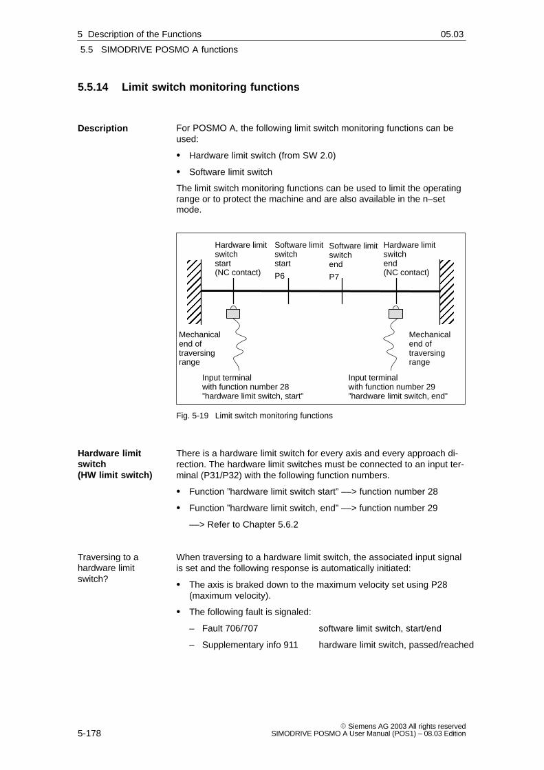
5
5.5 SIMODRIVE POSMO A functions
5-178� Siemens AG 2003 All rights reserved
SIMODRIVE POSMO A User Manual (POS1) – 08.03 Edition
5.5.14 Limit switch monitoring functions
For POSMO A, the following limit switch monitoring functions can beused:
� Hardware limit switch (from SW 2.0)
� Software limit switch
The limit switch monitoring functions can be used to limit the operatingrange or to protect the machine and are also available in the n–setmode.
ÏÏÏÏÏÏÏÏÏÏÏÏMechanical
end oftraversingrange
Mechanicalend oftraversingrange
Hardware limitswitchstart(NC contact)
Hardware limitswitchend(NC contact)
Software limitswitchstart
P6
Software limitswitchend
P7
Input terminalwith function number 28 ”hardware limit switch, start”
Input terminalwith function number 29 ”hardware limit switch, end”
ÏÏÏÏÏÏÏÏÏÏÏÏ
Fig. 5-19 Limit switch monitoring functions
There is a hardware limit switch for every axis and every approach di-rection. The hardware limit switches must be connected to an input ter-minal (P31/P32) with the following function numbers.
� Function ”hardware limit switch start” ––> function number 28
� Function ”hardware limit switch, end” ––> function number 29
––> Refer to Chapter 5.6.2
When traversing to a hardware limit switch, the associated input signalis set and the following response is automatically initiated:
� The axis is braked down to the maximum velocity set using P28(maximum velocity).
� The following fault is signaled:
– Fault 706/707 software limit switch, start/end
– Supplementary info 911 hardware limit switch, passed/reached
Description
Hardware limitswitch(HW limit switch)
Traversing to ahardware limitswitch?
5 Description of the Functions 02.9905.03

5
5.5 SIMODRIVE POSMO A functions
5-179� Siemens AG 2003 All rights reservedSIMODRIVE POSMO A User Manual (POS1) – 08.03 Edition
If an axis is located at a hardware limit switch, then it can be movedaway again as follows:
1. Acknowledge the fault
2. Return the axis to the valid traversing range
In the jog mode or via velocity, move away in a direction opposite tothe approach direction
or
1. Withdraw the controller enable (control signal ON/OFF1)
2. Set the input terminal (function number 28/29) to 0
Note
If the hardware limit switch was passed, then it is only possible tocontinue to traverse in the original direction, if after acknowledging thefault, the axis is traversed in the opposite direction and again passesover the hardware limit switch.
The software limit switch start (P6) and software limit switch end (P7)can be correspondingly set to limit the operating range or to protect themachine.
Notice
The software limit switches only become active if the followingconditions exist:
� P6 < P7
� pos mode: the axis is referenced (”reference point set” outputsignal)
Only then is it certain that the axis will be immediately stopped if itattempts to move out of the permissible range.
Note
The SW limit switch monitoring is dependent on the axis type asfollows:
For a linear axis or rotary axis with modulo correction, the following isvalid:
––> the software limit switches can be activated via P6<P7 and set via P6 and P7.
How can an axis bemoved away from ahardware switch?
Software-limit switch(SW limit switch)P6, P7
5 Description of the Functions02.9905.03

5
5.5 SIMODRIVE POSMO A functions
5-180� Siemens AG 2003 All rights reserved
SIMODRIVE POSMO A User Manual (POS1) – 08.03 Edition
When traversing to a software limit switch, the following response isautomatically initiated:
� When the axis reaches the software limit switch, then the axis isbraked down to the velocity set in P10 (maximum velocity). The axistherefore comes to a standstill after the limit switch.
� One of the following faults/warnings is signaled:
– Fault 706 software limit switch, start
– Fault 707 software limit switch, end
– Alarm 803 software limit switch, start
– Alarm 804 software limit switch, end
If an axis is located at a software limit switch, then it can be movedaway as follows:
1. Acknowledge the fault
2. Return the axis to the valid traversing range
In the jog mode or via velocity, move away in a direction opposite tothe approach direction
or
withdraw the controller enable (OFF1) and ”manually” move thedrive
Traversing to asoftware limitswitch?
How can an axis bemoved away from asoftware limitswitch?
5 Description of the Functions 02.9905.03

5
5.6 Parameters for SIMODRIVE POSMO A
5-181� Siemens AG 2003 All rights reservedSIMODRIVE POSMO A User Manual (POS1) – 08.03 Edition
5.6 Parameters for SIMODRIVE POSMO A
5.6.1 General information on parameters
The majority of the parameters required when commissioning thesystem for the first time are, for SIMODRIVE POSMO A, already pre-set in the factory (factory default).
All of the motor, power module and encoder data are known because ofthe fixed hardware. This means that the commissioning (start–up) datais limited to defining the gearbox (refer to Chapter 5.6.3) and thesystem geometry as well as some positioning data and software limitswitches.
There is a non–volatile memory to save parameters.
After parameters have been changed, they must be saved by transfer-ring them into the non–volatile memory.
The parameters are loaded from the non–volatile memory after powerup.
Transfer into the non–volatile memory?
� Set P971 from 0 to 1
� Data save is automatically acknowledged with P971 = 0
For safety reasons, several parameters can only be changed if a tra-versing block is not active, i.e. the motor is not moving (equalizationmovements initiated by the closed–loop position control are an excep-tion).
Exceptions:
� It is always possible to change parameters of traversing blockswhich are not selected.
� It is always possible to change parameters which do not have anappropriate ID.
Illegal change tasks are rejected in the PKW part with PROFIBUS faultnumber 17 (task not able to be executed due to the operating state)(refer to Chapter 5.1).
Generalinformation
Saving parameters
Changingparameters
5 Description of the Functions02.9904.01

5
5.6 Parameters for SIMODRIVE POSMO A
5-182� Siemens AG 2003 All rights reserved
SIMODRIVE POSMO A User Manual (POS1) – 08.03 Edition
The factory setting of parameters for SIMODRIVE POSMO A can bere–established if required.
Establish the factory default?
� Set P970 from 1 to 0
� Data load is automatically acknowledged with P970 = 1
The parameters are now in the volatile memory (RAM).
After the parameters have been transferred into the non–volatilememory, the factory default is loaded when powering up.
� Set P971 from 0 to 1
� Data save is automatically acknowledged with P971 = 0
For SIMODRIVE POSMO A, the following service functions are availa-ble with reference to parameters:
� P980:78 supported parameters
list of all supported parameters
� P990:78 changes with respect to the factory default
list of all of the parameters which have beenchanged with respect to modified parameters
The following parameters are available for positioning motor identifica-tion:
� P52 hardware version
� P53 firmware version
� P964:8 (from SW 1.4) drive identification
Setting the factorydefault
Service functionsfor theparameters(refer to Chapter5.6.2)
Parameters foridentification (referto Chapter 5.6.2)
5 Description of the Functions 02.9904.01

5
5.6 Parameters for SIMODRIVE POSMO A
5-183� Siemens AG 2003 All rights reservedSIMODRIVE POSMO A User Manual (POS1) – 08.03 Edition
5.6.2 List of parameters
Reader’s note
The parameters, listed in the following, are valid for all softwarereleases of SIMODRIVE POSMO A.
The complete list is updated corresponding to the Edition of thedocumentation (refer to the Edition status in the header line) andcorresponds to the software release of SIMODRIVE POSMO Adocumented here.
The parameters that are dependent on the software release areappropriately identified.
The parameters are shown in the parameter list as follows:
Pdddd || hh word_word word_word075W 300WMin Standard Max Units Data type Effectivexx xx xx xx yy zz
Parameter description
Parameter number (examples)P0010 Parameter 10 without indexP0082:28 Parameter 82 with index 0, 1, ... 27 (28 indices)P0082:13 Parameter 82 with index 13P0082:x Parameter 82 with undefined index xP0056.2 Parameter 56 bit 2
Parameter text
UnitsMSR: Measuring system grid1 MSR = 1 mm for P4 = 01 MSR = 1 degr. for P4 = 11 MSR = 1 inch for P4 = 2
decimal hexadecimal
Motor type
Specifies for which motor the parameter isvalid.075W ––> 75 W motor300W ––> 300 W motor
Effective� immediately ––> becomes immediately
effective when a change is made
When a parameter is changed, the motor mustalways be stationary. If a parameter can be changedwhile the axis is traversing, then an explicit referenceis made.
� RO ––> Read Only
The parameter can only be read and not written into.
Data type––> Refer to Chapter 4.3.1
Fig. 5-20 Parameter list
Explanation of theparameter list
5 Description of the Functions02.9904.01

5
5.6 Parameters for SIMODRIVE POSMO A
5-184� Siemens AG 2003 All rights reserved
SIMODRIVE POSMO A User Manual (POS1) – 08.03 Edition
The following parameters are available for SIMODRIVE POSMO A:
Version: 04.01.03
P0001 / 01 Axis type300WMin Standard Max Unit Data type Effective0 0 200000 MSR C4 immed.
0.0 ––> Linear axis> 0.0 ––> Rotary axisThe value corresponds to the modulo correction of the axis (e.g.: P1 = 360 ––> 0.0 – 359.9).Note:The following applies from SW 1.6:The parameter is limited in relation to the gear reduction factor and the travel per gear revolu-tion.The following formula applies: F = Conversion factor (mm ––> F = 1 ; inch ––> F = 25.4)P1 < 2147483647 * P2 / (F * 4096 * |P3| )The following applies from SW 2.0:Only the procedure with modulo axes is possible in the ”Speed setpoint” operating mode(P930).075WMin Standard Max Unit Data type Effective0 0 200000 MSR C4 immed.
0.0 ––> Linear axis> 0.0 ––> Rotary axisThe value corresponds to the modulo correction of the axis (e.g.: P1 = 360 ––> 0.0 – 359.9).Note:
The following applies from SW 1.6:The parameter is limited in relation to the gear reduction factor and the travel per gear revolu-tion.The following formula applies: F = Conversion factor (mm ––> F = 1 ; inch ––> F = 25.4)P1 < 2147483647 * P2 / (F * 816 * |P3| )The following applies from SW 2.0:Only the procedure with modulo axes is possible in the ”Speed setpoint” operating mode(P930).
Parameter list
5 Description of the Functions 02.9904.0108.03
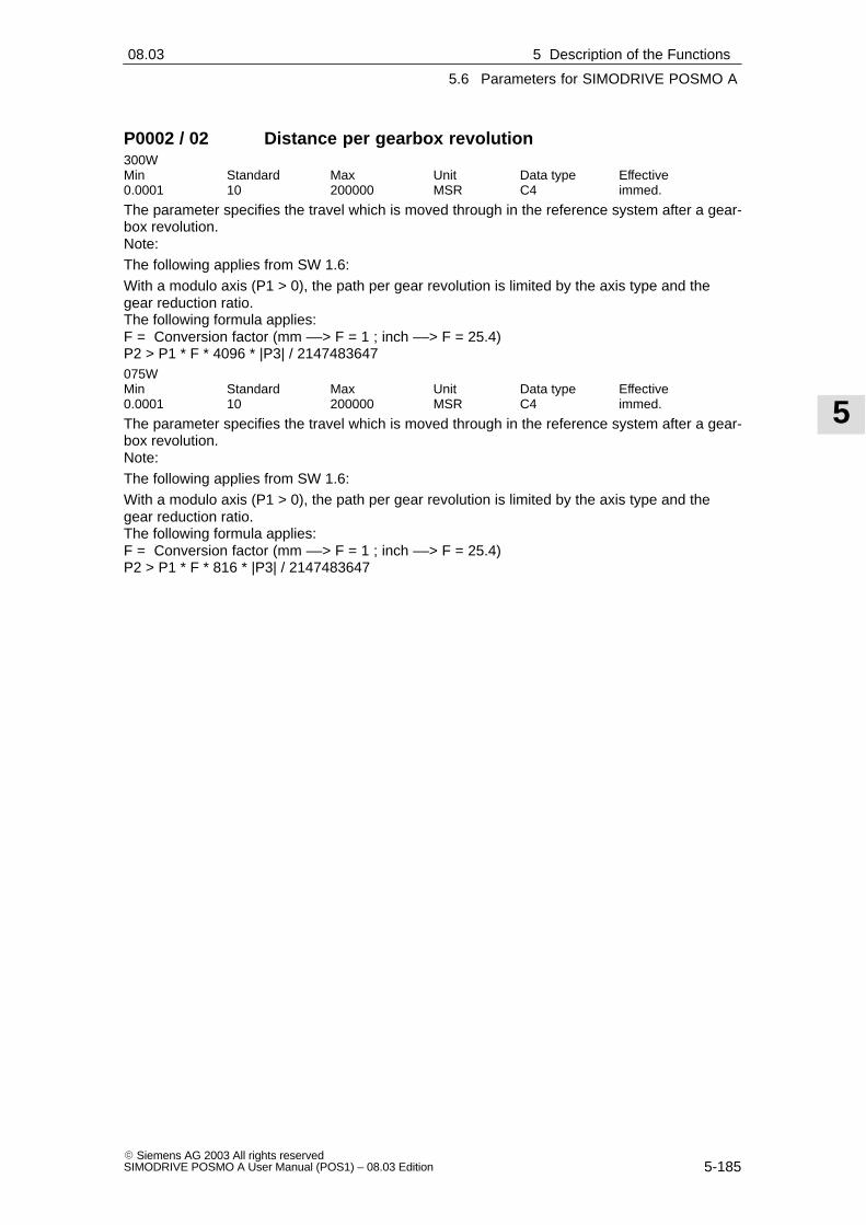
5
5.6 Parameters for SIMODRIVE POSMO A
5-185� Siemens AG 2003 All rights reservedSIMODRIVE POSMO A User Manual (POS1) – 08.03 Edition
P0002 / 02 Distance per gearbox revolution300WMin Standard Max Unit Data type Effective0.0001 10 200000 MSR C4 immed.
The parameter specifies the travel which is moved through in the reference system after a gear-box revolution.Note:The following applies from SW 1.6:With a modulo axis (P1 > 0), the path per gear revolution is limited by the axis type and thegear reduction ratio.The following formula applies: F = Conversion factor (mm ––> F = 1 ; inch ––> F = 25.4)P2 > P1 * F * 4096 * |P3| / 2147483647075WMin Standard Max Unit Data type Effective0.0001 10 200000 MSR C4 immed.
The parameter specifies the travel which is moved through in the reference system after a gear-box revolution.Note:The following applies from SW 1.6:With a modulo axis (P1 > 0), the path per gear revolution is limited by the axis type and thegear reduction ratio.The following formula applies: F = Conversion factor (mm ––> F = 1 ; inch ––> F = 25.4)P2 > P1 * F * 816 * |P3| / 2147483647
5 Description of the Functions02.9904.0108.03

5
5.6 Parameters for SIMODRIVE POSMO A
5-186� Siemens AG 2003 All rights reserved
SIMODRIVE POSMO A User Manual (POS1) – 08.03 Edition
P0003 / 03 Gearbox step-down ratio300WMin Standard Max Unit Data type Effective–200000 1 200000 – C4 immed.
The step-down ratio should be entered in accordance with the gear used.Note:P3 = 0 is not permissible.Sign change ––> direction of rotation changeThis parameter has a gearbox-dependent factory default.The following applies before SW 1.3: Min. value = 0.0001The following applies from SW 1.6:
With a modulo axis (P1 > 0), the gear reduction ratio is limited by the path per gear revolutionand the axis type.The following formula applies: F = Conversion factor (mm –> F = 1 ; inch –> F = 25.4)|P3| < 2147483647 * P2 / (F * 4096 * P1)075WMin Standard Max Unit Data type Effective–200000 1 200000 – C4 immed.
The step-down ratio should be entered in accordance with the gear used.Note:P3 = 0 is not permissible.Sign change ––> direction of rotation changeThis parameter has a gearbox-dependent factory default.The following applies before SW 1.3: Min. value = 0.0001
The following applies from SW 1.6:With a modulo axis (P1 > 0), the gear reduction ratio is limited by the path per gear revolutionand the axis type.The following formula applies: F = Conversion factor (mm –> F = 1 ; inch –> F = 25.4)|P3| < 2147483647 * P2 / (F * 816 * P1)
P0004 / 04 Dimension units300W 075WMin Standard Max Unit Data type Effective0 0 2 – I2 immed.
Dimension units for parameter values (0 = mm, 1 = degree, 2 = inch).
P0005 / 05 Reference point coordinate300W 075WMin Standard Max Unit Data type Effective–200000 0 200000 MSR C4 immed.
The parameter specifies the position at the reference point.Note:The parameter value can be changed while traversing.
5 Description of the Functions 02.9904.0108.03

5
5.6 Parameters for SIMODRIVE POSMO A
5-187� Siemens AG 2003 All rights reservedSIMODRIVE POSMO A User Manual (POS1) – 08.03 Edition
P0006 / 06 Software limit switch, start300W 075WMin Standard Max Unit Data type Effective–200000 –200000 200000 MSR C4 immed.
The parameter specifies the software limit switch, left negative.de-activated: P6 = P7activated: P6 < P7Note:Also refer to P7.The following applies from SW 2.0:Software limit switches are not possible in the ”Speed setpoint” operating mode (P930).
P0007 / 07 Software limit switch, end300W 075WMin Standard Max Unit Data type Effective–200000 200000 200000 MSR C4 immed.
The parameter specifies the software limit switch, right positive.de-activated: P6 = P7activated: P6 < P7Note:Also refer to P6.The following applies from SW 2.0:Software limit switches are not possible in the ”Speed setpoint” operating mode (P930).
P0008 / 08 Maximum speed300WMin Standard Max Unit Data type Effective0 3000 3800 rpm C4 immed.
Max. motor speed referred to the motor axis075WMin Standard Max Unit Data type Effective0 3000 3600 rpm C4 immed.
Max. motor speed referred to the motor axis.
P0009 / 09 Acceleration time300W 075WMin Standard Max Unit Data type Effective10 100 15000 ms T2 immed.
During this time, in the speed-controlled operation, the setpoint is set as follows:Ramp-up: From zero up to the maximum permissible actual speedRamp-down: From the maximum permissible actual value down to zeroThe following applies from SW 2.0:The ramp-up time can be changed with immediate effect in the ”Speed setpoint” operating mode.This is also possible when the drive is moving.
P0010 / 0A Maximum motor velocity300W 075WMin Standard Max Unit Data type Effective0 30000 2000000 MSR/min I4 immed.
Max. permissible velocity, dependent on the system.The max. speed in P8 was not exceeded in operation.Note:This parameter has a gearbox-dependent factory default.
5 Description of the Functions02.9904.0108.03

5
5.6 Parameters for SIMODRIVE POSMO A
5-188� Siemens AG 2003 All rights reserved
SIMODRIVE POSMO A User Manual (POS1) – 08.03 Edition
P0011 / 0B Target range300W 075WMin Standard Max Unit Data type Effective0 2 200000 MSR C4 immed.
The parameter specifies the precise stopping range (precise stopping window).Note:P0011 may not be set too low, as otherwise a traversing task cannot be completed. The settingis dependent on the encoder resolution and the gear ratio.
P0012 / 0C Max. following error300W 075WMin Standard Max Unit Data type Effective0 200000 200000 MSR C4 immed.
The parameter specifies the maximum permissible following error.Note:The following error status is displayed using status signal ZSW.8 (no following error / followingerror).
P0013 / 0D Monitoring time300W 075WMin Standard Max Unit Data type Effective0 100 2000000 ms T4 immed.
After the motion block has been completed (position ref. value = target ref. value), this time isstarted.After the time has expired, the standstill monitoring and P gain are activated for standstill (P54,P57).
P0014 / 0E Standstil range300W 075WMin Standard Max Unit Data type Effective0 200000 200000 MSR C4 immed.
Tolerance range for the closed-loop position control at standstill.Note:The parameter value can be changed while traversing.
P0015 / 0F Backlash compensation300W 075WMin Standard Max Unit Data type Effective–200000 0 200000 MSR C4 immed.
The mechanical backlash for direction reversal can be compensated using this parameter.P15 = negative ––> Correction direction negativeP15 = positive ––> Correction direction positiveNote:The following applies before SW 1.4: Min. value = 0.0
5 Description of the Functions 02.9904.0108.03

5
5.6 Parameters for SIMODRIVE POSMO A
5-189� Siemens AG 2003 All rights reservedSIMODRIVE POSMO A User Manual (POS1) – 08.03 Edition
P0016 / 10 Max. overcurrent300WMin Standard Max Unit Data type Effective0 10.5 42 A C4 immed.
Max. overcurrent for the breakaway torque.Note:This parameter has a gearbox-dependent factory default.The parameter is valid for: n < 100 RPM and max. 500 msThe parameter value can be changed while traversing.075WMin Standard Max Unit Data type Effective0 9 18 A C4 immed.
Max. overcurrent for the breakaway torque.Note:This parameter has a gearbox-dependent factory default.The parameter is valid for: n < 100 RPM and max. 500 msThe following applies as from SW 1.5:The parameter value can be changed while traversing.
P0017 / 11 P gain, speed controller300WMin Standard Max Unit Data type Effective0 3 100 – I4 immed.
The parameter specifies the P gain for traversing operation.Note:The parameter value can be changed while traversing.Also refer to P54075WMin Standard Max Unit Data type Effective0 20 100 – I4 immed.
The parameter specifies the P gain for traversing operation.Note:The parameter value can be changed while traversing.The following applies before SW 1.2: Max. value = 40Also refer to P54
P0018 / 12 Integral action time, speed controller300WMin Standard Max Unit Data type Effective2 10 1000 ms T2 immed.
The parameter specifies the I component for the speed controller.Note:The parameter value can be changed while traversing.075WMin Standard Max Unit Data type Effective2 22 1000 ms T2 immed.
The parameter specifies the I component for the speed controller.Note:The parameter value can be changed while traversing.
5 Description of the Functions02.9904.0108.03

5
5.6 Parameters for SIMODRIVE POSMO A
5-190� Siemens AG 2003 All rights reserved
SIMODRIVE POSMO A User Manual (POS1) – 08.03 Edition
P0019 / 13 Kv factor (position loop gain)300W 075WMin Standard Max Unit Data type Effective0.1 1 9.9 1000/min C4 immed.
The parameter defines at which traversing velocity of the axis, which following error is obtained.Kv factor significanceLow: Slow response to a setpoint-actual value difference, following error is highHigh: Fast response to a setpoint-actual value difference, following error is low
P0020 / 14 Current setpoint smoothing300W 075WMin Standard Max Unit Data type Effective0.3 0.3 10 ms C4 immed.
Lowpass (PT1 characteristics)Note:The parameter value can be changed while traversing.
P0021 / 15 Speed setpoint smoothing300W 075WMin Standard Max Unit Data type Effective2 2 100 ms C4 immed.
Lowpass (PT1 characteristics)Note:The parameter value can be changed while traversing.
P0022 / 16 Maximum acceleration300WMin Standard Max Unit Data type Effective0 4000 200000 MSR/s2 C4 immed.
Max. acceleration for closed-loop position controlled operation.Note:This parameter has a gearbox-dependent factory default.075WMin Standard Max Unit Data type Effective0 1000 200000 MSR/s2 C4 immed.
Max. acceleration for closed-loop position controlled operation.Note:This parameter has a gearbox-dependent factory default.
P0023 / 17 Jerk time constant300W 075WMin Standard Max Unit Data type Effective0 0 400 ms T4 immed.
The acceleration/deceleration is changed over this time.Note:Input resolution = 10 ms
5 Description of the Functions 02.9904.0108.03

5
5.6 Parameters for SIMODRIVE POSMO A
5-191� Siemens AG 2003 All rights reservedSIMODRIVE POSMO A User Manual (POS1) – 08.03 Edition
P0024 / 18 Override velocity300W 075WMin Standard Max Unit Data type Effective0 16384 16384 % N2 immed.
Closed-loop speed control: referred to P8 (maximum speed)Closed-loop position controlled: referred to P10 (maximum velocity)Note:The parameter value can be changed while traversing.
P0025 / 19 Override acceleration300W 075WMin Standard Max Unit Data type Effective0 16384 16384 % N2 immed.
Closed-loop speed control: referred to P9 (acceleration time)P25 = 50% means: Doubling of ramp-up timeP25 = 10% means: Multiplication by 10 of ramp-up time
Closed-loop position controlled: referred to P22 (maximum acceleration)
The following applies from SW 2.0:The acceleration override can be changed with immediate effect in the ”Speed setpoint” opera-ting mode.This is also possible when the drive is moving.
P0026 / 1A Override speed, jogging300W 075WMin Standard Max Unit Data type Effective0 3276 16384 % N2 immed.
Referred to P8 (maximum speed).Is calculated in addition to P24 (override velocity).Note:The parameter value can be changed while traversing.
P0027 / 1B Override acceleration, jogging300W 075WMin Standard Max Unit Data type Effective0 8192 16384 % N2 immed.
Refer to P9 (acceleration time).Is calculated in addition to P25 (override acceleration).
P0028 / 1C Max. current300WMin Standard Max Unit Data type Effective0 10.5 21 A C4 immed.
Upper limit, motor current.Note:The parameter value can be changed while traversing.This parameter has a gearbox-dependent factory default.075WMin Standard Max Unit Data type Effective0 9 9 A C4 immed.
Upper limit, motor current.Note:The parameter value can be changed while traversing.This parameter has a gearbox-dependent factory default.
5 Description of the Functions02.9904.0108.03

5
5.6 Parameters for SIMODRIVE POSMO A
5-192� Siemens AG 2003 All rights reserved
SIMODRIVE POSMO A User Manual (POS1) – 08.03 Edition
P0029 / 1D Electronics temperature tolerance time300W 075WMin Standard Max Unit Data type Effective0 120000 2000000 ms T4 immed.
For an electronics overtemperature condition, after this time, the warning is changed to a fault,i.e. the appropriate response is activated.Note:The electronics temperature is displayed using P47.Input resolution = 10 msThe parameter value can be changed while traversing.
P0030 / 1E Fault suppression300W 075WMin Standard Max Unit Data type Effective0 0 F Hex I2 immed.
If the bit is set, instead of the appropriate fault, only a warning is output.Bit 0: Speed controller at its endstopBit 1: Start, software limit switch or end, software limit switch Software limit switches always stop an axis.Bit 2: Standstill monitoringBit 3: Undervoltage of the load current supply (from SW 1.6) Note:The parameter value can be changed while traversing.
P0031 / 1F Function terminal 1300W 075WMin Standard Max Unit Data type Effective0 0 479 – I2 immed.
The function of the terminal is defined using this parameter:
The following applies from SW 2.0:The meaning of terminal parameterization depends on the operating mode (P930).Parameters with different meanings are marked.Parameters which are not marked have the same function in both operating modes.0 No function1 I (STW.4) Positioning operating mode: Operating condition positioning. Stop and reject
the actual traversing task on cancelation. StopSpeed setpoint operating mode: Ramp-function generator enable. Stop with maximum acceleration on cancelation.
2 I (STW.5) Positioning operating mode: Operating condition positioning. Stop without rejecting the actual traversing task on cancelation. StopSpeed setpoint operating mode: Ramp-function generator START / Ramp-function generator STOP. The actual speed remains constant on cancelation.
3 I (STW.6) Positioning operating mode: Activate traversing task Speed setpoint operating mode: Setpoint enable. Deceleration at the ramp oncancelation.
4 I (STW.8) Positioning operating mode: Jogging –Speed setpoint operating mode: No function
5 I (STW.9) Positioning operating mode: Jogging +Speed setpoint operating mode: No function
6 I (STW.11) Positioning operating mode: ReferencingSpeed setpoint operating mode: No function
7 I (STW.12) Positioning operating mode: Automatic single block.Speed setpoint operating mode: No function
5 Description of the Functions 02.9904.0108.03
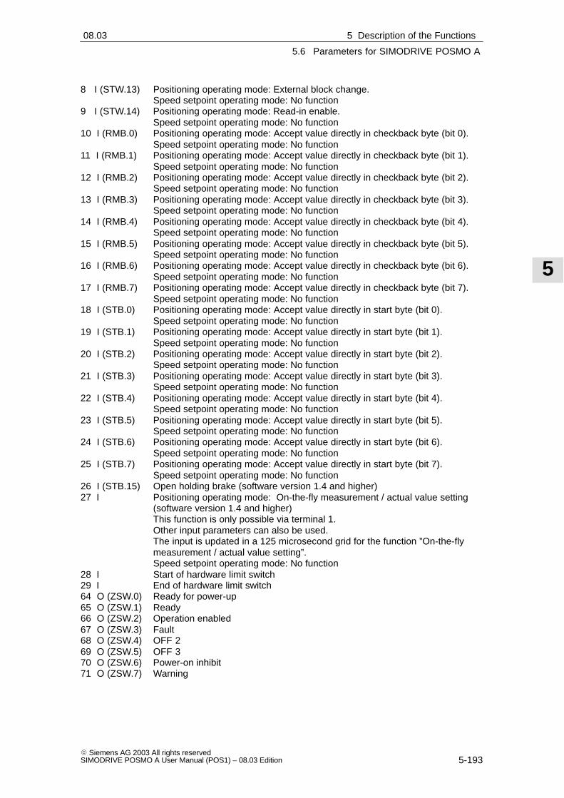
5
5.6 Parameters for SIMODRIVE POSMO A
5-193� Siemens AG 2003 All rights reservedSIMODRIVE POSMO A User Manual (POS1) – 08.03 Edition
8 I (STW.13) Positioning operating mode: External block change.Speed setpoint operating mode: No function
9 I (STW.14) Positioning operating mode: Read-in enable.Speed setpoint operating mode: No function
10 I (RMB.0) Positioning operating mode: Accept value directly in checkback byte (bit 0).Speed setpoint operating mode: No function
11 I (RMB.1) Positioning operating mode: Accept value directly in checkback byte (bit 1).Speed setpoint operating mode: No function
12 I (RMB.2) Positioning operating mode: Accept value directly in checkback byte (bit 2).Speed setpoint operating mode: No function
13 I (RMB.3) Positioning operating mode: Accept value directly in checkback byte (bit 3).Speed setpoint operating mode: No function
14 I (RMB.4) Positioning operating mode: Accept value directly in checkback byte (bit 4).Speed setpoint operating mode: No function
15 I (RMB.5) Positioning operating mode: Accept value directly in checkback byte (bit 5).Speed setpoint operating mode: No function
16 I (RMB.6) Positioning operating mode: Accept value directly in checkback byte (bit 6).Speed setpoint operating mode: No function
17 I (RMB.7) Positioning operating mode: Accept value directly in checkback byte (bit 7).Speed setpoint operating mode: No function
18 I (STB.0) Positioning operating mode: Accept value directly in start byte (bit 0).Speed setpoint operating mode: No function
19 I (STB.1) Positioning operating mode: Accept value directly in start byte (bit 1).Speed setpoint operating mode: No function
20 I (STB.2) Positioning operating mode: Accept value directly in start byte (bit 2).Speed setpoint operating mode: No function
21 I (STB.3) Positioning operating mode: Accept value directly in start byte (bit 3).Speed setpoint operating mode: No function
22 I (STB.4) Positioning operating mode: Accept value directly in start byte (bit 4).Speed setpoint operating mode: No function
23 I (STB.5) Positioning operating mode: Accept value directly in start byte (bit 5).Speed setpoint operating mode: No function
24 I (STB.6) Positioning operating mode: Accept value directly in start byte (bit 6).Speed setpoint operating mode: No function
25 I (STB.7) Positioning operating mode: Accept value directly in start byte (bit 7).Speed setpoint operating mode: No function
26 I (STB.15) Open holding brake (software version 1.4 and higher)27 I Positioning operating mode: On-the-fly measurement / actual value setting
(software version 1.4 and higher)This function is only possible via terminal 1.Other input parameters can also be used.The input is updated in a 125 microsecond grid for the function ”On-the-fly measurement / actual value setting”.Speed setpoint operating mode: No function
28 I Start of hardware limit switch29 I End of hardware limit switch64 O (ZSW.0) Ready for power-up65 O (ZSW.1) Ready66 O (ZSW.2) Operation enabled67 O (ZSW.3) Fault68 O (ZSW.4) OFF 269 O (ZSW.5) OFF 370 O (ZSW.6) Power-on inhibit71 O (ZSW.7) Warning
5 Description of the Functions02.9904.0108.03

5
5.6 Parameters for SIMODRIVE POSMO A
5-194� Siemens AG 2003 All rights reserved
SIMODRIVE POSMO A User Manual (POS1) – 08.03 Edition
72 O (ZSW.8) Positioning operating mode: Following error.Speed setpoint operating mode: Speed within tolerance band
73 O (ZSW.10) Positioning operating mode: Setpoint position reached.Speed setpoint operating mode: Ramp-up complete
74 O (ZSW.11) Positioning operating mode: Reference point set.Speed setpoint operating mode: Checkback from Terminal1
75 O (ZSW.12) Positioning operating mode: Acknowledge traversing task.Speed setpoint operating mode: Checkback from Terminal2
76 O (ZSW.13) Drive moves77 O (ZSW.14) Positioning operating mode: Within traversing block.
Speed setpoint operating mode: No function78 O (ZSW.15) Load power supply available79 O (STB.0) Positioning operating mode: Accept value directly from start byte (bit 0).
Speed setpoint operating mode: No function80 O (STB.1) Positioning operating mode: Accept value directly from start byte (bit 1).
Speed setpoint operating mode: No function81 O (STB.2) Positioning operating mode: Accept value directly from start byte (bit 2).
Speed setpoint operating mode: No function82 O (STB.3) Positioning operating mode: Accept value directly from start byte (bit 3).
Speed setpoint operating mode: No function83 O (STB.4) Positioning operating mode: Accept value directly from start byte (bit 4).
Speed setpoint operating mode: No function84 O (STB.5) Positioning operating mode: Accept value directly from start byte (bit 5).
Speed setpoint operating mode: No function85 O (STB.6) Positioning operating mode: Accept value directly from start byte (bit 6).
Speed setpoint operating mode: No function86 O (STB.7) Positioning operating mode: Accept value directly from start byte (bit 7).
Speed setpoint operating mode: No function87 O (RMB.0) Positioning operating mode: Accept value directly from checkback byte (bit 0)
(software version 1.2 and higher).Speed setpoint operating mode: No function
88 O (RMB.1) Positioning operating mode: Accept value directly from checkback byte (bit 1) (software version 1.2 and higher).Speed setpoint operating mode: No function
89 O (RMB.2) Positioning operating mode: Accept value directly from checkback byte (bit 2) (software version 1.2 and higher).Speed setpoint operating mode: No function
90 O (RMB.3) Positioning operating mode: Accept value directly from checkback byte (bit 3) (software version 1.2 and higher).Speed setpoint operating mode: No function
91 O (RMB.4) Positioning operating mode: Accept value directly from checkback byte (bit 4) (software version 1.2 and higher).Speed setpoint operating mode: No function
92 O (RMB.5) Positioning operating mode: Accept value directly from checkback byte (bit 5) (software version 1.2 and higher).Speed setpoint operating mode: No function
93 O (RMB.6) Positioning operating mode: Accept value directly from checkback byte (bit 6) (software version 1.2 and higher).Speed setpoint operating mode: No function
94 O (RMB.7) Positioning operating mode: Accept value directly from checkback byte (bit 7) (software version 1.2 and higher).Speed setpoint operating mode: No function
95 O Control external holding brake (software version 1.4 and higher)100 I (STW.0) OFF 1 logically ANDed with the terminal
5 Description of the Functions 02.9904.0108.03

5
5.6 Parameters for SIMODRIVE POSMO A
5-195� Siemens AG 2003 All rights reservedSIMODRIVE POSMO A User Manual (POS1) – 08.03 Edition
101 I (STW.1) OFF 2 logically ANDed with the terminal102 I (STW.2) OFF 3 logically ANDed with the terminalNote:If a terminal is parameterized as input or output, the following applies: ––> Addition with 256 means:
Positioning operating mode: Status display via RMB.6/7. (terminal 1/2) (SW 1.4 and higher).Speed setpoint operating mode: Status check back via ZSW.11 (terminal 1) ZSW.12 (terminal 2).
If a terminal is parameterized as output, the following applies:––> Addition with 128 means:
Inversion for signal output.The parameter value can be changed while traversing.
P0032 / 20 Function terminal 2300W 075WMin Standard Max Unit Data type Effective0 0 479 – I2 immed.
Refer to P31 (function, terminal 1).
P0033 / 21 Address, test socket 1300W 075WMin Standard Max Unit Data type Effective0 FC32 FFFFFFFF Hex I4 immed.
The parameter addresses the measured value for output via the analog test output.FC00 Speed setpoint (motor shaft)FC66 Actual speed value (motor shaft)FC6A Position actual valueFC32 Current actual valueFC38 I set (speed controller)FC3A I set (smoothed)Note:The parameter value can be changed while traversing.
P0034 / 22 Shift factor, test socket 1300W 075WMin Standard Max Unit Data type Effective0 7 F Hex I2 immed.
Shift factor for analog test socket 1.Note:Shift factor change of +1 corresponds to doubling the valueShift factor change by –1 corresponds to halving the valueThe parameter value can be changed while traversing.
P0035 / 23 Offset, test socket 1300W 075WMin Standard Max Unit Data type Effective0 80 FF Hex I2 immed.
Offset for analog test socket 1.Note:With offset = 80 hex, for ”0” 2.5 V is output.The parameter value can be changed while traversing.
5 Description of the Functions02.9904.0108.03

5
5.6 Parameters for SIMODRIVE POSMO A
5-196� Siemens AG 2003 All rights reserved
SIMODRIVE POSMO A User Manual (POS1) – 08.03 Edition
P0036 / 24 Address, test socket 2300W 075WMin Standard Max Unit Data type Effective0 FC66 FFFFFFFF Hex I4 immed.
Note:Refer to P33 (address, test socket 1).
P0037 / 25 Shift factor, test socket 2300W 075WMin Standard Max Unit Data type Effective0 0 F Hex I2 immed.
Note:Refer to P34 (shift factor, test socket 1).
P0038 / 26 Offset, test socket 2300W 075WMin Standard Max Unit Data type Effective0 80 FF Hex I2 immed.
Note:Refer to P35 (offset, test socket 1).
P0039 / 27 Position setpoint300W 075WMin Standard Max Unit Data type Effective– – – MSR C4 RO
This parameter specifies the position setpoint in the selected unit of measurement.
P0040 / 28 Position actual value300W 075WMin Standard Max Unit Data type Effective–200000 0 200000 MSR C4 immed.
This position is directly accepted as new actual value by writing the required position into P40The drive must be closed-loop controlled and stationary.The axis is then considered to have been referenced.The following applies from SW 2.0:It is possible to write the actual position value in the ”Speed setpoint” operating mode.The axis is always dereferenced in this operating mode.
P0041 / 29 Speed setpoint300W 075WMin Standard Max Unit Data type Effective– – – rpm C4 RO
”Positioning” operating mode: Indicates the speed setpoint relative to the motor shaft.
P0042 / 2A Actual speed300W 075WMin Standard Max Unit Data type Effective– – – rpm C4 RO
”Positioning” operating mode: Indicates the speed setpoint relative to the motor shaft.
5 Description of the Functions 02.9904.0108.03

5
5.6 Parameters for SIMODRIVE POSMO A
5-197� Siemens AG 2003 All rights reservedSIMODRIVE POSMO A User Manual (POS1) – 08.03 Edition
P0043 / 2B Current setpoint300W 075WMin Standard Max Unit Data type Effective– – – A C4 RO
P0044 / 2C Current actual value300W 075WMin Standard Max Unit Data type Effective– – – A C4 RO
P0045 / 2D Timer status300W 075WMin Standard Max Unit Data type Effective– – – ms T4 RO
P0046 / 2E Following error300W 075WMin Standard Max Unit Data type Effective– – – MSR C4 RO
P0047 / 2F Electronics temperature300W 075WMin Standard Max Unit Data type Effective– – – �C C4 RO
P0048 / 30 Actual traversing block, block number300W 075WMin Standard Max Unit Data type Effective– – – – I2 RO
The parameter specifies the block number of the traversing block presently being processed.
P0049 / 31 Following block, block number300W 075WMin Standard Max Unit Data type Effective– – – – I2 RO
The parameter specifies the block number of the next block.The following block is the next traversing block to be executed.
P0050 / 32 Velocity setpoint300W 075WMin Standard Max Unit Data type Effective– – – MSR/min I4 RO
P0051 / 33 Actual velocity300W 075WMin Standard Max Unit Data type Effective– – – MSR/min I4 RO
P0052 / 34 Hardware version300W 075WMin Standard Max Unit Data type Effective– – – – I4 RO
The parameter indicates the hardware version of the motor.= 1 ––> Hardware version A= 4 ––> Hardware version D, etc.
5 Description of the Functions02.9904.0108.03

5
5.6 Parameters for SIMODRIVE POSMO A
5-198� Siemens AG 2003 All rights reserved
SIMODRIVE POSMO A User Manual (POS1) – 08.03 Edition
P0053 / 35 Firmware version300W 075WMin Standard Max Unit Data type Effective– – – – I4 RO
The parameter indicates the firmware version of the drive.Example:= 10202 ––> Firmware version 01.02.02
P0054 / 36 P gain, speed controller standstill300WMin Standard Max Unit Data type Effective1 2 100 – I4 immed.
This parameter specifies the P gain for axis at standstill.Note:Refer to P56.2The parameter value can be changed while traversing.075WMin Standard Max Unit Data type Effective1 5 100 – I4 immed.
This parameter specifies the P gain for axis at standstill.Note:The following applies before SW 1.2: Max. value = 40The following applies before SW 1.4: Min. value = 0Refer to P56.2The parameter value can be changed while traversing.
P0055 / 37 Signal position300W 075WMin Standard Max Unit Data type Effective– – – MSR C4 RO
Last position for external block change or when canceling the program block by withdrawing thestart byte condition.Note:The following is valid for the position for rotary axis:The following applies before SW 1.3: ––> no modulo evaluationThe following applies from SW 1.3: ––> modulo evaluation
5 Description of the Functions 02.9904.0108.03

5
5.6 Parameters for SIMODRIVE POSMO A
5-199� Siemens AG 2003 All rights reservedSIMODRIVE POSMO A User Manual (POS1) – 08.03 Edition
P0056 / 38 Operating options300W 075WMin Standard Max Unit Data type Effective0 0 FFFF Hex V2 immed.
Bit 1.0 Drive referenced and behavior after restart (from SW 1.2)= 00: The motor is referenced when powering-up again, if it was already referenced
when powered-down and is stationary. The behavior is the same as before SW 1.2.
= 01: The motor is referenced when powering-up again if it was already referenced when powered-down and was not stationary (ZSW.13).
= 1x: The motor is not referenced when powering-up again.(x: the bit can either 0 or 1)
The following applies from SW 2.0:The drive is always dereferenced in the ”Speed setpoint” operating mode (P930). Bit 0 and bit 1 have no function in this operating mode.
Bit 2 P gain at standstill (from SW 1.3)= 0: Holding controller P gain active (P57)= 1: Speed controller P gain active (P54)The following applies from SW 2.0:The speed controller is always active in the ”Speed setpoint” operating mode (P930).Bit 2 has no meaning here.P54 is effective at zero speed.
Bit 3 Response of Bit 10 in the status word ”Setpoint position reached” (as of SW 1.6)= 0: ”Setpoint position reached” is signalled when:
– traversing block fully completed – Abort of the traversing block by: Fault, Stop or OFF commands
= 1: ”Setp. pos. reached” is signalled only after full completion of the traversing block.Bit 4 Open holding brake (from SW 1.4)
= 0: Brake sequence control effective= 1: Open holding brake
Bit 5 Monitoring, holding brake undervoltage (from SW 1.4)= 0: De-activated (P947.12)= 1: Activated (P947.12)
Bit 6 Open holding brake is also effective for external holding brakes (from SW 1.4)= 0: Brake sequence control effective= 1: Open holding brake is also effective for an external holding brake
P0057 / 39 P gain, holding controller standstill300WMin Standard Max Unit Data type Effective5 20 250 – I4 immed.
P gain for axis standstill.Note:Refer to P56.2075WMin Standard Max Unit Data type Effective50 100 250 – I4 immed.
P gain for axis standstill.Note:Refer to P56.2Available from SW 1.3.
5 Description of the Functions02.9904.0108.03

5
5.6 Parameters for SIMODRIVE POSMO A
5-200� Siemens AG 2003 All rights reserved
SIMODRIVE POSMO A User Manual (POS1) – 08.03 Edition
P0058 / 3A Holding brake, brake opening time300W 075WMin Standard Max Unit Data type Effective0 100 1000 ms T4 immed.
For ”pulse enable” the setpoint is output delayed by this time.Note:Available from SW 1.4.
P0059 / 3B Speed, close holding brake300W 075WMin Standard Max Unit Data type Effective0 10 3000 rpm C4 immed.
When withdrawing ”controller enable” and this speed is fallen below, the holding brake is closed.The holding brake is always closed after the time in P60 has expired.Note:Available from SW 1.4.
P0060 / 3C Holding brake, brake delay time300W 075WMin Standard Max Unit Data type Effective0 400 10000 ms T4 immed.
When withdrawing ”controller enable” this time is started and after it expires, the holding brakeis closed.The holding brake can also be closed if the speed in P59 is fallen below.Note:Available from SW 1.4.
P0061 / 3D Holding brake, control blocking time300W 075WMin Standard Max Unit Data type Effective0 100 1000 ms T4 immed.
When withdrawing the brake control signals, this time is started and after it has expired, the pul-ses are deleted.Note:Available from SW 1.4.
P0062 / 3E Measuring position300W 075WMin Standard Max Unit Data type Effective– – – MSR C4 RO
The position value for the ”flying measurement” function is written into this parameter.Note:This parameter is overwritten at each measuring operation.Available from SW 1.4.
5 Description of the Functions 02.9904.0108.03

5
5.6 Parameters for SIMODRIVE POSMO A
5-201� Siemens AG 2003 All rights reservedSIMODRIVE POSMO A User Manual (POS1) – 08.03 Edition
P0080:28 / 50 Program control word PSW300W 075WMin Standard Max Unit Data type Effective0 3 FFFF Hex V2 immed.
The program control word defines the general behavior of a traversing block.Bit 0 Motion type
= 1: Enter position and velocity= 0: Enter speed
Bit 1 Positioning type (only when positioning)= 1: Relative= 0: Absolute
Bit 2 Timer type= 1: Traverse as long as the timer no longer runs= 0: Traverse as long as the timer runs
Bit 3 Logic operation between timer with start byte= 1: Traverse if the timer or start bytes are fulfilled= 0: Traverse if the timer and start byte are fulfilled
Bit 4 Return jump to program= 1: Jump to the start of the program after the end of the block= 0: No response
Bit 5 Traversing type= 1: Continuous path mode= 0: Precise stop
Bit 6 Negate start byte condition= 1: Block is executed if at least one of the bits set in the start mask is not configured= 0: Normal evaluation
Bit 7 SMStart type (from SW 1.2)= 1: The following is valid dependent on the condition defined in SMStart:
Fulfilled ––> Execute block, Not fulfilled ––> Skip block= 0: Wait until the start condition is fulfilled acc. to SMStart
Bit 8 Program stop (from SW 1.2)= 1: End of program at end of block= 0: No response
Bit 9 Set reference position, actual position= 1: Active
Before SW 1.4 the following applies: At the end of the block the actual position is set the same as the signaled position.The following applies from SW 1.4: At the end of the block, the position of the lastzero mark is set the same as the signaled position and the drive is referenced.
= 0: InactiveBit 10 Flying actual value setting (from SW 1.4)
= 1: Active= 0: Inactive
Bit 11 Flying measurement (from SW 1.4)= 1: Active= 0: Inactive
Bit 12 Traverse through the shorted path (from SW 1.4) = 1: Active (only for modulo correction with absolute position data)= 0: Inactive
Note:Refer to P81:28 (target position).
5 Description of the Functions02.9904.0108.03

5
5.6 Parameters for SIMODRIVE POSMO A
5-202� Siemens AG 2003 All rights reserved
SIMODRIVE POSMO A User Manual (POS1) – 08.03 Edition
P0081:28 / 51 Target position300W 075WMin Standard Max Unit Data type Effective–200000 0 200000 MSR C4 immed.
The parameter specifies the target position in the traversing block.Note:Index (using as an example P81):P81:0 ––> no significanceP81:1 ––> traversing block 1P81:2 ––> traversing block 2...P81:27 ––> traversing block 27Block numbers (factory default):1 Traversing block jogging –2 Traversing block jogging +3 ... 12 Single block13 ... 17 Program 118 ... 22 Program 223 ... 27 Program 3All blocks before program 1 are single blocks.
P0082:28 / 52 Velocity or speed300W 075WMin Standard Max Unit Data type Effective–16384 16384 16384 % N2 immed.
The parameter specifies the velocity or speed in the traversing block.Note:Refer to P81:28 (target position).
P0083:28 / 53 Acceleration300W 075WMin Standard Max Unit Data type Effective0 16384 16384 % N2 immed.
The parameter specifies the acceleration in the traversing block.Note:Refer to P81:28 (target position).
P0084:28 / 54 Timer value300W 075WMin Standard Max Unit Data type Effective0 0 20000000 ms T4 immed.
Contains the time required for the timer.Note:Value 0 de-activates the function.Input resolution = 10 msRefer to P81:28 (target position).
5 Description of the Functions 02.9904.0108.03

5
5.6 Parameters for SIMODRIVE POSMO A
5-203� Siemens AG 2003 All rights reservedSIMODRIVE POSMO A User Manual (POS1) – 08.03 Edition
P0085:28 / 55 Message position300W 075WMin Standard Max Unit Data type Effective–200000 0 200000 MSR C4 immed.
When passing this position, the bits, specified in MMPos (P87:28) are set, and signaled to themaster via the return byte (RMB).Note:The following is valid for the position for rotary axis:The following applies before SW 1.3: ––> no modulo evaluationThe following applies from SW 1.3: ––> modulo evaluationThe following applies from SW 1.4:If the ”set reference position” function is activated (PSW.9= 1) or ”flying actual value setting”(PSW.10= 1), this parameter is the setting value.The signaling position function is then inactive.Refer to P81:28 (target position).
P0086:28 / 56 SMStart MMStart300W 075WMin Standard Max Unit Data type Effective0 0 FFFF Hex V2 immed.
Message mask start (MMStart):Contains the bit mask which is activated when starting a traversing block and which is OR’dwith the status signals (RMB).Start mask start (SMStart):Contains a mask, which defines which bits of the start byte (STB) are evaluated in the PZD asadditional start bits.The block starts as soon as all of the configured bits are set in addition to the normal startenable signals.If one of the bits is withdrawn, traversing motion stops and the block is ended.Note:Value 0 de-activates the function.Refer to P81:28 (target position).
P0087:28 / 57 MMPos MMStop300W 075WMin Standard Max Unit Data type Effective0 0 FFFF Hex V2 immed.
Message mask stop (MMStop):Bits, which are activated at the end of a traversing block and on the status signals (RMB).MMStop is reset when starting a new traversing block.Message mask, position (MMPos):Bits, which are activated when passing the signaling position and are OR’d with the statussignals (RMB).MMPos is reset when starting a new traversing block.Note:Value 0 de-activates the function.Refer to P81:28 (target position).
5 Description of the Functions02.9904.0108.03

5
5.6 Parameters for SIMODRIVE POSMO A
5-204� Siemens AG 2003 All rights reserved
SIMODRIVE POSMO A User Manual (POS1) – 08.03 Edition
P0097 / 61 Carry-out POWER-ON RESET300W 075WMin Standard Max Unit Data type Effective0 0 1 – I2 immed.
A POWER-ON RESET for the drive can be carried-out using this parameter.0 Output status1 Carry-out POWER ON-RESETNote:After P0097 = 1, POWER ON-RESET is immediately carried-out. Communications is interrup-ted. The master does not receive an acknowledgment.Available with software version 1.5 and higher.
P0098 / 62 Reset reference point set300W 075WMin Standard Max Unit Data type Effective0 0 1 – I2 immed.
0 No reference point set1 Reference point setNote:For a stationary, referenced axis, when writing zero into P98 = 0, the ”No reference point set”status is re-established.Refer to ZSW.11Available from SW 1.4.
P0099:21 / 63 Program management300W 075WMin Standard Max Unit Data type Effective0 0 27 – I2 immed.
The parameter specifies the start of a program.P99:0 ––> no significanceP99:1 ––> start, program 1 (standard value = 13)P99:2 ––> start, program 2 (standard value = 18)P99:3 ––> start, program 3 (standard value = 23), etc.Note:The parameter value can be changed while traversing.
P0100 / 64 Control word simulation300W 075WMin Standard Max Unit Data type Effective0 0 FFFF – V2 immed.
If the cyclic communication with Master Class 1 is interrupted for more than 3 seconds, thiscontrol word is used. All terminal signals remain active with priority.= 0 ––> no simulation= 17471 dec (= 443F hex) ––> value recommended for simulationNote:The parameter value can be changed while traversing.P101 must be > 0.When operating the system with Master Class 2 alone (SimoCom A), the simulation mode isactivated immediately when making entries in P100.Available from SW 1.2.
5 Description of the Functions 02.9904.0108.03

5
5.6 Parameters for SIMODRIVE POSMO A
5-205� Siemens AG 2003 All rights reservedSIMODRIVE POSMO A User Manual (POS1) – 08.03 Edition
P0101:11 / 65 Block sequence in standalone operation300W 075WMin Standard Max Unit Data type Effective0 0 27 – I2 immed.
For standalone operation, a maximum of 10 traversing blocks can be entered in the range 3 to27 in P101:11.These specified blocks are executed one after the other in the standalone mode.P101:0 ––> no significanceP101:1 ––> 1st blockP101:2 ––> 2nd block, etc.Note:The parameter value can be changed while traversing.Available from SW 1.2.
P0700 / 2BC Operating mode selector switch300W 075WMin Standard Max Unit Data type Effective1 2 2 – I2 PO
This parameter is used for selecting the operating mode.Operating mode changes only take effect when the parameter set is saved in the FEPROM(P971 0 ––> 1) followed by a Power-On Reset (P097 0 ––> 1).If SimoCom A is in use, the operating mode should be selected via the configuration dialog.The following operating modes are supported:1 ––> Speed setpoint2 ––> PositioningThe parameter corresponds to parameter 930.Note:Before changing the operating mode load factory default setting via P970.This allows achieving a pre-defined initial status.Available with software version 2.0 and higher.
P0880 / 370 N-SETPOINT normalization300W 075WMin Standard Max Unit Data type Effective–100000 4096 100000 rpm C4 immed.
This parameter defines the normalization as to which speed sets in at the gear output when asetpoint of 1000h (4096d) is specified via the control word (STW).
P0918 / 396 PROFIBUS node address300W 075WMin Standard Max Unit Data type Effective– – – – I2 RO
The node address is read from address switch S1.
P0928 / 3A0 Control authority PZD300W 075WMin Standard Max Unit Data type Effective1 1 2 – V2 immed.
Request for control authority from a Class 2 DP master.Note:Available from SW 1.4.
5 Description of the Functions02.9904.0108.03

5
5.6 Parameters for SIMODRIVE POSMO A
5-206� Siemens AG 2003 All rights reserved
SIMODRIVE POSMO A User Manual (POS1) – 08.03 Edition
P0930 / 3A2 Actual operating mode300W 075WMin Standard Max Unit Data type Effective– – – – I2 RO
This parameter indicates the active operating mode.P930 = 2 means: Positioning operating modesoftware version 2.0 and higher: P930 = 1 means: Speed setpoint operating mode.
P0947 / 3B3 Faults300W 075WMin Standard Max Unit Data type Effective– – – – I2 RO
The parameter indicates, bit-coded, which faults are present.Bit0 corresponds to Fault 700,Bit1 corresponds to Fault 701, etc. Note:SimoCom A:Read about possible faults in the online help:Help ––> Help topics ––> Index ––> 700...715User Manual:The description of the faults, how they can be acknowledged as well as a list of all the faults isprovided in Section ”Fault handling and diagnostics”.Refer to the index entry ”Faults”.
P0953 / 3B9 Warnings300W 075WMin Standard Max Unit Data type Effective– – – – I2 RO
The parameter indicates, bit-coded, which alarms are present.Bit0 corresponds to Warning 800,Bit1 corresponds to Warning 801, etc. Note:SimoCom A:Read about possible warnings in the online help:Help ––> Help topics ––> Index ––> 800...812User Manual:The description of the warnings, how they can be acknowledged as well as a list of all the war-nings is provided in Section ”Fault handling and diagnostics”.Refer to the index entry ”Warnings”.
5 Description of the Functions 02.9904.0108.03

5
5.6 Parameters for SIMODRIVE POSMO A
5-207� Siemens AG 2003 All rights reservedSIMODRIVE POSMO A User Manual (POS1) – 08.03 Edition
P0954 / 3BA Additional information on faults/warnings300W 075WMin Standard Max Unit Data type Effective– – – – I2 RO
The parameter indicates, bit-coded, which supplementary information is available.The additional information allows to diagnose the faults and warnings exactly.Bit0 corresponds to Supplementary information 900,Bit1 corresponds to Supplementary information 901, etc. Note:SimoCom A:Read about possible supplementary information in the online help:Help ––> Help topics ––> Index ––> 900...911User Manual:The description of the faults/warnings, how they can be acknowledged as well as a list of all thefaults/warnings is provided in Section ”Fault handling and diagnostics”.Refer to the index entry ”Faults/Warnings”.See also P947 and P953.Available from SW 1.4.
P0964:8 / 3C4 Drive identification300W 075WMin Standard Max Unit Data type Effective– – – – V2 RO
Indices:0 Siemens = 42d1 Drive type POSMO A 75W/300W = 1201/12022 Firmware version (x.yy.zz)3 Firmware date (year) (xxxx decimal)4 Firmware date (day/month) (ddmm decimal)5 No. of axes (always 1)6 No. of option modules (always 0)7 Gearbox codeNote:Available from SW 1.4.
P0967 / 3C7 Control word300W 075WMin Standard Max Unit Data type Effective0 0 FFFF Hex V2 immed.
This parameter corresponds to the control signals ”control word (STW)”.Note:The following applies from SW 1.4:If the Class 2 DP master has control authority, then control is realized via this parameter.The following applies from SW 2.0:The meanings of bits 4, 5, 6, 8, 9, 11, 12, 13 and 14 depend on the active operating mode.SimoCom A:Please consult the online help for more detailed information:Help ––> Help topics ––> Index ––> PROFIBUS diagnosticsUser Manual:Bit assignment, refer to Section ”Communications via PROFIBUS-DP”.Refer to the index entry ”Process data”.
5 Description of the Functions02.9904.0108.03
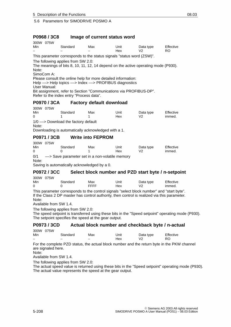
5
5.6 Parameters for SIMODRIVE POSMO A
5-208� Siemens AG 2003 All rights reserved
SIMODRIVE POSMO A User Manual (POS1) – 08.03 Edition
P0968 / 3C8 Image of current status word300W 075WMin Standard Max Unit Data type Effective– – – Hex V2 RO
This parameter corresponds to the status signals ”status word (ZSW)”.The following applies from SW 2.0:The meanings of bits 8, 10, 11, 12, 14 depend on the active operating mode (P930).Note:SimoCom A:Please consult the online help for more detailed information:Help ––> Help topics ––> Index ––> PROFIBUS diagnosticsUser Manual:Bit assignment, refer to Section ”Communications via PROFIBUS-DP”.Refer to the index entry ”Process data”.
P0970 / 3CA Factory default download300W 075WMin Standard Max Unit Data type Effective0 1 1 Hex V2 immed.
1/0 ––> Download the factory defaultNote:Downloading is automatically acknowledged with a 1.
P0971 / 3CB Write into FEPROM300W 075WMin Standard Max Unit Data type Effective0 0 1 Hex V2 immed.
0/1 ––> Save parameter set in a non-volatile memoryNote:Saving is automatically acknowledged by a 0.
P0972 / 3CC Select block number and PZD start byte / n-setpoint300W 075WMin Standard Max Unit Data type Effective0 0 FFFF Hex V2 immed.
This parameter corresponds to the control signals ”select block number” and ”start byte”.If the Class 2 DP master has control authority, then control is realized via this parameter.Note:Available from SW 1.4.The following applies from SW 2.0:The speed setpoint is transferred using these bits in the ”Speed setpoint” operating mode (P930).The setpoint specifies the speed at the gear output.
P0973 / 3CD Actual block number and checkback byte / n-actual300W 075WMin Standard Max Unit Data type Effective– – – Hex V2 RO
For the complete PZD status, the actual block number and the return byte in the PKW channelare signaled here.Note:Available from SW 1.4.The following applies from SW 2.0:The actual speed value is returned using these bits in the ”Speed setpoint” operating mode (P930).The actual value represents the speed at the gear output.
5 Description of the Functions 02.9904.0108.03

5
5.6 Parameters for SIMODRIVE POSMO A
5-209� Siemens AG 2003 All rights reservedSIMODRIVE POSMO A User Manual (POS1) – 08.03 Edition
P0980:78 / 3D4 Supported parameters300W 075WMin Standard Max Unit Data type Effective– – – – I2 RO
All of the parameters supported by the device are listed here in an increasing sequence.P980:0 ––> no significanceP980:1 = 1 (P1)...P980:77 = 990 (P990)
P0990:78 / 3DE Changes with respect to the factory default300W 075WMin Standard Max Unit Data type Effective– – – – I2 RO
All of the parameters which have been changed over the factory default are listed here in anincreasing sequence.P990:0 ––> no significanceP990:1 = 4 (e.g. P4)P990:2 = 990 (P990)P990:3 = after the end of the listNote:For parameters with index, the parameter number is listed if at least 1 parameter of the arraywas changed.
P1426 / 592 Tolerance band for actual setpoint value300WMin Standard Max Unit Data type Effective0 100 3800 rpm C4 immed.
075WMin Standard Max Unit Data type Effective0 100 3600 rpm C4 immed.
”This parameter defines the tolerance band for the actual speed value.If the actual speed value is within this tolerance band around the specified setpoint, the bit”Speed within tolerance band” is output (ZSW.8).Note:This parameter is visible in SimoCom A only in operating mode ”Speed setpoint” (P930).Available with software version 2.0 and higher.
P1427 / 593 Delay time Nsetpoint has elapsed300W 075WMin Standard Max Unit Data type Effective0 0 15000 ms T2 immed.
This parameter defines the delay time following which the bit ”Ramp-up complete” (ZSW.10) isoutput.If the actual speed value for the specified time is within the tolerance band (P1426), ZSW.10 isoutput.Note:This parameter is visible in SimoCom A only in operating mode ”Speed setpoint” (P930).Available with software version 2.0 and higher.
5 Description of the Functions02.9904.0108.03

5
5.6 Parameters for SIMODRIVE POSMO A
5-210� Siemens AG 2003 All rights reserved
SIMODRIVE POSMO A User Manual (POS1) – 08.03 Edition
5.6.3 Gearbox–dependent parameters, factory defaults
Depending on the gearbox used, the parameters listed in Table 5-10are pre–set before the equipment is supplied:
Table 5-10 Gearbox–dependent parameters (factory presetting – default)
Gearbox P964:7 P3 P10 P16 P22 P28
Type
Step–downratio
Gear-box
code
Gearboxstep-
down ratio
Maximumvelocity
Maximumovercur-
rent
Maximumaccel-eration
Maximumcurrent
ratioiGearbox
code – [mm/min] [A] [mm/s2 ] [A]
75 W motor: Gearbox–dependent parameters (factory default)
Without gearbox 2049 1 30000 9.0 1000 9.0
4.5 2050 4.5 6660 9.0 225 7.8
8 2058 8 3750 7.5 125 4.6
Planetary20.25 2059 20.25 1480 9.0 50 9.0
Planetarygearbox
36 2060 36 830 9.0 30 7.9gearbox
50 2061 50 600 8.0 20 5.6
126.5625 2062 126.5625 237 9.0 8 7.8
162 2063 162 185 7.4 6 6.0
5 2064 5 6000 9.0 200 9.0
Worm gear 24 2065 24 1250 7.3 40 7.3Worm gear
75 2066 75 400 5.3 13 5.3
Gearbox–dependentparameters
5 Description of the Functions 02.9904.0105.03

5
5.6 Parameters for SIMODRIVE POSMO A
5-211� Siemens AG 2003 All rights reservedSIMODRIVE POSMO A User Manual (POS1) – 08.03 Edition
Table 5-10 Gearbox–dependent parameters (factory presetting – default), continued
P3 P28P22P16P10P964:7Gearbox
Gear-box
code
Maximumcurrent
Maximumaccel-eration
Maximumovercur-
rent
Maximumvelocity
Gearboxstep-
down ratio
Step–downratio
iGearbox
TypeGear-box
code [A][mm/s2 ][A][mm/min]–
Step–downratio
iGearbox
Type
300 W motor: Gearbox–dependent parameters (factory default)
Keyway20511)
Without
Keyway20672)
Without
gearboxSmoothshaft(without
20751) 1 30000 21.0 4000 21.0gearbox shaft
(withoutkeyway)
20762)
42052
4 7500 21.0 1000 21.042068
4 7500 21.0 1000 21.0
72053
7 4285 21.0 570 21.072069
7 4285 21.0 570 21.0
122054
12 2500 21.0 330 21.0122070
12 2500 21.0 330 21.0
Planetary20
205520 1500 21.0 200 21.0
Planetarygearbox 20
207120 1500 21.0 200 21.0
352056
35 855 12.6 115 14.8352072
35 855 12.6 115 14.8
492057
49 610 9.0 80 10.6492073
49 610 9.0 80 10.6
1202078
120 250 8.3 33 13.01202079
120 250 8.3 33 13.0
1) Upper value ––> gearbox code for the motor without holding brake2) Lower value ––> gearbox code for the motor with holding brake
Notice
After another gearbox type has been mounted, thegearbox–dependent parameters no longer match the gearbox andmust therefore be modified corresponding to Table 5-10.
P964:7 (gearbox code) can only be changed with ”SimoCom A” usingthe drive configuration.
�
5 Description of the Functions02.9904.0105.03

5
5.6 Parameters for SIMODRIVE POSMO A
5-212� Siemens AG 2003 All rights reserved
SIMODRIVE POSMO A User Manual (POS1) – 08.03 Edition
5 Description of the Functions 02.9904.01
Space for your notes

6
6-213� Siemens AG 2003 All rights reservedSIMODRIVE POSMO A User Manual (POS1) – 08.03 Edition
Fault Handling and Diagnostics
6.1 LED fault display
An LED with the following significance is provided on the rear of thepositioning motor for diagnostics LED:
Table 6-1 What does an LED mean when it is bright?
LED display Is thebus
What status does the drive have?What are the fault possibilities?
Color How is it lit?busOK?
What are the fault possibilities?
None Off No � The equipment is powered down or is defective
� The power supply is incorrectly connected (incorrectpolarity)
Red
Steady light No � Critical hardware defect, CPU cannot be used
� Briefly after power up, even if the unit is OK
Disappears after the system has completely run up.Red
Flashing light Yes � Fault present, drive not ready
� Read–out the fault number ––> refer to Chapter 6.2
Red/yellow Alternatingflashing light
No � Bus communications interrupted
Steady light Yes � Standard operation
Green
Flashing light Yes � Run–up, bus being initialized (baud rate adjustment,configuration, parameterization)
� No bus connection established:
– Bus cables not OK
– Address incorrectly set
– Bus parameterizing error
YellowSteady light No � Bus run–up, incorrect configuration telegram
YellowFlashing light No � Bus run–up, incorrect parameterizing telegram
Yellow/green
(fromSW 1.2)
Alternatingflashing light
No � Standalone operation is active
––> refer to Chapter 5.5.12
LEDfault display
6

6
6.2 Faults and warnings
6-214� Siemens AG 2003 All rights reserved
SIMODRIVE POSMO A User Manual (POS1) – 08.03 Edition
6.2 Faults and warnings
6.2.1 General information on faults and warnings
For SIMODRIVE POSMO A, faults and warnings cannot be displayed.
When a fault or warning is detected then this is displayed in the positio-ning motor by setting the appropriate status signal and the fault/war-ning bits in P947, P953 and P954.
The faults and warnings can be evaluated as follows:
� Via PROFIBUS in cycle operation
By reading the status signal and evaluating the bit–coded parametervalues for the faults and warnings (P947, P953 and P954).
� Via SimoCom A in online operation
The faults or warnings that have occurred are converted into an ap-propriate fault/warning number and displayed.
Table 6-2 Overview of faults and warnings
Fault bitWarning bit
Fault numberWarning numberfor SimoCom A
Status signal Significance
P947.0
...
P947.15
700
...
715
ZSW.3
(faults present)
Fault 700
...
Fault 715
P953.0
...
P953.15
800
...
815
ZSW.7
(warning present)
Warning 800
...
Warning 815
P954.0
... (from SW1.4)
P954.15
900
...
915ZSW.3 or ZSW.7
Supplementary information 900
...
Supplementary information 915
Preliminarycomment
6 Fault Handling and Diagnostics 02.9904.01
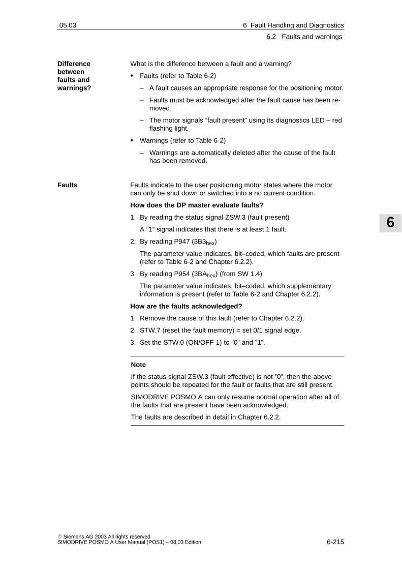
6
6.2 Faults and warnings
6-215� Siemens AG 2003 All rights reservedSIMODRIVE POSMO A User Manual (POS1) – 08.03 Edition
What is the difference between a fault and a warning?
� Faults (refer to Table 6-2)
– A fault causes an appropriate response for the positioning motor.
– Faults must be acknowledged after the fault cause has been re-moved.
– The motor signals ”fault present” using its diagnostics LED – redflashing light.
� Warnings (refer to Table 6-2)
– Warnings are automatically deleted after the cause of the faulthas been removed.
Faults indicate to the user positioning motor states where the motorcan only be shut down or switched into a no current condition.
How does the DP master evaluate faults?
1. By reading the status signal ZSW.3 (fault present)
A ”1” signal indicates that there is at least 1 fault.
2. By reading P947 (3B3hex)
The parameter value indicates, bit–coded, which faults are present(refer to Table 6-2 and Chapter 6.2.2).
3. By reading P954 (3BAhex) (from SW 1.4)
The parameter value indicates, bit–coded, which supplementaryinformation is present (refer to Table 6-2 and Chapter 6.2.2).
How are the faults acknowledged?
1. Remove the cause of this fault (refer to Chapter 6.2.2).
2. STW.7 (reset the fault memory) = set 0/1 signal edge.
3. Set the STW.0 (ON/OFF 1) to ”0” and ”1”.
Note
If the status signal ZSW.3 (fault effective) is not ”0”, then the abovepoints should be repeated for the fault or faults that are still present.
SIMODRIVE POSMO A can only resume normal operation after all ofthe faults that are present have been acknowledged.
The faults are described in detail in Chapter 6.2.2.
Differencebetweenfaults andwarnings?
Faults
6 Fault Handling and Diagnostics02.9904.0105.03

6
6.2 Faults and warnings
6-216� Siemens AG 2003 All rights reserved
SIMODRIVE POSMO A User Manual (POS1) – 08.03 Edition
Warnings indicate to the user motor statues that do not necessarilymean that operation must be interrupted.
How does the DP master evaluate warnings?
1. By reading the status signal ZSW.7 (warning effective)
A ”1” signal indicates that there is at least 1 warning present.
2. By reading P953 (3B9hex)
The parameter value indicates, bit–coded, which warnings are pre-sent (refer to Table 6-2 and Chapter 6.2.2).
3. By reading P954 (3BAhex) (from SW 1.4)
The parameter value indicates, bit–coded, which supplementaryinformation is present (refer to Table 6-2 and Chapter 6.2.2).
Note
If the status signal ZSW.7 (warning effective) is not ”0”, then the abovepoints must be repeated for the warning or warnings that are stillpresent.
Warnings are described in detail in Chapter 6.2.2.
For faults and warnings, measures are described which can be appliedto remove/withdraw the fault/warning.
In this case, one of the possibilities specified is to replace the positio-ning motor. For POSMO A – 300 W, it is also possible, correspondingto the information given as counter–measure, to only change the driveunit.
� Replacing the positioning motor––> refer to Chapter 7.1
� Replacing the drive unit (only POSMO A – 300 W)––> refer to Chapter 7.3.2
Warnings
Remedy
6 Fault Handling and Diagnostics 02.9904.0108.02

6
6.2 Faults and warnings
6-217� Siemens AG 2003 All rights reservedSIMODRIVE POSMO A User Manual (POS1) – 08.03 Edition
6.2.2 List of faults and warnings
Reader’s note
The faults and warnings, listed in the following, are valid for allsoftware releases of SIMODRIVE POSMO A.
The complete list is updated corresponding to the Edition of thedocumentation (refer to the Edition status in the header line) andcorresponds to the software release of SIMODRIVE POSMO Adocumented here.
The individual faults and warnings are not designated as a function ofthe software release.
Version: 04.01.03
700 / P947.0 Overvoltage
Cause The load voltage has exceeded 35 V (75 W motor) or 60 V (300 Wmotor).When braking, the braking energy is excessive which causes an inad-missible increase in the load voltage.
Remedy Provide regenerative feedback protection.
Acknowledgement Remove cause, set STW.7 = 1/0 and STW.0 = 0/1
Stop response Pulse suppression
701 / P947.1 Undervoltage of the load current supply
Cause The load voltage has fallen below 17 V.The load power supply is overloaded.SITOP: The load voltage was powered-down when braking due to over-voltage.
Remedy Increase load power supply rating.SITOP: Provide regenerative feedback protection.
Acknowledgement Remove cause, set STW.7 = 1/0 and STW.0 = 0/1
Stop response Pulse suppression
702 / P947.2 Electronics temperature
Cause The electronics temperature is > 90 degrees Celsius and has been pre-sent for longer than specified in P29 (electronics temperature tolerancetime).An excessive electronics temperature is first signaled using warning800 (warning, electronics temperature).The ambient temperature is too high.
Remedy Observe the de-rating characteristic.Reduce ambient temperature.
Acknowledgement Remove cause, set STW.7 = 1/0 and STW.0 = 0/1
Stop response Braking with maximum acceleration (P22)
6 Fault Handling and Diagnostics02.9908.03

6
6.2 Faults and warnings
6-218� Siemens AG 2003 All rights reserved
SIMODRIVE POSMO A User Manual (POS1) – 08.03 Edition
703 / P947.3 Overcurrent fault
Cause The current limit has been exceeded.The motor or the electronics is defective.
Remedy Replace the positioning motor.
Acknowledgement Remove cause, set STW.7 = 1/0 and STW.0 = 0/1
Stop response Pulse suppression
704 / P947.4 Encoder fault
Cause The signal sequence for the rotor position identification is not permissi-ble.The number of increments between two rotor position signals lies out-side the permissible tolerance.The motor or the electronics is defective.
Remedy Replace the positioning motor.
Acknowledgement Remove cause, set STW.7 = 1/0 and STW.0 = 0/1
Stop response Pulse suppression
705 / P947.5 Standstill monitoring
Cause The motor was moved out of the standstill area (P14) in the closed-loopcontrolled status.Note:The fault can be changed-over to a warning using P30 (fault suppres-sion).
Remedy Check P14 (standstill area).
Acknowledgement Remove cause, set STW.7 = 1/0 and STW.0 = 0/1
Stop response Pulse suppression
706 / P947.6 Software limit switch, start
Cause The actual position lies outside the range defined by the software limitswitch.When traversing to a software limit switch, the motor is always stopped.SW 1.6 and higher: This fault is also signalled if the traversing range limitsof the axis (+/– 200000mm or degrees or inches) are reached. In this case,the Additional information 910 (P954.10) is output.SW 2.0 and higher: This error is also output when the corresponding hard-ware limit switch (start) has been overrun.In this case, additional information 911 (P954.11) is output.Note:The fault can be changed-over to a warning using P30 (fault suppression).
Remedy Move away in the opposite direction.Check P6 (software limit switch, start).
Acknowledgement Remove cause, set STW.7 = 1/0 and STW.0 = 0/1
Stop response Braking with maximum acceleration (P22)
6 Fault Handling and Diagnostics 02.9908.03

6
6.2 Faults and warnings
6-219� Siemens AG 2003 All rights reservedSIMODRIVE POSMO A User Manual (POS1) – 08.03 Edition
707 / P947.7 Software limit switch, end
Cause The actual position lies outside the range defined by the software limitswitch.When traversing to a software limit switch, the motor is always stopped.SW 1.6 and higher: This fault is also signalled if the traversing range limitsof the axis (+/– 200000mm or degrees or inches) are reached. In thiscase, the Additional information 910 (P954.10) is output.SW 2.0 and higher: This error is also output when the corresponding hard-ware limit switch (end) has been overrun.In this case, additional information 911 (P954.11) is output.Note:The fault can be changed-over to a warning using P30 (fault suppression).
Remedy Move away in the opposite direction.Check P7 (software limit switch, end).
Acknowledgement Remove cause, set STW.7 = 1/0 and STW.0 = 0/1
Stop response Braking with maximum acceleration (P22)
708 / P947.8 Speed controller at stop
Cause The speed controller is at its limit for more than 200 ms.The required speed is not reached.The load or friction is too high or the drive is too small.The current limit (P28, P16) is set too low.The drive is defective.Note:The fault can be changed-over to a warning using P30 (fault suppres-sion).
Remedy Reduce load.Increase current limit.Replace the positioning motor.Check the drive parameterization.
Acknowledgement Remove cause, set STW.7 = 1/0 and STW.0 = 0/1
Stop response Pulse suppression
709 / P947.9 Bus communications
Cause Bus communications between the master and slave has failed.The bus cable has been withdrawn or is defectiveThe EMC faults on the bus cable are too high.
Remedy Check fieldbus.
Acknowledgement Remove cause, set STW.7 = 1/0 and STW.0 = 0/1
Stop response Pulse suppression
6 Fault Handling and Diagnostics02.9908.03

6
6.2 Faults and warnings
6-220� Siemens AG 2003 All rights reserved
SIMODRIVE POSMO A User Manual (POS1) – 08.03 Edition
710 / P947.10 Hardware watchdog reset
Cause After a restart, after initiating the CPU monitoring, the positioning motorgoes into a fault condition.Note:The following applies from SW 1.3: Afterwards the positioning motor isno longer referenced.
Remedy Posmo A 75W : Replace the positioning motor.Posmo A 300W : Replace the drive unit.
Acknowledgement Remove cause, set STW.7 = 1/0 and STW.0 = 0/1
Stop response Pulse suppression
711 / P947.11 Flying measurement / actual value setting
Cause The ”flying measurement/actual value setting” function has not beencorrectly parameterized.The bit combination for the program control word (PSW) is illegal.No function is executed.When the function is running, terminal 1 was re-parameterized as out-put. The motion is cancelled and the axis is braked with the maximumdeceleration.
Remedy Check program control word (PSW.9, PSW.10, PSW.11).Check terminal parameterization (P31 = 27 or other input parameteriza-tion).
Acknowledgement Remove cause, set STW.7 = 1/0 and STW.0 = 0/1
Stop response Pulse suppression
712 / P947.12 Holding brake, undervoltage
Cause At least the following voltage characteristics are required in order toopen and hold the integrated holding brake:Open Load power supply > 24 VStop Load power supply > 18 VThe drive is stopped if the load power supply voltage is too low.Note:This fault can be disabled for a motor without holding brake (P56.5 = 0).
Remedy Check the load power supply and increase rating.
Acknowledgement Remove cause, set STW.7 = 1/0 and STW.0 = 0/1
Stop response Pulse suppression
713 / P947.13 Reference position lost
Cause During shutdown, the drive was in motion. Therefore, the referencepositon has not been accepted. The drive is not referenced.
Remedy Reference drive.
Acknowledgement Remove cause, set STW.7 = 1/0 and STW.0 = 0/1
Stop response Pulse suppression
6 Fault Handling and Diagnostics 02.9908.03
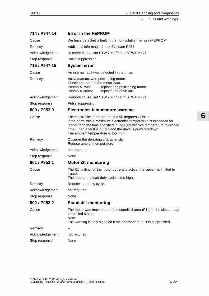
6
6.2 Faults and warnings
6-221� Siemens AG 2003 All rights reservedSIMODRIVE POSMO A User Manual (POS1) – 08.03 Edition
714 / P947.14 Error in the FEPROM
Cause We have detected a fault in the non-volatile memory (FEPROM).
Remedy Additional information? ––> Evaluate P954
Acknowledgement Remove cause, set STW.7 = 1/0 and STW.0 = 0/1
Stop response Pulse suppression
715 / P947.15 System error
Cause An internal fault was detected in the drive.
Remedy Activate/deactivate positioning motor. Check and correct the motor data.Posmo A 75W: Replace the positioning motor.Posmo A 300W: Replace the drive unit.
Acknowledgement Remove cause, set STW.7 = 1/0 and STW.0 = 0/1
Stop response Pulse suppression
800 / P953.0 Electronics temperature warning
Cause The electronics temperature is > 90 degrees Celsius.If the permissible maximum electronics temperature is exceeded forlonger than the time specified in P29 (electronics temperature tolerancetime), then a fault is output and the drive is powered-down.The ambient temperature is too high.
Remedy Observe the de-rating characteristic.Reduce ambient temperature.
Acknowledgement not required
Stop response None
801 / P953.1 Motor i2t monitoring
Cause The I2t limiting for the motor current is active, the current is limited toIrated.The load or the load duty cycle is too high.
Remedy Reduce load duty cycle.
Acknowledgement not required
Stop response None
802 / P953.2 Standstill monitoring
Cause The motor was moved out of the standstill area (P14) in the closed-loopcontrolled status.Note:The warning is only signaled if the appropriate fault is suppressed.
Remedy –
Acknowledgement not required
Stop response None
6 Fault Handling and Diagnostics02.9908.03

6
6.2 Faults and warnings
6-222� Siemens AG 2003 All rights reserved
SIMODRIVE POSMO A User Manual (POS1) – 08.03 Edition
803 / P953.3 Software limit switch, start
Cause The actual position lies outside the range defined by the software limitswitch.When traversing to a software limit switch, the motor is always stopped.SW 1.6 and higher: This warning is also signalled if the traversing rangelimits of the axis (+/– 200000mm or degrees or inches) are reached. Inthis case, the additional information 910 (P954.10) is output.SW 2.0 and higher: This warning is also output when the correspondinghardware limit switch (start) has been overrun.In this case, additional information 911 (P954.11) is output.Note:The warning is only signaled if the appropriate fault is suppressed.
Remedy Move away in the opposite direction.Check P6 (software limit switch, start).
Acknowledgement not required
Stop response None
804 / P953.4 Software limit switch, end
Cause The actual position lies outside the range defined by the software limitswitch.When traversing to a software limit switch, the motor is always stopped.SW 1.6 and higher: This warning is also signalled if the traversing rangelimits of the axis (+/– 200000mm or degrees or inches) are reached. Inthis case, the additional information 910 (P954.10) is output.SW 2.0 and higher: This warning is also output when the correspondinghardware limit switch (end) has been overrun.In this case, additional information 911 (P954.11) is output.Note:The warning is only signaled if the appropriate fault is suppressed.
Remedy Move away in the opposite direction.Check P7 (software limit switch, end).
Acknowledgement not required
Stop response None
805 / P953.5 Jogging: Jogging not possible
Cause Drive not enabled.Jogging already selected.Traversing block being processed.Note:Additional information? ––> evaluate P954
Remedy –
Acknowledgement not required
Stop response None
6 Fault Handling and Diagnostics 02.9908.03

6
6.2 Faults and warnings
6-223� Siemens AG 2003 All rights reservedSIMODRIVE POSMO A User Manual (POS1) – 08.03 Edition
806 / P953.6 Referencing: Position not accepted
Cause When referencing, the position was not accepted.Motor moving (ZSW.13 = 1).Drive not enabled.Traversing block being processed.After power-on: The motor has still not moved.Note:Additional information? ––> evaluate P954
Remedy The motor must be stationary and closed-loop controlled.
Acknowledgement not required
Stop response None
807 / P953.7 Speed controller at stop
Cause The speed controller is at its limit for more than 200 ms.The required speed is not reached.The load or friction is too high or the drive is too small.The current limit (P28, P16) is set too low.The drive is defective.For the ”traverse to fixed endstop” function, this warning is output whenthe fixed endstop is reached.Note:The warning is only signaled if the appropriate fault is suppressed.
Remedy Reduce load.Increase current limit.Replace the positioning motor.
Acknowledgement not required
Stop response None
808 / P953.8 Start absolute block not possible
Cause A block with absolute position data can only be started for a referenceddrive.
Remedy Reference drive.
Acknowledgement not required
Stop response None
6 Fault Handling and Diagnostics02.9908.03

6
6.2 Faults and warnings
6-224� Siemens AG 2003 All rights reserved
SIMODRIVE POSMO A User Manual (POS1) – 08.03 Edition
809 / P953.9 Program cannot be started
Cause Drive not enabled.Invalid block number selected.Enable signals missing.A traversing block is already being processed.STW.11 (start referencing) is set.Traversing block with absolute position data and drive not referenced.Positioning mode not enabled (STW.4, STW.5)Note:Additional information? ––> evaluate P954
Remedy –
Acknowledgement not required
Stop response None
810 / P953.10 Invalid program selection
Cause An attempt was made to either select block 0 or a block > 27.
Remedy Select valid block (1 to 27).
Acknowledgement not required
Stop response None
811 / P953.11 Speed limiting active
Cause The required axis velocity requires a higher speed than that specified inP8 (max. speed).Up to SW 1.5:The velocity is limited to the maximum speed.SW 1.6 and higher:P24 ”Override speed” is limited so that maximum speed is used.
Remedy Enter lower velocity.Adapt P10 (max. velocity).Adapt P8 (max. speed).
Acknowledgement not required
Stop response None
812 / P953.12 Undervoltage of the load current supply
Cause SW 1.6 and higher:The load voltage has fallen below 17 V.The load power supply is overloaded.SITOP: The load voltage was powered-down when braking due to over-voltage.
Remedy Increase load power supply rating.SITOP: Provide regenerative feedback protection.
Acknowledgement not required
Stop response None
6 Fault Handling and Diagnostics 02.9908.03

6
6.2 Faults and warnings
6-225� Siemens AG 2003 All rights reservedSIMODRIVE POSMO A User Manual (POS1) – 08.03 Edition
900 / P954.0 Operation not enabled
Cause Bits to enable the drive missing.
Remedy Set enable signals in the control word (STW).
Acknowledgement not required
Stop response None
901 / P954.1 Illegal operating status
Cause If the program is running, jogging or referencing is not possible.
Remedy –
Acknowledgement not required
Stop response None
902 / P954.2 Single block active
Cause If the program is running and in the single block mode, jogging orreferencing is not possible.
Remedy –
Acknowledgement not required
Stop response None
903 / P954.3 Both jogging signals active
Cause –
Remedy –
Acknowledgement not required
Stop response None
904 / P954.4 Positioning mode not enabled
Cause Operating condition for program missing (STW.4).
Remedy –
Acknowledgement not required
Stop response None
905 / P954.5 Axis has still not been moved
Cause The axis was still not moved after power-on.
Remedy –
Acknowledgement not required
Stop response None
6 Fault Handling and Diagnostics02.9908.03

6
6.2 Faults and warnings
6-226� Siemens AG 2003 All rights reserved
SIMODRIVE POSMO A User Manual (POS1) – 08.03 Edition
906 / P954.6 FEPROM error upon writing or deletion
Cause Presumably, there is a hardware fault in the non-volatile memory (FEPROM).
Remedy Replace the positioning motor.
Acknowledgement not required
Stop response None
907 / P954.7 FEPROM No positional data available
Cause In order to restart, the drive requires positional data. This has not beensaved correctly upon the last ramp-down.
Remedy If necessary, reference the drive.Activate/deactivate positioning motor. Replace the positioning motor.
Acknowledgement not required
Stop response None
908 / P954.8 FEPROM No factory setting available
Cause Presumably, there is a hardware fault in the non-volatile memory (FEPROM).
Remedy Replace the positioning motor.
Acknowledgement not required
Stop response None
909 / P954.9 FEPROM No user parameters available
Cause Presumably, the drive was deactivated when saving the user parame-ters into the non-volatile memory (FEPROM). There may also be a hardware fault in the non-volatile memory (FEPROM).
Remedy Check and correct the motor data.Restore the data in the FEPROM.Replace the positioning motor.
Acknowledgement not required
Stop response None
910 / P954.10 Traversing range limit reached
Cause Axis has reached a traversing range limit. The traversing range limits of the axis are +/– 200000mm or degrees orinches.
Remedy For drives turning endlessly, a modulo value must be entered in Para-meter 1.
Acknowledgement not required
Stop response None
6 Fault Handling and Diagnostics 02.9908.03

6
6.2 Faults and warnings
6-227� Siemens AG 2003 All rights reservedSIMODRIVE POSMO A User Manual (POS1) – 08.03 Edition
911 / P954.11 Hardware limit switch crossed/reached
Cause The axis has reached or crossed a hardware limit switch.The exact limit switch is defined by the simultaneously output error orwarning of the software limit switch.
Remedy Acknowledge fault. Continued travel in opposite direction.Note:Continued travel is generally only possible in the opposite direction.If the hardware limit switch is crossed, continued travel in the originaldirection is only possible if travel continues in the opposite directionfollowing fault acknowledgement and if the hardware switch is crossedagain.This ensures that the axis is within the permitted traversing range.
Acknowledgement not required
Stop response None
6 Fault Handling and Diagnostics02.9908.03

6
6.3 Analog test outputs
6-228� Siemens AG 2003 All rights reserved
SIMODRIVE POSMO A User Manual (POS1) – 08.03 Edition
6.3 Analog test outputs
Analog test outputs are provided at the rear of the SIMODRIVEPOSMO A which are only accessible after the cover has beenunscrewed.
!Caution
Measurements may only be made in exceptional cases byappropriately trained personnel. The ”correct” text sockets must beused, as short–circuits will permanently damage the module (refer toFig. 6-1).
The following parameters are available for the analog testsockets:
� P33, P34, P35 address, shift factor and offset for DAU 1
� P36, P37, P38 address, shift factor and offset for DAU 2
Which signal is output via the test outputs?
� This is defined by entering an appropriate address in P33 or P36.
Test sockets: 0.64 mm
Pin 123
5 V
2.5 V � 0 V of the test signal
0 V
Test pins
0.64
Screw type: Counter–sunk screwM4 x 12 – 8.8SN 63261
SIMODRIVE POSMO Awith cover attached
SIMODRIVE POSMO Awith cover removed
2.54 2.54
X11
––> 75 W motorPin 321 ––> 300 W motor
Torx T15/80
max. 3.9 Nm
Pin Function
1 DAU 1
2 DAU 2
3 M (reference)
Fig. 6-1 SIMODRIVE POSMO A test sockets with the cover removed
Description
6 Fault Handling and Diagnostics 02.9904.01
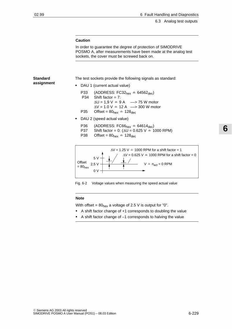
6
6.3 Analog test outputs
6-229� Siemens AG 2003 All rights reservedSIMODRIVE POSMO A User Manual (POS1) – 08.03 Edition
Caution
In order to guarantee the degree of protection of SIMODRIVEPOSMO A, after measurements have been made at the analog testsockets, the cover must be screwed back on.
The test sockets provide the following signals as standard:
� DAU 1 (current actual value)
P33 (ADDRESS: FC32hex � 64562dec) P34 Shift factor = 7:
∆U = 1,9 V � 9 A ––> 75 W motor∆V = 1.0 V � 12 A ––> 300 W motor
P35 Offset = 80hex � 128dec
� DAU 2 (speed actual value)
P36 (ADDRESS: FC66hex � 64614dec)P37 Shift factor = 0: (∆U = 0.625 V � 1000 RPM)P38 Offset = 80hex � 128dec
5 VOffset= 80hex
0 V
2.5 V V � nact = 0 RPM
∆V = 1.25 V � 1000 RPM for a shift factor = 1∆V = 0.625 V � 1000 RPM for a shift factor = 0
Fig. 6-2 Voltage values when measuring the speed actual value
Note
With offset = 80hex a voltage of 2.5 V is output for ”0”.
� A shift factor change of +1 corresponds to doubling the value
� A shift factor change of –1 corresponds to halving the value
Standardassignment
6 Fault Handling and Diagnostics02.99

6
6.4 Bus monitor AMPROLYZER for PROFIBUS DP
6-230� Siemens AG 2003 All rights reserved
SIMODRIVE POSMO A User Manual (POS1) – 08.03 Edition
The following supplementary addresses are available:
� Speed setpoint:FC00hex � 64512dec the same normalization as the speed
actual value
� Position actual value:FC6Ahex � 64618decshift factor= 6: 1 motor revolution � 4 V ––> 75 W motor= 4: 1 motor revolution � 5 V ––> 300 W motor
� Iset (n controller):FC38hex � 64568dec the same normalization as the current
actual value
� Iset (smoothed):FC3Ahex � 64570dec the same normalization as the current
actual value
Reader’s note
The signals are shown in Chapter 3.3.1.
6.4 Bus monitor AMPROLYZER for PROFIBUS DP
The AMPROLYZER bus monitor can be used to diagnose, monitor andtrace data transfer in PROFIBUS networks.
AMPROLYZER (Advanced Multicard PROFIBUS Analyzer)
The software is freeware and is available from the Internet as follows:
––> http://www.ad.siemens.de/simatic-cs
––> search for the article number 338386
The self–extracting EXE file can be downloaded.
For more information on the AMPROLYZER bus monitor, please referto the information in the Internet and the files supplied.
�
Additionalpossible addresses
Description
Internet address
6 Fault Handling and Diagnostics 02.9908.02

7
7-231� Siemens AG 2003 All rights reservedSIMODRIVE POSMO A User Manual (POS1) – 08.03 Edition
Installation and Service
7.1 Replacing the motor
We recommend the following procedure when the positioning motorhas to be replaced:
1. Save the parameters of the SIMODRIVE POSMO A.
The parameters will be required again for the new motor.
2. Cancel the pulses: Control signal STW.1 (OFF 2) = 0
3. Power–down the load and electronics power supplies.
4. Release the connection cover of the positioning motor and remove(2 screws).
Protect the connection cover and the motoragainst dirt – cover all of the open components.
5. Unscrew the complete defective positioning motor together with thegearbox.
6. Bolt on the new complete SIMODRIVE POSMO A.
7. Release and withdrawn the connection cover of the newSIMODRIVE POSMO A (2 screws).
Protect the connection cover and the positioning motoragainst dirt – cover all of the open components.
8. Locate the wired ”old” cover on the new positioning motor which hasbeen bolted into place and tighten the screws (2 screws).
9. Power–up the load and electronics power supplies.
10.Re–load the parameters saved under the first point.
11.Check: Does the positioning motor run fault–free?
– if yes ––> then the ”old” connection cover is O. K.
– if no ––> the ”old” connection cover may be defective;replace the connection cover
12.Screw the connection cover back onto the positioning motor.
13.Return to the following address.
Replacing themotor
7

7
7.1 Replacing the motor
7-232� Siemens AG 2003 All rights reserved
SIMODRIVE POSMO A User Manual (POS1) – 08.03 Edition
You can also obtain the address of your local regional spare parts cen-ter at the following Internet address
� Address: http://www3.ad.siemens.de/partner
� Product group: SIMODRIVE
Note
If the ”old” connection cover of the SIMODRIVE POSMO A is notdefective, then it should be left at the mounting location and shouldthen be re–mounted on the ”new” positioning motor with the existingwiring.
Addresses toreturn thepositioning motor
7 Installation and Service 04.0108.02

7
7.2 Mounting or replacing a gearbox (only relevant for 300 W motors)
7-233� Siemens AG 2003 All rights reservedSIMODRIVE POSMO A User Manual (POS1) – 08.03 Edition
7.2 Mounting or replacing a gearbox (only relevant for 300 Wmotors)
The following materials and tools are required to mount or replace agearbox:
1. Four retaining screws per motor (M6 x 20 acc. to DIN 6912)
2. Tools: SW 4 and SW 5 Allen keys
3. Sealing agent: (e.g. Fluid D from Teroson)
4. Loctite: (e.g. Loctite Type 649)
5. Solvent: (e.g. Sevenax 72)
6. New gearbox: refer to the modular gearboxes in Chapter 2.5.2
The following preparations must be made before mounting or changinggearboxes:
� This point is only valid if the gearbox is be replaced
– Remove the cover from the mounting hole
– Rotate the clamping hub with respect to the adapter plate inorder to line–up the mounting holes
– Release the clamping hub coupling of the gearbox
– Release the 4 screws between the motor and gearbox
– Remove the gearbox
� Prepare the gearbox to be mounted
– Clean the opening for the gearbox input shaft
– Clean the mounting surface and remove any possible damage(e.g. impressions in the mating surfaces, burs)
� Preparing the motor
– Clean the motor shaft
– Clean the mounting surface and remove any possible damage(e.g. impressions in the mating surfaces, burs)
– Apply a sealing agent to the motor flange
What is required tomount or replacegearboxes?
What preparationshave to be made?
7 Installation and Service04.0108.01

7
7.2 Mounting or replacing a gearbox (only relevant for 300 W motors)
7-234� Siemens AG 2003 All rights reserved
SIMODRIVE POSMO A User Manual (POS1) – 08.03 Edition
When mounting a gearbox, proceed as follows:
1. Carefully locate the gearbox on the motor by applying gentle pres-sure until there is no longer a gap between the motor and gearbox.
2. Tighten the clamping hub coupling
– Tool: Allen key SW 4
– Torque: max. 6 Nm
3. Establish the connection between the motor and gearbox
– Tool: Allen key SW 5
– Tighten the screws diagonally
– Torque: max. 5 Nm �10 %
4. Secure the screws (Loctite)
Notice
If another gearbox has been mounted, the gearbox–dependentparameters no longer match the gearbox being used and theseparameters must be appropriately changed.
––> Refer to Chapter 5.6.3
What are the stepswhen mounting agearbox?
7 Installation and Service 04.01

7
7.3 Spare parts for SIMODRIVE POSMO A
7-235� Siemens AG 2003 All rights reservedSIMODRIVE POSMO A User Manual (POS1) – 08.03 Edition
7.3 Spare parts for SIMODRIVE POSMO A
7.3.1 List of spare parts for the 300 W motors
The following spare parts are available for SIMODRIVE POSMO A –300 W:
� Drive unit 6SN2157-0AA01-0BA0
� Planetary gear, degree of protection IP54
– Planetary gear i = 4 EWN:5293200001000
– Planetary gear i = 7 EWN:5293200002000
– Planetary gear i = 12 EWN:5293200021000
– Planetary gear i = 20 EWN:5293200022000
– Planetary gear i = 35 EWN:5293200023000
– Planetary gear i = 49 EWN:5293200024000
– Planetary gear i = 120 EWN:5293200131000
� Planetary gear, degree of protection IP65
– Planetary gear i = 4 EWN:5293200011000
– Planetary gear i = 7 EWN:5293200012000
– Planetary gear i = 12 EWN:5293200031000
– Planetary gear i = 20 EWN:5293200032000
– Planetary gear i = 35 EWN:5293200033000
– Planetary gear i = 49 EWN:5293200034000
What spare partsare there?
7 Installation and Service04.0105.03

7
7.3 Spare parts for SIMODRIVE POSMO A
7-236� Siemens AG 2003 All rights reserved
SIMODRIVE POSMO A User Manual (POS1) – 08.03 Edition
7.3.2 Drive unit as spare part (only the 300 W motor)
We recommend the following procedure if a drive unit is to replaced:
SW 3
4 (1.0 x 6.5)
Connection cover
Drive unit
Motor
Gearbox
2 slotted screws
4 self–tapping Allen keys
M4 x 16
2.5 – 3 Nm
not to scale
Fig. 7-1 Replacing the drive unit
Reader’s note
This Chapter – replacing the drive unit – is current at the time that thisManual was published.
Up–to–date and binding information on this subject should be takenfrom the documentation provided with the spare parts ”Installation andmounting instructions, replacing the drive unit”.
Replacing thedrive unit
7 Installation and Service 04.0108.02

7
7.3 Spare parts for SIMODRIVE POSMO A
7-237� Siemens AG 2003 All rights reservedSIMODRIVE POSMO A User Manual (POS1) – 08.03 Edition
The following are required to replace the drive unit:
1. Tools
– Screwdriver Size 4 (1.0 x 6.5)
– Allen key SW 3
2. New drive unit
3. Parameter sets of the old drive unit (save and make available)
The drive unit is replaced as follows:
Caution
The positioning motor must be brought into a no–voltage conditionbefore the drive unit is replaced.
1. Remove the connection cover
– Tool Screwdriver, Size 4 (1.0 x 6.5)
2. Release the four screws retaining the drive unit
– Tool Allen key SW 3
3. Remove the old drive unit
4. Mount the new drive unit
5. Tighten the four screws retaining the drive unit
– Tool Allen key SW 3
– Tighten the screws diagonally
– Tightening torque 2.5 – 3 Nm
6. Locate the connection cover and tighten the screws
– Tool Screwdriver, Size 4 (1.0 x 6.5)
7. Load the parameter set
The parameter set provided must be downloaded into the new driveunit from the old drive unit.
8. Test the positioning motor
The spare drive unit has the following Order No:
Order No. (MLFB): 6SN2157-0AA01-0BA0
Refer to Chapter 7.1 under ”Address to return the positioning motor” forthe address of the regional spare parts department that is responsiblefor you.
�
What is required toreplace the driveunit?
How do youreplace the driveunit?
Order No.
Address to returnthe drive unit (300W motor)
7 Installation and Service04.0108.0208.02

7
7.3 Spare parts for SIMODRIVE POSMO A
7-238� Siemens AG 2003 All rights reserved
SIMODRIVE POSMO A User Manual (POS1) – 08.03 Edition
7 Installation and Service 04.01
Space for your notes

A
A-239� Siemens AG 2003 All rights reservedSIMODRIVE POSMO A User Manual (POS1) – 08.03 Edition
Abbreviations
Output
Absolute
Alternating Current
Task or response ID
Actual block number: Part of the status signals
Advanced Multicard PROFIBUS Analyzer: Bus monitor for PROFIBUS
Select block number: Part of the control signals
Abbreviation for binary number
Brushless Direct Current: Permanent–magnet brushless servomotor
PROFIBUS master, Class 1
PROFIBUS master, Class 2
PROFIBUS parameter format
Communications module
Communication processor
Central Processing Unit
Direct Current
Abbreviation for decimal number
Dual-In-Line
Distributed Periphery
DP Master Class 1, 2 DP-Master Class 1, 2
Electromagnetic compatibility
European Standard
Program memory with fixed program
Module/components endangered by electrostatic discharge
Electrostatic Discharge Sensitive Devices
Function Block
Flash-EPROM: Memory which can be read and written into
Firmware
A
ABS
AC
AK
AktSatz
AMPROLYZER
AnwSatz
Bin
BLDC
C1 master
C2 master
C4
COM
CP
CPU
DC
Dec
DIL
DP
DPMC1, 2
EMC
EN
EPROM
ESD
ESDS
FB
FLASHEPROM
FW
A

A
A-240� Siemens AG 2003 All rights reserved
SIMODRIVE POSMO A User Manual (POS1) – 08.03 Edition
Master device file: describes the features of a DP slave
Abbreviation for a hexadecimal number
Hardware
Hardware limit switch
Gearbox step–down ratio
Input
PROFIBUS parameter format
PROFIBUS parameter format
Input byte
Start–up
International Electrotechnical Commission
Input
Sub–index, Sub–parameter number array index: Part of a PKW
Integer: Integer number
Input word
Position loop gain (Kv factor)
Light Emitting Diode
Fiber–optic cable
Ground
Mega byte
Manual Data Input
Machine Readable Product Designation: Order No.
Multi Point Interface: Multi–point serial interface
Measuring system grid
PROFIBUS parameter format
Speed actual value
Standard zero (average sea level)
Speed setpoint
Output byte
Enable
Output
Output word
Parameter
Peripheral output byte
GSD
HEX
HW
HWE
i
I
I2
I4
IB
IBN
IEC
IN
IND
INT
IW
Kv
LED
LWL
M
MB
MDI
MLFB
MPI
MSR
N2
nact
NN
nset
OB
OC
Out
OW
P
PAB
A Abbreviations 04.01

A
A-241� Siemens AG 2003 All rights reservedSIMODRIVE POSMO A User Manual (POS1) – 08.03 Edition
Peripheral output word
Personal Computer
Peripheral input byte
Protective Extra Low Voltage The protective low voltage PELV must have protective separation, begrounded and shockproof
Peripheral input word
Programming device
Parameter identification: Part of a PKW
Parameter identification value: Parameterizing part of a PPO
Programmable logic controller (e.g. SIMATIC S7)
Power Management Module
PROFIBUS User Organization
Parameter numbers
POWER ON
Positioning Motor Actuator: Positioning motor
Parameter process data object: Cyclic data telegram when transferring data using PROFIBUS–DP andthe ”variable–speed drives” profile
Process Field Bus: Serial data bus
Power supply
Supply voltage
Program control word
Process data: Process data section of a PPO
Output
Random Access MemoryProgram memory which can be read and written into
Relative
Checkback signal byte
Read Only
Continuous duty
Intermittent duty
Siemens Standard
Block number
Interface
PAW
PC
PEB
PELV
PEW
PG
PKE
PKW
PLC
PMM
PNO
PNU
PO
POSMO A
PPO
PROFIBUS
PS
PS
PSW
PZD
Q
RAM
REL
RMB
RO
S1
S3
SN
SNR
SS
A Abbreviations04.01

A
A-242� Siemens AG 2003 All rights reserved
SIMODRIVE POSMO A User Manual (POS1) – 08.03 Edition
Start byte
Control word
Software x.y
Size x mm
Software limit switch
PROFIBUS parameter format
Terminals
Verband Deutscher Elektrotechniker [Association of German ElectricalEngineers]
Verein Deutscher Ingenieure [Association of German Engineers]
Position actual value
Position setpoint value
Status word
�
STB
STW
SW x.y
SW x
SWE
T4
Term.
VDE
VDI
xact
xset
ZSW
A Abbreviations 04.01

B
B-243� Siemens AG 2003 All rights reservedSIMODRIVE POSMO A User Manual (POS1) – 08.03 Edition
References
General Documentation
Catalog DA 65.4 � 2001SIMODRIVE 611 universal and POSMOOrder No.: E86060–K5165–A401–A1
Catalog NC 60 � 2002Automation Systems for Machine ToolsOrder No.: E86060–K4460–A101–A9Order No.: E86060–K4460–A101–A9 –7600 (English)
Catalog NC ZConnection System & System ComponentsOrder No.: E86060–K4490–A001–A8Order No.: E86060–K4490–A001–A8–7600 (English)
SIMATICSIMATIC S7 Programmable Logic ControllersCatalog ST 70Order No.: E86 060–K4670–A111–A3
SITOP power, Power SuppliesCatalog KT 10.1 1999Order No.: E86060–K2410–A101–A3
SITOP modular 48V/20A Power Supplies (6EP1 457–3BA00)Operating Instructions 07.2002Order No.: C98130–A7552–A1–1–6419
Automation with STEP 7 in STL SIMATIC S7–300/400 Programmable Logic ControllersSIEMENS; Publicis MCD Verlag; Hans BergerOrder No.: A19100–L531–B665
ISBN 3–89578–036–7
/KT654/
/KT60/
/Z/
/ST7/
/KT101/
/SI1/
/STEP7/
B

B
B-244� Siemens AG 2003 All rights reserved
SIMODRIVE POSMO A User Manual (POS1) – 08.03 Edition
Electronic Documentation
The SINUMERIK System (11.03 Edition)DOC ON CD(including all SINUMERIK 840D/840Di/810D/FM–NC and SIMODRIVEdocuments)Order No.: 6FC5 298–7CA00–0BG0
Documentation for PROFIBUS
Catalog IK PI � 2000Industrial Communications and Field DevicesOrder No. of the bound edition: E86060–K6710–A101–A9Order No. of the loose–leaf edition: E86060–K6710–A100–A9
PROFIBUS–DPV1, Basics, Tips and Tricks for UsersHüthig; Manfred PoppEN50170ISBN 3–7785–2781–9
PROFIBUS–DP, Fast EntryPROFIBUS User Organisation e.V.; Manfred PoppOrder No.: 4.071
PROFIBUS, Profile for Variable–Speed Drives, PROFIDRIVESeptember 1997 EditionPROFIBUS User Organization e.V.76131 Karlsruhe, Haid–and–Neu–Straße 7;Order No.: 3.071
Decentralization with PROFIBUS–DPDesign, Configuring andUsing PROFIBUS–DP with SIMATIC S7SIEMENS; Publics MCD Verlag; Josef Weigmann, Gerhard KilianOrder No.: A19100–L531–B714ISBN 3–89578–123–1
Manual for PROFIBUS NetworksSIEMENS;Order No.: 6GK1 970–5CA10–0AA0
/CD1/
/IKPI/
/P1/
/P2/
/P3/
/P4/
/P5/
B References 05.03

B
B-245� Siemens AG 2003 All rights reservedSIMODRIVE POSMO A User Manual (POS1) – 08.03 Edition
Manufacturer/Service Documentation
SIMODRIVE POSMO A (08.03 Edition)User ManualOrder No.: 6SN2 197–0AA00–0BP6
SIMODRIVE POSMO A (08.03 Edition)Installation Instructions 75/300 W motor (is provided with each drive)Order No.: A5E00158596 ab
SIMATIC S7–300 (2002 Edition)– Reference Manual: CPU data (HW description)– Reference Manual: Module data– Manual, technological functions– Installation ManualOrder No.: 6ES7 398–8FA10–8AA0
SIMATIC S7–300 (03.97 Edition)Manual: STEP 7, Basic Know–How, V. 3.1Order No.: 6ES7 810–4AC02–8AA0
SIMATIC S7–300 (03.97 Edition)Manual: STEP 7, Reference Manuals, V. 3.1Order No.: 6ES7 810–4CA02–8AR0
SIMATIC (05.01 Edition)Distributed ET 200X I/O DevicesManual EWA 4NEB 780 6016–01 04Part of the package with Order No.6ES7 198–8FA01–8AA0
SINUMERIK, SIROTEC, SIMODRIVE (06.99 Edition)EMC GuidelinesPlanning Guide (HW)Order No.: 6FC5 297–0AD30–0BP1
The current Declaration of Conformity is in the Internet under http://www4.ad.siemens.de
Please enter the ID NO: 15257461 in the field ’Search’ (top right) andthen click on ’go’.
�
/POS1/
/POS2/
/S7H/
/S7HT/
/S7HR/
/ET200X/
/EMV/
B References05.03

B
B-246� Siemens AG 2003 All rights reserved
SIMODRIVE POSMO A User Manual (POS1) – 08.03 Edition
B References 05.03
Space for your notes

C
C-247� Siemens AG 2003 All rights reservedSIMODRIVE POSMO A User Manual (POS1) – 08.03 Edition
Dimension Drawings
C.1 Dimension drawings for SIMODRIVE POSMO A – 75 W
The dimension drawings for the SIMODRIVE POSMO A – 75 W posi-tioning motor with the following gearboxes are provided in this Section:
� Motor without gearbox ––> refer to Fig. C-1
� Motor with planetary gearbox, stages 1, 2, 3 ––> refer to Fig. C-2
� Motor with worm gearbox ––> refer to Fig. C-3
Contents
C

C
C.1 Dimension drawings for SIMODRIVE POSMO A – 75 W
C-248� Siemens AG 2003 All rights reserved
SIMODRIVE POSMO A User Manual (POS1) – 08.03 Edition
0.2
A
0.
2 A
0.2
A
PRO/E–CAD
The
rep
rodu
ctio
n, tr
ansm
issi
on o
r us
e of
this
doc
umen
t or
itsco
nten
ts is
not
per
mitt
ed w
ithou
t exp
ress
writ
ten
auth
ority
.O
ffend
ers
will
be
liabl
e fo
r da
mag
es. A
ll rig
hts,
incl
udin
g rig
hts
crea
ted
by p
aten
t gra
nt o
r re
gist
ratio
n of
a u
tility
mod
el o
r de
sign
,ar
e re
serv
ed.
Wei
terg
abe
sow
ie V
ervi
elfä
ltigu
ng d
iese
r U
nter
lage
, Ver
wer
–tu
ng u
nd M
ittei
lung
ihre
s In
halts
nic
ht g
esta
ttet,
sow
eit
nich
tau
sdrü
cklic
h zu
gest
ande
n. Z
uwid
erha
ndlu
ngen
ver
pflic
hten
zu S
chad
ener
satz
. Alle
Rec
hte
vorb
ehal
ten,
insb
eson
dere
für
den
Fal
l der
Pat
ente
rtei
lung
ode
r G
M–E
intr
agun
g.
Con
fie a
titr
e de
sec
ret d
’ ent
repr
ise.
Tou
s dr
oits
res
erve
s
Con
fiado
com
o se
cret
o in
dust
ial.
Nos
res
erva
mos
todo
s lo
s de
rech
os
Com
unic
ado
com
o se
gred
o em
pres
aria
l. R
eser
vado
s to
dos
os d
ireito
s
’’
’
* P
ro/E
*2
Bel
ongi
ng to
this
:
13
45
EDCBA
12
3
CA
D–D
raw
ing
Man
ual m
odifi
catio
npr
ohib
ited
45
67
8
EDCBA
Con
d.M
essa
geD
ate
Nam
e
Sie
men
s A
G
Dep
t.
Sta
ndar
d
Test
ed b
y
Han
dled
by
Dat
e
Sca
le:
Typ
e/M
LFB
:
Pag
e:
P.
Rep
lace
men
t for
/ re
plac
ed b
y:
F
A&
D
Equ
ipm
ent P
lant
Erla
ngen
DIN
6
2 –0.
3
Gen
eral
tole
ranc
e
Sur
face
:1:
1kg
/pie
ce:
ISO
276
8–m
k.
.
Tole
ranc
e.
.
.IS
O 8
015
.
..
04.0
8.98
Lehn
erS
IMO
DR
IVE
PO
SM
O A
– 7
5WM
asat
zw
ithou
t ge
arbo
xM
C E
45
ac79
A48
128
17.0
7.03
Mü
ab79
A19
137
02.0
3.01
Kn
2 G
E.
5660
28.9
000.
00M
Bac
1aa
5011
5604
.08.
98F
e1
M4
1.8
16M
53.
026
Anz
iehd
rehm
omen
tTi
ghte
ning
tor
que
Nm
inlb
BP
g 11
dum
my
plug
s, T
ype
514/
11
Pfli
tsch
–––
AP
g13.
5 th
read
ed jo
int
HS
K M
EM
V
Hum
mel
12.0
–6.0
Pg–
Ver
schr
aubu
ng
Pg
thre
aded
join
t
Typ
e
Type
Kab
el–ø
cabl
e–ø
AB
BA
M4
M5
M5
A
71±
1
40±
0.1
49
±0.
1
36±
0.1
100±163±1
147
±1
11±
0.5
8+0.005 –0.011
63±0.5
25 –0.04
125
±0.
8
59±
0.7
124
±0.
5
M0.
7 de
ep5
M0.
7 de
ep4
25±
1
0.0
6
A 0
.03
Fig. C-1 Dimension drawing: SIMODRIVE POSMO A – 75 W without gearbox
C Dimension Drawings 02.9908.03

C
C.1 Dimension drawings for SIMODRIVE POSMO A – 75 W
C-249� Siemens AG 2003 All rights reservedSIMODRIVE POSMO A User Manual (POS1) – 08.03 Edition
PRO/E–CAD
The
rep
rodu
ctio
n, tr
ansm
issi
on o
r us
e of
this
doc
umen
t or
itsco
nten
ts is
not
per
mitt
ed w
ithou
t exp
ress
writ
ten
auth
ority
.O
ffend
ers
will
be
liabl
e fo
r da
mag
es. A
ll rig
hts,
incl
udin
g rig
hts
crea
ted
by p
aten
t gra
nt o
r re
gist
ratio
n of
a u
tility
mod
el o
r de
sign
,ar
e re
serv
ed.
Wei
terg
abe
sow
ie V
ervi
elfä
ltigu
ng d
iese
r U
nter
lage
, Ver
wer
–tu
ng u
nd M
ittei
lung
ihre
s In
halts
nic
ht g
esta
ttet,
sow
eit
nich
tau
sdrü
cklic
h zu
gest
ande
n. Z
uwid
erha
ndlu
ngen
ver
pflic
hten
zu S
chad
ener
satz
. Alle
Rec
hte
vorb
ehal
ten,
insb
eson
dere
für
den
Fal
l der
Pat
ente
rtei
lung
ode
r G
M–E
intr
agun
g.
Con
fie a
titr
e de
sec
ret d
’ ent
repr
ise.
Tou
s dr
oits
res
erve
s
Con
fiado
com
o se
cret
o in
dust
ial.
Nos
res
erva
mos
todo
s lo
s de
rech
os
Com
unic
ado
com
o se
gred
o em
pres
aria
l. R
eser
vado
s to
dos
os d
ireito
s
’
’’
* P
ro/E
*2
Bel
ongi
ng to
this
:
13
45
EDCBA
12
3
CA
D–D
raw
ing
Man
ual m
odifi
catio
npr
ohib
ited
45
67
8
EDCBA
Con
d.M
essa
geD
ate
Nam
e
Sie
men
s A
G
Dep
t.
Sta
ndar
d
Test
ed b
y
Han
dled
by
Dat
e
Sca
le:
Typ
e/M
LFB
:
Pag
e:
P.
Rep
lace
men
t for
/ re
plac
ed b
y:
F
A&
D
Equ
ipm
ent P
lant
Erla
ngen
DIN
6
3
Gen
eral
tole
ranc
e
Sur
face
:1:
1kg
/pie
ce:
ISO
276
8–m
k.
.
Tole
ranc
e.
.
.IS
O 8
015
.
..
31.0
7.98
Lehn
erS
IMO
DR
IVE
PO
SM
O A
– 7
5WM
asat
zw
ith p
lane
tary
gea
rbox
MC
E45
ac79
A48
128
17.0
7.03
Mü
ab79
A19
137
01.0
3.01
Kn
2 G
E.
5660
28.9
100.
00M
Bac
1aa
5011
5631
.07.
98F
e1
117
550
BG
63x
552
190.
565
.5B
G 6
3x55
320
5.5
80.5
BG
63x
55
Get
riebe
stuf
enG
earb
ox s
tage
sm
mm
mM
otor
–Typ
Mot
or t
ype
M4
1.8
16M
53.
026
Anz
iehd
rehm
omen
tTi
ghte
ning
tor
que
Nm
inlb
BP
g 11
dum
my
plug
s, T
ype
514/
11
Pfli
tsch
–––
AP
g13.
5 th
read
ed jo
int
HS
K M
EM
V
Hum
mel
12.0
–6.0
Pg–
Ver
schr
aubu
ng
Pg
thre
aded
join
t
Typ
e
Type
Kab
el–ø
cabl
e–ø
Spr
ing
was
her
4x6.
5 D
IN 6
888,
Ser
ies
AS
chei
benf
eder
Get
riebe Gea
rbox
AB
AB
M4
M5
M5
A
71±
1
40±
0.1
M, 7.5 deep 5
0.1
5 A
63±1 100±1
11±
0.5
147
±1
124
±0.
5
59±
0.7
L1
±2
63±0.5
52±0.3
12
12+0.008 –0.003
32 –0.039
25±
1
0.
06
A
0.03
L 2±
1
L 2±
1
L1
±2
Fig. C-2 Dimension drawing: SIMODRIVE POSMO A – 75 W with planetary gearbox
C Dimension Drawings02.9908.03

C
C.1 Dimension drawings for SIMODRIVE POSMO A – 75 W
C-250� Siemens AG 2003 All rights reserved
SIMODRIVE POSMO A User Manual (POS1) – 08.03 Edition
PRO/E–CAD
The
rep
rodu
ctio
n, tr
ansm
issi
on o
r us
e of
this
doc
umen
t or
itsco
nten
ts is
not
per
mitt
ed w
ithou
t exp
ress
writ
ten
auth
ority
.O
ffend
ers
will
be
liabl
e fo
r da
mag
es. A
ll rig
hts,
incl
udin
g rig
hts
crea
ted
by p
aten
t gra
nt o
r re
gist
ratio
n of
a u
tility
mod
el o
r de
sign
,ar
e re
serv
ed.
Wei
terg
abe
sow
ie V
ervi
elfä
ltigu
ng d
iese
r U
nter
lage
, Ver
wer
–tu
ng u
nd M
ittei
lung
ihre
s In
halts
nic
ht g
esta
ttet,
sow
eit
nich
tau
sdrü
cklic
h zu
gest
ande
n. Z
uwid
erha
ndlu
ngen
ver
pflic
hten
zu S
chad
ener
satz
. Alle
Rec
hte
vorb
ehal
ten,
insb
eson
dere
für
den
Fal
l der
Pat
ente
rtei
lung
ode
r G
M–E
intr
agun
g.
Con
fie a
titr
e de
sec
ret d
’ ent
repr
ise.
Tou
s dr
oits
res
erve
s
Con
fiado
com
o se
cret
o in
dust
ial.
Nos
res
erva
mos
todo
s lo
s de
rech
os
Com
unic
ado
com
o se
gred
o em
pres
aria
l. R
eser
vado
s to
dos
os d
ireito
s
’’
’
* P
ro/E
*2
Bel
ongi
ng to
this
:
13
45
EDCBA
12
3
CA
D–D
raw
ing
Man
ual m
odifi
catio
npr
ohib
ited
45
67
8
EDCBA
Con
d.M
essa
geD
ate
Nam
e
Sie
men
s A
G
Dep
t.
Sta
ndar
d
Test
ed b
y
Han
dled
by
Dat
e
Sca
le:
Typ
e/M
LFB
:
Pag
e:
P.
Rep
lace
men
t for
/ re
plac
ed b
y:
F
A&
D
Equ
ipm
ent P
lant
Erla
ngen
DIN
6
M0.
8 de
ep5
38
71
35
56
303.5
12
3.5
M,8
dee
p5
3531
28
41
M0.
8 de
ep4
Gen
eral
tole
ranc
e
Sur
face
:1:
1kg
/pie
ce:
ISO
276
8–m
k.
.
Tole
ranc
e.
.
.IS
O 8
015
.
..
30.0
7.98
Lehn
erS
IMO
DR
IVE
PO
SM
O A
– 7
5WM
asat
zw
ith w
orm
gea
rbox
MC
E45
ac79
A48
128
17.0
7.03
Mü
ab79
A19
137
01.0
3.01
Kn
2 G
E.
5660
28.9
200.
00M
Bac
1aa
5011
5631
.07.
98F
e1
M4
1.8
16M
53.
026
Anz
iehd
rehm
omen
tTi
ghte
ning
tor
que
Nm
inlb
BP
g 11
dum
my
plug
s, T
ype
514/
11
Pfli
tsch
–––
AP
g13.
5 th
read
ed jo
int
HS
K M
EM
V
Hum
mel
12.0
–6.0
Pg–
Ver
schr
aubu
ng
Pg
thre
aded
join
t
Typ
e
Type
Kab
el–ø
cabl
e–ø
AB
AB
Get
riebe
Gea
rbox
Spr
ing
was
her
3x5
DIN
6888
, se
ries
AS
chei
benf
eder
M4
M5
M5
0.0
8 A
0.0
3
A
71±
1
25 –0.04
g5 10
30±
0.1
86±
0.3
50±0.1
25 –0.04
100±163±1
11±
0.5
147
±1
63±0.5
125
±0.
8
59±
0.7
124
±0.
5
30±0.1
50±
0.1
36±
0.1
50±
0.1
Fig. C-3 Dimension drawing: SIMODRIVE POSMO A – 75 W with worm gearbox
C Dimension Drawings 02.9908.03

C
C.2 Dimension drawings for SIMODRIVE POSMO A – 300 W
C-251� Siemens AG 2003 All rights reservedSIMODRIVE POSMO A User Manual (POS1) – 08.03 Edition
C.2 Dimension drawings for SIMODRIVE POSMO A – 300 W
The dimension drawings for the SIMODRIVE POSMO A – 300 W posi-tioning motor with the following gearboxes are provided in this chapter:
� Motor without gearbox ––> refer to Fig. C-4
� Motor with planetary gearbox (1-stage, 2-stage) ––> refer to Fig. C-5
� Motor with planetary gearbox (3-stage) ––> refer to Fig. C-6
Contents
C Dimension Drawings02.9908.0305.03

C
C.2 Dimension drawings for SIMODRIVE POSMO A – 300 W
C-252� Siemens AG 2003 All rights reserved
SIMODRIVE POSMO A User Manual (POS1) – 08.03 Edition
1
A B C D E F
23
45
67
8
12
34
A B C D E
She
et/
shee
t N
o.
from
/
Pro
/EN
GIN
EE
R
8
30
14 k6+0.012 +0.001 ()
60 j6+0.012–0.007 ()
36
m
k5
1622
4
172
3
24.5
72 80
Aus
f./ve
rsio
nTy
peA
chsh
oehe
/sh
aft
heig
htG
ewic
ht/w
eigh
tLa
enge
/leng
th
ohne
Bre
mse
/w
ithou
t br
ake
mit
Bre
mse
/w
ith b
rake
km
mm
kgm
m
016S
N21
5536
3.9
4.0
254
140
1d
510.
3021
8.01
Ver
sion
/ver
sion
:20
00i
..E
rsat
z fü
r /re
plac
emen
t for
:
16S
N21
55In
dex/
M
ittei
lung
/
D
atum
/ B
earb
.;Ver
antw
./in
dex
i
nfor
mat
ion
dat
e
nam
e; re
spon
s.
Non
–ven
tialte
d w
/con
vert
er, w
./w.o
. br
ake,
IM
B5
..
For
mat
:3
AD
imen
sion
she
etA
&D
MC
EW
NK
–TA
bt./
dept
.:c
draw
ing
has
been
rev
ised
06.
06.0
1 S
chee
r/G
s
selb
sgek
., m
. U
mric
hter
, m
./o.
Bre
mse
, IM
B5
Ges
sner
Vera
ntw
./re
spon
s.:
b v
ario
us r
evis
ions
25.
01.0
1 S
chee
r/G
s
Mas
sbla
ttD
eis
Nam
e/na
me:
add
ed, P
M–P
rot.
Pt.
3.7.
2 2
3.05
.02
Fuß
/Gs
30.0
6.00
Dat
um/
date
:d
Dra
win
g ha
s be
en r
evis
ed, H
umm
el–t
ype
glan
d/un
ion
nut
..M
odel
l–;S
ach–
Nr./
mod
el–;
item
–No.
Fla
nsch
und
Wel
le T
oler
anz
nach
DIN
429
55 /
flang
e an
d sh
aft t
oler
ance
acc
. to
DIN
429
55ni
cht t
oler
iert
e M
asse
±1m
mno
t tol
eran
ced
size
±1m
m
..W
erks
toff/
mat
eria
lH
albz
eug/
sem
i–fin
ishe
d pa
rt
..M
asse
/mas
s:E
inhe
it/un
it: m
m..
Maß
stab
/ s
cale
:...
Gew
inde
M5x
10 (
3x)
fuer
Heb
eoes
eun
d fu
er A
bstu
etzu
ng n
utzb
ar /
M5x
10 t
hrea
d (3
x) u
sed
for
liftin
g ey
ean
d su
ppor
t
Zen
trie
rung
/cen
terin
g
DIN
332
– D
R M
5
Abm
asse
n.
DIN
6885
Bl.1
/di
men
sion
s ac
c. t
o D
IN68
85 S
h.1
Aus
f. m
it P
assf
eder
/ve
rsio
n w
ith k
ey
Fig. C-4 Dimension drawing: SIMODRIVE POSMO A – 300 W without gearbox
C Dimension Drawings 02.99

C
C.2 Dimension drawings for SIMODRIVE POSMO A – 300 W
C-253� Siemens AG 2003 All rights reservedSIMODRIVE POSMO A User Manual (POS1) – 08.03 Edition
1
A B C D E F
23
45
67
8
12
34
A B C D E
Bla
tt/sh
eet
No.
von/
tota
l she
ets
Pro
/EN
GIN
EE
R
12
4x (
=36
090
°
70
l
27.5
3040 h6
–0.016 ()
16 k6+0.012+0.001 ()
M5
72
36
m
k
18
5
225
9
64.3
172
Aus
f./ve
rsio
nTy
peG
etrie
be/g
earb
oxA
chsh
oehe
/sh
aft
heig
htG
ewic
ht/w
eigh
tLa
enge
/leng
thS
chut
zart
/D
egre
e of
pro
tect
ion
Ueb
erse
tzun
gen/
ratio
soh
ne B
rem
se/
with
out
brak
em
it B
rem
se/
with
bra
kek
lm
mm
kgm
m
016S
N21
551–
stuf
ig/
1–st
age
4/7
365.
15.
225
412
414
0IP
54
026S
N21
552–
stuf
ig/
2–st
age
12/2
0/35
/49
365.
45.
525
414
614
0IP
54
036S
N21
551–
stuf
ig/
1–st
age
4/7
365.
25.
325
413
614
0IP
65
046S
N21
552–
stuf
ig/
2–st
age
12/2
0/35
/49
365.
55.
625
415
814
0IP
65
1e
510.
3088
0.01
–..
Ver
sion
/ver
sion
:20
00i
..E
rsat
z fü
r /re
plac
emen
t for
:
16S
N21
55
Pos
mo
AIn
dex/
M
ittei
lung
/
D
atum
/ B
earb
.;Ver
antw
./in
dex
i
nfor
mat
ion
dat
e
nam
e; re
spon
s.
Non
–ven
tilat
ed
w/c
onve
rter
, w./w
.o.
brak
e, I
MB
5 a
dded
, PM
–Pro
t. P
kt. 3
.7.2
23.
05.0
2 F
uß/G
s
For
mat
:3
AD
imen
sion
she
etA
&D
MC
EW
NK
T2
Abt
./de
pt.:
18
.07.
02 F
uß/G
s
selb
stge
k.,
m.
Um
richt
er,
m./o
. B
rem
se,
IMB
5G
essn
erVe
rant
w./
resp
ons.
:e
dim
ensi
on L
cor
rect
ed /
disc
usse
d w
ith s
uppl
ier
Mas
sbla
ttF
uss
Nam
e/na
me:
0
2.07
.02
Gs/
Gro
ßm
ann
01.1
2.00
Dat
um/
date
:d
vers
.. 03
and
04
degr
ee o
f pro
tect
. IP
65 a
dded
Gea
rbox
E
PL6
4 / w
ith g
earb
ox E
PL6
4M
odel
l–;S
ach–
Nr./
mod
el–;
item
–No.
Fla
nsch
e un
d W
elle
Tol
eran
z na
ch D
IN 4
2955
flang
es a
nd s
haft
tole
ranc
e ac
c. to
DIN
429
55ni
cht t
oler
iert
e M
asse
±1m
mno
t tol
eran
ced
size
±1m
m
..W
erks
toff/
mat
eria
lH
albz
eug/
sem
i–fin
ishe
d pa
rt
..M
asse
/mas
s:E
inhe
it/un
it: m
moh
ne/w
ithou
tM
aßst
ab/s
cale
Gew
inde
M5x
10 (
3x)
fuer
Heb
eoes
eun
d fu
er A
bstu
etzu
ng n
utzb
ar /
M5x
10 t
hrea
d (3
x) u
sed
for
liftin
g ey
ean
d su
ppor
tA
usf.
mit
Pas
sfed
er /
vers
ion
with
key
Abm
asse
n. D
IN 6
885B
l.1 /
Dim
ensi
ons
acc.
to D
IN68
85 S
h.1
° )
Fig. C-5 Dimension drawing: SIMODRIVE POSMO A – 300 W with planetary gearbox (1-stage, 2-stage)
C Dimension Drawings02.99

C
C.2 Dimension drawings for SIMODRIVE POSMO A – 300 W
C-254� Siemens AG 2003 All rights reserved
SIMODRIVE POSMO A User Manual (POS1) – 08.03 Edition
1
A B C D E F
23
45
67
8
12
34
A B C D E
Bla
tt/sh
eet N
o.
von/
tota
l she
ets
Pro
/EN
GIN
EE
R
22.5
172
m
k
l
9
36
72
84
55 h6 –0.019 ()
20 k6+0.015+0.002 ()
45 –0
.2
84
6
364.
5
16
M6
4x(=
360
90°
1In
d51
0.30
531.
01–.
.V
ersi
on/v
ersi
on:
2000
i..
Ers
atz
fuer
/re
plac
emen
t fo
r:
16S
N21
55In
dex/
Mitt
eilu
ng/
D
atum
/
Bea
rb.;V
eran
tw./
inde
x
in
form
atio
n
da
te
n
ame;
res
pons
.
Non
–ven
tilat
ed
w/c
onve
rter
, w./w
.o.
brak
e, I
MB
5..
For
mat
:3
AD
imen
sion
she
etA
&D
MC
EW
NK
–TA
bt./
dept
.:..
selb
stge
k.,
mit
Um
richt
er,
m./o
. B
rem
se,
IMB
5G
essn
erP
ruef
er/
insp
ecto
r:..
Mas
sbla
ttF
uss
Ers
telle
r/pr
oduc
er:
..
08.1
0.20
02D
atum
/da
te:
..
mit
Get
riebe
EP
L84
/ with
gea
rbox
EP
L84
Mod
ell–
;Sac
h–N
r./m
odel
–;ite
m–N
o.
..W
erks
toff/
mat
eria
lH
albz
eug/
sem
i–fin
ishe
d pa
rt
..M
asse
/mas
s:E
inhe
it/un
it: m
m1:
2 (1
:5)
Maß
tabe
lle/s
cale
:
Aus
f./ve
rsio
nTy
peG
etrie
be/g
earb
oxA
chsh
oehe
/sh
aft
heig
htG
ewic
ht/w
eigh
tLa
enge
/leng
thS
chut
zart
/D
egre
e of
pro
tect
ion
Ueb
erse
tzun
gen/
ratio
soh
ne B
rem
se/
with
out
brak
em
it B
rem
se/
with
bra
kek
lm
mm
kgm
m
016S
N21
553–
stuf
ig/
3–st
age
120
368.
28.
325
422
814
0IP
54
02..
.. ....
....
....
....
..
03..
.. ....
....
....
....
..
04..
.. ....
....
....
....
..
Fla
nsch
e un
d W
elle
n To
lera
nz n
ach
DIN
429
55fla
nges
and
sha
ft to
lera
nce
acc.
to D
IN 4
2955
nich
t tol
erie
rte
Mas
se±
1mm
not t
oler
ance
d si
ze±
1mm
Gew
inde
M5x
10 (
3x)
fuer
Heb
eoes
eun
d fu
er A
bstu
etzu
ng n
utzb
ar /
M5x
10 t
hrea
d (3
x) u
sed
for
liftin
g ey
ean
d su
ppor
t
Aus
f. m
it P
assf
eder
/ve
rsio
n w
ith k
ey
Abm
asse
n.
DIN
688
5 B
l.1 /
dim
ensi
ons
acco
rdin
g to
DIN
688
5 S
h.1
° )
Fig. C-6 Dimension drawing: SIMODRIVE POSMO A – 300 W with planetary gearbox (3-stage)
�
C Dimension Drawings 02.9905.03

D
D-255� Siemens AG 2003 All rights reservedSIMODRIVE POSMO A User Manual (POS1) – 08.03 Edition
EC Declaration of Conformity
Note
An excerpt of the EC Declaration of Conformity for SIMODRIVEPOSMO A is provided in the following.
The complete EC Declaration of Conformity can be found as follows:
Reference: /EMC/ EMC Configuring Guidelines
D

D
D-256� Siemens AG 2003 All rights reserved
SIMODRIVE POSMO A User Manual (POS1) – 08.03 Edition
Fig. D-1 EC Declaration of Conformity
D EC Declaration of Conformity 08.02

D
D-257� Siemens AG 2003 All rights reservedSIMODRIVE POSMO A User Manual (POS1) – 08.03 Edition
Fig. D-2 Appendix A to the EC Declaration of Conformity (excerpt)
D EC Declaration of Conformity08.02

D
D-258� Siemens AG 2003 All rights reserved
SIMODRIVE POSMO A User Manual (POS1) – 08.03 Edition
Attachment C to the EC Declaration of Conformity No. E002
Fig. D-3 Attachment C to the EC Declaration of Conformity (excerpt)�
D EC Declaration of Conformity 08.02

E
E-259� Siemens AG 2003 All rights reservedSIMODRIVE POSMO A User Manual (POS1) – 08.03 Edition
Index
AAbbreviations, A-239Acknowledging faults, 6-215Address, 2-39, 2-42
Documentation (Fax, email), vInternet, vTechnical Support, v
Ambient conditions, 2-56, 2-62AMPROLYZER (bus monitor), 6-230Analog test outputs, 6-228
Standard assignment, 6-229Supplementary addresses, 6-230
Applications, 1-18Automatic, 5-141Axis type, 3-81, 3-82
BBacklash compensation, 5-161Bits
for faults, 6-214for warnings, 6-214
Blocks (FB 10, 11, 12), 3-68Brake sequence control (from SW 1.4),
5-171, 5-178Bus communications
Addressing, 4-90Data transfer via PROFIBUS, 4-90Establishing the, 3-65Features, 4-90
Bus monitor, 6-230Bus termination, 2-42, 2-43
CC1 master, 4-89, 4-101, 4-104C2 master, 4-89, 4-101, 4-104Cable
Changing the outlet direction, 2-40Example: Prepared, 2-48for electronics power supply, 2-47for inputs/outputs, 2-47for PROFIBUS–DP, 2-46for the low power supply, 2-46
Cable installationExample, 2-50How?, 2-49Moisture protection, 2-51
Certificates, vChangeover, Speed/position controlled,
5-134Changeover, metric/inch, 5-164Changing the cable outlet direction, 2-40Characteristic
Ambient temperature, 2-54, 2-59i2t, 2-32M/n 300 W motor, 2-58M/n 75 W motor, 2-54
Closed–loop control structuren–set mode, 3-84pos mode, 3-83
Closed–loop position controloverview, 3-83Standstill monitoring, 5-165
Coincidence factor, 2-31Communications via PROFIBUS, 1-19, 4-89Components, 2-25Connection cover
75/300 W motor, 1-21, 2-39, 2-42from below, 2-39from the top, 2-38withdraw/insert under voltage, 2-32
Connection overview, 2-37Consistent data transfer, 4-120Continuous duty S1, 2-55, 2-59Control authority (from SW 1.5), 3-75CP 5511, 3-79CP 5611, 3-79
DDanger information, ixData transfer
Consistent, 4-120Inconsistent, 4-120
Data type, 4-113, 5-183DC–PMM, 2-34Declaration of Conformity, D-255Device identification, viii
E

E
E-260� Siemens AG 2003 All rights reserved
SIMODRIVE POSMO A User Manual (POS1) – 08.03 Edition
DiagnosticsLED, 1-19, 6-213PROFIBUS, 6-230
Difference 75/300 W motor, 1-21Digital I/O
Connecting–up, 2-37Rules, 5-167Status (from SW 1.4), 4-102, 5-167
Digital inputs/outputs, 5-166Description, 5-166
Digital outputs, 5-166Dimension drawing, C-247
300 W motorwith planetary gearbox, 1–stage,
C-253with planetary gearbox, 2–stage,
C-253with planetary gearbox, 3–stage,
C-254without gearbox, C-252
75 W motorwith planetary gearbox, C-249with worm gearbox, C-250without gearbox, C-248
Direction of rotation definition, motor, 5-140Direction of rotation reversal, 5-133Display terminal status (from SW 1.4),
4-102, 5-167Drive unit
as spare part (300 W motor), 7-235,7-237
Replacing (300 W motor), 7-237
EEC Declaration of Conformity, D-255Effective, 5-183Electrical design
Coincidence factor, 2-31I2t limiting, 2-32Power supply, 2-27Regenerative feedback protection, 2-33
ESDS instructions, xiiEstablish communications, 3-65Establish factory default, 5-182Expert list (from SW 1.5), 3-77Explanation of the symbols, ixExternal block change, 4-96
FFault evaluation, 6-213, 6-214
Fault LED, 6-213Faults, 6-215
Acknowledgment?, 4-95, 4-99, 6-215Bits and numbers, 6-214Difference to warnings, 6-215Evaluating via PROFIBUS?, 6-215Overview, 6-214Status signal (ZSW.3), 4-100, 4-103,
6-215Which faults are there?, 6-214
Flying actual value setting (from SW 1.4),5-155
Flying measurement (from SW 1.4), 5-151Function block, 1-20, 3-68
FB 10 (CONTROL_POSMO_A, from02.00), 3-68
FB 11 (PARAMETERIZE_POSMO_A,from 02.00), 3-68
FB 12 (PARAMETE-RIZE_ALL_POSMO_A, from 05.00),3-68
Function overview, 1-20FW version, viii
GGearbox
300 W motordata, 2-61dependent parameters, 5-211M/n characteristic, 2-58Modular system, 2-53
75 W motorData, 2-56dependent parameters, 5-210M/n characteristic, 2-54Modular system, 2-52
as spare part (300 W motor)Degree of protection IP54, 7-235Degree of protection IP65, 7-235
Code, 5-210, 5-211Permissible torque, 2-52, 2-53Replacing (300 W motor), 7-233Selection of, 1-18
Grounding, 2-44
HHelp for the reader, viHolding brake (from SW 1.4), 5-171, 5-178
E Index 08.03

E
E-261� Siemens AG 2003 All rights reservedSIMODRIVE POSMO A User Manual (POS1) – 08.03 Edition
Holding controller (from SW 1.3)Integral action time, 3-83, 3-84P gain, 3-83
Hotline, vHW limit switch, 5-178HW version, viii
Ii2t characteristic, 2-32Importing station GSD, 4-122Individual traversing blocks, 5-131Information,, technical, xInstallation altitude, 2-55, 2-59Integrated help, 3-77Interfaces, 2-41Intermittent duty S3, 2-55, 2-59Internet address, vInversion,
Direction of rotation, motor shaft, 5-164Output terminals, 5-167Start byte condition, 5-135
JJerk limiting, 5-163Jogging operation, 5-140
in the standalone mode, 5-170without PROFIBUS and parameterization
(from SW 1.4), 5-168
KKv factor (position loop gain), 3-83
LLED display, 6-213Linear axis, 3-81List
of abbreviations, A-239of faults, 6-217of gearbox–dependent parameters,
5-210of gearboxes (300 W motor), 2-53of gearboxes (75 W motor), 2-52of parameters, 5-184of references, B-243of the terminal functions, 5-166of warnings, 6-217
MMaster
Class 1, 4-89, 4-104Class 2, 4-89, 4-104Class 1, 4-101Class 2, 4-101
Master device file (GSD), 4-120MDI, 5-141Measurement, flying (from SW 1.4), 5-151Measuring outputs, 6-228Measuring system
300 W motor, 2-6075 W motor, 2-55
Modulo value, 3-82, 5-159Moisture protection, 2-51Monitoring when positioning
Following error, 4-101Reference position reached, 4-101Standstill monitoring, 5-165
Motor holding brake (from SW 1.4), 5-171,5-178
Motor identification, 5-182Motor replacement, 7-231Motor type, 1-17, 1-21, 5-183Mounting steps
for gearboxes (300 W motor), 7-234for motor mounting, 2-45for the drive unit (300 W motor), 7-237
MSR (dimension system grid), 5-183
NNew information
for SW 1.2, viifor SW 1.3, viifor SW 1.4, viifor SW 1.5, viifor SW 2.0, viiiIdentification of, vi
Node address (station address), 2-39, 2-42Note
Danger and warning information, ixElectrostatic discharge sensitive devices,
xiiHotline, vTechnical Support, v
Numbersfor faults, 6-214for warnings, 6-214
Numerical formats, 4-113
E Index08.03

E
E-262� Siemens AG 2003 All rights reserved
SIMODRIVE POSMO A User Manual (POS1) – 08.03 Edition
OOffline with SimoCom A (from SW 1.5), 3-75Online with SimoCom A (from SW 1.5), 3-75Operating mode
Positioning, 5-124Speed setpoint, 5-123
Operating modesAutomatic, 5-141Jogging operation, 5-140MDI, 5-141Referencing, 5-142Tracking operation, 5-141
Operation with third–party master, 4-122Operation without bus communications,
5-169Order No.
for 300 W motor, 1-21for 48 V rectifier unit, 2-30for 75 W motor, 1-21for catalogs and documentation, B-243for DC–PMM (Power Management Mo-
dule), 2-34for SITOP power module 48V/20A, 2-29for spare parts, 7-235
OverviewClosed–loop control structure
n–set mode, 3-84pos mode, 3-83
Connecting–up, 2-37Connection, 2-37Control signals, 4-94, 4-98Faults, 6-214Functions, 1-20Gearbox, 2-52, 2-53, 5-210Mounting, 2-45Parameters, 5-184References, B-243Referencing, 5-142Status signals, 4-100, 4-103System, 2-25Traversing blocks, 5-130Warnings, 6-214
PParameter
All modified, 5-182for identification, 5-182Formats for, 4-113gearbox–dependent (300 W motor),
5-211gearbox–dependent (75 W motor), 5-210List of, 5-184
Parameter area (PKW area), 4-91, 4-111Data types, 4-113Fault evaluation, 4-112How is a task executed?, 4-114Processing tasks/responses, 4-114Structure of, 4-111Task/response IDs, 4-112Transferring traversing blocks, 4-114
Parameterizing, using SimoCom A (fromSW 1.5), 3-69
Parameterizing and start–up tool ”SimoComA” (from SW 1.5), 3-69
ParametersAll supported, 5-182Factory default, 5-182General information on, 5-181Listing the, 5-183Saving, 5-181Service functions, 5-182
Path controlled operation, 5-134PELV, 2-44Personnel – qualified?, ixPG gland, 2-50Position measuring encoder
300 W motor, 2-6075 W motor, 2-55
Potential bonding, 2-44Potential bonding conductor, 2-38Power Management Module (DC–PMM),
2-34Power–up inhibit, 4-101, 4-104, 4-108,
4-109Powering–down, 5-150
E Index 08.03

E
E-263� Siemens AG 2003 All rights reservedSIMODRIVE POSMO A User Manual (POS1) – 08.03 Edition
PPO types, 4-92Precise stop, 5-135Process data (PZD area), 4-91, 4-93
Control signalsControl word (STW), 4-93Control word (STW) (n–set mode),
4-98Control word (STW) (pos mode), 4-94Select block number (AnwSatz), 4-93,
4-97Speed setpoint, 4-93Start byte (STB), 4-93, 4-97
Status signalsActual block number (AktSatz), 4-93,
4-102Checkback signal (RMB), 4-102Checkback signal byte (RMB), 4-93Speed actual value, 4-93Status word (ZSW), 4-93Status word (ZSW) (n–set mode),
4-103Status word (ZSW) pos mode, 4-100
PROFIBUS DPGeneral information, 4-89Master and slave, 4-89
PROFIBUS–DPAddress, 2-39, 2-42Baud rate, 4-90Bus monitor, 6-230Cable for, 2-46Data transfer technology, 4-90Example: Operate drive, 4-106, 4-107Example: Reading parameters, 4-116Example: Write parameter, 4-118Node address (station address), 2-39,
2-42Terminating resistor, 2-39, 2-42, 2-43
Programs, 1-19, 5-130, 5-131Classifying the, 5-131Program areas, 5-130Program control word (PSW), 5-134Selecting and controlling, 5-139
Protective connection conductor, 2-38Protective grounding, 2-44
QQualified personnel, ix
RReferences, B-243Referencing, 5-142
Limitations for, 5-143Overview, 5-142set via actual value, 5-144to cam with reversal, 5-148to cam without reversal, 5-146to zero mark via the traversing block
(from SW 1.4), 5-144via fixed endstop, 5-145
Referencing,reset (from SW 1.4), 5-143set via actual value, 5-144
Regenerative feedback protection, 2-33Release
for cover (measuring), 6-228Replacing gearboxes (300 W motor),
7-233to replace the drive unit (300 W motor),
7-237Replacing
the drive unit (300 W motor), 7-237the drive unit (only 300 W motor), 7-236the gearbox (300 W motor), 7-233the motor, 7-231
Replacing the drive unit (only 300 W motor),7-236
Revisions, viRotary axis, 3-82, 5-159
SS1 continuous duty, 2-55, 2-59S1 switch S1, 2-39, 2-42S3 intermittent duty, 2-55, 2-59Screwdriver
for connection cover, 2-38for connection module, 2-40for cover (measuring), 6-228for terminals, 2-39
Set actual valueFlying (from SW 1.4), 5-155Write via P40, 5-144
Setting actual value, via traversing block,5-144
Settings at the DP master, 4-120
E Index08.03

E
E-264� Siemens AG 2003 All rights reserved
SIMODRIVE POSMO A User Manual (POS1) – 08.03 Edition
Shaft load capabilityGearbox shaft (300 W motor), 2-61Gearbox shaft (75 W motor), 2-56Motor shaft (300 W motor), 2-60Motor shaft (75 W motor), 2-55
SIMATIC blocks, 3-68SimoCom A (from SW 1.5)
Entry in, 3-73Information on, 3-74Installing/un–installing, 3-70Integrated help, 3-77Optimum version, 3-69
SIMODRIVE POSMO ABrief Description, 1-17Function overview, 1-20System overview, 2-25Wiring overview, 2-37
SITOP power, 2-29, 2-30Software Class C, 3-68Software limit switch, 5-179Software release, viiiSpare parts, 7-232, 7-235Speed controller
Integral action time, 3-83, 3-84P gain, 3-83, 3-84P gain standstill, 3-83, 3-84
Standalone mode (from SW 1.2), 5-169Standstill monitoring, 5-165Start–up
Establish communications, 3-65of an axis, 3-80Prerequisites, 3-63Tool for, 3-69, 3-78
Status signalfor faults (ZSW.3), 6-215for warnings (ZSW.7), 6-216
Step–down ratio, 2-52, 2-53Support, vSW limit switch, 5-179System overview, 2-25System requirements, 2-26
TTechnical data
300 W motor, 2-5875 W motor, 2-54Ambient conditions, 2-56, 2-62Electrical Data, 2-54, 2-58Holding brake, 300 W motor, 2-60Motor data 300 W motor, 2-60Motor data 75 W motor, 2-55
Technical Support, vTelegram structure for cyclic data transfer,
4-92Terminal status (from SW 1.4), 4-102, 5-167Terminals, 2-38, 2-39, 2-41, 5-166Terminating resistor, 2-39, 2-42, 2-43Tool
for connection cover, 2-38for connection module, 2-40for terminals, 2-39tightening torque, 2-39
Tracking operation, 5-141Traversing blocks, 1-19, 5-130
Classifying the, 5-130Pre–assignment block 3 to 27, 5-132Pre–assignment, blocks 1 and 2, 5-132Programming the, 5-133Selecting and controlling, 5-139Structure of, 5-133
Traversing possibilities, 1-19, 5-134Traversing to fixed endstop, 5-145, 5-158Traversing without PROFIBUS and parame-
terization (from SW 1.4), 5-168
UUL certification, 1-24, 2-27Units, 5-183Using the Manual, vi
E Index 08.03

E
E-265� Siemens AG 2003 All rights reservedSIMODRIVE POSMO A User Manual (POS1) – 08.03 Edition
V”Variable–speed drives” flow diagram
n–set mode, 4-109pos mode, 4-108
Varistor, 1-24, 2-27Version
of SimoCom A, viiiof the firmware, viiiof the hardware, viiioverview, viiithe motor, viii
WWarning information, ixWarnings, 6-216
Bits and numbers, 6-214Difference to faults, 6-215Evaluating via PROFIBUS?, 6-216Overview, 6-214Status signal (ZSW.7), 4-101, 4-104,
6-216Which warnings are there?, 6-214
Water loop, 2-51
Weightsfor 300 W motor, 2-61for 75 W motor, 2-56
What is new?for SW 1.2, viifor SW 1.3, viifor SW 1.4, viifor SW 1.5, viifor SW 2.0, viii
Wiring overview, 2-37
XX1, 2-39, 2-41X2, 2-39, 2-41X3, 2-39, 2-41X4, 2-39, 2-41X5, 2-39, 2-41X6, 2-39, 2-42X7, 2-39, 2-42X9, 2-39, 2-42
ZZero mark, 5-143, 5-146, 5-148
�
E Index08.03

E
E-266� Siemens AG 2003 All rights reserved
SIMODRIVE POSMO A User Manual (POS1) – 08.03 Edition
E Index 08.03
Space for your notes

From
Name
Company address/Dept.
Street
Postal code: City:
Telephone: /
Recommendations
Corrections
User Manual
Order No.: 6SN2197–0AA00–0BP6Edition: 08.03
If you come across any printing errors in thisdocument, please let us know using this form.
We would also be grateful for anyrecommendations and suggestions.
To SIEMENS AGA&D MC BMSPostfach 3180
D-91050 ErlangenTel.: +49 (0)180 / 5050 – 222 [Service Support]Fax: +49 (0)9131 / 98 – 2176 [Documentation]email: [email protected]
Telefax: /
for documentation:
SIMODRIVE POSMO A
Distributed Positioning Motoron PROFIBUS–DP
Manufacturer/Service Documentation
Recommendations and/or corrections


General Documentation/Catalogs
Manufacturer/Service Documentation
SIMODRIVE POSMO A
Catalog NC 65.4SIMODRIVE 611 universaland POSMO
Catalog NC 60Automation Systems forMachine Tools
SL 01 System solutions
IK PI Industrial Communicationsand Field Devices
CA 01 Components forAutomation & Drives
DistributedI/O System ET200(PROFIBUS ConfiguringGuidelines)
User Manual
KT 10.1 Power suppliesSITOP power
ST 70 SIMATIC
ST 80 SIMATIC HMI
MountingInstructions
75 W motor 300 W motor
(supplied with eachdrive)
DOC ON CD
The SINUMERIK System
Electronic Documentation
SIMODRIVE
POSMO A
SIMODRIVE
POSMO A
CatalogCatalogSINUMERIKSIMODRIVE
Manual
840D/810D/FM–NC/611/Motors
SINUMERIKSIMODRIVE
EMC DesignGuidelines
SINUMERIKSIROTECSIMODRIVE
SIMODRIVESIROTECSINUMERIK

© Siemens AG 2003Subject to change without prior notice
Order No.: 6SN2197–0AA00–0BP6
Siemens AG Automatisierungs- und Antriebstechnik Motion Control Systems Postfach 3180, D – 91050 Erlangen Bundesrepublik Deutschland
Printed in the Federal Republic of Germany www.ad.siemens.de