Embed Size (px)
Citation preview

Abstract—With the growing interest in hybrid electric vehicles
(HEV), more effort is demanded for the development of efficient, reliable and economical drives for electric propulsion. Interior Permanent Magnet Synchronous Motors (IPMSMs) are receiving increased attention for HEV applications because of their high power density, high efficiency, overload capability and better flux weakening capability. In this paper, 5kW IPMSM with Direct Torque Control (DTC) is modelled. Analytical expressions for IPMSM with DTC are derived and validated using MATLAB/SIMULINK. Various cases such as acceleration, constant speed and deceleration modes are validated for proposed IPMSM with DTC for HEV application.
Keywords—Direct Torque Control, HEV, IPMSM, MATLAB
I. INTRODUCTION
ITH the increasing demand for eco-friendly and higher fuel economy vehicles, the automotive companies are
focusing on the development of hybrid electric vehicles (HEVs). Although electric and fuel-cell based electric vehicles are the possible options. But they have some limitations which make them a less attractive option. Regarding the electric vehicles, factors such as high initial cost, short operating range especially the operation range per battery charge and long charging times are their major concerns. With respect to fuel-cell vehicles, main issues related to the fuel cells are high price, limited lifetime and onboard hydrogen storage, which needs improved energy density and a hydrogen distribution and refueling infrastructure that need to be constructed [1].
The concept of the HEV propulsion system combines the conventional combustion engine with an electrical energy storage system and an electric motor drive [2]. Important characteristics of a HEV motor include good drive control, high power density, high torque and fault tolerance, as well as low noise with high efficiency and reliability [3, 4]. Typically electric motor ratings for HEV application will be in the range of 5kW to 25kW. IPMSM has features of high power density, high efficiency and good overload capability and hence the IPMSM is superior for HEV application. The HEV applications require high performance control of electric motors to obtain fast transient response and energy efficiency.
Deepak Ronanki is presently pursuing his M.Tech at National Institute of Technology Karnataka, Surathkal (e-mail: [email protected]).
P.Parthiban is with the Electrical Engineering Department, National Institute of Technology Karnataka, Surathkal (e-mail: [email protected] ).
Sandeep Gogineni is currently working as the Electrical Design Engineer in L&T ECC division (e-mail :[email protected]).
The Field Orientation Control (FOC) is a popular method used in control of AC drives. The main drawbacks of FOC are the sensitive to the system parameter variations and inadequate rejection of external disturbances and load changes [5]. It is well known that FOC needs quite complicated coordinate transformations on line to decouple the interaction between flux control and torque control to provide fast torque control of IPMSM. Hence the algorithm computation is time consuming and its implementation requires a high performance DSP chip.
Direct Torque Control has gained the attention for electric propulsion system because it can also produce fast torque control and does not need heavy computation on-line, in contrast to FOC. The Direct Torque Control (DTC) was proposed by M. Depenbrock [6] and I. Takahashi [7] in 1985. In this paper, analytical expressions are derived for 5kW IPMSM with DTC. Each block is modelled separately and integrated together. Simulation is carried out for IPMSM drive using MATLAB/Simulink under different operating modes of HEV. Section II describes importance of IPMSM and HEV operating modes. Section III describes the principle of DTC for IPMSM. Section IV gives a complete description of IPMSM drive including modeling and control. Section V discusses the simulation results for DTC of IPMSM in acceleration mode, constant speed mode and deceleration mode of HEV.
II. WHY IPMSM FOR HEV?
The q-axis inductance Lq in IPMSM can be much larger than the d-axis inductance Ld. The larger difference between in Lq and Ld make the IPMSM more suitable for flux weakening operation, delivering a wider constant power region compared to the other types of PMSMs. The extended constant power range capability is extremely important for HEV applications to eliminate the use of multiple gear ratios and to reduce the power inverter volt-ampere rating [8]. The Figure 1 shows the operating modes of HEV [9]. In Mode I, it is driven by IPMSM only. Torque is increasing gradually according to speed during starting. In Mode II, the speed of IPMSM is accelerating rapidly. This is an important area of the motor performance. In Mode III, the regenerative should occur at the negative torque after the sudden departure of the brakes or gearshift. At this point, regenerative energy is generated. Energy saving mode is required for improved efficiency in HEV. In this mode battery will be also charged from regenerative energy. In Mode IV, around 20Km/h over of the vehicle speed, operation mode is switched to engine operation mode.
W
Simulation of Direct Torque Control of IPMSM for HEV Application using MATLAB/Simulink
Deepak Ronanki, P.Parthiban, and Sandeep Gogineni
International Conference on Electrical, Electronics and Civil Engineering (ICEECE'2011) Pattaya Dec. 2011
184

Fig.1. Operating Modes of HEV
III. DIRECT TORQUE CONTROL FOR IPMSM
The Direct Torque Control (DTC) of an IPMSM involves the direct control of the flux linkages and electromagnetic torque by applying optimum voltage switching vectors of the inverter which supplies the motor. It is a principal goal to select those voltage switching vectors which yield the fastest electromagnetic torque response. The six active switching vectors (V1,V2,....V6) and the control scheme of the DTC for IPMSM supplied by a VSI [10].
Fig.2. Block Diagram of Closed loop DTC of IPMSM The basic DTC scheme is indicated in figure 2. Torque and
flux signals are obtained from the estimator. These are regulated by using two hysteresis controllers. The hysteresis controller’s outputs in turn switch the three inverter legs, applying a set of voltage vectors across the motor. The principles of DTC in the IPMSM can be derived by examining the motor equations. The stator flux linkage vector can be expressed as
( )s sv iR dtψ = −∫ (1)
Figure 3 shows phasor diagram of IPMSM. The magnitude of the developed torque for IPMSM can be expressed as
| || |3
2s r
ems
T P SinL
ψ ψ θ= (2)
From equation (2), we can observe that torque is depends on magnitude of stator flux (Ψs), rotor flux (Ψr) and angle (θ) between stator and rotor flux.
Fig.3. Phasor diagram of IPMSM
The rotor flux is not able to react quickly to changes in the stator flux as there is a first order delay relationship between the two fluxes. Hence it is found that the rotor flux can be assumed to be slow changing compared to the stator flux. The control scheme assumes that the rotor flux is constant during control changes in the stator flux. Normally, the control scheme operates by keeping the magnitude of the stator flux constant (within a hysteresis band). The torque is thus controlled by varying the relative angle between the stator flux and the rotor flux. The DTC technique is defined as follows:
• The stator flux linkage vector of the motor is kept at a constant (within amplitude hysteresis band).
• The torque can be controlled during accelerating or decelerating the stator flux vector.
To control the variation of the motor flux, the controller selects one of six voltage vectors from a voltage source inverter. The stator resistance drop can be neglected and if time interval is very small then equation (1) becomes
s v t∆Ψ = ∆
(3)
Thus, the applied voltage vector produces a stator flux variation which has the same directional variation as the voltage vector and a magnitude variation which is proportional to the voltage magnitude and the time interval during which the voltage is applied.
IV. DESCRIPTION AND MODELING OF THE IPMSM DRIVE
SYSTEM
The complete IPMSM drive system is as shown in fig 2. It includes IPMSM motor, Inverter, torque and flux hysteresis controller, optimal switching table and estimation of torque and flux. Each block is modeled separately and integrated together.
A. Modelling of IPMSM The model of IPMSM has been developed on rotor
reference frame using following assumptions: saturation and iron losses are neglected. Induced emf is sinusoidal. The well known d-axis and q-axis voltage equations in the rotor reference frame as follows [11]:
d
d s d r qdv R idtψ ω ψ= + − (4)
International Conference on Electrical, Electronics and Civil Engineering (ICEECE'2011) Pattaya Dec. 2011
185

q
q s q r d
dv R i
dtψ
ω ψ= + − (5)
Where Rs=stator resistance and Ψd, Ψq & Ψf are d, q-axis & field flux linkages respectively. The flux linkages can be written as
d d d m fL i L iψ = + (6)
q q qL iψ = (7)
Where Lm is the mutual inductance between the phases.Ld & Lq are d,q-axis inductances. Id, Iq & If are d,q-axis & field currents respectively. Substituting these flux linkages into the stator voltage equations (1) & (2). The voltage equations can be represented in Matrix form as
r m fd dq q r d
r q d dq q f
L iv iR pL LL R pLv i p
ωωω ψ
+ = + − +
(8)
Where p=differential operator. The developed electromagnetic torque equation can be given as
3
( )2em d q q dT P i iψ ψ= − (9)
Substitution of flux linkages in terms of inductances and current yields
3
( ( ) )2em d q d q q dT P i L L i iψ= + − (10)
The mechanical torque equation can be given as
m
em L mdT T J Bdtω ω= + + (11)
and 2
m rPω ω= (12)
B. Inverter Modelling The inverter (Figure 4.) supplies the input voltage for the three phases of IPMSM. It comprises of two power semiconductor devices on each phase leg.
1 6( )* ( )*2 2dc dc
AoV VV S S= − (13)
3 4( )* ( )*2 2dc dc
BoV VV S S= − (14)
5 2( )* ( )*2 2dc dc
CoV VV S S= − (15)
Where VAo, VBo & VCo are pole voltages
2 1 1
3 3 3AN Ao Bo CoV V V V= − − (16)
Similarly for the other phases VBN & VCN where VAN,VBN and VCN are line-neutral voltages and Vdc is dc-link voltage
Fig.4 Three phase IGBT based Inverter
Now, assuming that the inverter supplies a symmetrical star connected IPMSM, the phase voltages, and generated by the inverter must fulfill the following conditions:
0a b cv v v+ + = (17)
Here we assumed switch-on state for upper switches is treated as “1” and lower switches as “-1”
C. Torque and Flux comparators The estimated torque and flux linkage are compared with
the reference torque and flux linkage vector in this block. If the actual torque is smaller than the reference value, the comparator output as state 1 or otherwise -1. If the actual flux is smaller than reference value, the comparator output state 1 or otherwise 0 as given in Figure 5 .
Fig.5 Torque and Flux comparators
D. Optimal Switching Table The torque and flux values are estimated and are compared
with the reference values, the error is compared in hysteresis comparator and the output of the comparators along with the flux sector (θ) are together used in Switching table to determine the appropriate voltage vector. The vector selected from the switching table is then applied to the Voltage Source Inverter (VSI). Where Vs is the primary voltage space vector, Sa, Sb and Sc represent three-phase switching states.
International Conference on Electrical, Electronics and Civil Engineering (ICEECE'2011) Pattaya Dec. 2011
186
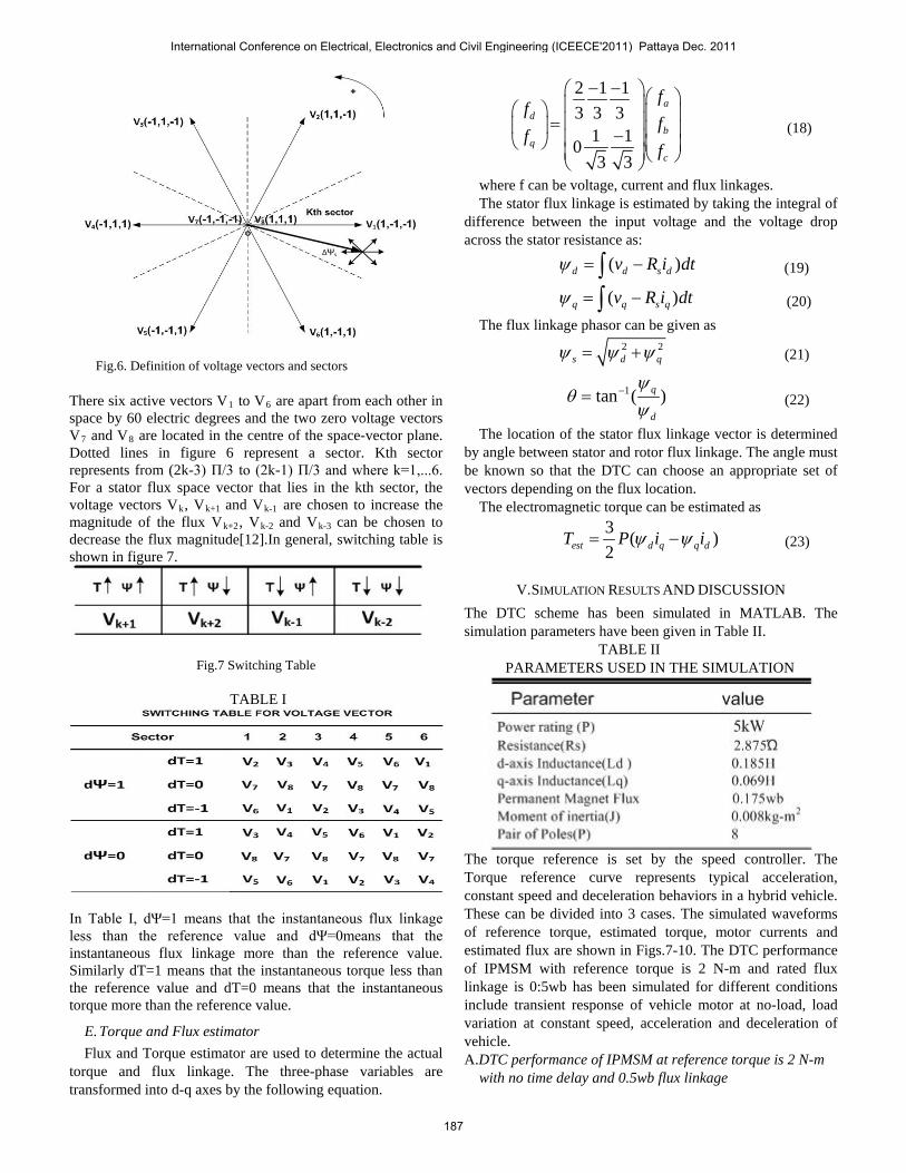
Fig.6. Definition of voltage vectors and sectors
There six active vectors V1 to V6 are apart from each other in space by 60 electric degrees and the two zero voltage vectors V7 and V8 are located in the centre of the space-vector plane. Dotted lines in figure 6 represent a sector. Kth sector represents from (2k-3) Π/3 to (2k-1) Π/3 and where k=1,...6. For a stator flux space vector that lies in the kth sector, the voltage vectors Vk, Vk+1 and Vk-1 are chosen to increase the magnitude of the flux Vk+2, Vk-2 and Vk-3 can be chosen to decrease the flux magnitude[12].In general, switching table is shown in figure 7.
Fig.7 Switching Table
TABLE I
In Table I, dΨ=1 means that the instantaneous flux linkage less than the reference value and dΨ=0means that the instantaneous flux linkage more than the reference value. Similarly dT=1 means that the instantaneous torque less than the reference value and dT=0 means that the instantaneous torque more than the reference value.
E. Torque and Flux estimator Flux and Torque estimator are used to determine the actual
torque and flux linkage. The three-phase variables are transformed into d-q axes by the following equation.
2 1 1
3 3 31 1
03 3
ad
bq
c
ff
ff
f
− − = −
(18)
where f can be voltage, current and flux linkages. The stator flux linkage is estimated by taking the integral of
difference between the input voltage and the voltage drop across the stator resistance as:
( )d d s dv R i dtψ = −∫ (19)
( )q q s qv R i dtψ = −∫ (20)
The flux linkage phasor can be given as
2 2
s d qψ ψ ψ= + (21)
1tan ( )q
d
ψθ
ψ−= (22)
The location of the stator flux linkage vector is determined by angle between stator and rotor flux linkage. The angle must be known so that the DTC can choose an appropriate set of vectors depending on the flux location.
The electromagnetic torque can be estimated as
3
( )2est d q q dT P i iψ ψ= − (23)
V. SIMULATION RESULTS AND DISCUSSION
The DTC scheme has been simulated in MATLAB. The simulation parameters have been given in Table II. TABLE II PARAMETERS USED IN THE SIMULATION
The torque reference is set by the speed controller. The Torque reference curve represents typical acceleration, constant speed and deceleration behaviors in a hybrid vehicle. These can be divided into 3 cases. The simulated waveforms of reference torque, estimated torque, motor currents and estimated flux are shown in Figs.7-10. The DTC performance of IPMSM with reference torque is 2 N-m and rated flux linkage is 0:5wb has been simulated for different conditions include transient response of vehicle motor at no-load, load variation at constant speed, acceleration and deceleration of vehicle. A.DTC performance of IPMSM at reference torque is 2 N-m with no time delay and 0.5wb flux linkage
International Conference on Electrical, Electronics and Civil Engineering (ICEECE'2011) Pattaya Dec. 2011
187

Torque waveform settled at 2 N-m in 0.2 sec and flux waveform settled at 0.5Wb.
Fig.7 The Waveform of Reference Torque, Developed Torque, Stator flux linkage, Stator Current of the IPMSM. Tref at 2 N-m. B. DTC performance of IPMSM at reference toque is 2N-m with time delay of 0.1 sec and 0.5wb flux linkage
Fig. 8 The Waveform of Reference Torque, Developed Torque, Stator flux linkage, Stator Current of the IPMSM. Tref at 2 N-m. C. DTC performance of IPMSM at reference toque is 2 N-m to -2 N-m and 0.5wb flux linkage
Fig. 9 The Waveform of Reference Torque, Developed Torque, Stator flux linkage, Stator Current of the IPMSM. Torque waveform settled at -2N-mto 2N-m with settling time 0.2 sec and flux waveform settled at 0.5Wb. Harmonics are present in the current waveform and it is settled between 40A to -40A .Figure10 shows that in torque waveform ripple
content varies between 1.8N-m to 2.2N-m. The flux ripple varies from 0.47wb to 0.53wb
Fig.10 The Waveform of Developed Torque, Stator flux linkage, Stator Current of the IPMSM in Steady State Condition.
REFERENCES [1] C. C. Chan, A. Bouscayrol and K. Chen;“Electric, hybrid, and fuel cell
vehicles: architectures and modeling,.”IEEE Tran. On Vehicular Technology, Vol. 59, No.2, pp.589-598, February 2010.
[2] A. Emadi, Y. J. Lee and K. Rajashekara.;“Power electronics and motor drives in electric, hybrid electric, and plug-in hybrid electricvehicles.”IEEE Tran. On Industrial Electronics ,Vol. 55, No.6,pp.2237-2245,June 2008.
[3] K. T. Chau, C. C. Chan and L. Chunhua,“ Overview of permanent magnet brushless drives for electric and hybrid electric vehicles.”IEEE Tran. On Industrial Electronics, Vol. 55, No.6, pp.2246-2257,June 2008.
[4] M. Zeraoulia, M. E. H. Benbouzid and D. Diallo,“ Electric motor drive selection issues for HEV propulsion systems: a comparative study ”IEEE Tran. On Industrial Electronics, Vol. 44, No.6, pp.17561764, November 2006.
[5] Chen, F. and Dunnigan, M.W.,“Sliding-mode torque and flux control of an induction machine” IEE Proc.-Electr. Power Appl, Vol. 150, pp.227-236, March 2003.
[6] Depenbrock, M.,“Direct self control for high dynamics performance of inverter feed AC machines” ETZArchiv,Vol. 7, pp.211-218,1985.
[7] Takahashi, I. Noguchi, T.,“A new quick response and high efficiency strategy of an induction motor ”Conf. Rec. IEEE-IAS Annual Meeting, pp.495-502,1985.
[8] Mehrdad Ehsani, Khwaja M. Rahman and Hamid A. Toliyat,“ Propulsion System Design of Electric and Hybrid Vehicles” IEEE transactions on industrial electronics,Vol 44 ,Feb1997.
[9] Bum-su Jun; Jung-hyo Lee; Taeck-kie Lee; Chung-yuen Won;“Control of IPMSM for Hybrid Electric Commercial Vehicle,” Vehicle Power and Propulsion Conference (VPPC), 2010 IEEE ,pp.1-4, 1-3 Sept. 2010.
[10] Peter Vas”Sensor less Vector and Direct Torque Control Oxford University Press 1998.
[11] Pillay, P.; Krishnan, R;,“ Modeling of permanent magnet motor drives,” Industrial Electronics, IEEE Transactions on,vol 35,no.4 pp.537-541,Nov.1988.
[12] G. Buja, D. Casadei, and G. Serra,“ Direct stator flux and torque control of an induction motor: Theoretical analysis and experimental results ”in Proc. IECON 98, 24th Ann. Conf. IEEE Ind. Electron.Soc,Vol.1,pp.50-64,1998.
[13] Grenier, D., L.-A. Dessaint, O. Akhrif, Y. Bonnassieux, and B LePioufle, “Experimental Nonlinear Torque Control of a Permanent Magnet Synchronous Motor Using Saliency.”IEEE Tran. On Industrial Electronics, Vol. 44, No.5, pp.680-687, October 1997.
[14] Chee Mun ONG”Dynamic Simulation of Electric Machinery”,Prentice Hall 1998.
[15] N. R. N. Idris, A.H. M. Yatim,“ Direct Torque Control of induction Machines with constant switching frequency and Reduced Torque Ripple” IEEE Tran. On Industrial Electronics, Vol.51, No.4, 2004.
International Conference on Electrical, Electronics and Civil Engineering (ICEECE'2011) Pattaya Dec. 2011
188


![Optimal Design for Cogging Torque Reduction of an …PD-A5-14]_804.pdf · Optimal Design for Cogging Torque Reduction of an IPMSM Using PSO with Anti-Submarine Operation Concept](https://img.pdfslide.net/doc/110x75/5b1557bd7f8b9ae7348be0ed/optimal-design-for-cogging-torque-reduction-of-an-pd-a5-14804pdf-optimal.jpg)