Embed Size (px)
Citation preview
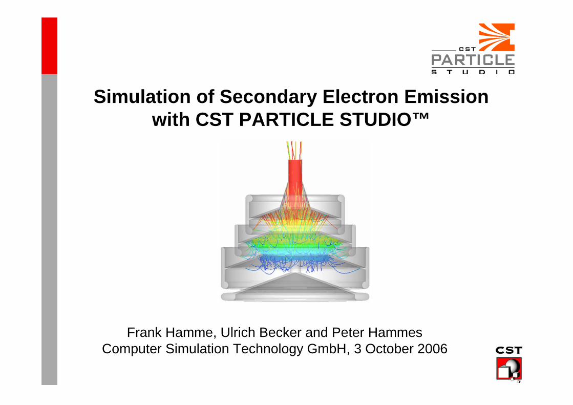
Simulation of Secondary Electron Emission with CST PARTICLE STUDIO™
Frank Hamme, Ulrich Becker and Peter HammesComputer Simulation Technology GmbH, 3 October 2006
ICAP 2006, 3 October 2006 2
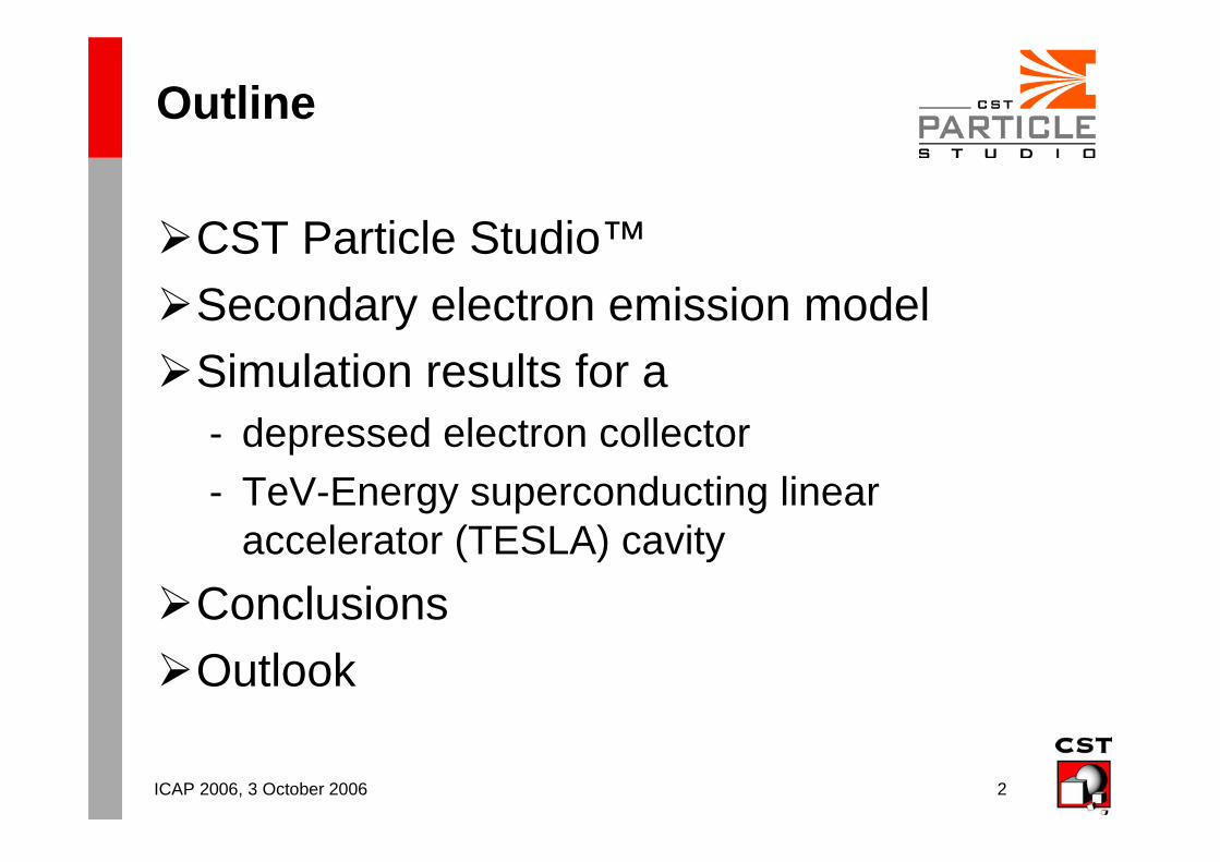
Outline
CST Particle Studio™
Secondary electron emission model
Simulation results for a- depressed electron collector
- TeV-Energy superconducting linear accelerator (TESLA) cavity
Conclusions
Outlook
ICAP 2006, 3 October 2006 3
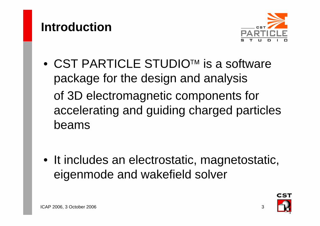
Introduction
• CST PARTICLE STUDIO™ is a software package for the design and analysis
of 3D electromagnetic components for accelerating and guiding charged particles beams
• It includes an electrostatic, magnetostatic, eigenmode and wakefield solver
ICAP 2006, 3 October 2006 4
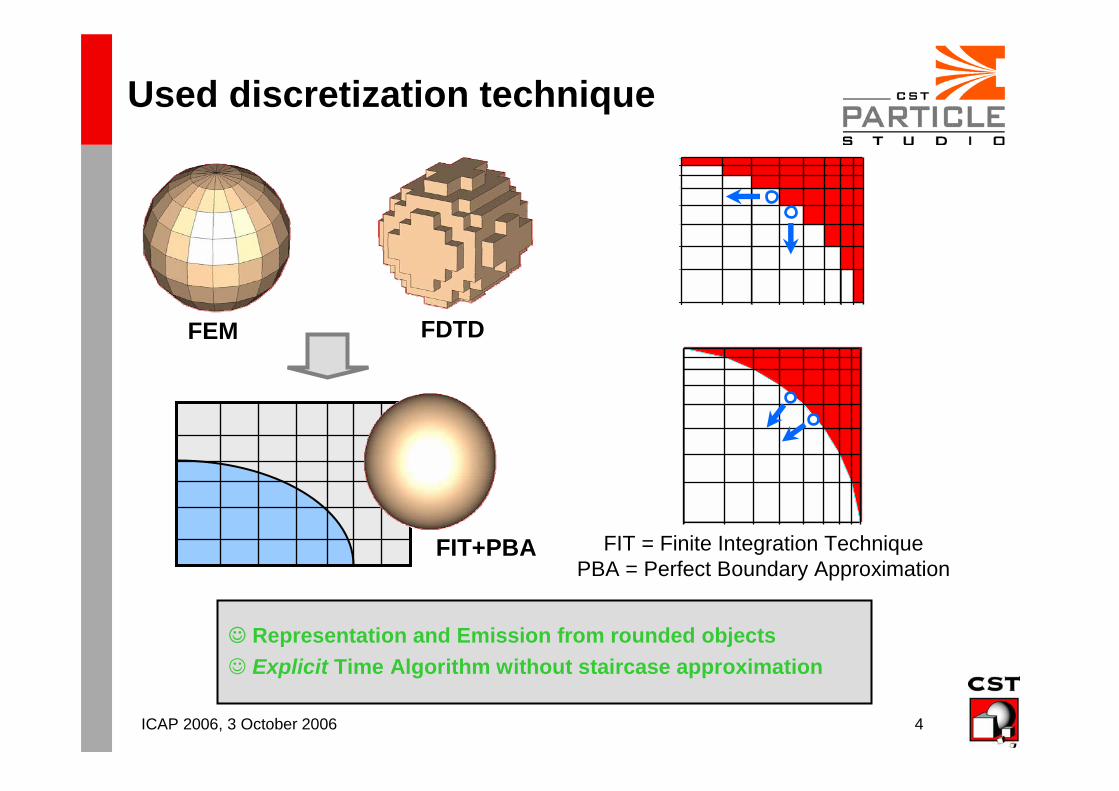
Used discretization technique
☺ Representation and Emission from rounded objects
☺ Explicit Time Algorithm without staircase approximation
FEM FDTD
FIT+PBA FIT = Finite Integration TechniquePBA = Perfect Boundary Approximation
ICAP 2006, 3 October 2006 5
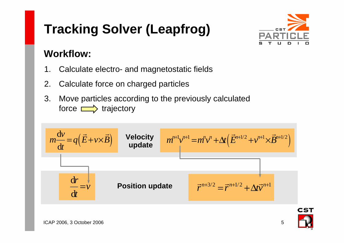
Tracking Solver (Leapfrog)
Workflow:
1. Calculate electro- and magnetostatic fields
2. Calculate force on charged particles
3. Move particles according to the previously calculatedforce trajectory
Velocity update( )d
d
vm q E v B
t= + ×
r r ( )1 1 1/2 1 1/2n n n n n n nm v m v t E v B+ + + + += +∆ + ×r r
Position updated
d
rv
t= 3/2 1/2 1n n nr r tv+ + += +∆r r r
ICAP 2006, 3 October 2006 6
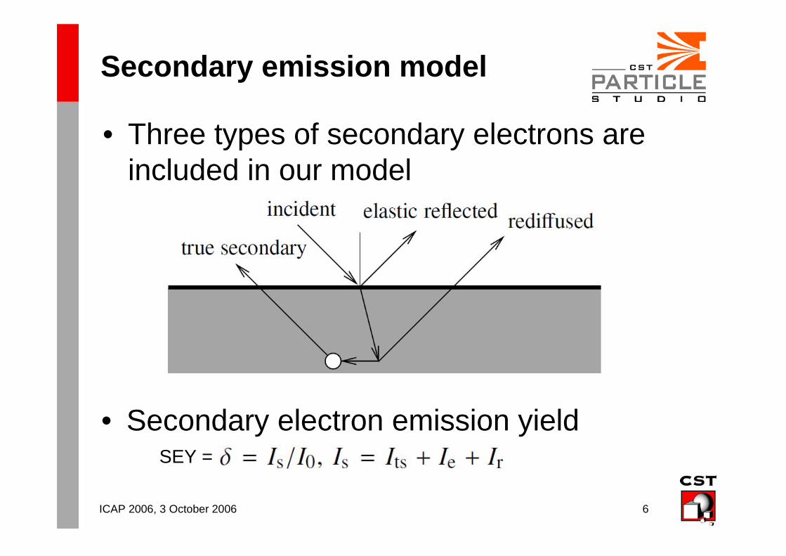
Secondary emission model
• Three types of secondary electrons are included in our model
• Secondary electron emission yieldSEY =
ICAP 2006, 3 October 2006 7
Secondary Emission Model
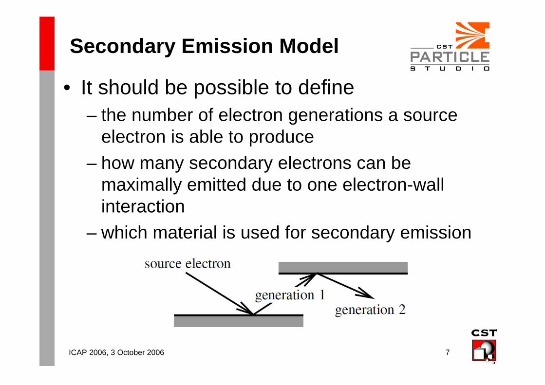
• It should be possible to define– the number of electron generations a source
electron is able to produce
– how many secondary electrons can be maximally emitted due to one electron-wall interaction
– which material is used for secondary emission
ICAP 2006, 3 October 2006 8
SEE – A Probabilistic Model
• Requirements for the model we need– material based, energy and angle dependent
– probabilistic model
– fulfillment of basic conservation laws, e.g. that the energy of emitted electrons should not exceed the energy of the primary electron
Our implementation is based on a model developed by Furman and Pivi
Probabilistic model for the simulation of secondary electron emission, Physical Review Special Topics, Accelerators and Beams, Volume 5, 2002
ICAP 2006, 3 October 2006 9
SEE Model – Basics
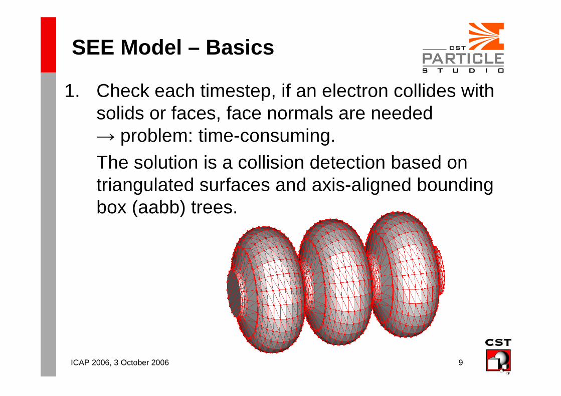
1. Check each timestep, if an electron collides with solids or faces, face normals are needed→ problem: time-consuming.
The solution is a collision detection based on triangulated surfaces and axis-aligned bounding box (aabb) trees.
ICAP 2006, 3 October 2006 10
SEE Model – Basics
2. If an electron collides, generate random numbers to get the kind of emission (elastic, etc.) and the number of new secondary electrons.
ICAP 2006, 3 October 2006 11
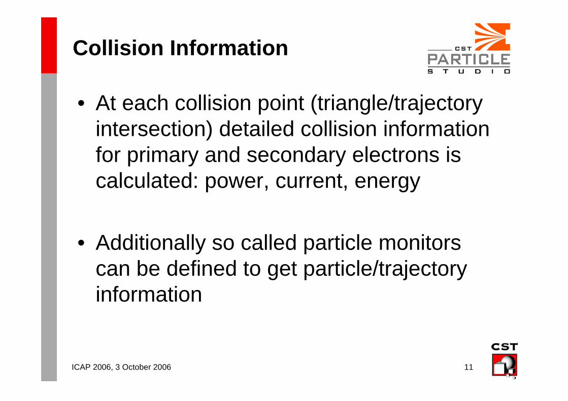
Collision Information
• At each collision point (triangle/trajectory intersection) detailed collision information for primary and secondary electrons is calculated: power, current, energy
• Additionally so called particle monitors can be defined to get particle/trajectory information
ICAP 2006, 3 October 2006 12
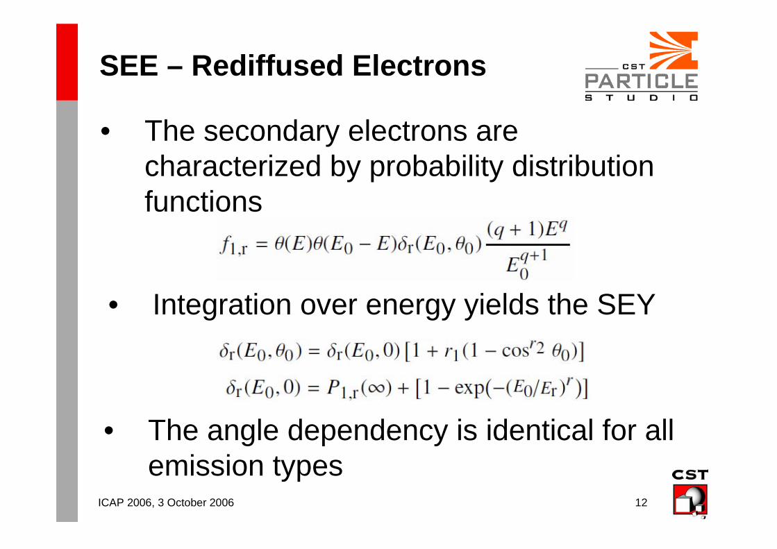
SEE – Rediffused Electrons
• The secondary electrons are characterized by probability distribution functions
• Integration over energy yields the SEY
• The angle dependency is identical for all emission types
ICAP 2006, 3 October 2006 13
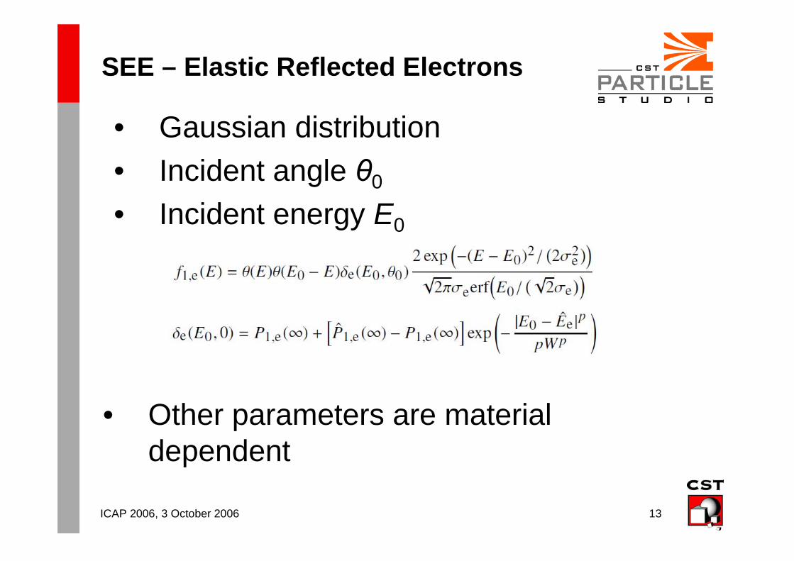
SEE – Elastic Reflected Electrons
• Gaussian distribution
• Incident angle θ0
• Incident energy E0
• Other parameters are material dependent
ICAP 2006, 3 October 2006 14
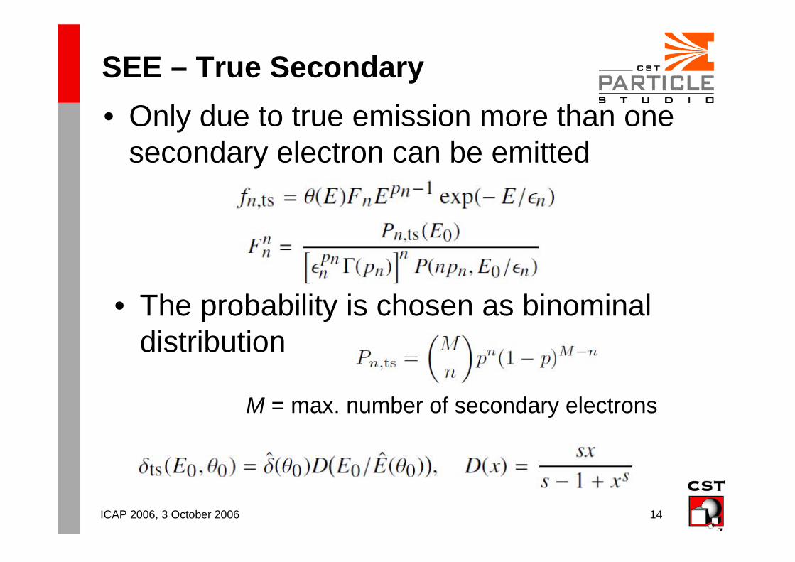
SEE – True Secondary
• The probability is chosen as binominal distribution
M = max. number of secondary electrons
• Only due to true emission more than one secondary electron can be emitted
ICAP 2006, 3 October 2006 15
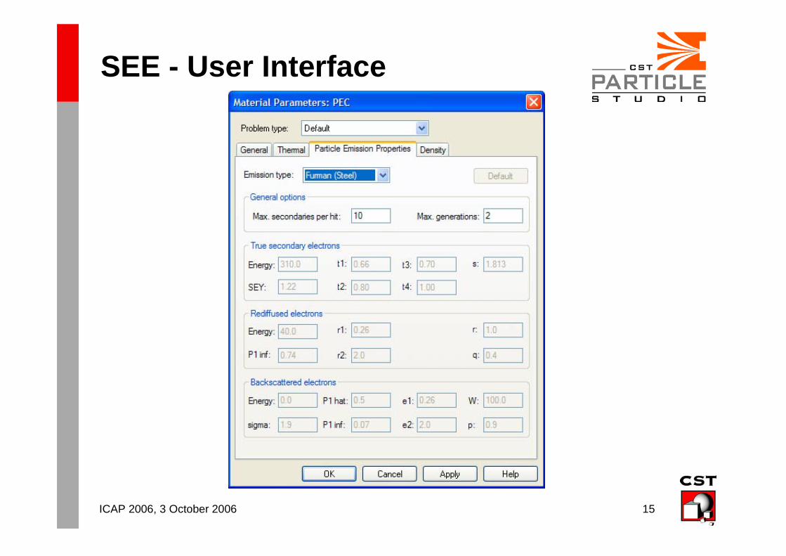
SEE - User Interface
ICAP 2006, 3 October 2006 16
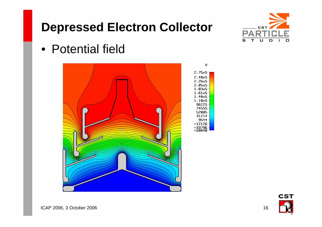
Depressed Electron Collector
• Potential field
ICAP 2006, 3 October 2006 17
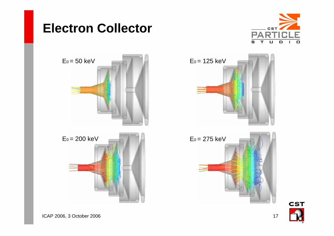
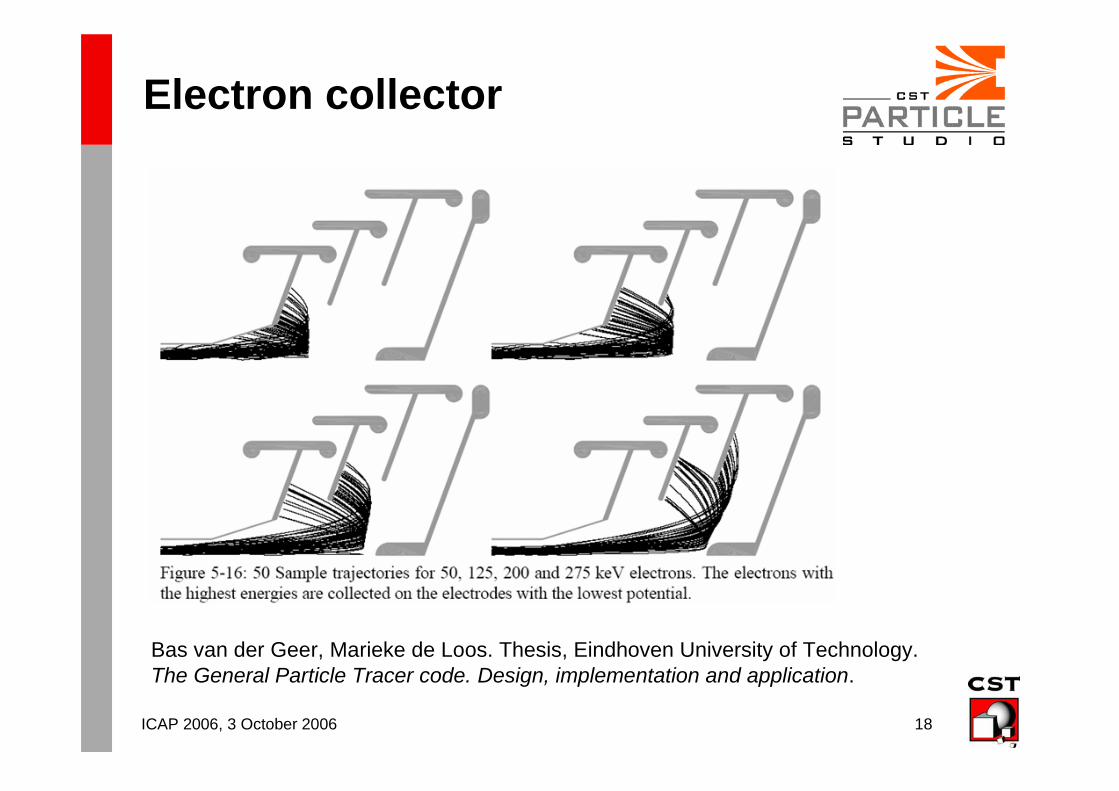
Electron Collector
E0 = 50 keV
E0 = 200 keV E0 = 275 keV
E0 = 125 keV
ICAP 2006, 3 October 2006 18
Electron collector
Bas van der Geer, Marieke de Loos. Thesis, Eindhoven University of Technology. The General Particle Tracer code. Design, implementation and application.
ICAP 2006, 3 October 2006 19
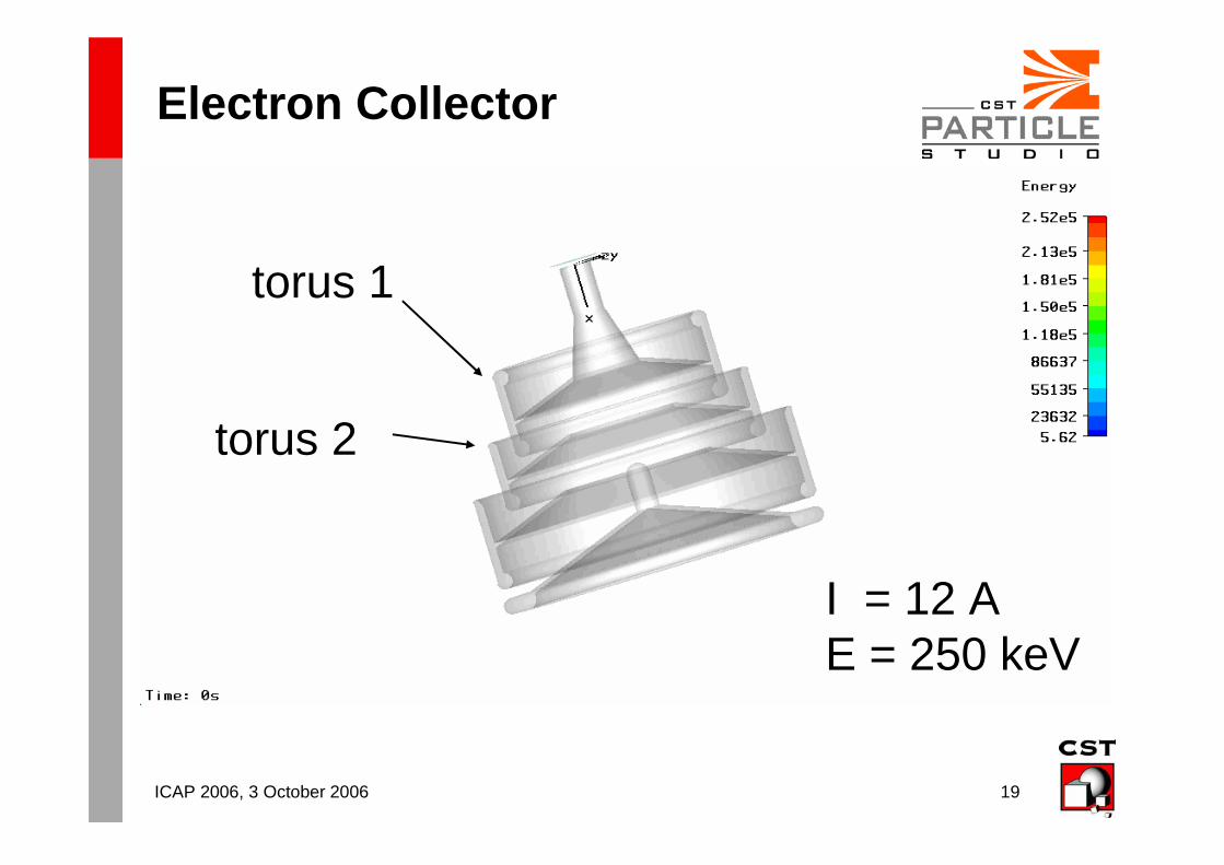
Electron Collector
I = 12 AE = 250 keV
torus 2
torus 1
ICAP 2006, 3 October 2006 20
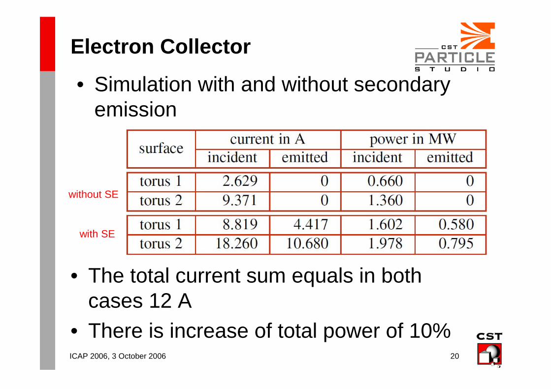
Electron Collector
• The total current sum equals in both cases 12 A
• There is increase of total power of 10%
• Simulation with and without secondary emission
with SE
without SE
ICAP 2006, 3 October 2006 21
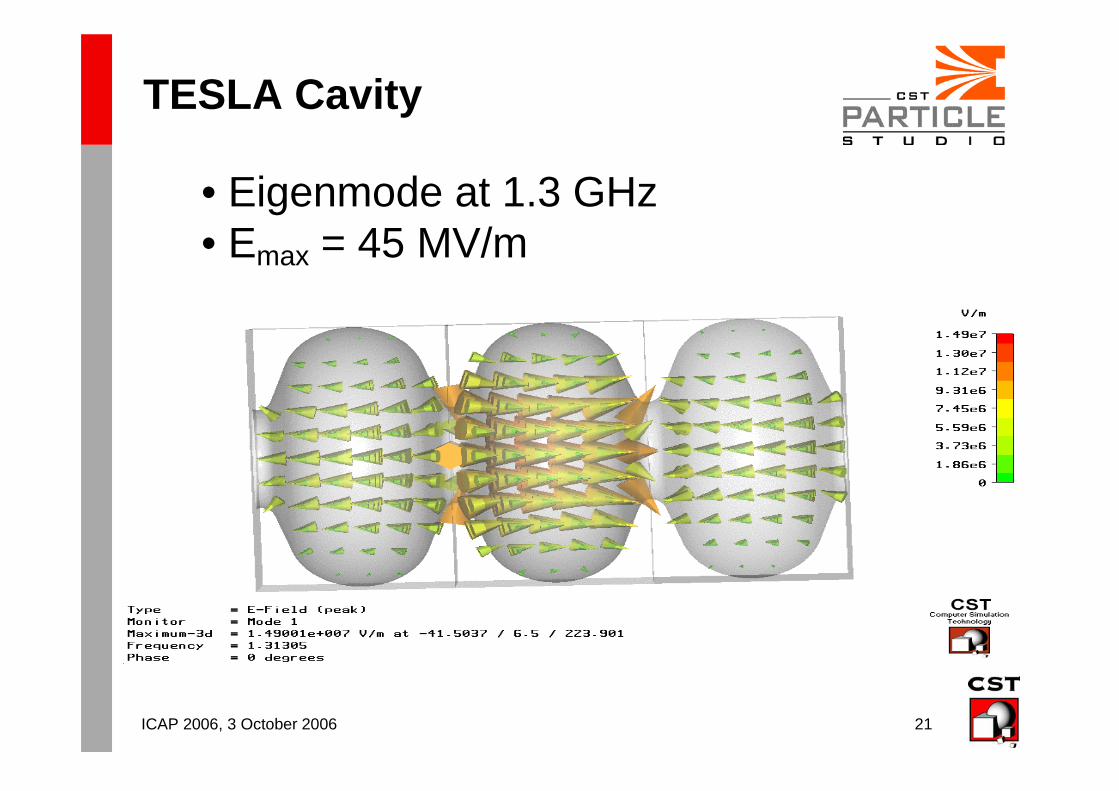
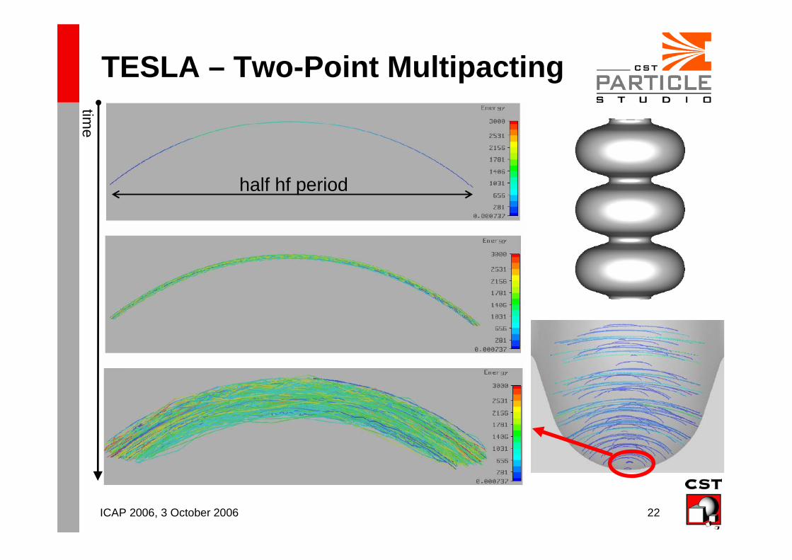
TESLA Cavity
• Eigenmode at 1.3 GHz• Emax = 45 MV/m
ICAP 2006, 3 October 2006 22
TESLA – Two-Point Multipacting
time
half hf period
ICAP 2006, 3 October 2006 23
Conclusions
• Furman SE model is implemented
• Very important are accurate input secondary emission material parameters
• The principals of two-point (and one-point) multipacting can be simulated with CST Particle Studio™
• Secondary electron emission is a heating mechanism for the depressed collector
ICAP 2006, 3 October 2006 24
Outlook
• Post processing analysis of the secondary emission heating with a thermal solver
• More material data to get better secondary emission simulation results
ICAP 2006, 3 October 2006 25
Thank you !