Embed Size (px)
Citation preview
SINGLE PHASE SINGLE STAGE HIGH DC VOLTAGE MULTIPLIER
CONVERTER
NOR AZIRA BINTI RAMLI
This report is submitted in partial fulfillment of the requirements for award of Bachelor
o f Electronic Engineering (Industrial Electronics) With Honours
Faculty of Electronic and Computer Engineering
Universiti Teknikal Malaysia Melaka
MAY 2008
UNIVERSTI TEKNIKAL MALAYSIA MELAKA FAKULTI KENRUTERAAN ELEKTRONIK DAN KEJURUTERAAN KOMPUTER
I u
BORANG PENGESAHAN STATUS LAPORAN PROJEK SARTANA MUDA II
Tajuk Projek : Single Phase Single Stage High DC Voltage Multiplier Converter
Sesi Pengajian : 200712008
Saya NOR AZIRA BMTI RAMLI mengaku membenarkan Laporan Projek Sarjana Muda ini di
sirnpan di PerpWakaan dengan syarat-syarat kegunaan seperti berikut:
1. Laporan adalah halanilik Universiti Teknikal Malaysia Melaka.
2. Perpustakaan dibenarkan membuat salinan untuk tujuan pengajian sahaja.
3. Perpustakaan dibenarkan membuat salinan laporan ini sebagai bahan pertukaran antara institusi
pengajian tinggi.
4. Sila tandakan ( 4 ) :
(Mengandungi maklumat yang berdarjah keselarnatan atau SULITL kepentingan Malaysia seperti yang tennaktub di dalarn AKTA
RAHSIA RASMI 1972)
TERHAD* (Mengandungi maklurnat terhad yang telah ditentukan oleh organisasilbadan di mana penyelidikan dijalankan)
TIDAK TERHAD
FKEKK), Alamat Tetap: BATU 24 '/s KUALA SUNGGA, Univemiti TMnikal Maby* b l a k a (UTeM),
KG. TEBONG, 76460 ALOR GAJAH, -rung bsrkund 1200,
MELAKA. Ayer m h , 7 5 4 9 Melekr
Tarikh: 9 MAY 2008 Tarikh: MAY 2008

"I hereby declare that this report is the result of my own work except for quotes as
cited in the references."
Signature :
Author : NOR AZIRA BMTI RAMLI
Date : 9h MAY 2008
"I hereby declare that I have read this report and in my opinion this report is
sufficient in terms of the scope and quality for the award of Bachelor of Electronic
Engineering (Industrial Electronics) With Honours."
ZULKASNAIN B ZAINUD~N
d a M q Komputer (FKEKK), Signature ?bh~nk8/ ~ a l a ~ 5 1 a &\aka ( U T ~ , ~ , ,
Karun Ber emiso is or's Name : MR. ZULKARNAIN B W Z & ~ %
Date : 9" MAY 2008

Especially for my beloved father and mother, my siblings and family.

ACKNOWLEDGEMENT
Alharndullillah, thanks to Allah because of his blessing, I manage to finish this
'Projek Sarjana Muda' in good condition and sharp on time. I also would like to take
this opportunity to give appreciation especially to my beloved father and mother
because of their support and understanding in helping me to finish this project, then
this appreciation goes to my honourable lecturer's which is Mr. Zulkarnain bin
Zainudin because of his guidelines and sharing some usefbl advice in order to help
me to give the best effort and commitment to finish this project. Finally, I would like
to thanks to all my lovely £tiends and other persons who always help and give
support to me along accomplished this PSM. Lots of thanks to them and hopefilly
Allah will pay their kindness.
ABSTRACT
This project paper proposed a single-phase single-stage high DC voltage
multiplier converter. The convertion of high DC voltage converter without a DC link
is involved. A high frequency transformer using ETD 59 ferrite core with ratio 1:l is
used as energy storage and also providing isolation. Cockroft-Walton circuit is
connected at secondary side of the transformer. AC input is controlled by IGBT
switch which the current flow in both directions of the transformer to fhlly utilize the
transformer core. The current flow is controlled by the IGBTs using PWM technique.
viii
Kertas kerja ini adalah cadangan untuk projek 'singlephase single-stage high DC
voltage multiplier converter'. Projek ini melibatkan proses penukaran pengubah
voltan tinggi arus terus, tanpa menggunakan talian m s terus. Litar ini menggunakan
pengubah berfiekuensi tinggi iaitu teras ferit ETD 59 dgn nisbah 1:l yang befingsi
untuk menyimpan tenaga di mana penebat juga turut disediakan. Litar 'Cockcroft
Walton' akan disambungkan pada bahagian sekunder tranformer. Suis IGBT dikawal
oleh arus ulang alik, dimana m s yang mengalir pada keduadua arah pada litar
transformer ini akan membuatkan teras pengubah berfUngsi sepenuhnya. IGBT
mengawal arus yang mengalir melalui teknik denyut lebar modulasi (pulse width
modulation).
CONTENT
CHAPTER TITLE
PROJECT TITLE
DECLARATION
DEDICATION
ACKNOWLEDGEMENT
ABSTRACT
ABSTRAK
CONTENTS
LIST OF FIGURES
LIST OF ABBREVIATION
LIST OF APPENDICES
I INTRODUCTION
1.1 Introduction of the Project
1.2 Objective of the Project
1.3 Problem Statement
1.4 Scope
1.5 Methodology
I1 LITERATURE REVIEW
PAGE
i
iii
v
vi
vii
viii
ix
xii
xiv
xv
2.1 Introduction
m METHODOLOGY
Introduction
Single Phase
Single Stage
Voltage Multiplier
Cockcroft Walton Multiplier
3.5.1 Operational Characteristics
3.5.2 The Full Wave Cockcroft Walton
3.5.3 Regulation and Ripple Calculation for
Full Wave Cockcroft Walton
Proposed Topology
Circuit Operation
3.7.1 Section 1
3.7.2 Section 2
3.7.3 Section 3
Switching Strategies
Ferrite Core Analysis
Simulation Measurements
Hardware Measurements
IV RESULTS AND DISCUSSION
4.1 Introduction
4.2 Simulation Results
4.2.1 The simulation by using MicroSim Eva1 8
4.2.2 The simulation by using Multisim 8
4.2.3 The simulation by using OrCAD Pspice
4.2.4 The simulation of main circuit by using
Multisim 6
4.2.5 The simulation of the comparator circuit by
using Multisim 6
4.2.5.1 The Simulation Results
4.3 Hardware 42
4.3.1 Design the circuit by using Protell 99 SE 43
4.3.2 Place the component on the Positive Board 46
4.3.3 Testing and Toubleshooting the Circuit 47
4.3.4 Observation of the Output 48
4.3.5 Observation of the Overall Circuit 49
V CONCLUSION AND SUGGESTION
5.1 Conclusion
5.2 Suggestion for Future Works

xii
LIST OF FIGURES
3.7.1
3.7.1.1
3.7.2.1
3.7.3.1
3.8.1
3.8.2
3.8.3 (a)
3.8.3 (b)
TITLE
Cockcroft Walton Multiplier circuit
Two stage of Cockcroft Walton Multiplier circuit
The output voltage of Cockcroft Walton Multiplier
The fillwave Cockcroft Walton circuit
System configuration of single phase single-stage high
DC converter
The circuit in three sections
Section 1
Section 2
Section 3
PWM using 'w' shape carrier signal
PWM generation using 'm' shape carrier signal
Fourier transforms of input supply current Multiple-pulse
PWM
Fourier transforms of input supply current Sinusoidal
PWM
The sine sawtooth wave
The PWM generated from the comparison between
triangular and sine wave
The comparator used to trigger the IGBTs
The multiple-pulse PWM
B-H curve
ETD59 half core
The single phase single-stage high DC converter circuit
PAGE
9
11
1 1
13
14
The circuit after remove the Cockcroft Walton circuit
The single phase single-stage high DC converter circuit
The single phase single-stage high DC converter circuit
The single phase single-stage high DC converter circuit
The comparator circuit
The comparator was compressed into subcomparator
circuit
The PWM signal input for IGBTs M1&M2 and M3&M4
The PWM signal input for IGBTs MA&MB
The design of the main circuit in the Protel99SE
The bottom overview of the main circuit
The bottom overview after grounding the circuit
The design of the adjustable sawtooth generator
The bottom overview of the adjustable sawtooth
generator circuit
The overview of the main circuit components
The overview of the adjustable saw tooth generator
circuit components
The overview of the comparator circuit components
Testing the adjustable sawtooth generator circuit
The input voltage of the adjustable sawtooth generator
circuit
The output of triangular wave that have distortion
The smooth triangular wave
The PWM signal from the comparator circuit
The overview of the overall circuit of the project
The overview of the main circuit
The overviem of the PWM generator circuit
The source input voltage for the main circuit
The output voltage from the main circuit
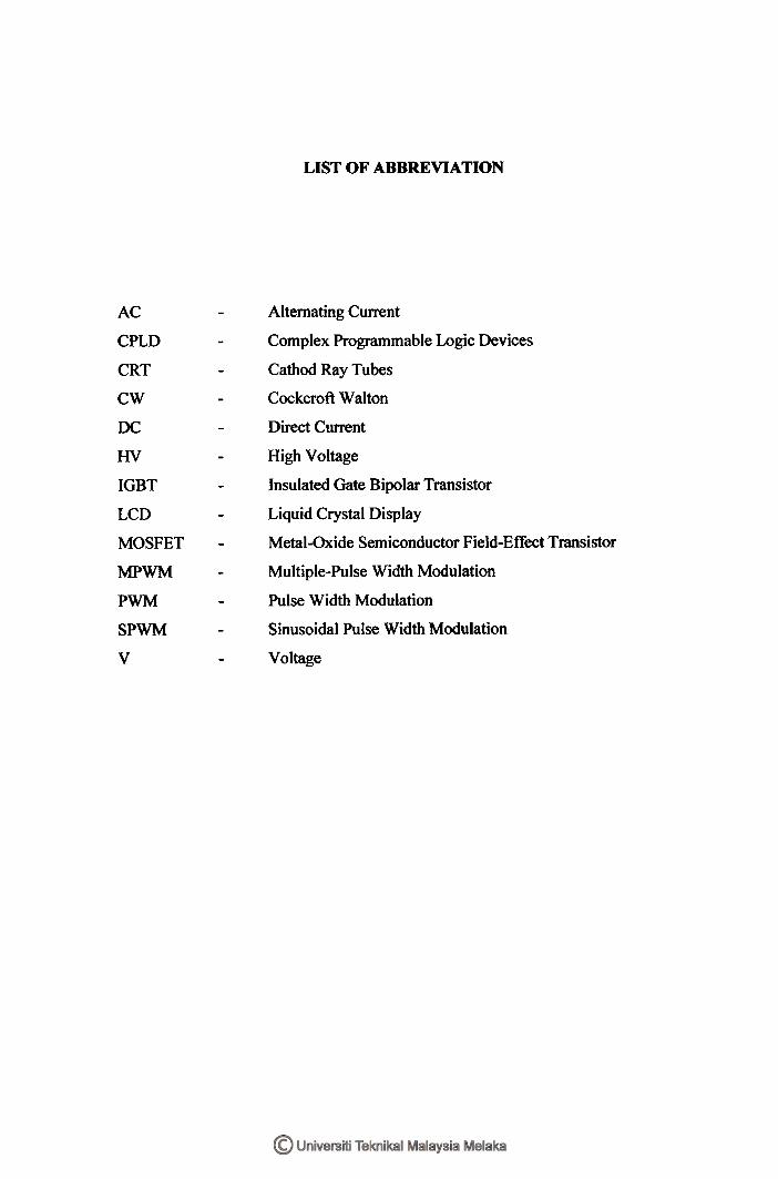
LIST OF ABBREVIATION
AC
CPLD
CRT
CW
DC
HV
IGBT
LCD
MOSFET
MPWM
PWM
SP WM
v
- Alternating Current
- Complex Programmable Logic Devices
- Cathod Ray Tubes
- Cockcroft Walton
- Direct Current
- High Voltage
- Insulated Gate Bipolar Transistor
- Liquid Crystal Display
- Metal-Oxide Semiconductor Field-Eff'ect Transistor
- Multiple-Pulse Width Modulation
- Pulse Width Modulation
- Sinusoidal Pulse Width Modulation
- Voltage

LIST OF APPENDICES
NO TITLE
A Datasheet BYW54 to BYW 56
B Datasheet BUP 3 14
C Datasheet RHRP30 120
PAGE
55
63
72
CHAPTER I
INTRODUCTION
1.1 Introduction of the Project
This project proposed about the single phase single-stage high Direct Current
(DC) voltage muliplier converter which is used to produce high voltage at low power. In
this project, a new method of controlling Cockcroft Walton Voltage Multiplier circuit
using a digital controller is presented. The digital controller is developed using analog
method where the comparator will be used to compare the triangular wave and the sine
wave (input signal). The proposed system utilizes a single phase Alternating Current
(AC) input supply. The power switching devices in the controlled bridge are controlled
by the multiple-pulse Pulse Width Modulation (PWM) switching technique so as to
minimize the low order harmonics present on the AC side of the converter system. A
low pass filter is incorporated in the circuit to filter out unwanted harmonics provide a
sinusoidal AC supply current.
1.2 Objective of the Project
The main objectives of this project are:
1. To design and simulate the circuit for the single-phase single-stage high DC
voltage multiplier converter by using analog method.
2. To build the prototype for the single-phase single-stage high DC voltage
multiplier converter circuit.
3. To analyze and compared the results between the simulation and prototype
results.
4. To generate higher output voltage compared to the input.
1 3 Problem Statement
There is no information about controlling the Cockroft Walton using digital
technique controller. So, in this project the conventional Cockroft Walton will be
controlled by six switches where the AC supply are chopped to high frequency AC
using PWM technique and coupled using high-frequency transformer. The analog
method will be used to develop the PWM switching pattern.
1.4 Scope
This project will include the explaination of the single phase single stage high
DC voltage multiplier converter. Then, by using the Multisim, Pspice, Protell 99 SE and
other related software, the circuit will be design and simulate to ensure that the result
was almost same with the theoritical results. The prototype of the circuit will be built
and tested in order to make sure the circuit works properly. Finally, the comparisons
between the simulation and the experimental results and were observed.
1.5 Methodology
In this project, the understanding about the Cockcroft Walton voltage multilier is
needed.The conventional Cockcroft Walton (CW) connects AC supply directly to the
input of Cockcroft Walton voltage multiplier circuit.The CW controlled by using analog
method controller. Six switches of IGBT's will be used to chop the AC supply to high
frequency AC using PWM technique and coupled using high-fkequency transformer.
Comparator will be used to develop the PWM switching pattern.
CHAPTER I1
LITERATURE REVIEW
2.1 Introduction
The conventional technique of generating high DC voltage is by using multi-
stage or cascaded power conversion. The technique requires less sophisticated controller
to control its operation. However, due to the inherent characteristics of a multi-stage
system, it requires more components and more complex [I]. The present of lower order
of harmonics current injected back to the utility supply requires a large LC filter size to
minimize these effects. A low-power active filter can also be used to control the
harmonic current, but at some additional cost.
The high DC voltage can also be generated using a simple AC-DC topology,
which consists of a high ratio of a step-up transformer but requires a large size of
transformer. Although the topology is simple, the harmonic current generated on an AC
side is uncontrollable [2]. Single-stage power conversion is as topic that has been of
substantial interest to power electronics researchers in recent years, and numerous
converters have been proposed such as resonant converter, PWM converter etc. Most of
the single-stage AC-DC converter using a full bridge diode rectifier and a smoothing
inductance (DC-link) to maintain the ripple free current before it fed to the boost

converter. Again a bulky inductance is used. There is also single-stage converter without
a DC-link which is very attractive because they have very high input power factor but
unfortunately it is not suitable for all application because of some drawback [3].
Cockcroft-Walton (CW) voltage multiplier or cascaded rectifier is a well known
topology and have been widely used in many high-voltage low-power industrial
applications where a low cost, compact system is required [4]. Conventional CW
connects AC supply directly to the input of CW voltage multiplier circuit. There is no
papers wrote about controlling the CW using digital technique controller. In this paper,
the conventional CW will be controlled by six switches where the AC supply is chopped
to high frequency AC using PWM technique and coupled using high-frequency
transformer. Comparator is used to develop the PWM switching pattern.
PWM is a well-known wave shaping technique in power electronics converter
system. It has a wide range of applications that create interests in many researches in this
area. It has been used in all types of converters such as AC-DC, AC-AC, DC-AC, and
DC-DC various schemes of PWM have been reported. Some schemes are produced for a
specific converter topology and not suitable for others. In general, most of the research
is focused on optimizing the PWM switching pattern. The PWM was designed to reduce
the low order harmonics present in the system due to the switching and also to reduce
the switching stress imposes on the power switching devices [5].
Most PWM is generated by comparing a modulating signal with a triangular
carrier signal. However, the modulating signal may come in various shapes to suit the
converter topology, such as sine wave and constant DC. A sinusoidal modulating signal
is used for PWM in DC-AC converter where it is used to produce output AC voltage
with less low order of harmonics components, thus small size of LC filter is adequate.
However, a constant DC voltage as a modulating signal is used for PWM in AC-DC
converter to shape the input AC current to be close to sinusoidal with small LC filter and
having unity power factor [6] . These two popular PWM patterns are applied to the

converter as well as the other two modified PWM to investigate the performance of the
converter.
CHAPTER III
METHODOLOGY
3.1 Introduction
In this chapter, the explanation of the methodology of the project will be
discussed in details. Basically, this project needs more understanding about the
Cockcroft Walton voltage multiplier and the PWM switching pattern that used to trigger
the IGBT. However, the important part is the understanding about the project title,
which is about single phase single stage high dc voltage multiplier converter where the
overall information about the project needs to be understood. So, this chapter will
explain in detail about the title definition; proposed topology, circuit operation,
simulation, hardware measurement and others.
3.2 Single Phase
In electrical engineering, single-phase electric power refers to the distribution of
electric power using a system in which all the voltages of the supply vary in unison.
Single-phase distribution is used when loads are mostly lighting and heating, with few
large electric motors. The generation of AC electric power is commonly three phases, in
which the waveforms of three supply conductors are offset from one another by 120".
Standard frequencies of single-phase power systems are either 50 or 60 Hz.
A single-phase load may be powered from a three-phase distribution system
either by connection between a phase and neutral [I20 V or 220 V], or by connecting the
load between two phases [I20 V and 120 V, the total being 240 V or 220 V and 220 V,
the total being 440 V]. The load device must be designed for the voltage in each
case.For example, in places using a 415 volt 3 phase system; the phase-to-neutral
voltage is 240 volts, allowing lighting to be connected phase-to ground and motors to be
connected to all three phases.
In North America, a typical three-phase system will have 208 volts between the
phases and 120 volts between phase and ground. If heating equipment designed for the
240-volt three-wire single phase system is connected to two phases of a 208 volt supply,
it will only produce 75% of its rated heating effect. Single-phase motors may have taps
to allow their use on either 208 V or 240 V supplies.
On higher voltage systems (kilovolts) where a single phase transformer is in use
to supply a low voltage system the method of splitting seems to vary by country. In
North America the primary of the step-down transformer is wired across a single high
voltage feed wire and ground, at least for smaller supplies (see photo of transformer on
right). In Britain the step-down primary is wired phase-phase. No arrangement of
transformers can convert a single-phase load into a balanced load on a polyphase
system.
3.3 Single Stage
A single stage single switch ACDC converter is an integration of input current
shaper and a DCIDC cell with a shared controller and one active switch. The converter is
applicable for digital input power supply with high input power factor and tight output
voltage regulation. The focus of the topology is to reduce the DC bus voltage at light
load without compromising with input power factor and voltage regulation. The concept
behind this topology is direct power transfer scheme. Using special configuration of
DCDC cell does reduction of DC bus voltage and DCDC cell works on the principle of
series charging and parallel discharging. The power output of this converter can go up to
200W.
3.4 Voltage Multiplier
A voltage multiplier is an electrical circuit that converts AC electrical power
from a lower voltage to a higher DC voltage by means of capacitors and diodes
combined into a network. Voltage multipliers can be used to generate bias voltages of a
few volts or tens of volts or millions of volts for purposes such as high-energy physics
experiments and lightning safety testing.
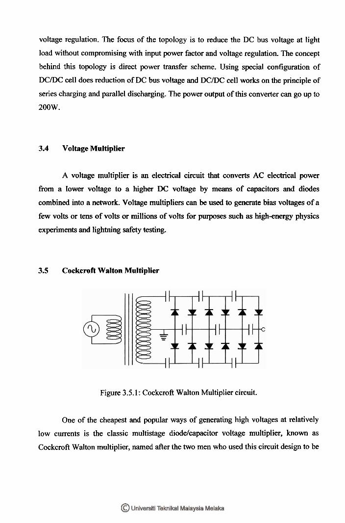
3.5 Cockcroft Walton Multiplier
Figure 3.5.1 : Cockcroft Walton Multiplier circuit.
One of the cheapest and popular ways of generating high voltages at relatively
low currents is the classic multistage diodelcapacitor voltage multiplier, known as
Cockcroft Walton multiplier, named after the two men who used this circuit design to be