Embed Size (px)
Citation preview
SIP-DECT Site Survey KitUSER GUIDE
NOTICE
The information contained in this document is believed to be accurate in all respects but is not warranted by Mitel Networks™ Corporation (MITEL®). The information is subject to change without notice and should not be construed in any way as a commitment by Mitel or any of its affiliates or subsidiaries. Mitel and its affiliates and subsidiaries assume no responsibility for any errors or omissions in this document. Revisions of this document or new editions of it may be issued to incorporate such changes.
No part of this document can be reproduced or transmitted in any form or by any means - electronic or mechanical - for any purpose without written permission from Mitel Networks Corporation.
Trademarks
Mitel is a trademark of Mitel Networks Corporation.
Windows is a trademark of Microsoft Corporation.
Other product names mentioned in this document may be trademarks of their respective companies and are hereby acknowledged.
SIP-DECT Site Survey Kit User GuideJuly 2015
®,™ Trademark of Mitel Networks Corporation© Copyright 2015, Mitel Networks Corporation
All rights reserved
Table of Contents
iii
USING THE SIP-DECT SITE SURVEY KIT
Safety Information . . . . . . . . . . . . . . . . . . . . . . . . . . . . . . . . . . . . . . . . . . . . . . . . . . . . . . . . . . . . . . . 3
Exclusion of Liability . . . . . . . . . . . . . . . . . . . . . . . . . . . . . . . . . . . . . . . . . . . . . . . . . . . . . . . . . . . 3
The SIP-DECT Site Survey Kit . . . . . . . . . . . . . . . . . . . . . . . . . . . . . . . . . . . . . . . . . . . . . . . . . . . . . 4
SIP-DECT Site Survey Kit Contents . . . . . . . . . . . . . . . . . . . . . . . . . . . . . . . . . . . . . . . . . . . . . . . 4
Setup . . . . . . . . . . . . . . . . . . . . . . . . . . . . . . . . . . . . . . . . . . . . . . . . . . . . . . . . . . . . . . . . . . . . . . . . . 5
DECT Base Station Set Up . . . . . . . . . . . . . . . . . . . . . . . . . . . . . . . . . . . . . . . . . . . . . . . . . . . . . . 5
Setting up the Mitel 650 DECT Phone for Measurement . . . . . . . . . . . . . . . . . . . . . . . . . . . . . . . 6
Preparing for the Next Measurement Session . . . . . . . . . . . . . . . . . . . . . . . . . . . . . . . . . . . . . . . 7
Charging the Powerpack . . . . . . . . . . . . . . . . . . . . . . . . . . . . . . . . . . . . . . . . . . . . . . . . . . . . . 7
Charging the Mitel 650 DECT Phone . . . . . . . . . . . . . . . . . . . . . . . . . . . . . . . . . . . . . . . . . . . . 7
Charging the iPod . . . . . . . . . . . . . . . . . . . . . . . . . . . . . . . . . . . . . . . . . . . . . . . . . . . . . . . . . . 7
Measurements . . . . . . . . . . . . . . . . . . . . . . . . . . . . . . . . . . . . . . . . . . . . . . . . . . . . . . . . . . . . . . . . . . 8
Display and Softkeys . . . . . . . . . . . . . . . . . . . . . . . . . . . . . . . . . . . . . . . . . . . . . . . . . . . . . . . . . . . 8
Measurements in Active Call State . . . . . . . . . . . . . . . . . . . . . . . . . . . . . . . . . . . . . . . . . . . . . . . . 9
Audio Quality Measurements . . . . . . . . . . . . . . . . . . . . . . . . . . . . . . . . . . . . . . . . . . . . . . . . . . . 10
Handover Menu . . . . . . . . . . . . . . . . . . . . . . . . . . . . . . . . . . . . . . . . . . . . . . . . . . . . . . . . . . . . . . 11
Planning and Site Survey. . . . . . . . . . . . . . . . . . . . . . . . . . . . . . . . . . . . . . . . . . . . . . . . . . . . . . . . . 12
Ascertaining Customer Requirements . . . . . . . . . . . . . . . . . . . . . . . . . . . . . . . . . . . . . . . . . . . . 12
Initial Determination of Base Station Locations . . . . . . . . . . . . . . . . . . . . . . . . . . . . . . . . . . . . . . 12
Optimum Positioning of the DECT Base Station . . . . . . . . . . . . . . . . . . . . . . . . . . . . . . . . . . . . . 13
DECT Base Station for Outdoor Supply . . . . . . . . . . . . . . . . . . . . . . . . . . . . . . . . . . . . . . . . . . . 14
DECT Base Station for Indoor Supply . . . . . . . . . . . . . . . . . . . . . . . . . . . . . . . . . . . . . . . . . . . . . 14
Preparing the Measurements . . . . . . . . . . . . . . . . . . . . . . . . . . . . . . . . . . . . . . . . . . . . . . . . . . . 15
Handover Overlap Areas: Base Station Synchronization . . . . . . . . . . . . . . . . . . . . . . . . . . . . . . 15
Traffic Density . . . . . . . . . . . . . . . . . . . . . . . . . . . . . . . . . . . . . . . . . . . . . . . . . . . . . . . . . . . . . . . 15
Hotspots . . . . . . . . . . . . . . . . . . . . . . . . . . . . . . . . . . . . . . . . . . . . . . . . . . . . . . . . . . . . . . . . . . . 16
Measuring Procedure . . . . . . . . . . . . . . . . . . . . . . . . . . . . . . . . . . . . . . . . . . . . . . . . . . . . . . . . . 16
TDM-Base Stations . . . . . . . . . . . . . . . . . . . . . . . . . . . . . . . . . . . . . . . . . . . . . . . . . . . . . . . . . . . 17
IP-Base Stations . . . . . . . . . . . . . . . . . . . . . . . . . . . . . . . . . . . . . . . . . . . . . . . . . . . . . . . . . . . . . 17
Basics . . . . . . . . . . . . . . . . . . . . . . . . . . . . . . . . . . . . . . . . . . . . . . . . . . . . . . . . . . . . . . . . . . . . . . . 19
Initial Considerations . . . . . . . . . . . . . . . . . . . . . . . . . . . . . . . . . . . . . . . . . . . . . . . . . . . . . . . . . . 19
Coverage Area . . . . . . . . . . . . . . . . . . . . . . . . . . . . . . . . . . . . . . . . . . . . . . . . . . . . . . . . . . . . . . 19
Coverage of a Radio System . . . . . . . . . . . . . . . . . . . . . . . . . . . . . . . . . . . . . . . . . . . . . . . . . . . 20
Radio Characteristic of a Base Station . . . . . . . . . . . . . . . . . . . . . . . . . . . . . . . . . . . . . . . . . . . . 20
High-Frequency Propagation Conditions . . . . . . . . . . . . . . . . . . . . . . . . . . . . . . . . . . . . . . . . . . 21
SIP-DECT Site Survey Kit User Guide
iv
Interference Factors . . . . . . . . . . . . . . . . . . . . . . . . . . . . . . . . . . . . . . . . . . . . . . . . . . . . . . . . . . 21
Reception Conditions . . . . . . . . . . . . . . . . . . . . . . . . . . . . . . . . . . . . . . . . . . . . . . . . . . . . . . . . . 23
Using External Antennas . . . . . . . . . . . . . . . . . . . . . . . . . . . . . . . . . . . . . . . . . . . . . . . . . . . . . . . 23
Fading Effect . . . . . . . . . . . . . . . . . . . . . . . . . . . . . . . . . . . . . . . . . . . . . . . . . . . . . . . . . . . . . . . . 24
APPENDIX A: TECHNICAL DATA
Technical specifications . . . . . . . . . . . . . . . . . . . . . . . . . . . . . . . . . . . . . . . . . . . . . . . . . . . . . . . . . . 26

USING THE SIP-DECT SITE
SURVEY KIT

SIP-DECT Site Survey Kit User Guide
2
Safety Information
3
SAFETY INFORMATION
Failure to observe this information can be hazardous and infringe existing laws. Please read this document before starting the testing and keep it for future reference. Make sure you always include the Manual when handing over the test kit to third parties.
• Do not use the test kit in areas subject to explosion hazards.
• Important information on using the batteries can be found in the Appendix.
• Do not place the equipment
- near sources of heat
- in direct sunlight
- near other electrical equipment
• Protect the equipment from the wet, dust, corrosive liquids and steam.
• Only connect approved accessories.
• Research has shown that in some cases, medical equipment can be affected by portable phones (DECT phones) when activated. Always observe the rules and regulations of the establishment concerned when using portable phones within medical facilities.
• Never
- open the equipment itself!
- touch the plug-in contacts with sharp and/or metallic objects!
• Only use a slightly damp cloth to clean the equipment.
EXCLUSION OF LIABILITY
• This product is manufactured in accordance with ISO 9001 quality criteria.
• This product and the user information supplied with it have been produced with the utmost care. The product's functions have been tested and approved after comprehensive conformity tests. Nonetheless errors cannot be entirely excluded. The warranty is limited to the replacement of defective hardware.
• The manufacturers shall not be liable for direct or indirect damage that may be caused by incorrect handling, improper use, or any other faulty behaviour on the part of a product. Liability for loss of profit shall be excluded in any case.
SIP-DECT Site Survey Kit User Guide
4
THE SIP-DECT SITE SURVEY KIT
SIP-DECT SITE SURVEY KIT CONTENTS
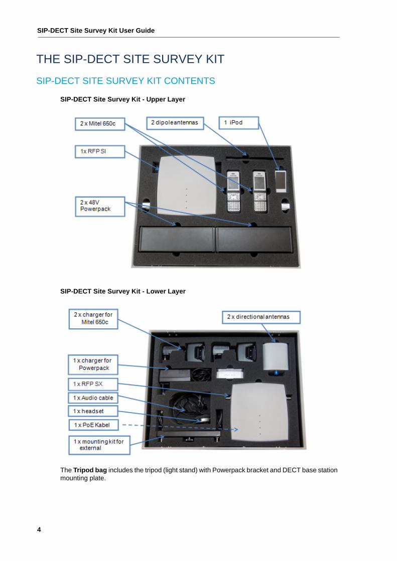
SIP-DECT Site Survey Kit - Upper Layer
SIP-DECT Site Survey Kit - Lower Layer
The Tripod bag includes the tripod (light stand) with Powerpack bracket and DECT base station mounting plate.
Setup
5
SETUP
In preparation for the measurement session and to optimize battery life time, all components should be fully charged. The Powerpack, Mitel 650 DECT phone and iPod should be switched off before being stored in the carrying case and for longer breaks between measurement sessions.
DECT BASE STATION SET UP
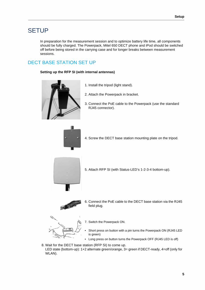
Setting up the RFP SI (with internal antennas)
1. Install the tripod (light stand).
2. Attach the Powerpack in bracket.
3. Connect the PoE cable to the Powerpack (use the standard RJ45 connector).
4. Screw the DECT base station mounting plate on the tripod.
5. Attach RFP SI (with Status-LED’s 1-2-3-4 bottom-up).
6. Connect the PoE cable to the DECT base station via the RJ45 field plug.
7. Switch the Powerpack ON.
• Short press on button with a pin turns the Powerpack ON (RJ45 LED is green)
• Long press on button turns the Powerpack OFF (RJ45 LED is off)
8. Wait for the DECT base station (RFP SI) to come up.LED state (bottom-up): 1+2 alternate green/orange, 3= green if DECT-ready, 4=off (only for WLAN).
SIP-DECT Site Survey Kit User Guide
6
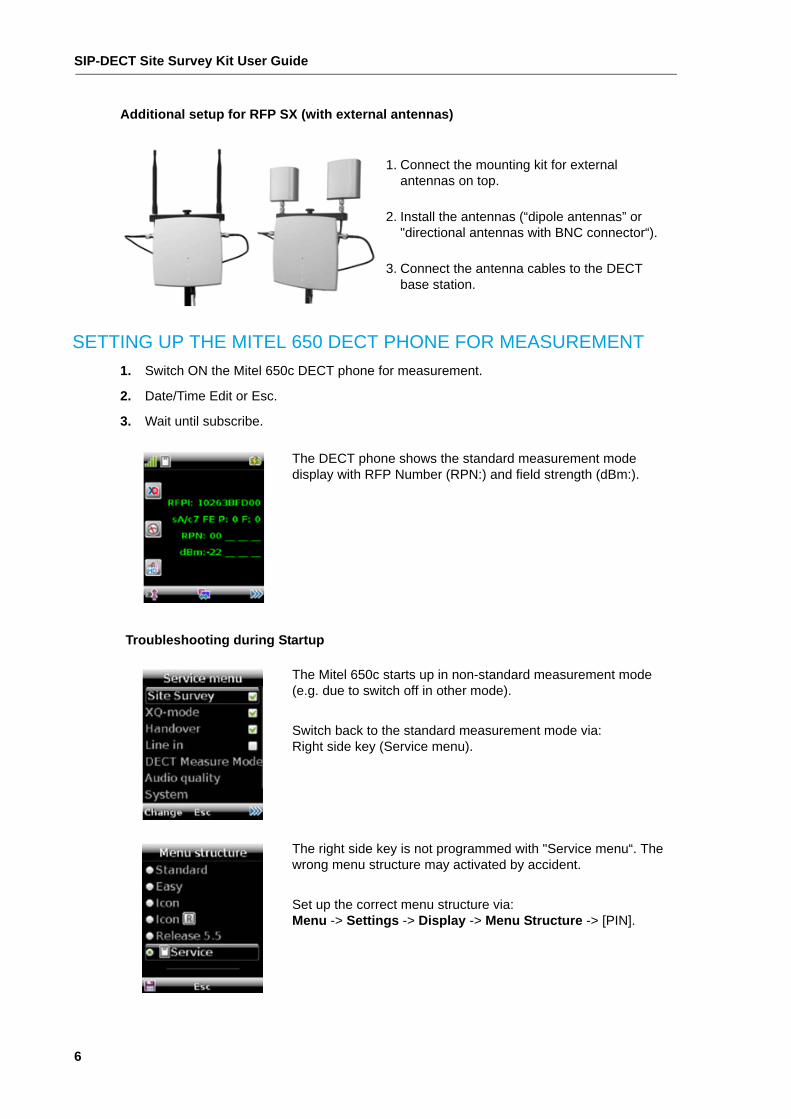
Additional setup for RFP SX (with external antennas)
SETTING UP THE MITEL 650 DECT PHONE FOR MEASUREMENT
1. Switch ON the Mitel 650c DECT phone for measurement.
2. Date/Time Edit or Esc.
3. Wait until subscribe.
1. Connect the mounting kit for external antennas on top.
2. Install the antennas (“dipole antennas” or "directional antennas with BNC connector“).
3. Connect the antenna cables to the DECT base station.
The DECT phone shows the standard measurement mode display with RFP Number (RPN:) and field strength (dBm:).
Troubleshooting during Startup
The Mitel 650c starts up in non-standard measurement mode (e.g. due to switch off in other mode).
Switch back to the standard measurement mode via:Right side key (Service menu).
The right side key is not programmed with "Service menu“. The wrong menu structure may activated by accident.
Set up the correct menu structure via:Menu -> Settings -> Display -> Menu Structure -> [PIN].
Setup
7
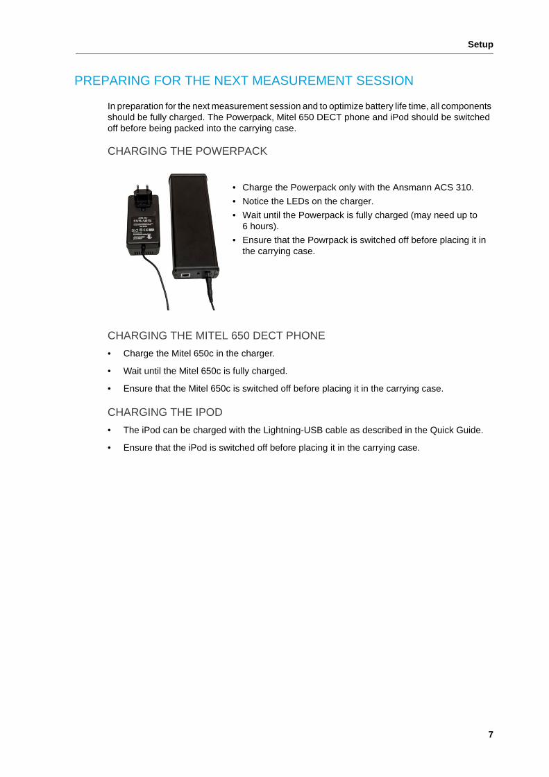
PREPARING FOR THE NEXT MEASUREMENT SESSION
In preparation for the next measurement session and to optimize battery life time, all components should be fully charged. The Powerpack, Mitel 650 DECT phone and iPod should be switched off before being packed into the carrying case.
CHARGING THE POWERPACK
CHARGING THE MITEL 650 DECT PHONE
• Charge the Mitel 650c in the charger.
• Wait until the Mitel 650c is fully charged.
• Ensure that the Mitel 650c is switched off before placing it in the carrying case.
CHARGING THE IPOD
• The iPod can be charged with the Lightning-USB cable as described in the Quick Guide.
• Ensure that the iPod is switched off before placing it in the carrying case.
• Charge the Powerpack only with the Ansmann ACS 310.
• Notice the LEDs on the charger.
• Wait until the Powerpack is fully charged (may need up to 6 hours).
• Ensure that the Powrpack is switched off before placing it in the carrying case.
SIP-DECT Site Survey Kit User Guide
8
MEASUREMENTS
For accurate results, all measurements must be made in active call state. A connection between the two DECT phones is established. The audio quality measurements support the site survey. By default, the DECT phones are subscribed to both RFP SI and RFP SX (DECT base stations) from the SIP-DECT Site Survey Kit. The DECT base stations are single cell with different PARK codes. Handover between RFP SI and SX is not possible.
DISPLAY AND SOFTKEYS
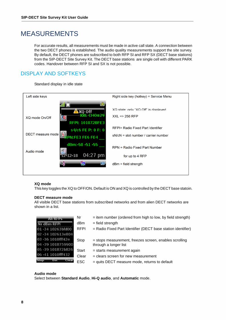
Standard display in idle state
XQ modeThis key toggles the XQ to OFF/ON. Default is ON and XQ is controlled by the DECT base statoin.
DECT measure modeAll visible DECT base stations from subscribed networks and from alien DECT networks are shown in a list.
Audio modeSelect between Standard Audio, Hi-Q audio, and Automatic mode.
Nr
dBm
RFPI
Stop
Start
Clear
ESC
= item number (ordered from high to low, by field strength)
= field strength
= Radio Fixed Part Identifier (DECT base station identifier)
= stops measurement, freezes screen, enables scrolling through a longer list
= starts measurement again
= clears screen for new measurement
= quits DECT measure mode, returns to default
Measurements
9
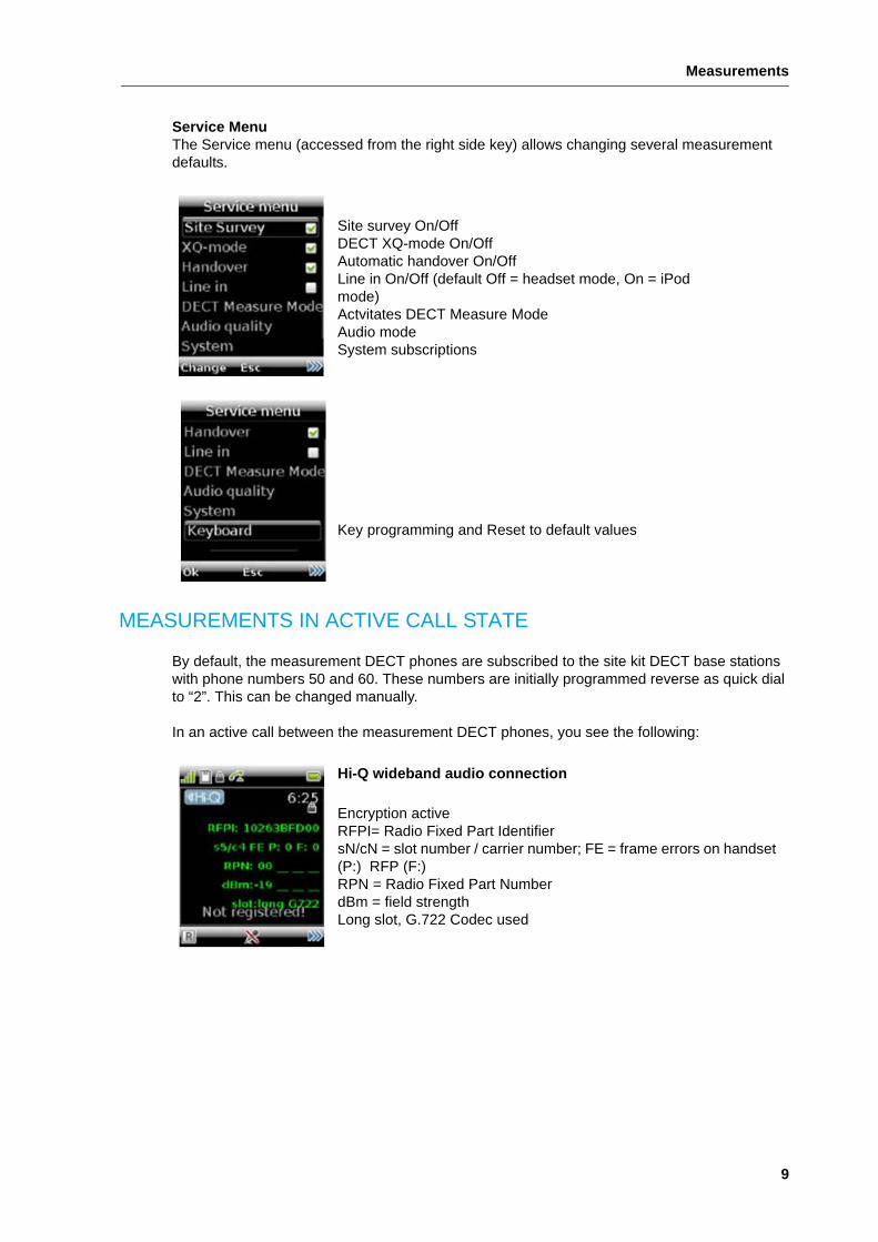
Service MenuThe Service menu (accessed from the right side key) allows changing several measurement defaults.
MEASUREMENTS IN ACTIVE CALL STATE
By default, the measurement DECT phones are subscribed to the site kit DECT base stations with phone numbers 50 and 60. These numbers are initially programmed reverse as quick dial to “2”. This can be changed manually.
In an active call between the measurement DECT phones, you see the following:
Site survey On/OffDECT XQ-mode On/OffAutomatic handover On/OffLine in On/Off (default Off = headset mode, On = iPod mode)Actvitates DECT Measure ModeAudio modeSystem subscriptions
Key programming and Reset to default values
Hi-Q wideband audio connection
Encryption activeRFPI= Radio Fixed Part IdentifiersN/cN = slot number / carrier number; FE = frame errors on handset (P:) RFP (F:)RPN = Radio Fixed Part NumberdBm = field strengthLong slot, G.722 Codec used
SIP-DECT Site Survey Kit User Guide
10
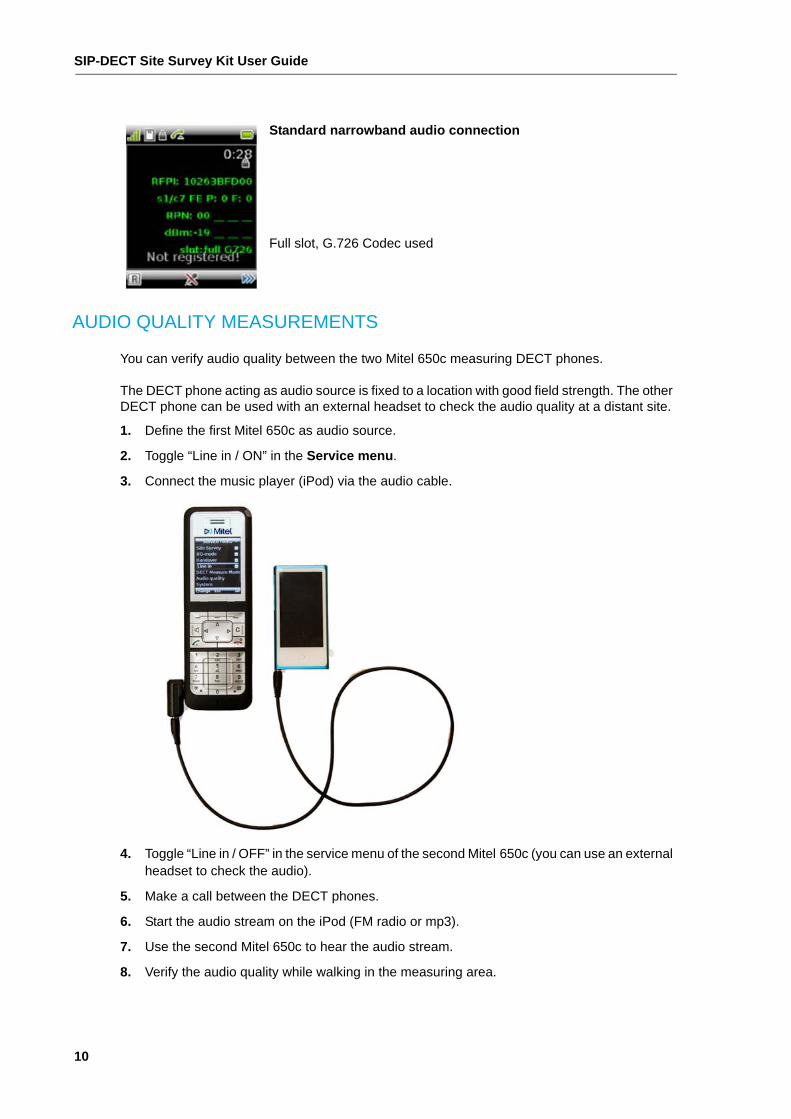
AUDIO QUALITY MEASUREMENTS
You can verify audio quality between the two Mitel 650c measuring DECT phones.
The DECT phone acting as audio source is fixed to a location with good field strength. The other DECT phone can be used with an external headset to check the audio quality at a distant site.
1. Define the first Mitel 650c as audio source.
2. Toggle “Line in / ON” in the Service menu.
3. Connect the music player (iPod) via the audio cable.
4. Toggle “Line in / OFF” in the service menu of the second Mitel 650c (you can use an external headset to check the audio).
5. Make a call between the DECT phones.
6. Start the audio stream on the iPod (FM radio or mp3).
7. Use the second Mitel 650c to hear the audio stream.
8. Verify the audio quality while walking in the measuring area.
Standard narrowband audio connection
Full slot, G.726 Codec used
Measurements
11
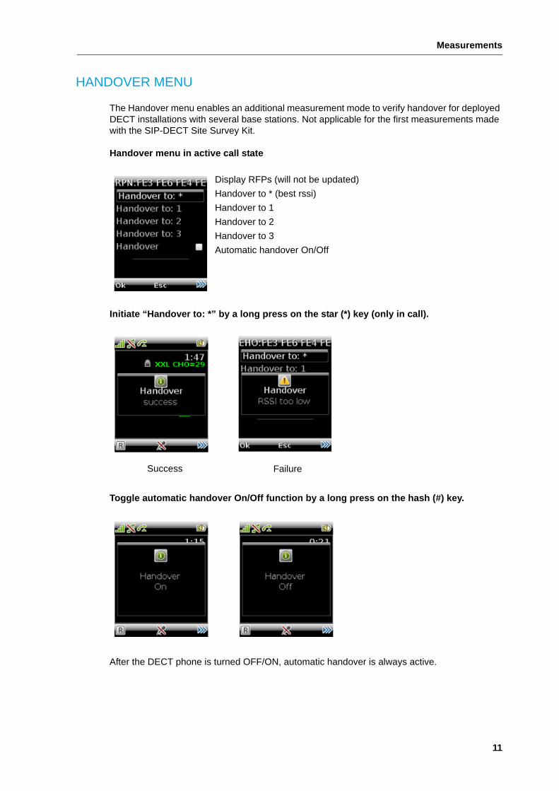
HANDOVER MENU
The Handover menu enables an additional measurement mode to verify handover for deployed DECT installations with several base stations. Not applicable for the first measurements made with the SIP-DECT Site Survey Kit.
Handover menu in active call state
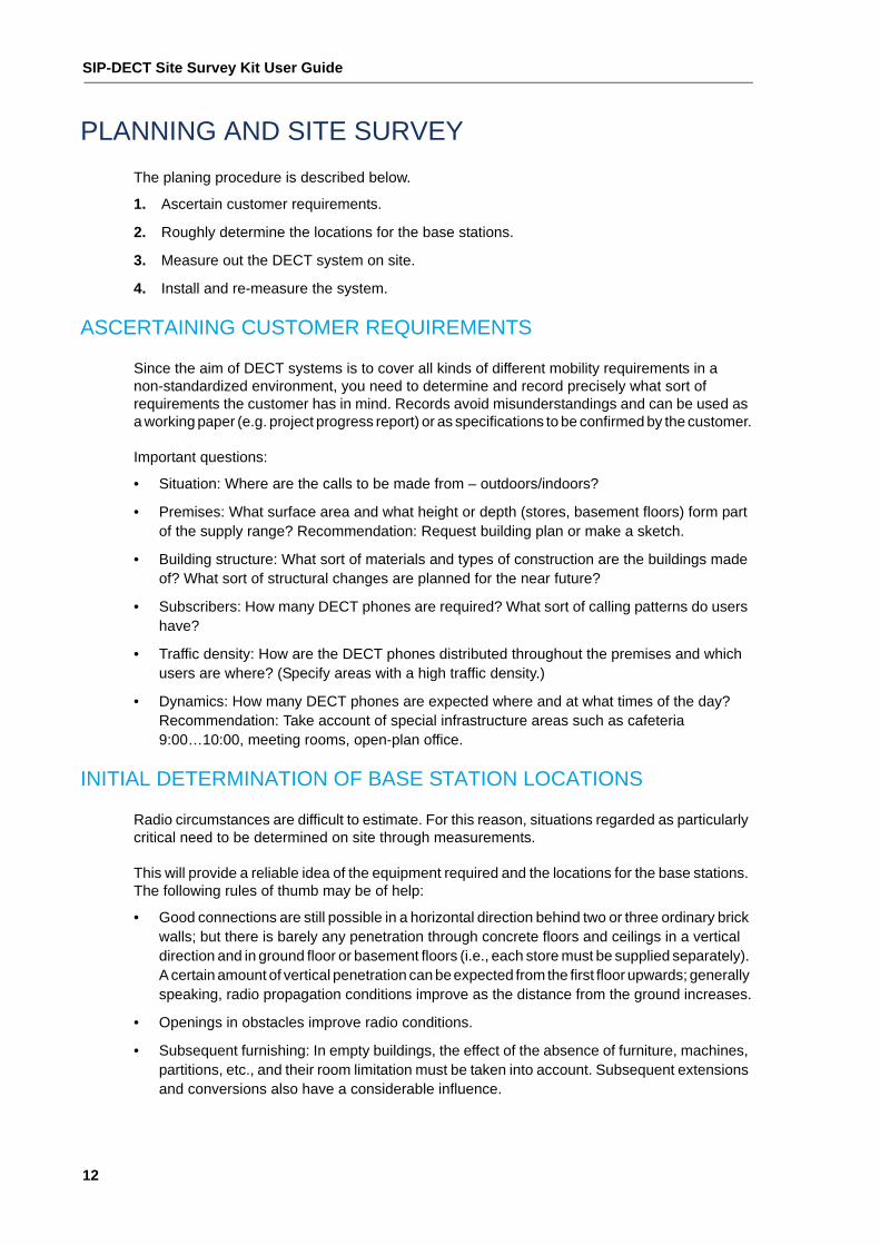
Initiate “Handover to: *” by a long press on the star (*) key (only in call).
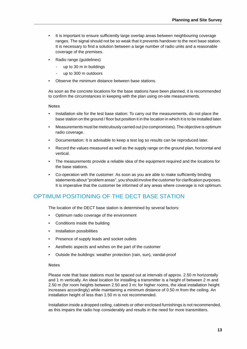
Toggle automatic handover On/Off function by a long press on the hash (#) key.
After the DECT phone is turned OFF/ON, automatic handover is always active.
Display RFPs (will not be updated)
Handover to * (best rssi)
Handover to 1
Handover to 2
Handover to 3
Automatic handover On/Off
Success Failure
SIP-DECT Site Survey Kit User Guide
12
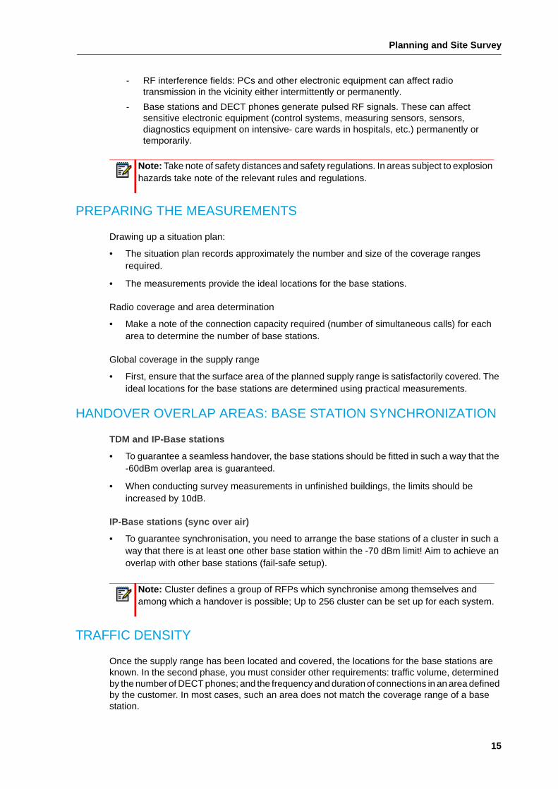
PLANNING AND SITE SURVEY
The planing procedure is described below.
1. Ascertain customer requirements.
2. Roughly determine the locations for the base stations.
3. Measure out the DECT system on site.
4. Install and re-measure the system.
ASCERTAINING CUSTOMER REQUIREMENTS
Since the aim of DECT systems is to cover all kinds of different mobility requirements in a non-standardized environment, you need to determine and record precisely what sort of requirements the customer has in mind. Records avoid misunderstandings and can be used as a working paper (e.g. project progress report) or as specifications to be confirmed by the customer.
Important questions:
• Situation: Where are the calls to be made from – outdoors/indoors?
• Premises: What surface area and what height or depth (stores, basement floors) form part of the supply range? Recommendation: Request building plan or make a sketch.
• Building structure: What sort of materials and types of construction are the buildings made of? What sort of structural changes are planned for the near future?
• Subscribers: How many DECT phones are required? What sort of calling patterns do users have?
• Traffic density: How are the DECT phones distributed throughout the premises and which users are where? (Specify areas with a high traffic density.)
• Dynamics: How many DECT phones are expected where and at what times of the day? Recommendation: Take account of special infrastructure areas such as cafeteria 9:00…10:00, meeting rooms, open-plan office.
INITIAL DETERMINATION OF BASE STATION LOCATIONS
Radio circumstances are difficult to estimate. For this reason, situations regarded as particularly critical need to be determined on site through measurements.
This will provide a reliable idea of the equipment required and the locations for the base stations. The following rules of thumb may be of help:
• Good connections are still possible in a horizontal direction behind two or three ordinary brick walls; but there is barely any penetration through concrete floors and ceilings in a vertical direction and in ground floor or basement floors (i.e., each store must be supplied separately). A certain amount of vertical penetration can be expected from the first floor upwards; generally speaking, radio propagation conditions improve as the distance from the ground increases.
• Openings in obstacles improve radio conditions.
• Subsequent furnishing: In empty buildings, the effect of the absence of furniture, machines, partitions, etc., and their room limitation must be taken into account. Subsequent extensions and conversions also have a considerable influence.
Planning and Site Survey
13
• It is important to ensure sufficiently large overlap areas between neighbouring coverage ranges. The signal should not be so weak that it prevents handover to the next base station. It is necessary to find a solution between a large number of radio units and a reasonable coverage of the premises.
• Radio range (guidelines)
- up to 30 m in buildings
- up to 300 m outdoors
• Observe the minimum distance between base stations.
As soon as the concrete locations for the base stations have been planned, it is recommended to confirm the circumstances in keeping with the plan using on-site measurements.
Notes
• Installation site for the test base station: To carry out the measurements, do not place the base station on the ground / floor but position it in the location in which it is to be installed later.
• Measurements must be meticulously carried out (no compromises). The objective is optimum radio coverage.
• Documentation: It is advisable to keep a test log so results can be reproduced later.
• Record the values measured as well as the supply range on the ground plan, horizontal and vertical.
• The measurements provide a reliable idea of the equipment required and the locations for the base stations.
• Co-operation with the customer: As soon as you are able to make sufficiently binding statements about "problem areas", you should involve the customer for clarification purposes. It is imperative that the customer be informed of any areas where coverage is not optimum.
OPTIMUM POSITIONING OF THE DECT BASE STATION
The location of the DECT base station is determined by several factors:
• Optimum radio coverage of the environment
• Conditions inside the building
• Installation possibilities
• Presence of supply leads and socket outlets
• Aesthetic aspects and wishes on the part of the customer
• Outside the buildings: weather protection (rain, sun), vandal-proof
Notes
Please note that base stations must be spaced out at intervals of approx. 2.50 m horizontally and 1 m vertically. An ideal location for installing a transmitter is a height of between 2 m and 2.50 m (for room heights between 2.50 and 3 m; for higher rooms, the ideal installation height increases accordingly) while maintaining a minimum distance of 0.50 m from the ceiling. An installation height of less than 1.50 m is not recommended.
Installation inside a dropped ceiling, cabinets or other enclosed furnishings is not recommended, as this impairs the radio hop considerably and results in the need for more transmitters.

SIP-DECT Site Survey Kit User Guide
14
If aesthetic considerations prevail, this must be compensated for with a greater number of base stations, provided this is not rendered impossible by metallic ceiling structures.
Make sure the transmitters are fitted vertically and that the radiating surface is in keeping with your measurements.
When installing transmitters with external directional antennas, make sure the two antennas radiate in the same direction. The distance between the two antennas should correspond at least to the wavelength (15.7 cm).
DECT BASE STATION FOR OUTDOOR SUPPLY
Observe the following principles when installing DECT base stations outdoors:
• Choose a central position and avoid flat penetration angles.
• Ensure that the selected location is as protected from the weather as possible and corresponds to the type of protection of the outdoor base station.
• Make sure the installation site is at a sufficient height to be protected from acts of vandalism.
DECT BASE STATION FOR INDOOR SUPPLY
Observe the following principles when installing DECT base stations indoors:
• Install the base stations on inner walls rather than outdoor walls.
• Consider ceiling mounting, if appropriate.
• Do not install in the immediate vicinity of cable ducts, metal cabinets and other large metal objects. They obstruct transmission and/or can result in crosstalk. Maintain a distance of > 50 cm!
• Connecting line between PBX and DECT base station:
- Crosstalk can occur if the PBX and DECT base station are positioned in parallel with mains feeder lines inside cable ducts (e.g. engineering workshops). This must be taken into account when choosing the cable and the cable route.
Note: When using directional antennas, make sure you maintain a safety distance of 0.5 m from any passers-by.
Tip: For outdoor supply always check the use of an external antenna, too. This may result in a better solution, which can help to save costs in the long run.
Planning and Site Survey
15
- RF interference fields: PCs and other electronic equipment can affect radio transmission in the vicinity either intermittently or permanently.
- Base stations and DECT phones generate pulsed RF signals. These can affect sensitive electronic equipment (control systems, measuring sensors, sensors, diagnostics equipment on intensive- care wards in hospitals, etc.) permanently or temporarily.
PREPARING THE MEASUREMENTS
Drawing up a situation plan:
• The situation plan records approximately the number and size of the coverage ranges required.
• The measurements provide the ideal locations for the base stations.
Radio coverage and area determination
• Make a note of the connection capacity required (number of simultaneous calls) for each area to determine the number of base stations.
Global coverage in the supply range
• First, ensure that the surface area of the planned supply range is satisfactorily covered. The ideal locations for the base stations are determined using practical measurements.
HANDOVER OVERLAP AREAS: BASE STATION SYNCHRONIZATION
TDM and IP-Base stations
• To guarantee a seamless handover, the base stations should be fitted in such a way that the -60dBm overlap area is guaranteed.
• When conducting survey measurements in unfinished buildings, the limits should be increased by 10dB.
IP-Base stations (sync over air)
• To guarantee synchronisation, you need to arrange the base stations of a cluster in such a way that there is at least one other base station within the -70 dBm limit! Aim to achieve an overlap with other base stations (fail-safe setup).
TRAFFIC DENSITY
Once the supply range has been located and covered, the locations for the base stations are known. In the second phase, you must consider other requirements: traffic volume, determined by the number of DECT phones; and the frequency and duration of connections in an area defined by the customer. In most cases, such an area does not match the coverage range of a base station.
Note: Take note of safety distances and safety regulations. In areas subject to explosion hazards take note of the relevant rules and regulations.
Note: Cluster defines a group of RFPs which synchronise among themselves and among which a handover is possible; Up to 256 cluster can be set up for each system.
SIP-DECT Site Survey Kit User Guide
16
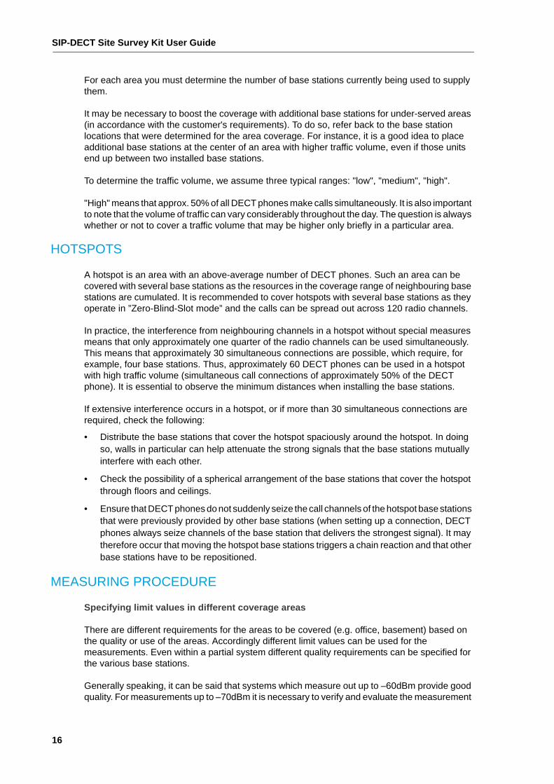
For each area you must determine the number of base stations currently being used to supply them.
It may be necessary to boost the coverage with additional base stations for under-served areas (in accordance with the customer's requirements). To do so, refer back to the base station locations that were determined for the area coverage. For instance, it is a good idea to place additional base stations at the center of an area with higher traffic volume, even if those units end up between two installed base stations.
To determine the traffic volume, we assume three typical ranges: "low", "medium", "high".
"High" means that approx. 50% of all DECT phones make calls simultaneously. It is also important to note that the volume of traffic can vary considerably throughout the day. The question is always whether or not to cover a traffic volume that may be higher only briefly in a particular area.
HOTSPOTS
A hotspot is an area with an above-average number of DECT phones. Such an area can be covered with several base stations as the resources in the coverage range of neighbouring base stations are cumulated. It is recommended to cover hotspots with several base stations as they operate in ”Zero-Blind-Slot mode” and the calls can be spread out across 120 radio channels.
In practice, the interference from neighbouring channels in a hotspot without special measures means that only approximately one quarter of the radio channels can be used simultaneously. This means that approximately 30 simultaneous connections are possible, which require, for example, four base stations. Thus, approximately 60 DECT phones can be used in a hotspot with high traffic volume (simultaneous call connections of approximately 50% of the DECT phone). It is essential to observe the minimum distances when installing the base stations.
If extensive interference occurs in a hotspot, or if more than 30 simultaneous connections are required, check the following:
• Distribute the base stations that cover the hotspot spaciously around the hotspot. In doing so, walls in particular can help attenuate the strong signals that the base stations mutually interfere with each other.
• Check the possibility of a spherical arrangement of the base stations that cover the hotspot through floors and ceilings.
• Ensure that DECT phones do not suddenly seize the call channels of the hotspot base stations that were previously provided by other base stations (when setting up a connection, DECT phones always seize channels of the base station that delivers the strongest signal). It may therefore occur that moving the hotspot base stations triggers a chain reaction and that other base stations have to be repositioned.
MEASURING PROCEDURE
Specifying limit values in different coverage areas
There are different requirements for the areas to be covered (e.g. office, basement) based on the quality or use of the areas. Accordingly different limit values can be used for the measurements. Even within a partial system different quality requirements can be specified for the various base stations.
Generally speaking, it can be said that systems which measure out up to –60dBm provide good quality. For measurements up to –70dBm it is necessary to verify and evaluate the measurement
Planning and Site Survey
17
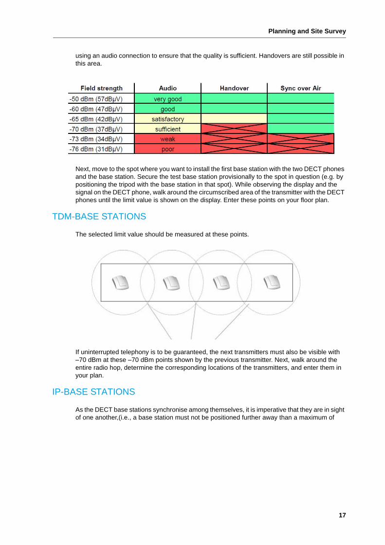
using an audio connection to ensure that the quality is sufficient. Handovers are still possible in this area.
Next, move to the spot where you want to install the first base station with the two DECT phones and the base station. Secure the test base station provisionally to the spot in question (e.g. by positioning the tripod with the base station in that spot). While observing the display and the signal on the DECT phone, walk around the circumscribed area of the transmitter with the DECT phones until the limit value is shown on the display. Enter these points on your floor plan.
TDM-BASE STATIONS
The selected limit value should be measured at these points.
If uninterrupted telephony is to be guaranteed, the next transmitters must also be visible with –70 dBm at these –70 dBm points shown by the previous transmitter. Next, walk around the entire radio hop, determine the corresponding locations of the transmitters, and enter them in your plan.
IP-BASE STATIONS
As the DECT base stations synchronise among themselves, it is imperative that they are in sight of one another,(i.e., a base station must not be positioned further away than a maximum of
SIP-DECT Site Survey Kit User Guide
18
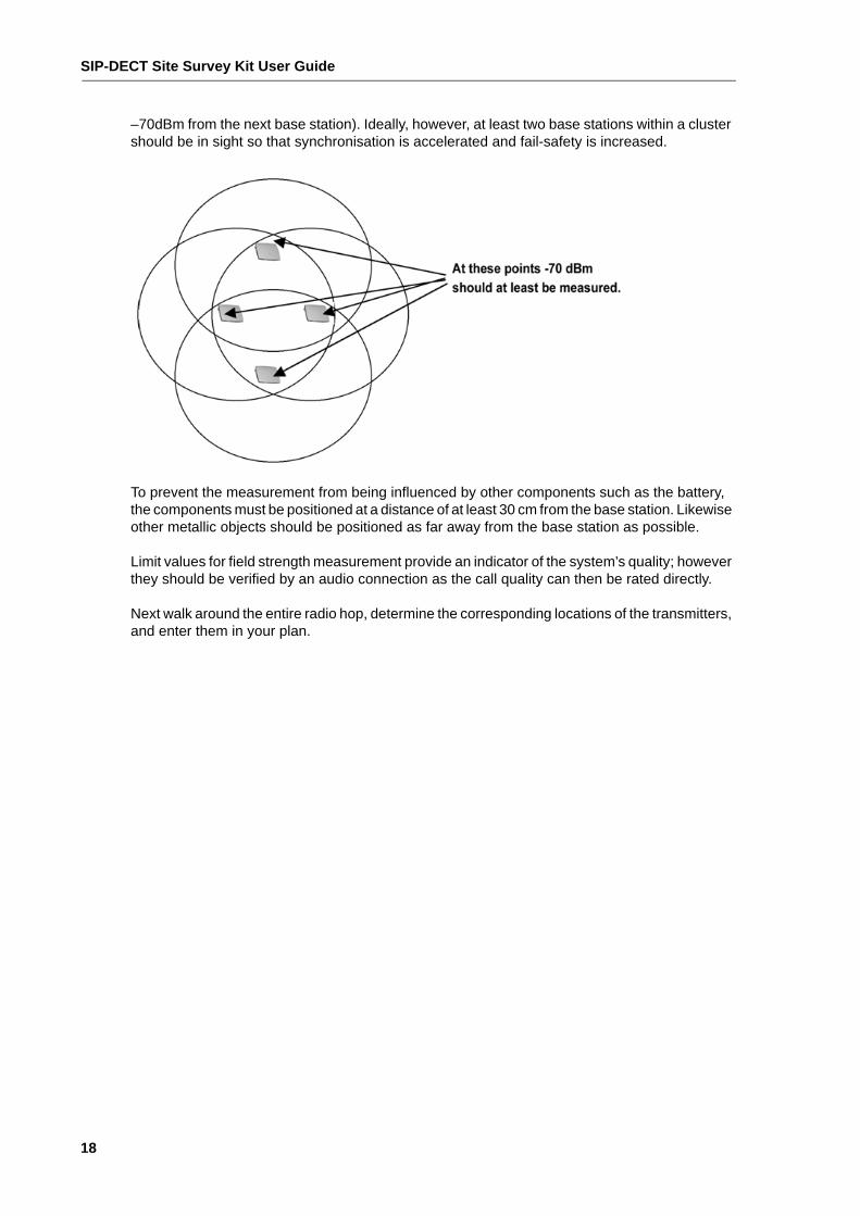
–70dBm from the next base station). Ideally, however, at least two base stations within a cluster should be in sight so that synchronisation is accelerated and fail-safety is increased.
To prevent the measurement from being influenced by other components such as the battery, the components must be positioned at a distance of at least 30 cm from the base station. Likewise other metallic objects should be positioned as far away from the base station as possible.
Limit values for field strength measurement provide an indicator of the system’s quality; however they should be verified by an audio connection as the call quality can then be rated directly.
Next walk around the entire radio hop, determine the corresponding locations of the transmitters, and enter them in your plan.
Basics
19
BASICS
If a DECT system is to operate faultlessly, a homogeneous radio hop must be created that provides sufficient calling opportunities (number of simultaneous connections) at the locations required by the customer. The SIP-DECT Site Survey Kit serves this purpose.
With the equipment included in the SIP-DECT Site Survey Kit it is possible to determine the locations for the DECT base stations as required by the customer.
The base stations are called Radio Fixed Parts (RFP). All 120 DECT duplex channels are used.
INITIAL CONSIDERATIONS
Generally speaking, the test kit can be used for two types of applications: planning a new project or expanding an existing system. Both cases require in-depth consultation with the customer and a maximum of detailed information so that the complex system can be configured as effectively as possible. Providing the customer with comprehensive information allows him to make full use of the available features, which will in turn result in high levels not only of application efficiency but also customer satisfaction.
For new projects in particular, the following considerations must be taken into account:
• Radio coverage area, capacity in terms of the number of connections (“traffic density”)
• Known problem areas and what to do about them
• Handover behaviour and what happens during a handover
• Cordless groups and other features
With a project extension, a distinction must be made between the following possibilities:
• Additional DECT phones without any notable increase in traffic simply require new entries in the PBX numbering plan.
• Additional DECT phones with additional traffic require not only the entries in the PBX numbering plan, but also a verification of the existing radio cells to determine whether any boost is required using additional base stations.
• Coverage required over a greater area
COVERAGE AREA
The supply range of a DECT system can vary greatly from a geographical point of view. In most cases, the bulk of the supply range is inside buildings.
A DECT system always relates to a PABX. Handover to a neighbouring DECT system in another PABX never occurs, even if the DECT phone is logged on in both systems.
The planning can be carried out for both systems, however, as the measuring equipment is used without a PBX.
SIP-DECT Site Survey Kit User Guide
20
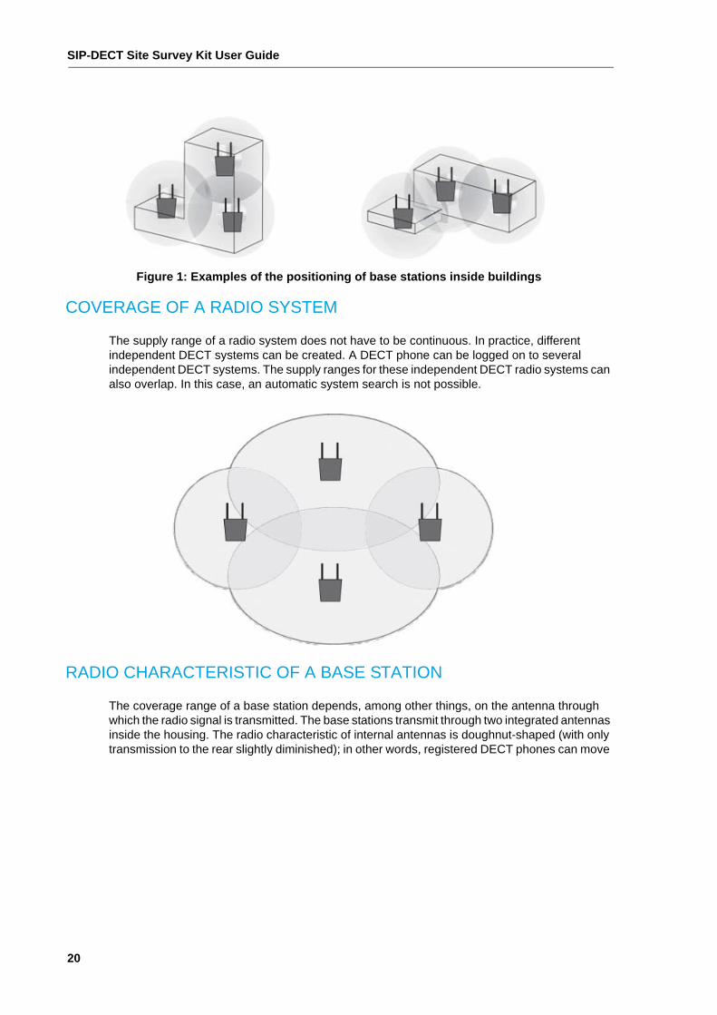
Figure 1: Examples of the positioning of base stations inside buildings
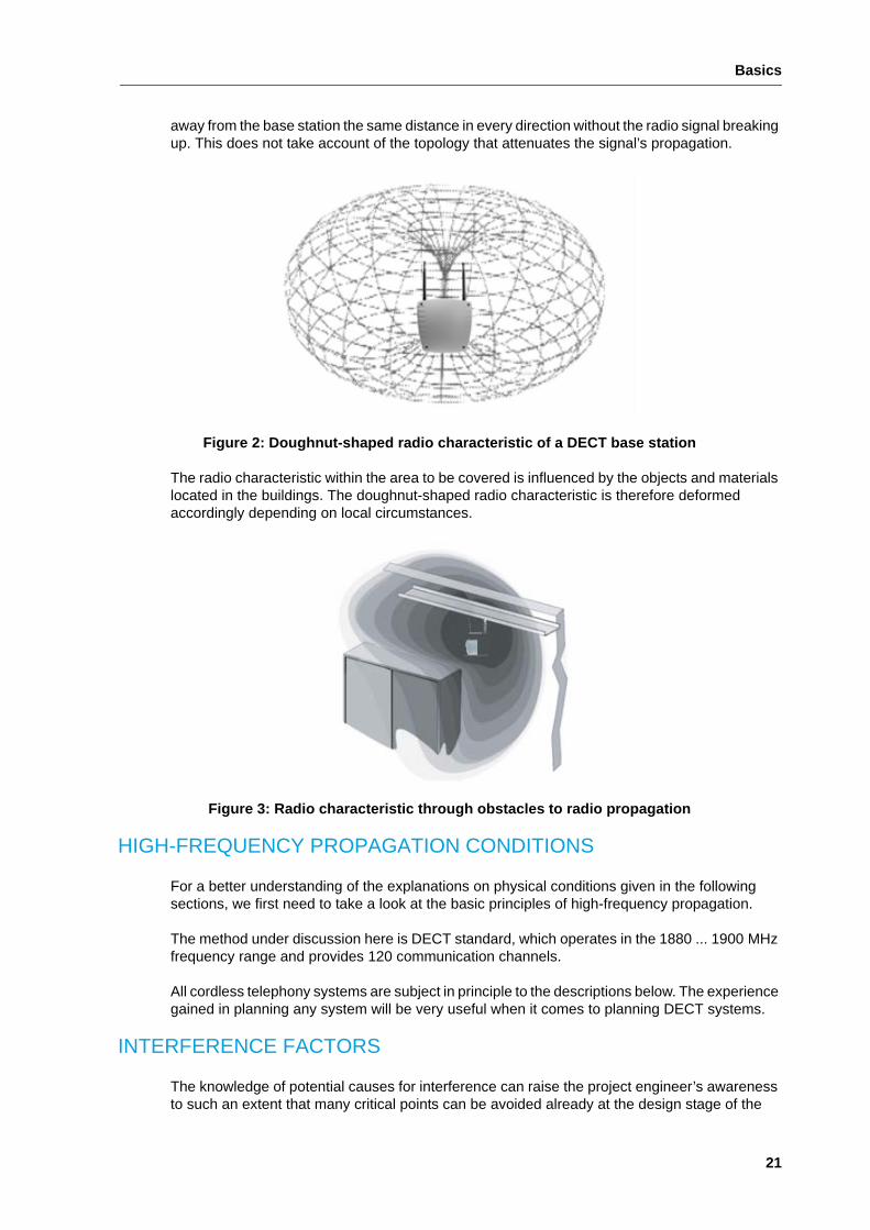
COVERAGE OF A RADIO SYSTEM
The supply range of a radio system does not have to be continuous. In practice, different independent DECT systems can be created. A DECT phone can be logged on to several independent DECT systems. The supply ranges for these independent DECT radio systems can also overlap. In this case, an automatic system search is not possible.
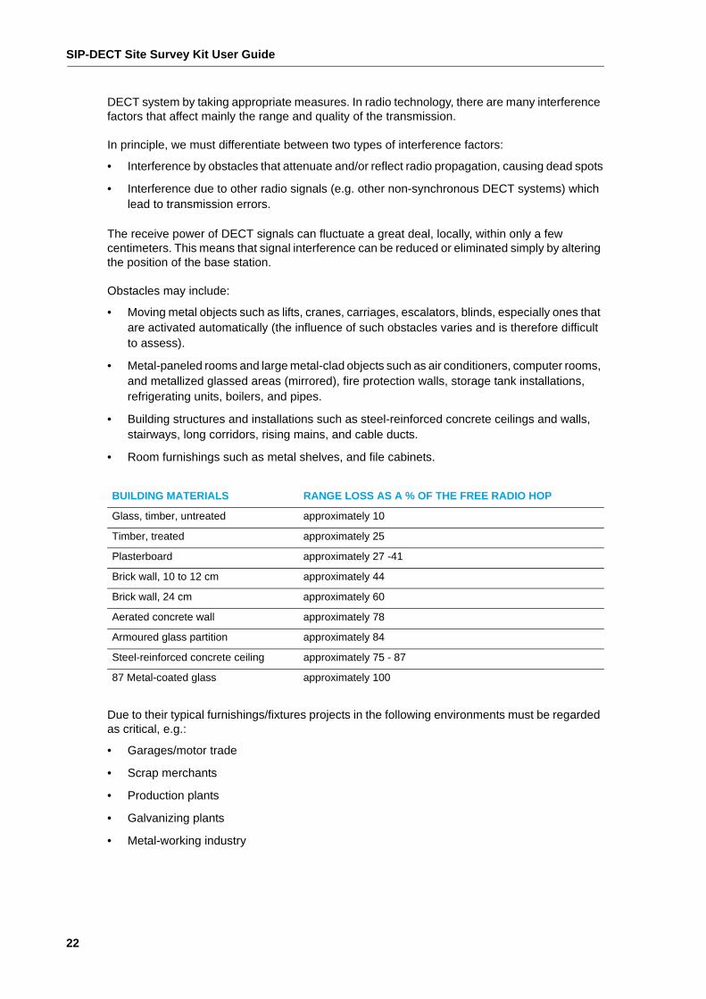
RADIO CHARACTERISTIC OF A BASE STATION
The coverage range of a base station depends, among other things, on the antenna through which the radio signal is transmitted. The base stations transmit through two integrated antennas inside the housing. The radio characteristic of internal antennas is doughnut-shaped (with only transmission to the rear slightly diminished); in other words, registered DECT phones can move
Basics
21
away from the base station the same distance in every direction without the radio signal breaking up. This does not take account of the topology that attenuates the signal’s propagation.
Figure 2: Doughnut-shaped radio characteristic of a DECT base station
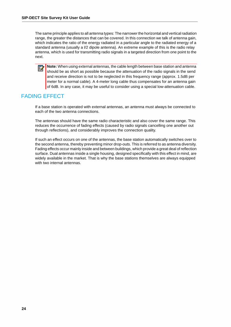
The radio characteristic within the area to be covered is influenced by the objects and materials located in the buildings. The doughnut-shaped radio characteristic is therefore deformed accordingly depending on local circumstances.
Figure 3: Radio characteristic through obstacles to radio propagation
HIGH-FREQUENCY PROPAGATION CONDITIONS
For a better understanding of the explanations on physical conditions given in the following sections, we first need to take a look at the basic principles of high-frequency propagation.
The method under discussion here is DECT standard, which operates in the 1880 ... 1900 MHz frequency range and provides 120 communication channels.
All cordless telephony systems are subject in principle to the descriptions below. The experience gained in planning any system will be very useful when it comes to planning DECT systems.
INTERFERENCE FACTORS
The knowledge of potential causes for interference can raise the project engineer’s awareness to such an extent that many critical points can be avoided already at the design stage of the
SIP-DECT Site Survey Kit User Guide
22
DECT system by taking appropriate measures. In radio technology, there are many interference factors that affect mainly the range and quality of the transmission.
In principle, we must differentiate between two types of interference factors:
• Interference by obstacles that attenuate and/or reflect radio propagation, causing dead spots
• Interference due to other radio signals (e.g. other non-synchronous DECT systems) which lead to transmission errors.
The receive power of DECT signals can fluctuate a great deal, locally, within only a few centimeters. This means that signal interference can be reduced or eliminated simply by altering the position of the base station.
Obstacles may include:
• Moving metal objects such as lifts, cranes, carriages, escalators, blinds, especially ones that are activated automatically (the influence of such obstacles varies and is therefore difficult to assess).
• Metal-paneled rooms and large metal-clad objects such as air conditioners, computer rooms, and metallized glassed areas (mirrored), fire protection walls, storage tank installations, refrigerating units, boilers, and pipes.
• Building structures and installations such as steel-reinforced concrete ceilings and walls, stairways, long corridors, rising mains, and cable ducts.
• Room furnishings such as metal shelves, and file cabinets.
Due to their typical furnishings/fixtures projects in the following environments must be regarded as critical, e.g.:
• Garages/motor trade
• Scrap merchants
• Production plants
• Galvanizing plants
• Metal-working industry
BUILDING MATERIALS RANGE LOSS AS A % OF THE FREE RADIO HOP
Glass, timber, untreated approximately 10
Timber, treated approximately 25
Plasterboard approximately 27 -41
Brick wall, 10 to 12 cm approximately 44
Brick wall, 24 cm approximately 60
Aerated concrete wall approximately 78
Armoured glass partition approximately 84
Steel-reinforced concrete ceiling approximately 75 - 87
87 Metal-coated glass approximately 100

Basics
23
RECEPTION CONDITIONS
Optimizing range is a fundamental challenge of radio technology. The reception in marginal zones is patchy at best. Practical measurements are carried out on the premises to determine the range.
The following guidance can help users achieve optimum results:
• You can usually improve the connection quality through minor changes in location, e.g. by turning your head or your body.
• Avoid making phone calls in unsuitable places, for example in lifts. Users should be made aware of these zones during instruction.
USING EXTERNAL ANTENNAS
External antennas are useful for:
• rectifying radio signals, thereby achieving a greater range in one particular direction (e.g., to provide coverage to remote ancillary buildings).
• providing coverage to an outside area without the shell of the building obstructing the propagation of the radio signals (this is achieved by mounting the base station within the building and the antennas outside it).
There are different types of antennas, each with highly specific radio characteristics for meeting individual coverage requirements; they are best illustrated by radiation patterns.
Radio hop of a (horizontal/vertical) directional antenna, usually suitable for remote isolated buildings or areas:
Radio hop of a (horizontal/vertical) omni-directional antenna, usually suitable for a wide-ranging area/building.
SIP-DECT Site Survey Kit User Guide
24
The same principle applies to all antenna types: The narrower the horizontal and vertical radiation range, the greater the distances that can be covered. In this connection we talk of antenna gain, which indicates the ratio of the energy radiated in a particular angle to the radiated energy of a standard antenna (usually a l/2 dipole antenna). An extreme example of this is the radio relay antenna, which is used for transmitting radio signals in a targeted direction from one point to the next.
FADING EFFECT
If a base station is operated with external antennas, an antenna must always be connected to each of the two antenna connections.
The antennas should have the same radio characteristic and also cover the same range. This reduces the occurrence of fading effects (caused by radio signals cancelling one another out through reflections), and considerably improves the connection quality.
If such an effect occurs on one of the antennas, the base station automatically switches over to the second antenna, thereby preventing minor drop-outs. This is referred to as antenna diversity. Fading effects occur mainly inside and between buildings, which provide a great deal of reflection surface. Dual antennas inside a single housing, designed specifically with this effect in mind, are widely available in the market. That is why the base stations themselves are always equipped with two internal antennas.
Note: When using external antennas, the cable length between base station and antenna should be as short as possible because the attenuation of the radio signals in the send and receive direction is not to be neglected in this frequency range (approx. 1.5dB per meter for a normal cable). A 4-meter long cable thus compensates for an antenna gain of 6dB. In any case, it may be useful to consider using a special low-attenuation cable.

Appendix A
TECHNICAL DATA

SIP-DECT Site Survey Kit User Guide
26
TECHNICAL SPECIFICATIONS
Note that the metric system is used in Canada, while Imperial measurements are used in the USA.
SPECIFICATION USA, CANADA EMEA
Frequencies 1920 MHz to 1930 MHz (UPCS)
1800 MHz to 1900 MHz
Modulation GFSK GFSK
Maximum transmission power (20 dBm) 250 mW (24 dBm)
Duplex method Time-division mulitplex, 10 ms frame length
Time-division mulitplex, 10 ms frame length
Channel subdivision 1728 kHz 1728 kHz
Number of carrier frequencies 5 10
Number of time slots 24 24
Number of channels 60 duplex channels 120 duplex channels
Bitrate 1152 kbps 1152 kbps
Net data rate - voice 32 kbit/s (full slot, G.726)
64 kbit/s (long slot, G.722)
32 kbit/s (full slot, G.726)
64 kbit/s (long slot, G.722)
Net data rate - signalling 6.4 kbit/s 6,4 kbit/s
Range up to 980 ft outdoors
up to 160 ft indoors
up to 300 m outdoors
up to 50 m indoors

© Copyright 2015, Mitel Networks Corporation. All Rights Reserved. The Mitel word and logo are trademarks of Mitel Networks Corporation. Any reference to third party trademarks are for reference only and Mitel makes no representation of ownership of these marks.