Embed Size (px)
Citation preview
Slim Relay G2RV 3
Slim RelayG2RV
The World's First Industrial Slim Relay
• Large plug-in terminals for easy connection.
• LED indicator and mechanical flag to check operation.• Transparent housing enables checking relay condition.• Slim outline to save space.
• Push-in terminals and accessories for easy wiring.
NTLP: WAITING FOR PHOTO
Model Number Structure
Model Number Legend
1. Auxiliary Type DesignationSL: Slim relay and socket combination
2. Wire Connection7: Screw terminals5: Push-in terminals
3. Relay LED0: Without LED1: LED indicator
4. Relay Pushbutton0: Without pushbutton1: Lockable push-to-test
5. Input Voltage
1 2 3 4 5G2RV-SL @ @ @ - @
4 Slim Relay G2RV
Ordering Information
List of Models
Relay and Socket Combinations
Specifications
Input Ratings
Contact Ratings
Note: P level: λ60 = 0.1 x 10⁻⁶/operation
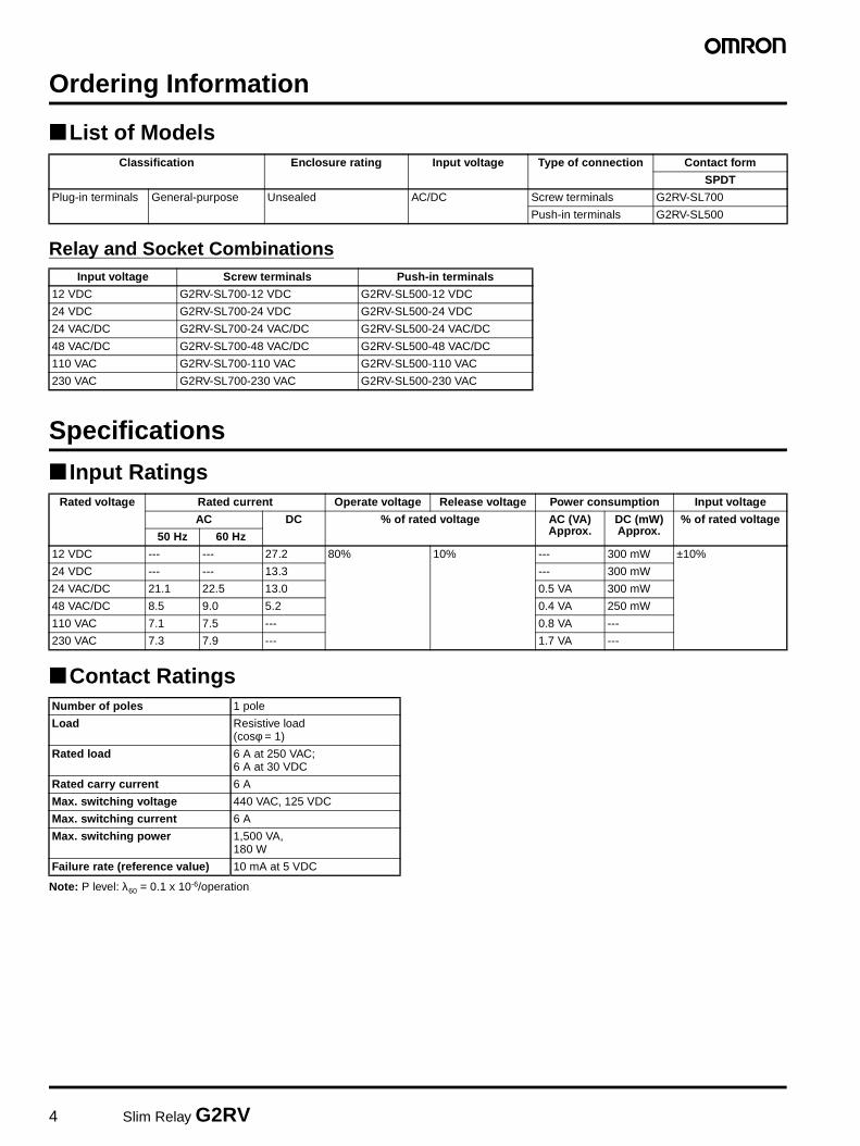
Classification Enclosure rating Input voltage Type of connection Contact form
SPDT
Plug-in terminals General-purpose Unsealed AC/DC Screw terminals G2RV-SL700
Push-in terminals G2RV-SL500
Input voltage Screw terminals Push-in terminals
12 VDC G2RV-SL700-12 VDC G2RV-SL500-12 VDC
24 VDC G2RV-SL700-24 VDC G2RV-SL500-24 VDC
24 VAC/DC G2RV-SL700-24 VAC/DC G2RV-SL500-24 VAC/DC
48 VAC/DC G2RV-SL700-48 VAC/DC G2RV-SL500-48 VAC/DC
110 VAC G2RV-SL700-110 VAC G2RV-SL500-110 VAC
230 VAC G2RV-SL700-230 VAC G2RV-SL500-230 VAC
Rated voltage Rated current Operate voltage Release voltage Power consumption Input voltage
AC DC % of rated voltage AC (VA) Approx.
DC (mW) Approx.
% of rated voltage
50 Hz 60 Hz
12 VDC --- --- 27.2 80% 10% --- 300 mW ±10%
24 VDC --- --- 13.3 --- 300 mW
24 VAC/DC 21.1 22.5 13.0 0.5 VA 300 mW
48 VAC/DC 8.5 9.0 5.2 0.4 VA 250 mW
110 VAC 7.1 7.5 --- 0.8 VA ---
230 VAC 7.3 7.9 --- 1.7 VA ---
Number of poles 1 pole
Load Resistive load(cosφ = 1)
Rated load 6 A at 250 VAC;6 A at 30 VDC
Rated carry current 6 A
Max. switching voltage 440 VAC, 125 VDC
Max. switching current 6 A
Max. switching power 1,500 VA,180 W
Failure rate (reference value) 10 mA at 5 VDC
Slim Relay G2RV 5
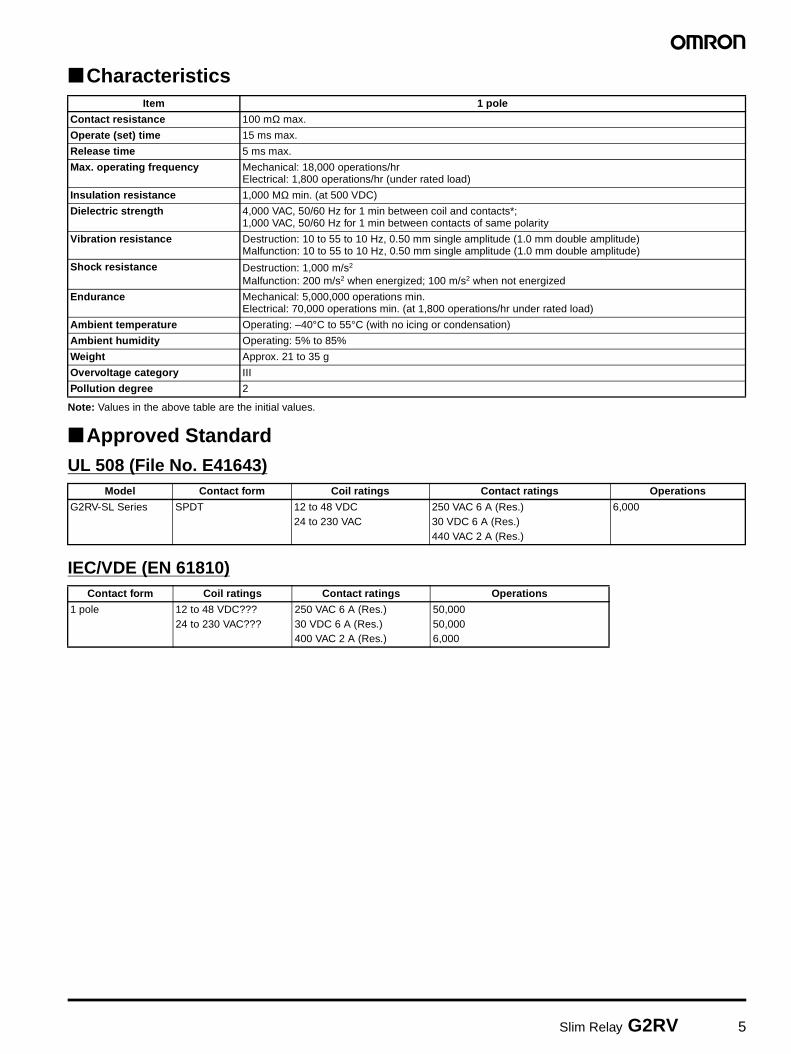
Characteristics
Note: Values in the above table are the initial values.
Approved StandardUL 508 (File No. E41643)
IEC/VDE (EN 61810)
Item 1 pole
Contact resistance 100 mΩ max.
Operate (set) time 15 ms max.
Release time 5 ms max.
Max. operating frequency Mechanical: 18,000 operations/hrElectrical: 1,800 operations/hr (under rated load)
Insulation resistance 1,000 MΩ min. (at 500 VDC)
Dielectric strength 4,000 VAC, 50/60 Hz for 1 min between coil and contacts*;1,000 VAC, 50/60 Hz for 1 min between contacts of same polarity
Vibration resistance Destruction: 10 to 55 to 10 Hz, 0.50 mm single amplitude (1.0 mm double amplitude)Malfunction: 10 to 55 to 10 Hz, 0.50 mm single amplitude (1.0 mm double amplitude)
Shock resistance Destruction: 1,000 m/s2
Malfunction: 200 m/s2 when energized; 100 m/s2 when not energized
Endurance Mechanical: 5,000,000 operations min.Electrical: 70,000 operations min. (at 1,800 operations/hr under rated load)
Ambient temperature Operating: –40°C to 55°C (with no icing or condensation)
Ambient humidity Operating: 5% to 85%
Weight Approx. 21 to 35 g
Overvoltage category III
Pollution degree 2
Model Contact form Coil ratings Contact ratings Operations
G2RV-SL Series SPDT 12 to 48 VDC24 to 230 VAC
250 VAC 6 A (Res.)30 VDC 6 A (Res.)440 VAC 2 A (Res.)
6,000
Contact form Coil ratings Contact ratings Operations
1 pole 12 to 48 VDC???24 to 230 VAC???
250 VAC 6 A (Res.)30 VDC 6 A (Res.)400 VAC 2 A (Res.)
50,00050,0006,000
6 Slim Relay G2RV
Accessories
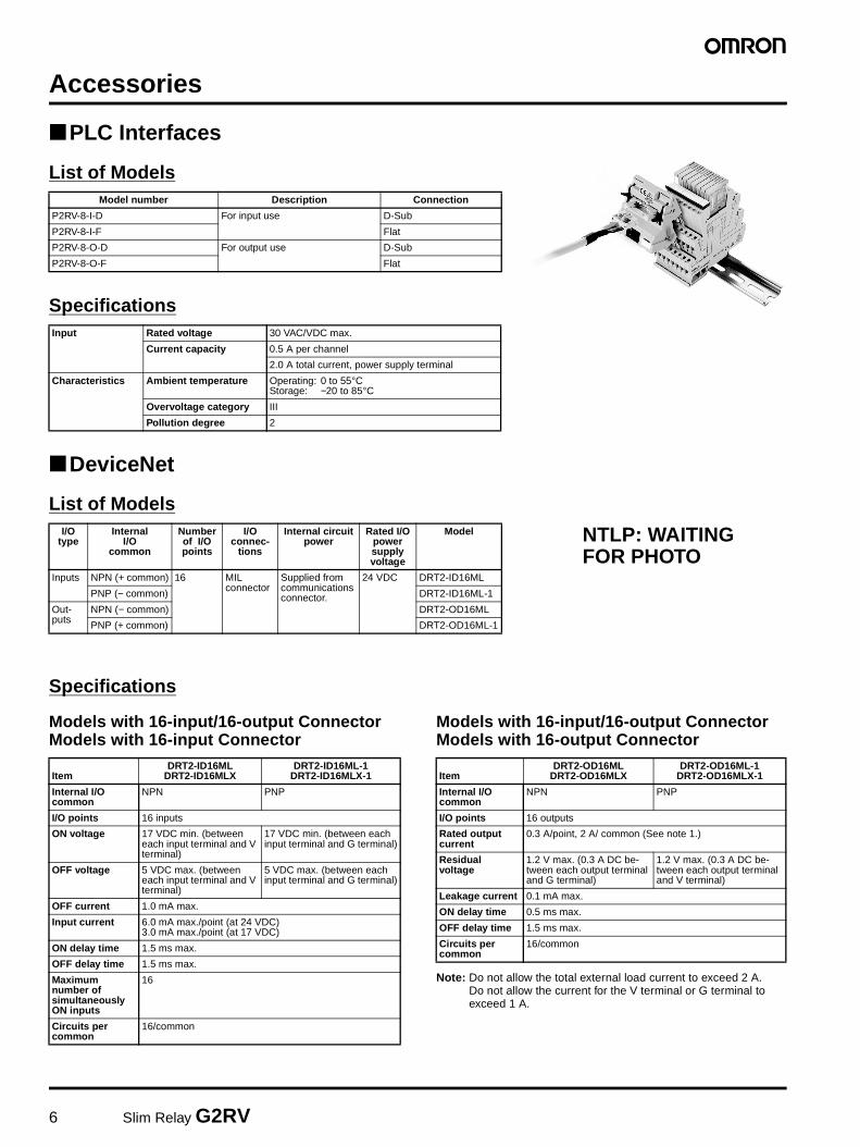
PLC Interfaces
List of Models
Specifications
DeviceNet
List of Models
Specifications
Models with 16-input/16-output ConnectorModels with 16-input Connector
Models with 16-input/16-output ConnectorModels with 16-output Connector
Note: Do not allow the total external load current to exceed 2 A. Do not allow the current for the V terminal or G terminal to exceed 1 A.
Model number Description Connection
P2RV-8-I-D For input use D-Sub
P2RV-8-I-F Flat
P2RV-8-O-D For output use D-Sub
P2RV-8-O-F Flat
Input Rated voltage 30 VAC/VDC max.
Current capacity 0.5 A per channel
2.0 A total current, power supply terminal
Characteristics Ambient temperature Operating: 0 to 55°CStorage: −20 to 85°C
Overvoltage category III
Pollution degree 2
I/Otype
Internal I/O
common
Number of I/O points
I/Oconnec-
tions
Internal circuit power
Rated I/O power supply voltage
Model
Inputs NPN (+ common) 16 MIL connector
Supplied from communications connector.
24 VDC DRT2-ID16ML
PNP (− common) DRT2-ID16ML-1
Out-puts
NPN (− common) DRT2-OD16ML
PNP (+ common) DRT2-OD16ML-1
NTLP: WAITING FOR PHOTO
ItemDRT2-ID16ML
DRT2-ID16MLXDRT2-ID16ML-1
DRT2-ID16MLX-1
Internal I/O common
NPN PNP
I/O points 16 inputs
ON voltage 17 VDC min. (between each input terminal and V terminal)
17 VDC min. (between each input terminal and G terminal)
OFF voltage 5 VDC max. (between each input terminal and V terminal)
5 VDC max. (between each input terminal and G terminal)
OFF current 1.0 mA max.
Input current 6.0 mA max./point (at 24 VDC)3.0 mA max./point (at 17 VDC)
ON delay time 1.5 ms max.
OFF delay time 1.5 ms max.
Maximum number of simultaneously ON inputs
16
Circuits per common
16/common
ItemDRT2-OD16ML
DRT2-OD16MLXDRT2-OD16ML-1
DRT2-OD16MLX-1
Internal I/O common
NPN PNP
I/O points 16 outputs
Rated output current
0.3 A/point, 2 A/ common (See note 1.)
Residual voltage
1.2 V max. (0.3 A DC be-tween each output terminal and G terminal)
1.2 V max. (0.3 A DC be-tween each output terminal and V terminal)
Leakage current 0.1 mA max.
ON delay time 0.5 ms max.
OFF delay time 1.5 ms max.
Circuits per common
16/common
Slim Relay G2RV 7
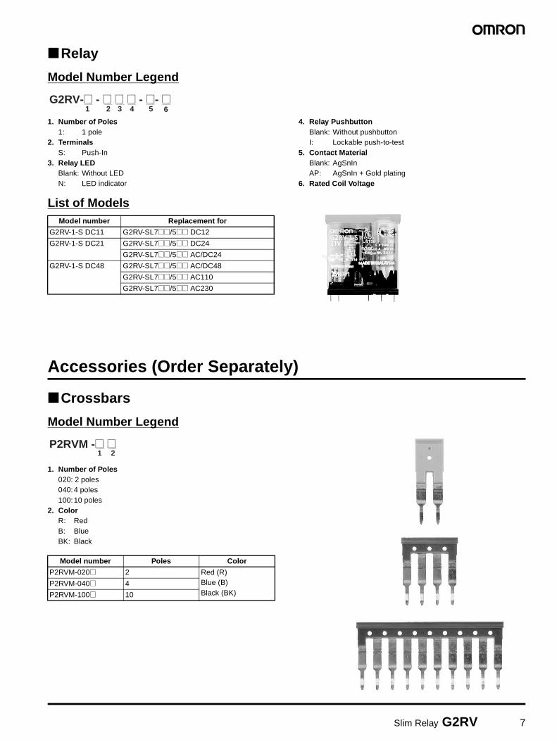
Relay
Model Number Legend
1. Number of Poles1: 1 pole
2. TerminalsS: Push-In
3. Relay LEDBlank: Without LEDN: LED indicator
4. Relay PushbuttonBlank: Without pushbuttonI: Lockable push-to-test
5. Contact MaterialBlank: AgSnInAP: AgSnIn + Gold plating
6. Rated Coil Voltage
List of Models
Accessories (Order Separately)
Crossbars
Model Number Legend
1. Number of Poles020: 2 poles040:4 poles100:10 poles
2. ColorR: RedB: BlueBK: Black
1 2 3 4 5 6G2RV-@ - @ @ @ - @- @
Model number Replacement for
G2RV-1-S DC11 G2RV-SL7@@/5@@ DC12
G2RV-1-S DC21 G2RV-SL7@@/5@@ DC24
G2RV-SL7@@/5@@ AC/DC24
G2RV-1-S DC48 G2RV-SL7@@/5@@ AC/DC48
G2RV-SL7@@/5@@ AC110
G2RV-SL7@@/5@@ AC230
Model number Poles Color
P2RVM-020@ 2 Red (R)Blue (B)Black (BK)
P2RVM-040@ 4
P2RVM-100@ 10
1 2P2RVM -@ @
8 Slim Relay G2RV
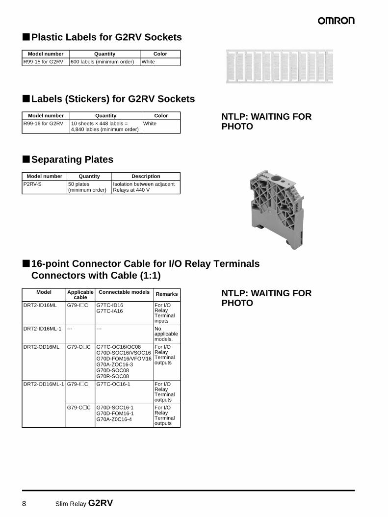
Plastic Labels for G2RV Sockets
Labels (Stickers) for G2RV Sockets
Separating Plates
16-point Connector Cable for I/O Relay TerminalsConnectors with Cable (1:1)
Model number Quantity Color
R99-15 for G2RV 600 labels (minimum order) White
Model number Quantity Color
R99-16 for G2RV 10 sheets × 448 labels = 4,840 lables (minimum order)
WhiteNTLP: WAITING FOR PHOTO
Model number Quantity Description
P2RV-S 50 plates (minimum order)
Isolation between adjacent Relays at 440 V
Model Applicablecable
Connectable models Remarks
DRT2-ID16ML G79-I@C G7TC-ID16G7TC-IA16
For I/O RelayTerminal inputs
DRT2-ID16ML-1 --- --- No applicablemodels.
DRT2-OD16ML G79-O@C G7TC-OC16/OC08G70D-SOC16/VSOC16G70D-FOM16/VFOM16G70A-ZOC16-3G70D-SOC08G70R-SOC08
For I/O Relay Terminal outputs
DRT2-OD16ML-1 G79-I@C G7TC-OC16-1 For I/O Relay Terminal outputs
G79-O@C G70D-SOC16-1G70D-FOM16-1G70A-Z0C16-4
For I/O Relay Terminal outputs
NTLP: WAITING FOR PHOTO
Slim Relay G2RV 9
Connections
PLC InterfacesP2RVC-8-I-D
NTLP: WAITING FOR PHOTO
NTLP: WAITING FOR GRAPHIC
P2RVC-8-I-F
NTLP: WAITING FOR PHOTO
NTLP: WAITING FOR GRAPHIC
P2RVC-8-O-D
NTLP: WAITING FOR PHOTO
NTLP: WAITING FOR GRAPHIC
P2RVC-8-O-F
NTLP: WAITING FOR PHOTO
NTLP: WAITING FOR GRAPHIC
10 Slim Relay G2RV
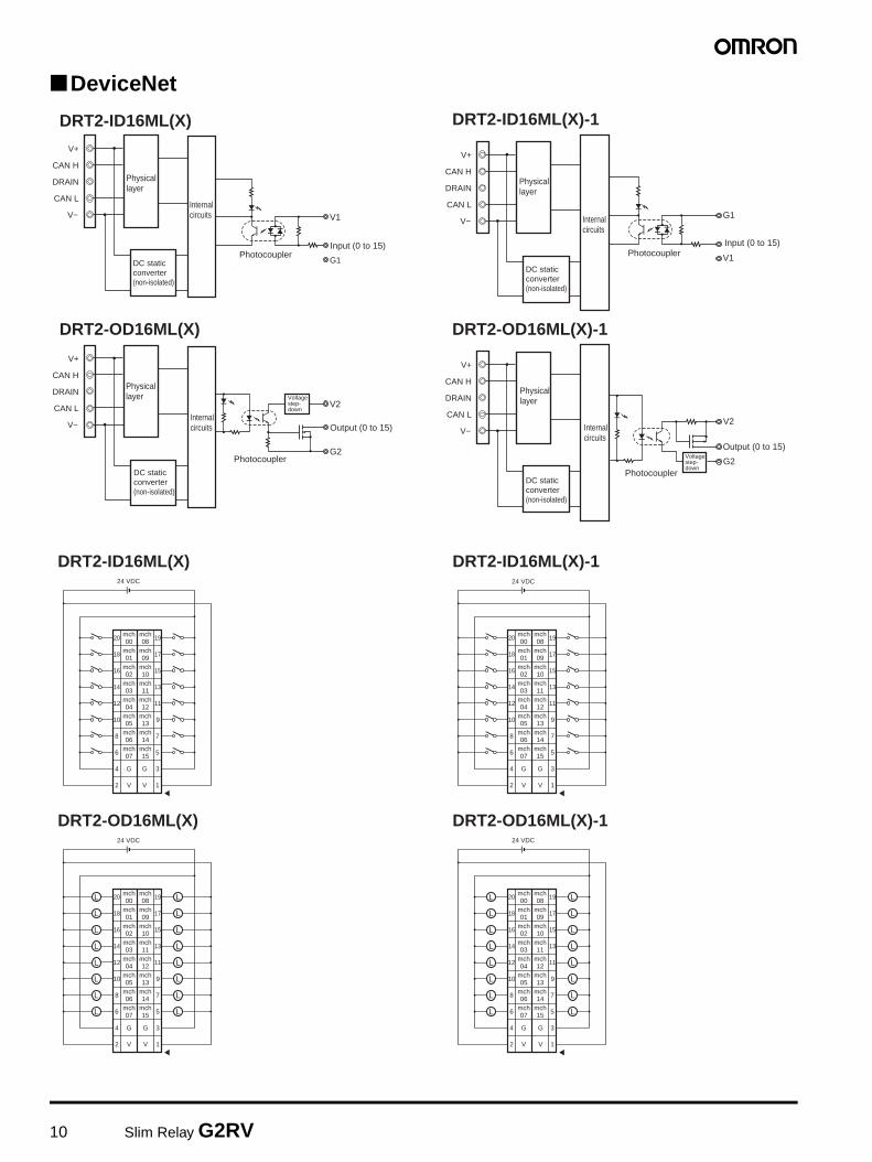
DeviceNet
DRT2-ID16ML(X) DRT2-ID16ML(X)-1
DRT2-OD16ML(X) DRT2-OD16ML(X)-1
V1
Input (0 to 15)
G1
V+
CAN H
DRAIN
CAN L
V−
DC static converter (non-isolated)
G1
V1
V+
CAN H
DRAIN
CAN L
V−
V2
G2
V+
CAN H
DRAIN
CAN L
V− V2
G2
V+
CAN H
DRAIN
CAN L
V−
DRT2-ID16ML(X) DRT2-ID16ML(X)-1
DRT2-OD16ML(X) DRT2-OD16ML(X)-1
24 VDC
1920
V
G
V
G
1718
1516
1314
11
10
12
9
8
6
4
2
7
5
3
1
mch03
mch11
mch02
mch10
mch01
mch09
mch00
mch08
mch04
mch12
mch05
mch13
mch06
mch14
mch07
mch15
24 VDC
1920
V
G
V
G
1718
1516
1314
11
10
12
9
8
6
4
2
7
5
3
1
mch03
mch11
mch02
mch10
mch01
mch09
mch00
mch08
mch04
mch12
mch05
mch13
mch06
mch14
mch07
mch15
L
L
L
L
L
L
L
LL
L
L
L
L
L
L
L
24 VDC
1920
V
G
V
G
1718
1516
1314
11
10
12
9
8
6
4
2
7
5
3
1
mch03
mch11
mch02
mch10
mch01
mch09
mch00
mch08
mch04
mch12
mch05
mch13
mch06
mch14
mch07
mch15 L
L
L
L
L
L
L
L
L
L
L
L
L
L
L
L
24 VDC
1920
V
G
V
G
1718
1516
1314
11
10
12
9
8
6
4
2
7
5
3
1
mch03
mch11
mch02
mch10
mch01
mch09
mch00
mch08
mch04
mch12
mch05
mch13
mch06
mch14
mch07
mch15
Photocoupler
Internal circuits
Physical layer
DC static converter (non-isolated)
Voltagestep-down
Output (0 to 15) Internal circuits
Physical layer
DC static converter (non-isolated)
Input (0 to 15) Photocoupler
Internal circuits
Physical layer
Physical layer
DC static converter (non-isolated)
Internal circuits
Photocoupler
Output (0 to 15) Photocoupler Voltage
step-down
Slim Relay G2RV 11
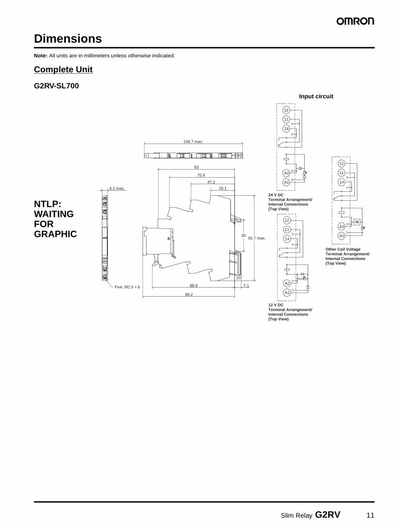
DimensionsNote: All units are in millimeters unless otherwise indicated.
Complete Unit
G2RV-SL700
12
11
14
A1
A2
24 V DCTerminal Arrangement/Internal Connections(Top View)
12
11
14
A1
A2
12 V DCTerminal Arrangement/Internal Connections(Top View)
12
11
14
A1
A2
Other Coil VoltageTerminal Arrangement/Internal Connections(Top View)
Five, M2.5 × 6
6.2 max.
99.2
7.188.9
26.1
47.2
70.9
83
106.7 max.
92.7 max.35
NTLP: WAITING FOR GRAPHIC
Input circuit
12 Slim Relay G2RV
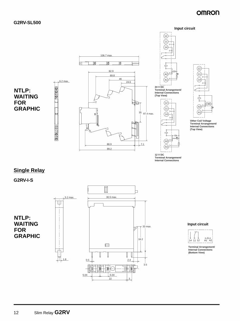
G2RV-SL500
Single Relay
G2RV-I-S
12
11
14
A1
A2
24 V DCTerminal Arrangement/Internal Connections(Top View)
12
11
14
A1
A2
12 V DCTerminal Arrangement/Internal Connections
12
11
14
A1
A2
Other Coil VoltageTerminal Arrangement/Internal Connections(Top View)
6.2 max.
99.2
88.9 7.1
24.646
69.8
82.9
106.7 max.
97.4 max.35
NTLP: WAITING FOR GRAPHIC
Input circuit
A2A1121114
Terminal Arrangement/Internal Connections(Bottom View)
30.5 max.
3.5
0.5 2.41.8
5.2 max.
5.04 5.04
322
33 max.
16.2
NTLP: WAITING FOR GRAPHIC
Input circuit

Slim Relay G2RV 13
Installation
ToolsA flat-blade screwdriver should be used to mount the cables.
Applicable Screwdriver Flat-blade, Parallel-tip, 2.5 mm diameter (3.0 mm max.)
Examples: FACOM AEF.2.5×75E (AEF. 3×75E)VESSEL No. 9900-(-)2.5×75 (No. 9900-(-)3×100)WAGO 210-119WIHA 260/2.5×40 (260/3×50)
*Chamfering the tip of the driver improves insertion when used as an exclusive tool.
Applicable Wires
Applicable Wire Sizes
G2RV-SL700 Series
G2RV-SL500 Series
Flat-blade, Parallel-tip
Flat-blade, Flared-tip2.5 dia. (3.0 mm max.)
Cannot be used.
Property Requirements
Cross-section with clamping yoke technology
0.5 to 2.5 mm2: Standard/solid (without ferrules)
0.5 to 2.5 mm2: Standard wires with ferrules with plastic collar
0.5 to 2.5 mm2: Standard wires with ferrules without plastic collar
4 mm2: SolidStripping length: 7 mm
Property Requirements
Cross-section with push-in technology
0.5 to 2.5 mm2: Standard/solid (without ferrules)
0.5 to 1.5 mm2: Standard wires with ferrules with plastic collar
0.5 to 2.5 mm2: Standard wires with ferrules without plastic collar
4 mm2: SolidStripping length: 12 mm
14 Slim Relay G2RV
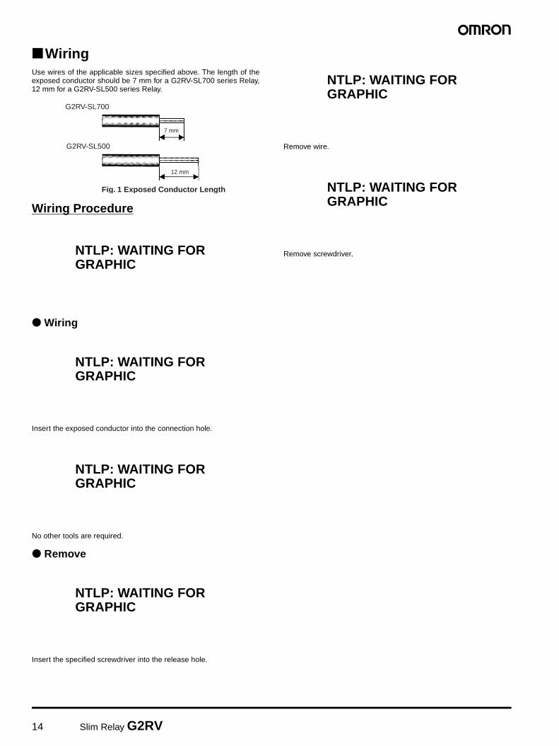
WiringUse wires of the applicable sizes specified above. The length of theexposed conductor should be 7 mm for a G2RV-SL700 series Relay,12 mm for a G2RV-SL500 series Relay.
Wiring Procedure
Wiring
Insert the exposed conductor into the connection hole.
No other tools are required.
Remove
Insert the specified screwdriver into the release hole.
Remove wire.
Remove screwdriver.
7 mm
Fig. 1 Exposed Conductor Length
12 mm
G2RV-SL700
G2RV-SL500
NTLP: WAITING FOR GRAPHIC
NTLP: WAITING FOR GRAPHIC
NTLP: WAITING FOR GRAPHIC
NTLP: WAITING FOR GRAPHIC
NTLP: WAITING FOR GRAPHIC
NTLP: WAITING FOR GRAPHIC

Slim Relay G2RV 15
Precautions
Precautions for Connection• Do not move the screwdriver up, down, or from side to side while it
is inserted in the hole. Doing so may cause damage to internal components (e.g., deformation of the clamp spring or cracks in the housing) or cause deterioration of insulation.
• Do not insert the screwdriver at an angle. Doing so may break the side of socket and result in a sort-circuit.
• Do not insert two or more wires in the hole. Wires may come in contact with the spring causing a temperature rise or be subject to sparks. (There are two wiring holes for each terminal.)
• Insert the screwdriver along the hole wall as shown below.
• If lubricating liquid, such as oil, is present on the tip of screwdriver, the screwdriver may fall out resulting in injury to the operator.
• Insert the screwdriver into the bottom of the hole. It may not be possible to connect cables properly if the screwdriver is inserted incorrectly.
General Precautions• Use the clip to prevent relays floating or falling out of the socket.• Do not use the product if it has been dropped on the ground.
Dropping the product may adversely affect performance.• Confirm that the socket is securely attached to the mounting track
before wiring. If the socket is mounted insecurely it may fall and injure the operator.
• Ensure that the socket is not charged during wiring and maintenance. Not doing so may result in electric shock.
• Do not pour water or cleansing agents on the product. Doing so may result in electric shock.
• Do not use the socket in locations subject to solvents or alkaline chemicals.
• Do not use the socket in locations subject to ultraviolet light (e.g., direct sunlight). Doing so may result in markings fading, rust, corrosion, or resin deterioration.
• Do not dispose of the product in fire.
Removing from Mounting RailTo remove the socket from the mounting rail, insert the tip of screwdriver in the fixture rail, and move it in the direction shown below.
NTLP: WAITING FOR GRAPHIC
NTLP: WAITING FOR GRAPHIC
NTLP: WAITING FOR GRAPHIC
NTLP: WAITING FOR GRAPHIC

In the interest of product improvement, specifications are subject to change without notice.
ALL DIMENSIONS SHOWN ARE IN MILLIMETERS.To convert millimeters into inches, multiply by 0.03937. To convert grams into ounces, multiply by 0.03527.
Cat. No. XXX-XX-XX
Printed in Japan0602-0.3M (1098) (O)
OMRON RELAY & DEVICES CorporationGeneral Purpose Relay Division
Marketing & Product Engineering Department
1110, Sugi, Yamaga-city, Kumamoto-Pref., 861-0596 Japan
Tel: (81)968-44-4149/Fax: (81)968-44-4107


![Features · FCC 47 Part 15 CB Report Selection Guide Part Input Output Output Efficiency Max. Capacitive Number Voltage Range (1)Voltage TCurrent typ. (2) Load [(VAC] [VDC] [mA] [%]](https://img.pdfslide.net/doc/110x75/5f32800162b92645966beff8/features-fcc-47-part-15-cb-report-selection-guide-part-input-output-output-efficiency.jpg)