Embed Size (px)
Citation preview

SMART-LIC Smart & Compact Battery Cell Management Systemfor Fully Electrical Vehicles
Jochen LangheimSTMicroelectronics
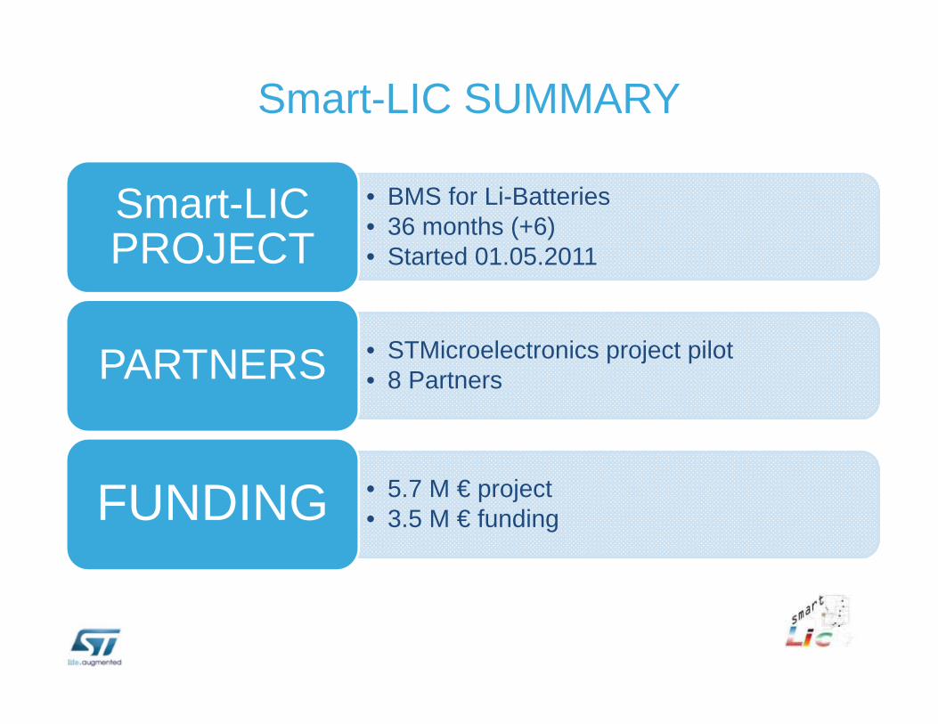
Smart-LIC SUMMARY
• BMS for Li-Batteries• 36 months (+6)• Started 01.05.2011
Smart-LICPROJECT
• STMicroelectronics project pilot• 8 PartnersPARTNERS
• 5.7 M € project• 3.5 M € fundingFUNDING
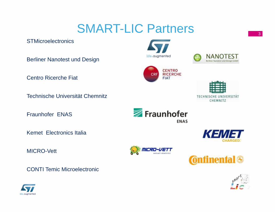
SMART-LIC PartnersSTMicroelectronics
Berliner Nanotest und Design
Centro Ricerche Fiat
Technische Universität Chemnitz
Fraunhofer ENAS
Kemet Electronics Italia
MICRO-Vett
CONTI Temic Microelectronic
3
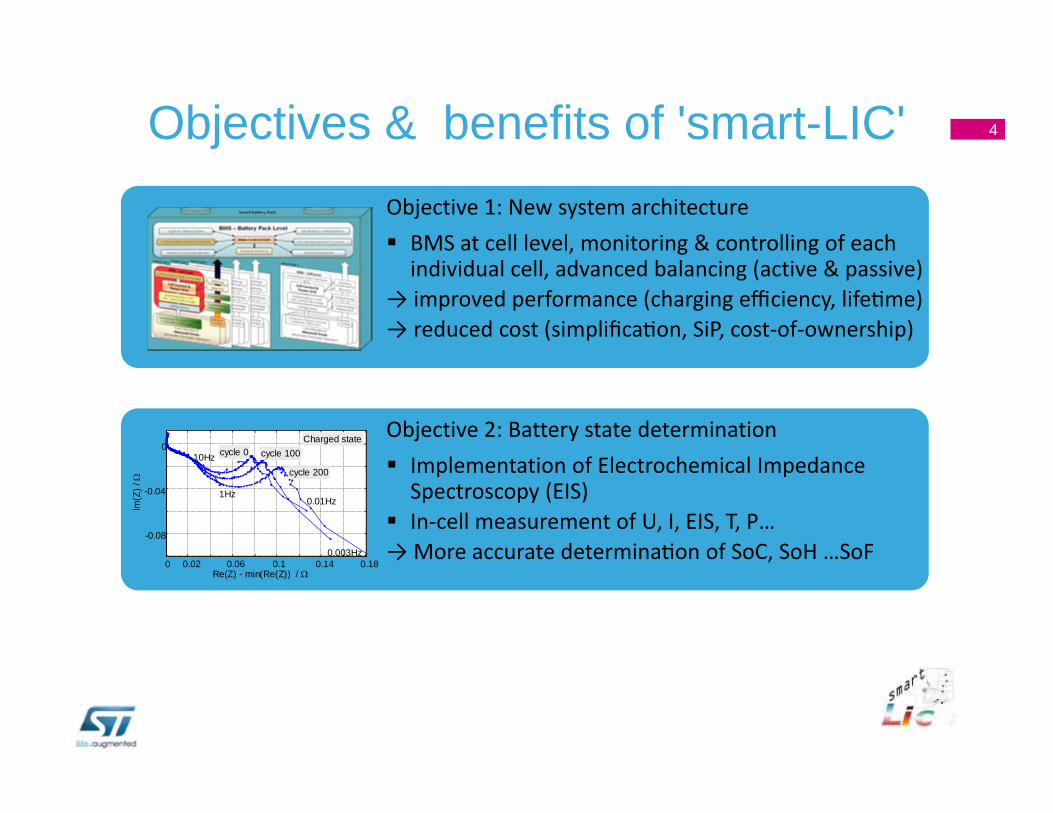
Objective 1: New system architecture BMS at cell level, monitoring & controlling of each individual cell, advanced balancing (active & passive)
→ improved performance (charging efficiency, life me) → reduced cost (simplifica on, SiP, cost‐of‐ownership)
Objectives & benefits of 'smart-LIC'
Objective 2: Battery state determination Implementation of Electrochemical Impedance Spectroscopy (EIS)
In‐cell measurement of U, I, EIS, T, P…→ More accurate determina on of SoC, SoH …SoF
0 0.02 0.06 0.1 0.14 0.18
-0.08
-0.04
0
Re(Z) - min(Re(Z)) /
Im(Z
) /
10Hz
0.003Hz
0.01Hz1Hz
cycle 0 cycle 100
cycle 200
Charged state
4
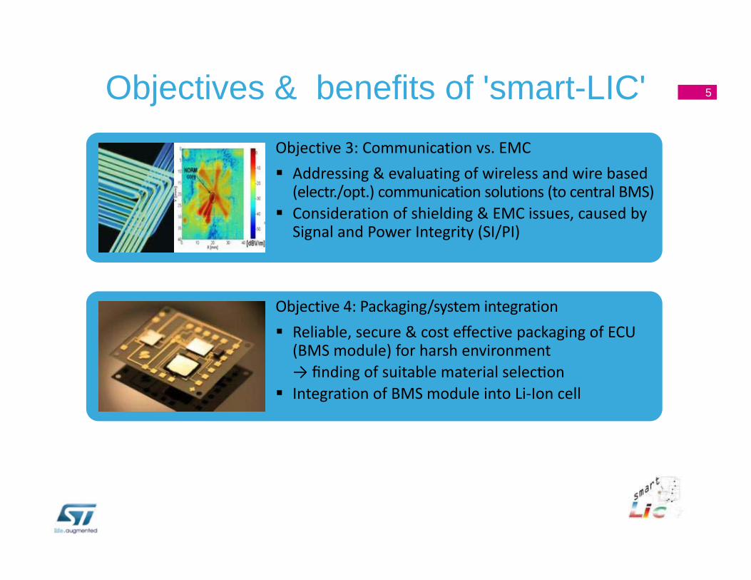
Objective 3: Communication vs. EMC Addressing & evaluating of wireless and wire based (electr./opt.) communication solutions (to central BMS)
Consideration of shielding & EMC issues, caused by Signal and Power Integrity (SI/PI)
Objectives & benefits of 'smart-LIC'
Objective 4: Packaging/system integration Reliable, secure & cost effective packaging of ECU (BMS module) for harsh environment→ finding of suitable material selec on
Integration of BMS module into Li‐Ion cell
5
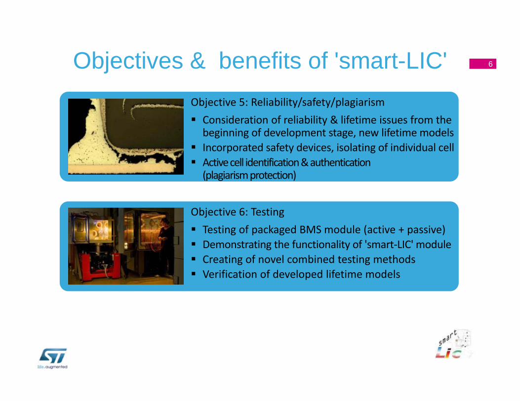
Objective 5: Reliability/safety/plagiarism Consideration of reliability & lifetime issues from the beginning of development stage, new lifetime models
Incorporated safety devices, isolating of individual cell Active cell identification & authentication (plagiarism protection)
Objectives & benefits of 'smart-LIC'
Objective 6: Testing Testing of packaged BMS module (active + passive) Demonstrating the functionality of 'smart‐LIC' module Creating of novel combined testing methods Verification of developed lifetime models
6
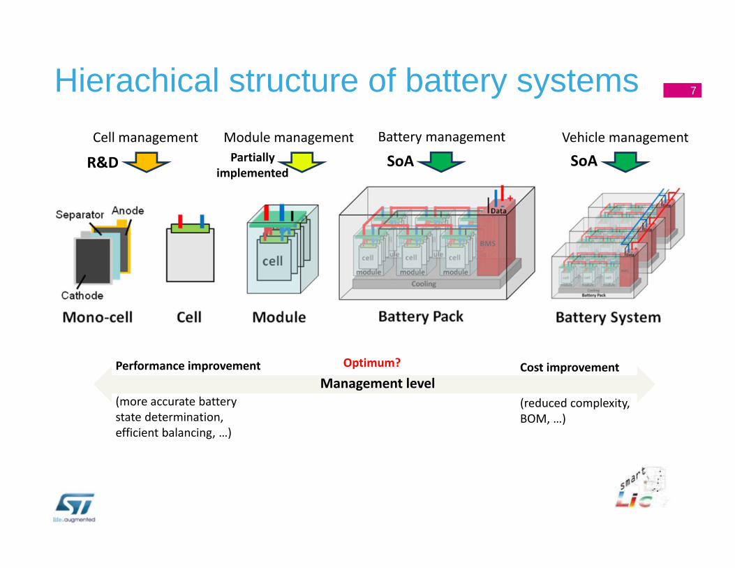
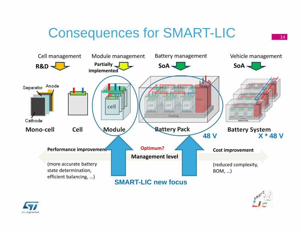
Vehicle management
SoABattery management
SoAModule managementPartially
implemented
Cell management
R&D
Management levelPerformance improvement
(more accurate battery state determination, efficient balancing, …)
Cost improvement
(reduced complexity, BOM, …)
Optimum?
7Hierachical structure of battery systems
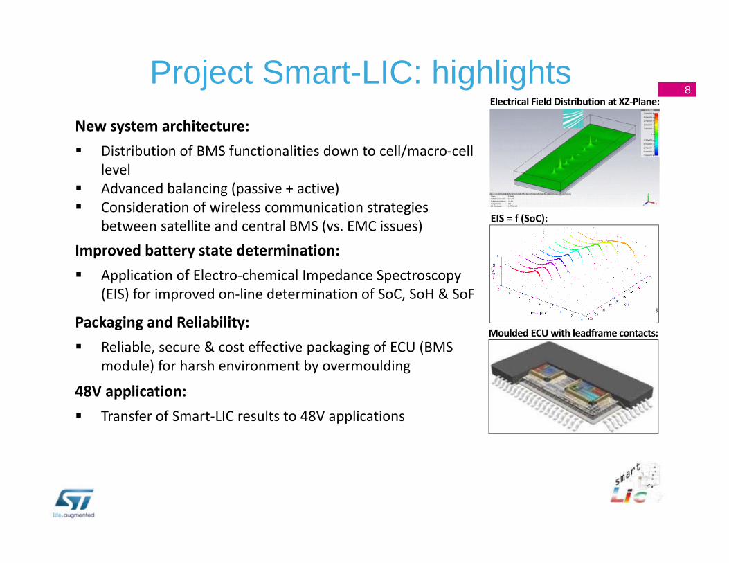
New system architecture: Distribution of BMS functionalities down to cell/macro‐cell
level Advanced balancing (passive + active) Consideration of wireless communication strategies
between satellite and central BMS (vs. EMC issues)
Improved battery state determination: Application of Electro‐chemical Impedance Spectroscopy
(EIS) for improved on‐line determination of SoC, SoH & SoF
48V application: Transfer of Smart‐LIC results to 48V applications
Packaging and Reliability: Reliable, secure & cost effective packaging of ECU (BMS
module) for harsh environment by overmoulding
Moulded ECU with leadframe contacts:
Electrical Field Distribution at XZ‐Plane:
EIS = f (SoC):
8Project Smart-LIC: highlights
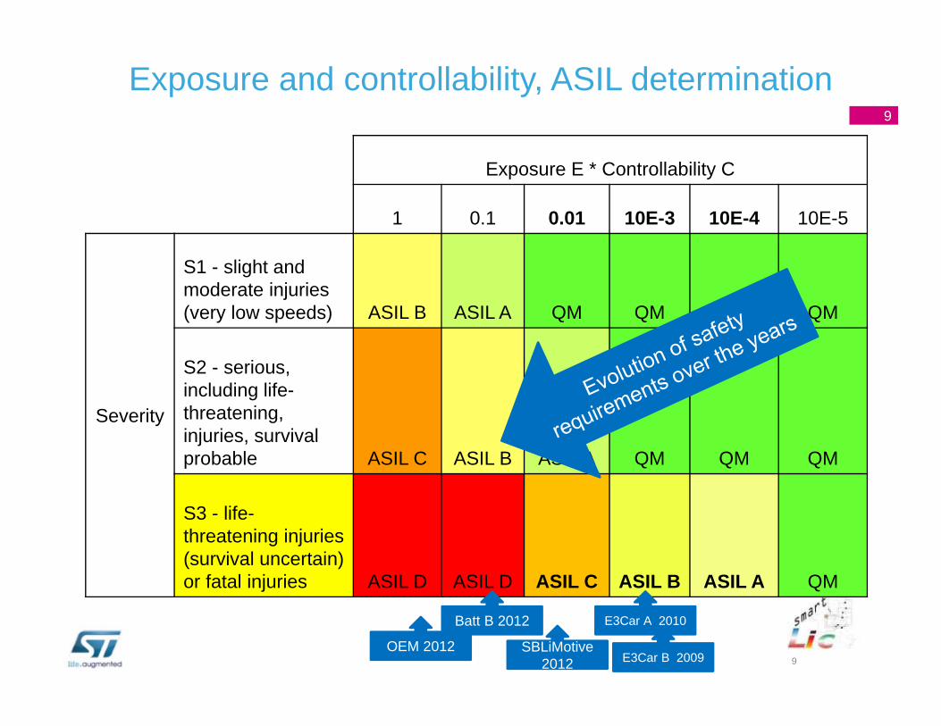
9
Exposure E * Controllability C
1 0.1 0.01 10E-3 10E-4 10E-5
Severity
S1 - slight and moderate injuries(very low speeds) ASIL B ASIL A QM QM QM QM
S2 - serious, including life-threatening, injuries, survival probable ASIL C ASIL B ASIL A QM QM QM
S3 - life-threatening injuries (survival uncertain) or fatal injuries ASIL D ASIL D ASIL C ASIL B ASIL A QM
SBLiMotive2012
E3Car A 2010
E3Car B 2009OEM 2012
Batt B 2012
Exposure and controllability, ASIL determination9
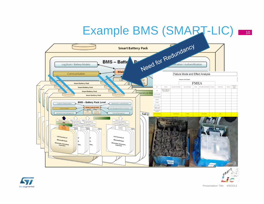
Example BMS (SMART-LIC) 10
4/9/2013Presentation Title
2012 2025
5% passive balancing
Costs for OEM 1 with active balancing system12%…15%
BatteryCost/KWh
280 €
400 €Assumption:Typical EV battery: 20 KWh= 8000 € 5600 €
AB = 1000 €PB = 400 €
AB = 700 € to 588 €* PB = 280 € to 235 €*
*) With productivity 4% / year (imposed by Car Maker) :
Cost Benchmarking Smart-LIC compared to active and passive balancing solutions
(estimation by O. Wyman, 2012)
Smart-LICFrom 1100 to 600
Smart-LIC15 to 20 %
OEM 2 target: 1 to 2%
What is the cost benefit of a better BMS ?How to make the optimum BMS (price/performance ratio ?)
11
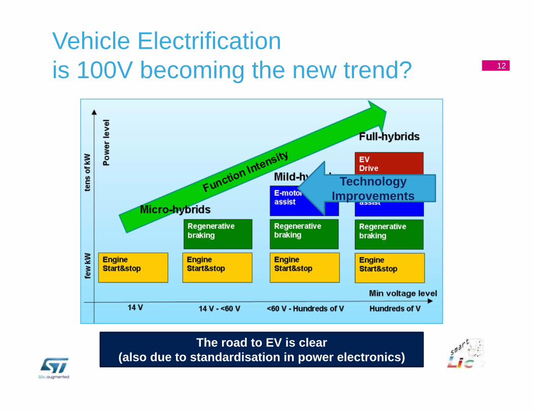
Vehicle Electrificationis 100V becoming the new trend?
12
The road to EV is clear(also due to standardisation in power electronics)
TechnologyImprovements
12
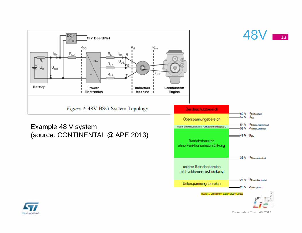
48V 13
4/9/2013Presentation Title
Example 48 V system(source: CONTINENTAL @ APE 2013)
Vehicle management
SoABattery management
SoAModule managementPartially
implemented
Cell management
R&D
Management levelPerformance improvement
(more accurate battery state determination, efficient balancing, …)
Cost improvement
(reduced complexity, BOM, …)
Optimum?
14Consequences for SMART-LIC
48 V X * 48 V
SMART-LIC new focus
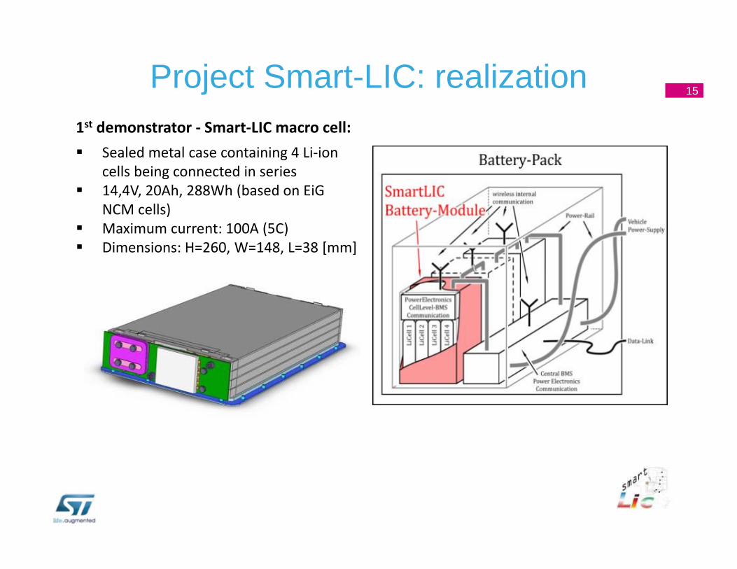
1st demonstrator ‐ Smart‐LIC macro cell: Sealed metal case containing 4 Li‐ion
cells being connected in series 14,4V, 20Ah, 288Wh (based on EiG
NCM cells) Maximum current: 100A (5C) Dimensions: H=260, W=148, L=38 [mm]
15Project Smart-LIC: realization
Power module:based on DCB substrate
Smart‐LIC macro‐cell
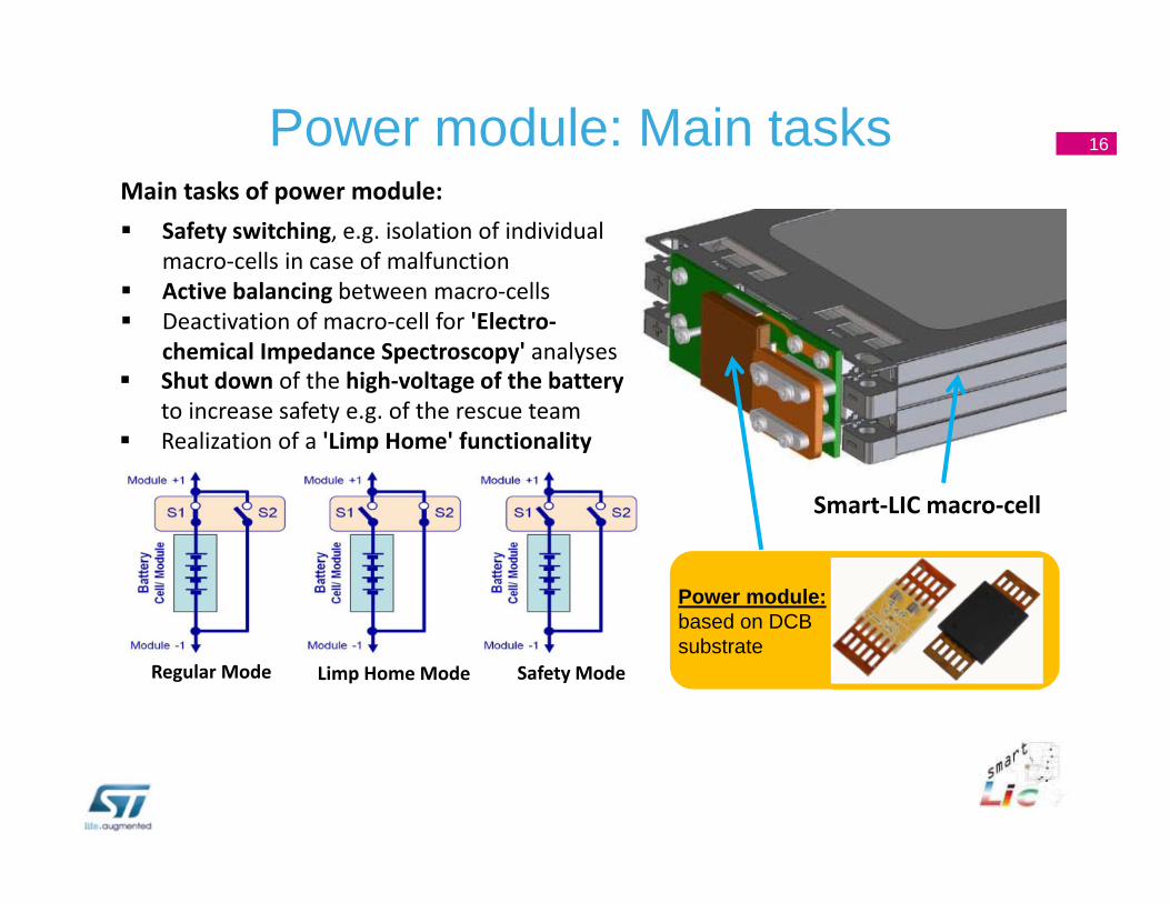
Regular Mode Limp Home Mode Safety Mode
Main tasks of power module: Safety switching, e.g. isolation of individual
macro‐cells in case of malfunction Active balancing between macro‐cells Deactivation of macro‐cell for 'Electro‐
chemical Impedance Spectroscopy' analyses Shut down of the high‐voltage of the battery
to increase safety e.g. of the rescue team Realization of a 'Limp Home' functionality
16Power module: Main tasks
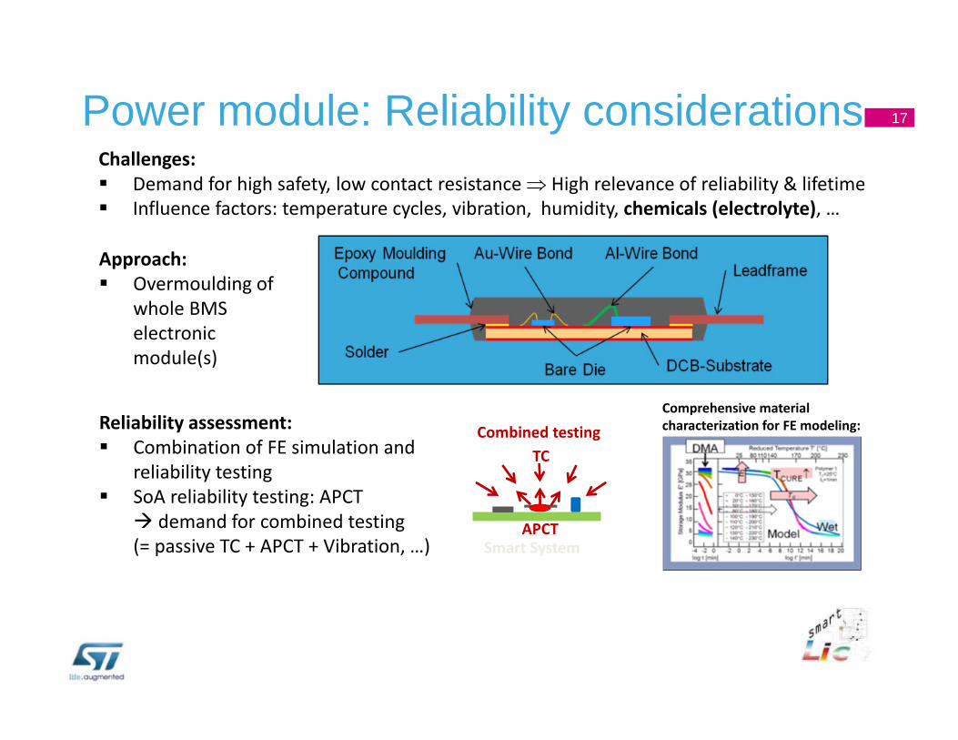
Challenges: Demand for high safety, low contact resistance High relevance of reliability & lifetime Influence factors: temperature cycles, vibration, humidity, chemicals (electrolyte), …
Approach: Overmoulding of
whole BMS electronic module(s)
Reliability assessment: Combination of FE simulation and
reliability testing SoA reliability testing: APCT demand for combined testing (= passive TC + APCT + Vibration, …)
Comprehensive material characterization for FE modeling:
Smart System
Combined testingTC
APCT
17Power module: Reliability considerations
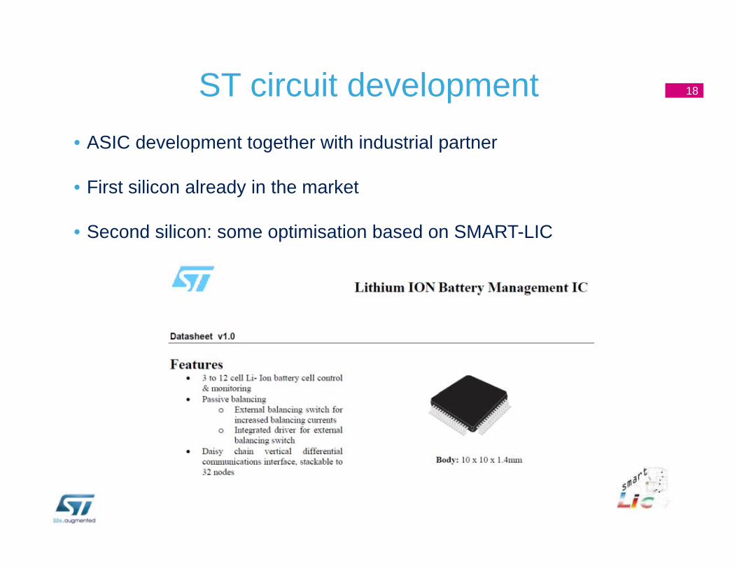
ST circuit development• ASIC development together with industrial partner
• First silicon already in the market
• Second silicon: some optimisation based on SMART-LIC
18
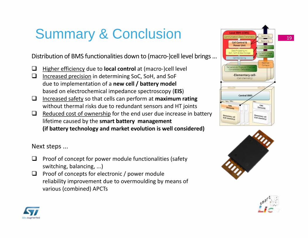
Distribution of BMS functionalities down to (macro‐)cell level brings ...
Higher efficiency due to local control at (macro‐)cell level Increased precision in determining SoC, SoH, and SoF
due to implementation of a new cell / battery model based on electrochemical impedance spectroscopy (EIS)
Increased safety so that cells can perform at maximum ratingwithout thermal risks due to redundant sensors and HT joints
Reduced cost of ownership for the end user due increase in battery lifetime caused by the smart battery management(if battery technology and market evolution is well considered)
Next steps ...
Proof of concept for power module functionalities (safety switching, balancing, ...)
Proof of concepts for electronic / power module reliability improvement due to overmoulding by means of various (combined) APCTs
19Summary & Conclusion