Embed Size (px)
Citation preview
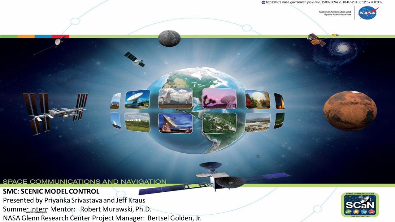
SMC: SCENIC MODEL CONTROLPresented by Priyanka Srivastava and Jeff KrausSummer Intern Mentor: Robert Murawski, Ph.D.NASA Glenn Research Center Project Manager: Bertsel Golden, Jr.
https://ntrs.nasa.gov/search.jsp?R=20150023094 2018-07-23T06:12:57+00:00Z
Introduction-Synergy of Students
2
Presentation Agenda
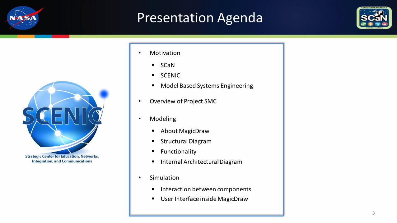
• Motivation
SCaN
SCENIC
Model Based Systems Engineering
• Overview of Project SMC
• Modeling
About MagicDraw
Structural Diagram
Functionality
Internal Architectural Diagram
• Simulation
Interaction between components
User Interface inside MagicDraw
3
Space Communication and Navigation (SCaN)
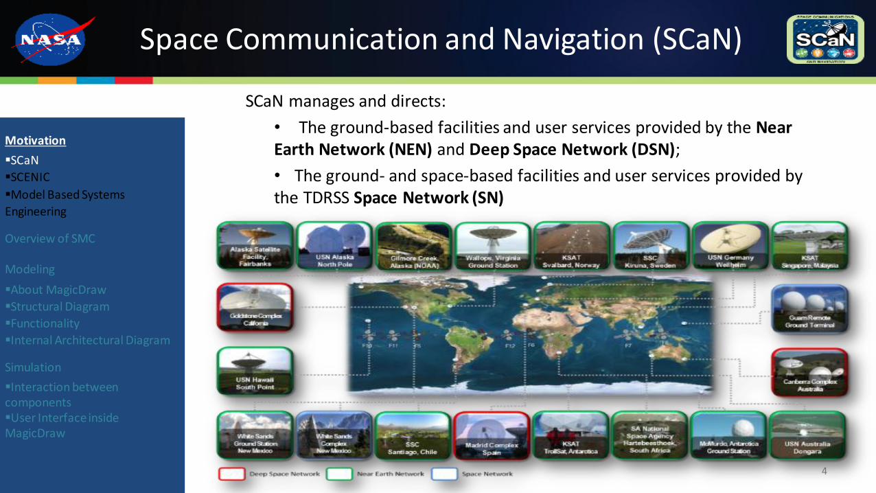
SCaN manages and directs:
• The ground-based facilities and user services provided by the Near Earth Network (NEN) and Deep Space Network (DSN);
• The ground- and space-based facilities and user services provided by the TDRSS Space Network (SN)
4
Motivation
SCaN
SCENIC
Model Based Systems
Engineering
Overview of SMC
Modeling
About MagicDraw
Structural Diagram
Functionality
Internal Architectural Diagram
Simulation
Interaction between componentsUser Interface inside MagicDraw
Space Communications and Navigation (SCaN) (continued)
SCaN future objectives:
• Integration of existing NASA SCaN assets, building a single NASA-wide space communications and navigation network;
• Implementation of data communication protocols for Space Exploration missions that are internationally interoperable.
• Meets the future needs and commitments to provide space communications and navigation services to missions.
5
Motivation
SCaN
SCENIC
Model Based Systems
Engineering
Overview of SMC
Modeling
About MagicDraw
Structural Diagram
Functionality
Internal Architectural Diagram
Simulation
Interaction between componentsUser Interface inside MagicDraw
Strategic Center for Education, Networks, Integration and Communications (SCENIC) Lab
SCENIC Mission Statement: Provide a strategic center for education, networks, integration, and communications to collaboratively define and address the needs of future NASA communications.
Modeling and Analysis Goals
• Development of current SCaN Network models that are expandable, verifying proposed future architectures;
• Capacity Modeling of the existing and future SCaN Networks;
• Simulation of the network communication and navigation infrastructure space and ground networks.
6
Motivation
SCaN
SCENIC
Model Based Systems
Engineering
Overview of SMC
Modeling
About MagicDraw
Structural Diagram
Functionality
Internal Architectural Diagram
Simulation
Interaction between componentsUser Interface inside MagicDraw
Why Model-Based Systems Engineering?
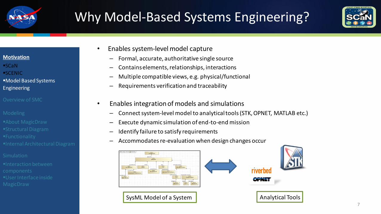
• Enables system-level model capture
– Formal, accurate, authoritative single source
– Contains elements, relationships, interactions
– Multiple compatible views, e.g. physical/functional
– Requirements verification and traceability
• Enables integration of models and simulations
– Connect system-level model to analytical tools (STK, OPNET, MATLAB etc.)
– Execute dynamic simulation of end-to-end mission
– Identify failure to satisfy requirements
– Accommodates re-evaluation when design changes occur
7
Motivation
SCaN
SCENIC
Model Based Systems
Engineering
Overview of SMC
Modeling
About MagicDraw
Structural Diagram
Functionality
Internal Architectural Diagram
Simulation
Interaction between componentsUser Interface inside MagicDraw
SysML Model of a System Analytical Tools
SCENIC Model Control (SMC)
Project Mission:
To develop a SCaN network model with its architectural elements in an evolutionary and expandable format. SMC is a framework utilizing a modular approach with MagicDraw as the primary User Interface Software.
SMC Task Objectives:
• Model SCaN ground networks and desired user missions in SysML
• Perform capacity modeling and coverage analysis of SCaN Network assets based on SCaN Mission Loading.
• Integrate the developed tools and wrappers thru a custom MagicDraw User Interface.
• Development of a Control Module which facilitates transfer of model information and generated reports via custom XML communication schema.
8
Motivation
SCaN
SCENIC
Model Based Systems
Engineering
Overview of SMC
Modeling
About MagicDraw
Structural Diagram
Functionality
Internal Architectural
Diagram
Simulation
Interaction between componentsUser Interface inside MagicDraw
SMC Capacity Modeling Tools
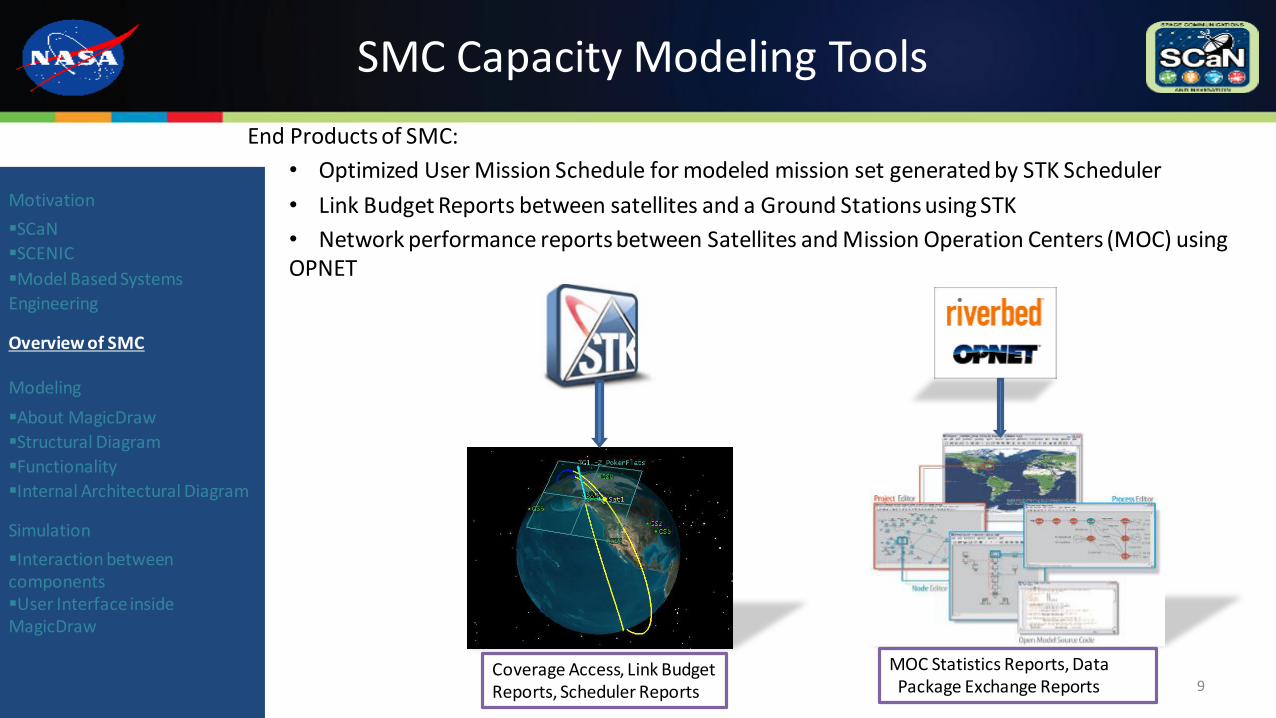
End Products of SMC:
• Optimized User Mission Schedule for modeled mission set generated by STK Scheduler
• Link Budget Reports between satellites and a Ground Stations using STK
• Network performance reports between Satellites and Mission Operation Centers (MOC) using OPNET
9
Motivation
SCaN
SCENIC
Model Based Systems
Engineering
Overview of SMC
Modeling
About MagicDraw
Structural Diagram
Functionality
Internal Architectural Diagram
Simulation
Interaction between componentsUser Interface inside MagicDraw
Coverage Access, Link BudgetReports, Scheduler Reports
MOC Statistics Reports, DataPackage Exchange Reports
Modeling SMC
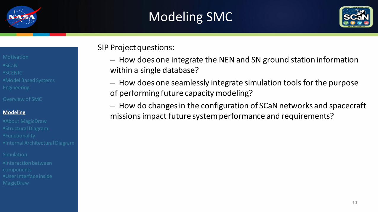
SIP Project questions:
– How does one integrate the NEN and SN ground station information within a single database?
– How does one seamlessly integrate simulation tools for the purpose of performing future capacity modeling?
– How do changes in the configuration of SCaN networks and spacecraft missions impact future system performance and requirements?
10
Motivation
SCaN
SCENIC
Model Based Systems
Engineering
Overview of SMC
Modeling
About MagicDraw
Structural Diagram
Functionality
Internal Architectural Diagram
Simulation
Interaction between componentsUser Interface inside MagicDraw
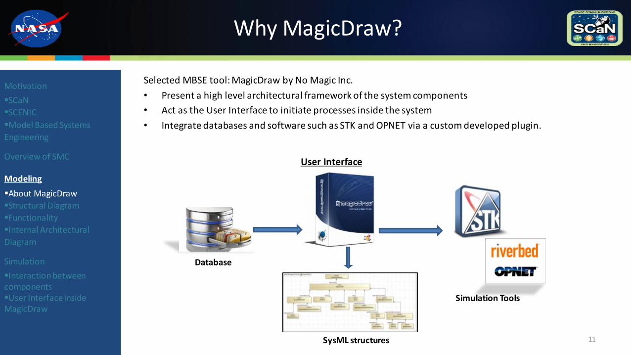
Why MagicDraw?
Selected MBSE tool: MagicDraw by No Magic Inc.
• Present a high level architectural framework of the system components
• Act as the User Interface to initiate processes inside the system
• Integrate databases and software such as STK and OPNET via a custom developed plugin.
11
Motivation
SCaN
SCENIC
Model Based Systems
Engineering
Overview of SMC
Modeling
About MagicDraw
Structural Diagram
Functionality
Internal Architectural
Diagram
Simulation
Interaction between componentsUser Interface inside MagicDraw
Database
SysML structures
User Interface
Simulation Tools
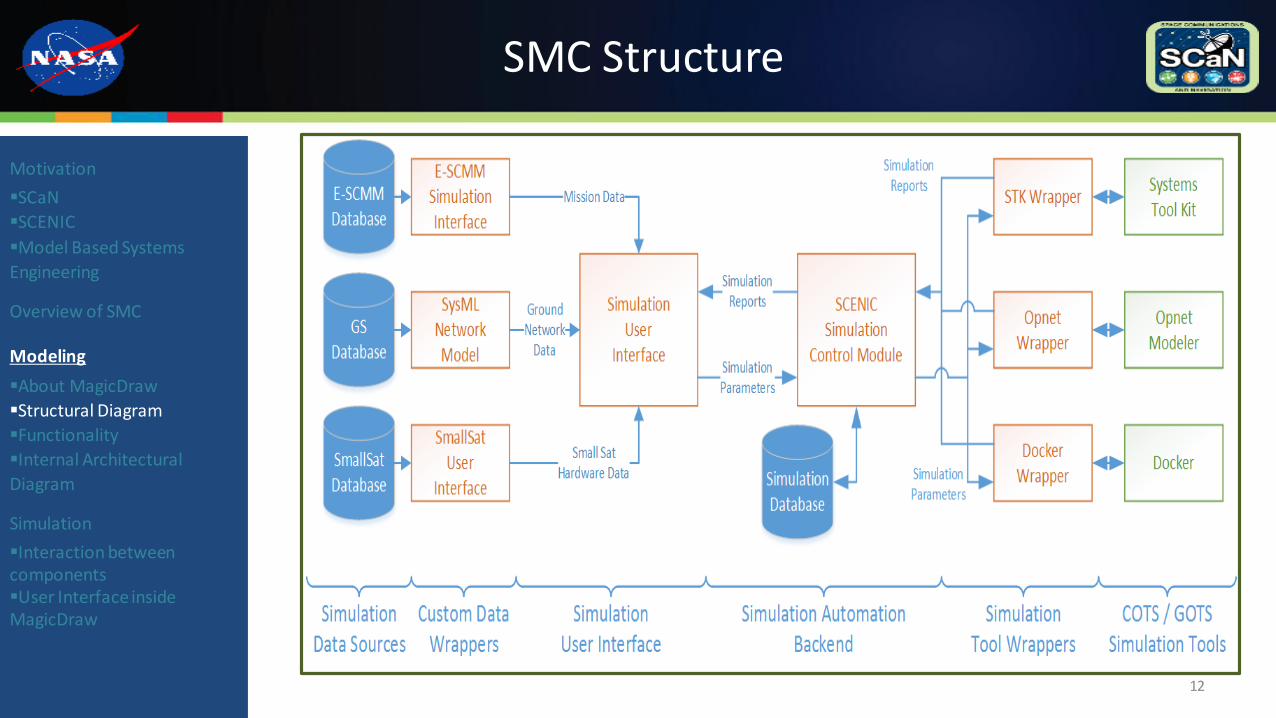
SMC Structure
12
Motivation
SCaN
SCENIC
Model Based Systems
Engineering
Overview of SMC
Modeling
About MagicDraw
Structural Diagram
Functionality
Internal Architectural
Diagram
Simulation
Interaction between componentsUser Interface inside MagicDraw
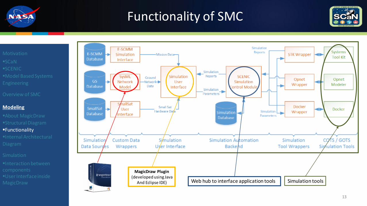
Functionality of SMC
13
Motivation
SCaN
SCENIC
Model Based Systems
Engineering
Overview of SMC
Modeling
About MagicDraw
Structural Diagram
Functionality
Internal Architectural
Diagram
Simulation
Interaction between componentsUser Interface inside MagicDraw
MagicDraw Plugin(developed using Java
And Eclipse IDE) Web hub to interface application tools Simulation tools
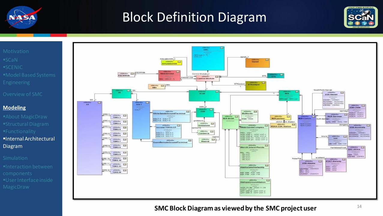
Block Definition Diagram
14
Motivation
SCaN
SCENIC
Model Based Systems
Engineering
Overview of SMC
Modeling
About MagicDraw
Structural Diagram
Functionality
Internal Architectural
Diagram
Simulation
Interaction between componentsUser Interface inside MagicDraw
SMC Block Diagram as viewed by the SMC project user
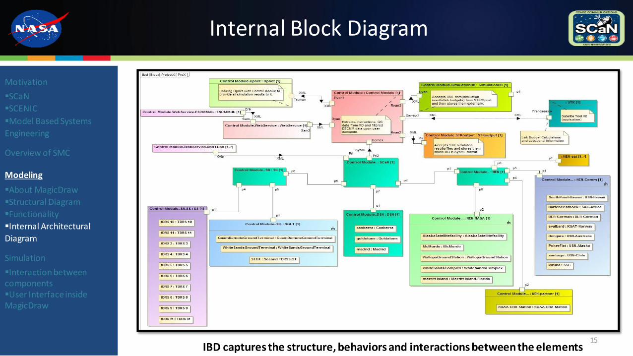
Internal Block Diagram
15
Motivation
SCaN
SCENIC
Model Based Systems
Engineering
Overview of SMC
Modeling
About MagicDraw
Structural Diagram
Functionality
Internal Architectural
Diagram
Simulation
Interaction between componentsUser Interface inside MagicDraw
IBD captures the structure, behaviors and interactions between the elements
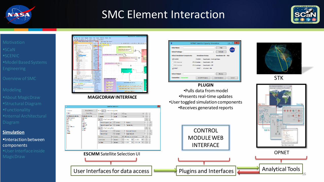
SMC Element Interaction
16
Motivation
SCaN
SCENIC
Model Based Systems
Engineering
Overview of SMC
Modeling
About MagicDraw
Structural Diagram
Functionality
Internal Architectural
Diagram
Simulation
Interaction between componentsUser Interface inside MagicDraw
CONTROL MODULE WEB
INTERFACE
User Interfaces for data access Analytical ToolsPlugins and Interfaces
OPNET
STKPLUGIN
•Pulls data from model•Presents real-time updates
•User toggled simulation components•Receives generated reports
MAGICDRAW INTERFACE
ESCMM Satellite Selection UI
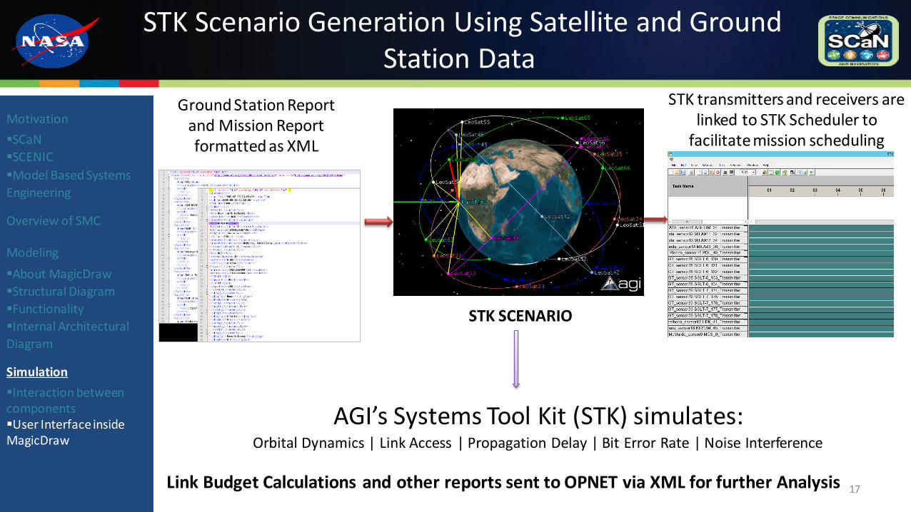
STK Scenario Generation Using Satellite and Ground Station Data
17
Motivation
SCaN
SCENIC
Model Based Systems
Engineering
Overview of SMC
Modeling
About MagicDraw
Structural Diagram
Functionality
Internal Architectural
Diagram
Simulation
Interaction between componentsUser Interface inside MagicDraw
AGI’s Systems Tool Kit (STK) simulates:Orbital Dynamics | Link Access | Propagation Delay | Bit Error Rate | Noise Interference
Link Budget Calculations and other reports sent to OPNET via XML for further Analysis
Ground Station Report and Mission Report formatted as XML
STK SCENARIO
STK transmitters and receivers are linked to STK Scheduler to
facilitate mission scheduling
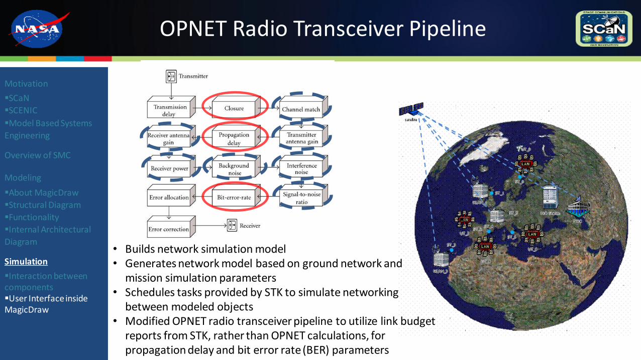
OPNET Radio Transceiver Pipeline
Motivation
SCaN
SCENIC
Model Based Systems
Engineering
Overview of SMC
Modeling
About MagicDraw
Structural Diagram
Functionality
Internal Architectural
Diagram
Simulation
Interaction between componentsUser Interface inside MagicDraw
• Builds network simulation model• Generates network model based on ground network and
mission simulation parameters• Schedules tasks provided by STK to simulate networking
between modeled objects• Modified OPNET radio transceiver pipeline to utilize link budget
reports from STK, rather than OPNET calculations, for propagation delay and bit error rate (BER) parameters
Questions / Comments / Snide Remarks?
19