Embed Size (px)
Citation preview
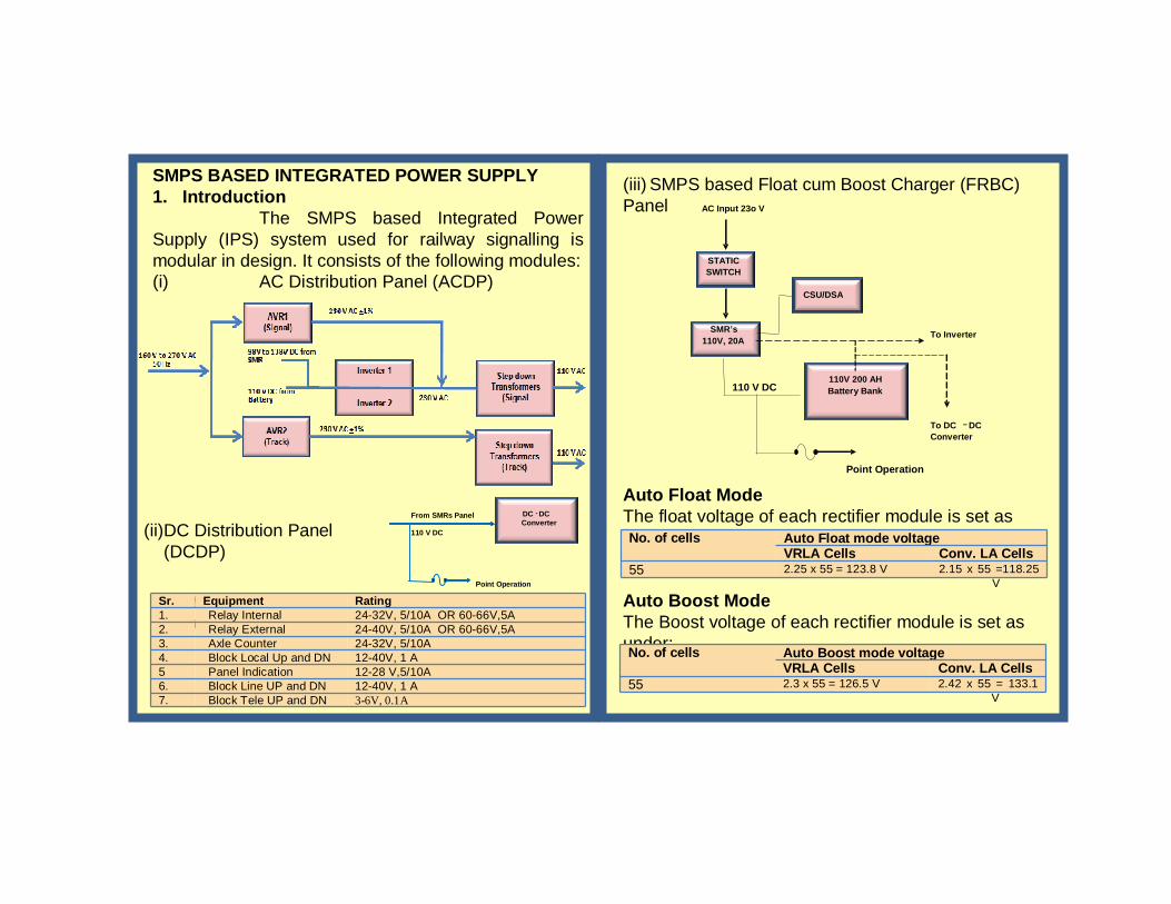
SMPS BASED INTEGRATED POWER SUPPLY1. Introduction
The SMPS based Integrated Power Supply (IPS) system used for railway signalling is modular in design. It consists of the following modules:(i) AC Distribution Panel (ACDP)
(ii)DC Distribution Panel (DCDP)
Outputs of DC-DC converter
Sr. Equipment Rating1. Relay Internal 24-32V, 5/10A OR 60-66V,5A2. Relay External 24-40V, 5/10A OR 60-66V,5A3. Axle Counter 24-32V, 5/10A4. Block Local Up and DN 12-40V, 1 A5 Panel Indication 12-28 V,5/10A6. Block Line UP and DN 12-40V, 1 A7. Block Tele UP and DN 3-6V, 0.1A
(iii) SMPS based Float cum Boost Charger (FRBC) Panel
Auto Float ModeThe float voltage of each rectifier module is set as under:No. of cells Auto Float mode voltage
VRLA Cells Conv. LA Cells55 2.25 x 55 = 123.8 V 2.15 x 55 =118.25
V
Auto Boost ModeThe Boost voltage of each rectifier module is set as under:No. of cells Auto Boost mode voltage
VRLA Cells Conv. LA Cells55 2.3 x 55 = 126.5 V 2.42 x 55 = 133.1
V
DC - DC Converter
Point Operation
From SMRs Panel
110 V DC
STATICSWITCH
SMR’s110V, 20A
110V 200 AH Battery Bank
Point Operation
To Inverter
To DC – DC Converter
110 V DC
AC Input 23o V
CSU/DSA

Indications on Front Panels
•DC-DC Converter
F U S E
AC INPUT ON
OFF
OUT PUT VOLTAGE L N
FAN FAIL
INPUT ON
OUTPUT ON INVERTER FAIL
LOAD ON INVERTER
START
STOP
RESET • Automatic Voltage Regulator
Fuse
AC INPUT 32A, 415 V AC
OUT PUT ON
OUT PUT FAIL AC volts test INPUT ON points
L N
• Step Down Transformer • Switch mode Rectifier
Maintenance Check points1. DCDP•Check O/P voltage of each DC-DC Converter on DCDP common digital voltmeter
• Adjustment of Converter output voltage:o Pull DC-DC Converter from front. o Connect test points to Common Digital Voltmeter
• Inverter

o Adjust potentiometer to get the desired output
• Parallel check of converters:
oSwitch off one converter with ON/OFF switch.
oObserve output of other converters in parallel sharing the load.
2. ACDP•Check O/P voltage current of inverters , AVRs and step down transformers with on digital voltmeter provided on ACDP.
• Ensure auto change over between inverter 1 and 2 by On/Off MCB.
• Check auto change over between inverters and AVRs.
• Ensure all the connectors of subsystems are inserted properly.

Battery Maintenance•Cleaning of all cells near its terminals periodically.•Reading of all cell’s voltage with Charger ON and Charger OFF.•Boosting of Sick cell using Sick cell Charger.•Applying petroleum jelly over the terminals for LMLA batteries.•Periodically recording specific gravity of all cells.•Periodically checking of electrolytic level of cells.•Boosting of Sick cell using Sick cell Charger.•Battery room should be properly ventilated.•Connect the polarity of the batteries in right position.
Disclaimer
The information given in this pamphlet does not supersede any existing provisions laid down in S.E.M., Rly. Board and RDSO publications. This document is not statutory and instructions given in it are for the purpose of guidance only. If at any point contradiction is observed, then S.E.M., Rly. Board/RDSO guidelines or Zonal Rly. instructions may be
followed.
::Contact Address::Indian Railways
Centre for Advanced Maintenance Technology
Maharajpur, Gwalior – 474 005Email: [email protected]
GOVERNMENT OF INDIA GOVERNMENT OF INDIA MINISTRY OF RAILWAYS MINISTRY OF RAILWAYS
MAINTENANCE OF MAINTENANCE OF SMPS BASED INTEGRATED POWER SMPS BASED INTEGRATED POWER
SUPPLYSUPPLY
CAMTECH/S/2010/IPS/1.0 June 2010
(For Official Use)
+ - -
--
++ +
+ -
- - - -