Embed Size (px)
Citation preview

Solid DielectricSwitchgear
Providing load and fault interrupting switchingfor systems rated through 38kV, 800A
continuous, 12.5kA symmetrical interrupting
• Submersible vault designs• Dead-front padmount designs• Time proven, solid epoxy
insulation• Modular construction• Maintenance-free operation• Ease of automation• Lazer TM ready
CATALOG GW5-TS09MARCH, 2009
Engineered to OrderBuilt to Last
6640_Trident 09.qxd:Trident 28pgr 3/16/09 9:50 AM Page 1

WORLDWIDE EXPERIENCEAND PERFORMANCESince 1905, G&W has been provid-ing custom electrical products andinnovative solutions to power usersaround the world. Today, G&Wcontinues that tradition with a fullline of solid dielectric switchgearusing the industry’s latest insulationtechnology. Trident switchgearcombines the best solid dielectricinsulation materials with timeproven, rugged, and reliableswitching designs. Drawing onmany years of field experience inthe areas of load break switchingand vacuum fault interrupter tech-nology, G&W offers one of thewidest selections of electrical distri-bution switchgear in the industry.
SOLID DIELECTRICTECHNOLOGYTrident switchgear utilizes G&W’stime proven, submersible epoxypolymer system to fully encapsulatethe vacuum interrupters. This sys-tem provides excellent insulationproperties and incorporates a per-manently bonded semi-conductiveexternal coating providing a fullyshielded, void-free construction.Internal shields limit the electricalstress in the epoxy, thereforeincreasing its electrical integrity. Allmodules are UV protected and100% factory tested for partial dis-charge. Dual ratio current transform-ers are encapsulated within eachmodule providing either 500:1 or1000:1 protection characteristics.
SUBMERSIBILITYSolid dielectric switchgear is dead-front and fully submersible. Unitshave remained fully operable afterwithstanding a 20 foot head ofwater for 20 days.
MAINTENANCE BENEFITSSolid dielectric insulation means nomore routine maintenance as with
oil and air switchgear. Solid dielec-tric insulation also offers an alterna-tive to gas insulated devices.
APPLICATION FLEXIBILITYSolid dielectric switchgear offerscompact, modular construction.Module configurations permitelbow style connections to be allfront mounted or front/back mount-ed depending on user preferrence.The same size modules can func-tion as either load break or faultinterrupting. Three phase switchescan be linked together to create tai-lored multi-way switch configura-tions. Trident fault interrupters offera wide variety of electronic overcur-rent controls for customized systemprotection coordination.Automation is easy whether it is anautomatic transfer scheme or a
fully integrated distribution automa-tion “Smart Grid” project.
IDEAL REPLACEMENT FOROIL FUSE CUTOUTSTrident fault interrupters are anideal replacement for single phaseor three phase oil fuse cutouts byoffering the following advantages:
• No more fuse links to stock or replace
• Maintenance-free, nonflammable solid dielectric insulation
• Positive load break operation andeasy reset of tripped circuits
• Electronic controls mirror fuse link curves
• Easy to automate
• 200A well or 600A separable connector bushing
FULLY TESTEDTrident switches are designed andtested to applicable standardsincluding IEEE C37.74 (IEEEC37.71 and C37.72), IEEE 386,IEC 60265, IEEE 592 and ANSI57.12.28. All fault interrupterdevices must pass recloser-classduties as outlined in IEEE C37.60.
Page 2
GENERAL FEATURES
INDEX
General Features ..........Page 2
Three Phase Designs ....Page 4
Multi-Way Designs ......Page 12
Single Phase Design ..Page 17
Accessories/Options ....Page 20
Specifications ............Page 25
Three phase Trident-S fault interrupters in a submersible vault application.
6640_Trident 09.qxd:Trident 28pgr 3/16/09 9:50 AM Page 2

OPERATING MECHANISMFLEXIBILITYTrident-SP, S and ST switchesincorporate integral single phase orthree phase spring-assisted mech-anisms for positive open and closeoperations. The operating mecha-nisms are located within a weldedstainless steel, air insulated hous-ing constructed to withstand conti-nous submersible environments.The spring mechanisms operatethe vacuum interrupters encapsu-lated within the epoxy modules toaccomplish load break switchingand fault interrupting protection.
Trident-SR switches incorporate aninternal magnetic actuator in placeof the spring-assisted mechanism,providing high speed operation.The magnetic actuator eliminatesthe need for add-on externalmotors and cabling making it anideal solution for automated switch-ing applications.
CABLE ENTRANCEFLEXIBILITYCable entrances can be either200A well or 600A separable con-nector bushings for acceptingelbow style connectors. Therugged epoxy surface minimizesthe force required for removingelbow connections compared torubber-to-rubber junctions.Different module orientations permitcable entry from the front, side,bottom or back of the unit.
INTERRUPTER CONTROLFLEXIBILITYTrident switchgear offers a varietyof overcurrent controls includingmany Schweitzer EngineeringLaboratories (SEL) models for faultinterrupting switches to suit mostany protection requirement. AllG&W controls are self-poweredfrom the integral CTs and offer over30 different TCC curve families.Certain models have inrushrestraint, ground fault protection,and manual trip pushbuttons.
Others may be programmedthrough a laptop computer, or witha front panel interface. Tridentcontrols may be mounted within anexternal NEMA 4X (IP56) or 6P(IP67) enclosure, or within theswitch mechanism housing, elimi-nating the need for externalcabling. G&W can also integrateother manufacturer’s controlsdepending on user preference.
MOUNTING FLEXIBILITYTrident switchgear is suitable forsubmersible vault or padmountinstallations. They may be mountedvertically or horizontally, on a wall orfloor, and in any attitude. The smallfootprint is ideal for space restrictedapplications. Stainless steel mount-ing brackets are available for maxi-mum corrosion resistance. Parkingstands are available.
OPERATING HANDLEFLEXIBILITYVarious styles of operating handlesare available depending upon userpreference. Handles can beremovable or permanently fixed tothe switch. Handles can bestraight or angled providing thebest mechanical advantage foroperating personnel. Handles canbe located on the front or side ofthe switch. All are hookstick operable.
AUTOMATION FLEXIBILITYTrident switchgear is easily adapt-ed for automation requirements.From simple remote controlthrough sophisticated distributionautomation schemes, G&W has theproducts and integration expertiseto do the job.
THE FLEXIBILITY OF SOLID DIELECTRIC TECHNOLOGY
“C” Module - Front access
“Z” Module -Front / backaccess
“L” Module -Front / bottomaccess
- Spring-assisted or magnetic actuator operation
- Submersible, welded construction
- Operating handle options
- Cable entrance options
Page 3
6640_Trident 09.qxd:Trident 28pgr 3/16/09 9:50 AM Page 3

TRIDENT®-S THREE PHASE SWITCHGEAR
Fault interrupter with wall mountedcontrol box and side mounted operatinghandle.
Trident-S three phase, spring-assisted switchgear is availablefor load break or fault interruptingswitching. The Trident-S is idealfor three phase distribution switch-ing and protection, as well as forthree phase oil fuse cutout and oilswitchgear replacements. Faultprotection can be provided usingvacuum interrupters with integralCTs and a variety of overcurrentcontrols.
FEATURES
• 15.5, 27, or 38kV, 800A continu-ous current
• 16kA symmetrical interrupting at 15.5kV, 12.5kA at 27 and 38kV
• Manual or automated operation
• Padmount and vault designs
• Vertical or horizontal mounting
• Hookstick operable with per-manent or removable handles
• Submersible construction
• Optional handle permitting switch to function as a load break or fault interrupter
Horizontal mounted fault interrupter in a submersible vault.
Padmount switch with horizontalmounting and diagonal, spreadbushing configuration.
Page 4
Front mounted motor
Viewing window - Closed (red),Open (green)
Side mounted handles can bepositioned with hookstick eyeon top or bottom for bestmechanical advantage.
Spring-assisted operatingmechanism
Switch from fault inter-rupting to load breakby just rotating a lever.
6640_Trident 09.qxd:Trident 28pgr 3/16/09 9:50 AM Page 4

41"(1042mm)
11"(279mm)(1245mm)
49"
ELECTRONIC CONTROL
41"(1035mm)
Padmount style , front access, horizontal mountApproximate DimensionsApproximate Weight = 700 lbs. (318 kg)Spread bushing configuration
Vault styleApproximate DimensionsApproximate Weight = 200 lbs. (91 kg)
Configuration ‘B’ with bushingsfront and handle front mounted.
14"(356mm)
18"(457mm)
31"(784mm)
Configuration ‘A’ with bushings frontand handle side mounted.
Page 5
18"(457mm)
24"(610mm)
30"(760mm)
13"(355mm)
6640_Trident 09.qxd:Trident 28pgr 3/16/09 9:50 AM Page 5

TRIDENT®-SR THREE PHASE SWITCHGEAR
Trident-SR, magnetic actuator,SCADA ready switches simplify theprocess of automated switchingand fault interruption on systemsrated through 38kV. The extremelyflexible design permits the user tocustomize the best solution for theirparticular application. From manualload break or fault interrupting, toremote operation, to fully automat-ed distribution automation or SmartGrid schemes, the Trident-SRoffers multiple application function-ality, all within the same compactswitch footprint. Compare thesefeatures:
FEATURES
• 15.5, 27, or 38kV, 800A continu-ous current
• 12.5kA symmetrical interrupting • Manual or automated operation• Padmount and vault designs• Vertical or horizontal mounting• Hookstick operable with front
mounted handles.
For load break switching - Therugged magnetic acutator is testedto over 10,000 mechanical loadbreak operations.
For fault interrupting - A varietyof Schweitzer EngineeringLaboratories (SEL) relays andG&W electronic controls are avail-able to best meet the specific pro-tection needs of the application.Programming using a laptop com-puter or built-in LCD display areavailable options. G&W controlsare powered by CTs housed withinthe epoxy module. Other style con-trols also available.
For remote operation - Hand heldremote operators are available per-mitting pushbutton operation fromeither above ground for vault appli-cations or from a control adjacentto the enclosure for padmountapplications.
Vault style Trident-SR with frontmounted bushings.
Page 6
High speed magneticactuator
Electronic circuitboards
Manual open handle
Drive rod
Viewing window
Manually controlledclose handle
Vacuum bottle
Encapsulated 200A well or600A separable connectorbushings for elbow connectors
Encapsulated currenttransformer and voltage sensing
6640_Trident 09.qxd:Trident 28pgr 3/16/09 9:50 AM Page 6
For SCADA ready automation - Current transformers encapsulatedwithin the epoxy modules provideintegral current sensing. Integralcapacitively coupled voltagescreens provide three phase ana-log voltage values for connection toa wide selection of relays and RTUs.
For LazerTM
ready automation -Trident-SR switches are an integralpart of G&W’s pre-engineeredLazer control package to provideautomatic power restoration. UsingSEL relays with distributed capabili-ties and peer-to-peer communica-tion, G&W’s Lazer solution withTrident switchgear can greatly sim-plify the automation process fromsmall scale through large scalesystem requirements.
For future Smart Grid - Thinkingof automating in the near future butneed switches now? The built-infeatures and application flexibility ofthe Trident-SR can help simplifyyour decision.
Magnetic actuator - Switchesincorporate an integral magnetic actuator for high speed operation.No external add-on motor or link-age is required for remote opera-tion or automation schemes.
Compact, clean design - No add-on motors or linkage. Noexternal CTs or voltage sensorshanging from elbow connectors.Trident-SR switches feature built-incomponents.
Maintenance benefits - Soliddielectric insulation eliminates anyconcern about liquid or gaseousdielectrics. That means no moreroutine switch maintenance.
Submersibility - Solid dielectricswitchgear is dead-front and fullysubmersible. Units have remainedfully operable after withstanding a20 foot head of water for 20 days.
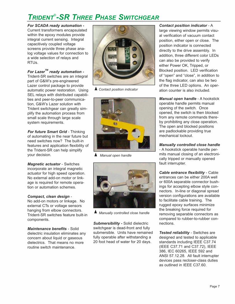
Contact position indicator - Alarge viewing window permits visu-al verification of vacuum contactposition, either open or close. Theposition indicator is connecteddirectly to the drive assembly. Inaddition, three different color LEDscan also be provided to verifyeither Power OK, Tripped, orBlocked position. LED verificationof “open” and “close”, in addition tothe flag indicator, can also be twoof the three LED options. An oper-ation counter is also included.
Manual open handle - A hookstickoperable handle permits manualopening of the switch. Onceopened, the switch is then blockedfrom any remote commands there-by prohibiting any close operation.The open and blocked positionsare padlockable providing truemechanical lockout.
Manually controlled close handle- A hookstick operable handle per-mits manual closing of an electroni-cally tripped or manually openedfault interrupter.
Cable entrance flexibility - Cableentrances can be either 200A wellor 600A separable connector bush-ings for accepting elbow style con-nectors. In-line or diagonal spreadversion configurations are availableto facilitate cable training. Therugged epoxy surfaces minimizethe breaking force required forremoving separable connectors ascompared to rubber-to-rubber con-nections.
Tested reliability - Switches aredesigned and tested to applicablestandards including IEEE C37.74(IEEE C37.71 and C37.72), IEEE386, IEC 60265, IEEE 592 andANSI 57.12.28. All fault interrupterdevices pass recloser-class dutiesas outlined in IEEE C37.60.
Contact position indicator
Manual open handle
Manually controlled close handle
Page 7
TRIDENT®-SR THREE PHASE SWITCHGEAR
6640_Trident 09.qxd:Trident 28pgr 3/16/09 9:50 AM Page 7

22"
44"
(559mm)
(1118mm)
18"
18"(457mm)
(457mm)
98"(2489mm)
78"(1981mm)
45"(1143mm)
41"(1041mm)
Page 8
Padmount style , front access, horizontal mountSpread bushing configuration
Approximate DimensionsApproximate Weight = 1100 lbs. (500 kg)
Vault styleApproximate Dimensions. Approximate Weight = 400 lbs. (180 kg)
TRIDENT®-SR THREE PHASE SWITCHGEAR
6640_Trident 09.qxd:Trident 28pgr 3/16/09 9:50 AM Page 8

TRIDENT®-ST THREE PHASE SWITCHGEAR
Trident-ST with individual, singlephase operating handles.
Trident-ST three phase, spring-assisted switchgear can provideeither three phase or single phasefault protection. The Trident-ST isideal for three phase distributionswitching and protection, as wellas for three phase oil fuse cutoutand oil switchgear replacements.Fault protection can be providedusing vacuum interrupters withintegral CTs and a variety of over-current controls.
FEATURES
• 15.5, 27, or 38kV, 800A continu-ous current
• 12.5kA symmetrical interrupting
• Padmount and vault designs
• Vertical or horizontal mounting
• Hookstick operable with per-manent or removable handles.
Page 9
Spring-assisted operating mechanism
Encapsulated currenttransformer
Vacuum bottle
Viewing window
Viewing window showing contactposition indicator.
40"(1022mm)
22"(556mm)
Vault styleApproximate Dimensions. Approximate Weight = 400 lbs. (180 kg)
27"(690mm)
6640_Trident 09.qxd:Trident 28pgr 3/16/09 9:50 AM Page 9

HOW TO ORDER - TRIDENT®THREE PHASE SWITCHGEAR
MOUNTING
CONFIGURATION*
VOLTAGE CLASS NUMBER OF PHASES
Description Code
Padmount, front access, vertical mount P
Padmount, front access, horizontal mount H
Padmount, front/ back access, vertical B
Padmount, front/ back access, horizontal R
Vault style with nonsubmersibleelectronics (if supplied)
V
Vault style with submersible electronics (if supplied)
W
Description Code
Bushings front; side mounted handle A
Bushings front; front mounted handle B
Bushings back; side mounted handle C
Bushings back; front mounted handle D
Description Code
Trident-S S
Trident-ST T
Trident-SR R
Description Code
Load break switch L
Type 1 1
Type 2 2
Type 3 3
Type 4 4
Type 7 7
ATS control: ATC101, ATC451 A
Connectorized: SEL 351R or SEL 651R R
Pre-engineered control: Relay, RTU, IED E
Provisions for future use: Junction box P
Customer to wire and supply control W
Description Code
No options 0
Auxiliary contacts 1
Motor actuator (Trident-S only) 2
Stationary or portable (Trident-S only) or stationary or hand held control (Trident-SR only)
3
Voltage sensing (Trident-SR only) 4
Auxiliary contacts and voltage sensing(Trident-SR only)
5
Auxiliary contacts, voltage sensing andstationary or hand held control (Trident-SR only)
6
Auxiliary contacts and stationary or portable (Trident-S only) or
stationary or hand held control (Trident-SR only)7
Voltage sensing and stationary or handheld control (Trident-SR only)
8
Custom engineered 9
CONTROLS, if applicable
SWITCH STYLE
OPTIONS
kV Code
15 1
25 2
35 3
Phase Code
Three 3
1
6
2 7
3 4
5
* Contact your G&W representative for other configurations
Closest to Housing Away from Housing Code
200A 200A 2
200A 600A 3
600A 200A 4
600A 600A 6
BUSHING ARRANGEMENT8
_ _ _ 3 - _ _ _ _ 1 2 3 4 5 6 87
Page 10
HOW TO ORDER:Select from the various catalog breakdown chart options below. Enter the desired selection in the corresponding catalog number position.
6640_Trident 09.qxd:Trident 28pgr 3/16/09 9:51 AM Page 10

Example 1: Oil Fuse Cutout ReplacementVault style, 15kV, three phase fault interrupterwith all 200A deepwell bushings and a Type2 overcurrent control. A side mounted han-dle is required. The catalog number wouldbe: VA13-S202
Example 2: Automated Load Break SwitchVault style, 15kV, three phase, load breakswitch with all 600A bushings. A sidemounted motor actuator with no control isrequired. The catalog number would be:VA13-SL26
Example 3: Fault interrupter with three phase elec-tronic and manual trip, and three phasemanual resetPadmount style, 35kV, three phase faultinterrupter with all 200A bushings and aType 7 overcurrent control. A side mountedhandle is required. The catalog number would be:PA33-S702
ORDERING EXAMPLES - TRIDENT®-S SWITCHGEAR
600A
M
200A200A
600A
200A200A
Example 1: Oil Fuse Cutout ReplacementSubmersible vault style, 15kV, three phasefault interrupter with all 200A deepwell bush-ings and a Type 7 overcurrent control. Afront mounted handle is required. The catalog number would be: WB13-R702
Example 2: Automated Load Break SwitchVault style, 27kV, three phase, load breakswitch with all 600A bushings. A frontmounted handle with a hand held control isrequired. The catalog number would be:VB23-RL36
Example 3: Fault interrupter with SEL351R connector-ized control and voltage sensingPadmount style, horizontal, front access,spread bushings, 35kV, three phase faultinterrupter with all 600A bushings. A frontmounted handle is required. The catalog number would be: HB33-RR46
ORDERING EXAMPLES - TRIDENT®-SR SWITCHGEAR
600A
600A200A
600A
600A200A
Page 11
Example 1: Oil Fuse Cutout ReplacementSubmersible vault style, 15kV, three phasefault interrupter with all 200A deepwell bush-ings and a Type 1 overcurrent control. Afront mounted handle is required. The catalog number would be: VB13-T102
Example 2: Load Break Switch with remote tripVault style, 27kV, three phase, load breakswitch with all 600A bushings, front mountedhandle and remote trip. The catalog numberwould be: VB23-TL96
ORDERING EXAMPLES - TRIDENT®-ST SWITCHGEAR
600A200A
600A200A
6640_Trident 09.qxd:Trident 28pgr 3/16/09 9:51 AM Page 11

TRIDENT® MULTI-WAY SWITCHGEAR
Multi-way Trident switches consistof individual three phase moduleslinked together through a flexibleinter-way bus connection. Designyour own switch combination toideally match your applicationrequirements. Build multiple waysusing the same style modules orcombine Trident styles S, ST or SRin whatever combination youdesire. Modules may be eitherfault interrupters or load breakswitches.
FEATURES
• 15.5 or 27kV maximum design voltage
• 12.5kA symmetrical interrupting rating
• Manual, motor actuator or mag-netic actuator operation
• Padmount and vault designs
• Hookstick operable, eitherpermanent or removable style
• Automatic source transfer appli-cations available
• Integral PT for control power available
• Compact construction
• All front access or front/back access designs
AUTOMATIC TRANSFER OPTIONS
G&W offers two types of actuatorsfor dual source load break switch-ing. Each provides a differenttransfer speed.
Motor actuators are externallymounted to the switch operatingshaft and permit a total transfertime* of approximately 8 seconds.
Magnetic actuators are mountedwithin the mechanism housing andpermit a total transfer time* ofapproximately 8-12 cycles.
*Total transfer time is the sum ofthe voltage sensing time and twicethe actuator operating time.
Flexible inter-way bus connection system provides reliable performance in alow profile, compact design.
Automated padmount switch utilizing magnetic actuators and integral voltagesensing electronics for a high speed automatic transfer application.
Page 12
Four-way, manual, front/back access, padmount switch.
6640_Trident 09.qxd:Trident 28pgr 3/16/09 9:51 AM Page 12

Page 13
65"(1651mm)
(1830mm)
(1397mm)
72"
55"
Padmount style, Trident-SR and Trident-ST, front / back accessApproximate Dimensions. Approximate Weight = 2600 lbs. (1182 kg)
Padmount style, Trident-S front accessApproximate Dimensions. Approximate Weight = 1800 lbs. (817 kg)
56"(1412mm)
81"(2064mm) 41"
(1041mm)
Trident-SR side Trident-ST side
76"(1930mm)
6640_Trident 09.qxd:Trident 28pgr 3/16/09 9:51 AM Page 13

Configurations A & C Vault Wall Mount, Side HandleApproximate Width of Switch3 Way............................79” (2007mm)4 Way............................103” (2629mm)5 Way............................128” (3251mm)6 Way............................152” (3874mm)Approximate Depth.......31” (787mm)Approximate Height......53” (1346mm)
Padmount, Side HandleApproximate Width of Enclosure3 Way............................81” (2057mm)4 Way............................105” (2680mm)5 Way............................130” (3302mm)6 Way............................154” (3924mm)Approximate Depth.......48” (1219mm)Approximate Height......68” (1727mm)
Configurations B & DVault Wall Mount, Front HandleApproximate Width of Switch3 Way............................68” (1727mm)4 Way............................86” (2184mm)5 Way............................104” (2642mm)6 Way............................122” (3099mm)Approximate Depth.......21” (533mm)Approximate Height......33” (845mm)
Padmount, Front HandleApproximate Width of Enclosure3 Way............................70” (1778mm)4 Way............................88” (2235mm)5 Way............................106” (2692mm)6 Way............................124” (3150mm)Approximate Depth.......48” (1219mm)Approximate Height......68” (1727mm)
WIDTH
Page 14
Photo right: Seven-way vault style Trident-SRswitch with front mounted operating handles.
Vault style, Trident-SR front accessApproximate Dimensions
Vault and Padmount style, Trident-S front accessApproximate Dimensions
TRIDENT® MULTI-WAY SWITCHGEAR
54"(1370mm)
172"(4370mm)
34"(864mm)
6640_Trident 09.qxd:Trident 28pgr 3/16/09 9:51 AM Page 14

HOW TO ORDER - TRIDENT® MULTI-WAY SWITCHGEAR
HOW TO ORDER:Select from the various catalog breakdown chart options below. Enter the desired selection in the correspondingcatalog number position.
_ _ _ - _ _ _ _ _ _ .... _ _ _
MOUNTING
CONFIGURATION*
VOLTAGE CLASS NUMBER OF PHASES
Way 1
Way 2 Last Way
Description Code
Bushings front; side mounted handle A
Bushings front; front mounted handle B
Bushings back; side mounted handle C
Bushings back; front mounted handle D
Description Code
Trident-S S
Trident-ST T
Trident-SR R
Trident-SP P
Unswitched way U
Description Code
Load break switch L
Type 1 1
Type 2 2
Type 3 3
Type 4 4
Type 7 7
ATS control: ATC101, ATC451 A
Connectorized: SEL 351R or SEL 651R R
Pre-engineered control: Relay, RTU, IED E
Provisions for future use: Junction box P
Customer to wire and supply control W
Unswitched way U
CONTROLS, if applicable
SWITCH STYLE
OPTIONS
kV Code
15 1
25 2
Phase Code
Single 1
Three 3
1 2 3 4
1 6
2
7
3 4
5
* Contact your G&W representative for other configurations
5 6 7
Page 15
Description Code
No options 0
Auxiliary contacts 1
Motor actuator (Trident-S only) 2
Stationary or portable (Trident-S only) or stationary or hand held control (Trident-SR only)
3
Voltage sensing (Trident-SR only) 4
Auxiliary contacts and voltage sensing(Trident-SR only)
5
Auxiliary contacts, voltage sensing andstationary or hand held control (Trident-SR only)
6
Auxiliary contacts and stationary or portable (Trident-S only) or
stationary or hand held control (Trident-SR only)7
Voltage sensing and stationary or handheld control (Trident-SR only)
8
Custom engineered 9
Description Code
Padmount, front access, vertical mount P
Padmount, front/ back access, vertical B
Vault style with nonsubmersibleelectronics (if supplied)
V
Vault style with submersible electronics (if supplied)
W
6640_Trident 09.qxd:Trident 28pgr 3/16/09 9:51 AM Page 15

Example 1: 3-Way Load Break with AutoSource TransferVault style, 25kV switch. Ways 1and 3 are load break switcheswith magnetic actuators and voltage sensing for theauto transfer and have all 600A bushings. Way 2 is afault interrupter and has all 200A bushings. Faultinterrupter controls to be Type 7. All ways to haveside mounted operating mechanisms/handles. ATC451 control used. The catalog number would be:WB23-RA4-S70-RA4.
Example 2: 4-Way Combination LoadBreak and Fault InterrupterSwitchPad mount style, 15kV, 4-wayswitch with two 600A load break switch modules (ways1 and 2) and two 200A fault interrupters (ways 3 and4). Fault interrupter controls to be Type 2. Sidemounted handle, front access switch operators andbushings out the front. The catalog number wouldbe: PA13-SL0-SL0-S20-S20.
Example 3: 3-Way Combination Load Breakand Fault Interrupter SwitchPadmount style, 25kV, 3-way switchwith two 600A load break switchmodules (ways 1 and 3) and one 200A fault interrupter(way 2). Fault interrupter controls to be Type 3.Switch operators to be front mounted with all bushingsout the back. The catalog number would be: PC23-SL0-S30-SL0.
ORDERING EXAMPLES - TRIDENT® MULTI-WAY SWITCHGEAR
600A 200A 600A 600A 200A 600A
600A 200A 200A600A
Page 16
Four-way front access, padmount Trident-S.
Three-way, submersible vault, automatic transfer switch including submersible G&W ATC451 control.
6640_Trident 09.qxd:Trident 28pgr 3/16/09 9:51 AM Page 16

Trident-SP single phase, spring-assist-ed switchgear is available for loadbreak or fault interrupting switching.The compact units are ideal for switch-ing residential loops and for oil fusecutout replacements. Fault protectioncan be provided using vacuum inter-rupters with integral CTs and a varietyof overcurrent controls.
FEATURES
• 15.5 or 27kV, 800A continuous current
• 12.5kA symmetrical interrupting
• Padmount and vault designs
• Vertical or horizontal mounting
• Large viewing windows simplify visual identification of open (green) or closed (red) vacuum contact posi-tion. The position indicator is con-nected directly to the drive assembly.
• Hookstick operable, permanent mounted operating handles
• Submersible switch construction
• Submersible controls available
• Manual operation
IDEAL REPLACEMENT FOR
OIL FUSE CUTOUTSTrident fault interrupters are an idealreplacement for single phase oil fusecutouts by offering the following advan-tages:
• No more fuse links to stock or replace
• Maintenance-free, nonflammable solid dielectric insulation
• Safe, positive load break operation and easy reset of tripped circuits
• Electronic controls mirror fuse link curves
• Compact footprint for easy changeout
• Submersible construction
• 200A well or 600A separableconnector bushings
TRIDENT®-SP SINGLE PHASE SWITCHGEAR
Page 17
Spring-assisted operating mechanism
Vacuum bottleHookstick operable handle
Viewing window -Closed (red), Open (green)
Encapsulated 200A well or 600Aseparable connector bushings forelbow connectors
6640_Trident 09.qxd:Trident 28pgr 3/16/09 9:51 AM Page 17

Vault styleApproximate DimensionsApproximate Weight = 75 lbs. (34 kg)
1.6"(41mm)
7.5"(191mm)
10.0"(254mm)
35.0"35.0"(889mm)(889mm)
12.0"12.0"(305mm)(305mm)
12.3"12.3"(312mm)(312mm)
Configuration ‘A’ with front mounted bushings.
24"(610mm)
38"(965mm)
FLIP TOP ENCLOSURE
ELECTRONIC CONTROL
30"(762mm)
31"(787mm)
Padmount styleApproximate DimensionsApproximate Weight = 150 lbs. (68 kg)
Page 18
Ordering ExamplesExample 1: Oil Fuse Cutout ReplacementVault style, 15kV, single phasefault interrupter. The fault pro-tection scheme requires the oilfuse cutout TCC curve and asingle phase setting (Type 7).All 200A deepwell, front positioned bush-ings. The catalog number would be:VA11-P702.
Example 2: Load Break SwitchVault style, 25kV, single phaseload break switch with all 200Adeepwell front positionedbushings. The catalog num-ber would be: VA21-PL02.
200A
200A
200A
200A
Submersible, subsurface installation
permitting hookstick operation from aboveground.
6640_Trident 09.qxd:Trident 28pgr 3/16/09 9:51 AM Page 18

HOW TO ORDER - TRIDENT®-SP SINGLE PHASE SWITCHGEAR
_ _ _ 1 - P _ _ _
MOUNTING
CONFIGURATION*
VOLTAGE CLASS NUMBER OF PHASES
Description Code
Bushings front; side mounted handle A
Bushings back; side mounted handle C
Description Code
Trident-SP single phase P
Description Code
Load break switch L
Type 1 1
Type 3 3
Type 4 4
Type 7 7
Description Code
No options 0
Auxiliary contacts 1
CONTROLS, if applicable
SWITCH STYLE
OPTIONS
kV Code
15 1
25 2
Phase Code
Single 1
1 2 3 4
1 6
2
7
3 4
5
* Contact your G&W representative for other configurations
5 6 8
Closest to Housing Away from Housing Code
200A 200A 2
200A 600A 3
600A 200A 4
600A 600A 6
BUSHING ARRANGEMENT8
7
Page 19
HOW TO ORDER:Select from the various catalog breakdown chart options below. Enter the desired selection in the correspondingcatalog number position.
Description Code
Padmount, front access, vertical mount P
Padmount, front access, horizontal mount H
Padmount, front/ back access, vertical B
Padmount, front/ back access, horizontal R
Vault style with nonsubmersibleelectronics (if supplied)
V
Vault style with submersible electronics (if supplied)
W
6640_Trident 09.qxd:Trident 28pgr 3/16/09 9:51 AM Page 19

G&W INTERRUPTER CONTROLS
The vacuum interrupter overcurrentcontrol monitors the current on thetap circuits and activates a tripsolenoid, which opens the vacuuminterrupter to interrupt the current.The control is self-powered by cur-rent transformers molded inside theencapsulated module.
For padmount applications, stan-dard control enclosures are NEMA4X (IP56) rated and are mountedinside the padmount enclosure.For vault applications, standardcontrol enclosures are NEMA 4X(IP56) rated and are hardwired with25 feet of cable for mountingremotely from the switch where theenclosure will not be submerged.Optional submersible enclosuresare NEMA 6P (IP67) rated.
G&W CONTROL OPTIONS
Type 1 controls operate three, sin-gle phase vacuum interruptingmechanisms. The Type 1 can befield set for either single phase orthree phase trip mode. It is used onswitches with either single phasereset or three phase reset. Whenin the three phase mode, all threephases trip if the selected trip levelof any individual phase is reached.Trip level selections can be madeunder load or no-load conditionswith current ranges in 12 selectablelevels. Two ranges of minimum tripsettings are available, 15 to 300amps and 30 to 600 amps. Eachunit is preprogrammed with multipleTCCs. The curve selection can beset or changed at any time.
An 8 pole dip switch allows theuser to choose the TCC that bestmatches their individual coordina-tion requirements. The control canbe factory preset to meet the user’srequirements. As protection orcoordination requirements change,settings can easily be changed inthe field. Depressing the manualtrip button when the control is pow-ered up electronically trips all three
phases of the vacuum interrupter.Each control also includes "LastCause of Trip" LEDs. These LEDsindicate which phase experiencedan overcurrent condition, or that thecontrol was given an external ormanual trip command.
Type 2 controls offer features simi-lar to Type 1 with the followingexceptions:
- Three phase protection only
- Minimum trip set for all three phases with one selector switch
- Adjustable phase time delay
- Ground fault (phase imbalance) feature with separate adjustable time delay selector switch for
protection of large three phase motors or transformers. The ground trip level is represented as a percent of the minimum trip level.
- Instantaneous trip and inrush restraint features
Type 3 controls offer features simi-lar to Type 2 and more including:
- Single phase or three phase trip
- Vacuum fluorescent display
- Keypad operation for program-ming parameters and retrieving status of current values
- Multiple TCC curve capability
- Adjustable phase time delay
- Ground fault trip
- Inrush restraint
- Phase identification and
magnitude of fault indication- Readout of real-time current
values
- Selectable instantaneous trip
- Selectable minimum response time
- RS232 or RS485 serial interface
- Laptop programming kit available
Type 4 controls provide the samefeatures as Type 3 controls; howev-er, there is no programming panel,display screen, or manual trip but-ton. The controls are mounted
external in a separate enclosure.The control is programmed using alaptop computer. A laptop pro-gramming kit is available.
OVERCURRENT PROTECTION CONTROL OPTIONS
Type 1 control
Type 2 control
Type 3 control
Type 4 control
Page 20
6640_Trident 09.qxd:Trident 28pgr 3/16/09 9:51 AM Page 20

OVERCURRENT PROTECTION CONTROL OPTIONS
Type 7 controls provide the samefeatures as Type 4 controls, exceptthat the controls are mounted inter-nal to the switch mechanism hous-ing, eliminating the need for a sep-arate control enclosure and associ-ated cabling. The control is pro-grammed using a laptop computer.A laptop programming kit is avail-able. Single and three phase ver-sions are available.
LAPTOP PROGRAMMING KIT
For Type 3, Type 4 or Type 7 Provides software and cable con-nection to a portable laptop com-puter for programming or retrievingfault interrupter control information.One cable connects to the USBport of the computer and the otherconnects to the control box (Type 3or 4) or mechanism housing (Type 7).
Catalog Number for Type 3:For USB ports:..............LPK7-Type 3
Catalog Number for Type 4 and 7:For USB ports:..............LPK7-USB
COMPATIBLE RELAYS
Besides the G&W interrupter con-trols, various SchweitzerEngineering Laboratories relayscan also be used with Tridentswitchgear. Specific modelsinclude the SEL Falcon, 351R,651R, 501, 551, 351S and 751A.Other manufacturer’s relays arealso available.
LAZERTM SMART GRID
INTEGRATION
G&W’s Lazer automation system isa pre-engineered control packagethat works in conjunction withpower distribution switchgear toperform automatic switching opera-tions on overhead and under-ground loop distribution circuits.G&W utilizes over 100 years ofindustry experience to match theproper switchgear with the propercontrol for the application. For theLazer solution, G&W utilizesSchweitzer EngineeringLaboratories controls, one of theindustry’s most popular suppliers ofquality protective relays. The Lazeris a protection and control packagethat features one or more protec-tive relays, equipped with distrib-uted capabilities and peer-to-peercommunication to make intelligentoperating decisions and to monitorfield conditions. The Lazer focuseson critical load installations to maxi-mize service reliability.
G&W’s Lazer automation systemspecifically addresses fault detec-tion, isolation and restoration(FDIR) requirements. It continu-ously monitors the circuit. When itsenses an electrical overload orshort circuit fault within its protec-tion zone, it issues a command tothe appropriate switchgear to trip-open within a pre-determined timedelay based on the severity of thefault. Communication with otherupstream and downstream Lazerdevices functions continually todetermine what other actions arerequired to reconfigure the circuits
to automatically restore power tocustomers connected to theunfaulted lines. The entire processfrom fault detection to systemrestoration can typically be per-formed within 60 seconds or less.
REMOTE OPERATION
Motor ActuatorsFor Trident-SFor spring-assisted switchgear,motor actuators are required forremote operation. Actuators areexternally mounted to each switchoperator. If controls are specified,the actuators are hardwired with 25feet of cable. Padmount designsmay have cables cut to length to fitwithin the enclosure. If no controlis specified, the actuator is suppliedwith a male threaded connector foruse with portable controls (seeAccessories). Actuators arehoused within a painted, stainlesssteel, welded enclosure suitable forsubmersible applications.
For Trident-SRTrident-SR switchgear alreadyincorporates an internal, highspeed magnetic actuator and isSCADA ready by design. No exter-nal actuators required for remoteoperation. Various control optionsare available.
Type 7 control board mountedinside the mechanism housing.
SEL’s 751A control is one of manycontrol options.
Page 21
6640_Trident 09.qxd:Trident 28pgr 3/16/09 9:51 AM Page 21

REMOTE CONTROLS
FOR TRIDENT-S
Stationary ControlsSingle way and multi-way station-ary controls are available for bothload break switches and fault inter-rupters. Controls can be a combi-nation of switch and fault inter-rupter ways, as required. Controlsare designed for SCADA interface.
Portable ControlsFor applications where AC power isnot available at the switch site or ifthe flexibility of moving the controlto different locations is desired,portable controls are ideal. Thecontrol is housed in an aluminumcarrying case with handle andweighs approximately 12 lbs.(5.5kg). A 120 VAC cable is sup-plied to charge the batteries. Themaximum control to motor actuatordistance is 50 feet (15m). TheUniversal control can be used onboth load break and fault inter-rupter switches.
Catalog Number (Includes controland specified length of cable):9-foot cable: PMC120-U/B-0912-foot cable: PMC120-U/B-1225-foot cable: PMC120-U/B-2550-foot cable: PMC120-U/B-50
Multi-way ControlsMulti-way stationary controls areavailable for both load breakswitches and fault interrupters.Multi-way controls can incorporateup to four switching ways in onecabinet. Controls can be a combi-nation of switch and fault inter-rupter ways, as required. Controlsare designed for SCADA interface.
Page 22
OPTIONS Specified as part of switch catalog number
6640_Trident 09.qxd:Trident 28pgr 3/16/09 9:51 AM Page 22

REMOTE CONTROLS
FOR TRIDENT-SR
Stationary ControlsA pushbutton control is availablepermitting local onsite or remoteSCADA operation of the switch.The control is hardwired into theswitch and housed within a sub-mersible, polycarbonate enclosureapproximately 6”W x 10”H.Standard control cable is 25 feet.Other cable lengths are availableup to 100 feet.
The 24V DC control can be pow-ered by the 120V AC supplied tothe switch or from a separate ACsource directly to the control. Localoperation and switch status indica-tion is available on the faceplate ofthe control. Remote operationthrough a SCADA master stationcan be configured.
Hand Held ControlsBesides the stationary control, asmaller version hand held control isavailable. This control is ideal for
underground vault applications per-mitting switch operation from aboveground. The control cable is hard-wired into the switch and uses athreaded connector for attachmentto the control. The polycarbonatecontrol box is approximately 7”W x4”H. The 24V DC control is pow-ered by the switch.
AUTOMATIC TRANSFER
CONTROLSFor critical load applications, vari-ous automatic transfer controls(ATC) are available. General fea-tures include:• User selectable source transfer
schemes for preferred/alternate, nonpreferred, or bus-tie
• User selectable time delays for initial and return transfers
• User selectable transfer sequence for paralleled or non-paralleled feeders
• Override for manual operation• SCADA interface• System test function• Battery backup if AC is lost• Generator source settings• Sequence of events recorder
Model ATC 451 – Utilizes the SEL451-4 relay for it’s protection logicand programming scheme. Theuser interface is through keypadoperation with LCD display.
Model ATC 101 – Utilizes selectorswitches, pushbuttons and LEDdisplay.
Page 23
The ATC 451 is laptopprogrammable.
Hand held controls permit switchoperation from outside the vault.
Stationary controls permit eitherlocal or remote SCADA operation.
OPTIONS Specified as part of switch catalog number
6640_Trident 09.qxd:Trident 28pgr 3/16/09 9:51 AM Page 23

ACCESSORIES
JUNCTION BOX
For auxiliary contacts and remotepower/remote trip connections.Includes NEMA 4X (IP56) enclo-sure with terminal strip connectionsfor terminating up to four sets ofauxiliary contacts or four controlsfor remote power/remote trip.
KEY INTERLOCKS
Key interlocks are available toassure safe coordination of equip-ment. Switches can be specifiedwith keylocks factory installed.Specify locking scheme whenordering, either lock in open or lockin closed position. For keylocks tobe coordinated with other equip-ment, other manufacturerʼs infor-mation must be provided.
GROUND LUGS
Bronze, eyebolt style ground lugsare available for 4/0 maximum con-ductor cable.
FRAMES
Bolted, galvanized mountingframes are available for verticalmounting of vault style switchesproviding a 24" distance from theground to the center of the bottombushing. Other size frames areavailable. Consult your G&W rep-resentative for availability.
PARKING STANDS
Unpainted stainless steel parkingstands are available for eachentrance position. Parking standscan be designed to supportmechanical dead break devices forvisible break requirements. Consultyour G&W representative with spe-cific requirements.
SPREAD BUSHINGS
A diagonal bushing configuration isavailable which increases the dis-tance between the bushings tofacilitate cable training if required.
OPERATING HANDLES
An angled stainless steel handlewith hookstick operable eye isavailable for permanent attachmentto each switch operator. The han-dle can be positioned up or downto provide for optimum operating
leverage. If a removable handle isdesired, a bronze handle withhookstick eye is provided whichpositions over the hex nut of theswitch operator. One handle isprovided per switch.
AUXILIARY CONTACTS
Auxiliary contacts are mountedinternal to the mechanism housingto provide remote indication ofswitch contact position. One nor-mally open and one normallyclosed form C contact is provided.Junction boxes with terminal stripconnections for up to four auxiliarycontacts are available.
Junction Box
Key Interlock
Ground lug
Specified as additional items
Permanently attached hookstickoperating handle
Page 24
Diagonal bushing arrangement withparking stands
Removable hookstick operatinghandle
6640_Trident 09.qxd:Trident 28pgr 3/16/09 9:51 AM Page 24

GENERALThis specification covers therequirements for solid dielectric,load break switches and fault inter-rupters for distribution systemsthrough 38kV. The switches shallbe manufactured by G&W ElectricCompany and designated as
___ Trident®-SP (single phase)___ Trident®-S (three phase) ___ Trident®-ST (three phase)___ Trident®-SR (three phase)
The manufacturer shall be ISO9001:2000 and ISO 14001:2004certified.
A. APPLICATIONSwitches shall be (select one):
___ Padmount, front access, vertical mount
___ Padmount, front access, horizontal mount
___ Padmount, front / back access, vertical mount
___ Padmount, front / back access, horizontal mount
___ Vault style with nonsubmersible electronics (if supplied)
___ Vault style with submersible electronics (if supplied)
A1. Two-Way (using one module)shall consist of (select one only):
___ Single phase load break___ Single phase fault interrupter___ Three phase load break___ Three phase fault interrupter
A2. Multi-way shall consist of
___ (Qty) Three phase load break
___ (Qty) Three phase fault interrupter
___ (Qty) Three phase load break, SCADA ready
___ (Qty) Three phase fault interrupter, SCADA ready
B. CONSTRUCTIONAssembly shall be dead-frontdesign. The operating mechanismhousing shall be stainless steelwith a viewing window for verifica-tion of contact position. The hous-ing shall be painted ANSI 70 lightgray using corrosion-resistantepoxy paint. Operating handlesshall be padlockable and adaptableto keylock schemes. The operatingshaft shall be stainless steel provid-ing maximum corrosion resistance.A double "O" ring shaft seal shallbe used for a leak resistant, longlife seal.
For Trident-S: The assembly shallbe suitable for submersion under a10 foot head of water for fouryears.
For Trident-SR: The assemblyshall be suitable for submersionunder a 20 foot head of water for20 days.
Load Break SwitchesThe load break switch shall consistof vacuum bottle(s) encapsulatedwithin solid dielectric epoxy mod-ules with spring-assisted (or mag-netic actuator for Trident-SR) oper-ating mechanism. For three phaseswitches the mechanism shall con-sist of three vacuum bottlesmechanically linked to a single,spring-assisted (or magnetic actua-tor for Trident-SR) operating mech-anism. The operating mechanismshall be actuated from outside themechanism housing.
Fault InterruptersThe fault interrupters shall consistof vacuum bottle(s) and internalcurrent transformer(s) encapsulat-ed within solid dielectric epoxymodules with spring-assisted (ormagnetic actuator for Trident-SR)operating mechanism. For threephase interrupters, the mechanismshall consist of three vacuum bot-tles mechanically linked to a singlespring-assisted (or magnetic actua-tor for Trident-SR) operating mech-
anism. Electrical opening shall beby a solenoid that is activated froman interrupter control. Closing(reset) of the interrupter shall bemechanical with the use of anoperating mechanism actuatedfrom outside the mechanism hous-ing. The mechanical linkageassembly shall provide for a "trip-free" operation, which allows thefault interrupter to operate inde-pendent of the operating handle.
C. RATINGS AND STANDARDSLoad break switches shall bedesigned and tested per applicablesections of IEEE C37.74 (IEEEC37.71 and IEEE C37.72) and thelatest version of IEC 60265 stan-dards. Fault interrupters shall bedesigned and tested per applicablesections of IEEE C37.74 (IEEEC37.71 and IEEE C37.72), IEEEC37.60 and the latest version ofIEC 60265. Certified test reportsshall be provided.
The switch shall be rated: (selectappropriate table)
Trident-SP Single Phase Voltage Class
Nominal, kV ............15 ..........25Voltage Class
Maximum, kV..........15.5 ........27BIL Impulse,
kV ..........................110 ......125Continuous Current,
Amperes ................800 ......800Load Break Current,
Amperes ................800 ......8001 Minute AC Withstand,
kV ..........................34 ..........4015 Minute DC Withstand,
kV ..........................53 ..........78Momentary Current,
kA asym..................20 ..........20Fault-Close (3-times),
kA asym..................20 ..........201 Second Current,
kA sym....................12.5 ....12.5Mechanical Operations
................................2000 ..2000Fault Interrupting Current,
kA sym....................12.5 ....12.5
TYPICAL SPECIFICATIONS
Page 25
6640_Trident 09.qxd:Trident 28pgr 3/16/09 9:51 AM Page 25

C. RATINGS AND STANDARDScontinued
The switch shall be rated: (selectappropriate table)
Trident-S, -ST, -SR Three Phase Voltage Class
Nominal, kV ......15 ......25 ......35Voltage Class*
Maximum, kV....15.5 ....27 ......38BIL Impulse,
kV......................110 ....125 ....150Continuous Current,
Amperes ..........800 ....800 ....800Load Break Current,
Amperes ..........800 ....800 ....8001 Minute AC Withstand,
kV......................35 ......60 ......701 Minute AC Withstand (dry), ........
Prod.Test, kV ....34 ......40 ......5015 Minute DC Withstand,
kV......................53 ......78 ....103Momentary Current,
kA asym ............20 ......20 ......20Fault-Close (3-times),
kA asym ............20 ......20 20Fault Interrupting Current,
kA sym ............12.5**.12.5..12.51 Second Current,
kA sym ..............12.5 ..12.5 ..12.5Mechanical Operations,
Trident S, ST ....2000 2000 2000Mechanical Operations,
Trident-SR ........10K .. 10K.. 10K* 29.2kV available**16kA available for -S model only
Multi-Way SwitchesVoltage Class
Nominal, kV............15 ..........25Voltage Class*
Maximum, kV ........15.5 ........27BIL Impulse,
kV ..........................110........125Continuous Current,
Amperes ................800 ......800Load Break Current,
Amperes ................800 ......8001 Minute AC Withstand,
kV ..........................35 ..........601 Minute AC Withstand (dry),
Prod. Test, kV ........34 ..........40
15 Minute DC Withstand, kV ..........................53 ..........78
Momentary Current, kA asym..................20 ..........20
Fault-Close (3-times), kA asym..................20 ..........20
Fault Interrupting Current, kA sym....................12.5.......12.5
1 Second Current, kA sym....................12.5......12.5
Mechanical Operations,Trident-S, -S ............2000 ....2000
Mechanical Operations,Trident-SR ..................10K....10K
* 29.2kV available
D. IEEE C37.60 FAULT INTERRUPTING DUTY
E. BUSHINGSE1. Two-Way (using one module):Bushings shall be integral to theswitch module and designed andtested to IEEE 386.
Bushings shall be (check one bushing type for each location):
Closest to mechanism housing:___ 600A ___ 200A
Away from mechanism housing:___ 600A ___ 200A
E2. Multi-Way:Bushings shall be designed andtested to IEEE 386.
Bushings shall be one or more ofthe following (check one or both):
___ 600A ___ 200A
F. VACUUM INTERRUPTER CONTROLFor fault interrupters, a control shallmonitor the current on each phaseusing the integral encapsulatedcurrent transformer(s). The controlshall compare currents on eachphase of the load circuits on eachphase of the load circuits with pre-selected time current curves andcause the fault interrupters to inter-rupt the current at the appropriatetime. The control shall be poweredfrom the current transformers mold-ed into the epoxy encapsulation.No external power source shall berequired for protection. See sec-tion J for control options.
G. PADMOUNT ENCLOSURE (if applicable)Enclosures shall be made of 12gauge galvanized or 304 stainlesssteel and manufactured to IEEEC37.72 and C57.12.28 standards.Enclosures shall be tamper-resist-ant incorporating hinged accessdoor(s) with pentahead lockingbolt(s) and provisions for padlock-ing. The enclosures shall be pro-vided with lifting provisions andpainted with a Munsell7.0GY3.29/1.5 green finish.
H. FACTORY PRODUCTIONTESTSEach assembly shall undergo amechanical operations check, aone minute phase-to-phase, phase-to-ground and across the opencontact AC hi-pot test. Circuitresistance shall be checked on allways. Each module shall undergoan X-ray inspection and a partialdischarge test to ensure void-freeconstruction.
TYPICAL SPECIFICATIONS CONTINUED
Percent ofMaximum
InterruptingRating
Approx.Interrupting
Current,Amps
No. of Fault
Interruptions
15-20%45-55%90-100%
2,0006,000
12,500
445616
Total # of Fault Interruptions: 116
Page 26
6640_Trident 09.qxd:Trident 28pgr 3/16/09 9:51 AM Page 26

I. STANDARD COMPONENTSThe following shall be included asstandard:
1. Welded stainless steel mecha-nism housing painted light gray with stainless steel and brass fasteners.
2. Lifting provisions.3. Corrosion-resistant nameplates
and line diagram.4. Switch operating mechanism(s)
with padlock provision and single keylock provision.
5. Mounting provisions.6. Ground provisions (1/2-13
threaded boss).7. For padmount switches:
Padmount enclosure (see sec-tion G).
8. Hookstick operable handles for permanent mounting or remov-able style.
J. OPTIONS (included in catalognumber) (check all that apply)The following options shall be sup-plied:
___ Auxiliary contacts installed on spring operating mechanism
___ Stationary mounted motor actuator installed on spring operating mechanism
___ Single way, stationary motor control
___ Hand held remote control(Trident-SR only)
___ Multi-way, stationary motor control
___ Type 1 interrupter control___ Type 2 interrupter control___ Type 3 interrupter control___ Type 4 interrupter control___ Type 7 interrupter control___ Laptop programming kit for
Types 3, 4 and 7 controls___ SEL 351R recloser control ___ SEL 651R recloser control___ SEL 751A interrupter relay___ SEL 501 interrupter relay ___ SEL 551 interrupter relay___ SEL Falcon interrupter relay
___ SEL 351S interrupter relay ___ ATC 451 auto transfer control___ ATC 101 auto transfer control___ Handle permitting switch to
function as a load break or fault interrupter
K. ACCESSORIES (additionalitems) (check all that apply)The following accessories shall besupplied:
___ 4/0 brass ground lug(s)___ Portable motor control___ Junction box for connection of
remote power/remote trip or auxiliary contacts
___ Key interlocks___ Galvanized frame (24" high
bushing height)___ Parking stands for each phase___ Mechanical dead break device
for visible break___ Removable straight, fiberglass
operating handle___ Hookstick operable, angled
stainless steel handle
Page 27
TYPICAL SPECIFICATIONS CONTINUED
SubmersibleApplication Example
Installation shows a3-way switch, framemounted so the unitfaces upward withside operating handles hookstickoperable from aboveground. The locationis subject to completesubmersion forextended periods oftime. The yellowcable is connected toa laptop computerpermitting program-ming of the over-current protectionparameters for theswitch.
6640_Trident 09.qxd:Trident 28pgr 3/16/09 9:51 AM Page 27

G&W ELECTRIC CO.3500 W. 127th StreetBlue Island, IL USA 60406(708) 388-5010Fax: (708) 388-0755Website: www.gwelec.comISO 14001:2004 Certified
© March, 2009 Printed in USA
SHANGHAI G&W ELECTRIC LTD.No. 8 Qing Yun Road, Zhang Jiang Hi-Tech Park, Pudong, Shanghai, China 201203+86-21-5895-8648, Fax: +86-21-5695-6829, Website: www.gwelec.com.cn
ISO 9001:2000 Certified Company
The Flexibility of SolidDielectric Technology ...G&W offers a variety of epoxy encapsulated products including:
Solid Dielectric Viper® Reclosers• To 38kV, 12.5kA interrupting• Overhead and padmount designs • Maintenance-free operation• Work with SEL controls
Other Solid Dielectric Products• Mutiple point junction bars and
sectionalizing cabinets• Encapsulated current limiting fuses • Distribution cable transition joints• Variety of cable entrance bushings
Engineered to OrderBuilt to Last
6640_Trident 09.qxd:Trident 28pgr 3/16/09 9:51 AM Page 28