Embed Size (px)
Citation preview
UNITED NATIONS INDUSTRIAL DEVELOPMENT ORGANIZATION
July 1998
US/RAS/92/120
Regional Programme for pollution control in the tanning industry in South-East Asia
SOLIDIFICATION AND STABILISATION OF TANNERY SLUDGE
Prepared by
R. Swaminathan, National Expert &
Valentin Post, Associate Expert
Project Manager
Jakov Buljan Agro-industries and Sectoral Support Branch
This paper has not been edited The views presented are those of the authors and are not necessarily shared by UNIDO References herein to any specific commercial product, process, or manufacturer do not necessarily constitute or imply its endorsement or recommendation by UNIDO

FOREWORD
UNIDO’s Regional Programme for pollution control in the tanning industry in South East Asia has been focusing on pollution reduction at source in the tanneries of South East Asia and efficient, cost effective, end of pipe treatment technologies for treatment of effluent from tanneries. The strategy of the programme is to establish cleaner technology options in commercial scale operational tanneries for demonstration. Likewise effluent treatment plants in tanneries as well as common effluent treatment plants for clusters of tanneries have been set up under the programme to serve a demonstration and for training of personnel. In many countries of the region such as India, Indonesia and China, the initiatives taken by UNIDO under the Regional Programme have resulted in large scale adoption of such technologies by the tanning industry. One particular area where the programme has been of late concentrating its efforts is in conversion / disposal of sludge generated in the treatment of tannery effluent. The most important option to be considered before deciding on treatment and disposal of tannery sludge is to keep waste generation to a minimum by adopting low and no waste technologies of production as well as recovery and recycle of recovered materials. There are several treatment and disposal techniques available for sludge management but because of the complex nature of the waste a combination of processes is often required to be adopted to meet the regulatory requirements. Safe disposal is an important option in the overall sludge management programme. Even the most advanced treatment methods result in residues that are no longer amenable to cost-effective treatment. Comments and suggestions are welcome for improvement of this publication. Though all cares has been taken by the authors to ensure that the data presented in the report is accurate, UNIDO does not assume any responsibility for any error or omission in the report.
A. Sahasranaman Programme Coordinator
Chennai, July 1998

i
TABLE OF CONTENTS
EXECUTIVE SUMMARY ......................................................................................................... iii
1. INTRODUCTION ......................................................................................................................1
2. SOLIDIFICATION AND STABILISATION (S/S) ................................................................2
3. SLUDGE FROM CETPs ...........................................................................................................3
3.1 Introduction ...........................................................................................................................3 3.2 Sample Collection .................................................................................................................4 3.3 Sample Preparation ...............................................................................................................4 3.4 Characteristics of Samples ....................................................................................................4
4. SOIL NEAR CETPs ..................................................................................................................6
4.1 Introduction ...........................................................................................................................6 4.2 Sample collection ..................................................................................................................6 4.3 Sample Preparation ...............................................................................................................6 4.4 Characteristic of Soils ...........................................................................................................7
5. EXPERIMENTAL SET UP ......................................................................................................8
5.1 Objective ...............................................................................................................................8 5.2 Output ....................................................................................................................................8 5.3 Experimental alternative .......................................................................................................9 5.4 Sample Collection .................................................................................................................9 5.5 Sample preparation ................................................................................................................9 5.6 Characteristics of samples .....................................................................................................9 5.7 Admixtures Proportions ......................................................................................................10 5.8 Brick making .......................................................................................................................11
6. RESULTS AND INTERPRETATION ..................................................................................12
6.1 Introduction .........................................................................................................................12 6.2 Physical Observation of Bricks ...........................................................................................13 6.3 Ranitec CETP, Ranipet .......................................................................................................13 6.4 CETP-SIDCO, Ranipet .......................................................................................................15 6.5 Vishtec, Melvisharam .........................................................................................................18
7. PRELIMINARY COST ANALYSIS .....................................................................................20
7.1 Introduction .........................................................................................................................20 7.2 Secure Landfill ....................................................................................................................20 7.3 Solidification / Stabilisation ................................................................................................20
8. CONCLUSION .....................................................................................................................25

ii
Annexures Annex 1 : Project profile Annex 2 : Job description Annex 3 : TCLP method Annex 4 : Immersion test Annex 5 : Details on die and contents of unburnt bricks Annex 6 : Details on theoretical aspects of S/S Annex 7 : Flow sheet of solidification / stabilization Annex 8 : List of persons met Annex 9 : List of manufacturers / suppliers Annex 10 : Drawing of mould Annex 11 : Bibliography Project Team
1. Jakov Buljan, Project Manager 2. A. Sahasranaman, Programme Coordinator 3. Valentin Post, Associate Expert 4. R. Swaminathan, UNIDO Consultant

iii
EXECUTIVE SUMMARY Sludge from tannery effluent treatment plants in India has been categorised as hazardous waste due particularly to the presence of chromium in it. Whilst the mobility and toxicity of chromium is under review in certain developed countries (e.g. USA, Australia) in many developing countries the presence of chromium limits disposal and / or conversion possibilities of tannery sludge. Three common effluent treatment plants operating in Ranipet area, Tamilnadu, India, generate about 23 tonnes of sludge per day (dry matter). With UNIDO’s technical assistance, CETP-Ranitec established a temporary safe landfill in October 1997. CETP-SIDCO followed suit with a smaller landfill. A more basic landfill, representing conventional large landfills, has been planned for CETP-Vishtec, Melvisharam, Ranipet. Whilst landfill has been demonstrated as a feasible option for disposal of tannery sludge, meantime under UNIDO’s Regional Programme, efforts are ongoing to identify alternative disposal / conversion methods for tannery sludge, such as anaerobic digestion, composting and solidification and stabilisation. This report deals with the first trials in India on solidification and stabilisation of (tannery) sludge. The main objective of solidification and stabilisation technology is to convert the hazardous and toxic wastes into an inert, physically stable mass, with very low leachability and sufficient strength to allow making building materials like bricks or for land filling or land reclamation. Solidification or cementation is a process in which the waste is mixed with suitable materials to form a solid product. Immobilisation (or chemical stabilisation) is a process in which the waste is converted to a chemically more stable or immobile form. The pilot demonstration envisaged manufacture of unburnt bricks or briquettes from the compound of sludge with either clay from the three CETP locations or other waste materials such as fly ash, lime and waste of ceramic industry available locally. Samples of sludge and local soil and/or other waste materials were taken from each of the CETPs and analysed for pH, moisture content, organic content, chloride and heavy metals (chromium etc.). Subsequently compounds of soil and sludge in various proportions for each of the CETP sludge were made. The ratio of sludge and clay varied from 30:70 to 70:30. The compound was made into unburnt bricks. The objective was to test the chemical properties of the bricks particularly relating to the possibility of leaching of heavy metals (specifically chromium). Different analytical procedures were applied. The toxicity characteristics leaching procedure (TCLP as per USEPA) which is designed to determine the mobility of both organic and inorganic contaminants present in liquid, solid and multiple phase wastes, the more conventional immersion test and multiple extraction procedure (MEP - popular in France) were applied for selected bricks. These analyses were done to determine whether the solidified sludge was showing any leaching particularly of chromium, in other words to test the chemical properties of the bricks. From the analysis it was found that all compounds (including alternative mixing material (fly ash, clay, etc.) of sludge from both Ranitec and Vishtec CETPs were chemically stable i.e. no chromium was leaching. From the CETP-SIDCO in case of alternative 1 (coarse sludge and local soil) the TCLP showed leaching of chromium. Mixture of pulverized sludge with cement furthermore showed leaching using these methods. The sludge mixtures from Ranitec CETP were subsequently subjected to MEP and none of the samples showed any leaching. It was therefore found that the chemical properties of bricks made were satisfactory. However in the initial trials with coarse sludge and various mixtures it was found

iv
that the structural stability was not satisfactory. Hence based on the initial trials different admixtures were tried, in total 7 alternatives. The alternatives were selected based on: a) easy availability of other waste material or b) improvement of structural stability. Thus, wet sludge mixed with brick clay and sand, pulverized sludge mixed with cement, pulverized sludge mixed with brick clay and fly ash, pulverized sludge mixed with brick clay, pulverized sludge mixed with clay soil, pulverized sludge mixed with fly ash and lime and wet sludge mixed with wastes from ceramic factory were tried. It was found that the chemical properties, i.e. non leaching of chromium were good in all these experiments. Physically the bricks produced with the following mixture gave the best results (listed in rank order, best on top).
1. Wet sludge + brick clay + sand 2. Pulverized sludge + cement 3. Pulverized sludge + brick clay + fly ash 4. Pulverized sludge + brick clay 5. Pulverized sludge + clay soil 6. Pulverized sludge + fly ash + lime 7. Wet sludge + wastes from ceramic industry
Whilst it has been established that from a technical point of view solidification and stabilisation of sludge from tannery effluent treatment plants is a feasible alternative, it had to be ascertained whether it is economically viable. A comparison has been made between the cost of brick making and the cost of disposal of sludge in a properly designed and operated landfill. Using the best alternative listed above, viz. wet sludge mixed with brick clay and sand, the investment, operation and maintenance cost have been found to be lower for solidification and stabilisation. The pilot demonstration was not pursued further as:
a) The physical properties of bricks/briquettes produced were not found adequate for use as construction material.
b) The possibility of use of stabilized material, in the form of pellets, as one layer, in road building, was not considered feasible by the Highways Resort Department of the Public Works Department, Tamilnadu.
However the experiments conducted provided valuable data with regard to how the heavy metals, particularly chromium, present in sludge could be immobilized by mixing it with appropriate admixtures.

1
1. INTRODUCTION Due to inherent nature of tanning process the tannery wastewater contains a large amount of suspended solids, resulting in generation of sludge in effluent treatment plants. 100-150 kg of dry solid matter is generated per ton of hides/skins processed. In India 700,000 tons of wet salted hides and skins are processed annually and it is estimated that 150,000 tons of partially dried (50%) sludge will be generated by the effluent treatment plants if all tanneries treat effluent. In conventional physico-chemical cum biological treatment system 70-80 per cent of the sludge is produced in the primary treatment and the remaining 20-30 per cent is produced in the secondary biological treatment. The solids content in the tannery effluent will depend upon the raw material, type of process adopted, chemicals used in the process and other in-plant control measures. The main sources of suspended solids generation are first soaking, liming and vegetable tanning that too if carried out in pits using crushed barks and nuts. The over all suspended solids concentration in the composite tannery wastewater ranges from 2000 to 5000 mg/l in a conventional process using 30-40 m3 of water per ton of wet salted hides/skins processed. In recent times due to increased public awareness and stringent discharge regulations being firmly enforced by courts of law have resulted in a welcome and positive changes in tanner attitude and as a solution for the many small scale tanneries located in clusters, common effluent treatment plants (CETPs) have been established. CETPs treat waste water to a level when it complies with the prescribed environmental standards. However, with the exception of two UNIDO assisted CETPs insufficient attention has been given to treatment and disposal of the sludge generated in the process of treating tannery effluent. The sludge is presently deposited in the premises of the CETPs, with potential to create ground water contamination if the native soil is porous. Sludge from tannery CETPs and ETPs, if not properly treated and disposed, may pose a multitude of safety and health risks. At present only “hear say” reports are available on the damage caused by disposal / storage of tannery sludge at the premises without taking any precautionary measures. Detailed analyses of chemicals present in the sludge, their route of transport to the environment and estimates of the effect on human exposure need to be carried out to assess the risks to the exposed environment and population. Even without results of such a study being available it is obvious that there is an urgent need to develop a suitable treatment and disposal method for tannery sludge to prevent possible adverse environmental impacts. In India, the Ministry of Environment and Forests, Government of India (1989) has promulgated a list of 18 categories of hazardous wastes including the regulatory quantities. The sludge from ETPs and CETPs treating tannery waste water falls under category 12 : “Sludge arising from treatment of waste water containing heavy metals, toxic organics, oils, emulsions and spent chemicals and incineration ash”. This has been included without specifying any limit for the so called hazardous substances in the sludge. Hazardous wastes have to be disposed in specially designed and engineered landfill sites. The legislation in many other countries similarly severely restricts other methods than safe landfill in case of tannery sludge. The main reason given is that most of the tannery sludge

2
will contain chromium in trivalent form. The US Environmental Protection Agency’s (US EPA) assessment of the mobility and toxicity of chromium has recently been successfully challenged in a USA court. UK, France and Australia also seem to be converging to a more flexible approach in case of application of chrome containing tannery sludge. It is not unlikely that other countries may follow in due course. The main purpose of any waste treatment is to reduce the toxicity of harmful components or the quantity of (certain) waste generated in order to minimise its impact on humans, flora, fauna and the general environment. Most treatment technologies can be readily adapted and modified to the requirements of any particular waste stream. Individual processes or a combination of several processes are (often) used as a prerequisite prior to disposal by landfilling or land treatment. Sometimes, the physical and chemical treatment methods are also required as a pre-treatment to few selective methods such as incineration, immobilisation or disposal at sea. Meantime, however, a solution has to be found for disposing the large quantities of sludge being generated by the tannery effluent treatment plants on a daily basis. Several treatment and disposal technologies exist for tannery sludge, however, many of these technologies are unproven or emerging technologies and considerable care must be taken whilst selecting the technology. Under this assignment (Annex 1), solidification and stabilisation (S/S), one of the emerging technologies, has been tried using sludges from three CETPs in the Ranipet area, viz. Ranitec, SIDCO and Vishtec. This report is based on the experimental studies adopting S/S utilising various admixtures. The contents of this draft report are as given below :
• Chapter 2 gives a summary of the theory of S/S, • Chapter 3 gives data sludge generation, sampling method, analytical procedures and
results • Chapter 4 gives data on soil near three CETPs, sampling method, analytical
procedures and results • Chapter 5 gives the experimental set up • Chapter 6 gives results on S/S studies • Chapter 7 analyses the preliminary cost of various alternatives • Chapter 8 outline the conclusions derived from the studies
The annexes include the project profile (Annex 1), job description (Annex 2), the TCLP method (Annex 3), the immersion test method (Annex 4), multiple extraction procedure (Annex 5), die and contents of unburnt bricks (Annex 6) and additional. details on theoretical aspects of S/S (Annex 7) 2. SOLIDIFICATION AND STABILISATION (S/S) The main objective of immobilisation technology is to convert the hazardous and toxic wastes into an inert, physically stable mass, with very low leachibility and sufficient strength to allow for land filling or land reclamation. Immobilisation (or chemical stabilisation) is a process in which the waste is converted to a more
3
chemically stable or more insoluble or immobile form. Solidification or cementation is a process in which the waste is converted to an insoluble rock like material by mixing with suitable material to form a solid product. Encapsulation is the coating or enclosure of waste with an inert durable material. Micro-encapsulation is applied to the individual particles of a waste, while macro encapsulation is applied to the individual practices of a waste, while macro encapsulation is the encapsulation of a mass of waste in a container. The most common material used are cementing agents such as cement, lime, fly ash and gypsum mixtures. However, although highly successful in reducing the morbidity of the waste, these methods often lead to a considerable increase in volumes, thus considerably increase the cost of both transportation and disposal. However, new products based on heat treated natural clays have recently become available. These are capable of absorbing liquid wastes and sludge, either organic or inorganic, to produce products that easily pass normal leachibility test. Also used are bitumen, polymers such as polythene, and glass materials which are used in the process called vitrification (but this has largely been applied to radioactive wastes). These processes which greatly reduce the mobility of wastes in a landfill plays an important role in the disposal of wastes to landfill. Wastes with relatively high concentration of hazardous materials could be immobilized and therefore disposed as a wastes with much lower pollution potential. The use of solidification and stabilisation (S/S) process can greatly reduce the effective concentration of waste disposed at a site and thus could be used to limit the amount of macro-encapsulation in specially designed cells of both inorganic (such as arsenic) and organic wastes (such as pesticides) that are contained in sealed drums. The cell is constructed with in an appropriate containment landfill and is designed to minimize the potential leakage of waste from the cell and is of such a size that damage due to earth movements and earthquakes is likely to be minimal. Macro-encapsulation of inorganics always has an important role to play but it is preferable to incinerate organics rather than encapsulate them. Solidification and stabilisation of sludge uses additives to reduce the mobility of pollutants. It has gained popularity in recent years following strict regulations on land disposal of waste classified as hazardous. S/S is essentially a cost-effective disposal option as compared to landfill disposal for hazardous wastes. S/S typically involves easily available and inexpensive raw materials and simple technologies. Solidification / stabilisation of tannery sludge is a promising emerging treatment / disposal technology. It has not received the same attention as secure land filling. Furthermore it has to be ascertained that S/S does not provide a solution to every disposal problem. 3. SLUDGE FROM CETPS 3.1 Introduction Tanneries in Ranipet area mainly process raw buff calf to semi-finished / finished leather through vegetable tanning.

4
Considering the average treatment capacity of 2500 m3/day of effluent in the CETP, Ranitec, suspended solids concentration (5550 mg/l), chemical dosing (350 mg/l) treatment process (primary settling tank system anaerobic lagoon and extended aeration system) the estimated dry solids concentration in the sludge is 14 tons/day. The present waste water flow from SIDCO was around 1000 m3/d. The suspended solids concentration was 1500 mg/l. The chemical dosage was 800 kg/d. The sludge generation was about 2.7 tons/day on dry basis. Although the waste water flow from Vishtec, Melvisharam was also 1000 m3/d like SIDCO, the suspended solids was thrice of SIDCO at 4500 mg/l. However the chemical dosage was less. In view of low dosage of chemicals, the sludge generation was about 6 tons/day on dry basis. 3.2 Sample Collection It is assumed that the chromium present in the waste water gets precipitated in the initial chemical precipitation stage. Thus the primary (chemical) sludge was considered in this study in view of relatively higher presence of chromium. The chromium content in the secondary biological system is only in traces. About 20 kg of sludge was collected every day for 10 days at each CETP. The sludge samples were subjected to sun drying to reduce moisture to less than 30%, a prerequisite for solidification / stabilisation (S/S) process. The sludge collected for ten days were mixed well at the site to obtain a representative sample for the studies. The sludge samples were transported to Chennai for the analysis and subsequent experiments. 3.3 Sample Preparation Sludge sample (about 200 kgs) was received in 6 gunny bags from each CETPs. The contents were emptied and mixed CETP wise thoroughly. The sludge samples which were in lumps were crushed to 5 to 7 mm in size. Stones and other inert materials were removed. Again the contents were mixed thoroughly. 3.4 Characteristics of Samples 3.4.1 Ranitec CETP, Ranipet Sludge samples were analyzed for total heavy metals and also by Toxicity Characteristics Leaching Procedure (TCLP). The TCLP extraction procedure is outlined in Annex 3. The analytical methods were as per US SW 846.(Test Methods for Evaluating Solid Waste SW -846, Office of Research and Development, US EPA, Washington, 1989). The analytical data of sludge is presented in Table 3.1. The pH was 7.6. The moisture content in the fresh sample was 80.1 %. The sludge had a very low volatile matter content ( 13.5 %). The chromium content on dry solid basis (DS) was 4625 mg/kg (0.46%). The concentration of other heavy metals was insignificant when compared to chromium. The chloride concentration in the sludge was 3516 mg/kg DS.

5
The sludge was also subjected to TCLP method and the data is shown in Table 3.1. The pH after extraction was 4.3 indicating that the extraction procedure was perfect. None of the heavy metals have leached except chromium. The chromium concentration was 5.2 mg/l .
Table 3.1: Analysis of Ranitec CETP Primary Sludge - Dry Basis
Parameters Total TCLP pH 7.6 4.3 Moisture Content (%) 80.1 NA Volatile Solid (%) 13.5 NA Manganese BDL BDL Cadmium 3.1 BDL Lead 12.5 BDL Zinc 30.0 BDL Iron 104.2 0.08 Chromium 4625.0 5.2 Nickel 15.0 BDL Copper 6.0 BDL Chloride 3516 NA Note: Heavy metal concentration is expressed in mg/kg BDL: Below Detection Limit 3.4.2 CETP-SIDCO, Ranipet The analytical data on the primary chemical sludge is presented in Table 3.2. The pH was 7.4. The moisture content in the fresh sample was 70.0 %. The sludge had a very low volatile matter content ( 14.4 %). The chromium content was very high at 22800 mg/kg DS (2.28%). The concentration of other heavy metals was insignificant when compared to chromium. The chloride concentration in the sludge was only 738 mg/kg DS. The sludge was also subjected to TCLP method and the data is shown in Table 3.2. The pH after extraction was 4.2 indicating that the extraction procedure was perfect. None of the heavy metals have leached except chromium. The chromium concentration was 10.6 mg/l .
Table 3.2: Analysis of CETP-SIDCO Sludge - Dry Basis
Parameters Total TCLP pH 7.4 4.2 Moisture Content (%) 70.0 NA Volatile Solid (%) 14.4 NA Manganese BDL BDL Cadmium 6.3 BDL Lead 16.7 BDL Zinc 48.0 0.94 Iron 958.3 1.6 Chromium 22800.0 10.6 Nickel 12.5 BDL Copper 2.6 BDL Chloride 738.0 NA Note: Heavy metal concentration is expressed in mg/kg BDL: Below Detection Limit

6
3.4.3 Vishtec CETP, Melvisharam The characteristic of chemical sludge from primary clarifier is given in Table 3.3.
Table 3.3: Analysis of Vishtec CETP Sludge - Dry Basis
Parameters Total TCLP pH 7.9 4.1 Moisture Content (%) 77.6 NA Volatile Solid (%) 10.6 NA Manganese BDL BDL Cadmium 12.5 BDL Lead 4.2 BDL Zinc 33.0 0.06 Iron 1042.0 1.8 Chromium 23800.0 11.2 Nickel 20.0 BDL Copper 8.0 BDL Chloride 4687.0 NA Note: Heavy metal concentration is expressed in mg/kg BDL: Below Detection Limit The pH of the sludge was 7.9 with a moisture content of 77.6%. The volatile solid was only 10.6%. The total chromium content was 23800 mg/kg DS. The chloride content was 4687 mg/kg DS. The low pH of 4.1 recorded in TCLP sample indicate that the extraction was carried out at acidic pH as recommended in the TCLP procedure. The heavy metals are almost below detection limit except for chromium which was present at the concentration of 11.2 mg/l. 4. SOIL NEAR CETPS 4.1 Introduction In general, all CETPs in Ranipet area are located in an area with semi-impervious soil strata. 4.2 Sample collection The main objective of the experiment is to make the S/S cost effective through utilisation of the clayey soil available in and around CETP premises. Thus soil samples from open land either in the premises (Ranitec and Vishtec) or from the adjacent land (SIDCO) were collected. The top soil upto 30 cm from ground level was removed and rejected. Soil samples upto 1.5 m depth Below Ground Level (BGL) was collected. Stones and vegetation matter were removed. Soil samples were collected from 8 locations to obtain a representative soil sample of the area. The soil samples were dried in the open. The native soil samples were transported to Chennai for analysis and experiments. 4.3 Sample Preparation Soil sample (about 200 kg) was received in 6 gunny bags from each CETPs. The contents

7
were emptied and mixed CETP wise thoroughly. The soil samples which were in lumps were crushed to about 5 to 7 mm in size. Stones and other inert materials were removed. Again, the contents were mixed thoroughly. Soil samples were analyzed for total heavy metals. Soil samples were subjected to sieve analysis for determination of particle size distribution. 4.4 Characteristic of Soils 4.4.1 Ranitec CETP The characteristic of soils from three CETPs are given in Table 4.1. Table 4.1: Analysis of Soil Sample near Ranitec CETP, Ranipet Parameter pH 8.5 Moisture Content (%) 4.41 Volatile Solid (%) 7.03 Manganese 383.0 Cadmium 0.6 Lead 4.2 Zinc 31.0 Iron 167.8 Chromium 5.6 Nickel 2.0 Copper 1.0 Clay (%) 29.0 Silt (%) 23.0 Sand(%) 48.0 Gravel (%) 0.0 Soil Type Clayey sand Note: Heavy metal concentration is expressed in mg/kg DS 4.4.2 CETP-SIDCO, Ranipet The soil quality in the land adjacent to SIDCO is given in Table 4.2. The soil has neutral pH of 7.5. The manganese concentration was 969 mg/kg DS. The chromium concentration was recorded as 4.4 mg/kg DS. The soil had a very high sand content at 67% with the lowest clay content of only 18%. The soil around CETP-SIDCO may be classified as clayey sand. Table 4.2: Analysis of Soil Sample near CETP-SIDCO, Ranipet Parameter pH 7.5 Moisture Content (%) 7.07 Volatile Solid (%) 3.22 Manganese 969.0 Cadmium 0.5 Lead 4.1 Zinc 29.0 Iron 47.0

8
Chromium 4.4 Nickel 3.0 Copper 6.6 Clay (%) 18.0 Silt (%) 15.0 Sand(%) 67.0 Gravel (%) 0.0 Soil Type Clayey sand Heavy metal concentration is expressed in mg/kg DS 4.4.3 Vishtec CETP, Melvisharam The soil quality near Vishtec CETP, Melvisharam is presented in Table 4.3. The soil is slightly acidic as the pH was only 6.0. In general, the heavy metal concentration was low including chromium (1.6 mg/kg DS). Due to high silt content (25%) and moderate clay content (12%), the soil at Vishtec was classified as silty sand. Table 4.3: Analysis of Soil Sample near CETP- Vishtec, Melvisharam Parameter pH 6.0 Moisture Content (%) 6.67 Volatile Solid (%) 4.92 Manganese 461.0 Cadmium 0.6 Lead 4.2 Zinc 21.0 Iron 88.5 Chromium 1.6 Nickel 6.7 Copper 1.2 Clay (%) 12.0 Silt (%) 25.0 Sand(%) 63.0 Gravel (%) 0.0 Soil Type Silty sand Note: Heavy metal concentration is expressed in mg/kg DS 5. EXPERIMENTAL SET UP 5.1 Objective To evaluate the immobilisation of heavy metals in tannery sludge, and to identify the various end-uses of immobilized / stabilised materials obtained from solidification. 5.2 Output The experiments were carried out with the primary chemical sludge from three CETPs viz., Ranitec and SIDCO at Ranipet and Vishtec at Melvisharam, on the application of solidification

9
/ stabilisation technique. The experiments focused on immobilisation of chromium present in the sludge and on the utilisation of immobilized material for civil engineering purpose. 5.3 Experimental alternative It is possible to add different admixtures to the sludge to obtain immobilized materials. The thrust is to make the S/S cost-effective as well to make the system acceptable to the industry, regulatory agencies and the public. In view of this, various alternative experimental studies were carried out adopting screening process. The following different admixtures were tried :
Alternative I. Coarse sludge + Clay Soil Alternative 2 Coarse Sludge + Fly Ash + lime + sand Alternative 3 Pulverized Sludge + Clay Soil Alternative 4 Pulverized sludge + Fly ash + lime + sand Alternative 5 Pulverized sludge + Brick clay Alternative 6 Pulverized Sludge + Brick Clay + Flyash Alternative 7 Pulverized Sludge + Cement Alternative 8 Wet Sludge + Brick clay + sand Alternative 9 Wet Sludge + Wastes from ceramic
5.4 Sample Collection In addition to the clayey soils present in and around these three CETPs, another admixture considered for the study was fly ash. About 200 kg of fly ash generated from Ennore Thermal Power Plant (about 35 km from Chennai) was collected. Lime required to be added with fly ash was procured from a local vendor. In addition to local soil, clayey soil used in the nearby brick kiln was also procured. Exploratory studies were carried out at Ranitec for alternatives 8 & 9. During the field visit to Ranipet, it was learnt that a ceramic manufacturing unit is generating a large volume of wastes such as waste clay, discarded moulds and off-specification porcelain products. Attempts have been made in this study to explore the possibility of utilizing these waste materials as admixture (Alternative 9). 5.5 Sample preparation No similar preparation as described in Chapters 3 and 4 for sludge and soil were required for other admixture materials, e.g. fly ash and wastes from a ceramic industry as these are homogeneous. 5.6 Characteristics of samples Fly ash was analyzed for total heavy metals and also by TCLP. The analytical data of sludge and soils has already been presented in Chapters 3 and 4 respectively. The characteristic of fly ash is presented in Table 5.1

10
Table 5.1: Analysis of Fly Ash Sample Parameters Fly Ash pH 3.1 Copper BDL Iron 0.02 Zinc BDL Lead BDL Cadmium BDL Nickel BDL Chromium BDL Manganese BDL
Note: Heavy metal concentration is expressed in mg/kg BDL: Below Detection Limit 5.7 Admixtures Proportions In this experiment, the main emphasis is to utilize the locally available soil as admixture for making bricks so as to make treatment and disposal of tannery CETP sludge as cost effective. In addition, the utilisation of fly ash was considered as it is available in large quantities from thermal power plants. At the same time the hazard posed to the environment by the fly ash can be minimized. Admixtures and sludge(s) were mixed in different proportions to determine the optimum ratio. The sludge and admixture ratios are as given below : Mix CETP Sludge Admixture No. (%) (%) 1 30 70 2 40 60 3 50 50 4 60 40 5 70 30 A measuring jar having a volume equivalent to volume of die side wall plate (equivalent to brick volume) was used to measure the volume of sludges and admixtures. In each mix, six bricks were to be made. However for accurate volume measurement, a total of 10 volumes in each mix were taken. e.g. for mix No.1, 3 volumes of sludge and 7 volumes of admixture were taken and mixed thoroughly and for mix No. 5, 7 volumes of sludge and 3 volumes of admixtures were mixed. The five different mixes in each category for each CETP were kept in bags and were properly labeled. Also fly ash, lime and sand were added (Alternatives 2 & 4). The fly ash : lime : sand was mixed in the ratio of 1 : 0.5 : 3. Initially, the fly ash, lime and sand was mixed and “the meal” was kept ready to mix with sludge in different proportions. Each mix was poured in large pan and water was added gradually to obtain a proper wet mix. The mix is then transferred to the die for making bricks. The approximate contents of chromium and chloride in each mix are computed from the volume of the waste added and density of dry sludge, and this is presented in Annex 6.
11
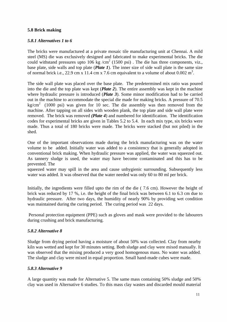
5.8 Brick making 5.8.1 Alternatives 1 to 6 The bricks were manufactured at a private mosaic tile manufacturing unit at Chennai. A mild steel (MS) die was exclusively designed and fabricated to make experimental bricks. The die could withstand pressures upto 106 kg /cm2 (1500 psi) . The die has three components, viz., base plate, side walls and top plate (Plate 1). The inner size of side wall plate is the same size of normal brick i.e., 22.9 cm x 11.4 cm x 7.6 cm equivalent to a volume of about 0.002 m3. The side wall plate was placed over the base plate. The predetermined mix ratio was poured into the die and the top plate was kept (Plate 2). The entire assembly was kept in the machine where hydraulic pressure is introduced (Plate 3). Some minor modification had to be carried out in the machine to accommodate the special die made for making bricks. A pressure of 70.5 kg/cm2 (1000 psi) was given for 10 sec. The die assembly was then removed from the machine. After tapping on all sides with wooden plank, the top plate and side wall plate were removed. The brick was removed (Plate 4) and numbered for identification. The identification codes for experimental bricks are given in Tables 5.2 to 5.4. In each mix type, six bricks were made. Thus a total of 180 bricks were made. The bricks were stacked (but not piled) in the shed. One of the important observations made during the brick manufacturing was on the water volume to be added. Initially water was added to a consistency that is generally adopted in conventional brick making. When hydraulic pressure was applied, the water was squeezed out. As tannery sludge is used, the water may have become contaminated and this has to be prevented. The squeezed water may spill in the area and cause unhygienic surrounding. Subsequently less water was added. It was observed that the water needed was only 60 to 80 ml per brick.
Initially, the ingredients were filled upto the rim of the die ( 7.6 cm). However the height of brick was reduced by 17 %, i.e. the height of the final brick was between 6.1 to 6.3 cm due to hydraulic pressure. After two days, the humidity of nearly 90% by providing wet condition was maintained during the curing period. The curing period was 22 days. Personal protection equipment (PPE) such as gloves and mask were provided to the labourers during crushing and brick manufacturing. 5.8.2 Alternative 8 Sludge from drying period having a moisture of about 50% was collected. Clay from nearby kiln was wetted and kept for 30 minutes setting. Both sludge and clay were mixed manually. It was observed that the mixing produced a very good homogenous mass. No water was added. The sludge and clay were mixed in equal proportion. Small hand-made cubes were made. 5.8.3 Alternative 9 A large quantity was made for Alternative 5. The same mass containing 50% sludge and 50% clay was used in Alternative 6 studies. To this mass clay wastes and discarded mould material

12
(Gypsum sludge) were added in equal proportion. Hand-made cubes were made. It was observed that the moisture present in sludge-clay mixture was absorbed by the ceramic wastes and hardened within a few minutes.
Table 5.2: Identification Of Bricks - Ranitec CETP (Sludge : Admixture)
Blank
30 :70 40:60 50:50 60:40 70:30 Alternative I. Coarse sludge + Clay Soil RC 11 12 13 14 15 Alternative 2 Coarse Sludge + fly ash + lime +
RF 16 17 18 19 20 Alternative 3 Pulverized Sludge + Clay Soil PS 21 22 23 24 25 Alternative 4 Pulverized sludge + Fly ash + lime +
PSF 26 27 28 29 30 Alternative 5 Pulverized sludge + Brick clay PSC 31 32 33 34 35 Alternative 6 Pulverized Sludge + Brick Clay +
PSBCF 36 37 38 39 40 Alternative 7 Pulverized Sludge + Cement CC 41 Alternative 8 Wet Sludge + Brick clay + sand -- -- -- 42 -- -- Alternative 9 Wet Sludge + Wastes from ceramic -- -- -- 43, 44 -- -- * Blank are those where no sludge has been added, letters are identification codes.
Table 5.3: Identification Of Bricks - CETP-SIDCO, Ranipet (Sludge : Admixture)
Blank
30 :70 40:60 50:50 60:40 70:30 Alternative I. Coarse sludge + Clay Soil RC 51 52 53 54 55 Alternative 2 Coarse Sludge + Fly Ash + lime +
RF 56 57 58 59 60 Alternative 3 Pulverized Sludge + Clay Soil PS 61 62 63 64 65 Alternative 4 Pulverized sludge + Fly ash + lime +
PSF 66 67 68 69 70 Alternative 5 Pulverized sludge + Brick clay PSC 71 72 73 74 75 Alternative 6 Pulverized Sludge + Brick Clay +
PSBCF 76 77 78 79 80 Alternative 7 Pulverized Sludge + Cement CC 81 82 83 Alternative 8 Wet Sludge + Brick clay + sand -- -- -- -- -- -- Alternative 9 Wet Sludge + Wastes from ceramic -- -- -- --- -- -- * Blank are those where no sludge has been added, letters are identification codes.
Table 5.4: Identification of bricks – CETP- Vishtec, Melvisharam (Sludge :Admixture)
Blank
30
40:60 50:50 60:40 70:30 Alternative I. Coarse sludge + Clay Soil RC 91 92 93 94 95 Alternative 2 Coarse Sludge + Fly Ash + lime +
RF 96 97 98 99 100 Alternative 3 Pulverized Sludge + Clay Soil PS 101 102 103 104 105 Alternative 4 Pulverized sludge + Fly ash + lime
PSF 106 107 108 109 110 Alternative 5 Pulverized sludge + Brick clay PSC 111 112 113 114 115 Alternative 6 Pulverized Sludge + Brick Clay +
PSBCF 116 117 118 119 120 Alternative 7 Pulverized Sludge + Cement CC 121 122 123 Alternative 8 Wet Sludge + Brick clay + sand -- -- -- -- -- -- Alternative 9 Wet Sludge + Wastes from ceramic -- -- -- --- -- -- * Blank are those where no sludge has been added, letters are identification codes.
6. RESULTS AND INTERPRETATION 6.1 Introduction The main objective of S/S is to make the waste immobilized and non-leachable. The accepted practice of testing the efficacy of S/S is through leachate generating potential. Immersion test was adopted till few years back. But recently, US EPA has recommended to carry out TCLP or EP Toxicity tests. However, in this study, both tests have been carried out to assess the leaching potential of bricks especially with respect to heavy metals. Among the various heavy metals,
13
chromium has been considered as tracer. However nickel was monitored as an additional parameter. The details of TCLP and Immersion tests are given in Annexes 3 and 4. 6.2 Physical Observation of Bricks The inner size of die used for making bricks is 22.9 cm (length) x 11.8 cm (width) x 7.6 cm (height). Initially mix was added to rim level i.e., upto 7.6 cm. However after applying hydraulic pressure, the height was reduced in all bricks due to compression. The height was reduced to 6.3 cm - 6.5 cm, reduction of about 14.5 to 17 %. The colour of the bricks was mostly grey. The average density of the bricks was 1.4 g/cm3. The dry weight of bricks varied from 2.13 kg to 2.218 kg (after curing). Due to moderate particle size of sludge and clay, honeycomb was observed for the bricks made with crushed sludge (Alt.1 ). This was observed even in the bricks treated with fly ash (Alt 2). There is no significant difference between clay treated bricks and fly ash treated bricks. The honey comb structure is not desirable in bricks as this would reduce the strength. In order to overcome this, the dried sludge was pulverized and sieved and this was used for the subsequent studies (Alternatives 3 to 7). 6.3 Ranitec CETP, Ranipet 6.3.1 TCLP Method Care was taken in all steps to obtain representative samples. However there could be some deviation while making bricks. In order to overcome this, two bricks from each mix were taken and grounded to fine powder. The powder was mixed thoroughly. This step was a sort of Quality Assurance (QA) programme. 5 grams of sample was weighed accurately and transferred into a conical flask. After checking pH and after taking all steps as detailed in Annex 3, extraction fluid No. 2 was added. The flasks were kept in a shaker for 24 hours in the absence of ZHE Extractor. The extracted sample was analyzed for pH, chromium and nickel in all samples. The data is presented in Table 6.1. All samples exhibited acidic pH, the condition in which TCLP tests are carried out. pH was checked during extraction and was maintained less than 5 through addition of extraction fluid No. 2. The samples were analyzed only for chromium. However nickel, the second predominant heavy metal in tannery sludge, was also monitored as an additional input parameter and for counter check. Both heavy metals were not traced in any samples in all alternatives even at 70% proportion of sludge. Soils in and around the Ranitec CETP has a low clay content (29 %). Due to higher content of silt, the soil may behave differently from the other CETPs in the Ranipet area, specifically the CETP-SIDCO. 6.3.2 Immersion Test In early periods before advent of TCLP method, leaching potential was originally tested through immersion test (Annex 4). In general, the S/S blocks would be immersed in water upto 90 days. Water samples are drawn periodically to test the leaching potential see Table 6.2. In view of long exposure period in this matter, TCLP tests are recommended. Since the local soils are used for making unburnt bricks, it was decided to conduct immersion test also to study the behavior

14
as an additional check. In addition, bricks without addition of sludge were also made to act as control.
Table 6.1: Analysis of Bricks Samples - Ranitec CETP - TCLP Method
# pH Nickel Chromiu
Sl.No pH Nickel Chromium ALT 1 ALT 4 11 4.9 BDL BDL 26 5.1 BDL BDL 12 4.9 BDL BDL 27 5.3 BDL BDL 13 4.5 BDL BDL 28 4.6 BDL BDL 14 4.2 BDL BDL 29 4.4 BDL BDL 15 4.6 BDL BDL 30 4.3 BDL BDL ALT 2
ALT 5
17 4.3 BDL BDL 32 4.2 BDL BDL 18 4.6 BDL BDL 33 4.3 BDL BDL 19 4.2 BDL BDL 34 4.2 BDL BDL 20 4.3 BDL BDL 35 4.5 BDL BDL ALT 3
ALT 6
22 4.8 BDL BDL 37 4.2 BDL BDL 23 4.2 BDL BDL 38 4.5 BDL BDL 24 4.3 BDL BDL 39 4.8 BDL BDL 25 4 2 BDL BDL 40 4 5 BDL BDL
Note: All values in mg/l BDL : Below Detectable Level
Please refer Table 5.2 for decoding sample numbers
Table 6.2: Analysis of brick samples - Ranitec CETP, Ranipet - Immersion test (chromium, mg/l)
_______________________________________________________________ EXPOSURE PERIOD (Days) ----------------------------------------------------------------------------------------------- Sample No 1 2 3 4 5 10 20 30 No ______________________________________________________________________ ALT 1 11 BDL BDL BDL BDL BDL BDL BDL BDL 12 BDL BDL BDL BDL BDL BDL BDL BDL 13 BDL BDL BDL BDL BDL BDL BDL BDL 14 BDL BDL BDL BDL BDL BDL BDL BDL 15 BDL BDL BDL BDL BDL BDL BDL BDL ALT 2 16 BDL BDL BDL BDL BDL BDL BDL BDL 17 BDL BDL BDL BDL BDL BDL BDL BDL 18 BDL BDL BDL BDL BDL BDL BDL BDL 19 BDL BDL BDL BDL BDL BDL BDL BDL 20 BDL BDL BDL BDL BDL BDL BDL BDL ALT 3 21 BDL BDL BDL BDL BDL -- --- --- 22 BDL BDL BDL BDL BDL -- -- -- 23 BDL BDL BDL BDL BDL -- -- -- 24 BDL BDL BDL BDL BDL -- -- -- 25 BDL BDL BDL BDL BDL -- -- ---

15
The bricks were immersed in plastic buckets (5 liter capacity) and tap water was used. No chromium was present in the tap water. The bricks did not disintegrate during the first two days. However all bricks including control bricks did show disintegration from third day. All bricks got dissolved by fifth day. This was perhaps due to : Too low percentage of clay and higher sand content in the local soils near CETPs under study.
• The average particle size of sludge and soil was around 5 to 6 mm. The coarse size in the presence of sand could not achieve cohesiveness which is essential in consolidation process.
• Although a hydraulic pressure of around 70.5 kg/m2 (1000 psi) was applied, the coarse particle did not get pulverized leaving honey combs formation (Alternative 1).
Chromium was not detected in any sample. This indicates that the chromium was not leaching. However, the bricks made from brick-clay did not disintegrate even after 30 days. When cement was added, the bricks did not disintegrate and was hardened. When wastes from a ceramic industry was added, the bricks did not disintegrate even after 20 days. In order to study the behavior of leaching with water, the bricks were powdered and water was added adopting multiple extraction method (Annex 5). The leachate was tested both for hexavalent and trivalent chromium. The data are presented in Table 6.3. The chromium both in the form of hexavalent and trivalent forms were absent in all samples.
Table 6.3: Analysis of brick samples - Multiple extraction procedure (MEP) Chromium (mg/l)
Extraction Stage
# I II III, IV & V 13* BDL BDL BDL 20 BDL BDL BDL 21* BDL BDL BDL 29 BDL BDL BDL 33 BDL BDL BDL
6.4 CETP-SIDCO, Ranipet 6.4.1 TCLP Method
Table 6.4: Analysis of bricks samples - CETP-SIDCO - TCLP Method # pH Nickel Chromium
# pH Nickel Chromium
ALT 1 51
4.0
BDL
1.2
ALT 4 66
4.6
BDL
BDL
52 4.3 BDL 1.8 67 4.3 BDL BDL 53 4.5 0.2 2.4 68 4.6 BDL BDL

16
54 4.5 BDL 2.4 69 4.2 BDL BDL 55 5.1 BDL 2.4 70 4.3 BDL BDL ALT 2 56
4.9
BDL
1.8
ALT 5 71
4.9
BDL
BDL
57 5.0 BDL 1.8 72 4.8 BDL BDL 58 5.2 BDL 2.4 73 4.2 BDL BDL 59 5.2 BDL 2.4 74 4.3 BDL BDL 60 5.2 BDL 2.4 75 4.5 BDL BDL ALT 3 61
4.9
BDL
BDL
ALT 6 76
5.1
BDL
BDL
62 4.9 BDL BDL 77 5.3 BDL BDL 63 4.5 BDL BDL 78 4.6 BDL BDL 64 4.2 BDL BDL 79 4.4 BDL BDL 65 4.6 BDL BDL 80 4.3 BDL BDL pH Nickel Chromium ALT 7 81 4.7 BDL BDL 82 4.8 BDL 0.2 83 4.3 BDL 0.3
Note: All values in mg/l BDL : Below Detectable Level
Please refer Table 5.3 for decoding sample numbers
The data on the leaching potential by TCLP method on the bricks made from SIDCO sludge for various admixtures are presented in Table 6.4. The pH in all samples were below 5.2 indicating effective extraction. The chromium was present in the leachate in the bricks made from coarse sludge under Alternatives 1 and 2. The chromium content in the leachate varied from 1.2 mg/l to 2.4 mg/l. The lowest concentration of 1.2 mg/l was recorded in the bricks where Sludge was mixed with the local clayey soil in the ratio of 30:70. When the ratio of sludge to admixture was more than 50:50, the chromium concentration was nearly doubled. The maximum chromium concentration in the leachate was 2.4 mg/l. Assuming the dilution factor of 100, the probable chromium concentration in the ground water would be 100 times less i.e. the chromium concentration would be about 0.024 mg/l which is far below the permissible limit of 0.5 mg/l. Thus it can be concluded that the leachate from bricks made with higher concentration of chromium would not pollute the ground water. Both heavy metals were not traced in any samples in all other alternatives (Alternatives 3 to 7) even at 70% proportion of sludge.
6.4.2 Immersion Test
In this case also, like Ranitec, the bricks made from coarse sludge got disintegrated within 10 days. The chromium leaching was observed in the water samples where coarse sludge with local soil was used for making bricks (Alternative 1). It was observed that the chromium leaching was highest on the first day and showed downward trend with the increasing exposure period. Chromium was not recorded after 3 days when the sludge : admixture was less than 50:50. However with increased sludge proportion, the chromium was not recorded after 5 days. The cumulative chromium concentration was 4.5 mg/l. Assuming the dilution factor of 100, the chromium concentration in the ground water would be about 0.045 mg/l which is nearing the permissible limit of 0.5 mg/l. Thus it can be concluded that the sludge : admixture ratio should

17
not be more than 50:50 to prevent ground water contamination. However when fly ash was added to the coarse sludge (Alternative 2), no chromium leaching was observed even at high sludge : admixture ratios. The chromium leaching was retarded by the addition of fly ash and lime.
Table 6.5: Analysis of Brick Samples - CETP-SIDCO, Ranipet - Immersion Test Chromium (mg/l)
_______________________________________________ Exposure Period (days) ------------------------------------------------------------ Sample No. 1 2 3 4 5 10 ________________________________________________ ALT 1 51 1.0 0.4 0.2 BDL BDL BDL 52 1.4 0.5 0.3 0.2 BDL BDL 53 1.4 0.4 0.2 BDL BDL BDL 54 1.8 1.6 1.0 0.8 0.3 BDL 55 2.1 1.4 0.7 0.3 BDL BDL ALT 2 56 BDL BDL BDL BDL BDL BDL 57 BDL BDL BDL BDL BDL BDL 58 BDL BDL BDL BDL BDL BDL 59 BDL BDL BDL BDL BDL BDL 60 BDL BDL BDL BDL BDL BDL ALT 3 61 BDL BDL BDL BDL BDL BDL 62 BDL BDL BDL BDL BDL BDL 63 BDL BDL BDL BDL BDL BDL 64 BDL BDL BDL BDL BDL BDL 65 BDL BDL BDL BDL BDL BDL ALT 4 66 BDL BDL BDL BDL BDL BDL 67 BDL BDL BDL BDL BDL BDL 68 BDL BDL BDL BDL BDL BDL 69 BDL BDL BDL BDL BDL BDL 70 BDL BDL BDL BDL BDL BDL ALT 5 71 BDL BDL BDL BDL BDL BDL 72 BDL BDL BDL BDL BDL BDL 73 BDL BDL BDL BDL BDL BDL 74 BDL BDL BDL BDL BDL BDL 75 BDL BDL BDL BDL BDL BDL ALT 6 76 BDL BDL BDL BDL BDL BDL 77 BDL BDL BDL BDL BDL BDL 78 BDL BDL BDL BDL BDL BDL 79 BDL BDL BDL BDL BDL BDL 80 BDL BDL BDL BDL BDL BDL
18
ALT 7
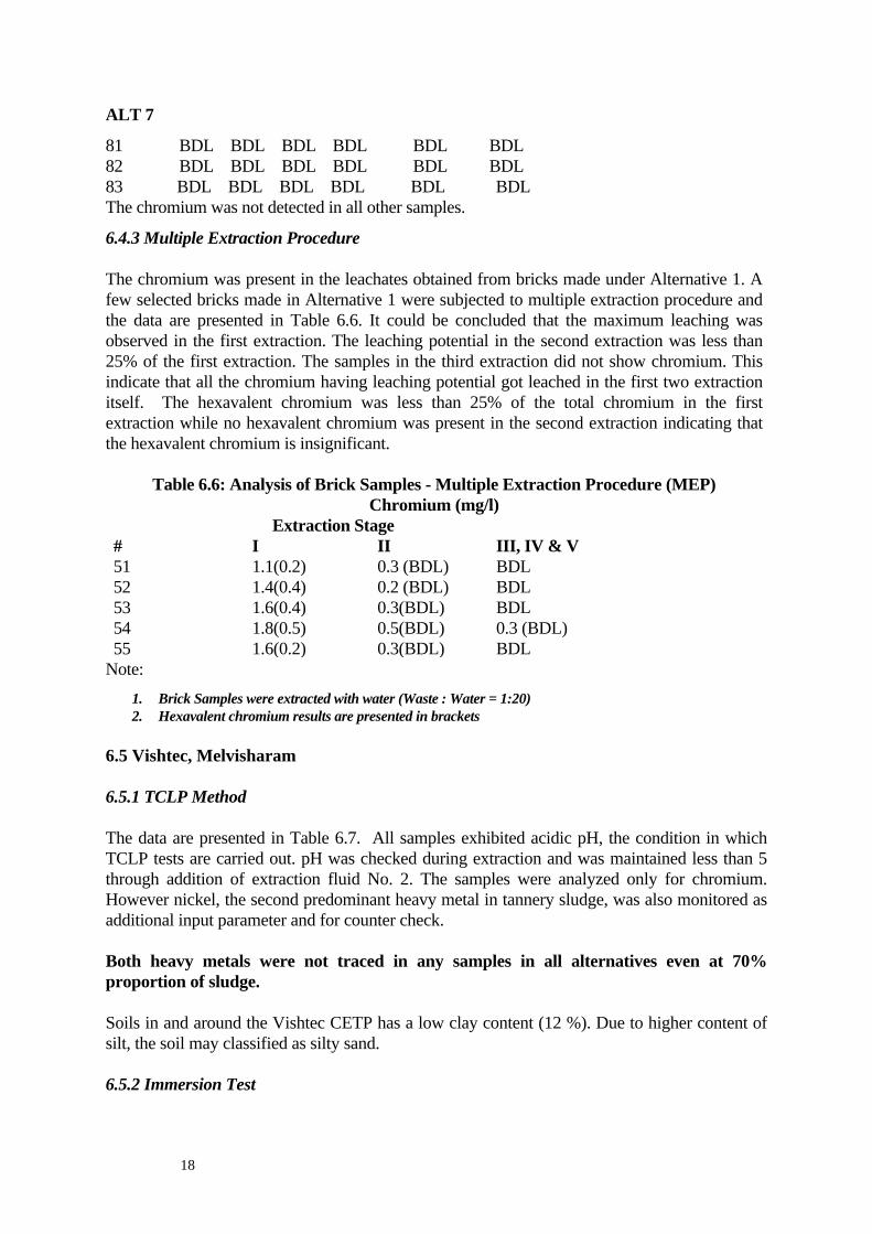
81 BDL BDL BDL BDL BDL BDL 82 BDL BDL BDL BDL BDL BDL 83 BDL BDL BDL BDL BDL BDL The chromium was not detected in all other samples.
6.4.3 Multiple Extraction Procedure The chromium was present in the leachates obtained from bricks made under Alternative 1. A few selected bricks made in Alternative 1 were subjected to multiple extraction procedure and the data are presented in Table 6.6. It could be concluded that the maximum leaching was observed in the first extraction. The leaching potential in the second extraction was less than 25% of the first extraction. The samples in the third extraction did not show chromium. This indicate that all the chromium having leaching potential got leached in the first two extraction itself. The hexavalent chromium was less than 25% of the total chromium in the first extraction while no hexavalent chromium was present in the second extraction indicating that the hexavalent chromium is insignificant.
Table 6.6: Analysis of Brick Samples - Multiple Extraction Procedure (MEP) Chromium (mg/l)
Extraction Stage # I II III, IV & V 51 1.1(0.2) 0.3 (BDL) BDL 52 1.4(0.4) 0.2 (BDL) BDL 53 1.6(0.4) 0.3(BDL) BDL 54 1.8(0.5) 0.5(BDL) 0.3 (BDL) 55 1.6(0.2) 0.3(BDL) BDL
Note: 1. Brick Samples were extracted with water (Waste : Water = 1:20) 2. Hexavalent chromium results are presented in brackets
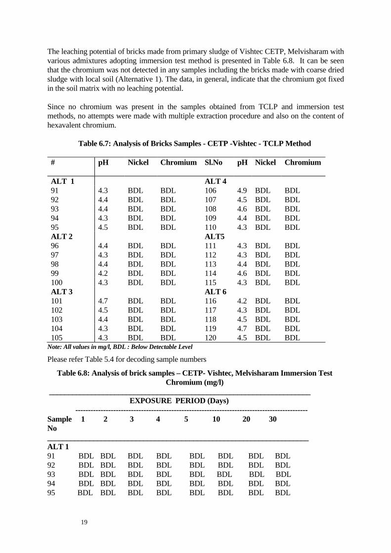
6.5 Vishtec, Melvisharam 6.5.1 TCLP Method The data are presented in Table 6.7. All samples exhibited acidic pH, the condition in which TCLP tests are carried out. pH was checked during extraction and was maintained less than 5 through addition of extraction fluid No. 2. The samples were analyzed only for chromium. However nickel, the second predominant heavy metal in tannery sludge, was also monitored as additional input parameter and for counter check. Both heavy metals were not traced in any samples in all alternatives even at 70% proportion of sludge. Soils in and around the Vishtec CETP has a low clay content (12 %). Due to higher content of silt, the soil may classified as silty sand. 6.5.2 Immersion Test
19
The leaching potential of bricks made from primary sludge of Vishtec CETP, Melvisharam with various admixtures adopting immersion test method is presented in Table 6.8. It can be seen that the chromium was not detected in any samples including the bricks made with coarse dried sludge with local soil (Alternative 1). The data, in general, indicate that the chromium got fixed in the soil matrix with no leaching potential. Since no chromium was present in the samples obtained from TCLP and immersion test methods, no attempts were made with multiple extraction procedure and also on the content of hexavalent chromium.
Table 6.7: Analysis of Bricks Samples - CETP -Vishtec - TCLP Method #
pH Nickel Chromium
Sl.No pH Nickel Chromium
ALT 1 ALT 4 91 4.3 BDL BDL 106 4.9 BDL BDL 92 4.4 BDL BDL 107 4.5 BDL BDL 93 4.4 BDL BDL 108 4.6 BDL BDL 94 4.3 BDL BDL 109 4.4 BDL BDL 95 4.5 BDL BDL 110 4.3 BDL BDL ALT 2 96
4.4
BDL
BDL
ALT5 111
4.3
BDL
BDL
97 4.3 BDL BDL 112 4.3 BDL BDL 98 4.4 BDL BDL 113 4.4 BDL BDL 99 4.2 BDL BDL 114 4.6 BDL BDL 100 4.3 BDL BDL 115 4.3 BDL BDL ALT 3 101
4.7
BDL
BDL
ALT 6 116
4.2
BDL
BDL
102 4.5 BDL BDL 117 4.3 BDL BDL 103 4.4 BDL BDL 118 4.5 BDL BDL 104 4.3 BDL BDL 119 4.7 BDL BDL 105 4.3 BDL BDL 120 4.5 BDL BDL
Note: All values in mg/l, BDL : Below Detectable Level
Please refer Table 5.4 for decoding sample numbers
Table 6.8: Analysis of brick samples – CETP- Vishtec, Melvisharam Immersion Test Chromium (mg/l)
____________________________________________________________________ EXPOSURE PERIOD (Days) -------------------------------------------------------------------------------------------- Sample 1 2 3 4 5 10 20 30 No ____________________________________________________________________ ALT 1 91 BDL BDL BDL BDL BDL BDL BDL BDL 92 BDL BDL BDL BDL BDL BDL BDL BDL 93 BDL BDL BDL BDL BDL BDL BDL BDL 94 BDL BDL BDL BDL BDL BDL BDL BDL 95 BDL BDL BDL BDL BDL BDL BDL BDL

20
ALT 2 96 BDL BDL BDL BDL BDL BDL BDL BDL 97 BDL BDL BDL BDL BDL BDL BDL BDL 98 BDL BDL BDL BDL BDL BDL BDL BDL 99 BDL BDL BDL BDL BDL BDL BDL BDL 100 BDL BDL BDL BDL BDL BDL BDL BDL ALT 3 101 BDL BDL BDL BDL BDL BDL BDL BDL 102 BDL BDL BDL BDL BDL -- -- -- 103 BDL BDL BDL BDL BDL -- -- -- 104 BDL BDL BDL BDL BDL -- -- -- 105 BDL BDL BDL BDL BDL BDL BDL BDL 7. PRELIMINARY COST ANALYSIS 7.1 Introduction The primary chemical sludge generated from tannery CETPs has to be disposed in an environmentally compatible manner to minimise the adverse impact on soil and water environments. This can be achieved through disposing the sludge in secure landfill. The land disposal requires suitable land and proper liner materials. The vast land area requirement and other stringent specifications of landfill may make the landfill costlier. It is therefore felt necessary to develop suitable treatment and disposal alternative with the aim of utilising the sludge. After reviewing various alternatives, it was decided to study the feasibility of making chemically immobolised material. Hence studies were conducted on solidification / stabilisation. As seen from Chapter 6 S/S is possible for tannery sludges. In order to evaluate the economics of the technology, attempts are made to estimate the cost of S/S and compare this with the cost of landfill. For illustration, the sludge generated from Ranitec, Ranipet is considered. 7.2 Secure Landfill The sludge generation from the primary treatment at Ranitec is around 20 Tons per day which is equivalent to 15 m3/d .The average design period of secure landfill is 20 years. The total volume of sludge to be disposed is 109,500 m3 for the entire period. The land area required works out to be 7 ha for the effective waste layer depth of 6 m. The basic data assumed for the design of secure landfill is presented in Table 7.1. The cost for various elements of landfill is shown in Table 7.2. The total cost is computed as Rs 33.8 millions which is equivalent to Rs 309 /m3. The operation cost per year is about Rs 2.04 million. In addition to higher capital and operation costs, there may be the risk of ground water contamination if improper design assumptions, use of unsuitable materials in the construction and inefficient operation occur. Further stringent monitoring of the ground water in the vicinity of landfill would be an additional responsibility on the proponent. 7.3 Solidification / Stabilisation As an alternative to land disposal, the present studies reveal that S/S is a suitable technology. The main advantage of this method is to achieve chemically immobolised mass which will
21
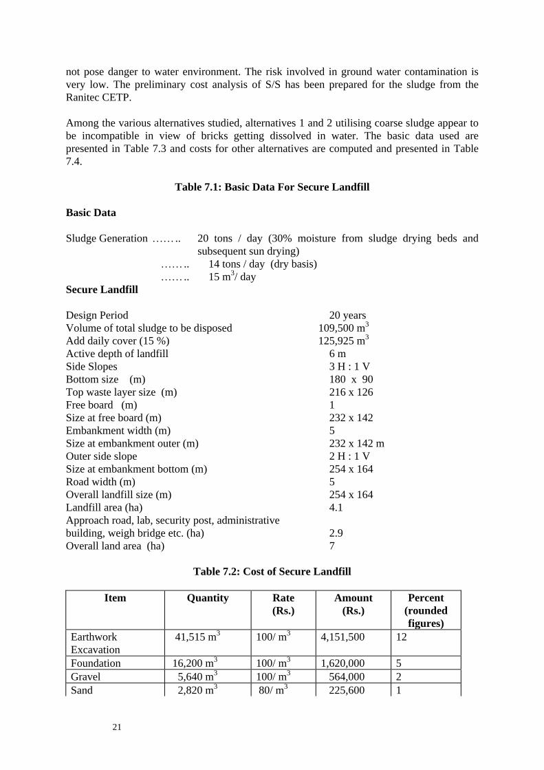
not pose danger to water environment. The risk involved in ground water contamination is very low. The preliminary cost analysis of S/S has been prepared for the sludge from the Ranitec CETP. Among the various alternatives studied, alternatives 1 and 2 utilising coarse sludge appear to be incompatible in view of bricks getting dissolved in water. The basic data used are presented in Table 7.3 and costs for other alternatives are computed and presented in Table 7.4.
Table 7.1: Basic Data For Secure Landfill Basic Data Sludge Generation …….. 20 tons / day (30% moisture from sludge drying beds and
subsequent sun drying) …….. 14 tons / day (dry basis) …….. 15 m3/ day Secure Landfill Design Period 20 years Volume of total sludge to be disposed 109,500 m3 Add daily cover (15 %) 125,925 m3 Active depth of landfill 6 m Side Slopes 3 H : 1 V Bottom size (m) 180 x 90 Top waste layer size (m) 216 x 126 Free board (m) 1 Size at free board (m) 232 x 142 Embankment width (m) 5 Size at embankment outer (m) 232 x 142 m Outer side slope 2 H : 1 V Size at embankment bottom (m) 254 x 164 Road width (m) 5 Overall landfill size (m) 254 x 164 Landfill area (ha) 4.1 Approach road, lab, security post, administrative building, weigh bridge etc. (ha) 2.9 Overall land area (ha) 7
Table 7.2: Cost of Secure Landfill
Item Quantity Rate (Rs.)
Amount (Rs.)
Percent (rounded figures)
Earthwork Excavation
41,515 m3 100/ m3 4,151,500 12
Foundation 16,200 m3 100/ m3 1,620,000 5 Gravel 5,640 m3 100/ m3 564,000 2 Sand 2,820 m3 80/ m3 225,600 1

22
Cover Clay 2,430 m3 100/ m3 243,000 1 HDPE(1mm) 23,000 m2 250/ m2 5,750,000 17 Geonet 23,000 m2 100/ m2 2,300,000 7 Embankment 181,532 m3 100/ m3 18,153,200 54 Anchor block 240 m3 1500/ m3 360,000 1 PVC pipe (main) 180 m 75/m 13,500 0 PVC pipe (Lateral) 1584 m 25/m 39,600 0 Sump LS LS 40,000 0 Piezometer 16 25000/each 400,000 1 Total -- -- 33,860,400 100
Note : Cost of land, cost of site preparation, approach roads, green belt, documentation, detailed engineering, etc. are not included: To the above, add about 15% as contingency Operation Cost (per year) Waste Placement - Transportation Cost Rs 1,200,000 - Unskilled labours (5/d) Rs 360,000 Intermediate cover Rs 50,000 Ground water monitoring Rs 50,000 Leachate monitoring Rs 20,000 Land surface care Rs 10,000 Leachate pipeline cleaning Rs 10,000 Annual assessment Rs 20,000 Administration & Contingency Rs 300,000 Replacement of equipment Rs 20,000 Total Rs 2,040,000 Note : The O&M cost does not include annualised capital cost. Capital cost per m3 Rs. 309 Operating cost per m3 (calculated on yearly basis) Rs. 376
Table 7.3: Basic data used for costing s/s Size of brick (cm) 23 x 11.5 x 5.75 Volume of brick (cm3) 1521 (or) 0.0015 m3 Volume of S/S mass after compacting 0.0015 m3 Volume of S/S mass before compacting 0.0225 m3 Sludge : clay ratio 60 : 40 Sludge needed per brick 0.00135 m3 Clay needed per brick 0.00081 m3 Sand needed per brick 0.00009 m3 Sludge generation per day 14 tons /day (dry basis) or 15 m3/day No. of bricks that can be made/day 11,111 Say 11,000 Raw material required for 11000 bricks/d :

23
Sludge 14.85 m3 Clay 8.91 m3 Sand 0.99 m3 Water : - Process 2.20 m3 - Other uses 4.40 m3 Land Requirement for S/S (m2) Space for mixing 100 Brick making 200 Drying ( 5 days) 2200 Misc. 700 Total area 3200 say 4000 (Brick kiln if required an additional space of about 5000 m2 may be added) Brick storage yard 2500 m2
Table 7.4: Capital Cost For S/S (Indian rupees in 100,000) Units Alt 3* Alt 4* Alt 5* Alt 6* Alt 7* Alt 8* Drier 7.0 7.0 7.0 7.0 7.0 -- Pulveriser 8.0 8.0 8.0 8.0 8.0 -- Mixer 8.0 8.0 8.0 8.0 8.0 8.0 Mechanical brick making 10.0 10.0 10.0 10.0 10.0 10.0 Accessories 5.0 5.0 5.0 5.0 5.0 5.0 Flyash & lime -- 0.05 -- 0.10 -- -- Cement -- -- -- -- 0.03 -- Brick clay -- -- 0.05 0.05 0.05 0.05 Total 38.0 38.05 38.05 38.15 38.08 23.05
* For reference on alternatives refer to Page 30 bottom part Operational Cost (Indian Rupees (hunderds) /day) Unit Alt 3 Alt 4 Alt 5 Alt 6 Alt 7 Alt 8 Electrical energy 11.00 11.00 11.00 11.00 11.00 4.00 Labour 10.00 10.00 10.00 10.00 10.00 8.00 Clay & Sand 5.40 5.40 5.40 5.40 5.40 5.40 Flyash & lime -- 25.20 -- 25.20 -- -- Cement -- -- -- -- 6.48 -- Water 4.0 4.0 4.0 4.0 4.0 2.0 Total 30.40 51.60 30.40 55.60 36.88 19.0

24
Note : The O&M cost does not include contingenciesNote : The O&M cost does not include contingenciesNote : The O&M cost does not include contingenciesNote : The O&M cost does not include contingenciesNote : The O&M cost does not include contingencies
Alt 3 Alt 4 Alt 5 Alt 6 Alt 7 Alt 8 Cost/brick 0.80 1.35 0.8 1.46 0.97 0.50

25
Legend :
Alternative 3 Pulverized Sludge + Clay Soil
Alternative 4 Pulverized sludge + Fly ash + lime + sand
Alternative 5 Pulverized sludge + Brick clay
Alternative 6 Pulverized Sludge + Brick Clay + Flyash
Alternative 7 Pulverized Sludge + Cement
Alternative 8 Wet Sludge + Brick clay + sand
Alternative 9 Wet Sludge + Wastes from ceramic
8. CONCLUSION The sludge generated from tannery CETPs, like any other industry sectors, is currently stored within the CETP premises without any precautionary measures. This is perhaps due to the fact that suitable disposal site(s) have not been made available to the industries by the state regulatory authorities. As per the HWM Rules, 1989 in India, the state regulatory agency has to select and notify the disposal sites. Since the hazardous waste management is in infant stage and since no secure landfill design criteria are available for tropical countries, pilot demonstration secure landfills have been constructed by UNIDO at Ranitec, Ranipet and is under consideration for Vishtec, Melvisharam. The current project is aimed at assessing the efficacy of S/S technology for sludges from CETPs for tannery effluent. This has been considered due to its many advantages. The S/S technology may be acceptable to tanners if the native soil is used as admixture and hence it is cost effective. Considering the likely technical and economic advantages of S/S, the studies were carried out for the sludge collected from three CETPs located in Ranipet area in the state of Tamilnadu. In this study, various admixtures were mixed with primary chemical sludge collected from three CETPs to study the leaching potential of chromium, the main pollutant present in the waste sludge. Initially, native soils present in and around the CETPs have been considered to obtain chemically immobilized and non-leachable unburnt bricks. In addition, fly ash from thermal power plant has been tried for its compatibility with tannery sludge. Burning of bricks has not been done for the reason that uncontrolled burning may lead to Cr III being converted into Cr IV. Sludge from three CETPs was collected for 10 days and mixed to obtain a representative sample. The dried samples were crushed (not pulverized/powdered) and local clayey soil as admixtures were mixed in various proportions ranging from 30:70 to 70:30 (sludge : admixture). The unburnt bricks were made using a die designed and fabricated exclusively for this PDU. After 22 days curing, the samples were tested for assessing the leaching potential. Due to coarse state of sludge, the bricks exhibited honeycomb structure leading to very low strength. In the second phase of the studies, dried sludges were pulverized to obtain a fine powder. The bricks did not exhibit chromium leaching even at high sludge : admixture ratio (70:30). The
26
honeycomb structure was absent. It is interesting to observe that the sludge from Ranitec could not be pulverized to fine powder. The sludge after drying gets elongated and behaved as polymerised substance. The bricks with lower sludge : admixture ratio (<50:50) did not immediately get disintegrated, however the bricks started disintegrating after 10 days immersion in water. Despite the low clay content and high sand content in local soils near all three CETPs, the S/S studies indicated that the chromium and other heavy metals got fixed in the soil matrix and did not exhibit leaching potential. The leaching of chromium was absent. It is therefore necessary to improve the structural stability in addition to chemical stability to make the S/S more attractive and acceptable. The reason for disintegration could be due to high percentage of sand with a very low clay content in the admixture and medium particle size of sludge and soil (4 to 6 mm). It is believed that better strength and cohesive bricks could be obtained provided the sludge and soil are pulverized and application of clayey soil having clay content more than 45% with corresponding lower sand content. Thus the clay from nearby brick kiln was used as admixture. It was observed that the bricks did not disintegrate. The strength slightly improved over the bricks made from the local soil. Exploratory studies revealed that the strength could be increased to 135 ksc when cement (5%v/v) was added. The acceptability of unburnt bricks by the end users appears to be remote due to physical appearance. The physical appearance and strength could be improved if the bricks are burnt. Further the bricks could be cheaper if the production is more than 7500 every day. Otherwise the bricks may be as costly as normal conventional bricks. At the same, it is necessary to assess the demand. In view of uncertainties in brick making, the solidified sludge can be used as sub grade materials over the foundation. At present murram type of soil is used. The only criteria is that the plasticity index of the solidified sludge should not be less than 6. (The plasticity index is the difference between the liquid limit and plastic limit). There is a possibility of complete utilisation of sludge generated from all CETPs subject to the acceptability by the highways department and environment authorities. As outlined in Chapter 7, the cost of making bricks could be kept minimum provided wet sludge (moisture content is around 40 to 50%) and wet clay are blended. This avoids drier, pulveriser and other unit operations. After reviewing the various alternatives, the order of preference is as follows :
Alternative 8 Wet Sludge + Brick clay + sand Alternative 7 Pulverized Sludge + Cement Alternative 6 Pulverized Sludge + Brick Clay +
Alternative 5 Pulverized sludge + Brick clay Alternative 3 Pulverized Sludge + Clay Soil Alternative 4 Pulverized sludge + Fly ash + lime Alternative 9 Wet Sludge + Wastes from ceramic

27
(Alternatives 1 & 2 are not recommended). Due to constraints in brick making, the other alternative is to make mosaic floor tiles. In this chips and white cement are mixed and made slurry by adding excess water. The slurry is poured into the die. After filling half the die, the remaining is filled with rock powder fines and cement. It was to be explored to substitute the cement with tannery sludge. The sludge has to be dried and powdered for use in mosaic tile manufacture. The cost of tile cannot be reduced. Thus no attempts were made to make mosaic tiles. This was based on the discussions with a few mosaic floor tile manufacturers in Chennai. At this stage, therefore, the bricks can be used for non-load bearing construction work and/or road foundation, since the chemical properties are quite satisfactory. As seen in Chapter 7, the capital cost of secure landfill for Ranitec to dispose about 15 m3/d for 20 years period was around 33.8 million Indian Rupees. The capital cost for S/S is around 1.9 million Indian Rupees, i.e. about 5.6 % of the capital cost for landfill. The annual operating cost for landfill is expected to be 2 million Indian Rupees. The operation cost for S/S, under the assumption that no bricks can be sold is Indian Rupees (Rs.) 1900 per day (say Rs. 2000 x 365) or 0.73 million Indian Rupees per year. In this case bricks may be used for filling material for low lying areas. Furthermore, it there is any failure in the landfill operation, groundwater contamination can not be ruled out. Hence constant vigilance is necessary. In S/S however, due to the immobility of heavy metals especially chromium, the groundwater contamination does not occur. It may be possible that bricks can be sold, in which case part of the operational cost can be recovered. The possible end uses of the bricks have been listed below : 1. Garden bricks 2. Sub base material for district roads, approach roads to CETPs, roads inside CETPs 3. Median stone in roads 4. Curb stone in streets (demarking footpath) 5. Boundary walls surrounding CETPs 6. Cow and other animal sheds in rural areas Less preferable alternative uses are : 1. Filling up of low lying areas within the CETP 2. Imperable layer below ETP units to increase the travel time of seepage 3. Barrier under the secure landfill It can therefore be stated that solidification / stablisation of tannery sludge may be presented as an acceptable method of sludge management to both regulatory authorities and the tanners.

28
Annex 1
PROJECT PROFILE
PDU/14 : SOLIDIFICATION OF SLUDGE FROM EFFLUENT TREATMENT PLANTS (ETPs) / COMMON EFFLUENT TREATMENT PLANTS (CETPs) OF
TANNERIES BY MIXING WITH CLAY AND/OR OTHER WASTE MATERIALS LIKE FLY ASH AND LIME
A. Problem to be addressed Tannery effluent treatment has become a matter of serious concern among tanneries in India over the last few years. Several individual and common effluent treatment plants are now under operation in the state of Tamilnadu and elsewhere in India. Performance in treating the liquid effluent of in the CETPs and many effluent treatment plants has been reported to be satisfactory. An area which has not found any suitable solution till date is the safe disposal of sludge generated by CETPs/ETPs. The Government of India has enacted hazardous waste (management and handling) rules in 1989. Under these rules sludge from tannery effluent treatment plants is considered as hazardous waste (waste category 12) irrespective of levels of heavy metal concentration. This implies that sludge from the tannery effluent treatment plants has to be collected and disposed in safe landfill sites. However, in the state of Tamilnadu despite the fact that eleven CETPs for tanneries and more than one hundred ETPs are operational, no (with one exception of a small temporary sludge disposal site at the Ranitec CETP, Ranipet built under UNIDO project US/) safe disposal site for tannery sludge has been developed so far. At present, therefore in all CETPs and ETPs sludge after dewatering is being disposed in land adjacent to the effluent treatment plants without proper storage mechanism. This has led to the widespread suspicion that the leachate from the sludge may contaminate the ground water. One model temporary disposal site for tannery sludge has been constructed with UNIDO support at Ranitec CETP, Ranipet. However, the capacity of the site is limited to storage of sludge generated for one year in the same CETP. In addition, none of the other CETPs has as yet constructed a similar site, except CETP at SIDCO Industrial Estate, Ranipet, which has started evaporation work. Some research work has started on the conversion of tannery sludge : composting of sludge, and direct land application. Even if successful, none of these technologies will be able to use all the sludge generated. One of the technically feasible solutions tried as small scale is conversion of sludge into bricks, by mixing it with soil clay, using specially constructed oven. However despite its technical viability the technology has not yet been widely practise because its marketability is not established. Also the technology too is complex. The current project proposes to use a basic method of mixing of sludge and (clayey soil and/or fly-ash or lime/compressed moulding), sun drying etc.. The main area of research is to identify the best mixture of sludge and other materials for each of the three operational CETPs in Ranipet. This is especially applicable to leachate formation.

29
Perceived advantages : •.Low capital investment and low running cost •.Materials required are relatively cheap and in abundance •.Techniques for process are relatively well established •.Only partial dewatering of sludge is required because material incorporates water and can be adopted to a wide range of water contents. •.Technology will find wide application, if proven conclusively and to the satisfaction of the pollution control authorities. B. Objective, output and activities Objective To identify the feasibility of a low cost conversion of tannery sludge Output Three project reports will be prepared, one for Ranitec CETP, one for Melvisharam CETP and one for CETP-SIDCO all in Ranipet. Activities •.Collect representative sludge samples (at least 3 from each of three CETP) from sludge drying beds and at least 3 samples from subsurface soil near these CETPs. •.Analyse all samples for heavy metals organics and inorganics. Soil samples will also be analyzed for caution exchange capacity and mineralogical composition. •.To identify the optimum combination between sludge from the three CETPs and other waste material / solids etc. through lab trials and on site demonstration. The trials will be as per Annex 1. •.To compress the mixture using steel moulds in normal brick size. •.To monitor whether any leachate is coming from un-burnt bricks through immersion test (30 for mixture with clayey soil and sludge and 30 for mixture of sludge and fly-ash lime) and a set of 15 samples using mixture of sludge and clayey soil and a set of 15 samples of mixture of sludge, fly-ash lime will be taken for EP toxicity analyse (using US EPA method). •.Random samples and analysis for compressive strength. •.To prepare project reports for each CETP taking into account the entire quantity of sludge generated. The project reports for each CETP will contain drawings, equipment specification, addresses of suppliers of equipment, process parameters and cost details •.The potential uses and users for the solidified bricks should be clearly indicated for each CETP and the consultant will have established contacts with potential users of bricks.
30
•.Present the findings of all of the above in a workshop which will be organised by RePO in conjunction with the environmental authorities. C. Cost The cost of the project for UNIDO are i)Recruitment of one national expert for a period of 4 months. ii)Expenses relating to testing of samples of sludge, clay and bricks of different characteristics not exceeding US $ 5700 After the technology is proven and found satisfactorily to the pollution control authorities, its wider adoption by CETPs in India is foreseen. D. Annex (job description)

31
Annex 2
JOB DESCRIPTION US/RAS/92/120/17-62
7 November, 1997 Post Title: Consultant for a project on solidification of sludge from tannery effluent treatment plant Duration: 4 months Date required: 24 November, 97 Duty Station: Home based activity (alternate Madras and Ranipet) Purpose of Project : To assist the leather industry in the selected countries of the South East Asia region to expand without causing unnecessary damage to the environment and avoiding undue economic burden to the industrial enterprises concerned. One of the main objectives of the project is to convert solid wastes from the tanning industry into useful by products. Sizeable quantities of sludge is generated in the treatment of tannery effluent and it s disposal poses a big problem at present. Currently one pilot demonstration site for safe disposal of sludge generated by one common effluent treatment plant is operational in Ranipet (Ranitec CETP under the UNIDO project US/IND/90/244). However, the quantity of sludge generated in the Ranitec CETP is such that the disposal site will be full within one year of operation. Therefore there is an urgent need to identify possible alternatives modes of utilisation/disposal of sludge. One of the options being recommended is solidification and stabilisation of tannery sludge. In this process sludge is converted into an insoluble rock-like material by addition of clay or any locally available waste like fly ash. The solidification process results in a monolithic block with high structural integrity, whilst the stabilisation limits the solubility of the pollutant. If the lab trials are successful and conclusive, this technology may be relevant for many countries in the region. Duties: The National Consultant will be working in close collaboration with the Regional Programme Office (RePO) of the Regional Programme for Pollution Control in the Tanning Industry in South East Asia in Madras, India and report to the Programme Coordinator. He / she will also work in close collaboration with the managements of the three identified CETPs in Ranipet. He / she will specifically be expected to: 1. Collect representative sludge samples (at least 3 sets from each of the three CETPs) from
sludge drying beds and at least 3 samples from subsurface soil near CETPs. 2. Analyse all samples for heavy metals organics and inorganics. Soil samples will also be
analyzed for caution exchange capacity and mineralogical composition.

32
3. To identify the optimum combination between sludge from the three CETPs and other waste material / solids etc. through lab trials and on site demonstration. The trials will be as per Annex 1.
4. To compress the mixture in steel moulds of normal brick size and the un-burnt bricks). 5. To monitor whether any leachate is coming from bricks through immersion test (30 for
mixture with clayey soil and sludge and 30 for mixture of sludge and fly-ash lime) and a set of 15 samples using mixture of sludge and clayey soil and a set of 15 samples of mixture of sludge, fly-ash and lime will be taken for EP toxicity analyse (using US EPA method).
6. Random samples and analysis of these for compressive strength. 7. To prepare project reports for each CETP taking into account the entire quantity of sludge
generated. The project reports for each CETP will contain drawings, equipment specification, addresses of suppliers of equipment, process parameters and cost details.
8. The potential uses and users for the solidified bricks should be clearly indicated for each
CETP and the consultant will have established contacts with potential users of bricks. 9. Present the findings of all of the above in a workshop which will be organised by RePO in
conjunction with the environmental authorities. The Consultant will be expected to report on the assignment in accordance with the reporting system established in UNIDO and will be expected to prepare a technical report, setting out his recommendations to the Government of India, the Indian Leather Industry Foundation and UNIDO for actions that might be taken. Reports will always be submitted in 5 copies in writing and on a diskette using WP 6.0 or MS-Word. Qualifications : Environmental Technologist having wide knowledge / experience in effluent treatment, sludge utilisation, disposal and management, Language : English

33
Annex 3
TOXICITY CHARACTERISTIC LEACHING PROCEDURE (TCLP) 1.0 Scope and Application : The TCLP is designed to determine the mobility of both organic and inorganic contaminants present in the liquid , solid, and multiphase wastes. If a total analysis of the waste demonstrates that individual contaminants are not present in the waste, or that they are present, but at such low concentrations that the appropriate regulatory thresholds could not possibly be exceeded, the TCLP need not be run. 2.0 Summary of Method For wastes containing less than 0.5 percent solids, the waste, after filtration through a 0.6-0.8µm glass filter, is defined as the TCLP extract. For wastes containing greater than 0.5 percent solids, the liquid phase, if any, is separated from the solid phase and stored for later analysis. The particle size of the solid phase is reduced, weighed, and extracted with an amount of extraction fluid equal to 20 times the weight of the solid phase. The extraction fluid employed is a function of the alkalinity of the solid phase of the waste. A special extractor vessel is used when testing for volatiles. Following the extraction, the liquid extract is separated from the solid phase by 0.6-0.8µm glass fiber filter filtration. The initial liquid phase of the waste is added to the liquid extract and these liquid are analyzed together provided these liquids are compatible. If incompatible, the liquids are analyzed separately and the results are mathematically combined to yield volume weighted average concentration. 3.0 Apparatus and Materials Agitation Apparatus : An acceptable agitation apparatus is one which capable of rotating the extraction vessel in an end-over-end fashion at 30+ 2 rpm. Extraction vessel : Zero-Headspace Extraction vessel (ZHE). This is required especially for volatile contaminants. For nonvolatile contaminants, suitable extraction vessel including bottles can be employed. Filtration devices : Filter holder : Filters : Filters should be made of borosilicate glass fiber, contain no binder materials and have an effective pore size of 0.6-0.8 µm . pH meter & balance : 41 Reagents Water : Deionised distilled water 1 N Hydrochloric acid

34
1 N Nitric acid Sodium hydroxide Concentrated glacial acetic acid Extraction Fluid # 1 : Add 5.7 ml of acetic acid to 500 ml of distilled water and 64.3 ml of 1.0 N sodium hydroxide. Dilute to 1000 ml with water. When correctly prepared , the pH of this fluid will be 4.93 + 0.05. Extraction Fluid # 2 : This fluid is made by diluting 5.7 ml acetic acid to 1000 ml deionised distilled water. When correctly prepared, the pH will 2.88 + 0.05. Note : These extraction fluids should be prepared daily. TCLP extracts should be analyzed immediately. If they have to be stored, it should be done at 4o C. 61 Procedure : 6.1 This step describes the determination of the appropriate extracting fluid to use ; Weigh out a small subsample of the solid phase of the waste, reduce the solid to particle size less than 1 mm in diameter or less, and transfer a 5.0 g portion to a 500 ml beaker. Add 96.5 ml distilled deionised water, cover with watchglass, and stir vigorously for 5 minutes using a magnetic stirrer. Measure and record pH. If the pH is <5.0, extraction fluid # 1 is used. If the pH is > 5.0, add 3.5 ml 1.0 N HCl, slurry for 30 seconds, cover with watchglass heat to 50oC, and hold for 10 minutes. Let the solution cool to room temperature and record pH. If pH is < 5.0, use extraction fluid # 1. If the pH is > 5.0, extraction fluid # 2 is used. (In this study, as the pH of tannery sludge extraction was more than 7.2, extraction fluid # 2 was used) Slowly add an amount of the appropriate extraction fluid into the extractor bottle equal to 20 times the weight of the sample that has been in the extractor. Close the extractor bottle tightly, secure in rotary extractor device and rotate at 30 + 2 rpm. For 18 hours. The temperature shall be maintained at 22 + 3o C during the extraction period. Following the 18 hour extraction, the material in the extractor vessel is separated into its component liquid and solid phases by filtering through a new glass fiber filter. The filtered liquid is called the TCLP extract. The TCLP extract is analyzed according to appropriate analytical methods. (In this study, the TCLP extract was acid digested and analyzed for heavy metals).

35
Annex 4
IMMERSION TEST PROCEDURE Purpose : To determine the leaching potential of solidified mass in water Procedure : The surface of the solidified blocks are dedusted Distilled water or tap water of good quality to be used as leaching medium Solidified blocks are immersed in water. Water to be added depends on the solidified mass
volume. The water should be at least 2 to 3 cm above the solidified blocks. Water samples are drawn at regular interval for 90 days. In general, water samples are tested
on 1st, 2nd, 3rd, 4th, 5th, 10th, 15th, 20th, 30th, 50th , 60th, 70th, 80th and 90th day. However the frequency of sampling can be altered depending on the purpose and the type of waste.
Water samples are analyzed for specific parameters of concern. However a few primary parameters such as pH and EC can be monitored daily.
Water can be removed everyday and fresh water can be added. Alternatively, fresh water can be added to compensate for evaporation losses. However
water quantity added should be recorded. Although the immersion period is for 90 days, the studies can be terminated earlier or can
be extended depending on the leaching potential. Daily log book should be maintained. The total contaminant in the solidified sample is calculated. The contaminant leached is computed. The percentage of contaminant leached is then compute. The contaminant leached over the immersion test period can be added to compute the total contaminant leached. The concentration of the contaminant leached should be less than 100 times the drinking water quality standards to indicate that the leachate would not create ground water contamination

36
Annex 5
DETAILS ON DIE AND CONTENTS OF UNBURNT BRICKS Size of die used …… 22.9 cm x 11.4 cm x 10.5 cm Volume of die ……. 2741.13cm3 (0.0027m3) Bulk Density of sludge ….. 0.9 gm/cc (before compaction) I. Weight of sludge added for various proportions Mix Ratio Sludge (gm) 30 : 70 580 40 : 60 774 50 : 50 968 60 : 40 1160 70 : 30 1354 II. Chromium content in the sample unburnt bricks (mg) Source
30:70 40:60 50:50 60:40 70 :30
Ranitec (4625 mg/kg) 2683 3580 4477
5365 6263
SIDCO (22800 mg/kg) 13224 17647 22070
26448 30871
Melvisharam (23800 mg/kg)
13804 18421 23038
27608 32225
Water 40 to 50 ml per brick III. Chloride content in the sample unburnt bricks (mg) Source 30:70 40:60 50:50 60:40 70 :30
Ranitec (3516 mg/kg) 2039 2721 3403 4079 4760 SIDCO (738 mg/kg) 428 571 714
856 999
Melvisharam (4687mg/kg)
2718 3628 4537 5437 6346

37
Annex 6
THEORY OF SOLIDIFICATION / STABILISATION OF TANNERY SLUDGE The primary objective of solidification/stabilisation (S/S) process is to convert (potentially) toxic waste into an inert, physically stable mass having very low leachability and with sufficient mechanical strength to allow for non-bearing construction, road foundations, land reclamation, land filling etc.. Solidification is a process in which materials are added to the waste to produce a solid. It may or may not involve a chemical bonding between the toxic contaminants and the additive. Solidification suggests the production of a solid, monolithic, mass with sufficient structural integrity to be transported in conveniently-sized pieces without requiring any secondary container. Solidification, therefore, is the act of tying-up free water in a waste to improve its handling characteristics or to make it acceptable for landfill disposal. Stabilisation is a process by which a waste is converted to a more chemically stable form. That is treatment of waste which results in the decrease of the mobility of contaminant in a landfill environment. Physical stabilisation involves blending the sludge or slurry with a bulking agent such as pulverised fly-ash (PFA) to produce solids of a coarse. grained, soil like consistency that can be readily transported to a disposal site,. The primary objective of this straight-forward blending process is the production of a dry, transportable waste product with acceptable environment properties. Chemical stabilisation suggests immobilisation of toxic substances by reacting then chemically to form insoluble compounds in a stable crystal lattice. Solidification / Stabilisation Technologies At present S/S can be grouped into seven classes of processes. The compatibility of selected waste categories with the first four processes is presented in Table A6.1. 1.Cement based 2.Lime / Pozzolanic 3.Thermoplastic 4.Organic Polymer 5.Encapsulation 6.Self Cementing 7.Glassification Table A6.1 Compatibility of selected waste categories with S/S processes Waste categories S/S treatment type Cement-based Lime-based Thermoplastic
solidification Organic polymer (UF)+ **
Organics - organic solvents and oils
many impede setting, may escape as vapour
many impede setting, may escape as vapour
organics may vaporize on heating
may retard setting of polymers

38
- solid organics (e.g. plastics, resins, tars)
good - often increase durability
good - often increase durability
possible use as binding agent
may retard setting of polymers
Inorganics - acid wastes cement will
neutralise acids compatible can be
neutralised before incorporation
compatible
- oxidisers compatible compatible may cause matrix breakdown, fire
may cause matrix breakdown
- sulphates may retard setting and cause spalling unless special cement is used
compatible may dehydrate and rehydrate causing splitting
compatible
- halides easily leached from cement; may retard setting
may retard setting; most are easily leached
may dehydrate compatible
Heavy metals compatible compatible compatible acid pH solubilizes metal hydroxides
Radioactive materials compatible compatible compatible compatible Source : quoted from MR Vasudevan, studies on treatment and disposal of hazardous waste (NEERI, 1994) * Compatible indicates that the S/S process can successfully be applied to the indicated waste component. Exceptions to this may arise dependent upon regulatory and situation-specific factors. ** UF+ = urea-formaldehyde resin A6.1 Cement based Ordinary Portland cement (OPC) and sludge with certain other additive including fly ash or other aggregates are used to form a monolithic, rock like mass. This process improves the physical characteristics and decreases the leaching losses from the resulting solidified waste. Hazardous waste is mixed in a slurry with water and anhydrous cement powder. The mechanism of stabilisation is the formation of hydration products from silicate compounds and water to form a gel. This gel then swells and forms the cement matrix composed of interlocking silicates fibrils and hydration products. A number of compounds can interfere with the solidification process. Metal salts of tin, manganese, copper, lead and zinc increase setting times and greatly decrease physical strength. Sodium salts as arsenate, borate, phosphate and sulphide act as retarders in cement mixtures. A high pH of the cement mixture tends to keep the metals in the form of insoluble

39
hydroxide or carbonate salts. Certain inorganic or organic compounds present in sludge are often deleterious to the setting and curing of the cement waste mixture. Impurities such as organic materials, silt, clay, coal or lignite may delay the setting and curing of OPC for several days. If some of the inorganic constituents (NaCl, borate, sulphates, hydrates) or the organic constituents (volatile compounds, insecticides, pesticides and fungicides) in the waste are present in large amounts then the only alternative adopted should be S/S. Variations of the basic processes can accommodate a typical physical and chemical characteristics of the waste. For example, while water is essential for the hydration and setting the cement, an excess of water will hinder the curing. Liquid pulverised fly-ash (PFA) may be added to arrive at a consistency suitable for cement addition. Materials in the waste such as sulphides, asbestos and solid plastic waste may actually increase the strength and stabilise the waste concrete. Additives like clay and vermiculite (sodium silicate bind contaminants in cement fixation) are found to be successful absorbents that can be incorporated into cement waste structures. The setting agent i.e. OPC, reinforces the gelling action of clay and forms a physically stable material which has the ability to entrap and bind the contained wastes. Thus, the waste material is converted into a chemically and physically stable solid stimulating, soil which is claimed to be substantially insoluble in water but is spongy so as to reabsorb water without leaching out to any appreciable extent. Larger concentration of Na, K, and OH ions bring about a pH of 12.5 to 13.5 in the porous fluid. Natural CO2 , sulphates and chlorides, common in ground and rain water may bring about aggressive solutions below pH 6 which can be detrimental to the S/S product. Cation-exchange reactions can occur between the external solution and the cement binder anions in acidic solution that form soluble calcium salt (such as calcium chloride, acetate., and bicarbonate) and will leach the calcium from the stabilized solidified product because it increases the permeability of the concrete, which increases the rate of further exchange reactions. The merits and demerits of cement based process are given below: Merits : •.Additives are available at a reasonable price •.Process of cement mixing and handling is well developed •.The necessary processing equipment is readily available •.The process is reasonably tolerant of chemical variation of sludge •.The strength and permeability of the final product can be varied by controlling the amount of cement added in the process Demerits : •.Cement and other additives considerably increase the weight and bulk of the sludge •.Low strength cement waste mixtures are often vulnerable to acidic leaching solutions. Extreme conditions may result in the decomposition of the contaminants. •.Pre-treatment, more expensive cement types or costly additives may be necessary for stabilisation of waste containing impurities that effect setting and curing of cement.

40
A6.2 Lime / Pozzolanlc based process Lime based processes behave similar manner to cement based ones. Pure lime CA(OH)2 does not form a solid matrix when mixed with water. However, if the lime remains in contact with air, it will slowly absorb CO2 forming lime stone (calcium carbonate). The same can happen if the lime slurry remains in contact with water containing dissolved CO2 or sulphur oxides. These reactions require migration of CO2 from the air or aqueous phase into a solid, which is taking place over years. This is one of the principals reasons why waste treated by lime based S/S processes continue to gain strength for very long period of time. Lime process based products usually depend on the reaction of lime with a fine-grained silicious (pozzolanic) material and water to produce a concrete like solid. The cementious matrices, chemically and physically, entraps the waste. Pozzolanics, though not cementious in itself, contain constituents which will combine with lime at ordinary temperature in the presence of water to form durable insoluble compounds having such properties. The most common pozzolanic material used in waste treatment is fly-ash., ground blast furnace slag and cement kiln dust. These are presently waste products with little or no commercial value. Use of these waste products to consolidate another waste is often advantageous to the processor who can treat two waste products simultaneously for co-disposal. The theory behind is, that pozzolanic material undergoes similar type of reaction to zeolitic compounds with respect to exchange of their base in constituents. The base exchange capacity may probably enhance in combination with lime and other toxic metal ions in the fixation process. An alternative interpretation is that the major pozzolanic reaction are due to the formation of new hydrated compounds mainly the tricalcium silicate hydrate as in the hydrate of cement. The net effect claimed is that waste particles are micro encapsulated within a large matrix. Lime based techniques suffer from the same type of problems with regard to setting and curing as the cement based techniques. The techniques are generally better suited for stabilising inorganic wastes rather than organic wastes. The decomposition of organic material in the sludge mass after curing can result in increased permeability along with some decrease in the strength of the material. The strength with a greater lime of the final solid is increased with a greater lime concentration. An excess of water is undesirable as in cement based process. The merits and demerits of lime based process are given below: Merits : •.The additives are inexpensive and widely available •.The equipment required for processing is simple to operate •.The chemistry of pozzolanic reaction is relatively well known Demerits : •.Lime and other additional generally add to the weight and bulk of the waste sludge •.Stabilised sludge is vulnerable to acidic solutions and setting problems associated with inorganic contaminants in the waste sludge A6.3 Thermoplastic process This process was initially developed for use in radio active disposal but later adopted for
41
ultimate disposal of industrial hazardous wastes. Thermoplastic materials include asphalt, bitumen, polyethylene, polypropylene and nylon or other organic plastics capable of reversible softening and hardening upon heating and cooling. In this process the waste is dried and then mixed with the polymer (usually bitumen) at an elevated temperature (usually 100 0C). The mixture solidifies as it cools and then it is buried in a secondary contaminant system, such as a steel drum. This process requires a special equipment for heating extremely high volume waste. The bitumen is usually added in a ratio of 1 . 1 or 1 : 2 (bitumen : waste). Bitumen process limits the types of waste sludge that can be fixed. Organic chemicals that act as solvents towards bitumen can not be stabilised. High concentration of strong oxidising salts, e.g. nitrates chlorates of perchlorates, react with bitumen and cause slow deterioration. Variation in the system can be made using organic material such as paraffin or polyethylene. Leach or extraction testing on anhydrous salts embedded in bitumen as a matrix indicates that rehydration of the embedded compound can occur when the sample is soaked in water and thus can cause the asphalt or bitumen to swell and split apart increasing the surface area and rate of waste loss. A6.4 Organic polymer process This process was developed to solidify waste for transportation. The most extensively tested organic polymer solidification process is the urea formaldehyde (UF) system. In this process monomer is added to the waste and mixed thoroughly. Then a catalyst is added to the mixture and mixing is continued until the catalyst is dispersed. The mixtures is then allowed to cool and harden. The polymerised material does not generally combine chemically with the waste but it forms a spongy mass that traps the solid particles. Any liquid associated with the waste will remain after polymerisation. The polymer mass must often be dried before disposal but is often without drying in containers. This method is used successfully for solidification / stabilisation of phenolic waste. A6.5 Encapsulation process Encapsulation process involves the complete coating or enclosure of waste with a new substance e.g. the S/S additive or binder. In surface encapsulation the waste has been pressed or bonded together is enclosed in a coating or jacket of inert material. A number of systems for coating solidified sludge have been investigated, and the most commonly used process involved the use of a polybutadiene binder for sludge, followed by application of a thin polyethylene jacket around the sludge mass. The encapsulated block is then disposed off. In most cases, coated material suffers from lack of adhesion between coating and bound waste and lack of long term integrity in the coating materials. The encapsulates have good mechanical strength and are presently undergoing field leaching tests. There are two types of encapsulation viz. Micro encapsulation and Macro-encapsulation. Micro encapsulation is the encapsulation of individual particles. The process involves in-site polymerisation forming an impervious coating surrounding the waste particles. Organic monomers are thoroughly mixed with the waste and a promoter / catalyst is added to initiate

42
polymerisation. Macro-encapsulation is the encapsulation of an agglomeration of waste particles or micro-encapsulated materials. The process consists of setting the waste materially in treated or untreated form with an impervious and inert covering. It involves the use of a generally applicable S/S process (e.g. pozzolana, lime, fly ash, cement) to micro encapsulate the contaminant to compensate for potential incomplete contaminant isolation. This is followed by macro encapsulation of the matrix containing the contaminant. Several alternatives exist for macro encapsulation. Improvements have been made with plastic liners and new closures devices. Plastic containers with heat sealed and friction sealed lids have been introduced. A6.6 Self cementing process Self cementing can be applied to waste containing large amounts of calcium sulphate or calcium sulphite (e.g. flue gas cleaning or desulfurization sludge). This process has been developed to treat such wastes so that they become self cementing. Generally about 8-10 % by weight of dewatered waste sulphate / sulphite sludge is calcined under carefully controlled conditions to produce a partially dehydrated cementitious calcium sulphate or sulphite. This calcined waste is then reintroduced into bulk of waste sludge with other proprietary additives. Fly ash is added to absorb excess moisture. The end product is a hard, plaster like material with good handling characteristics and low permeability. A6.7 Glassification / vitrification process This process is applied for extremely dangerous chemical wastes and radioactive wastes. The wastes are used / mixed with silica and heated to a very high temperature, and allowed to cool into a glass like solid or a synthetic silicate material. Glass / crystalline silicates are very slowly leached by naturally occurring water. Therefore, these waste products are generally considered safe material for disposal without secondary containment. A new process is developed in the UK. It is designed to verify asbestos by roasting in a high temperature furnace. It is claimed that the volume of the waste is reduced by a factor of upto 10 and a non-fibrous harmless product is obtained which can be used as a hard core. A6.8 Applicability of S/S A wide variety of industrial waste has been treated by these processes for ultimate disposal. These include metal finishing waste, plating and lead smelting acid wastes., mine tailings, effluent treatment sludge, incineration ash, food production sludge, flue gas emission waste, pesticide waste, radio active waste etc.. Available data suggests that the cementation process is more favourable for inorganic waste especially when containing cations. Organic waste and inorganic anionic waste are more suitable for organic encapsulation processes. While many materials are not totally retained by these processes, their release to the environment by leaching is considerably retarded. Hazardous waste to which S/S has been successfully applied are given below: (i) Studies on phenolic showed on leachability (30 days), compressive and tensile properties that leaching of phenol was negligible and the compressive and tensile strength of

43
waste reduces with increasing phenol content. The solidified waste was used for low cost construction application. (ii) Soil contamination with As, Cd, Cr and Pb were also disposed by S/S. OPC was found to be the most suitable. (iii) Automotive waste were also disposed of successfully by S/S using SEALOSAFE and STABLEX. (iv) Mixed low level and chemically hazardous process treatment waste from the Portsmouth gaseous diffusion plant is stabilised and solidified in cement based grouts (OPC + fly-ash). Good results were obtained for metals like lead, cadmium, nickel and uranium. Technetium TC (vii) was also fixed to a greater extent and reduced to TC (iv) species. (v) Studies with refinery sludge were carried out at Bucknell University on acidic refinery sludge. The waste had varying physical and chemical characteristics as waste was stored in several lagoons. The materials ranged from solid charcoal like material at the bottom to acid on surface. The sludge bad varying pH between 2 and 6 and average loss on ignition 78.2%. The S/S technique was found to be very successful. (vi) Waste from insecticide plant was also disposed using this S/S process. (vii) Petroleum hydrocarbons contaminated soil contaminated to a depth ranging from 1 to 7 m and petroleum hydrocarbon concentration from 50 to 11000 ppm. Contaminated soil included sandy silt and clay intercepted with cinders, brick pieces and rocks. S/S process was adopted using polymers. (viii) S/S has been used for ultimate disposal of many other organic and inorganic wastes.. A6.9 Selection criteria Factors affecting selection, design, implementation and performance of S/S and products are given below: 1.Treatment objectives 2.S/S waste management requirement 3.Regulatory requirement 4.Economics 5.Others site specific, location conditions, climate, hydrology., ecological balance 1) Treatment objectives A) Using S/S to treat hazardous waste can be attempted on three levels. Level 1 The main objective is to remove free liquid from the waste so that the waste will pass the paint filter liquid tests (PFLT) and then can be disposed into the landfill. Solidification rather then sorption is required. Level 2 The objective is to make waste legally acceptable for land disposal. As in the level 1 free liquid is removed and then, if still found unacceptable for land disposal, further S/S process will be done. Toxicity characteristics leaching procedure (TCLP) will be performed to test the leachate toxicity and then preventive measures need to be taken preventing toxic constituents entering the environment.. Level 3 The objective is to treat the waste so that it can be simply delisted (classified as non hazardous) and therefore acceptable for disposal in non-hazardous waste disposal facilities.

44
B) Waste Characteristics Generally the waste must be compatible and hazardous based on toxicity only. Small amount of certain compounds can seriously reduce the strength. Impurities too can affect the strength, durability, and permeability of OPC and asphalt mixtures. Selected organic agencies have shown to affect the unconfined compressive strengths and leaching characteristics of fly ash, lime S/S formulations. Methanol retards setting time. Xylene and benezene increases toxic constituents concentration. Organic waste containing hydroxyl or carboxylic acid functional groups such as biological wastes, paint sludge etc., are expected to delay or completely inhibit the pozzolanic / OPC reactions responsible for solidification. Temperature below 0 0C will cause retardation in setting, above 30 0C will accelerate setting and above 66 0C will destroy reactions. High humidity will accelerate the setting. Extensive mixing after gel formation phase may destroy the solids and result in low strength production. Inorganics are easier to solidify and stabilise than organics. C) Process types and processing requirements The type of S/S process required (in drum, in plant etc.) and specific processing conditions (e.g. waste modification mixing modes, transportation placement and storage of treated waste) are important factors to be considered in the selection of S/S process. 2) S/S waste management requirement The waste management objective for the treated product (i.e. disposal in landfill, storage, transportation etc.) are important in the selection of an S/S technology. 3) Regulatory requirement It plays an major role in the use of S/S process for managing hazardous wastes. If S/S becomes a more important technology for treating hazardous waste will be dependent upon regulatory requirement and the ability of the technology to meet these requirements. 4) Economics Cost of S/S has generally been considered low compared with other treatment technologies. The reason for this is the availability to cheap raw products (e.g. fly ash, lime, to some extent cement) used in more popular process, simple processing requirements and use of readily available equipment from the (concrete) construction industry. 5) Other factors These include site specific factors (i.e. location conditions, climate, hydrogeology etc.) special health and safety requirement. Quality assurance and quality control and associated analytical cost may be a cost factor. This must be carefully considered in estimating the cost. Considerations should be given to waste and process compatibility to avoid detrimental effects such as heat generation, release of toxic materials, toxic gas and, fire explosion. In the US in the 1980's, amendments to the Solid Waste Disposal Act, Resource Conservation

45
& Recovery Act (RCRA) and Hazardous and Solid Waste Amendments {HSWA} provided guidelines for S/S. There is a prohibition on liquid disposal in landfills, with a strength requirement (4 kg/cm2) for solidification process and no free liquid passing through the filter test. RCRA HSWA regulations began to focus on leaching characteristics of treated waste. Land ban restrictions resulted in treatment standards for listed hazardous waste stream. These standards were based on Best Demonstrated Available Technology (BDAT), which specified on a treatment level, (each test value) that must be met before disposal.

46
SALE (PREFERRED)
CLAY (36 %) SAND (5 %)
WATER (5 %)
OTHER OPTIONS (AS PER TEXT)
FILLING LOW LYING AREAS
EXPERIMENTAL COMBUSTION DRYING
MOULDING
CONCRETE MIXER
PRIMARY SLUDGE (54 %)
Annex 7
FLOW CHART SOLIDIFICATION ALTERNATIVE 8
47
Annex 8
PERSONS MET Mr. Devaraj Chairman Tamilnadu Pollution Control Board Chennai Mr. Rengaswami Member Secretary Tamilnadu Pollution Control Board Chennai Mr. Mohan Rengaraj Additional Chief Engineer Tamilnadu Pollution Control Board Chennai Dr. K.R. Ranganathan Director Centre for Environmental Sciences Anna University Chennai - 600 025 The Deputy Director Highways Research Station Sardar Patel Road Govt. of Tamilnadu Chennai - 600 025 Mr. Zafarullah Secretary, TALCO Ranitec CETP Ranipet Mr. Raghupathi, MD CETP-SIDCO Ranipet Mr. Kalimullah, MD VISHTEC CETP Melvisharam Mr. Hashim, President AISHTMA Chennai

48
Mr. Hema Chandran Builder Association of India Chennai Mr. Thirunavakarasu Member Madras Mosaic Tile Manufacturing Association Chennai Radhakrishna Engineering Works No. 31, Seethammal Road (T.V. Salai) Vanniya Teynampet Chennai - 600 018 Sri. Valli Mosaic & Mineral No. 26, Seethammal Road (T.V. Salai) Vanniya Teynampet Chennai - 600 018

49
Annex 9
LIST OF MANUFACTURERS/SUPPLIERS OF MIXERS, DRIERS & PULVERISERS
Argus industries K - 19 Industrial Estate Ambattur Chennai-600 058 Bhuvaneswari & Co Old Trunk Rd Pallavaram Chennai- 600 043 Heating EquipmentsMfg Co 168/2 Dr Ambedkar Rd Chennai-600 087 Jektron Engineers Pvt Ltd, 173318 th main Rd Anna Nagar West Chennai – 600 040 DCM Engineering Company 323 Sidcol IndlEst Ambattur Chennai- 600 098 Kapali & Co M 128 Kannapr Thida New Moore Mkt Chennai- 600 003 Keminol Enterprises 2IndlEst Ambattur Chennai- 600 058 Madras Tools 157 Linghi Chetty Street Chennai-600 001 Star Pac Machinery India PVT Ltd No.5 MGR St Kaveri Raman Nagar , Saligramam, Chennai- 600 093

50
K.V. Sodalamuthu & Co. Pvt Ltd 428 , Mettupalayam Rd Coimbatore – 641043 Rajeshree Machinery MFrs P Ltd 106 Sidcol IndlEst Ambattur Chennai- 600 098 Sumee Corpn Pb 2275/8 alstcrs Vengeswar Nagar Chennai- 600 026 Machine Tools & Accessories P Ltd 10/9 IndtrlEst Ambattur Chennai- 600 058
51
Annex 10
DRAWING OF MOULD

52
ANNEX 11 BIBLIOGRAPHY Arthur Butler L.G., Brangz S., Cartledge F.K. & Tittle Baun, M.E. - “ Immobolisation of As, Cd, G, Pb, contaminated soils using Cement Pozzolanic Fixing Agents”. Jr. Of Haz. Material, Vol 24, pp 145-155, 1990 Biswas A.K. “ Environmental Aspects of Hazardous Wastes Management in Developing Countries - UNIDO Expert Worksho, Vienna, 22-26, June, 1987 Conner J.K. “ Ultimate Disposal of Hazardous Wastes : Chemical Fixation” 29th Annual Industrial Waste Conference Proceedings, Purdue University, 1988 Daniale S.” Solidification / Stabilisation of Heavy Metals in Latex Modified Portland Cement Matrices”. Jr. Of Haz. Material, 24, pp 225-230, 1990 Dernzo D. “ Unit Operation for Treatment of Hazardous Waste “ Noyes Data Corporation, Park Ridge, New Jersy, 1978 Evas J.C., Pancostic S., Lagrage M.D. & Raymond A : Methodology of the Laboratory Investigation of the Solidification / Stabilisation of the Pwetroleum Sludges 9th Nat. Conference Haz. Material Control Research Institute, Washington D.C. pp 403- 408 1988
5. Federal Registar 55 FR 26986 June 29, 1990.5. Federal Registar 55 FR 26986 June 29, 1990.5. Federal Registar 55 FR 26986 June 29, 1990.5. Federal Registar 55 FR 26986 June 29, 1990.5. Federal Registar 55 FR 26986 June 29, 1990. Freeman M. Standard Handbook of the Hazardous Waste Treatment and Disposal Mc Graw Hill Book Co. New York 1988 Harvil C.Eaton, AAAmitava Roy, Cartledge F.K. & Tittlebeaum E. “ Effect of Sodium Sulphate on S/S of Electroplating Waste in Cementitious Binders; Jr. Of Haz. Materials, 30, No.3, pp 297-316, May 1986
5. IS 2720 Part V-1970 Determination of Liquid Limit and Plastic Limit5. IS 2720 Part V-1970 Determination of Liquid Limit and Plastic Limit5. IS 2720 Part V-1970 Determination of Liquid Limit and Plastic Limit5. IS 2720 Part V-1970 Determination of Liquid Limit and Plastic Limit5. IS 2720 Part V-1970 Determination of Liquid Limit and Plastic Limit
5. IS 2720 Part III - 1973 Determination of Water Content5. IS 2720 Part III - 1973 Determination of Water Content. IS 2720 Part III - 1973 Determination of Water Content. IS 2720 Part III - 1973 Determination of Water Content. IS 2720 Part III - 1973 Determination of Water Content Jesser Conner : Chemical Fixation and Solidification of Hazardous Waste Van Nostrand Remihold, Princeeton, 1990 Jesser Corner, Alan D & Sherwood Cotton: Stabilisation of Hazardous Waste Landfill

53
Leachate Treatment Residue, Jr. Of Haz. Material 24, pp 111-121, 1990 Larry W. Jones (1990): Interference in Waste Solidification / Stabilisation Proces : EPA Project Summary Jr. Haz. Material 24, pp 83-88, 1990 Leo Weitzman: Factors for Selecting Appropriate Solidification / Stabilisation Mewthods Jr. Of Haz. Materiaql 24, 157-168, 1990 Marvin D. Mchinley, Garry W. Waroren, Sajeek Lohoti M., Kandipati.: Stabilisation and Hydro metallurgical Treatment of Fly Ash from Municipal Incinerator, Jr. Haz. Materials Vol. 29 No2. Pp 252-273 1992 Michel d., Lagrega, Jaffrey C. Evans, Carmen O. Acuna., Stephen J. : Stabilisation of Acidic refinery Sludge Jr. Haz. of Material 24, 169-187, 1990 Ministry of Environment & Forests, Govt.of India, The Gazette of India : Extra Ordinary Part II, Sec 3(ii) July 28, 1989 Ortego J. Dale: Spectroscopic and Leaching Studies of Solidified Toxic Metals., Jr. Haz. Materials 24, pp 137-144, 1990 Paul L. Bishop, Runzhi Grong & Tin C. Keoner: Effects of Leaching on Pore Size Distribution of S/S Waste., Jr.of Haz. Material 31, No 1 pp 59-74, 1992 Pojasek R.B., Solidification / Stabilisation of Haz. Wastes Environmental Science & Technology 13, 382, 1978 Roger Batstone, James E. Smith Jr. And David Wilson : Safe Disposal of Hazardous Wastes- The Special Needs and Problems of Developing Countries. The World Bank Technical Paper No. 93, 1989 Sanjay Kumar : Remediation of Chromium Contaminated Soil by Solidification / Stabilisation Technique. M.Tech Dissertation, Govt. Engineering College, Ujjain 1997 US EPA Test Method for Evaluating Solid Wastes; Physical, Chemical Methods, SW 846 D 955-001-15.
US EPA Guide to Disposal of Chemically Solidified and Stabilised Waste, Report No. SW-8725. US EPA Guide to Disposal of Chemically Solidified and Stabilised Waste, Report No. SW-8725. US EPA Guide to Disposal of Chemically Solidified and Stabilised Waste, Report No. SW-8725. US EPA Guide to Disposal of Chemically Solidified and Stabilised Waste, Report No. SW-8725. US EPA Guide to Disposal of Chemically Solidified and Stabilised Waste, Report No. SW-872
US EPA Handbook for Solidification / Stabilisation of Hazardous Wastes Report No. 540/2-66/00 1986 USEPA Solidification / Stabilisation of CERCLA and RCRA Wastes- Physical Test, Chemical Testing Procedure, Technology Screening and Field Activities EPA/ 625/6-89 May

54
1981 US EPA: Solidification / Stabilisation of CERCLA and RCRA Wastes, EPA/626/6-89/022, May 1989 Vasudevan M.R. : Studies on Treatment and Disposal of Hazardous Wastes; M.Tech Dissertation, Nagpur University, May 1994