Embed Size (px)
Citation preview

Journal of ELECTRICAL ENGINEERING, VOL. 52, NO. 9-10, 2001, 253–263
SOLUTION OF PARTIAL PROBLEMS INELECTRICAL MACHINES, APPARATUSES,
DRIVES AND POWER ELECTRONICS
Ladislav Hruskovic — L’udovıt Klug — L’udovıt Huttner
Neitus Liptak — Ferdinand Valent
Ladislav Borba — L’udovıt Jurcacko∗
The paper presents partial results of the Department of Electrical Machines and Devices staff members - solving equationsof the field-harmonic theory of the induction machine, transformer leakage inductance explanation, solving some problemsof synchronous motors with permanent magnets using the final element method and simulation, solving the temperaturedistribution in the electrical contact, breakdown of small air-gaps and behaviour of breaking arc in the extinguishing chamberof MCB, analysing the influence of equipment containing semiconductor devices on the supply network and the methods oftheir compensation.
K e y w o r d s: theory of induction machines, leakage inductance, synchronous machines design, contact temperature,small air-gaps breakdown, MCB, active filters
1 INTRODUCTION
The development in the area of electromechanical en-ergy conversion was in the last period strongly influencedby a fast progress of information technologies, electron-ics and automation. The design of electrical machines andapparatus has been influenced also by the development ofnew materials, by using miniaturisation, automatic man-ufacturing and assembling. New mathematical methodsand computer programs allowed a higher, even new qual-ity of research and development.
In the contribution some picked-up problems fromthe area of electric machines, apparatus, drives andpower electronics achieved in the Department of Elec-trical Machines and Devices are presented briefly. Thefield-harmonic theory of the induction machine presentedin the paper describes more complexly its properties astill now and partly also offers a new view at the differ-ential leakage reactance of induction machines. A newapproach to the transformer leakage inductance explana-tion is presented. Further, a method of electromagneticdesign of permanent magnet synchronous motors, usingFEM and simulation procedures, is referred.
The solution of the temperature field in a switchgearelectric contact, mathematical and physical model forbreakdown voltage calculation of small air-gaps betweencontacts, which theoretically verifies the deviation fromthe Paschen’s curve are presented. The problem of short-circuit current breaking in extreme conditions is solvedby the design of a new arrangement of contact and extin-guishing subsystems.
The wide application of semiconductor devices inpower networks causes their contamination with higherharmonics. Suppression of this influence is solved by ap-plications of various kinds of filters. Results of the appli-cation of active filters and their design are presented.
2 PARTIAL PROBLEMS OF INDUCTION
MACHINES AND TRANSFORMERS
2.1 The field-harmonic theory of induction ma-chine
The field-harmonic theory of the induction machinewas derived. The field-harmonic theory is the theory ofan induction machine with respect to the real shape ofthe magnetic field in the air gap of the machine.
In the field-harmonic theory the real shape of the airgap magnetic field is substituted by the field harmonics.
If the stator current of an induction machine is sinu-soidal, a magnetic field arises in the air gap, which con-sists of a infinite number of field harmonics. Each of thesefield harmonics induces a harmonic current in the rotat-ing rotor, whose frequency depends on the order of thefield harmonic which induced this current and on the slip.Each of these harmonic currents creates a rotor magneticfield, which again consists of the infinite number of fieldharmonics. Each of these rotor field harmonics inducesharmonic current in the stator winding, whose frequencydepends on the order of the field harmonic, inducing thiscurrent and on the slip. From the magnetic field of the
∗Slovak University of Technology, Faculty of Electrical Engineering and Information Technology, Department of Electrical Machines
and Devices, Ilkovicova 3, 912 19 Bratislava, Slovakia,
ISSN 1335-3632 c© 2001 FEI STU

254 L. Hruskovic – L’. Klug – L’. Huttner – N. Liptak – F. Valent – L. Borba – L’. Jurcacko: SOLUTION OF PARTIAL PROBLEMS . . .
Table. 1 Equations of the field-harmonic theory of a three-phase induction machine with a squirrel cage on the rotor
U1 =
(
R1 + jXσ1 + jXm1
∞∑
k1=−∞
k2wλ1
k2w1λ
2
) ∣
∣
∣
∣
∣
λ=6k1+1
I0,1 + jXm1
∞∑
k1=−∞
kwµ1ksµkwµ2
kw1kskw2µ2
∣
∣
∣
∣
∣
µ=6k1+1
I′k1,2 (1)
0 =
(
Rk2,1 + jsk2Xσk2,1 + jsk2Xm1
∞∑
k1=−∞
k2wλ1
k2w1λ
2
) ∣
∣
∣
∣
∣
λ=6k1+2k2g+1,k2=const6=0
Ik2.1+
+ jsk2Xm1
∞∑
k1=−∞
kwµ1ksµkwµ2
kw1kskw2µ2
∣
∣
∣
∣
∣
µ=6k1+2k2g+1,k2=const6=0
I′k1,2 (2)
0 =
R′k1,2 + jsk1X
′σk1,2 + jsk1Xm1
1
k2s
∞∑
k′
2=−∞
k2wµ′2p
2
k2w2µ
′2
∣
∣
∣
∣
∣
µ′=k′
2Q2+(1+6k1)p6=0,k1=const
I′k1,2+
+ jsk1Xm1
∞∑
k2=−∞
kwλ1ksλkwλ2
kw1kskw2λ2
∣
∣
∣
∣
∣
λ=2k2g+6k1+1,k1=const
Ik2,1 (3)
sk2 = 1 + 2k2g(
1− s)
sk1 = 1 −(
1 + 6k1
)(
1 − s)
(4)
I0,1 - the stator current of network frequency f , Ik2,1 - the stator current of the higher frequency sk2f , I′k1,2 -
the rotor current of the frequency sk1f referred to the stator winding, R1, Rk2,1 - stator resistances, Xσ1, Xσk2,1 -stator leakage reactances, R′
k1,2, X′σk1,2 - rotor resistances, rotor leakage reactances referred to the stator winding, λ
- order of the stator harmonic, µ, µ′ - orders of the rotor harmonics, Xm1 - the main reactance of the first harmonic,kw1, kwλ1, kwµ1 - stator winding factors, kw2, kwµ′2, kwλ2 - rotor winding factors, ks, ksµ, ksλ - skew factors, 2p -number of the poles, Q2 - number of the rotor bars, s, sk2, sk1 - slips.
rotor current of one frequency arises then an infinite fre-
quency spectrum of stator currents in the stator winding.
Substantial however is, that there is only one frequency
spectrum of the stator currents induced by the magnetic
field of the rotor current of any frequency. Merely the
same frequency is induced in the stator winding from the
magnetic field of each rotor current of certain frequency
by other field harmonic. The same is valid for the fre-
quency spectrum of the rotor currents. This is the prin-
ciple of the field-harmonic theory.
The field-harmonic theory of an induction machine is
an infinite system of equations, where the unknowns are
the stator and rotor currents of all frequencies, which,
due to rotating rotor, arise as the consequence of the non-
sinusoidal distribution of the air gap magnetic field.
The field-harmonic theory of an induction machine was
first published in the Journal of Electrical Engineering
[1]. The short view of the derivation of the field-harmonic
theory is in [2].
Equations of the field-harmonic theory of a three-
phase induction machine with a squirrel cage on the rotor,
(1) to (4), are summarized in Tab. 1.
The shortened fraction Q2
pcan be written as a
b. Then
g = a when a is odd and g = a2 when a is even.
Further
I′k1,2 =
Q2
3
kskw2
N1kw1Ik1,2 (5)
R′k1,2 =
3
Q2
(
N1kw1
kskw2
)2
Rk1,2
X ′σk1,2 =
3
Q2
(
N1kw1
kskw2
)2
Xσk1,2 (6)
The leakage reactances Xσ in the equations are thereactances only of a slot leakage and an end-turn leakage.They do not include the differential leakage. The con-ception of the differential leakage in the field-harmonictheory is not necessary at all, because both the first har-monic and the higher harmonics are a part of the mainfield.
On the other side the equations of the field-harmonictheory can be used for the strict physical definition of thedifferential leakage reactance in the theory, where as themain field is taken only the first harmonic [2].
If the rotor of an induction machine does not rotate,then the stator and rotor currents are sinusoidal. But (asa consequence of the non-sinusoidal distribution of theair gap magnetic field) non-symmetrical systems of statorand rotor currents can arise also in the case, that thesystem of terminal voltages is symmetrical. In this case
Journal of ELECTRICAL ENGINEERING VOL. 52, NO. 9-10, 2001 255
equations of the field-harmonic theory can be transformedinto a finite system, where the unknowns are directly thesymmetrical components of the stator and rotor currents[2].
2.2 Transformer leakage inductance
A new approach to the transformer leakage inductanceexplanation, based on the division of the magnetic fieldof each winding into a common field and a leakage fieldwas presented [2].
The common field is defined as the flux density (field)lines that are linked by all the turns of primary and sec-ondary windings. The essential part of this field is formedby these lines, close as a whole, through the iron core.This field is the main bearer of the inductive couplingbetween the windings. The leakage field is defined as theflux density (field) lines from which no one is linked byall turns of both windings. Beside this, these flux densitylines, whole or most part of them, pass through the airor through the material with air-like permeability. Thatmeans through a medium with remarkably lower perme-ance than that of the iron core.
It was shown that the leakage inductances determinedby so defined leakage field are the leakage inductancesalso from the point of view of the leakage factor.
3 PERMANENT MAGNET
SYNCHRONOUS MOTORS
Permanent magnet motors have a broad field of ap-plication, in the industry as industrial drives, robots, inthe transportation as drives of electric cars, in informa-tion equipment as drives of discs of personal computers,printers, plotters, in domestic life as kitchen equipment,in the aerospace and medical and healthcare equipment.The efficiency of the permanent magnet machines in com-parison with dc and ac induction machines is higher.
The dc excitation of the field winding in a synchronousmachine can be provided by permanent magnets. Thechoice of permanent magnets for a motor is influencedby factors such as the motors performance, weight, size,
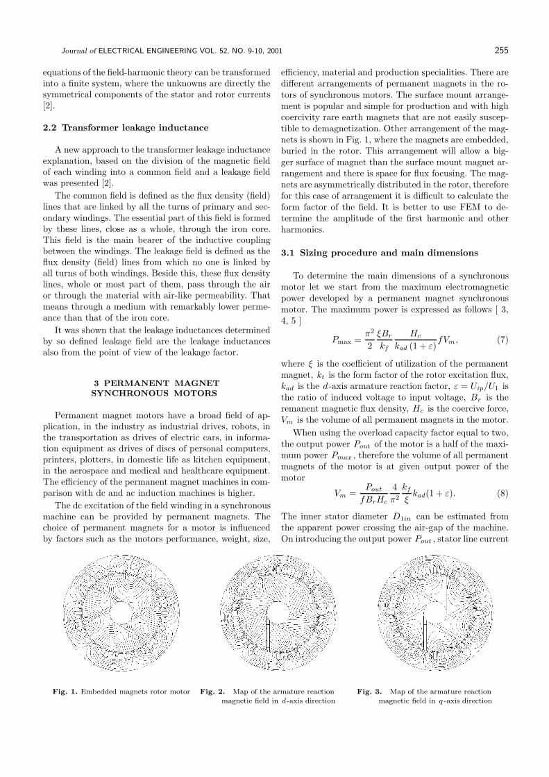
efficiency, material and production specialities. There aredifferent arrangements of permanent magnets in the ro-tors of synchronous motors. The surface mount arrange-ment is popular and simple for production and with highcoercivity rare earth magnets that are not easily suscep-tible to demagnetization. Other arrangement of the mag-nets is shown in Fig. 1, where the magnets are embedded,buried in the rotor. This arrangement will allow a big-ger surface of magnet than the surface mount magnet ar-rangement and there is space for flux focusing. The mag-nets are asymmetrically distributed in the rotor, thereforefor this case of arrangement it is difficult to calculate theform factor of the field. It is better to use FEM to de-termine the amplitude of the first harmonic and otherharmonics.
3.1 Sizing procedure and main dimensions
To determine the main dimensions of a synchronousmotor let we start from the maximum electromagneticpower developed by a permanent magnet synchronousmotor. The maximum power is expressed as follows [ 3,4, 5 ]
Pmax =π2
2
ξBr
kf
Hc
kad (1 + ε)fVm, (7)
where ξ is the coefficient of utilization of the permanentmagnet, kt is the form factor of the rotor excitation flux,kad is the d-axis armature reaction factor, ε = Uip/U1 isthe ratio of induced voltage to input voltage, Br is theremanent magnetic flux density, Hc is the coercive force,Vm is the volume of all permanent magnets in the motor.
When using the overload capacity factor equal to two,the output power Pout of the motor is a half of the maxi-mum power Pmax , therefore the volume of all permanentmagnets of the motor is at given output power of themotor
Vm =Pout
fBrHc
4
π2
kf
ξkad(1 + ε). (8)
The inner stator diameter D1in can be estimated fromthe apparent power crossing the air-gap of the machine.On introducing the output power Pout , stator line current
Fig. 1. Embedded magnets rotor motor Fig. 2. Map of the armature reactionmagnetic field in d -axis direction
Fig. 3. Map of the armature reactionmagnetic field in q -axis direction

256 L. Hruskovic – L’. Klug – L’. Huttner – N. Liptak – F. Valent – L. Borba – L’. Jurcacko: SOLUTION OF PARTIAL PROBLEMS . . .
L (mm)
-0.4
-0.3
-0.2
-0.1
0.0
0.1
0.2
0.3
0.4
0 20 40 60 80 100 120
B (T)n
Fig. 4. Flux density line in the air gap in d -axis direction
-0.8
-0.6
-0.4
-0.2
0.0
0.2
0.4
0.6
0.8
0 20 40 60 80 100 120
B (T)n
L (mm)
Fig. 5. Flux density line in the air gap in q -axis direction
density Am , flux density in the air gap Bg , the product
D21inLi takes the form
D21inLi =
Pout
σp
ε
n1, (9)
where the coefficient σp expresses the electric and mag-netic utilisation of the machine
σp =1
2π2kw1AmBgη cosϕ. (10)
For the rotor with buried permanent magnets asymmet-rically distributed in the rotor, according to Fig. 1, it isdifficult to determine the form factor of the excitationfield kf and the form factor of the armature reactionfield in d - axis direction kfd and the resultant arma-ture reaction factor kad = kfd/kf analytically. Thereforein special asymmetrical cases the FEM modelling of themagnetic fields is used.
Modelling the map of the excitation magnetic field inthe machine on no load condition is also shown in Fig 1.Modelling of the map of the armature reaction magneticfields in the d - axis and q - axis direction is shown in Figs2 and 3, and the normal component of the flux density linein the air gap of the machine in the d - axis and q - axisdirections is shown in the Figs 4 and 5. The coefficientsnecessary to determine the magnetic conditions of themachine are extracted from the lines of the magnetic fluxdensity distribution in the d - axis and q - axis directionby means of Fourier analysis.
3.2 Simulation of dynamic behaviour of themachine
A circuit model of a permanent magnet motor, whichis used for predicting its transient behaviour, can be ob-tained using equivalent circuit representation for perma-nent magnets. The magnetic field produced by the per-manent magnets is created by a field coil which is passedby excitation current If . The field coil inductance isthe common d-axis mutual inductance of the stator Lmd
and the current If is the equivalent magnetizing currentof the permanent magnets, referred to the stator side.The corresponding voltage equations are then similar to
those of a synchronous machine excited by a field coil andequipped with a damper cage winding.
The equivalent field winding is created by a numberof turns Nf and the current is determined from themagneto-motive force F0 , as If = F0/Nf . Let us con-sider the number of turns of the field winding Nf = 1.The mutual inductance of the field winding in the d-axisdirection is determined as Lmd = ΦM/Fad , where ΦM isthe flux of permanent magnets, Fad is the armature reac-tive mmf in d-axes direction. The set of all equations forflux linkages, winding currents and rotor motion for simu-lation and all circuit diagrams in MATLAB/SIMULINKcan be found in [6].
4 PARTIAL PROBLEMS OF LOW–VOLTAGE
ELECTRICAL APPARATUS
In the area of electrical apparatus, theoretical and ex-perimental problems of electrical arc in switching andprotecting low-voltage devices are solved: current limi-tation at short-circuit current breaking, passage throughcurrent zero, design and properties of a deion chamber,subsystems of protection devices, solution of the thermalfield, model of electrical breakdown of small air gap andbreaking process in the deion chamber are presented.
4.1 Time-space distribution of the temperature
The breaking arc, as a short-time thermal source, sup-plies heat into the contact. The heat is transmitted awayfrom the place of its origin (root of the arc) into the con-tact by conduction. The solution of the temperature fieldcomes out from the basic equation for heat conduction
∂ϑ
∂t=
λ
cρ
(
∂2ϑ
∂x2+
∂2ϑ
∂y2+
∂2ϑ
∂z2
)
= a∇2ϑ. (11)
Here are: ϑ - temperature, λ - thermal conductivity, c- specific thermal capacity, ρ - specific density, t - time,x, y, z - co-ordinates, a - temperature conductivity. Thesolution of the time-space distribution is complicated.When it is possible, we better use a simplification andthe task is then solved as a single dimension problem.

Journal of ELECTRICAL ENGINEERING VOL. 52, NO. 9-10, 2001 257
0 1 2 3 4 5 6 7 8 9 100
10
20
30
40
5
10
15
J (K)
t (s)
20
25
Fig. 6. Calculated time behaviour of temperature
In the case of the short-time thermal source as eg
breaking arc, it is possible to use the method of sources[7]. The physical principle of the source method is such,that the process of heat dissipated in a solid body canbe imagined as a sum of elementary heat sources decom-posed in space and time. The influence of an elementaryheat source is given by the function
F (x, x1,t) =b√
4πate− (x − x1)
2
4at (12)
This function is the basic solution of equation (11) andexpresses the temperature in point x , when at the be-ginning, in the point x1 , a heat quantity Q = bcp issupplied, where b is a coefficient, which characterizes theimpulse heat source. For a short time of heat source in-fluence, nearly the whole heat quantity is concentrated inthe surrounding of point x1 .
In our case the contact presents a semi-bordered solidbody and the task can be solved in a single-dimensionfield, with simplifications as follows:
- heat impulse acts at time t = 0 in position x1 ,
- thermal-physical coefficients are constant and they areindependent of temperature
- the Joule losses caused by the current flowing throughthe contact are neglected. For a short-time and smalldimensions cooling of contacts can be neglect. Thisallows for a simpler form of equation
ϑ(x, t) =Q
Sρc√
4πat
e−
(x − x1)2
4at + e−
(x + x1)2
4at
.
(13)
Here is Q - quantity of supplied heat, S - cross -sectionof contact, x1 - place of arc root. This equation shows thesettlement of temperature in a semi-bordered solid afterabsorption of a thermal impulse in place x1 .
In equation (13) we assume that at the beginning thetemperature is equal to zero ϑ(x, 0) = 0. Then the equa-tions are valid both for temperature and temperature rise.
Calculation of temperature distribution has been solvedby equation (13), for copper contacts with dimensions10.5 x 1.5 x 30 mm. The resulting temperature rise-timecurve can be seen in Fig. 6. An important parameterwhich enters the calculations is the performance of theheat source. Its value can considerably influence the finalvalue of temperature.
4.2 Calculation of breakdown voltages in smallair-gaps
Mathematical-physical model of breakdown voltagesin small air-gaps, including the influence of the field emis-sion phenomenon is similar to the described model in [8],which also considers the effect of thermal emission. Phys-ical idea of the model is based on the Towsend’s criterionof the breakdown.
The breakdown voltage Up is easy to calculate fromthe formula
kA
aBUpe
−BViρd
kUp
1 − e
−BViρda
kUp
= ln
(
1 +1
γ∗
)
(14)where A, B, a, k are constants influencing the distributionof electrical field at the cathode and the position and mag-nitude of minimum of Paschen’s curve, d is the distanceof electrodes, Vi potential of ionisation, and p densityof the space between the electrodes. Into the Towsend’scoefficient the field emission effect is also included
γ∗ = γ
(
1 +iaisec
)
(15)
where γ is Towsend’s coefficient without the effect offield emission, ia is the field emission current, and isec
is the current of secondary electrons. The current densityof field emission current ja is determined by the formula
ja = 3.1 × 10⁻⁶ E2
We−6.8× 10⁹ W 1,5
E . (16)
Here W is the work function of the material of the cath-ode and E is the electrical field intensity on the surfaceof the cathode without the effect of the microrelief of thecathode.
The calculation of breakdown voltage Up in depen-dence on the microlength d was realised for air mediumat athmospheric pressure, for W ≈ 4.5 eV, γ = 0.02.Amplification of the electrical field on the surface of cath-ode by microrelief was considered, according to [9] in therange 20÷100. Calculated relations can be seen in Fig. 7for amplification of field 20, 60, 100 (full line).
From Fig. 7 it is seen, that the breakdown voltageexpressively depends on the amplification of electricalfield by the microrelief of cathode surface. This explain

258 L. Hruskovic – L’. Klug – L’. Huttner – N. Liptak – F. Valent – L. Borba – L’. Jurcacko: SOLUTION OF PARTIAL PROBLEMS . . .
20
60100
0 5 10 15 20d ( m)m
200
300
400
100
(V)Up
Fig. 7. Relation of breakdown voltage vsdistance of electrodes atdifferent amplification of field
Fig. 8. Design of arrangement of contact and extinguishing sub-systems of MCB
the expressive leakage of measured values shown in [10].Calculation results confirm experimental test results. Forsmall distances of electrodes and high amplification offield, the breakdown voltages can achieve tens of volts.
The results of experiments and the results of calcu-lation of the breakdown voltage of microdistances on asimple mathematical model proved that electrical break-down can be caused by voltages of the range of tens ofvolts. The decrease in the breakdown voltage is expres-sively influenced by field emission and by the microreliefof the cathode. The breakdown can have an avalanche, orevolutionary character. The obtained results contributeto the explanation of arc movement in the quenching sys-tem of low voltage contact breakers.
4.3 Development of arc in MCB in extremelydifficult conditions of breaking process
An important parameter, characterising the switchingproperties of a miniature circuit breaker (MCB), is itsswitching ability. The following part of contribution isdealing with problems of the switching process in MCBwhile switching off short-circuit current.
The requirement on the breaking process is distinct: itis important for a MCB (from the very beginning of short- circuit current) to start separating contacts as soon aspossible and to push-out the arc from the place of its ori-gin into a quenching chamber, to remain there until theinterruption of current. Current limiting effect of MCB is
inevitable [11]. Breaking-up a short circuit current up to6 kA by standard MCB makes no problems, but reachinga high value of breaking capacity 10 (15) kA MCB withhigh rated current (63 A), lowered sensitivity of electro-magnetic release (tripping characteristics C, D) and mod-ular scales with width of module 17.5 mm is in fact a verydifficult task and switching process is extremely difficult.
The basic limiting factors of breaking capacity, ie ther-mal stress of the deion chamber [12], duplicating arcingbetween contacts or under the extinction chamber, causedby breakdown of arc voltage or recovery voltage [13], pres-sure stress [14], more difficult testing conditions (verify-ing of flow of ionised gases through potential grating),result in a slow movement or even temporary stopping ofthe moving arc in the area of its development with ther-mal overload and erosion of contact system parts withresulting effect of great value JI, eventually dysfunctionof MCB. That is the reason why it is inevitable to usea construction layout of arc development (AD) which isnot a limiting factor of the breaking process and allowsreaching the required breaking capacity 10 (15) kA.
According to the orientation of the arc jump fromthe burn-off part of the moving contact on arc runner inMCB, by European producers is used basic constructionof AD with directing the jump area on an external arcrunner, Fig. 8.
The quick AD without negative phenomena is stronglyinfluenced by the phase of arc developing velocity andcontinuity of arc movement from the place of contact andin the junction region. The solution of given problemsresulted into a new construction lay-out of area of the arcdevelopment with outstanding properties in the phase ofAD.
Fig. 9. Oscillogram of 10 kA short-circuit breaking with adjustableMCB (upper trace - arc voltage, lower trace - arc current) 100 V/d,
2.5 kA/d, 2 ms/d.
A record of short-circuit current breaking 10 kA ad-justed MCB in a testing circuit with short-circuit gener-ator is in Fig. 9. The time voltage curve on MCB andcurrent flow in MCB were recorded by digital oscillo-scope Tektronix 2430 A. Experiments and oscillogramsprove reaching an extremely short time of AD in MCB.The typical time is 0.5 ms. It is also inevitable for MCB,

Journal of ELECTRICAL ENGINEERING VOL. 52, NO. 9-10, 2001 259
LOAD
ACTIVE FILTER
SOURCE
uf
Fig. 10. Block schematics of the series active filter (SAF).
from aerodynamic point of view, to have a well devel-oped extinction system [11] with working circulation flowof environment. This condition is well fulfilled by a deionchamber with a separated reversed circulation flow in-side the deion chamber [15], which allows maximal use ofspace for the extinction chamber and thus reaching of itsgreater thermal capacity.
5 QUALITY OF POWER SUPPLIED FROM
ELECTRIC DISTRIBUTION NETWORK
Industrial semiconductor power equipment are in itsnature non-linear units. Supplied from the network theydemand non-harmonic currents, thus deforming the curveof the supply voltage. Their switching mode of workcauses RFI (radio frequency interference). Because theabove influences are of dynamic character, the situationin the distribution network calls urgently for compensat-ing equipment, able to improve its power factor (cosϕ),
to filter higher harmonics and to symmetrize any non-
symetric loads. All this shall be done not only in steady
states, but also in transient states. The solution has been
found in active filters
A series type active filter (SAF) is the best one for
compensation goals, Fig. 10. For the scheme we can write
according to the 1st Kirchhoff law for instantaneous cur-
rent values:
is = iI + if (17)
A parallel type active filter (PAF) is a controlled current
source. It injects current into the input to the load. If the
current is equal to the sum of all higher harmonics that
are present in the source current, higher current harmon-
ics may be compensated (filtered). Also, if the current
generates the reactive component of the 1st harmonics,
reactive power may be compensated and the power factor
improved. This principle can be described by the follow-
ing equations:
iI = ip + iq + ih if = −iq − ih (18)
so that
iss = ip + iqq + ih − iq − ih is = ip (19)
where index p indicates an active current component, q
indicates idle, reactive component, h indicates current
higher harmonics The influence of the PAF was exam-
ined in two options, and verified by both physical and
simulation experiments.
T2
D2
Lfb
VoltageRegulator
Control Algorithmof Active Filter
Dynamic HysteresisCurrent Control
NonlinearLoad
Lf a
Rf a Cf a
Cf b
Cf cLf c
Rf b
Rf c
PASSIVEFILTER
T4 T6
D4 D6
ACTIVE FILTER
+
C2
uc2
uc1 +
C1
T1
D1
T3 T5
D3 D5
SOURCE
T1 T2 T3 T4 T5 T6
ica
icb
icc
ic0
ia
ibic
i0
isa
isb
isc
is0
e
ifb
if a
if c
ib
ia
ic
ua ub uc
ploss
i*
ca
i*
cb
i*
cc
Fig. 11. 3-Phase/4-wires Parallel Active Filter.

260 L. Hruskovic – L’. Klug – L’. Huttner – N. Liptak – F. Valent – L. Borba – L’. Jurcacko: SOLUTION OF PARTIAL PROBLEMS . . .
-30
0
30
60
90
120
150
-150
-120
-90
-60
-30
0
30
4.0 4.8 5.6 6.4 7.2 8.0
time (10-2s)
iL1 (A) iLfa (A)
ipower
iload
ifilter
Fig. 12. Instant values of the current in system network-filter-load”, (load - 3 phase bridge rectifier)
-20.0
-16.0
-12.0
-8.0
-4.0
0.0
4.0
-200
-160
-120
-80
-40
0
40
4.0 4.8 5.6 6.4 7.2 8.0
time (10-2s)
iL1 (A)
ipower a
iload a
ifilter a
upower a
P10 (102V)
Fig. 13. Instant values of the current in phases a, b, c in systemnetwork-filter-load”, (load - 3 phase bridge rectifier)
PAF2-phase
3-pase/2-phase
iaua
ibub
ic
i =0nl2
inl1is1
if 1 if 2
is2
uc
3 110kV/50Hz´ 2 25kV/50Hz´
Fig. 14. Electric traction 3-phase parallel active filter
5.1 The 3-phase / 4-wires PAF
The power circuitry (Fig. 11) consists of a 2-quadrantconverter working with one voltage polarity and two
current polarities. Principally it works as a current
source controlled by immediate reactive power. The block
scheme of the control circuitry for the 3-phase 4-wires
PAF performs a control assuring an instant active 3-phase
power to be supplied from the network. If the network
voltages are harmonic and the network system is sym-
metrical, this type of control assures that the currents
supplied from the network into the system ”filter-load ”
are harmonic too, regardless of the load type. The cor-
rectness of the method is approved by simulation experi-
ments, Fig. 12, Fig. 13 [17].
5.2 1-phase active filter for the traction network
25kV / 50 Hz
Supplying 1-phase traction systems from 3-phase dis-
tribution network is a special task. A scheme using a 2-
3-phase /2-phasetransformer
a
b
c
T1aT1b
L1L2
VT1
VT2
VT3
VT4
uc1a
uc1b
us1
us2
+
+
if 1'if 2'
T3 T2
is1
is2
ipf 2
ipf 1
if 1
if 2
inl1
inl2
nonlinearload 1
nonlinearload 2
passivefilters
Fig. 15. 3-phase parallel active filter wit a pull-down transformer

Journal of ELECTRICAL ENGINEERING VOL. 52, NO. 9-10, 2001 261
inl2
us2
Fig. 16. Reaching a symmetry (50 V/div, 2 A/div, 5 ms/div)
phase active filter is in Fig. 14. Using the active filter is
motivated
- by severe unsymmetrical load of 3-phase supplying
network in spite of the presence of a special supplying
transformer,
- by higher current harmonics and
- by degradation of the power factor in non-compensated
traction system.
Application of 2-phase active filter in a system shownin Fig. 15 was investigated. Measured oscillographs fromthe realised physical model are in Fig. 16 (scheme param-eters are the same as in Fig. 14 and Fig. 15) [16].
In the experiment phase 1 was loaded by a non-controlled rectifier (presenting a traction rectifier in arailway wagon), while phase 2 was unloaded. The Fig-ures display symmetrical (!) load of the 3-phase supplyingnetwork and supplied network phase current vs time ofthe 1st harmonics for a non-symmetrical and non- linearload. Simulation experiments allow to calculate (for thisscheme and 1245 kVA) an increased power factor from0.64 up to 0.96.
5.3 4-quadrant converter
Another way to solve the quality of supplied electricalenergy for electronically controlled appliances is the useof a converter taking no higher harmonics and no reactivepower from the supplying network. Say, a 4-quadrantconverter is the case. It loads the network by almostharmonic current, in phase with the network voltage.
The subject of investigation was a 4-quadrant con-verter with PWM, supplied from secondary of a tractiondrive transformer. Figure 17 gives a scheme of a converterwith a condenser (as a source of energy) coupled in par-allel to the DC side [17].
A 4-quadrant converter is able to work in all 4 quad-rants of the phase angle between the source voltage andcurrent, ie it is able to change the phase shift of the sup-plied current with respect to the supply voltage, control-ling the idle, reactive power. This scheme allows for re-cuperative braking, ie changing the kinetic energy of atraction vehicle into electric energy and returning it backto the distribution 110 kV network through the tractionsupplying network and supplying plant.
Psource
Ploss
Pload
C
D1 T1 D3 T3
D4 T4T2D2
Lvi
s
uc
id
e
Fig. 17. The scheme of a 4 quadrant converter
The heart of a converter of this type is a current con-troller. It controls the load current by switching semicon-ductor valves so that the load current shape copies theshape of a reference current.
The properties of the system controlled by differenttypes of controllers (with different dynamic behaviours)and systems with vector control of the 4-quadrant con-verter were analysed by simulation experiments. The gen-eral goal was to achieve a sinusoidal shape of the supplied

262 L. Hruskovic – L’. Klug – L’. Huttner – N. Liptak – F. Valent – L. Borba – L’. Jurcacko: SOLUTION OF PARTIAL PROBLEMS . . .
1.50
1.55
1.60
1.65
1.70
1.75
1.80
1.85
1.90
1.95
2.00
-1.50
-1.20
-0.90
-0.60
-0.30
0.00
0.30
0.60
0.90
1.20
1.50
0.675 0.743 0.811 0.878 0.946 1.013time (10 s)
-1
eis
u (10 V)c
3i (10 A)s
3
uc
Fig. 18. Time dependence of is , Us and e in a 4 quadrant con-verter at a switching frequency fc = 1kHz
-2.30
-1.84
-1.38
-0.92
-0.46
0.00
0.46
0.92
1.38
1.94
2.30
-1.80
-1.44
-1.08
-0.72
-0.36
0.00
0.36
0.72
1.08
1.44
1.80
0.675 0.743 0.811 0.878 0.946 1.013time (10 s)
-1
eis
e (10 V)2
i (10 A)s
3
Fig. 19. Instant values of the current in phases a, b, c in systemnetwork-filter-load”, (load - 3 phase bridge rectifier)
network current, in phase with the supply voltage, abil-ity to keep the voltage in the DC intermittent circuit ata reference average value (this is a controlling conditionof the converter).
Individual controlling methods are illustrated in Fig.18(circuit parameters of the system using a hysteresis con-troller with constant switching frequency 1 kHz andpower of traction motors equal to 1 MW ), and in Fig.19(circuit parameters of the system using the vector control,harmonic modulating voltages and power of traction mo-tors equal to 1 MW).
The results of all the experiments allow us to say thatthe system is perspective for optimization of power supplyfrom the distribution AC network.
6 CONCLUSION
The results published here are contributions of theDepartment staff members to the progress of knowledgein the field of electric machines, apparatus, drives andpower electronics. A more detailed description of individ-ual problems is not possible with respect to the range andcharacter of this paper. We refer the reader to the nextlist of articles published by our authors. A wide rangeof topics were solved on demand of industry and to itssupport.
Acknowledgement
We gratefully acknowledge that the results presentedhere were solved as partial goals of the research tasksVEGA No 4293, VEGA No 1/7604/20, VEGA No 1/8127/01 and IPVT/6/98.
References
[1] HRUSKOVIC, L. : A contribution to the Linear Theory ofInduction Machines, Elektrotechnicky casopis No. 3 (1960),139-146. (in Slovak)
[2] HRUSKOVIC, L. : Equations and Leakage Reactances of Trans-formers and Induction Machines, Slovak University of Technol-
ogy, 2000. (in Slovak)
[3] J. F. GIERAS—M. WING : Permanent Magnet Motor Tech-
nology, Marcel Dekker, Inc. New York, 1997.
[4] I. L. OSIN—V. L. KOLESNIKOV—F. M. JUFEROV : Sinchron-
nye mikrodvigateli s postojannymi magnitami, Energija, Moskva,
1976.
[5] R. MAGUREANU—N. VASILE : Servomotoare fara perii tip
sincron, Editura Tehnica, Bucuresti, 1990. (in Romanian)
[6] CH. M. ONG : Dynamic Simulation of Electric Machinery using
MATLAB/SIMULINK, Prentice Hall Ptr, New Jersy, 1998.
[7] KARSLOU, G.—JAEGER, D. : Teploprovodnost tverdych tel,
Nauka, Moskva, 1964.
[8] VALENT, F. : Current Zero Phenomena at Low-voltage Cir-
cuits Breaking, Thesis EF STU, Bratislava, 1989. (in Slovak)
[9] SLIVKOV, I. N.—MICHAJLOV, V. I.—SIDOROV, N. I.—NAS-
TJUCHA, A. I. : Elektriceskij proboj a razrjad v vakuume,
Atomizdat, Moskva, 1966. (in Russian)
[10] TAJEV, I. S.—KUZNECOV, V. N. : Probivnyje naprjazenija
mikropromezutkov v vozduche, Elektrotechnika (1975), 54-57.
[11] VALENT, F.—HUTTNER, L.—JURCACKO, L. : Influence of
Extinction Device of the Low-voltage Circuit Breaker on the
Limiting of Short-circuit Current, Proc. of the Switching arc
Phenomena, L’odz Poland, 1993, pp. 85-89.
[12] HUTTNER, L. : Contribution to the Design of Extinguish-
ing Chamber of MCB Proc., XII- th Symposium on Physics of
switching Arc (1996), 98-102, Brno.
[13] VALENT, F. : Influence of Cathode Sheet and Temperature
on the After-arc Breakdown Voltage of AC Low-voltage Switch
gears, Elektrotechnicky obzor 79 No. 5 (1990), 271-276. (in Slo-
vak)
[14] JURCACKO, L. : The Time Pressure Curve During Breaking
of the Short-circuit Current in the Miniature Circuit Breaker as
a Diagnostic Element of Contact Activities, Proc. XI th Sympo-
sium on Physics of switching arc, 1994, Brno, pp 109-112.
[15] JURCACKO, L. : Deion Chamber for Electrical Switch Gears
of Low-voltage, Patent No 277843, 1995, SK. (in Slovak)
[16] VRANKA, M. : Design of 1-Phase Active Filter for Higher Har-
monics Elimination, Electric Traction Supply Network 25kV,
50Hz. Final project of Engineering study, KESP FEI STU,
Bratislava, 2000 (in Slovak).
[17] BOROS, T. : 4-Quadrant Converter, Final project of Engineer-
ing study, KESP FEI STU, Bratislava, 2000. (in Slovak)
[18] CERNAN, P. : Design of 3-Phase Active Filter, Final project of
Engineering study, KESP FEI STU, Bratislava, 2000. (in Slovak)
Received 25 May 2001

Journal of ELECTRICAL ENGINEERING VOL. 52, NO. 9-10, 2001 263
Ladislav Hruskovic (Prof, Ing, DrSc) was born in DolneHamre, Slovakia in 1929. He received his Ing degree in Elec-trical Engineering from the Faculty of Electrical Engineeringof the Slovak University of Technology, Bratislava, in 1952,the PhD degree in 1958, and the DrSc degree in 1988. He isauthor of text books in the field of electrical machines andelectrical machines for controlled drives as well as of papers inthe field-harmonic theory of the induction machine, in the the-ory of leakage reactances of electrical machines, single-phaseinduction machines and rotating transformers.
L’udovıt Klug (Prof, Ing, PhD) was born in Komarno, in1935. He received his Ing degree in Electrical Engineering fromthe Faculty of Electrical Engineering of the Slovak Universityof Technology, Bratislava, in 1959, the PhD degree in 1973,Prof. degree in 1997. He is author of many publications in thefield of electrical machines, permanent magnet machines, gen-eralized theory of machines, modeling of the magnetic fields inthe machines by FEM, electromagnetic design of the machinesand their simulation.
L’udovıt Huttner (Doc, Ing, PhD) was born in Bratislava,Slovakia, 1946. He graduated from the Faculty of ElectricalEngineering, Slovak University of Technology, Bratislava, in1969. He gained the PhD degree in Electrical Machines andDevices, in 1988. At present he is Associate Professor and headof the department of Electrical Machines and Devices. Themain field of his research and teaching activities are switchingand protective low-voltage apparatus and using of computersin education.
Ferdinand Valent (Doc, Ing, PhD) was born in Kokavanad Rimavicou, Slovakia, 1940. He graduated from the Fac-ulty of Electrical Engineering, Slovak University of Technol-
ogy, Bratislava, in 1963. He gained the PhD degree in Electri-
cal Machines and Devices, in 1990. At present he is Associate
Professor of the department of Electrical Machines and De-vices. The main field of his research is the theory of electric
arc, switching processes and development of switch and pro-
tective low-voltage apparatus.
Neitus Liptak (Doc, Ing, PhD) was born in Ruzomberok,
Slovakia, 1933. He graduated from the Faculty of Electrical
Engineering, Slovak University of Technology, Bratislava, in1958 . He gained the PhD degree in Electrical Machines and
Devices, in 1980. At present he is retired but still works for
the Department of Electrical Machines and Devices. The main
field of his research activities are modern methods in control
drives and CAMS.
Ladislav Borba (Ing, PhD) was born in Bratislava, Slo-
vakia, in 1943. He graduated from the Faculty of ElectricalEngineering, Slovak University of Technology, Bratislava, in
1967. He gained the PhD degree in Electrical Machines and
Devices, in 1985. At present he is staff member of the de-
partment of Electrical Machines and Devices. The main fieldof his research activities are power semiconductor converters
and systems for electric controlled drives.
Ludovıt Jurcacko (Ing) was born in Bratislava, Slovakia,
1947. He graduated from the Faculty of Electrical Engineer-
ing, Slovak University of Technology, Bratislava, in 1971. At
present he is staff member of the Department of Electrical Ma-
chines and Devices. The main field of his research activitiesare problems of breaking process of low-voltage electric appa-
ratus and development of switch and protective low-voltage
apparatus.
Co-foundators:Department of Automatic Control SystemsFEI STU, Department of Control and Au-tomation FEI STU Department of ChTF STU,
PPA CONTROLL, a.s.
www.atpjournal.sk
Published by HMH s.r.o
Editor in Chief: Anton GererEditorial Board of AT&P Journal:
prof. Ing. Alexık Mikulas, CSc., FRI ZU, doc. Ing. Dvoran Jan, PhD.,CHtF STU, prof. Ing. Frankovic Baltazar, DrSc., SAV, doc. Ing.Hradocky Ladislav, CSc., SjF TU, prof. Dr. Ing. Hulko Gabriel, DrSc.,SjF STU, prof. Ing. Jurisica Ladislav, CSc., FEI STU, doc. Ing.Kachanak Anton, CSc., SjF STU, prof. Ing. Madarasz Ladislav, Phd.,FEI TU, prof. Ing. Malindzak Dusan, CSc., BERG TU, doc. Ing.Meszaros Alojz, CSc., ChtF STU, prof. Ing. Mikles Jan, DrSc., ChtFSTU, prof. Ing. Moravcık Oliver, DrSc., MtF STU, Ing. MurancanLadislav, PPA Controll a.s. Bratislava, prof. Ing. Murgas Jan, CSc.,FEI STU, prof. Ing. Sarnovsky Jan, CSc., FEI TU, prof. Ing. Skyva
Ladislav, DrSc., FRI ZU, prof. Ing. Smiesko Viktor, CSc., FEI STU,
doc. Ing. Sturcel Jn, CSc., FEI STU, prof. Ing. Taufer Ivan, DrSc.,Univerzita Pardubice, prof. Ing. Vesel Vojtech, DrSc., FEI STU, prof.
Ing. Zalman Milan, PhD., FEI STU, Ing. Bartosovic Stefan, director of
ProCS, s.r.o., Sala, Ing. Bodo Vladimır, CSc., director of AXESS, spol.s r.o., Ing. Cisko Jozef, SPEL-PROCONT, authorized vendor, Allen-Bradley Hedera Julian, general director of HONEYWELL, spol. s r.o.,Ing. Horvth Tom, director of HMH, s.r.o., Ing. Kollarik L’ubomır, Ing.Krause Rudolf, general director of REGULA, a.s. Kosice, Ing. Petergac
Stefan, president of directorium of Datalan Group, Ing. Prevaj Jozef,director of Fisher-Rosemount Slovakia, s.r.o., Ing. Sykorcin Pavol, KeyAccount Manager, Siemens, s.r.o., Ing. Valach Vladimır, general di-rector of ABB Elektro, s.r.o., Ing. Varga Alexander, CSc., director ofMICROSTEP, spol. s r.o.


![COMPARISONOFHONEYBEEMATINGOPTIMIZATION …iris.elf.stuba.sk/JEEEC/data/pdf/3_113-01.pdf · 2013. 5. 22. · system stability enhancement through improved damping of power swings [12]](https://img.pdfslide.net/doc/110x75/603e07791beee513e52b6291/comparisonofhoneybeematingoptimization-iriselfstubaskjeeecdatapdf3113-01pdf.jpg)