Embed Size (px)
Citation preview
adjusted for the 10 unit grid
DO NOT REMOVE PANELS FROM THE CARTON UNTIL YOU HAVE READ THESE INSTRUCTIONS IN THEIR ENTIRETY. LOCATE HARDWARE ACCESSORY KITS THAT SHIPPED SEPARATELY.
1.0 GENERAL
1.1 Product Description
SoundScapes® Shapes Acoustical Clouds are flat fiberglass panels designed to be installed in one of three suspension systems. There are 10 standard panel options that come in a variety of shapes and three nominal sizes: 4' x 4', 4' x 6', and 4' x 8'. SoundScapes Shapes FastShip™ Acoustical Clouds are flat fiberglass panels available in nominal 4' x 4' sizes.
SoundScapes Shapes are designed to be suspended with Armstrong® ceilings accessory kits and are engineered for use in seismic areas only when indicated components are used and installed in accordance with these installation instructions.
1.2 Materials and Finishes
SoundScapes Shapes panels are made from fiberglass and finished on the front surface and four sides with DuraBrite® acoustically transparent membrane. The back of the panel is unfinished with an embedded metal extrusion for use with the three Armstrong® ceilings suspension systems.
There are seven standard color options for the finished panels. See Section 4.0 on page 11 for panel touch-up options. Field painting will void the product warranty.
SoundScapes Shapes Quick Ship panels are made from fiberglass and finished front and back with an acoustically transparent membrane. The sides of the panels are painted. The standard color is white. Field painting will void the product warranty.
1.3 Design Consideration for Sag
SoundScapes Shapes maintain a natural sag that may be noticeable when installed 6" or less apart. Deflection up to 1/8" has been documented in some cases.
Working with Fiberglass Products
MAN-MADE VITREOUS FIBER CEILING PANELSWARNING THIS PRODUCT CONTAINS MAN-MADE
VITREOUS FIBERS. POSSIBLE CANCER AND RESPIRATORY TRACT HAZARDS. CAN CAUSE TEMPORARY RESPIRATORY, SKIN, AND EYE IRRITATION.
Precautionary Measures: During the installation be certain that the work site is well ventilated, and avoid breathing dust. If high dust levels are anticipated during installation such as with the use of power tools, use appropriate NIOSH designated dust respirator. All power cutting tools must be equipped with dust collectors. Avoid contact with skin or eyes. Wear long-sleeve, loose-fitting clothes, gloves, and eye protection.
First Aid Measures: If contact occurs, flush eyes and skin irritation with plenty of water for at least 15 minutes, and remove contaminated clothing. After installing material, wash with warm water and mild soap. Wash work clothes separately from other clothing. Rinse washer thoroughly. Refer to Armstrong Ceilings MSDS (which includes information on established occupational exposure limits) which are available from Armstrong Ceilings or your employer.
1.4 Storage and Handling
The ceiling panel components shall be stored in a dry interior location and shall remain in original cartons prior to installation to avoid damage. The cartons shall be stored in a flat, horizontal position. Save the carton cardboard insert for potential use during installation as a guide for hanging the panels. The panels should not be removed from their carton until the suspension system is ready. Proper care should be taken when handling panels to avoid damage and soiling, particularly with panel edges and the surface of color panels.
Proper care should be taken to locate the hardware accessory kits shipped separately from the panels.
SoundScapeS® Shapes Acoustical Cloudsassembly and Installation Instructions
2
1.5 Temperature During Installation
The product can be installed where the temperature is between 40°F (4°C) and 120°F (49°C). It cannot be used in exterior applications, where standing water is present, or where moisture will come in direct contact with the panel.
1.6 Fire Performance
SoundScapes® Shapes, as with other architectural features located in the ceiling plane, may obstruct or skew the existing or planned fire sprinkler water distribution pattern, or possibly delay the activation of the fire sprinkler or fire detection system. Designers and installers are advised to consult a fire protection engineer, NFPA 13, and their local codes for guidance on the proper installation techniques where fire detection or suppression systems are present.
2.0 COMPONENTS
2.1 Panel Shapes
Panels come in 10 different sizes and shapes. See data sheet BPCS-3867 for exact product dimensions. Panels are flat but may exhibit some natural deflection based on installation details.
2.2 Suspension Systems
There are three types of suspension system options for use with SoundScapes Shapes. Panels can be suspended individually from the deck with aircraft cable, individually direct-attached to drywall with clips, or suspended as a group from the deck with a combination of frames, hooks, and cables.
The following section will describe each option and its installation procedures in more detail.
3.0 INSTALLATION
3.1 General
Before opening the panel carton, be sure to locate the hardware accessory kits needed for installation that were shipped separately.
SoundScapes Shapes may require two people to align and install each panel safely. DO NOT REMOVE THE PANELS FROM THEIR CARTON until the appropriate suspension system method has been prepared and is ready to accept the panels for installation.
Panels cannot be used to support any other material. The suspension system chosen must be fastened to the structure and cannot be hung from any commercial ceiling system. SoundScapes Shapes are not approved for exterior application.
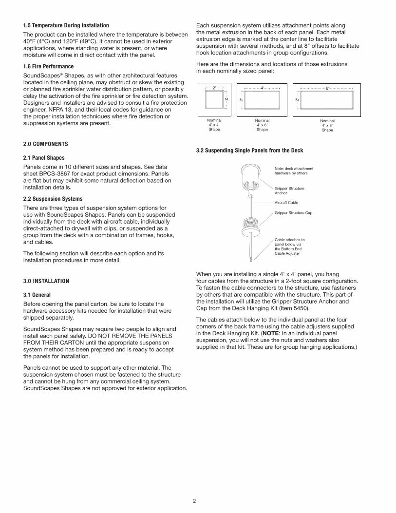
Each suspension system utilizes attachment points along the metal extrusion in the back of each panel. Each metal extrusion edge is marked at the center line to facilitate suspension with several methods, and at 8" offsets to facilitate hook location attachments in group configurations.
Here are the dimensions and locations of those extrusions in each nominally sized panel:
2'
2'
4'
2'
6'
2'
Nominal 4' x 4' Shape
Nominal 4' x 6' Shape
Nominal 4' x 8' Shape
3.2 Suspending Single Panels from the Deck
Gripper StructureAnchor
Gripper Structure Cap
Note: deck attachment hardware by others
Aircraft Cable
Cable attaches topanel below via the Bottom End Cable Adjuster
When you are installing a single 4' x 4' panel, you hang four cables from the structure in a 2-foot square configuration. To fasten the cable connectors to the structure, use fasteners by others that are compatible with the structure. This part of the installation will utilize the Gripper Structure Anchor and Cap from the Deck Hanging Kit (Item 5450).
The cables attach below to the individual panel at the four corners of the back frame using the cable adjusters supplied in the Deck Hanging Kit. (NOTE: In an individual panel suspension, you will not use the nuts and washers also supplied in that kit. These are for group hanging applications.)
3
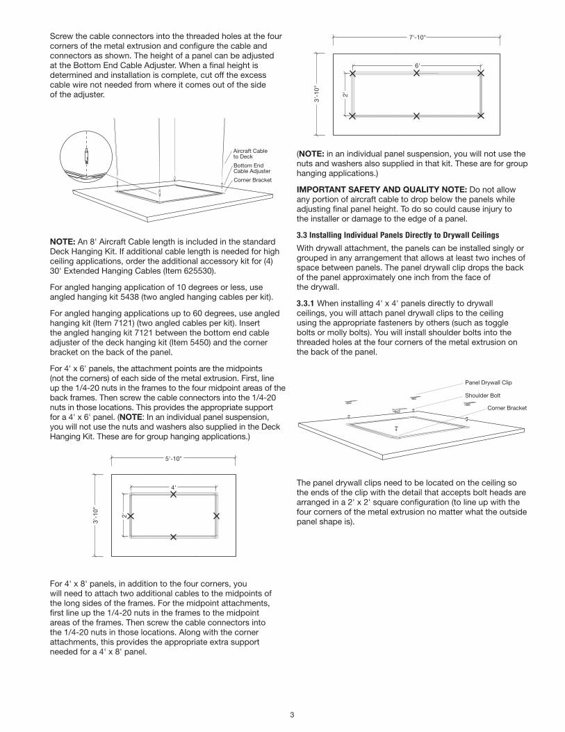
Screw the cable connectors into the threaded holes at the four corners of the metal extrusion and configure the cable and connectors as shown. The height of a panel can be adjusted at the Bottom End Cable Adjuster. When a final height is determined and installation is complete, cut off the excess cable wire not needed from where it comes out of the side of the adjuster.
Aircraft Cableto Deck
Bottom EndCable Adjuster
Corner Bracket
NOTE: An 8' Aircraft Cable length is included in the standard Deck Hanging Kit. If additional cable length is needed for high ceiling applications, order the additional accessory kit for (4) 30' Extended Hanging Cables (Item 625530).
For angled hanging application of 10 degrees or less, use angled hanging kit 5438 (two angled hanging cables per kit).
For angled hanging applications up to 60 degrees, use angled hanging kit (Item 7121) (two angled cables per kit). Insert the angled hanging kit 7121 between the bottom end cable adjuster of the deck hanging kit (Item 5450) and the corner bracket on the back of the panel.
For 4' x 6' panels, the attachment points are the midpoints (not the corners) of each side of the metal extrusion. First, line up the 1/4-20 nuts in the frames to the four midpoint areas of the back frames. Then screw the cable connectors into the 1/4-20 nuts in those locations. This provides the appropriate support for a 4' x 6' panel. (NOTE: In an individual panel suspension, you will not use the nuts and washers also supplied in the Deck Hanging Kit. These are for group hanging applications.)
hanging point
CL of slot
3'-1
0"3'
-10"
3'-1
0"
2'
2'
2'
4'
2'
6'
3'-10"
5'-10"
7'-10"
panel edge
larger panels require additional hanging points at centerFor 4' x 8' panels, in addition to the four corners, you
will need to attach two additional cables to the midpoints of the long sides of the frames. For the midpoint attachments, first line up the 1/4-20 nuts in the frames to the midpoint areas of the frames. Then screw the cable connectors into the 1/4-20 nuts in those locations. Along with the corner attachments, this provides the appropriate extra support needed for a 4' x 8' panel.
hanging point
CL of slot
3'-1
0"3'
-10"
3'-1
0"
2'
2'
2'
4'
2'
6'
3'-10"
5'-10"
7'-10"
panel edge
larger panels require additional hanging points at center
(NOTE: in an individual panel suspension, you will not use the nuts and washers also supplied in that kit. These are for group hanging applications.)
ImpORTANT SAfETy ANd QuAlITy NOTE: Do not allow any portion of aircraft cable to drop below the panels while adjusting final panel height. To do so could cause injury to the installer or damage to the edge of a panel.
3.3 Installing Individual Panels Directly to Drywall Ceilings
With drywall attachment, the panels can be installed singly or grouped in any arrangement that allows at least two inches of space between panels. The panel drywall clip drops the back of the panel approximately one inch from the face of the drywall.
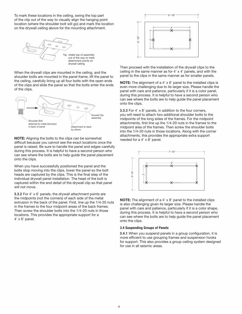
3.3.1 When installing 4' x 4' panels directly to drywall ceilings, you will attach panel drywall clips to the ceiling using the appropriate fasteners by others (such as toggle bolts or molly bolts). You will install shoulder bolts into the threaded holes at the four corners of the metal extrusion on the back of the panel.
Panel Drywall Clip
Shoulder Bolt
Corner Bracket
The panel drywall clips need to be located on the ceiling so the ends of the clip with the detail that accepts bolt heads are arranged in a 2' x 2' square configuration (to line up with the four corners of the metal extrusion no matter what the outside panel shape is).
4
To mark these locations in the ceiling, swing the top part of the clip out of the way to visually align the hanging point location (where the shoulder bolt will go) and mark the location on the drywall ceiling above for the mounting attachment.
Drywall Clipassembly
Shoulder Boltattached to metal extrusion in back of panel
Tip: rotate top of assembly out of the way to mark attachment points on drywall ceiling
Attachment to deck by others
Tip: rotate top of assembly out of the way to mark attachment points on drywall ceiling
When the drywall clips are mounted in the ceiling, and the shoulder bolts are mounted in the panel frame, lift the panel to the ceiling, carefully lining up all four bolts with the open ends of the clips and slide the panel so that the bolts enter the ends of the clips.
Drywall Clipassembly
Shoulder Boltattached to metal extrusion in back of panel
Tip: rotate top of assembly out of the way to mark attachment points on drywall ceiling
Attachment to deck by others
NOTE: Aligning the bolts to the clips can be somewhat difficult because you cannot see the exact locations once the panel is raised. Be sure to handle the panel and edges carefully during this process. It is helpful to have a second person who can see where the bolts are to help guide the panel placement onto the clips.
When you have successfully positioned the panel and the bolts stop moving into the clips, lower the panel so the bolt heads are captured by the clips. This is the final step of the individual drywall panel installation. The head of the bolt is captured within the end detail of the drywall clip so that panel will not move.
3.3.2 For 4' x 6' panels, the drywall attachment points are the midpoints (not the corners) of each side of the metal extrusion in the back of the panel. First, line up the 1/4-20 nuts in the frames to the four midpoint areas of the back frames. Then screw the shoulder bolts into the 1/4-20 nuts in those locations. This provides the appropriate support for a 4' x 6' panel.
hanging point
CL of slot
3'-1
0"3'
-10"
3'-1
0"
2'
2'
2'
4'
2'
6'
3'-10"
5'-10"
7'-10"
panel edge
larger panels require additional hanging points at centerThen proceed with the installation of the drywall clips to the
ceiling in the same manner as for 4' x 4' panels, and with the panel to the clips in the same manner as for smaller panels.
NOTE: The alignment of a 4' x 6' panel to the installed clips is even more challenging due to its larger size. Please handle the panel with care and patience, particularly if it is a color panel, during this process. It is helpful to have a second person who can see where the bolts are to help guide the panel placement onto the clips.
3.3.3 For 4' x 8' panels, in addition to the four corners, you will need to attach two additional shoulder bolts to the midpoints of the long sides of the frames. For the midpoint attachments, first line up the 1/4-20 nuts in the frames to the midpoint area of the frames. Then screw the shoulder bolts into the 1/4-20 nuts in those locations. Along with the corner attachments, this provides the appropriate extra support needed for a 4' x 8' panel.
hanging point
CL of slot
3'-1
0"3'
-10"
3'-1
0"
2'
2'
2'
4'
2'
6'
3'-10"
5'-10"
7'-10"
panel edge
larger panels require additional hanging points at center
NOTE: The alignment of a 4' x 8' panel to the installed clips is also challenging given its larger size. Please handle the panel with care and patience, particularly if it is a color shape, during this process. It is helpful to have a second person who can see where the bolts are to help guide the panel placement onto the clips.
3.4 Suspending Groups of Panels
3.4.1 When you suspend panels in a group configuration, it is more efficient to use grouping frames and suspension hooks for support. This also provides a group ceiling system designed for use in all seismic areas.
5
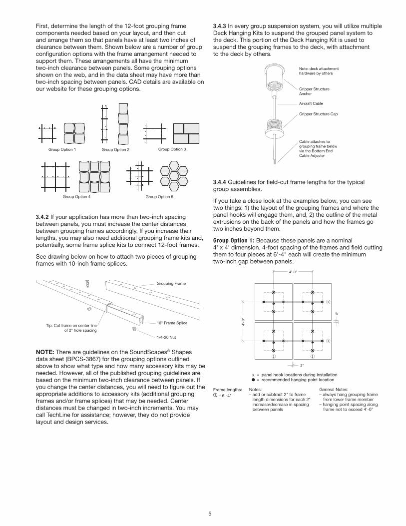
First, determine the length of the 12-foot grouping frame components needed based on your layout, and then cut and arrange them so that panels have at least two inches of clearance between them. Shown below are a number of group configuration options with the frame arrangement needed to support them. These arrangements all have the minimum two-inch clearance between panels. Some grouping options shown on the web, and in the data sheet may have more than two-inch spacing between panels. CAD details are available on our website for these grouping options.
Group Option 1 Group Option 2 Group Option 3
Group Option 4 Group Option 5
3.4.2 If your application has more than two-inch spacing between panels, you must increase the center distances between grouping frames accordingly. If you increase their lengths, you may also need additional grouping frame kits and, potentially, some frame splice kits to connect 12-foot frames.
See drawing below on how to attach two pieces of grouping frames with 10-inch frame splices.
1/4-20 x 3/4" Boltwith Washer
Grouping Frame
10" Frame Splice
1/4-20 Nut
Tip: Cut frame on center lineof 2" hole spacing
NOTE: There are guidelines on the SoundScapes® Shapes data sheet (BPCS-3867) for the grouping options outlined above to show what type and how many accessory kits may be needed. However, all of the published grouping guidelines are based on the minimum two-inch clearance between panels. If you change the center distances, you will need to figure out the appropriate additions to accessory kits (additional grouping frames and/or frame splices) that may be needed. Center distances must be changed in two-inch increments. You may call TechLine for assistance; however, they do not provide layout and design services.
3.4.3 In every group suspension system, you will utilize multiple Deck Hanging Kits to suspend the grouped panel system to the deck. This portion of the Deck Hanging Kit is used to suspend the grouping frames to the deck, with attachment to the deck by others.
Gripper StructureAnchor
Gripper Structure Cap
Note: deck attachment hardware by others
Aircraft Cable
Cable attaches togrouping frame belowvia the Bottom End Cable Adjuster
3.4.4 Guidelines for field-cut frame lengths for the typical group assemblies.
If you take a close look at the examples below, you can see two things: 1) the layout of the grouping frames and where the panel hooks will engage them, and, 2) the outline of the metal extrusions on the back of the panels and how the frames go two inches beyond them.
Group Option 1: Because these panels are a nominal 4' x 4' dimension, 4-foot spacing of the frames and field cutting them to four pieces at 6'-4" each will create the minimum two-inch gap between panels.
Notes:– add or subtract 2” to frame length dimensions for each 2” increase/ decrease in spacing between panels
Frame lengths: 6'-4"
x = panel hook locations during installation = recommended hanging point location
4'-0
"
2"
General Notes:– always hang grouping frame from lower frame member– hanging point spacing along frame not to exceed 4’-0”
4'-0"
2"
SOUNDSCAPES SHAPES 4-PANEL SQUARE LAYOUT
DESC: (4) 5440
General Notes:– always hang grouping frame from lower frame member– hanging point spacing along frame not to exceed 4'-0"
x = panel hook locations during installation ● = recommended hanging point location
Notes:– add or subtract 2" to frame
length dimensions for each 2" increase/decrease in spacing between panels
Frame lengths:1 – 6'-4"
6
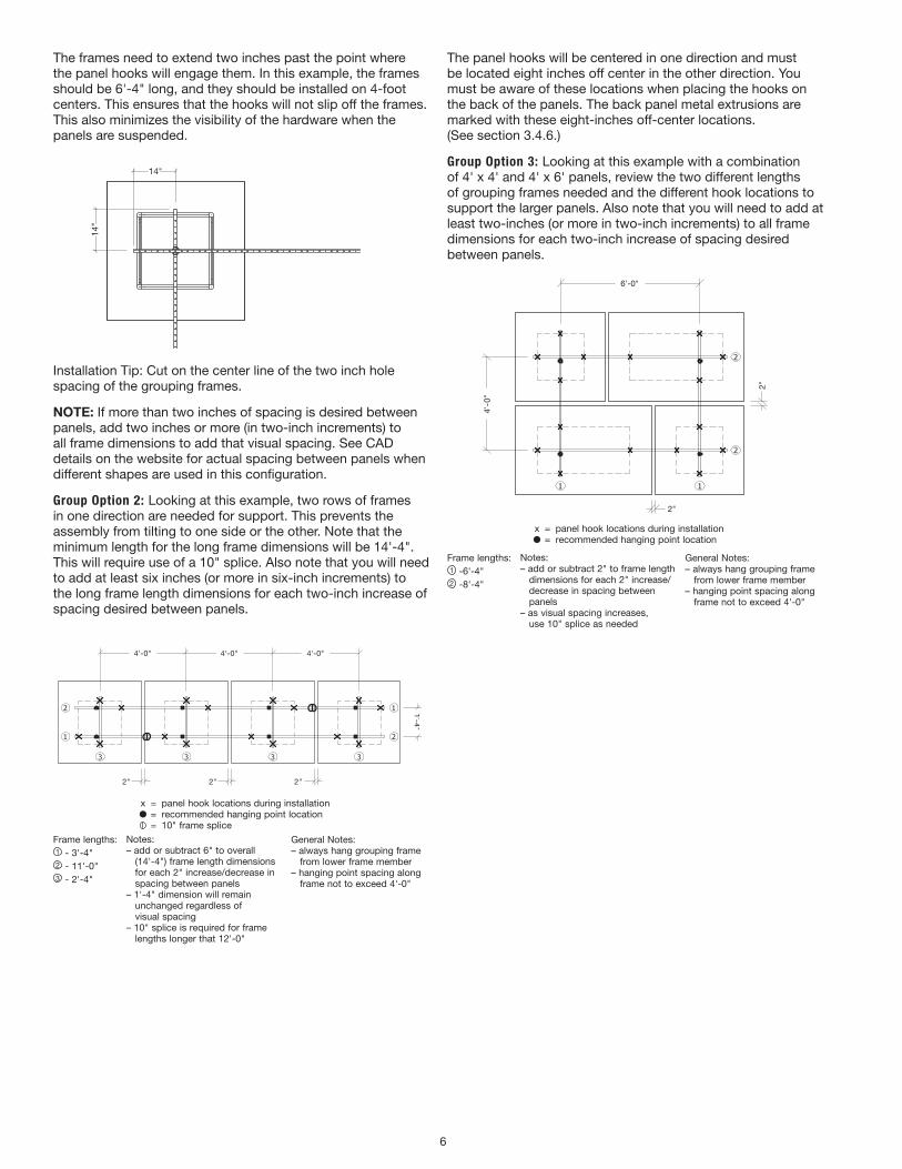
The frames need to extend two inches past the point where the panel hooks will engage them. In this example, the frames should be 6'-4" long, and they should be installed on 4-foot centers. This ensures that the hooks will not slip off the frames. This also minimizes the visibility of the hardware when the panels are suspended.
14"
14"
Installation Tip: Cut on the center line of the two inch hole spacing of the grouping frames.
NOTE: If more than two inches of spacing is desired between panels, add two inches or more (in two-inch increments) to all frame dimensions to add that visual spacing. See CAD details on the website for actual spacing between panels when different shapes are used in this configuration.
Group Option 2: Looking at this example, two rows of frames in one direction are needed for support. This prevents the assembly from tilting to one side or the other. Note that the minimum length for the long frame dimensions will be 14'-4". This will require use of a 10" splice. Also note that you will need to add at least six inches (or more in six-inch increments) to the long frame length dimensions for each two-inch increase of spacing desired between panels.
1'-4"
Notes:– add or subtract 6" to overall (14'-4") frame length dimensions for each 2" increase/ decrease in spacing between panels– 1'-4" dimension will remain unchanged regardless of visual spacing– 10" splice is required for frame lengths longer that 12'-0"
Frame lengths: 3'-4" 11'-0" 2'-4"
x = panel hook locations during installation = recommended hanging point location = 10" frame splice
2"2"
4'-0"4'-0"4'-0"
2"
General Notes:– always hang grouping frame from lower frame member– hanging point spacing along frame not to exceed 4'-0"
SOUNDSCAPES SHAPES 4-PANEL LINEAR LAYOUT
DESC: (4) 5440
General Notes:– always hang grouping frame from lower frame member– hanging point spacing along frame not to exceed 4'-0"
x = panel hook locations during installation ● = recommended hanging point location = 10" frame splice
Notes:– add or subtract 6" to overall (14'-4") frame length dimensions for each 2" increase/decrease in spacing between panels– 1'-4" dimension will remain unchanged regardless of visual spacing– 10" splice is required for frame lengths longer that 12'-0"
Frame lengths:1 - 3'-4"2 - 11'-0"3 - 2'-4"
The panel hooks will be centered in one direction and must be located eight inches off center in the other direction. You must be aware of these locations when placing the hooks on the back of the panels. The back panel metal extrusions are marked with these eight-inches off-center locations. (See section 3.4.6.)
Group Option 3: Looking at this example with a combination of 4' x 4' and 4' x 6' panels, review the two different lengths of grouping frames needed and the different hook locations to support the larger panels. Also note that you will need to add at least two-inches (or more in two-inch increments) to all frame dimensions for each two-inch increase of spacing desired between panels.
6'-0"
Notes:– add or subtract 2" to frame length dimensions for each 2" increase/ decrease in spacing between panels– as visual spacing increases, use 10" splice as needed
Frame lengths: 6'-4" 8'-4"
x = panel hook locations during installation = recommended hanging point location
4'-0
"
2"
General Notes:– always hang grouping frame from lower frame member– hanging point spacing along frame not to exceed 4'-0"
2"
SOUNDSCAPES SHAPES 4-PANEL RECTANGULAR LAYOUT
DESC: (2) 5440 (2) 5448
General Notes:– always hang grouping frame from lower frame member– hanging point spacing along frame not to exceed 4'-0"
x = panel hook locations during installation ● = recommended hanging point location
Notes:– add or subtract 2" to frame length dimensions for each 2" increase/ decrease in spacing between panels– as visual spacing increases, use 10" splice as needed
Frame lengths:1 -6'-4"2 -8'-4"
7
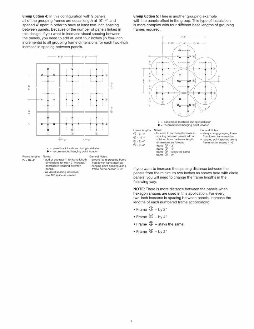
Group Option 4: In this configuration with 9 panels, all of the grouping frames are equal length at 10'-4" and spaced 4' apart in order to have at least two-inch spacing between panels. Because of the number of panels linked in this design, if you want to increase visual spacing between the panels, you need to add at least four inches (in four-inch increments) to all grouping frame dimensions for each two-inch increase in spacing between panels.
4'-0" 4'-0"
4'-0
"4'
-0"
2" 2"
2"2"
x = panel hook locations during installation = recommended hanging point location
Frame lengths: 10'-4"
Notes:– add or subtract 4" to frame length dimensions for each 2" increase/ decrease in spacing between panels– as visual spacing increases, use 10" splice as needed
General Notes:– always hang grouping frame from lower frame member– hanging point spacing along frame not to exceed 4'-0"
SOUNDSCAPES SHAPES 9-PANEL SQUARE LAYOUT
DESC: (9) 5440
General Notes:– always hang grouping frame from lower frame member– hanging point spacing along frame not to exceed 4'-0"
x = panel hook locations during installation ● = recommended hanging point location
Notes:– add or subtract 4" to frame length dimensions for each 2" increase/ decrease in spacing between panels– as visual spacing increases, use 10" splice as needed
Frame lengths:1 - 10'-4"
Group Option 5: Here is another grouping example with the panels offset in the group. This type of installation is more complex with four different base lengths of grouping frames required.
x = panel hook locations during installation = recommended hanging point location
1'-4"
Frame lengths: 6'-4" 10'-4" 2'-4" 9'-4"
2"
2'-0
"
2 1/4"
General Notes:– always hang grouping frame from lower frame member– hanging point spacing along frame not to exceed 4'-0"
Notes:– for each 2" increase/decrease in spacing between panels add or subtract from the frame length dimensions as follows: frame - 2" frame - 4" frame - stays the same frame - 2"
2'-10" 2'-10"
7'-0"
2'-0
"2'
-0"
2'-0
"
4'-0
"
SOUNDSCAPES SHAPES 7-PANEL LAYOUT
DESC: (7) 5443
General Notes:– always hang grouping frame from lower frame member– hanging point spacing along frame not to exceed 4'-0"
x = panel hook locations during installation ● = recommended hanging point location
Notes:– for each 2" increase/decrease in spacing between panels add or subtract from the frame length dimensions as follows: frame 1 – 2" frame 2 – 4" frame 3 – stays the same frame 4 – 2"
Frame lengths:1 - 6'-4"2 - 10'-4"3 - 2'-4"4- 9'-4"
If you want to increase the spacing distance between the panels from the minimum two inches as shown here with circle panels, you will need to change the frame lengths in the following way.
NOTE: There is more distance between the panels when hexagon shapes are used in this application. For every two-inch increase in spacing between panels, increase the lengths of each numbered frame accordingly:
• Frame 1 – by 2"
• Frame 2 – by 4"
• Frame 3 – stays the same
• Frame 4 – by 2"
8
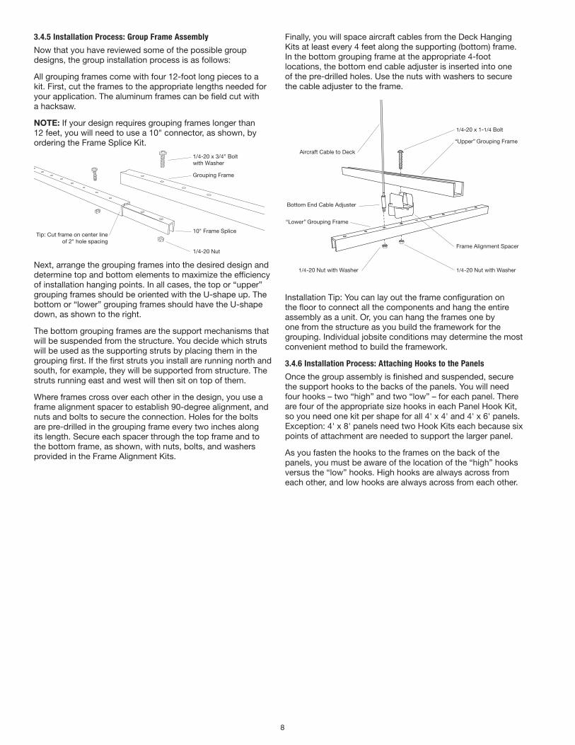
3.4.5 Installation Process: Group Frame Assembly
Now that you have reviewed some of the possible group designs, the group installation process is as follows:
All grouping frames come with four 12-foot long pieces to a kit. First, cut the frames to the appropriate lengths needed for your application. The aluminum frames can be field cut with a hacksaw.
NOTE: If your design requires grouping frames longer than 12 feet, you will need to use a 10" connector, as shown, by ordering the Frame Splice Kit.
1/4-20 x 3/4" Boltwith Washer
Grouping Frame
10" Frame Splice
1/4-20 Nut
Tip: Cut frame on center lineof 2" hole spacing
Next, arrange the grouping frames into the desired design and determine top and bottom elements to maximize the efficiency of installation hanging points. In all cases, the top or “upper” grouping frames should be oriented with the U-shape up. The bottom or “lower” grouping frames should have the U-shape down, as shown to the right.
The bottom grouping frames are the support mechanisms that will be suspended from the structure. You decide which struts will be used as the supporting struts by placing them in the grouping first. If the first struts you install are running north and south, for example, they will be supported from structure. The struts running east and west will then sit on top of them.
Where frames cross over each other in the design, you use a frame alignment spacer to establish 90-degree alignment, and nuts and bolts to secure the connection. Holes for the bolts are pre-drilled in the grouping frame every two inches along its length. Secure each spacer through the top frame and to the bottom frame, as shown, with nuts, bolts, and washers provided in the Frame Alignment Kits.
Finally, you will space aircraft cables from the Deck Hanging Kits at least every 4 feet along the supporting (bottom) frame. In the bottom grouping frame at the appropriate 4-foot locations, the bottom end cable adjuster is inserted into one of the pre-drilled holes. Use the nuts with washers to secure the cable adjuster to the frame.
Bottom End Cable Adjuster
1/4-20 Nut with Washer
Aircraft Cable to Deck
1/4-20 x 1-1/4 Bolt
“Lower” Grouping Frame
“Upper” Grouping Frame
Frame Alignment Spacer
1/4-20 Nut with Washer
Installation Tip: You can lay out the frame configuration on the floor to connect all the components and hang the entire assembly as a unit. Or, you can hang the frames one by one from the structure as you build the framework for the grouping. Individual jobsite conditions may determine the most convenient method to build the framework.
3.4.6 Installation Process: Attaching Hooks to the Panels
Once the group assembly is finished and suspended, secure the support hooks to the backs of the panels. You will need four hooks – two “high” and two “low” – for each panel. There are four of the appropriate size hooks in each Panel Hook Kit, so you need one kit per shape for all 4' x 4' and 4' x 6' panels. Exception: 4' x 8' panels need two Hook Kits each because six points of attachment are needed to support the larger panel.
As you fasten the hooks to the frames on the back of the panels, you must be aware of the location of the “high” hooks versus the “low” hooks. High hooks are always across from each other, and low hooks are always across from each other.
9
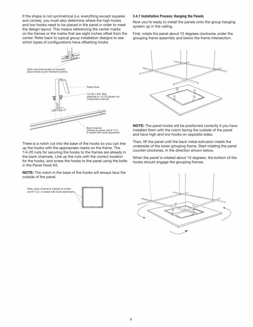
If the shape is not symmetrical (i.e. everything except squares and circles), you must also determine where the high hooks and low hooks need to be placed in the panel in order to meet the design layout. This means referencing the center marks on the frames or the marks that are eight inches offset from the center. Refer back to typical group installation designs to see which types of configurations have offsetting hooks.
Panel Hook
Back channelmarked at center and 8" O.C. to assist with hook placement
1/4-20 x 3/8" Boltattaches to 1/4-20 square nut inside back channel
Note: back channel is marked at centerand 8" O.C. to assist with hook placement
Note: use hook locator to correctlyplace hooks at pre-marked locations
There is a notch cut into the base of the hooks so you can line up the hooks with the appropriate marks on the frame. The 1/4-20 nuts for securing the hooks to the frames are already in the back channels. Line up the nuts with the correct location for the hooks, and screw the hooks to the panel using the bolts in the Panel Hook Kit.
NOTE: The notch in the base of the hooks will always face the outside of the panel.
Panel Hook
Back channelmarked at center and 8" O.C. to assist with hook placement
1/4-20 x 3/8" Boltattaches to 1/4-20 square nut inside back channel
Note: back channel is marked at centerand 8" O.C. to assist with hook placement
Note: use hook locator to correctlyplace hooks at pre-marked locations
3.4.7 Installation Process: Hanging the Panels
Now you’re ready to install the panels onto the group hanging system up in the ceiling.
First, rotate the panel about 10 degrees clockwise under the grouping frame assembly and below the frame intersection.
hanging the panelstep one: rotated about 10 degrees counterclockwise, orient the panel below the frame intersection
NOTE: The panel hooks will be positioned correctly if you have installed them with the notch facing the outside of the panel and have high and low hooks on opposite sides.
Then, lift the panel until the back metal extrusion meets the underside of the lower grouping frame. Start rotating the panel counter-clockwise, in the direction shown below.
When the panel is rotated about 10 degrees, the bottom of the hooks should engage the grouping frames.
hanging the panelstep two: lift the panel until the back channel meets the underside of the lower U235 strut

10
Let the panel drop carefully into place with the four panel hooks engaging the upper and lower frames.
hanging the panelstep three: rotate the panel about 10 degrees clockwiseuntil the strap hook hits the U235 strut
Repeat as necessary for the number of panels you have in your group configuration.
hanging the panelstep four: let the panel drop into place, the strap hook engaging the upper & lower U235 strut
Adjust the hanging height of group system as needed.
ImpORTANT SAfETy ANd QuAlITy NOTE: Do not allow any portion of aircraft cable to drop below the panels while adjusting final panel height. To do so could cause injury to the installer or damage to the edge of a panel.
hanging the panelstep �ve: repeat as necessary (x3 as shown)
3.5 Multi-plane Hanging Kits
Refer to Section 3.4.6 for installation of hooks on the back of panels. The only difference with these hooks is that they lower the panels a different distance (1", 2", or 3") from the grouping frame.
3.6 Installing Shapes Below an Existing Suspended Ceiling
Suspension cables used with SoundScapes® Shapes suspended from the deck (either individually or as a group) should not impose any lateral force on an existing suspended ceiling.
1/4-20NC Threaded Rod not included
Gripper Structure Anchor
Escutcheon
1. The structure gripper anchor must be mounted to a
support at, or above, the existing ceiling.
2. Use 1/4–20 threaded rod attached to structure to secure the structure gripper anchor at the correct height.
3. Use diagonal bracing to structure to provide support.
4. Use the optional escutcheon accessory kit to conceal the structure gripper anchor when installed above the ceiling level. Escutcheon Kit #7006
• (2) Collars with set screws
• (2) Escutcheons (2")
3.7 Panel Penetrations
The panels can be field cut for penetrations such as lighting or sprinklers as long as the fixtures are independently supported and not supported in any way by the panel suspension system.
11
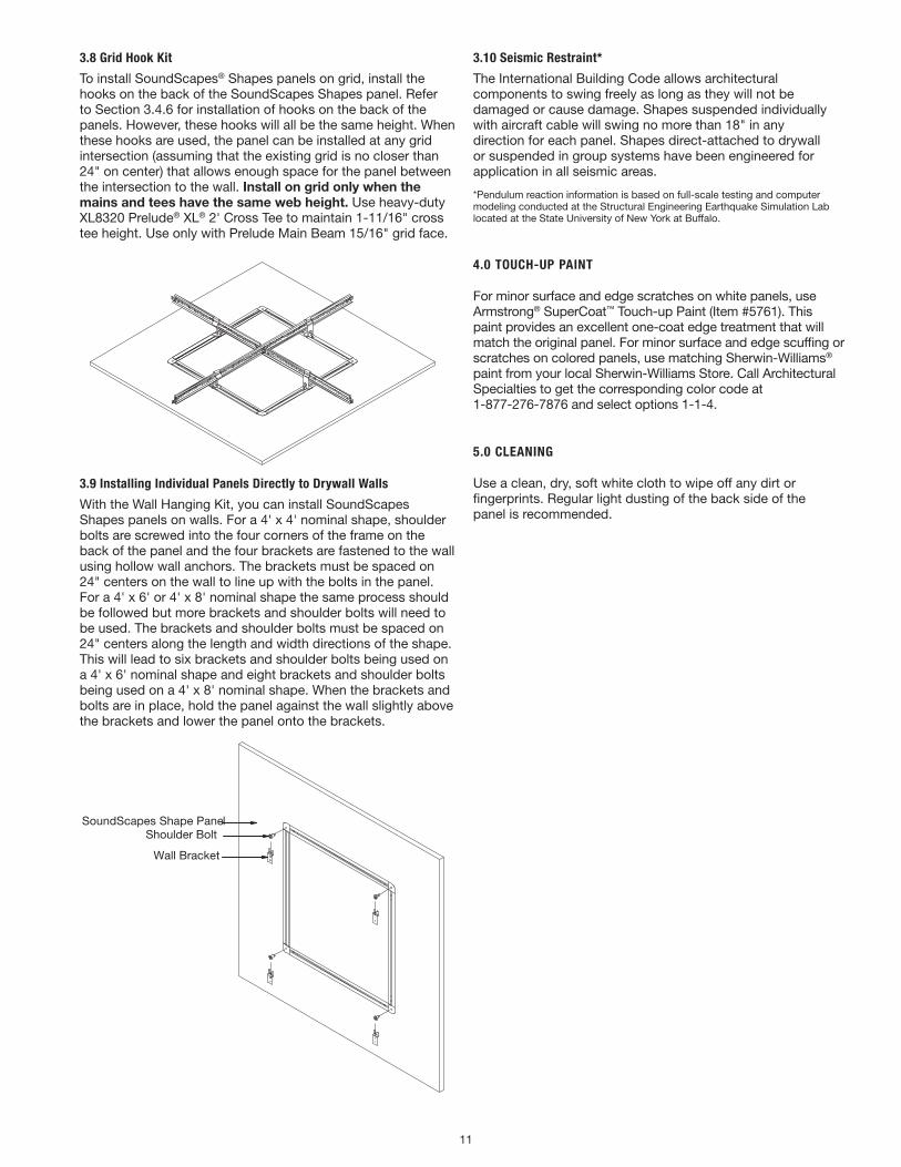
3.8 Grid Hook Kit
To install SoundScapes® Shapes panels on grid, install the hooks on the back of the SoundScapes Shapes panel. Refer to Section 3.4.6 for installation of hooks on the back of the panels. However, these hooks will all be the same height. When these hooks are used, the panel can be installed at any grid intersection (assuming that the existing grid is no closer than 24" on center) that allows enough space for the panel between the intersection to the wall. Install on grid only when the mains and tees have the same web height. Use heavy-duty XL8320 Prelude® XL® 2' Cross Tee to maintain 1-11/16" cross tee height. Use only with Prelude Main Beam 15/16" grid face.
3.9 Installing Individual Panels Directly to Drywall Walls
With the Wall Hanging Kit, you can install SoundScapes Shapes panels on walls. For a 4' x 4' nominal shape, shoulder bolts are screwed into the four corners of the frame on the back of the panel and the four brackets are fastened to the wall using hollow wall anchors. The brackets must be spaced on 24" centers on the wall to line up with the bolts in the panel. For a 4' x 6' or 4' x 8' nominal shape the same process should be followed but more brackets and shoulder bolts will need to be used. The brackets and shoulder bolts must be spaced on 24" centers along the length and width directions of the shape. This will lead to six brackets and shoulder bolts being used on a 4' x 6' nominal shape and eight brackets and shoulder bolts being used on a 4' x 8' nominal shape. When the brackets and bolts are in place, hold the panel against the wall slightly above the brackets and lower the panel onto the brackets.
Wall Bracket
Shoulder BoltSoundScapes Shape Panel
(1) BP5588 Wall Mount Kit:(4) BP539 Wall Brackets(4) BP5347 Shoulder Screws
3.10 Seismic Restraint*
The International Building Code allows architectural components to swing freely as long as they will not be damaged or cause damage. Shapes suspended individually with aircraft cable will swing no more than 18" in any direction for each panel. Shapes direct-attached to drywall or suspended in group systems have been engineered for application in all seismic areas.
*Pendulum reaction information is based on full-scale testing and computer modeling conducted at the Structural Engineering Earthquake Simulation Lab located at the State University of New York at Buffalo.
4.0 TOUCH-UP PAINT
For minor surface and edge scratches on white panels, use Armstrong® SuperCoat™ Touch-up Paint (Item #5761). This paint provides an excellent one-coat edge treatment that will match the original panel. For minor surface and edge scuffing or scratches on colored panels, use matching Sherwin-Williams® paint from your local Sherwin-Williams Store. Call Architectural Specialties to get the corresponding color code at 1-877-276-7876 and select options 1-1-4.
5.0 CLEANING
Use a clean, dry, soft white cloth to wipe off any dirt or fingerprints. Regular light dusting of the back side of the panel is recommended.
7.00 (+/-0.125)
.38
1/16" 7x7 304 Stainless Steel Cable
1/4-20 Steel Stud - 1" Long#87 Zinc Die Cast Terminal (both ends)
MORE INFORMATION
ITEM # KIT CONTENTS
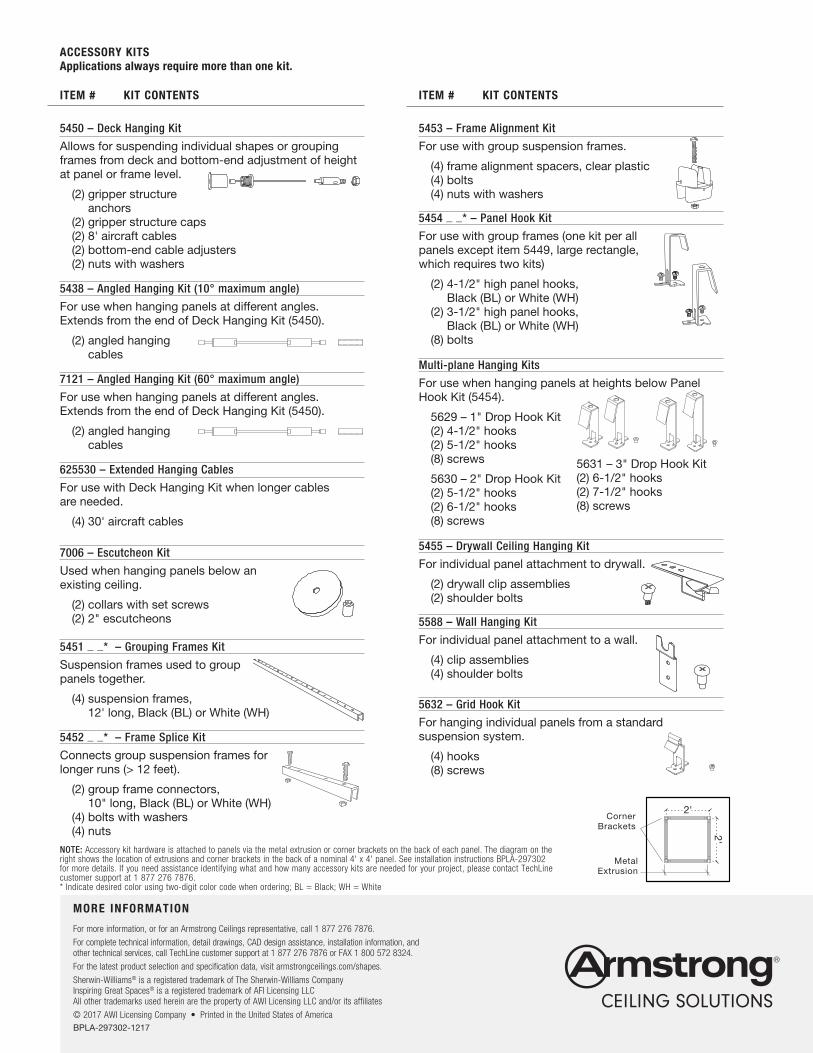
5450 – Deck Hanging Kit
Allows for suspending individual shapes or grouping frames from deck and bottom-end adjustment of height at panel or frame level.
(2) gripper structure anchors
(2) gripper structure caps (2) 8' aircraft cables (2) bottom-end cable adjusters (2) nuts with washers
5438 – Angled Hanging Kit (10° maximum angle)
For use when hanging panels at different angles. Extends from the end of Deck Hanging Kit (5450).
(2) angled hanging cables
7121 – Angled Hanging Kit (60° maximum angle)
For use when hanging panels at different angles. Extends from the end of Deck Hanging Kit (5450).
(2) angled hanging cables
625530 – Extended Hanging Cables
For use with Deck Hanging Kit when longer cables are needed.
(4) 30' aircraft cables
7006 – Escutcheon Kit
Used when hanging panels below an existing ceiling.
(2) collars with set screws (2) 2" escutcheons
5451 _ _* – Grouping Frames Kit
Suspension frames used to group panels together.
(4) suspension frames, 12' long, Black (BL) or White (WH)
5452 _ _* – Frame Splice Kit
Connects group suspension frames for longer runs (> 12 feet).
(2) group frame connectors, 10" long, Black (BL) or White (WH)
(4) bolts with washers (4) nuts
ACCESSORY KITS Applications always require more than one kit.
NOTE: Accessory kit hardware is attached to panels via the metal extrusion or corner brackets on the back of each panel. The diagram on the right shows the location of extrusions and corner brackets in the back of a nominal 4' x 4' panel. See installation instructions BPLA-297302 for more details. If you need assistance identifying what and how many accessory kits are needed for your project, please contact TechLine customer support at 1 877 276 7876.* Indicate desired color using two-digit color code when ordering; BL = Black; WH = White
ITEM # KIT CONTENTS
5453 – Frame Alignment Kit
For use with group suspension frames.
(4) frame alignment spacers, clear plastic (4) bolts (4) nuts with washers
5454 _ _* – Panel Hook Kit
For use with group frames (one kit per all panels except item 5449, large rectangle, which requires two kits)
(2) 4-1/2" high panel hooks, Black (BL) or White (WH)
(2) 3-1/2" high panel hooks, Black (BL) or White (WH)
(8) bolts
Multi-plane Hanging Kits
For use when hanging panels at heights below Panel Hook Kit (5454).
5629 – 1" Drop Hook Kit (2) 4-1/2" hooks (2) 5-1/2" hooks (8) screws
5630 – 2" Drop Hook Kit (2) 5-1/2" hooks (2) 6-1/2" hooks (8) screws
5455 – Drywall Ceiling Hanging Kit
For individual panel attachment to drywall.
(2) drywall clip assemblies (2) shoulder bolts
5588 – Wall Hanging Kit
For individual panel attachment to a wall.
(4) clip assemblies (4) shoulder bolts
5632 – Grid Hook Kit
For hanging individual panels from a standard suspension system.
(4) hooks (8) screws
Corner Brackets
2'
2'
4'
2'
6'
2'
Metal Extrusion
7.00 (+/-0.125)
.38
1/16" 7x7 304 Stainless Steel Cable
1/4-20 Steel Stud - 1" Long#87 Zinc Die Cast Terminal (both ends)
5631 – 3" Drop Hook Kit(2) 6-1/2" hooks(2) 7-1/2" hooks(8) screws
BPLA-297302-1217
For more information, or for an Armstrong Ceilings representative, call 1 877 276 7876.
For complete technical information, detail drawings, CAD design assistance, installation information, and other technical services, call TechLine customer support at 1 877 276 7876 or FAX 1 800 572 8324.
For the latest product selection and specification data, visit armstrongceilings.com/shapes.
Sherwin-Williams® is a registered trademark of The Sherwin-Williams Company Inspiring Great Spaces® is a registered trademark of AFI Licensing LLC All other trademarks used herein are the property of AWI Licensing LLC and/or its affiliates
© 2017 AWI Licensing Company • Printed in the United States of America