Embed Size (px)
Citation preview

1 107030400-TS0001-R00
SPALLATION NEUTRON SOURCE PERFORMANCE SPECIFICATION
60 Hz BANDWIDTH LIMITING NEUTRON CHOPPER SYSTEM March 5, 2003
1. GENERAL DESCRIPTION AND REQUIREMENTS 1.1. Introduction 1.1.1. A bandwidth limiting neutron chopper is a rotating mass; i.e., rotor assembly, inserted in
the flight path of a neutron beam. The rotor assembly includes a fixed single angular aperture neutron blocking disk that controls the bandwidth of the neutron pulses enroute to the sample environment.
1.1.2. The pulsed-neutron burst rate, the particle-accelerator timing system, the motor control
system electronics, and the motor operating speed are intimately related. The rotor blade-passage-time and angular positioning of the disk with respect to the neutron timing are essential to the effective and efficient operation of the bandwidth limiting chopper. Accurate and repeatable angular positioning of the rotating chopper is critical to its successful operation.
1.2. System Requirements 1.2.1. The reliability of the entire neutron-chopper system including the rotor assembly,
bearings, drive motor, and drive motor control system shall be such that it can operate continuously at rated speed for at least 24 months between maintenance periods. The manufacturer/supplier shall provide a listing of components subject to wear and/or performance degradation along with a mean-time-between-failures for the component.
1.2.2. The following paragraphs describe the performance specifications. A block diagram of
the system is as shown by Figure 1.2-1.

2 107030400-TS0001-R00
Control System
local monitor computer
Misc. interlocks
Motor speed control
shafts bearings rotors
water cooling if req'd
vacuum port
vacuum vessel
AC power
neutron path
Figure 1.2-1. Block diagram of the bandwidth limiting neutron chopper system 1.2.3. Figure 1.2-1 indicates that the rotor assembly spins in a housing, and is controlled by the
drive motor speed control unit. Appropriate system level and subsystem level interlocks are required. The reference, control, and interlock signals are shown to represent the types of signals that are expected.
2. DRIVE SHAFT AND ROTOR
For purposes of clarity, the drive shaft is defined in this document as the cylindrical rod assembly which supports and drives the rotating mass and which is supported by bearings. The rotor assembly is defined as the total rotating assembly of the drive shaft, rotating mass, and any other associated rotating components. 2.1. Rotor Speed The rotor shall be able to operate at any speed from 360 to 3,600 rpm (60 Hz). 2.2. Orientation The rotor assembly shall be mounted and operated with its rotation axis oriented within ±5° of a horizontal plane.

3 107030400-TS0001-R00
2.3. Disk Mounting Position The shaft shall be designed to attach to the disk. The disk will be assembled to the shaft with the mass placed in an over-hung configuration at one end of the shaft. 2.4. Disk Information 2.4.1. The disk assembly consists of a neutron blocking disk and its connection to the shaft.
The standard disk has representative dimensions as shown in Figure 2.4-1. Special applications may require variations from the standard disk geometry. Dimensions are in inches [mm].
Figure 2.4-1. Bandwidth limiting chopper disk geometry 2.4.2. The disk which carries the TBD neutron blocking material shall be made of TBD
material. The nature and the extent of the neutron blocking material will be determined by the neutron stopping requirement for the particular chopper application considered. The determination will be made by the vendor and will be reviewed by SNS. The instrument specific requirements are as given by Table 2.4-1.

4 107030400-TS0001-R00
Table 2.4-1. Bandwidth Limiting Chopper Disk Requirements Chopper ID Configura-
tion Beam Width (cm)
Beam Height (cm)
Axis to beam center
(cm)
Open angle (deg)
Transmis- sion at 1 Å1
Notes: 1. For any mm2 of the coated portion of the disk surface. SNS will verify performance with
neutron radiography. 2.4.3. The disk open angle error as machined shall be within ±0.1°. 2.4.4. The disk radial features shall be within ±0.020 inch (0.5 mm). 2.4.5. The disk assembly must be capable of straightforward change-out in order to allow
utilization of different disk assemblies in a common drive shaft and housing configuration on a given chopper assembly.
2.5. Direction of Rotation 2.5.1. The rotor assembly shall be capable of spinning in either direction.

5 107030400-TS0001-R00
2.5.2. The important criterion is that the timing of the rotor be well defined and controlled in phase relative to a 60 Hz Master Pulse signal from the accelerator and/or other choppers. Operating bandwidth limiting chopper systems may have different directions of rotation.
2.6. Rotor Angular Alignment The rotor shall be designed, made, and assembled such that a sensor signal, to be known as Top Dead Center (TDC), is available to indicate the disk aperture centerline position relative to the neutron beam center. This sensor signal shall have a positional; i.e., location on the disk, accuracy of better than ±1 deg. For a given disk, a rotational positional repeatability of better than ±0.1 deg when operated within the specified frequency range. For external use, this signal or a copy of it shall be made available at a BNC cable connector mounted on the front of the equipment control unit. The signal, of a nominal duration between 10 and 100 µs, shall be capable of driving a TTL 50 ohm load. 2.7. Rotating Mass Dynamic Balancing In order to control vibration and reduce bearing loading to unbalance, the rotating mass will be dynamically balanced to an ISO 1940/1 and ANSI 52.19 G1.0 balancing grade. 2.8. Environment The rotor and mechanical bearings shall operate in a vacuum environment at the level as specified in Section 6.3.2. Bearing heating shall not be detrimental to bearing operating lifetime.
3. BEARINGS 3.1. Bearing Type 3.1.1. The bearing system shall employ conventional ball bearings, having an all steel or a
ceramic hybrid configuration, or magnetic bearings. 3.1.2. Grease migration characteristics and control are important factors to be considered in
bearing design and selection. No hydrocarbons are to be present in the evacuated region of the housing as they lead to adverse neutron scattering conditions.

6 107030400-TS0001-R00
3.2. Load Weight 3.2.1. The bearing system shall be capable of supporting the complete rotor with a sufficient
margin to accommodate force disturbances up to at least 150% of nominal. 3.2.2. The final weight and dimensions of the rotor are to be determined by the final integrated
design of the disks and the drive shaft and its attachments. 3.3. Reliability 3.3.1. Interlocks and other necessary safety precautions shall be incorporated. (Refer to Section
4.5.3.) 3.3.2. The reliability of the bearings shall be in keeping with the system requirement for a
minimum 24-month continuous operation of the entire chopper system. 3.4. Change-Out Requirement The rotor assembly, bearings, and housing shall be designed and implemented to facilitate the removal and replacement of a disk in keeping with a 4-hour bench-time change-out requirement. 3.5. Operating Speed The bearing system shall be capable of operation up to and including 3,600 rpm (60 Hz).
4. ELECTRIC DRIVE SYSTEM 4.1. Operational Speed 4.1.1. The chopper will operate continuously at rotational speeds up to 60 Hz, with the
capability of subharmonic operation; i.e., 30, 20, 15, 12, 10, 6, ... Hz, when following a 60 Hz Master Pulse. Refer to Section 4.4.1.
4.1.2. The drive motor should be able to turn in both directions, User selectable.

7 107030400-TS0001-R00
4.2. Master Pulse The chopper drive system controls the angular position of the rotating neutron blocking disks relative to an externally supplied nominally 60 Hz Master Pulse. The Master Pulse is rephased to follow the long-term variation of the line frequency; i.e., 60 ±0.2 Hz with a maximum slew rate of the frequency limited to 0.5 Hz/500 s. In order to verify the performance specifications listed below, the Master Pulse shall be modulated such that the output frequency varies as a sawtooth waveform shown by Figure 4.2-1.
Frequency
Time
60.2
59.8
800 sec
Figure 4.2-1. Master Pulse test verification waveform The variation rate of the Master Pulse may change as more experience is gained. In the event of Master Pulse lost, the drive should continue to operate at the set speed. The Master Pulse input should be a BNC connector located in close proximity to the TDC output connector. The Master Pulse input signal will be capable of driving a single TTL load. The duration of the pulse shall nominally be 10 to 180 µs. 4.3. Control For a given chopper, the drive system's controls will provide the function of Master Pulse following. The motor will have a separate controller, with a Master Pulse input. Pulse following and verification functions are included in the control system. When operating at subsynchronous speeds (<60 Hz), a second chopper must be able to be synchronized with a primary chopper so that the disk windows can be aligned. Therefore in addition to following the Master Pulse input reference, the controller must also be able to sync on a TDC signal from another chopper to ensure window alignment when choppers are in a back to back configuration.

8 107030400-TS0001-R00
4.4. Performance Requirements
4.4.1. Continuous duty at 60 Hz and subharmonics; i.e., 30, 20, 15, 12, 10, 6 Hz when provided with a 60 Hz Master Pulse.
4.4.2. Allowable drift; i.e., timing error, about the Master Pulse set point during operation is
±10 µs at 60 Hz (±0.22° @ 60 Hz). All lower speeds to be within ±0.22°. The timing error vs. speed requirement is as given by Table 4.4.2-1.
Table 4.4.2-1. Timing Requirements
Nominal Speed Acceptance Window
(Full Width) Acceptance
Rate Veto Rate
(rpm) (Hz) (µs) (°) 3600 60 20 0.43 99% 1% 1800 30 40 0.43 99% 1% 1200 20 60 0.43 99% 1% 900 15 80 0.43 99% 1% 720 12 100 0.43 99% 1% 600 10 120 0.43 99% 1% 360 6 200 0.43 99% 1%
4.4.3. Power output and operational speeds:
• TBD (by drive system supplier/manufacturer) kW at 60 Hz • Operational speeds as 1/10, 1/6, 1/5, 1/4, 1/3, 1/2, and 1 times the supplied 60 Hz
Master Pulse; i.e., nominally 6, 10, 12, 15, 20, 30, 60 Hz 4.4.4. A phase set point capability to retard or advance the blade position relative to the Master
Pulse with a resolution of 1 µs over the entire 360° angular space for all speeds. 4.4.5. Computer readout of phase error; i.e., difference between actual position and demand
position, at a rate of at least twice per second. The controller/computer shall maintain a local buffer of the last 30 s of readings. If raw data is not available remotely, then a
9 107030400-TS0001-R00
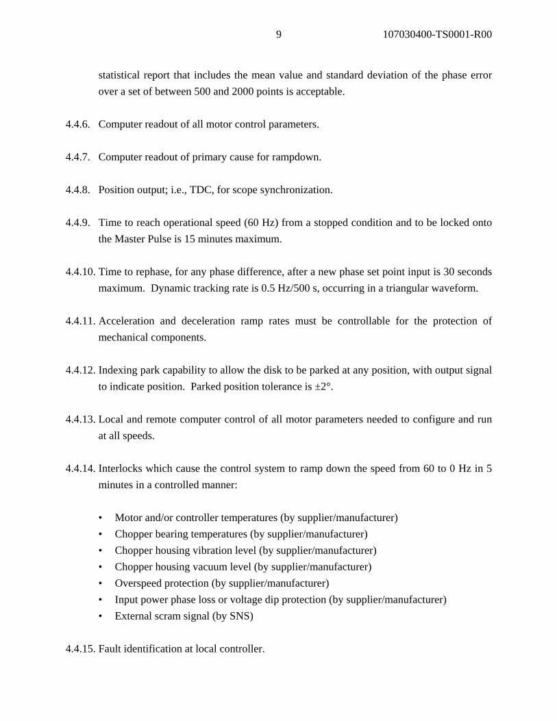
statistical report that includes the mean value and standard deviation of the phase error over a set of between 500 and 2000 points is acceptable.
4.4.6. Computer readout of all motor control parameters. 4.4.7. Computer readout of primary cause for rampdown. 4.4.8. Position output; i.e., TDC, for scope synchronization. 4.4.9. Time to reach operational speed (60 Hz) from a stopped condition and to be locked onto
the Master Pulse is 15 minutes maximum. 4.4.10. Time to rephase, for any phase difference, after a new phase set point input is 30 seconds
maximum. Dynamic tracking rate is 0.5 Hz/500 s, occurring in a triangular waveform. 4.4.11. Acceleration and deceleration ramp rates must be controllable for the protection of
mechanical components. 4.4.12. Indexing park capability to allow the disk to be parked at any position, with output signal
to indicate position. Parked position tolerance is ±2°. 4.4.13. Local and remote computer control of all motor parameters needed to configure and run
at all speeds. 4.4.14. Interlocks which cause the control system to ramp down the speed from 60 to 0 Hz in 5
minutes in a controlled manner:
• Motor and/or controller temperatures (by supplier/manufacturer) • Chopper bearing temperatures (by supplier/manufacturer) • Chopper housing vibration level (by supplier/manufacturer) • Chopper housing vacuum level (by supplier/manufacturer) • Overspeed protection (by supplier/manufacturer) • Input power phase loss or voltage dip protection (by supplier/manufacturer) • External scram signal (by SNS)
4.4.15. Fault identification at local controller.

10 107030400-TS0001-R00
4.4.16. The drive system shall incorporate an enable interlock feature. The feature will require
that all interlocks are made in order to enable operation. In the event of an interlock drop-out, the interlock must be reset to enable return to operation. A keyed enable override feature shall be provided for diagnostic/troubleshooting purposes.
4.4.17. Reliability and Lifetime The drive system is to operate reliably over a 24 month minimum time between
maintenance. Drive system design must consider and implement measures to achieve high reliability and satisfactory lifetime. Radiation tolerance of materials and components is an important consideration.
4.5 Drive System Configuration and Capabilities 4.5.1. Major Components
• Motor • Power supply and controller • Diagnostics and instrumentation • Interconnecting cabling
4.5.2. Motor
• The motor shaft/rotor details will be determined by the design of the motor to
chopper interfaces. • The motor shaft shall incorporate the installation of a radiation hard angular position
transducer by the vendor. The transducer shall be in addition to the motor radiation hard resolver. The transducer and resolver position on the shaft is at the driven end. The transducers' radiation tolerances are important considerations.
• Motor compactness is an important consideration.

11 107030400-TS0001-R00
• Elastomeric seal selection should include radiation tolerance/lifetime considerations (Section 9.5). Welded or brazed connections in the cooling water circuit (if employed) are recommended. Metallic compression seals are recommended.
4.5.3. Power Supply and Controller
• Components include motor power supply, controller, necessary interfaces, and cabling.
• The system shall operate off site power. Three options are available:
* 480 V, 3φ, 60 Hz * 208 V, 3φ, 60 Hz * 120 V, 1φ, 60 Hz
• Resistive or regenerative braking may be employed. If regenerative braking is used,
the manufacturer should provide suitable input mains filtering as to eliminate the impact of noise reflected back out on the input mains.
• The drive controller is connected to and receives control commands and signals from
the Neutron Beam Chopper Control System. • Controller operating modes The drive shall be controllable in two modes:
* Local control * Remote control via EIA RS-232/RS-485
• Local controller functions:
* Rotor rotation direction * Rotor angular position (phase) * Rotor operation in phased locked mode * Rotor speed control * Normal braking
12 107030400-TS0001-R00
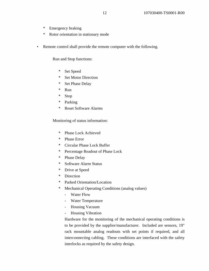
* Emergency braking * Rotor orientation in stationary mode
• Remote control shall provide the remote computer with the following.
Run and Stop functions: * Set Speed
* Set Motor Direction * Set Phase Delay * Run * Stop * Parking * Reset Software Alarms
Monitoring of status information: * Phase Lock Achieved * Phase Error * Circular Phase Lock Buffer * Percentage Readout of Phase Lock * Phase Delay * Software Alarm Status * Drive at Speed * Direction * Parked Orientation/Location * Mechanical Operating Conditions (analog values) - Water Flow - Water Temperature - Housing Vacuum - Housing Vibration
Hardware for the monitoring of the mechanical operating conditions is to be provided by the supplier/manufacturer. Included are sensors, 19" rack mountable analog readouts with set points if required, and all interconnecting cabling. These conditions are interfaced with the safety interlocks as required by the safety design.

13 107030400-TS0001-R00
Design details of Analog to Serial conversion hardware to be provided by SNS for the above mentioned analog values.
The RS-232/RS-485 port shall be configured for default operation of two stop bits, 8
data bits, and no parity bit. Transmission of packets shall be at 9,600 baud with the capability of transmission of higher rates of 19,200, 38,400, 57,600, and 115,200 baud. Data shall be sent in the Little Endian Format..
Any other control function that the drive manufacturer finds necessary to the
operation of the drive may be added to the communication port. • Controller exchange/changeout: The chopper and the controller shall be of interchangeable natures and their
exchange/changeout shall be such as to minimize retuning of the system.
4.5.4. Software API Software library for implementing remote control shall be Windows 2000/XP compliant
and work with popular Windows development systems like MS Visual C++, MS Visual Basic, and National Instruments Measurement Studio programming environments. A generic Send and Receive String function is also desirable so future or custom commands can be implemented with this same API Library. Specific communications hardware (type: RS-485, USB, etc. and manufacturer/model number) for development and verification testing is TBD).
4.5.5. Diagnostics and Instrumentation
• Rotor position transducer • Protection thermal sensor(s) •. Vacuum sensor • Vibration Sensor(s)

14 107030400-TS0001-R00
• Other possible sensors TBD by drive system manufacturer/supplier.
4.5.6. Component Hardware Mounting All control and diagnostic component hardware shall be installed on panels suitable for
19" rack mounting. The manufacturer/supplier, as an option, may offer all hardware mounted in a suitably sized 19" rack.
4.5.7. Interconnecting Cabling
• Power and signal cables between the drive motor and its controller shall be up to 200 ft (61 m) long. The actual lengths will be specified at the time of order and will be determined by the specific requirements for the intended instrument application.
• All cables to be terminated with commercially available connectors having industrial
quality strain reliefs. • All cables to be labeled at both ends with descriptors that correspond to those labeled
on the components to be connected. 4.5.8. Conformation to Electrical Standards and Codes
The drive system shall be designed and manufactured to conform to electrical standards and codes as defined by SNS Document No. 102030102ES0012-R0/SNS Standards for Design and Construction of the Target Facility. SNS has a waiver procedure for equipment that does not have UL approval.
4.6. Electromagnetic Compatibility When integrating the drive system into a neutron chopper installation, the most critical part of the system is the rotor assembly angular position feedback information generated by the position transducer(s) and associated circuitry. These signals are highly significant to the operation and performance of the drive system and precautions should be taken to avoid any interference from external sources.

15 107030400-TS0001-R00
4.7. Magnetic Compatibility Certain applications will involve neutron beams that are affected by nearby magnetic fields and magnetic materials. The design shall eliminate fringe magnetic fields and the presence of magnetic materials in the beam region. The SNS will review the predicted magnetic environment.
5. INSTALLATION The chopper will be installed in the SNS beamlines as determined by the design of the specific instruments. Installation requirements are influenced by available space; relationship to other beam line components, such as neutron guides; changeout features for service, etc. 5.1. Chopper Configuration The configuration of the chopper assembly is as shown by Figure 5.1-1. Representative key external dimensions are as indicated.
Mounting plate locations
7.8 inch (200 mm)
Figure 5.1-1. Chopper configuration

16 107030400-TS0001-R00
5.1.1. Disk Housing Thickness
The overall thickness shall be minimized to permit close spacing of the neutron guide sections upstream and downstream of the chopper. The maximum allowable gap between neutron guide ends is 2 inch (51 mm) over a 5.1 inch (130 mm) horizontal by 5.9 inch (150 mm) vertical area centered at the neutron beam line. The chopper shall be capable of sliding in and out in all installed orientations (Section 5.2).
5.1.2. Disk Housing Free Face
The free face side of the housing, opposite the drive motor, shall be free of projections in order to allow for close placement with adjacent chopper assemblies in the beamline.
5.1.3. Drive Package
The drive package shall be configured to achieve the most compact axial and radial geometry corresponding to the drive type employed and its associated shaft suspension components.
5.1.4. External Geometry
The chopper external geometry shall be compact in nature and uncluttered with features that would complicate installation and the installation of radiation shielding around the chopper.
5.1.5. Mounting Provisions The chopper shall utilize mounting plates bolted to the support legs. The approximate location of the mounting plates is illustrated in Figure 5.1-1. The chopper housing design should accommodate these provisions.
5.2. Installed Orientations There will be two possible installed orientations. Specific orientations will be specified on an instrument as-used basis.

17 107030400-TS0001-R00
5.2.1. Supported-from-the-Top
The primary installed orientation is with the chopper supported from the top as shown by Fig. 5.2-1.
Figure 5.2-1. Chopper supported from the top 5.2.2. Supported-from-the-Side
A secondary installed orientation is with the chopper as supported from the side as shown by Figure 5.2-2.

18 107030400-TS0001-R00
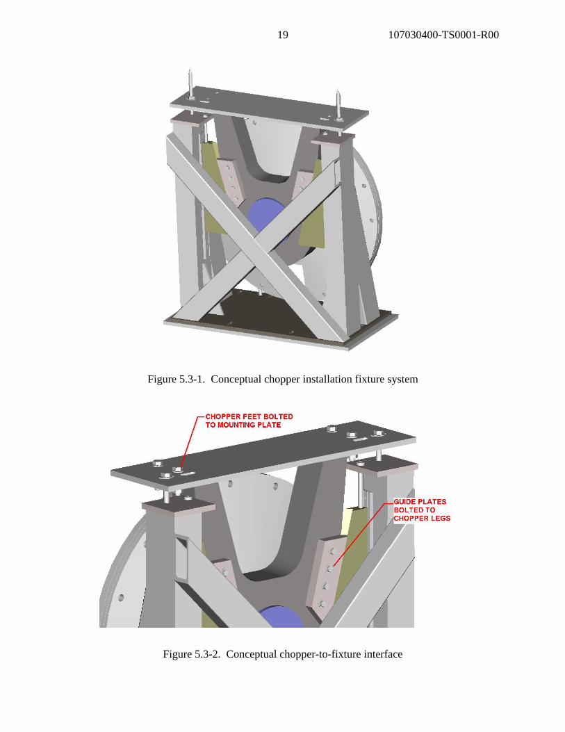
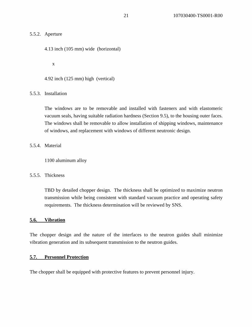
Figure 5.2-2. Chopper supported from the side 5.3. Installation Fixtures Installation fixtures will be utilized to control chopper motion during installation and to position (align) the chopper relative to the beamline. A conceptual fixture system is as shown by Figure 5.3-1. The installation fixtures are the responsibility of the SNS and will be installed on the choppers at the time of chopper installation. The chopper-to-fixture interfaces are TBD by detailed chopper design. A conceptual chopper-to-fixture interface is as shown by Figures 5.3-2 and 5.3-3.
19 107030400-TS0001-R00
Figure 5.3-1. Conceptual chopper installation fixture system
Figure 5.3-2. Conceptual chopper-to-fixture interface

20 107030400-TS0001-R00
Figure 5.3-3. Conceptual chopper-to-fixture interface 5.4. Service Connections Connections for chopper drive power and control, blade position monitor, equipment protection sensors, predictive maintenance sensors, vacuum pumping, cooling water, etc., shall be configured to allow access/connection from the chopper base or from above when the chopper is installed in the supported-from-the-top orientation (refer to Section 5.2.1). Connection details TBD by detailed chopper design. 5.5. Beam Windows 5.5.1. Center
9.84 inch (250 mm) from disk axis
21 107030400-TS0001-R00
5.5.2. Aperture 4.13 inch (105 mm) wide (horizontal) x 4.92 inch (125 mm) high (vertical)
5.5.3. Installation
The windows are to be removable and installed with fasteners and with elastomeric vacuum seals, having suitable radiation hardness (Section 9.5), to the housing outer faces. The windows shall be removable to allow installation of shipping windows, maintenance of windows, and replacement with windows of different neutronic design.
5.5.4. Material
1100 aluminum alloy
5.5.5. Thickness TBD by detailed chopper design. The thickness shall be optimized to maximize neutron transmission while being consistent with standard vacuum practice and operating safety requirements. The thickness determination will be reviewed by SNS.
5.6. Vibration The chopper design and the nature of the interfaces to the neutron guides shall minimize vibration generation and its subsequent transmission to the neutron guides. 5.7. Personnel Protection The chopper shall be equipped with protective features to prevent personnel injury.
22 107030400-TS0001-R00
6. HOUSING 6.1. Change-Out-Time 6.1.1. The rotor, housing, and components shall be designed and implemented to meet the
change-out requirement as described in Section 3.4. 6.2. Configuration 6.2.1. It is expected that the housing will be designed and fabricated in two sections, a shell
with a cylindrical bore and one flat end plate. Most, if not all, electrical, pressure, cooling, and interlock connections should be attached to the shell section at its downstream end. Connections shall be vacuum leak tight and be located to minimize radiation exposure. The design should minimize the likelihood of water leakage onto electrical connections.
6.2.2. The radial gap between the blade outer edge and the housing bore shall be 0.5 inch (12
mm) maximum. 6.2.3. The maximum allowable neutron guide gap is 2.0 inches (51 mm) as discussed in Section
5.1.1. 6.3. Pressure Environment 6.3.1. The neutron chopper housing, with all inside-installed components, shall be capable of
withstanding a pressure environment of 15 lb per square inch (103 kPa), external. 6.3.2. All bearing and rotor components shall operate properly in the specified pressure
environment; i.e., a vacuum of 10-2 Torr or better. 6.3.3. A vacuum leak tight shaft connection shall be incorporated or the drive motor shall
operate in the housing vacuum. 6.3.4. There shall be no hydrocarbon migration into the pumped space. Dry pumps or trapping
will be employed by the SNS.

23 107030400-TS0001-R00
6.4. Housing Material 6.4.1. The housing, including the shell, and its end flange shall be made of aluminum with
sufficient thickness to safely contain the rotor in the event of failure while operating at full speed. The selection of the alloy will be reviewed on a neutronics basis by SNS.
6.4.2. The housing shall incorporate flanges or appropriate mounting surfaces such that the
housing, and hence the rotor, can be mounted on a supporting structure and maintain accurate rotor assembly positioning. Alignment pins, whose location will be specified by the SNS, shall be used to provide for repeatable tolerances of less than ±0.020 inch (0.5 mm).
6.5. Neutron Beam Window and Dimensions Refer to Section 5.5. 6.6. Cooling If needed for the electric motor, bearings, and shaft seal; water cooling is acceptable. The manufacturer/supplier will specify the required water flow rate, inlet temperatures, temperature differential, and water quality. 6.7. Stress Analysis Critical components of the chopper assembly shall be subjected to a detailed stress and deflection analysis. The following components/assemblies are to be included: • Rotor assembly
- disk assembly - disk-to-neutron blocker material connection - disk-to-shaft structural connections - drive shaft

24 107030400-TS0001-R00
- motor rotor
• Housing assembly
- shell - end plate - fasteners - penetrations
• Beam windows 6.8. Containment Analysis The housing must be subjected to a containment analysis. Containment involves the analysis of a minimum of two conditions: piercing and burst. Piercing:
For piercing, a single element is considered. Assuming the largest single component or part from the rotor assembly is launched at full speed (3,600 rpm), the highest kinetic energy corresponds to one-half of the disk assembly. The analysis shall be conducted on a no-energy dissipation basis, where all the energy is considered to be delivered to the wall. The structure shall be sufficient to control piercing by the largest kinetic energy single element of the rotor assembly, at 3,600 rpm.
Burst:
Burst, if the disk is manufactured from a metal alloy, is a less probable but a more serious problem. Burst is the almost instantaneous destruction of the rotor expanding as a pressure wave, radially toward the walls, while all its components have parallel equal angular velocity.

25 107030400-TS0001-R00
The analysis shall assume that the total kinetic energy is applied. The speed at which the full rotor is laterally arrested shall be determined. The housing end plate and beam windows must also be considered. The beam windows are not expected to contain a burst event.
7. MAINTENANCE
7.1. Maintenance Philosophy The SNS will be capable of performing the in-house maintenance of its various chopper systems. This capability is necessary to accommodate timeliness of repairs, work on activated components, transportation logistics, and the long life nature of the chopper systems. 7.2. Recommended Maintenance Schedule The vendor will provide a recommended maintenance schedule based on a chopper operating lifetime of 15 years. 7.3. Drawings, Schematics, and Procedures The vendor will provide a bill of materials, all drawings, schematics, and assembly and disassembly procedures necessary for the recommended maintenance. 7.4. Special Tooling The vendor shall provide two sets of all special tooling necessary for the recommended maintenance. 7.5. Spare Parts Listing The vendor will provide a spare parts listing that corresponds to the initial TBD years of chopper operation. To be included are the sources of commercially available components.

26 107030400-TS0001-R00
7.6. Training The vendor, where appropriate, will train SNS personnel in specialized maintenance procedures. The nature of this training is TBD by joint vendor/SNS considerations.
8. PREDICTIVE MAINTENANCE SYSTEM 8.1. Predictive Maintenance System A predictive maintenance system shall be incorporated into the chopper control/monitoring system. The system will assess the condition of the chopper components that require maintenance during their operating lifetime and will be utilized for the planning of maintenance activities.
9. MISCELLANEOUS
9.1. The chopper assembly with its control electronics will operate in an industrial
environment characterized by ac-line surges, and occasional power transients. 9.2. AC-line frequency: 60 Hz 9.3. Ambient environment temperature range:
• Drive motor and cabling: 60-120°F • Drive controls: 60-80°F
9.4. Ambient relative humidity range:
• Drive motor and cabling: 10 to 100%, condensing • Drive controls: 10 to 98%, non-condensing
9.5. Radiation: Estimates of radiation dosage for the drive motor region of the conceptual chopper
assembly is 2.0 x 10² rad/hour. The integrated dosage over the two year minimum maintenance interval drive lifetime is 3.5 x 10⁶ rads.

27 107030400-TS0001-R00
9.6. Water Cooling Water cooling will be available for the cooling of drive system components.
Requirements to be specified by the manufacturer/supplier.
10. TESTING 10.1. Preliminary Testing The system should have at least the following types of burn-in and compliance testing before the acceptance tests: 10.1.1 Burn In
Prior to the performance evaluations, a fixed full-speed (60 Hz) burn-in shall be conducted during which the system is operated continuously for 72 hours, while following a modulated 60 Hz Master Pulse, with no adjustments or modifications. Both during and at the end of the period, the system shall meet all technical specifications.
10.1.2. Variable Speed Burn-in Testing
A variable-speed burn-in testing in which the system is tested at all specified rotational frequencies; i.e., 60, 30, 20, 15, 12, 10, and 6 Hz, for a duration of one hour, and pertinent parameters are observed and measured. Of particular importance is the timing accuracy and repeatability at each rotational speed. Phase tracking tests shall be conducted wherein the system's phase or timing accuracy and repeatability is tested with a modulated 60 Hz Master Pulse. The nominal value of the Master Pulse is 60 ±0.2 Hz. The maximum Master Pulse slew rate is 0.5 Hz/500 s which varies in a triangular waveform pattern. A readout and record of the phase tracking efficiency shall be available.
10.1.3. Repeatability Testing
Start-up, fault, and shut-down testing wherein the system is repeatedly started, stopped, and shut-down due to faults and emergency OFF commands. The system should survive

28 107030400-TS0001-R00
these tests and return to normal specification-compliant operation with no modifications or adjustments.
10.1.4. Other Evaluations
• Position control (parking) of the rotor in any orientation
• Remote monitoring and viewing of data capability
• Fault shut-down events and sequences
• Emergency shut-down events
• Power failure shut-down events 10.2. Factory Acceptance Testing 10.2.1. Factory acceptance testing of the complete system shall be performed. 10.2.2. Tests include at least the following:
a) operation at all specified speeds and directions b) position control (parking) of the rotor c) remote monitoring and viewing of data d) fault shut-down events and sequences e) emergency shut-down events f) timing and timing repeatability testing g) operation within veto acceptance limit

29 107030400-TS0001-R00
h) power failure shut-down events i) run-up and control testing j) burn-in period at full speed for at least 72 hours with the system meeting all
specifications at the end of the period with no adjustments.
11. OPERATING CHARACTERISTICS DOCUMENTATION The vendor should provide a description, with representative values, of the system's detailed transient, steady state, and upset operating characteristics.