Embed Size (px)
Citation preview

STRUCTURAL HEALTH MANAGEMENT FOR FUTURE AEROSPACE VEHICLES
W.H. Prosser1*, S. G. Allison 1, S.E. Woodard1, R. A. Wincheski1, E.G. Cooper1, D.C. Price2,
M. Hedley2, M. Prokopenko2, D. A. Scott2, A. Tessler1 and J. L. Spangler3
1NASA Langley Research Center, MS 231, Hampton, VA 23681, USA
2CSIRO Industrial Physics, PO Box 218, Lindfield, NSW 2070, Australia 3Lockheed Martin Aeronautics Co., NASA Langley Research Center, Hampton, VA 23681, USA
ABSTRACT Structural Health Management (SHM) will be of critical importance to provide the safety, reliability and affordability necessary for the future long duration space missions described in America’s Vision for Space Exploration. Long duration missions to the Moon, Mars and beyond cannot be accomplished with the current paradigm of periodic, ground based structural integrity inspections. As evidenced by the Columbia tragedy, this approach is also inadequate for the current Shuttle fleet, thus leading to its initial implementation of on-board SHM sensing for impact detection as part of the return to flight effort. However, future space systems, to include both vehicles as well as structures such as habitation modules, will require an integrated array of onboard in-situ sensing systems. In addition, advanced data systems architectures will be necessary to communicate, store and process massive amounts of SHM data from large numbers of diverse sensors. Further, improved structural analysis and design algorithms will be necessary to incorporate SHM sensing into the design and construction of aerospace structures, as well as to fully utilize these sensing systems to provide both diagnosis and prognosis of structural integrity. Ultimately, structural integrity information will feed into an Integrated Vehicle Health Management (IVHM) system that will provide real-time knowledge of structural, propulsion, thermal protection and other critical systems for optimal vehicle management and mission control. This paper will provide an overview of NASA research and development in the area of SHM as well as to highlight areas of technology improvement necessary to meet these future mission requirements. 1. INTRODUCTION NASA has long recognized the importance of Structural Health Management (SHM) and numerous NASA programs have focused on the development and application of SHM technologies. The Space Shuttle has successfully flight-tested a number of advanced SHM sensors1. Currently, as a result of the Columbia accident, on-board impact detection and location sensors are being implemented for the Shuttle wing leading edge and being investigated for other applications including the nosecone and additional wing locations. Similar impact and leak detection sensors are being investigated for the International Space Station because of the threat of micrometeoroid and orbital debris. Advanced fiber-optic and acoustic emission sensors were developed for application to the cryotanks on the X-33 prototype reusable launch vehicle (RLV)2. Additional development of SHM sensor technologies and supporting data systems architectures occurred under more recent RLV development programs such as the Space Launch Initiative and the Next Generation Launch Technology Program3,4. SHM has also been the emphasis of a number of NASA aeronautics programs as well, including the Aviation Safety and the Aerospace Vehicle Systems Technology Programs. SHM, as part of an overall IVHM, is expected to be of increasing importance to NASA as we address the requirements of the new National Vision for Space Exploration5. The long duration missions of the planned Crew Exploration Vehicle (CEV) to return to the moon and eventually to Mars will require unprecedented structural integrity and reliability. Likewise, the infrastructure of
1
https://ntrs.nasa.gov/search.jsp?R=20040200975 2019-04-15T06:51:32+00:00Z

extraterrestrial habitats and other structures such as propellant processing and storage facilities will require continuous structural sensing and management. The following will provide an overview of NASA research and development in the area of SHM as well as highlight areas of technology improvement necessary to meet these future mission requirements. 2. SHM SENSING TECHNOLOGIES On-board, real-time sensing systems are a critical component of an SHM system. Such sensing systems will minimize the need for periodic Nondestructive Evaluation (NDE) inspections, or at least focus these inspections to specific vehicle areas where damage was indicated. SHM sensors must be able to withstand harsh aerospace operating environments, while having minimal size, weight, and power requirements. A number of candidate SHM sensor technologies are discussed in this paper. These include both active and passive ultrasonic methods, fiber-optic sensors, carbon nanotube sensors, and wireless sensors. 2.1 Active and Passive Acoustic Sensing Ultrasonic sensing, applied in both active and passive modes, is a sensor technology area receiving considerable attention. Analysis of actively transmitted ultrasonic signals is a conventional NDE methodology that has long been used to detect and assess damage. However, such approaches use sensors that are scanned over the structure to provide a point-by-point representation of material properties and/or damage locations. Such scanning probe approaches are not currently feasible for continuous, on-board monitoring. Therefore, the use of arrays of permanently attached or embedded ultrasonic transducers, which act dually as transmitters and receivers, is being researched. Ultrasonic signals generated by one transducer are detected by neighboring transducers within an array. Damage along paths between the transducers can be detected, and with more complex analysis methods, material along secondary propagation paths that include reflections from structural boundaries can also be evaluated. The development of the Stanford Multi-Actuator Receiver Transduction (SMART) layer is an excellent example of recent efforts in this area6. Ongoing areas of research in active ultrasonic sensing technology for structural health monitoring include 1) the further improvement and characterization of miniaturized, rugged, embeddable sensors, 2) analysis methodologies for optimized sensor placement to enable characterization of damage throughout the entire structure rather than just along direct propagation paths, and 3) modeling of ultrasonic guided wave propagation that occurs when such sensors are attached or embedded on thin-walled aerospace structures7. Passive ultrasonic monitoring, also known as acoustic emission (AE), also utilizes an array of ultrasonic sensors. The sensor array is used to passively monitor acoustic signals that are generated by damage mechanisms such as crack growth and impact damage. The signals propagate through the structure and are detected by the sensor array. Analysis of the arrival times of the signals at different sensor locations along with knowledge of the velocity of sound propagation can be used to triangulate the location of the damage mechanism. In some cases, detailed analysis of the acoustic emission signals can also provide information about the nature and severity of the damage. AE methods are being investigated for on-board impact detection for the Space Shuttle as a result of the Columbia Shuttle tragedy. This accident was a result of damage to the Shuttle wing leading edge caused by impact of foam insulation that broke off of the external tank during ascent. AE signals were recorded during foam impact tests on Shuttle wing leading edge test articles during the Columbia accident investigation. A diagram of one such test article illustrating leading edge reinforced carbon-carbon (RCC) panels 5-10 is shown in Figure 1. An array of 8 AE sensors was located on the inner surface of the leading edge spar of this test article as shown in this figure. In one such test, a foam projectile with dimensions of 5.63 X 11.5 X 22.56 inches was impacted onto
2
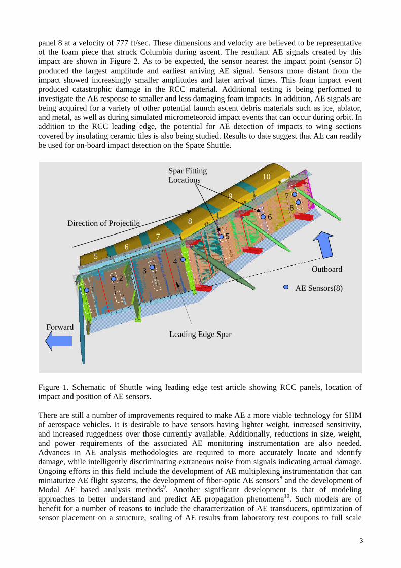
panel 8 at a velocity of 777 ft/sec. These dimensions and velocity are believed to be representative of the foam piece that struck Columbia during ascent. The resultant AE signals created by this impact are shown in Figure 2. As to be expected, the sensor nearest the impact point (sensor 5) produced the largest amplitude and earliest arriving AE signal. Sensors more distant from the impact showed increasingly smaller amplitudes and later arrival times. This foam impact event produced catastrophic damage in the RCC material. Additional testing is being performed to investigate the AE response to smaller and less damaging foam impacts. In addition, AE signals are being acquired for a variety of other potential launch ascent debris materials such as ice, ablator, and metal, as well as during simulated micrometeoroid impact events that can occur during orbit. In addition to the RCC leading edge, the potential for AE detection of impacts to wing sections covered by insulating ceramic tiles is also being studied. Results to date suggest that AE can readily be used for on-board impact detection on the Space Shuttle.
0
7
5
7
2
)
d
e
d
r
Figure 1. Schematic of Shuttle wing impact and position of AE sensors. There are still a number of improvemeof aerospace vehicles. It is desirable tand increased ruggedness over those cand power requirements of the assoAdvances in AE analysis methodolodamage, while intelligently discriminatOngoing efforts in this field include thminiaturize AE flight systems, the deveModal AE based analysis methods9
approaches to better understand and pbenefit for a number of reasons to inclsensor placement on a structure, scalin
Leading Edge Spa
Spar FittingLocations
Forwar
Direction of Projectil
leading edge test article showing RCC pa
nts required to make AE a more viable techo have sensors having lighter weight, increurrently available. Additionally, reductionsciated AE monitoring instrumentation a
gies are required to more accurately locing extraneous noise from signals indicatinge development of AE multiplexing instrumlopment of fiber-optic AE sensors8 and the
. Another significant development is thredict AE propagation phenomena10. Suc
ude the characterization of AE transducersg of AE results from laboratory test coup
Outboar
AE Sensors(8
13
45
6
86
8
9
1
nels, location of
nology for SHM ased sensitivity, in size, weight, re also needed. ate and identify actual damage.
entation that can development of at of modeling h models are of , optimization of ons to full scale
3

structures, and the development of new and automated AE data analysis methods.
30 35 40 45 50 55 60
Am
plitu
de (0
.5 V
olts
/div
isio
n)
Time (ms)
Sensor 1
Sensor 2
Sensor 3
Sensor 4
30 35 40 45 50 55 60
Am
plitu
de (0
.5 V
olts
/div
isio
n)
Time (ms)
Sensor 5
Sensor 6
Sensor 7
Sensor 8
Figure 2. AE signals from foam impact on Shuttle RCC wing leading edge. 2.2 Fiber-Optic Sensors Considering the large area of aerospace vehicle structural elements, extremely large numbers of sensors will be required for on-board structural integrity assessment. Fiber optic sensors have been identified as a leading candidate technology for meeting this requirement with minimal weight penalty. Numerous sensor sites can be multiplexed along a single optical fiber, mitigating the complexity and weight inherent with the wiring required for a large number of single ended sensors. Fiber optic sensors also provide other advantages such as the ability to measure many different structural parameters of interest, immunity to electromagnetic interference (EMI), and the ability to operate over very large range of temperature environments. Fiber optic sensors can be separated into two classes for discrete strain and temperature measurement: cavity-based designs and grating-based designs11. Cavity-based designs utilize an interferometric cavity in the fiber to create the sensor. Examples include the extrinsic Fabry-Perot interferometer (EFPI), the intrinsic or fiber Fabry-Perot interferometer (IFPI or FFPI), and all other etalon-type devices. Although such sensor designs have been utilized in a wide variety of applications such as in high temperature and EMI environments, they do not allow for multiplexing capability in a single fiber, and thus, may be limited for applications requiring large number of sensors. Grating-based designs utilize a photo- or heat-induced periodicity in the fiber core refractive index to create a sensor whose reflected or transmitted wavelength is a function of this periodicity. Grating-based sensors (e.g., Bragg gratings) can be easily multiplexed by using gratings of different wavelength as in the case of wavelength division multiplexing (WDM). Factors limiting the number of sensors in a single fiber include the limited bandwidth of the source as well as that supported by the fiber, and the range over which the physical parameter of interest is being measured. Another grating-based system developed at NASA Langley12-16 has the ability to multiplex hundreds or thousands of Bragg gratings in a single fiber. The system is based on the principle of optical frequency domain reflectometry (OFDR) and essentially eliminates the bandwidth limitations imposed by the WDM technique because all of the gratings are of nominally the same wavelength. Writing gratings at the same wavelength greatly simplifies manufacturing of the sensing fiber. Typical Bragg grating readout systems require gratings with much higher reflectivities. However, the OFDR employs a coherent detection scheme and is capable of reading
4

out very low reflectivity gratings. This allows the recording and analysis of strain or temperature from a large number of gratings in a single fiber. In fact, the OFDR is sensitive enough to measure strains by using Rayleigh scattering from the fiber core17 in lieu of a Bragg grating. By tracking wavelength changes in individual gratings, one is able to measure mechanically or thermally induced strains in the grating. In addition, by applying a coating to the fiber that is strained in the presence of a chemical of interest, it is possible to use this Bragg grating measurement system to provide high density chemical sensing. NASA Langley has demonstrated this approach for the sensing of hydrogen using palladium coatings. A sensing system of this type was flight tested on the Space Shuttle1,18. One concern of optical fiber sensors has been that of fragility. However, recent testing has demonstrated the survivability of fiber Bragg grating sensors under cryogenic exposure through numerous liquid helium cryogenic cycles on composite cryotank y-joint test articles4. The y-joint represents a critical region of composite cryotanks being developed by Northrop Grumman Corporation (NGC) for the Next Generation Launch Technology (NGLT) Program. The specimens consisted of outer skirt and inner dome graphite epoxy composite skin layers bonded to a honeycomb substrate in a sandwich configuration as shown in Figure 3a). They were instrumented with both Bragg gratings and conventional foil strain gages and measurements were taken during loading under cryogenic conditions at –420 degrees F. Three optical sensing fibers were bonded on both the dome and the skirt along with conventional strain gages. Each fiber contained approximately 15 Bragg gratings 10 cm apart. Fiber optic strain measurements were performed throughout the 10 test sequences for a total of 400 load cycles simulating NGLT cryogenic fuel tank environments. Each test sequence consisted of cooling the sample from room temperature to –420 degrees F, cycling the dome plate load 40 times from zero to 100% limit load of 18,360 pounds, then warming back to room temperature. The graph in Figure 3b) shows the close agreement of a fiber optic strain measurement to that of a conventional strain gage measurement obtained during these tests. Fiber optic thermal compensation data was obtained through apparent strain testing in which the test article was cooled to liquid helium temperature prior to applying load. There was little degradation in the performance of the fiber-optic sensors, indicating that they are reliable and suitable for cryogenic applications, even for inner mold line applications. Northrop Grumman reported that the fiber optic Bragg grating strain sensors offer an alternative method to conventional strain sensors, which often fail near cryogenic temperatures.
0
500
1000
1500
2000
2500
3000
0 5000 10000 15000 20000
Strain GageFiber-Optic Strain Gage
µstra
in
Load (lbs) a) b) Figure 3. a) Composite y-joint test specimen with optical fiber and conventional strain gages and b) Comparison of fiber optic Bragg sensor and adjacent conventional strain gage response 2.3 Wireless Sensors One critical issue in adding SHM sensors to aerospace vehicles, particularly for retrofitting to existing vehicles, is that of wiring. Wiring adds weight and complexity to the vehicle. Additionally,
5

wire degradation due to wear, excessive heating, and chemical exposure can lead to loss of sensor data, or worse, cause damage from arcing or fire. Wire degradation has resulted in major aircraft accidents as well as delays in launches of space vehicles. A novel wireless measurement system is under development that alleviates many of these shortcomings19-21. Key to this method is the use of magnetic field response sensors designed as passive inductor-capacitor circuits. The sensors produce magnetic field responses that change correspondingly to states of physical properties for which the sensors measure. Power is wirelessly provided to the sensing element by using time varying magnetic fields (Faraday induction). A radio frequency antenna produces a time-varying magnetic field used for powering the sensor as well as receiving the magnetic field response of the sensor. An interrogation system for discerning changes in the sensor response frequency, resistance and amplitude has been developed. Multiple sensors can be interrogated using this method. The method eliminates the need to have a data acquisition channel dedicated to each sensor and does not require the sensors to be near the acquisition hardware. Methods of developing sensors exploit geometric or environmental changes to the sensor. For example, capacitor geometric changes or dielectric changes (e.g., due to the presence of chemical species or due to a material phase transition), inductor geometric or inductor permeability changes of a sensor will result in magnetic field response frequency change. The method has the potential for acquiring many different types of measurements. The interrogation system under development allows for acquiring measurements from any magnetic field response sensor developed to exploit the aforementioned phenomena. The system also allows for autonomous sensor interrogation, analysis of collected response to value of physical state and comparison of current measurements with prior measurements to produce dynamic measurements. The interrogation system has two key facets: the hardware for producing a varying magnetic field at a prescribed frequency and algorithms for controlling the magnetic field produced and analyzing sensor responses. The sensors are neither connected to a power source, silicon-based processor or any data acquisition equipment. The inherent design of the sensor and the means of powering the sensors eliminate the potential for arcing. The measurement acquisition system and sensors are extremely lightweight. The system can greatly increase the number of measurements performed while alleviating the weight penalty. Measurement complexity and probability of failure are greatly reduced. Because the functionality of the sensors is based upon magnetic fields, they have potential use at cryogenic temperatures, extremely hot temperatures, harsh chemical environments and in high radiation environments. Furthermore, the method allows acquiring measurements that were previously unattainable or logistically difficult because there was no practical means of getting power and data acquisition electrical connections to a sensor. The system eliminates many “wire” issues such as weight, degradation, aging and wear. To date, sensors that have been developed using this concept are position, dielectric level (e.g., fluid level or solid particle level), load (shear, axial, torsion), angular orientation, material phase transition, moisture, exposure to various chemicals, rotation/displacement measurements, bond separation, proximity sensing, contact, pressure, strain and crack detection. The method has an interrogation distance of 9 ft using 1.0 W and 11 ft using 1.5 W of power when separate transmission and receiving antennae are used. The measurement acquisition method can be used even when the sensor is embedded in material that transmits the radio frequency energy that interrogates the sensing element. An advantage of this method is that the sensor components can be non-obtrusively added to the vehicle for which it is being used. An antenna can be produced as a metallic foil or as metal deposited on a thin dielectric film. Either version of the antenna can be mounted to an existing bulkhead or other structural components. For some applications, sensors can be fabricated using metal deposition methods. Metal deposition can be used to add sensors to a vehicle during manufacturing.
6

An example of a magnetic field response fluid-level sensor is shown in Figure 4a). The sensor consists of two capacitive plates electrically coupled to an inductor. The capacitor was placed in a cylindrical container while the inductor remained outside the container. The container was filled with hydraulic fluid. As the fluid filled the void between the plates, the dielectric exposure increased proportional to fluid immersion and thus changed the sensor’s resonant frequency. Frequency measurements for two 23 cm fluid-level sensors of different widths are shown in Figure 4b). As the levels increased, the frequencies decreased. Fluid level was increased using 13 mm increments. A fluid-level of 23 cm resulted in a frequency reductions of over 1.1 MHz (3.2 mm plate width) and 0.8 MHz (1.6 mm plate width) from that of the empty container. The capacitive plates are necessary when viscous fluids are used because any residual film has a negligible effect on measurements. The amount of plate separation is designed to eliminate capillary effects.
0 5 10 15 20
7.0
6.8
6.6
6.4
6.26.0
5.8
5.65.4
Fluid level (cm)
Frequency(MHz)
5606, 1/8 in plates
1.6 mm plates
3.2 mm plates
a) b) Figure 4. a) Magnetic field response fluid-level sensor and b) Magnetic field response variation with fluid level as measured by interrogation antenna. 2.4 Carbon Nanotube Sensors Carbon nanotubes present themselves as potentially useful candidates in the development of multifunctional structural materials with embedded SHM. The high strength to weight ratio of carbon nanotubes combined with quantum transport characteristics offer intriguing possibilities for next generation material systems. Carbon nanotubes have been predicted and measured to have a Young’s modulus on the order of 1 TPa. They can also exhibit either semiconducting or metallic behavior based on the chirality of the tube and ballistically transport electrons while maintaining their spin state. Research at NASA Langley has focused on applications of such materials as structural strain and magnetic field sensors22-24. Using a nanotube placement and alignment technique based upon dielectrophoresis, sensor with small bundles of single wall carbon nanotubes as the active elements have been fabricated for such purposes24.
Tailoring of the nanotube configuration has yielded both strain and magnetic field sensitive material systems. In the first case, transfer of the circuit to a flexible substrate has been shown to enable strain measurement along the nanotube alignment direction. The long spin coherence length of carbon nanotubes is capitalized upon for the fabrication of magnetic field sensors. Coupling of the nanotubes to ferromagnetic contacts enables spin-polarized electrons to be injected into the nanotube. The scattering of such electrons at a second contact is proportional to the relative alignment of the magnetic moment directions, which can be tailored to provide measurement of the external field strength24. Figure 5 shows such an atomic force microscope image of a single wall carbon nanotube magnetic tunnel junction sensor. Experimental measurements on this sensor found a low current magnetoresistance of approximately 20% 25.
7

Single Wall Carbon Nanotubes
Ferromagnetic Contacts
Nanotube Trapping and alignment electrodes
Figure 5. Scanning probe microscope image of carbon nanotube magnetic tunnel junction for magnetic field sensing. 3. SHM DATA SYSTEMS ARCHITECTURES Onboard architectures supporting envisioned structural health monitoring concepts will be tasked with a broad range of responsibilities – responsibilities that range from low-level acquisition of raw sensor data to the safety-critical characterization of structural integrity. From a data management perspective, the architecture will provide for the interrogation and demodulation of multiplexed sensors, networking of subsystems, and the fusion, distribution, and archival of pertinent data. From a functional perspective, the architecture’s responsibilities may include identification of flight profile, warehousing of usage history, certification load levels, and repair and inspection records, as well as hosting the diagnostics and prognostics modules for damage and degradation assessment. Moreover, the architecture is expected to support SHM systems that safely, and cost-effectively, augment, or even replace, certain maintenance and inspection procedures. NASA Langley has been working with industry and academia partners to address a variety of architectural topical areas critical to the successful deployment of SHM systems. Relevant to commercial aviation, a cost benefits analysis26 showed that the implementation of a health monitoring system can significantly reduce life cycle cost for maintenance and inspection of certain structural components, and a regulatory analysis27 offered recommendations that could facilitate the introduction of health monitoring technology. Characteristics relative to architecture, such as scalability, flexibility, robustness, and extendibility, have been identified28,29 in the context of sensors, processors, interconnection networks, storage, and software. Sensor interrogation and signal demodulation aspects are being investigated specific to the Langley developed OFDR fiber optic sensing system13. An architecture concept30 specifically tailored to the OFDR is under development, and a series of simulated axial fuselage lap joints have been instrumented and tested for evaluating the architecture concept and for building a proof-of-concept diagnostic inference model that can infer the presence of growing fatigue cracks at affected and adjacent fasteners31. To exemplify the need for architectures to accommodate evolving technology, investigation is underway to replace portions of the digital signal processing function used for signal demodulation in the OFDR system with hardware that provides for direct optical AM demodulation. Efforts to develop architectures for extremely large numbers of more generic types of sensors are also under way based on a complex multi-agent system32. Such systems consist of a large number of distributed “agents”, each of which consists of a number of sensors, sufficient processing power for
8

local data acquisition and analysis, and the ability to communicate with other agents. They may be fixed (embedded in the structure) or mobile, and may form static or dynamic ad hoc networks. These agents may have information and knowledge about their local environment, but generally not about larger regions of the structure: they can solve local problems but don’t “see” the big picture. Figure 6 shows the general architecture of such a system. Each agent is assumed to control a small local group of sensors and/or active elements. System function is controlled by the communications between agents. The System Management block does not control the operation of the system; it simply provides a communication port by which system information can be made available to the outside world. Agents may be embedded or mobile, and the system of agents is likely to be heterogeneous.
Local Agent Local Agent Local Agent Local Agent
System Managementand Visualization
Local Agent Local Agent Local Agent Local Agent
System Managementand Visualization
Figure 6. Schematic diagram of the general architecture of a multi-agent structural health management system. The interactions within such a system of agents can lead to highly non-linear emergent behavior, or self-organization, of the system. Biological analog systems, such as ant nests or bee swarms, show that this emergent behavior can produce responses to system perturbations that have all the hallmarks of intelligence greater than that of any of the constituent agents. The long-term objective is to develop a system such as this to produce emergent behavior as a result of a damaging event, which encompasses the required sequence of responses: damage detection and assessment; diagnosis of the nature of the damage; prognosis for damage development and effect on structural integrity; development and initiation of an appropriate response; and monitoring of its effectiveness. An experimental test-bed has been developed to investigate and demonstrate the principles of the multi-agent approach to an intelligent health management system, and to conduct experiments with different algorithms, sensors, sensing strategies, materials, etc. In its initial development phase, the test-bed has been designed to monitor and respond to particle impacts as the only form of damage. The test-bed has been constructed as a hexagonal prism ~ 0.8 m high and the maximum distance across the hexagonal cross-section is ~ 0.8 m. Figure 7 is a schematic diagram of the test-bed structure. An aluminum frame is covered in ~ 200 mm x 200 mm aluminum sheet panels, and each such panel contains four sensing agents (or physical cells) of the multi-agent system: the prism surface contains 192 such cells. Impacts are detected and located using passive piezoelectric polymer (PVDF) sensors, of which there are 4 per cell, in the form of circular pads 2 mm in diameter bonded to the inside surface of the aluminum panels. The four sensors of each cell form a square array with 60 mm sides, which allows both detection and location of particle impacts. While some experiments were carried out with fast particles produced by a light gas gun, most have used high power laser pulses to simulate particle impacts. Each cell, or agent, also contains electronic modules for data acquisition from the sensors, processing of the sensor data, and communication with the cells four nearest neighbors. The general architecture is a two-dimensional version of Fig. 6. Further details of the physical construction of the test-bed are given in33.
9

Concept DemonstratorHardware Containing
Sensors and Physical Cells
PC Cluster forSimulating Cells
Workstation for Controllingand Monitoring Test-bed
Serial Communication Links
UDPCommunication
Link
800
mm
400 mm
Figure 7. Schematic diagram of the experimental test-bed. The hexagonal prism of the main structure is on the left. An array of PCs is present to allow additional agents to be simulated to increase the system size. The System Management workstation is shown on the right. A PC workstation is used to operate and monitor the test-bed, acting as the System Management and Visualization block of Figure 6. However, this workstation does not control the system when the agent software is running. It acts only as a display system, providing a visual indication of the state of the cells. The workstation may be used for the following: distribution of code, initialization of clock time, real-time display of network topology, dynamic display of current flow, real-time display of impact locations and severity, and display of cell damage. A number of algorithms have been developed that demonstrate relatively simple capabilities based on self-organization. The first forms a boundary around a region of the skin that has been damaged by a particle impact34. While the actual damage produced by the laser pulse “impacts” is relatively minor and well localized, more extensive damage can be simulated by a controlled degradation of the communications ability of cells surrounding the impact site. The algorithm has been shown to work well for overlapping damage regions due to multiple impacts, and when the damage region also contains a cell that has failed which, then enables damaged cells to be identified, and a continuous boundary to be formed around the damaged region. This algorithm illustrates the ability of the system to continue operating effectively in the presence of damage. It is important to recognize that there is no central processor controlling this process. The structures are determined as a result of communications between the cells: they have self-organized. Another algorithm developed creates a “minimum spanning tree” network between a number of non-critical impact sites by simulating the behavior of ants35. In this case the ants are message packets that “explore” the network of cells, from a damaged cell, searching for impact sites. Having located another damaged cell, an ant returns to its “home” cell using dead reckoning, creating a shortest path. It communicates with other “ants” by leaving a simulated pheromone trail, so that more ants gradually converge on the shortest path between two damage sites. The resultant network of shortest paths could be used, for example, for diagnostic purposes, or to direct resources to the damage sites for repair purposes. A mobile robotic agent is currently being developed, and this may follow the pheromone trails to be guided to damage sites. Also under development are algorithms that cluster damage sites according to severity, and an approach to developing self-organizing diagnostics by clustering and subsequent classification of features extracted from sensor signals, using self-organizing maps. One of the aims of this general approach is to use agents that are as simple and reliable as possible. Future developments will therefore concentrate on the implementation of simple and efficient sensing strategies as well as on the development of algorithms that produce increasingly sophisticated responses, including damage diagnosis, prognosis and remediation decisions.
10

4. STRUCTURAL ANALYSIS FOR SHM In addition to sensing and data systems architectures, a third critical component is the development of structural analysis methodologies for SHM systems. Structural analysis tools are needed to optimize the selection of the type of sensors as well as the locations of sensors on aerospace structures. Both physics based and empirical approaches are needed to analyze data to diagnose damage and for prognosis of future structural performance. Advanced data analysis approaches such as data fusion and artificial intelligence methodologies will be needed to covert raw sensor data from hundreds or thousands of multiple types of sensors, to knowledge of structural condition. One current area of structural analysis being pursued is real-time reconstruction of full-field structural displacements and internal loads. This is seen as enabling technology for structural health monitoring and actuation and control systems feedback for the next generation of aerospace vehicles. To facilitate such capabilities, load-carrying structural members need to be instrumented with a network of strain sensors, e.g., fiber optic Bragg-grating sensors. Reconstruction of a displacement vector at every material point of the structure from a set of discrete strain measurements constitutes an inverse mathematical problem. Inverse problems are ill posed in the sense that they do not necessarily satisfy conditions of existence, uniqueness, and stability. For this class of mathematical problems that use experimentally measured data known only approximately and containing random error, general methods for constructing approximate solutions that are stable under small changes in the measured data have been developed using the fundamental concept of a regularizing operator 36. Recently, a regularized least-squares variational principle has been developed by Tessler and Spangler37,38, addressing the inverse problem of reconstructing the three-dimensional displacements and internal loads in aerospace structures. The regularized variational principle is used as a basis for developing a robust and computationally efficient inverse Finite Element Method (iFEM) aimed at reconstructing the full-field displacements and internal loads in plate and shell structural models using strain data obtained from in-situ strain sensors. The formulation is based upon the minimization of a least squares functional that uses the complete set of strain measures corresponding to a first-order shear deformation theory. The error functional uses the least-squares-difference terms comprised of the strains that are expressed in terms of the displacements and the corresponding strains that are measured experimentally. All strain-displacement relations are enforced explicitly whereas the analytical and measured strains are matched in the least-squares sense. A penalty parameter controlled regularization term enforces physical constraints imposed on the transverse shear strains. By virtue of these assumptions, all strain compatibility relations are explicitly satisfied. The methodology for reconstructing the displacements does not require elastic or inertial material properties. Thus, it is equally applicable for static and dynamic loadings. Once the displacements are reconstructed, the internal loads are readily computed from strain-displacement and stress-strain relations. A constant-strain inverse shell element, labeled iMIN3, was developed and implemented into NASA’s COMET-AR39 finite element code. The element has three nodes and conventional shell-like six degrees-of-freedom at each node, i.e., three displacements and three rotations. The displacement variables are interpolated using the lowest-order C0-continuous anisoparametric functions adopted from a related Mindlin theory plate formulation40. As an illustration of the iFEM reconstruction capability, a cantilevered aluminum plate (2024-T3 alloy) of thickness 0.125 in was subjected to a static transverse force of 5.784 lb applied near the tip of the plate as shown in Fig. 8. The plate, tested in a structures laboratory, was instrumented with 28 strain rosettes positioned on the bottom surface. Both direct (forward) and inverse FEM plate analyses were performed. The direct FEM model consisted of a high-fidelity, uniform mesh of 432
11

four-node plate elements (S4R elements in ABAQUS41), whereas the inverse FEM model used a relatively coarse, low-fidelity mesh of 28 iMIN3 triangular elements that employed the experimentally measured strains to reconstruct the bending deformations of the plate.
3/4 in
9 in 1 in3 in
3 in
3/8 in
x
y
3/8 in
Strain rosetteApplied force
ClampedEdge
All dimensions in inches
10 in
3 in
1 inP
3/8 in 3/2 in 3/4 in
9 in 1 in3 in
3 in
3/8 in
x
y
3/8 in
Strain rosetteApplied force
ClampedEdge
All dimensions in inches
10 in
3 in
1 inP
10 in
3 in
1 inP
3/8 in 3/2 in
Figure 8. Cantilevered plate under transverse force. The deflection contours corresponding to the direct and inverse FEM analyses are presented in Fig. 9. As seen from the figure, the direct and inverse FEM results are in excellent agreement across the entire plate domain including the maximum values. This example illustrates that iFEM may be used effectively with fewer elements and degrees-of-freedom then the traditional direct FEM to reconstruct accurately and efficiently the structural deformation solutions from measured strains. This aspect is particularly important for real-time applications, since it ensures the required computational efficiency.
-2.701-01
-2.455-01
-2.210-01
-1.964-01
-1.719-01
-1.473-01
-1.228-01
-9.821-02
-7.366-02
-4.911-02
-2.455-02
-1.175-35
Inverse FEM(iMIN3 elements with rosettestrain measurements used)
-2.699-01
-2.454-01
-2.208-01
-1.963-01
-1.718-01
-1.472-01
-1.227-01
-9.815-02
-7.361-02
-4.908-02
-2.454-02
-1.175-35
Max. deflectionW=0.2699 in
Max. deflectionW=0.2701 in
Direct FEM(S4R ABAQUS elements used)
High-Fidelity mesh Low-Fidelity mesh
Figure 9. Deflection contours predicted by direct FEM (432 S4R elements, ABAQUS41) and inverse FEM (28 iMIN3 elements, COMET-AR39). Considering the superior predictive capability, versatility, and computational efficiency, the iFEM methodology can be regarded as essential technology for providing real-time feedback to actuation and control systems of the next generation of aerospace vehicles, as well as for applications to structural health monitoring. 5. SUMMARY AND CONCLUSIONS Extremely large numbers of a variety of sensor types will be necessary to provide real-time, on-board structural integrity assessment as part of an SHM system for aerospace vehicles. These sensors will measure a multitude of parameters including strain, temperature, load, pressure, vibration, ultrasonic waves, and local chemistry. For flight applications, such sensors will need to be extremely lightweight, as well as be able to survive rugged environments. At present, fiber optic sensing is the leading candidate for such applications because of the ability to multiplex hundreds to thousands of sensors in a single fiber. Ultrasonic sensors, utilized in both active and passive modes, are also being studied for on-board structural health monitoring. For retrofit onto existing vehicles
12

as well as new vehicles, wireless sensors offer substantial benefits in removing the weight, complexity, and potential danger of wiring. Carbon nanotube based sensors are being developed for strain and magnetic field sensing. Carbon nanotubes are also being investigated for the development of unique, high strength composite materials in which they could also serve as sensing elements as multi-functional materials. In addition to sensing, the data systems and processing architectures that will be required to support these massive numbers of diverse sensors are being considered. Analyses of requirements are being performed along with development of architectures with emphasis on the integration of fiber optic sensors with more conventional sensor types. Efforts to develop architectures for more generic types of sensors are also under way based on a complex multi-agent system. Such systems consist of a large number of distributed “agents”, each of which consists of a number of sensors, sufficient processing power for local data acquisition and analysis, and the ability to communicate with other agents. Multi-agent architectures may offer numerous advantages over centralized processing approaches in terms of robustness and reliability, and the capability to produce emergent behavior similar to biological systems. A third and equally critical element for successful SHM deployment is the development of structural analysis techniques specific to SHM. These are needed to optimize the type and placement of sensors on a structure. They are also required for robust and efficient data analysis to process the large amounts of raw sensor data into useful knowledge about the current deformation and damage state of the structure as well as prognosis on the future performance of the structure. One current area of structural analysis being pursued is real-time reconstruction of full-field structural deformations and internal loads from sparse sets of measured strain data. Inverse FEM approaches are being developed to address this critically important problem. This capability is also essential for providing real-time displacement feedback to the actuation and control systems of the next generation of aerospace vehicles, as part of structural health management systems. 6. REFERENCES [1] Integrated Vehicle Health Management (IVHM) Human Exploration and Development of
Space (HEDS) Technology Demonstration (IVHM HTD), NASA KSC Report AA 5206, March 2000.
[2] Melvin, L. D., Childers, B. A., Prosser, W. H., Moore, J. P., Froggatt, M. E., Rogoski, R. S., Bly, J., Aude, C., Wu, M. C., Zisk, E. J., Enright, E., Cassadaban, Z., Reightler, R., Bouvier, C., Sirkis, J. Iywu, T., Wegreich, R., Mouyos, W., Aibel, D., Bodan, P., and Sanders, R. G., ‘Integrated Vehicle Health Monitoring (IVHM) for Aerospace Vehicles,’ in Proceedings of the International Conference on Structural Health Monitoring, Stanford University, Stanford, CA 18-20 September 1997, pp. 705-714.
[3] Full Scale Tank Structural Health Management (SHM) System Design, NASA Contractor Report SLI-04-1038, Contract NAS8-01100, Northrop Grumman Integrated Systems, 7 May 2004.
[4] Y-Joint Structural Health Management (SHM) Test Report, NASA Contractor Report SLI-03-1039, Contract NAS8-01100, Northrop Grumman Integrated Systems, 13 May 2004.
[5] National Vision for Space Exploration, 14 January 2004. [6] M. Lin and F.-K. Chang, ‘The manufacturing of composite structures with a built-in network
of piezoceramics,’ Composite Science and Technology, 62, pp. 919-939, 2002. [7] Ghoshal, A., Martin Jr., W. N., Schulz, M. J., Chattopadhyay, A., and Prosser W.H.,
‘Simulation of Asymmetric Lamb Wave Propagation for Health Monitoring’, Accepted for Publication in Shock and Vibration, 2004.
[8] Duke, J. C., Cassino, C. D., Childers, B. A., and Prosser, W. H., ‘Characterization of an EFPI AE Sensor,’ Materials Evaluation, 61(8), pp. 935-940, 2003.
[9] Gorman, M.R., ‘Progress in Detecting Transverse Matrix Cracking Using Modal Acoustic
13

Emission,’ Review of Progress in QNDE, 17, pp. 557-564, 1998. [10] Prosser, W. H., Hamstad, M. A., Gary, J, and O’Gallagher, A, ‘Reflections of AE Waves in
Finite Plates: Finite Element Modeling and Experimental Measurements,’ Journal of Acoustic Emission, 17(1-2), pp. 37-47, 1999.
[11] Steenkiste, R. J. and Springer, G. S., Strain and Temperature Measurement with Fiber Optic Sensors, Technomic Publishing, Lancaster, PA, 1997, pp. 3-4.
[12] M. E. Froggatt, and W. Bowen, ‘Optical Time Domain Reflectometry in Optical Fiber with Reflection Delay Time Matched to the Period of the Optical Frequency Modulation,’ Appl. Opt., 37(10), pp. 1731-1734, 1998.
[13] M. E. Froggatt and J. Moore, ‘Distributed Measurement of Static Strain in an Optical Fiber with Multiple Bragg Gratings at Nominally Equal Wavelengths,’ Appl. Opt., 37(10), pp. 1741-1746, 1998.
[14] M. E. Frogatt, U.S. patent 5,789,521, ‘Apparatus and Method for Measuring Strain in Bragg Gratings,’ 28 August 1998.
[15] M. E. Froggatt, ‘Distributed Measurement of the Complex Modulation of a Photoinduced Bragg Grating in an Optical Fiber,’ Appl. Opt., 35(25), pp. 5162-5164, 1996.
[16] B. A. Childers, M. E. Froggatt, S. G. Allison, T.C.Moore, D.A.Hare, C.F.Batten,, D.C.Jegley, ‘Use of 3000 Bragg grating strain sensors distributed on four eight-meter optical fibers during static load testing of a composite structure’, Proceedings, SPIE’s 8th Annual International Symposium on Smart Structures and Materials, Newport Beach, California, 4332, Paper No. 4332-17, 2001.
[17] M. E. Froggatt and J. Moore, ‘High Spatial-Resolution Distributed Strain Measurement in Optical Fiber with Rayleigh Scatter,’ Appl. Opt., 37(10), pp. 1735-1740, 1998.
[18] J. P. Moore, B. A. Childers, M. E. Froggatt, A. L. Cook, N. C. Coffee, L. J. Coen, J. K. Diamond, P. T. Huynh, E. M. Riley, S. K. Stover, K. G. Vipavetz, J. E. Wells, K. L. Woodman, C. D. Armistrong, J. S. Sirkis, Y. T. Peng, ‘An Overview of the Fiber Optic Sensing System for Hydrogen Leak Detection in the Space Shuttle Discovery on STS-96’, OSA Proceedings Bragg Gratings, Photosensitivity and Poling in Glass Waveguides, Stuart FL, Sep. 23-25, 1999.
[19] Woodard, S. E., Taylor, B. D., Shams, Q. A., Fox, R. L. and Bryant, R. G., ‘Magnetic Field Response Measurement Acquisition System,’ Submitted to U. S. Patent and Trademark Office and to the World Intellectual Property Organization (for international protection) on April 30, 2004. U. S. Patent Application number 10/839,445.
[20] Woodard, S. E. and Taylor, B. D., ‘Magnetic Field Response Sensor for Conductive Media,’ NASA Invention Disclosure LAR 16571-1, Submitted to U. S. Patent and Trademark Office and to the World Intellectual Property Organization (for international protection) on April 30, 2004. U. S. Patent Application number 10/839,448.
[21] Woodard, S. E., Taylor, B. D., Shams, Q. A., and Fox, R. L., ‘L-C Measurement Acquisition Method For Aerospace Systems,’ Proceedings of the 2003 AIAA Aviation Technology, Integration and Operations Technical Forum, Denver,CO, AIAA Paper No. 2003-6842, 2003.
[22] B. Wincheski, M. Namkung, J. Smits, P. Williams, and R. Harvey, ‘Effect of Alignment on Transport Properties of Carbon Nanotube/Metallic Junctions.’ Mat. Res. Soc. Symp. Proc., 772, Materials Research Society, M9.2.1, 2003.
[23] B. Wincheski, M. Namkung, S.M. Paik and J. Smits, ‘Carbon Nanotube Based Magnetic Tunnel Junctions for Electromagnetic Nondestructive Evaluation,’ Mat. Res. Soc. Symp. Proc., 721, Materials Research Society, E6.10.1, 2002.
[24] J. Smits, B. Wincheski, J. Ingram, N. Watkins, and J. Jordan, ‘In-Plane Deformations of Single Walled Carbon Nanotubes and its Effect on Electron Transport,’ Presented at Mat. Res. Soc Fall Meeting, Boston MA, 2003.
[25] B. Wincheski, M. Namkung, P. Williams, and J. Smits, ‘Four Terminal Carbon Nanotube Sensor for Magnetic Field Measurements,’ Presented at Mat. Res. Soc Spring Meeting, San
14

Francisco CA, 2004. [26] Kent, R. M., Murphy, D.A., ‘Health Monitoring System Technology Assessments: Cost
Benefits Analysis,’ NASA/CR-2000-209848, January 2000. (http://techreports.larc.nasa.gov/ltrs/PDF/2000/cr/NASA-2000-cr209848.pdf)
[27] Munns, T.E., Beard, R.E., Culp, A.M., Murphy, D.A., Kent, R.M., ‘Analysis of Regulatory Guidance for Health Monitoring,’ NASA/CR-2000-210643, December 2000. (http://techreports.larc.nasa.gov/ltrs/PDF/2000/cr/NASA-2000-cr210643.pdf)
[28] Mukkamala, R., ‘Distributed Scalable Architectures For Health Monitoring Of Aerospace Structures,’ Proceedings of the IEEE/AIAA 19th Digital Avionics Systems Conference, Philadelphia, PA, 7-13 October 2000, pp. 6.C.4.1 – 6.C.4.8.
[29] Mukkamala, R., Bhoopalam, K., Dammalpati, S., ‘Design and Analysis of a Scalable Kernel for Health Management of Aerospace Structures,’ Proceedings of the IEEE/AIAA 20th Digital Avionics Systems Conference, Daytona Beach, FL, 14-18 October 2001, pp. 3.D.2.1 – 3.D.2.10.
[30] Munns, T.E., Kent, R.M., Bartolini, A., Gause, C.B., Borinski, J.W., Dietz, J., Elster, J.L., Boyd, C., Vicari, L., Cooper, K., Ray, A., Keller, E., Venkata, V., Sastry, S.C., ‘Health Monitoring for Airframe Structural Characterization,’ NASA/CR-2002-211428, February 2002. (http://techreports.larc.nasa.gov/ltrs/PDF/2002/cr/NASA-2002-cr211428.pdf)
[31] Doggett, W., Vazquez, S., ‘An Architecture for Real-Time Interpretation and Visualization of Structural Sensor Data in a Laboratory Environment,’ Proceedings of the IEEE/AIAA 19th Digital Avionics Systems Conference, Philadelphia, PA, 7-13 October 2000, pp. 6.D.2.1 – 6.D.2.8.
[32] D.C. Price, D.A. Scott, G.C. Edwards, A. Batten, A.J. Farmer, M. Hedley, M.E. Johnson, C.J. Lewis, G.T. Poulton, M. Prokopenko, P. Valencia, P. Wang, ‘An Integrated Health Monitoring System for an Ageless Aerospace Vehicle,’ Proceedings of the 4th International Workshop on Structural Health Monitoring, Stanford, CA, September 2003 (ed. F-K. Chang) pp.310-18, 2003.
[33] M. Hedley, M. E. Johnson, C. J. Lewis, D. C. Price, ‘Testbed for Structural Health Monitoring Network’ Accepted for publication in Global Signal Processing Conference and Expo, Santa Clara, USA, Sept. 2004.
[34] H. Lovatt, G.T. Poulton, D.C. Price, M. Prokopenko, P. Valencia, P. Wang, ‘Self-organizing Impact Boundaries in Ageless Aerospace Vehicles,’ Proceedings of the 2nd International Conference on Autonomous Agents and Multi-Agent Systems (AAMAS-2003), Melbourne, Australia. July 2003.
[35] M. Prokopenko, P. Wang, M. Foreman, P. Valencia, D. C. Price, G. T. Poulton, ‘On Connectivity of Reconfigurable Impact Networks in Ageless Aerospace Vehicles,’ Journal of Robotics and Autonomous Systems, in press, 2004.
[36] Tikhonov, V., and Arsenin, V. Y., Solutions of ill-posed problems, Winston, Washington, D.C., 1977.
[37] Tessler, A. and Spangler, J. L., ‘A Variational Principle for Reconstruction of Elastic Deformations in Shear Deformable Plates and Shells,’ NASA/TM-2003-212445, 2003.
[38] Tessler, A. and Spangler, J. L.,‘Inverse FEM for Full-Field Reconstruction of Elastic Deformations in Shear Deformable Plates and Shells,’ Proceedings of Second European Workshop on Structural Health Monitoring, Munich, Germany, pp. 83-90, 2004.
[39] Moas, E. (ed.) 1997. ‘COMET-AR User’s Manual,’ NASA/CR-97-206284. [40] Tessler, A., and Hughes, T. J. R., ‘A Three-Node Mindlin Plate Element with Improved
Transverse Shear,’ Computer Methods in Applied Mechanics and Engineering, 50,
pp.71-101, 1985.
15

[41] ABAQUS/Standard User’s Manual, Version 6.3.1, Hibbitt, Karlsson, and
Sorensen, Inc.,
Pawtucket, RI, 2002.
16