Embed Size (px)
Citation preview
EUROPEAN STANDARD
NORME EUROPÉENNE
EUROPÄISCHE NORM
EN 81-43
May 2009
ICS 53.020.20; 91.140.90
English Version
Safety rules for the construction and installation of lifts - Speciallifts for the transport of persons and goods - Part 43: Lifts for
cranes
Règles de sécurité pour la construction et l'installation desélévateurs - Élévateurs particuliers destinés au transportdes personnes et des matériaux - Partie 43: Élévateurs
pour appareils de levage à charge suspendue
Sicherheitsregeln für die Konstruktion und Installation vonAufzügen - Besondere Aufzüge für den Transport von
Personen und Gütern - Teil 43: Kranführeraufzüge
This European Standard was approved by CEN on 10 April 2009.
CEN members are bound to comply with the CEN/CENELEC Internal Regulations which stipulate the conditions for giving this EuropeanStandard the status of a national standard without any alteration. Up-to-date lists and bibliographical references concerning such nationalstandards may be obtained on application to the CEN Management Centre or to any CEN member.
This European Standard exists in three official versions (English, French, German). A version in any other language made by translationunder the responsibility of a CEN member into its own language and notified to the CEN Management Centre has the same status as theofficial versions.
CEN members are the national standards bodies of Austria, Belgium, Bulgaria, Cyprus, Czech Republic, Denmark, Estonia, Finland,France, Germany, Greece, Hungary, Iceland, Ireland, Italy, Latvia, Lithuania, Luxembourg, Malta, Netherlands, Norway, Poland, Portugal,Romania, Slovakia, Slovenia, Spain, Sweden, Switzerland and United Kingdom.
EUROPEAN COMMITTEE FOR STANDARDIZATIONC O M I T É E U R O P É E N D E N O R M A LI S A T I O NEUR OP ÄIS C HES KOM ITEE FÜR NOR M UNG
Management Centre: Avenue Marnix 17, B-1000 Brussels
© 2009 CEN All rights of exploitation in any form and by any means reservedworldwide for CEN national Members.
Ref. No. EN 81-43:2009: E
EN 81-43:2009 (E)
2
Contents Page
Foreword ..............................................................................................................................................................4 Introduction .........................................................................................................................................................5 1 Scope ......................................................................................................................................................6 2 Normative references ............................................................................................................................7 3 Terms and definitions ...........................................................................................................................8 4 List of significant hazards ................................................................................................................. 11 5 Safety requirements and/or protective measures ........................................................................... 13 5.1 General ................................................................................................................................................. 13 5.2 Load combinations and calculations................................................................................................ 14 5.3 Base frame ........................................................................................................................................... 19 5.4 Mast, ties and buffers ......................................................................................................................... 19 5.5 Liftway protection and landing access ............................................................................................ 20 5.6 Car ........................................................................................................................................................ 26 5.7 Drive unit ............................................................................................................................................. 30 5.8 Electric installations and appliances ................................................................................................ 36 5.9 Control and limiting devices .............................................................................................................. 39 5.10 Breakdown conditions ....................................................................................................................... 41 6 Verification .......................................................................................................................................... 43 6.1 Verification of design ......................................................................................................................... 43 6.2 Special verification tests .................................................................................................................... 45 6.3 Verification tests on each lift before first use .................................................................................. 49 7 User information ................................................................................................................................. 49 7.1 Instruction handbook ......................................................................................................................... 49 7.2 Markings .............................................................................................................................................. 54 7.3 Marking of control elements .............................................................................................................. 56 Annex A (normative) European stormwind map ........................................................................................... 57 Annex B (normative) Electric safety devices ................................................................................................ 58 Annex ZA (informative) Relationship between this European Standard and the Essential
Requirements of EU Directive 98/37/EC ........................................................................................... 59 Annex ZB (informative) Relationship between this European Standard and the Essential
Requirements of EU Directive 2006/42/EC ....................................................................................... 60 Bibliography ..................................................................................................................................................... 61
EN 81-43:2009 (E)
3
Figures
Figure 1 — One example of forces during loading and unloading ............................................................. 15
Figure 2 — One example of a full height landing gate ................................................................................. 22
Figure 3 — Safety distances for a moving lift car, reduced height landing gates..................................... 23
Figure 4 — Reduced height landing gates ..................................................................................................... 24
Figure 5 — Correct mesh of pinion tooth ...................................................................................................... 32
Figure 6 — Minimum mesh of pinion tooth ................................................................................................... 33
Figure 7 — Correct engagement of tooth ...................................................................................................... 33
Figure 8 — Minimum engagement of tooth ................................................................................................... 33
Figure A.1 — European stormwind map ........................................................................................................ 57
Tables
Table 1 — Hazards relating to the general design and construction of lifts for persons and materials ............................................................................................................................................. 12
Table 2 — Load cases and safety factors ...................................................................................................... 17
Table 3 — Means of verification of the safety requirements and/or measures ......................................... 43
Table B.1 — List of electric safety devices .................................................................................................... 58

EN 81-43:2009 (E)
4
Foreword
This document (EN 81-43:2009) has been prepared by Technical Committee CEN/TC 10 “Lifts, escalators and moving walks”, the secretariat of which is held by AFNOR.
This European Standard shall be given the status of a national standard, either by publication of an identical text or by endorsement, at the latest by November 2009, and conflicting national standards shall be withdrawn at the latest by December 2009.
Attention is drawn to the possibility that some of the elements of this document may be the subject of patent rights. CEN [and/or CENELEC] shall not be held responsible for identifying any or all such patent rights.
This document is part of the EN 81 series of standards: "Safety rules for the construction and installation of lifts". This is the first edition.
This document has been prepared under a mandate given to CEN by the European Commission and the European Free Trade Association, and supports essential requirements of EU Directives 98/37/EC and 2006/42/EC.
For relationship with EU Directives, see informative Annexes ZA and ZB, which are integral parts of this document.
According to the CEN/CENELEC Internal Regulations, the national standards organizations of the following countries are bound to implement this European Standard: Austria, Belgium, Bulgaria, Cyprus, Czech Republic, Denmark, Estonia, Finland, France, Germany, Greece, Hungary, Iceland, Ireland, Italy, Latvia, Lithuania, Luxembourg, Malta, Netherlands, Norway, Poland, Portugal, Romania, Slovakia, Slovenia, Spain, Sweden, Switzerland and the United Kingdom.

EN 81-43:2009 (E)
5
Introduction
This document is one of a series of standards produced by CEN/TC 10/SC 1 as part of the CEN programme of work to produce machinery safety standards.
This document is a Type C standard as stated in EN ISO 12100:2003.
The machinery concerned and the extent to which hazards, hazardous situations and hazardous events are covered are indicated in the scope of this standard.
This document gives details for the complete installation.
In order to achieve a safe installation of a lift on a crane negotiations shall take place between the manufacturer of the lift and the crane user organisation about the interfaces (e.g. lift way protection, supporting structure, power supplies, suitability of alarm devices) regarding the responsibility for the supply of these requirements.
When provisions of this type C standard are different from those which are stated in type A or B standards, the provisions of this type C standard take precedence over the provisions of the other standards, for machines that have been designed and built according to the provisions of this type C standard."
EN 81-43:2009 (E)
6
1 Scope
1.1 This document specifies the safety requirements for the construction and installation of power operated lifts attached to cranes and intended for access to workplaces on cranes, by authorised persons. This includes intended use, erection, dismantling, inspection and maintenance. The lift serves defined landing levels and has a load carrying unit which is:
a) designed for the transportation of persons and goods;
b) guided;
c) travelling vertically or along a path within 15 degrees maximum from the vertical;
d) supported by rack and pinion or suspended by steel wire ropes;
e) travelling with a speed not more than 1,0 m/s for permanent lifts and not more than 0,4 m/s for temporary lifts.
1.2 This document identifies hazards as listed in Clause 4 which arise during the various phases in the life of such equipment and describes methods for the elimination or reduction of these hazards when used as intended by the manufacturer.
1.3 This document does not specify the additional requirements for:
a) operation in severe conditions (e.g. extreme climates, strong magnetic fields);
b) lightning protection;
c) operation subject to special rules (e.g. potentially explosive atmospheres);
NOTE Directive 94/9/EC concerning equipment and protective systems intended for use in potentially explosive atmospheres can be applicable to the type of machine or equipment covered by this European Standard. The present standard is not intended to provide means of complying with the essential health and safety requirements of Directive 94/9/EC.
d) electromagnetic compatibility (emission, immunity);
e) handling of loads the nature of which could lead to dangerous situations;
f) the use of combustion engines;
g) hydraulic drive units;
h) hazards occurring during manufacturing process;
i) hazards occurring as a result of being erected over a public road;
j) earthquakes;
k) noise (see also Directive on noise emissions from machines used outdoors (2000/14/EC)).
1.4 This standard is not applicable to:
a) builders hoists according to EN 12158-1:2000, EN 12158-2:2000 and EN 12159:2000;
EN 81-43:2009 (E)
7
b) elevating control stations according to EN 14502-2:2005+A1:2008;
c) lifts according to EN 81-1:1998;
d) work platforms carried on the forks of fork trucks;
e) work platforms;
f) funiculars;
g) lifts specially designed for military purposes;
h) mine lifts;
i) theatre elevators.
1.5 This standard deals with the complete lift design but excludes the design of the crane. It includes the base frame and base enclosure but excludes the design of any concrete, hard core, timber or other foundation arrangement. It includes the design of mast ties and the design of anchorage parts between the mast tie and the crane structure. This standard also includes the design of the landing gates and their fixings.
2 Normative references
The following referenced documents are indispensable for the application of this document. For dated references, only the edition cited applies. For undated references, the latest edition of the referenced document (including any amendments) applies.
EN 81-1:1998, Safety rules for the construction and installation of lifts — Part 1: Electric lifts
EN 349:1993+A1:2008, Safety of machinery — Minimum gaps to avoid crushing of parts of the human body
EN 894-1:1997+A1:2008, Safety of machinery — Ergonomic requirements for the design of displays and control actuators — Part 1: General principles for human interactions with displays and control actuators
EN 1037:1995+A1:2008, Safety of machinery — Prevention of unexpected start-up
EN 1088:1995+A2:2008, Safety of machinery — Interlocking devices associated with guards — Principles for design and selection
EN 1808:1999, Safety requirements on suspended access equipment — Design calculations, stability criteria, construction — Tests
EN 1999-1-1:2007, Eurocode 9: Design of aluminium structures — Part 1-1: General structural rules
EN 12159:2000, Builders hoists for persons and materials with vertically guided cages
EN 13001-2:2004, Cranes — General design — Part 2: Load actions
CEN/TS 13001-3-1:2004, Cranes — General design — Part 3-1: Limit states and proof of competence of steel structures
EN 13586:2004+A1:2008, Cranes — Access
EN 60204-32:2008, Safety of machinery — Electrical equipment of machines — Part 32: Requirements for hoisting machines (IEC 60204-32:2008)
EN 60529:1991, Degrees of protection provided by enclosures (IP-Code) (IEC 60529:1989)

EN 81-43:2009 (E)
8
EN 60947-4-1:2001, Low-voltage switchgear and controlgear — Part 4-1: Contactors and motor-starters — Electromechanical contactors and motor-starters (IEC 60947-4-1:2000)
EN 60947-5-1:2004, Low-voltage switchgear and controlgear — Part 5-1: Control circuit devices and switching elements — Electromechanical control circuit devices (IEC 60947-5-1:2003)
EN ISO 12100-1:2003, Safety of machinery — Basic concepts, general principles for design — Part 1: Basic terminology, methodology (ISO 12100-1:2003)
EN ISO 12100-2:2003, Safety of machinery — Basic concepts, general principles for design — Part 2: Technical principles (ISO 12100-2:2003)
EN ISO 13857:2008, Safety of machinery — Safety distances to prevent hazard zones being reached by upper and lower limbs (ISO 13857:2008)
EN ISO 14121-1:2007, Safety of machinery — Risk assessment — Part 1: Principles (ISO 14121-1:2007)
ISO 3864-1:2002, Graphical symbols — Safety colours and safety signs — Part 1: Design principles for safety signs in workplaces and public areas
ISO 4309:2004, Cranes — Wire ropes — Care, maintenance, installation, examination and discard
ISO 6336-1:2006, Calculation of load capacity of spur and helical gears — Part 1: Basic principles, introduction and general influence factors
ISO 6336-2:2006, Calculation of load capacity of spur and helical gears — Part 2: Calculation of surface durability (pitting)
ISO 6336-3:2006, Calculation of load capacity of spur and helical gears — Part 3: Calculation of tooth bending strength
ISO 6336-5:2003, Calculation of load capacity of spur and helical gears — Part 5: Strength and quality of materials
3 Terms and definitions
For the purposes of this document, the terms and definitions given in EN ISO 12100-1:2003 and the following apply.
3.1 lift machine with a car which is guided and intended for transport between different levels
3.2 working load/rated load maximum load which the lift has been designed to carry in service
3.3 rated speed travelling speed of the car in m/s for which the equipment has been designed
3.4 wire rope lift lift which uses wire rope as the load suspension system

EN 81-43:2009 (E)
9
3.5 supporting structure crane and its foundations, giving vertical or horizontal support to the mast of the lift
3.6 rack and pinion lift lift which uses a toothed rack and pinion as the load suspension system
3.7 base frame lowest framework of the lift, upon which all other components are mounted
3.8 guide rails rigid elements which determine the travel way of the load carrying unit, that may form part of the mast
3.9 mast lift mast is the structure that supports the load carrying unit
3.10 mast section indivisible piece of mast, between two adjacent mast joints
3.11 mast tie connection system between the mast of the lift and the supporting structure, providing horizontal support for the mast
3.12 liftway total space which is travelled by the load carrying unit
3.13 car load carrying unit including floor, walls, gates and roof
3.14 stopping distances distance the load carrying unit moves from the moment, when the control or safety circuit is broken until the load carrying unit has come to a full stop
3.15 overspeed safety device combination of a) overspeed detecting device and b) safety gear
a) overspeed detecting device: a device which, when the lift attains a predetermined speed causes the safety gear to be triggered/applied
b) safety gear: a mechanical device for stopping and maintaining stationary the lift car on the guide rail, rack or rope
3.16 slack rope rope, normally under tension, from which all external loads have been removed
3.17 wire rope termination adaptation at the end of a wire rope permitting attachment

EN 81-43:2009 (E)
10
3.18 landing level in the crane structure intended for loading and unloading the load carrying unit
3.19 guard rail fixed equipment, other than gates, which is used to prevent people from falling or from reaching hazardous areas
3.20 normal operation usual operating conditions for the lift when in use for carrying loads but excluding routine maintenance, erection, dismantling etc. of the lift (maintenance is considered in this standard)
3.21 in service condition during use of the lift when the load carrying unit is in any position, loaded or unloaded, moving or stationary
3.22 out of service installed condition when the load carrying unit is positioned such that it is provided with the most shelter from the wind. This is normally, but not necessarily, ground level. The load carrying unit is unloaded
3.23 competent person designated person, suitably trained, qualified by knowledge and practical experience, and provided with the necessary instructions to enable the required procedures to be carried out
3.24 overrun travel of the car beyond the normal stopping positions at its uppermost and its lowermost landing (including jumping)
3.25 authorised person competent person having permission to use the lift
3.26 safety chain safety contacts or/and safety circuits in series, stopping the machine
3.27 safety circuit device(s) instead of a safety contact (e. g. non safety contacts in combination with a safety relay)
3.28 temporary installed lifts for cranes lifts attached to tower cranes on temporary works e. g. construction sites and intended for access to workplaces by authorised persons, which shall then be removed when the construction is over
3.29 permanent installed lifts for cranes lifts attached to cranes and intended for access to workplaces by authorised persons, not covered by 3.28
3.30 safety rope steel wire rope, only carrying the load when the safety device is activated

EN 81-43:2009 (E)
11
4 List of significant hazards
This clause contains all the significant hazards, hazardous situations and events, as far as they are dealt with in this standard, identified by risk assessment as significant for this type of machinery and which require action to eliminate or reduce the risk. The significant hazards are based upon EN ISO 14121-1:2007. Also shown are the sub-clause references to the safety requirements and/or protective measures in this standard. Before using this standard it is important to carry out a risk assessment of lifts to check that it has the hazards identified in this clause.
EN 81-43:2009 (E)
12
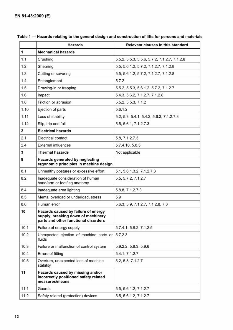
Table 1 — Hazards relating to the general design and construction of lifts for persons and materials
Hazards Relevant clauses in this standard
1 Mechanical hazards
1.1 Crushing 5.5.2, 5.5.3, 5.5.6, 5.7.2, 7.1.2.7, 7.1.2.8
1.2 Shearing 5.5, 5.6.1.2, 5.7.2, 7.1.2.7, 7.1.2.8
1.3 Cutting or severing 5.5, 5.6.1.2, 5.7.2, 7.1.2.7, 7.1.2.8
1.4 Entanglement 5.7.2
1.5 Drawing-in or trapping 5.5.2, 5.5.3, 5.6.1.2, 5.7.2, 7.1.2.7
1.6 Impact 5.4.3, 5.6.2, 7.1.2.7, 7.1.2.8
1.8 Friction or abrasion 5.5.2, 5.5.3, 7.1.2
1.10 Ejection of parts 5.6.1.2
1.11 Loss of stability 5.2, 5.3, 5.4.1, 5.4.2, 5.6.3, 7.1.2.7.3
1.12 Slip, trip and fall 5.5, 5.6.1, 7.1.2.7.3
2 Electrical hazards
2.1 Electrical contact 5.8, 7.1.2.7.3
2.4 External influences 5.7.4.10, 5.8.3
3 Thermal hazards Not applicable
8 Hazards generated by neglecting ergonomic principles in machine design
8.1 Unhealthy postures or excessive effort 5.1, 5.6.1.3.2, 7.1.2.7.3
8.2 Inadequate consideration of human hand/arm or foot/leg anatomy
5.5, 5.7.2, 7.1.2.7
8.4 Inadequate area lighting 5.8.8, 7.1.2.7.3
8.5 Mental overload or underload, stress 5.9
8.6 Human error 5.6.3, 5.9, 7.1.2.7, 7.1.2.8, 7.3
10 Hazards caused by failure of energy supply, breaking down of machinery parts and other functional disorders
10.1 Failure of energy supply 5.7.4.1, 5.8.2, 7.1.2.5
10.2 Unexpected ejection of machine parts or fluids
5.7.2.3
10.3 Failure or malfunction of control system 5.9.2.2, 5.9.3, 5.9.6
10.4 Errors of fitting 5.4.1, 7.1.2.7
10.5 Overturn, unexpected loss of machine stability
5.2, 5.3, 7.1.2.7
11 Hazards caused by missing and/or incorrectly positioned safety related measures/means
11.1 Guards 5.5, 5.6.1.2, 7.1.2.7
11.2 Safety related (protection) devices 5.5, 5.6.1.2, 7.1.2.7
EN 81-43:2009 (E)
13
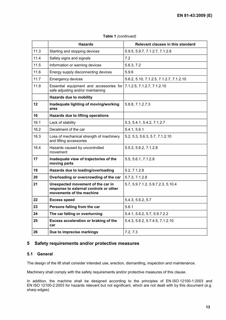
Table 1 (continued)
Hazards Relevant clauses in this standard
11.3 Starting and stopping devices 5.9.5, 5.9.7, 7.1.2.7, 7.1.2.8
11.4 Safety signs and signals 7.2
11.5 Information or warning devices 5.6.3, 7.2
11.6 Energy supply disconnecting devices 5.9.6
11.7 Emergency devices 5.6.2, 5.10, 7.1.2.5, 7.1.2.7, 7.1.2.10
11.9 Essential equipment and accessories for safe adjusting and/or maintaining
7.1.2.5, 7.1.2.7, 7.1.2.10
Hazards due to mobility
12 Inadequate lighting of moving/working area
5.8.8, 7.1.2.7.3
16 Hazards due to lifting operations
16.1 Lack of stability 5.3, 5.4.1, 5.4.2, 7.1.2.7
16.2 Derailment of the car 5.4.1, 5.6.1
16.3 Loss of mechanical strength of machinery and lifting accessories
5.2, 5.3, 5.6.3, 5.7, 7.1.2.10
16.4 Hazards caused by uncontrolled movement
5.5.3, 5.6.2, 7.1.2.8
17 Inadequate view of trajectories of the moving parts
5.5, 5.6.1, 7.1.2.8
19 Hazards due to loading/overloading 5.2, 7.1.2.8
20 Overloading or overcrowding of the car 5.7.3, 7.1.2.8
21 Unexpected movement of the car in response to external controls or other movements of the machine
5.7, 5.9.7.1.2, 5.9.7.2.3, 5.10.4
22 Excess speed 5.4.3, 5.6.2, 5.7
23 Persons falling from the car 5.6.1
24 The car falling or overturning 5.4.1, 5.6.2, 5.7, 5.9.7.2.2
25 Excess acceleration or braking of the car
5.4.3, 5.6.2, 5.7.4.5, 7.1.2.10
26 Due to imprecise markings 7.2, 7.3
5 Safety requirements and/or protective measures
5.1 General
The design of the lift shall consider intended use, erection, dismantling, inspection and maintenance.
Machinery shall comply with the safety requirements and/or protective measures of this clause.
In addition, the machine shall be designed according to the principles of EN ISO 12100-1:2003 and EN ISO 12100-2:2003 for hazards relevant but not significant, which are not dealt with by this document (e.g. sharp edges)
EN 81-43:2009 (E)
14
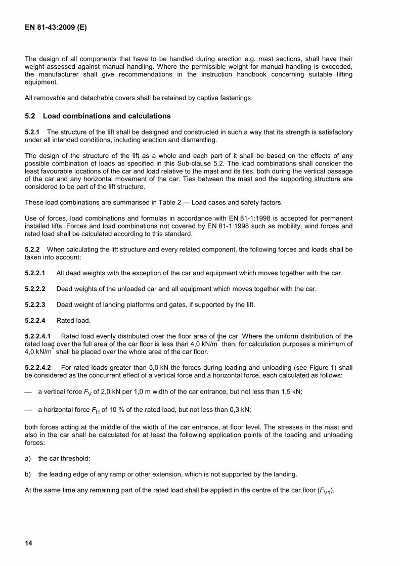
The design of all components that have to be handled during erection e.g. mast sections, shall have their weight assessed against manual handling. Where the permissible weight for manual handling is exceeded, the manufacturer shall give recommendations in the instruction handbook concerning suitable lifting equipment.
All removable and detachable covers shall be retained by captive fastenings.
5.2 Load combinations and calculations
5.2.1 The structure of the lift shall be designed and constructed in such a way that its strength is satisfactory under all intended conditions, including erection and dismantling.
The design of the structure of the lift as a whole and each part of it shall be based on the effects of any possible combination of loads as specified in this Sub-clause 5.2. The load combinations shall consider the least favourable locations of the car and load relative to the mast and its ties, both during the vertical passage of the car and any horizontal movement of the car. Ties between the mast and the supporting structure are considered to be part of the lift structure.
These load combinations are summarised in Table 2 — Load cases and safety factors.
Use of forces, load combinations and formulas in accordance with EN 81-1:1998 is accepted for permanent installed lifts. Forces and load combinations not covered by EN 81-1:1998 such as mobility, wind forces and rated load shall be calculated according to this standard.
5.2.2 When calculating the lift structure and every related component, the following forces and loads shall be taken into account:
5.2.2.1 All dead weights with the exception of the car and equipment which moves together with the car.
5.2.2.2 Dead weights of the unloaded car and all equipment which moves together with the car.
5.2.2.3 Dead weight of landing platforms and gates, if supported by the lift.
5.2.2.4 Rated load.
5.2.2.4.1 Rated load evenly distributed over the floor area of the car. Where the uniform distribution of the rated load over the full area of the car floor is less than 4,0 kN/m
2 then, for calculation purposes a minimum of
4,0 kN/m2 shall be placed over the whole area of the car floor.
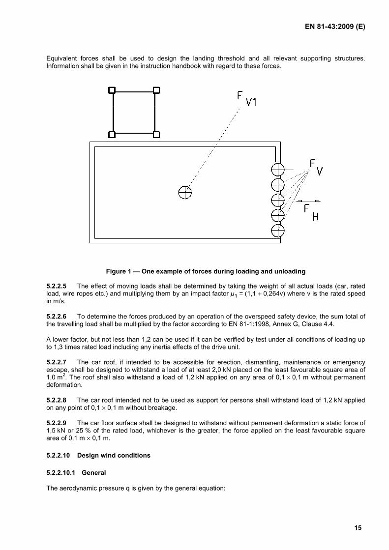
5.2.2.4.2 For rated loads greater than 5,0 kN the forces during loading and unloading (see Figure 1) shall be considered as the concurrent effect of a vertical force and a horizontal force, each calculated as follows:
a vertical force FV of 2,0 kN per 1,0 m width of the car entrance, but not less than 1,5 kN;
a horizontal force FH of 10 % of the rated load, but not less than 0,3 kN;
both forces acting at the middle of the width of the car entrance, at floor level. The stresses in the mast and also in the car shall be calculated for at least the following application points of the loading and unloading forces:
a) the car threshold;
b) the leading edge of any ramp or other extension, which is not supported by the landing.
At the same time any remaining part of the rated load shall be applied in the centre of the car floor (FV1).
EN 81-43:2009 (E)
15
Equivalent forces shall be used to design the landing threshold and all relevant supporting structures. Information shall be given in the instruction handbook with regard to these forces.
Figure 1 — One example of forces during loading and unloading
5.2.2.5 The effect of moving loads shall be determined by taking the weight of all actual loads (car, rated load, wire ropes etc.) and multiplying them by an impact factor µ1 = (1,1 + 0,264v) where v is the rated speed in m/s.
5.2.2.6 To determine the forces produced by an operation of the overspeed safety device, the sum total of the travelling load shall be multiplied by the factor according to EN 81-1:1998, Annex G, Clause 4.4.
A lower factor, but not less than 1,2 can be used if it can be verified by test under all conditions of loading up to 1,3 times rated load including any inertia effects of the drive unit.
5.2.2.7 The car roof, if intended to be accessible for erection, dismantling, maintenance or emergency escape, shall be designed to withstand a load of at least 2,0 kN placed on the least favourable square area of 1,0 m2. The roof shall also withstand a load of 1,2 kN applied on any area of 0,1 × 0,1 m without permanent deformation.
5.2.2.8 The car roof intended not to be used as support for persons shall withstand load of 1,2 kN applied on any point of 0,1 × 0,1 m without breakage.
5.2.2.9 The car floor surface shall be designed to withstand without permanent deformation a static force of 1,5 kN or 25 % of the rated load, whichever is the greater, the force applied on the least favourable square area of 0,1 m × 0,1 m.
5.2.2.10 Design wind conditions
5.2.2.10.1 General
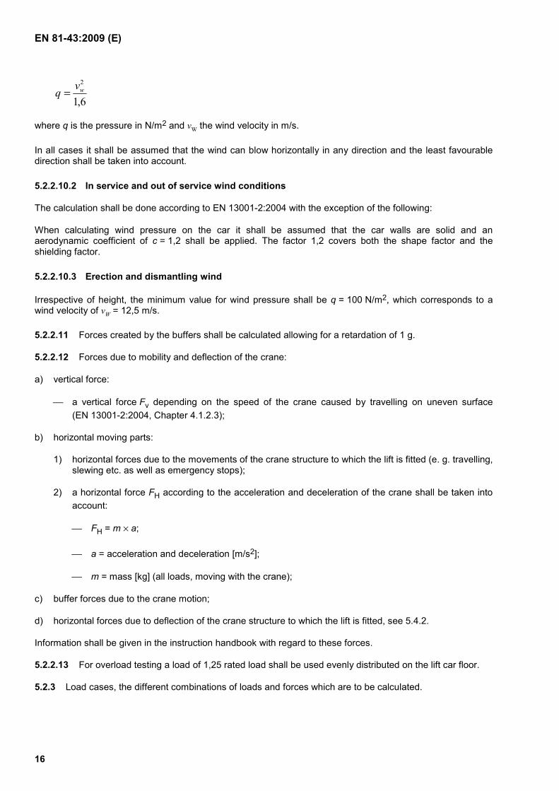
The aerodynamic pressure q is given by the general equation:
EN 81-43:2009 (E)
16
6,1
2wvq =
where q is the pressure in N/m2 and vW the wind velocity in m/s.
In all cases it shall be assumed that the wind can blow horizontally in any direction and the least favourable direction shall be taken into account.
5.2.2.10.2 In service and out of service wind conditions
The calculation shall be done according to EN 13001-2:2004 with the exception of the following:
When calculating wind pressure on the car it shall be assumed that the car walls are solid and an aerodynamic coefficient of c = 1,2 shall be applied. The factor 1,2 covers both the shape factor and the shielding factor.
5.2.2.10.3 Erection and dismantling wind
Irrespective of height, the minimum value for wind pressure shall be q = 100 N/m2, which corresponds to a wind velocity of vW = 12,5 m/s.
5.2.2.11 Forces created by the buffers shall be calculated allowing for a retardation of 1 g.
5.2.2.12 Forces due to mobility and deflection of the crane:
a) vertical force:
a vertical force Fv depending on the speed of the crane caused by travelling on uneven surface (EN 13001-2:2004, Chapter 4.1.2.3);
b) horizontal moving parts:
1) horizontal forces due to the movements of the crane structure to which the lift is fitted (e. g. travelling, slewing etc. as well as emergency stops);
2) a horizontal force FH according to the acceleration and deceleration of the crane shall be taken into account:
FH = m × a;
a = acceleration and deceleration [m/s2];
m = mass [kg] (all loads, moving with the crane);
c) buffer forces due to the crane motion;
d) horizontal forces due to deflection of the crane structure to which the lift is fitted, see 5.4.2.
Information shall be given in the instruction handbook with regard to these forces.
5.2.2.13 For overload testing a load of 1,25 rated load shall be used evenly distributed on the lift car floor.
5.2.3 Load cases, the different combinations of loads and forces which are to be calculated.
EN 81-43:2009 (E)
17
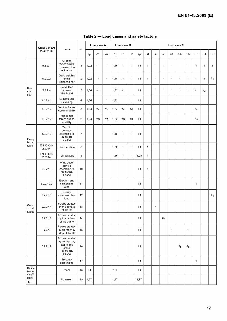
Table 2 — Load cases and safety factors
Clause of EN 81-43:2009 Loads No.
Load case A Load case B Load case C
γp A1 A2 γp B1 B2 γp C1 C2 C3 C4 C5 C6 C7 C8 C9
Nor-mal use
5.2.2.1
All dead weights with the exception
of the car
1 1,22 1 1 1,16 1 1 1,1 1 1 1 1 1 1 1 1 1
5.2.2.2 Dead weights
of the unloaded car
2 1,22 µ1 1 1,16 µ1 1 1,1 1 1 1 1 1 1 µ1 µ2 µ1
5.2.2.4 Rated load
evenly distributed
3 1,34 µ1 1,22 µ1 1,1 1 1 1 1 1 µ1 µ2
5.2.2.4.2 Loading and unloading 4 1,34 1 1,22 1 1,1
5.2.2.12 Vertical forces due to mobility 5 1,34 φ4 φ4 1,22 φ4 φ4 1,1 φ4
5.2.2.12 Horizontal
forces due to mobility
6 1,34 φ5 φ5 1,22 φ5 φ5 1,1 φ5
Exceptional force
5.2.2.10
Wind in services
according to EN 13001-
2:2004
7 1,16 1 1 1,1
EN 13001-2:2004 Snow and ice 8 1,22 1 1 1,1 1
EN 13001-2:2004 Temperature 9 1,16 1 1 1,05 1
Occas-ional forces
5.2.2.10
Wind out of service
according to EN 13001-
2:2004
10 1,1 1
5.2.2.10.3 Erection and dismantling
wind 11 1,1 1
5.2.2.13 Evenly
distributed test load
12 1,1 µ1
5.2.2.11 Forces created by the buffers
of the lift 13 1,1 1
5.2.2.12 Forces created by the buffers of the crane
14 1,1 φ7
5.9.5 Forces created by emergency stop of the lift
15 1,1 1 1
5.2.2.12
Forces created by emergency
stop of the crane
EN 13001-2:2004
16 1,1 φ5 φ5
Erecting/ dismantling 17 1,1 1
Resis-tance Coefficient γM
Steel 18 1,1 1,1 1,1
Aluminium 19 1,27 1,27 1,27
EN 81-43:2009 (E)
18
Table 2 (continued)
γp Partial safety factor EN 13001-2:2004
γM Resistance Coefficient
φ4 Dynamic factor for loads caused by travelling on uneven surface (EN 13001-2:2004)
φ5 Dynamic factor for loads caused by acceleration of all crane drives (EN 13001-2:2004)
φ7 Dynamic factor for loads due to buffer forces (EN 13001-2:2004)
A1 Normal use of the lift and normal use of the crane (lifting and lowering crane load)
A2 Loading and unloading of the lift and normal use crane
B1 A1+ wind in service, snow and temperature
B2 A2+ wind in Service, snow and temperature
C1 Lift and crane out of service
C2 Lift contacts the buffer
C3 Crane contacts the buffer
C4 Emergency stop of the lift
C5 Emergency stop of the crane
C6 Loss of electric power
C7 Erection and dismantling of the lift
C8 Triggering of overspeed safety device (lift)
C9 Overload test with 1,25 rated load
A – Load combination A contains loads for normal use of crane and lift
B – Load combination B contains loads for normal use combined with exceptional loads
C – Load combination C contains loads for normal use combined with occasional loads
5.2.4 Proof of static strength
5.2.4.1 Generally
For the proof of static strength, consider generally CEN/TS 13001-3-1:2004 for steel. This includes guidance for the analysis of structural members and their connections (e.g. fatigue, welding, bolts). For aluminium consider EN 1999-1-1:2007.
5.2.4.2 Limit design stresses for steel and aluminium
The limit design stresses are given as:
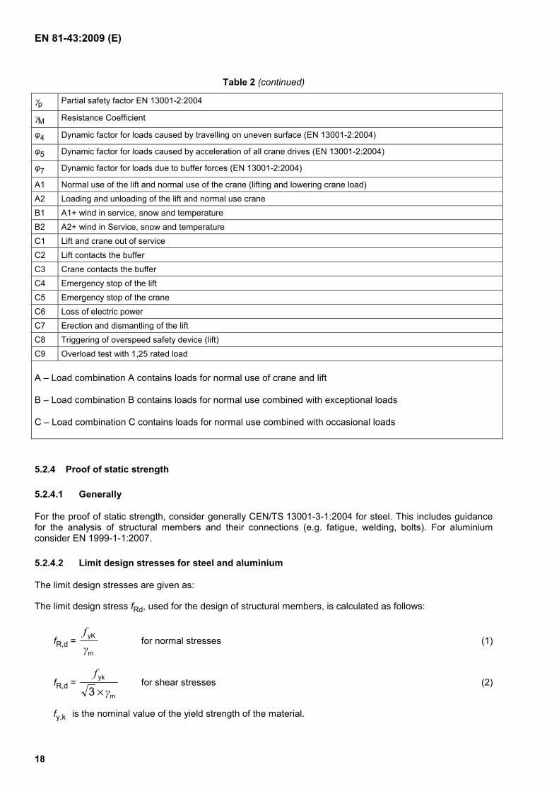
The limit design stress fRd, used for the design of structural members, is calculated as follows:
fR,d = m
yK
γf
for normal stresses (1)
fR,d = m
yk
3 γ
f
× for shear stresses (2)
fy,k is the nominal value of the yield strength of the material.
EN 81-43:2009 (E)
19
5.2.5 Fatigue stress analysis of drive and braking system components
5.2.5.1 A fatigue stress analysis shall be made for all load bearing components and joints which are critical to fatigue, such as shafts and gearing. This analysis shall take into account the degree of stress fluctuation and the number of stress cycles, which can be a multiple of the number of load cycles.
To determine the number of stress cycles, the manufacturer shall take the following into account:
a) 50 % of the movements with 50 % of the rated load in the car;
b) 50 % of the movements with empty car;
c) for the calculation of the drives each movement consists of acceleration from rest to rated speed travel at rated speed for nominal travel distance – deceleration to full stop. (see also 7.1.2.10).
For each component the least favourable combination of upwards and downwards movements shall be taken into account.
The number of movements is based on 1,6 × 10⁵ – intermittent duty (e.g. 20 years, 50 weeks per year, 80 hours per week, 1 movement per hour). Nominal travel distance shall be 35 m.
The number of movements for lifts installed on tower cranes under construction site conditions is based on 1,6 × 10⁴ – intermittent duty (e.g. 10 years, 40 weeks per year, 40 movements per week). Nominal travel distance shall be 50 m.
5.2.5.2 Each shaft shall possess a minimum safety factor of 2,0 against the appropriate endurance limit, taking into account all notch effects.
5.3 Base frame
The base frame shall be designed to accommodate all forces acting on it generated by the lift and be able to transfer them onto the supporting surface. Special consideration shall be given to the forces described in 5.2.2.12.
5.4 Mast, ties and buffers
5.4.1 Guide rails and masts
5.4.1.1 The car shall be guided by rigid guide rails and elements allowing only travel of the car in the intended direction. The car shall be guided over its full length of travel including the overrun at top and bottom.
The deflection for temporary lifts of any part of the car, guide rails and elements shall be limited such that no collision (e.g. with the landings) can occur (under all circumstances). The operational clearances specified in the standard shall always be maintained. For permanent lifts the requirements in EN 81-1:1998, Clause 10.1.2.2 applies.
5.4.1.2 Guide rails and elements shall be so designed that they can withstand all load cases as stipulated in 5.2.
5.4.1.3 Connections between individual lengths of guide rails shall maintain alignment. Loosening shall only be possible by an intentional manual action.
5.4.1.4 Connections between mast sections shall provide effective load transfer. Loosening shall only be possible by an intentional manual action.
EN 81-43:2009 (E)
20
5.4.1.5 Attachments of drive elements (e.g. rack) to the mast shall ensure that the drive element is kept in correct position so that the stipulated loads can be transferred to the mast and that the fixings are ensured from coming loose.
5.4.2 Ties for mast and guide rails
The ties shall be so designed that they take care of the movements of the supporting structures (e.g. tower crane mast) and withstand the load cases according to 5.2. Special attention shall be paid to forces generated during erection and dismantling.
5.4.3 Buffers
5.4.3.1 The travel of the car shall be limited at the bottom of its travel by buffers.
5.4.3.2 With rated load in the car and at a speed equal to triggering speed of the overspeed safety device, the average retardation of the car during action of the buffers shall not exceed 1 g, with no peak exceeding 2,5 g for more than 0,04 seconds (consider rated load in the car plus inertia effects of the motors). (see 5.2.2.11)
5.4.3.3 If fitted, oil buffers shall be provided with a means for checking the oil level. An electrical safety switch shall monitor the stroke of the oil buffer so that the car cannot be driven by the normal operating means unless the buffer is in its normal extended position.
5.5 Liftway protection and landing access
5.5.1 General
A lift, when installed for use, shall have a protected liftway and protected landings.
These shall prevent persons from being struck by moving parts, and from falling from a height.
5.5.2 Liftway protection
5.5.2.1 Where the vertical distance between any part of the car, when resting on fully compressed buffers, and an accessible base level is less than 2,5 m, a lift base enclosure shall protect all sides to a height of at least 2,0 m and shall conform to 5.5.4 and EN ISO 13857:2008, Table 1.
5.5.2.2 When, e.g. for maintenance purposes, the base enclosure is accessed by the landing gate at base level, this shall be openable from the inside without a key or any tool.
5.5.2.3 In order to prevent falling from a height down the liftway guards shall be provided in accordance with EN 13586:2004+A1:2008, Table 7.
5.5.2.4 Where it is possible to reach into the liftway, the protection shall be in accordance with EN ISO 13857:2008 except for temporary lifts with a clearance greater than 0,5 m if the rated speed is not more than 0,4 m/s
5.5.3 Landing access
5.5.3.1 When the lift is erected, it shall be provided with landing gates in the liftway protection at every point of entry including the base enclosure.
5.5.3.2 Landing gates shall not open towards the liftway.
EN 81-43:2009 (E)
21
5.5.3.3 The landing gates shall comply with the requirements in 5.5.4. Where the gate is made from imperforate material, the user shall be able to see that the car is at the landing. Requirements for indicators are given in EN 81-1:1998, Clause 7.6.2.
5.5.3.4 Horizontal and vertical sliding gates shall be guided, and their movement shall be limited by mechanical stops.
5.5.3.5 Vertical sliding gate panels shall be supported by at least two independent suspension elements. Flexible suspension elements shall possess a safety factor of at least 6 against their minimum breaking strength. Means shall be provided for retaining them in their pulleys or sprockets.
Pulleys used in connection with vertical sliding gates shall have a diameter of at least 15 times the rope diameter. Wire ropes shall be terminated according to Clause 6.6.3 and 8.11.2 of EN 1808:1999.
Any counterweight used in connection with a gate shall be guided and shall be prevented from running off the guides even in the event of failure of its suspension.
The counterweight(s) shall not be heavier than the door leaf and the force for opening and closing the door shall not exceed 50 N.
5.5.3.6 Where power operated landing gates are provided, their operation and control shall be in conformity with Clause 7.5.2 of EN 81-1:1998..
5.5.3.7 Landing gates shall not be opened or shut by a device which is mechanically, or by other means, operated by the movement of the car.
5.5.3.8 Full height gates (see Figure 2)
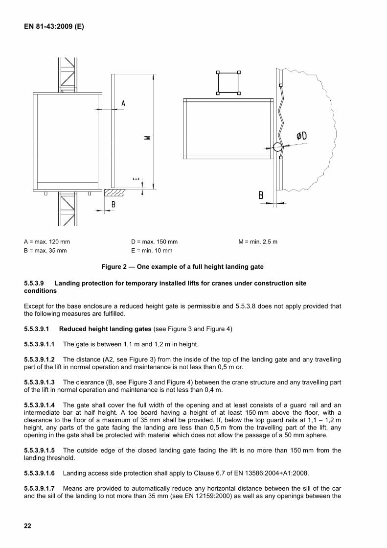
5.5.3.8.1 The height of the clear opening in the landing gate frame shall be not less than 2,0 m above the landing threshold.
5.5.3.8.2 Means shall be provided to automatically reduce any horizontal distance between the sill of the car and the sill of the landing to not more than 35 mm, as well as any openings between the car and the landing access side protection to not more than 120 mm before access can be achieved between the car and the landing.
5.5.3.8.3 The horizontal distance between the closed car gate and the closed landing gates or the access distance between the gates during the whole of their normal operation and maintenance shall not exceed 200 mm. In the case of the combination of a hinged landing door and a folding car door it shall not be possible to place a ball with a diameter of 0,15 m in any gap between the closed door.
5.5.3.8.4 The size of any perforation or opening in the liftway protection and gates, when closed, related to the clearances from adjacent moving parts shall be in accordance with EN ISO 13857:2008, Table 4.
5.5.3.8.5 Any clearances around the edges of each gate or between gate sections shall conform to EN ISO 13857:2008, Table 4 except for under the gate where the clearance shall not exceed 10 mm.
EN 81-43:2009 (E)
22
A = max. 120 mm B = max. 35 mm
D = max. 150 mm E = min. 10 mm
M = min. 2,5 m
Figure 2 — One example of a full height landing gate
5.5.3.9 Landing protection for temporary installed lifts for cranes under construction site conditions
Except for the base enclosure a reduced height gate is permissible and 5.5.3.8 does not apply provided that the following measures are fulfilled.
5.5.3.9.1 Reduced height landing gates (see Figure 3 and Figure 4)
5.5.3.9.1.1 The gate is between 1,1 m and 1,2 m in height.
5.5.3.9.1.2 The distance (A2, see Figure 3) from the inside of the top of the landing gate and any travelling part of the lift in normal operation and maintenance is not less than 0,5 m or.
5.5.3.9.1.3 The clearance (B, see Figure 3 and Figure 4) between the crane structure and any travelling part of the lift in normal operation and maintenance is not less than 0,4 m.
5.5.3.9.1.4 The gate shall cover the full width of the opening and at least consists of a guard rail and an intermediate bar at half height. A toe board having a height of at least 150 mm above the floor, with a clearance to the floor of a maximum of 35 mm shall be provided. If, below the top guard rails at 1,1 – 1,2 m height, any parts of the gate facing the landing are less than 0,5 m from the travelling part of the lift, any opening in the gate shall be protected with material which does not allow the passage of a 50 mm sphere.
5.5.3.9.1.5 The outside edge of the closed landing gate facing the lift is no more than 150 mm from the landing threshold.
5.5.3.9.1.6 Landing access side protection shall apply to Clause 6.7 of EN 13586:2004+A1:2008.
5.5.3.9.1.7 Means are provided to automatically reduce any horizontal distance between the sill of the car and the sill of the landing to not more than 35 mm (see EN 12159:2000) as well as any openings between the
EN 81-43:2009 (E)
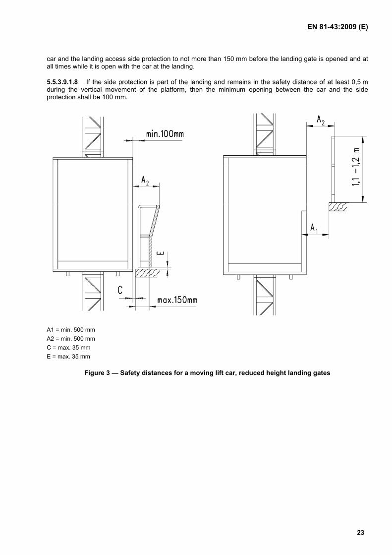
23
car and the landing access side protection to not more than 150 mm before the landing gate is opened and at all times while it is open with the car at the landing.
5.5.3.9.1.8 If the side protection is part of the landing and remains in the safety distance of at least 0,5 m during the vertical movement of the platform, then the minimum opening between the car and the side protection shall be 100 mm.
A1 = min. 500 mm A2 = min. 500 mm C = max. 35 mm E = max. 35 mm
Figure 3 — Safety distances for a moving lift car, reduced height landing gates
EN 81-43:2009 (E)
24
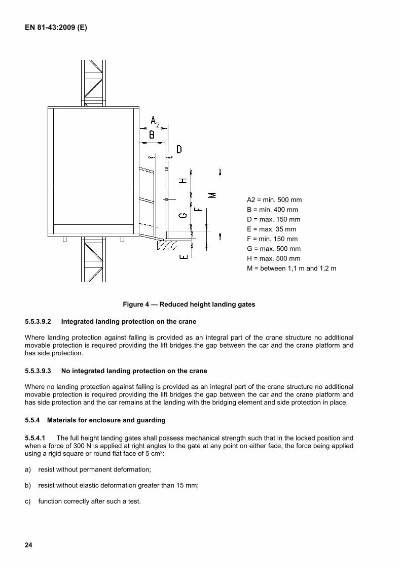
A2 = min. 500 mm B = min. 400 mm D = max. 150 mm E = max. 35 mm F = min. 150 mm G = max. 500 mm H = max. 500 mm M = between 1,1 m and 1,2 m
Figure 4 — Reduced height landing gates
5.5.3.9.2 Integrated landing protection on the crane
Where landing protection against falling is provided as an integral part of the crane structure no additional movable protection is required providing the lift bridges the gap between the car and the crane platform and has side protection.
5.5.3.9.3 No integrated landing protection on the crane
Where no landing protection against falling is provided as an integral part of the crane structure no additional movable protection is required providing the lift bridges the gap between the car and the crane platform and has side protection and the car remains at the landing with the bridging element and side protection in place.
5.5.4 Materials for enclosure and guarding
5.5.4.1 The full height landing gates shall possess mechanical strength such that in the locked position and when a force of 300 N is applied at right angles to the gate at any point on either face, the force being applied using a rigid square or round flat face of 5 cm²:
a) resist without permanent deformation;
b) resist without elastic deformation greater than 15 mm;
c) function correctly after such a test.
EN 81-43:2009 (E)
25
When a force of 600 N is applied at right angles to the gate at any point on either face, the force being applied using a rigid square or round flat face of 50 cm², it may fail the above criteria but shall remain secure and continue to provide landing protection.
5.5.4.2 The reduced height landing gates in accordance with 5.5.3.9 shall possess mechanical strength such that when a force of 1 kN is vertically applied at any point along the top of the gate, and separately when a force of 300 N is horizontally applied at any point along the top bar, the intermediate bar and the toe board, they shall:
a) resist without permanent deformation;
b) function correctly after such a test.
5.5.4.3 The liftway protection shall withstand the same force as given in 5.5.4.1 and 5.5.4.2 and also in the deflected state fulfil the requirements given in 5.5.4.2
5.5.5 Landing gate locking devices
5.5.5.1 For temporary lifts where landing gates in accordance with 5.5.3.8 (full height landing gates) are provided it shall not be possible under normal operating conditions:
to open any landing gate unless the car floor is within ± 0,25 m of that particular landing;
to start or keep in motion the car unless all landing gates are in a closed position. For permanent lifts and temporary lifts with speed higher than 0,4 m/s EN 81-1:1998, Clauses 7.7.3 and 7.7.4 applies, with exception of Clause 7.7.3.3.
5.5.5.2 Landing gates in accordance with 5.5.3.9.1 (reduced height gates) . shall be provided with a self locking device which can be manually released.
It shall not be possible under normal operating conditions to start or keep in motion the car unless all landing gates are closed and locked.
5.5.5.3 Design
5.5.5.3.1 The electrical contacts checking the closed position of the landing gate and the gate locking devices shall be safety contacts. See 5.8.6.
5.5.5.3.2 All gate locking devices fitted to gates in accordance to 5.5.5.1, together with any associated actuating mechanism and electrical contacts, shall be so situated or protected as to be accessible only to competent persons from the landing.
5.5.5.3.3 All gate locking devices fitted to reduced height gates in accordance to 5.5.5.2 shall be so built that their electric safety devices cannot be rendered inoperative without the use of tools.
5.5.5.3.4 All gate locking devices and fixings shall be capable of resisting a force of 1 kN at the level of the lock in the opening direction of the gate.
5.5.5.3.5 Gate locking devices shall be designed to permit servicing. Mechanical parts which are not tolerant of dust or water shall be protected to a minimum of IP 44 in accordance with the requirements in EN 60529:1991.
5.5.5.3.6 The removal of any detachable cover shall not disturb any of the lock mechanism or the wiring. All detachable covers shall be retained by captive fastenings.
EN 81-43:2009 (E)
26
5.5.5.3.7 The locking element shall be held in the locked position by springs or weights. Where springs are used, they shall be of the compression type and shall be guided. The failure of a spring shall not render a lock unsafe.
5.5.5.3.8 The car shall not be able to be kept in motion unless the locking elements between the gate and its restraint are engaged by not less than 7 mm.
5.5.5.3.9 In the case of flap type gate locking devices the flaps shall overlap the gate leaves with the gates closed, over the entire width, mechanical stability EN 81-1:1998¸ F 1.3.2 applies.
5.5.6 Clearances
5.5.6.1 General
All safety distances where not already stated in this standard, shall comply with EN ISO 13857:2008. All gaps shall comply with EN 349:1993+A1:2008.
5.5.6.2 Clearances beneath the car
A pit shall be provided giving sufficient space in accordance with EN 81-1:1998, Clause 5.7.3. If it is not possible to provide a pit means shall be provided to create a minimum vertical clearance (e.g. a moveable prop or equivalent) of at least 1,8 m. The clearance shall extend under the entire area of the car. It shall be possible to erect and dismantle the means provided without any person having to be beneath the car, see 7.
A limit switch in accordance with 5.8.6 shall monitor the means provided above to ensure the lift cannot move whilst the prop or equivalent is in place.
5.5.6.3 Clearances above the car
For temporally lifts:
When the car has reached its highest possible position, the free vertical distance between the level of the highest part of the car and the level of the lowest part of any structure above the car shall be at least 30 cm and space to accommodate a rectangular block not less than 0,50 m × 0,60 m × 1,0 m see also 7.1.2.7.1.3.
For permanent lifts EN 81-1:1998, Clause 5.7 applies.
5.6 Car
5.6.1 General requirements
The car shall take the form of a fully enclosed car with the exception of the case described in 5.6.1.4.1.2. The minimum interior free height shall be 2,0 m.
For each person in the car, a car floor area of 0,25 m2 shall be provided.
Each person shall be considered to weigh a minimum of 100 kg.
The car structure shall be calculated according to 5.2.
The car shall be guided to prevent disengagement or jamming.
The car shall be provided with effective devices which retain the car to the car guides in the event of the normal guide shoes or rollers failing.
EN 81-43:2009 (E)
27
The car shall be provided with mechanical means e.g. buffer to prevent it from running off the guides at extremes of travel. These means shall be in work as well during normal operation as during erection, dismantling and maintenance.
5.6.1.1 Car floor
The floor shall be designed to withstand the forces according to 5.2.2.9, be slip resistant (e.g. chequer plate) and be free draining.
5.6.1.2 Car walls
The car shall have walls extended to full height between the floor and the roof and shall conform to 5.5.4.1.
The walls shall as regards perforation meet the requirements in EN ISO 13857:2008, Table 4 but the openings shall prevent the passage of a hand.
Any hazardous projection shall be marked according to ISO 3864-1:2002.
5.6.1.3 Car roof
5.6.1.3.1 The car shall be roofed.
5.6.1.3.2 If the roof is used for erection, dismantling, maintenance or inspection of the lift itself or is provided with an emergency trapdoor it shall be slip resistant and protected with a guard-rail, see also 5.6.1.5.5.
This guard rail shall consist of an upper rail not less than 1,1 m above the roof, an intermediate rail at half height and a toeboard not less than 150 mm height from the car roof. The guard rail shall enclose such part of the car roof, that erection, maintenance or inspection may be carried out in a safe manner. The guard rail shall not be placed more than 200 mm (horizontally) inside the edge of the roof.
5.6.1.3.3 The roof structure shall be calculated according to 5.2.2.7 and 5.2.2.8.
5.6.1.3.4 If the roof is perforated, the openings shall not allow the passage of a 15 mm sphere.
5.6.1.4 Car gate
5.6.1.4.1 Manually operated gates
5.6.1.4.1.1 The gate opening shall have a clear height of at least 2,0 m and a clear width of at least 0,5 m.
The gate shall fully cover the opening.
The gates shall as regards perforations meet the requirements in EN ISO 13857:2008, Table 4 but the openings shall prevent the passage of a hand.
5.6.1.4.1.2 A reduced height car gate is permitted if all of the following conditions are met:
a) the lift is temporary installed;
b) the gate shall have a minimum height of 1,1 m with vertical clearances of no more than 0,5 m and a toe board with a height of least 0,15 m;
c) the car is only controlled by hold to run control from inside the car;
d) the rated speed is not more than 0,4 m/s;
EN 81-43:2009 (E)
28
e) the distance (A1, see Figure 3) from the inside of the car gate and the closest point of the crane structure or landing gate, is not less than 0,5 m;
the clearance (B, see Figure 4) between the crane structure and any travelling part of the lift in normal operation and maintenance is not less than 0,4 m.
5.6.1.4.1.3 Imperforate gates, when fitted shall be provided with a vision panel or indication according to EN 81-1:1998, Clause 8.6.5).
5.6.1.4.1.4 The design of gates shall be in conformity with 5.5.3.3 to 5.5.3.7 as well as 5.5.3.8.6.
5.6.1.4.1.5 On temporary lifts the gates shall be fitted with mechanical locks such that, under operating conditions it shall not be possible to open any car gate unless the car floor is within ± 0,25 m of a landing. It shall not be possible under operating conditions to start and keep in motion the car unless all car gates are in the closed position. It shall not be possible with unlocked gates under normal operation conditions to keep the car in motion unless it is inside the landing zone and the speed is 0,4 m/s or less. On permanent lifts the gate shall always be locked.
5.6.1.4.1.6 In deviation from 5.6.1.4.1.5 reduced height car gates fitted to lifts installed on tower cranes under construction site conditions shall be provided with a self locking device which can be manually released. It shall not be possible under normal operating conditions to start or keep in motion the car unless all car gates are closed and locked.
5.6.1.4.1.7 Both car gates and vision panels shall be capable of withstanding a thrust of 300 N applied normally at any position without permanent deformation and without the gates opening or being sprung from their guides. The 300 N thrust shall be applied by a rigid square or round flat face of 5 cm². Vision panel in accordance with EN 81-1:1998, Clauses 8.6.5 and 8.6.7.1 and shall:
a) resist without permanent deformation;
b) resist without elastic deformation greater than 15 mm;
c) function correctly after such a test.
5.6.1.4.1.8 Means shall be provided to reduce any horizontal distance between the sill of the car and the sill of the landing as well as any openings between the car and the landing access side protection to not more than 150 mm before the car gate can be opened unless this is achieved by the action of opening the gate.
5.6.1.4.1.9 All mechanical and electrical safety devices associated with the car entrances shall be designed as described in 5.5.5.3.1 and 5.8.6.
5.6.1.4.1.10 The car gate locking device, together with any associated actuating mechanism and electrical contacts, shall be so situated or protected as to be inaccessible from within the car with all the car gates closed. The locking devices associated with the cage door shall be situated or protected as to be inaccessible to unauthorised persons from within the car.
5.6.1.4.1.11 Power operated gates
If the car door is power operated, the power operation system shall conform to EN 81-1:1998, Clause 8.7.2.
5.6.1.5 Emergency escape
5.6.1.5.1 Means of escape from the car shall be as follows.
EN 81-43:2009 (E)
29
5.6.1.5.2 There shall be at least a car roof trapdoor or an emergency escape door which offers a means of escape in emergency, which is openable from the outside of the car without a key and from the inside of the car with a special key.
5.6.1.5.3 The locking of any emergency escape door/trapdoor shall be proved by electrical safety devices in conformity with 5.8.6. This device shall cause the lift to stop if the locking ceases to be effective. Restoring the lift to service shall only be possible after deliberate relocking the closed door.
5.6.1.5.4 Any emergency escape opening for the door in the car wall shall be at least 0,4 m × 1,4 m. Doors shall open inward or slide and give safe access to the escape route.
5.6.1.5.5 Any trapdoor opening in the roof shall be at least 0,35 m × 0,5 m and shall open outwards. A ladder, giving access to such a trapdoor, shall be permanently available inside the car.
5.6.2 Overspeed safety device against falling of the car
5.6.2.1 The overspeed safety device shall be operational at all times, including erection, dismantling and during resetting after being triggered. No regular drive component with the exception of the rack shall be used for the overspeed safety device.
5.6.2.2 An overspeed safety device shall be provided to prevent the car from falling. On permanent lift, it shall act on the guide rail, or rack. On temporary lifts, acting on safety rope is also allowed. It shall be able to stop and maintain stopped the car with 1,3 times the rated load. The overspeed safety device shall be calculated according to 5.2, especially to 5.2.2.6. For permanent lift the requirements in EN 81-1:1998, Clauses 9.8 (safety gear) and 9.9 (overspeed governor) can be used instead.
Overspeed safety device retardation with any load in the car up to the rated load shall be between 0,05 g and 1,0 g with no peak exceeding 2,5 g for more than 0,04 s.
5.6.2.3 Movement of the car by means of the normal controls shall be automatically prevented by an electric safety device according to 5.8.6 at the latest when the overspeed safety device is triggered.
5.6.2.4 It shall be possible to control the tests of the overspeed safety device from an adequate safety distance from the car.
5.6.2.5 The overspeed safety device shall be attached to the car frame and triggered directly by the overspeed of the car.
5.6.2.6 If the overspeed safety device is adjustable, the final settings shall be sealed.
5.6.2.7 An overspeed safety device shall only be triggered mechanically.
5.6.2.8 Under all conditions of loading excluding overload, when the safety device(s) operates, the floor of the car shall not incline by more than 5 % from its normal position and shall recover without permanent deformation.
5.6.2.9 The tripping speed of the overspeed safety device shall not exceed the lifts rated speed by more than 0,4 m/s.
5.6.2.10 Provision shall be made to prevent the overspeed safety device from becoming inoperative due to the accumulation of extraneous materials or to atmospheric conditions.
5.6.2.11 An overspeed safety device designed to grip more than one guide shall operate on all guides simultaneously.
EN 81-43:2009 (E)
30
5.6.2.12 In overspeed safety devices where the braking action is achieved by means of springs, the failure of any spring shall not lead to a dangerous malfunction of the overspeed safety device.
5.6.2.13 Where an overspeed detecting device (see 3.15) is not directly mounted to the car, the detecting device and the safety gear shall conform with the requirements of EN 81-1:1998, Clauses 9.8 and 9.9 (see 5.6.2).
5.6.3 Overload detection device
5.6.3.1 This standard specifies a method of detecting overload, but does not require the provision of a load-moment detecting device as moment is covered by the stability and stress calculations (5.2) in conjunction with the overload detecting device.
There shall be an overload detection device provided, which gives a clear signal by light and/or sound in the car and prevents normal starting and locking of the car and landing doors, in the event of overload in the car. The overload is considered to occur when the rated load is exceeded by 10 % with a minimum of 75 kg.
There shall be no provision for the user to cancel the warning.
Overload detection shall be carried out whilst the car is stationary and shall be deactivated under travel.
5.6.3.2 The design and installation of overload indicators and detectors shall take into account the need to test the lift with overloads without dismantling and without affecting the performance of the indicator or detector.
5.6.3.3 If interruption of the power occurs, all data and calibration of the overload detection device shall be retained.
5.6.3.4 Devices shall be protected to prevent damage from shock, vibration and the general use of lifts including erection, operation, dismantling and maintenance as well as environmental influences as intended by the manufacturer.
5.7 Drive unit
5.7.1 General provisions
5.7.1.1 Each lift shall have at least one drive unit of its own.
5.7.1.2 Each drive unit shall be calculated according to 5.2 including the specific requirements given in 5.2.5.
5.7.1.3 The drive motor shall be coupled to the drum, drive pinion, or traction sheaves by a drive unit which cannot be disengaged.
5.7.1.4 The car shall during normal operation and maintenance, be raised and lowered under power at all times.
5.7.1.5 For all lifts, the speed of the empty car upwards or of the car with rated load downwards shall not exceed the rated speed by more than 15 % under normal operating conditions.

EN 81-43:2009 (E)
31
5.7.2 Protection and accessibility
5.7.2.1 During normal operation, the safety distance to parts of the driving machinery shall be in accordance with EN ISO 13857:2008 and EN 349:1993+A1:2008.
5.7.2.2 Where guarding affords suitable protection, fixed guarding shall be provided to prevent the entry of any material that might cause damage to any part of the drive unit, e.g. gravel, rain, snow, ice, mortar and dust.
5.7.2.3 Guards shall be provided for all hazardous parts of the drive unit e.g. gear wheels, belts and chains, revolving shafts, flywheels, guide rollers, couplings and similar rotating parts unless those parts are made safe by design or by position, and the guards shall be designed to permit easy access for routine inspection and maintenance work.
For temporary installed for cranes under construction site conditions where access to the mast structure is restricted, and the car is controllable by hold to run control, 5.7.2.1 does not apply in respect of the safety distance from regular points of access to parts of the driving machinery which shall be greater than 30 cm;
5.7.3 Suspension system
5.7.3.1 Rack and pinion drive
5.7.3.1.1 General
5.7.3.1.1.1 Drive pinions and overspeed safety device pinions shall be positively fastened to their shafts. Methods involving friction and clamping shall not be used.
5.7.3.1.1.2 The safety device pinion shall be situated lower than the drive pinions.
5.7.3.1.1.3 The racks shall be securely attached. Joints in the rack shall be accurately aligned to avoid faulty meshing or damage to teeth.
5.7.3.1.1.4 Steps shall be taken to prevent the penetration of foreign bodies, that may be detrimental to safe operation, between each drive or safety pinion and the geared rack.
5.7.3.1.1.5 For other gear drives such as pin racks the same provisions as given in 5.7.3.1.1 to 5.7.3.1.4 shall be used and the same safety factors shall be ensured.
5.7.3.1.2 Design
5.7.3.1.2.1 Pinion
Each pinion shall be designed according to ISO 6336-1:2006, ISO 6336-2:2006, ISO 6336-3:2006 and ISO 6336-5:2003 with regard to tooth strength and pitting and shall take into account the requirements of 5.2.5.
Each pinion shall possess a minimum safety factor of 2,0 against the endurance limit for tooth strength, taking into account the maximum wear as stated in the manufacturer’s instruction handbook.
Each pinion shall possess a minimum safety factor of 1,4 against the endurance limit for pitting.
5.7.3.1.2.2 Rack
The rack shall be made of material having properties matching those of the pinion in terms of wear and shall be designed according to ISO 6336-1:2006, ISO 6336-2:2006, ISO 6336-3:2006 and ISO 6336-5:2003, with regard to tooth strength and pitting, and shall take into account the requirements of 5.2.5.
EN 81-43:2009 (E)
32
The rack shall possess a minimum safety factor of 2,0 against the static limit for tooth strength, taking into account the maximum wear as stated in the manufacturer’s instruction handbook.
5.7.3.1.2.3 Load distribution
When there is more than one drive pinion in mesh with the rack, then either a self-adjusting means shall be provided to effectively share the loading on each drive pinion or the drive unit shall be so designed as to accommodate all normal conditions of load distribution between the pinions.
5.7.3.1.3 Modules
The rack and pinion tooth module shall be not less than:
a) four (4) for drive units where the counter roller or other mesh control feature reacts directly on the rack without the interposition of any other mast profiles;
b) six (6) where the reaction of the counter roller or other mesh control feature is by means of another element of the mast which is then in immediate contact with the rack.
5.7.3.1.4 Rack and pinion engagement
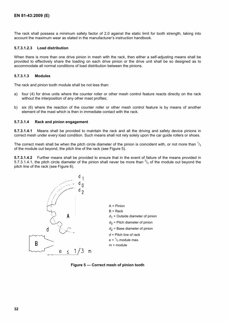
5.7.3.1.4.1 Means shall be provided to maintain the rack and all the driving and safety device pinions in correct mesh under every load condition. Such means shall not rely solely upon the car guide rollers or shoes.
The correct mesh shall be when the pitch circle diameter of the pinion is coincident with, or not more than 1/3 of the module out beyond, the pitch line of the rack (see Figure 5).
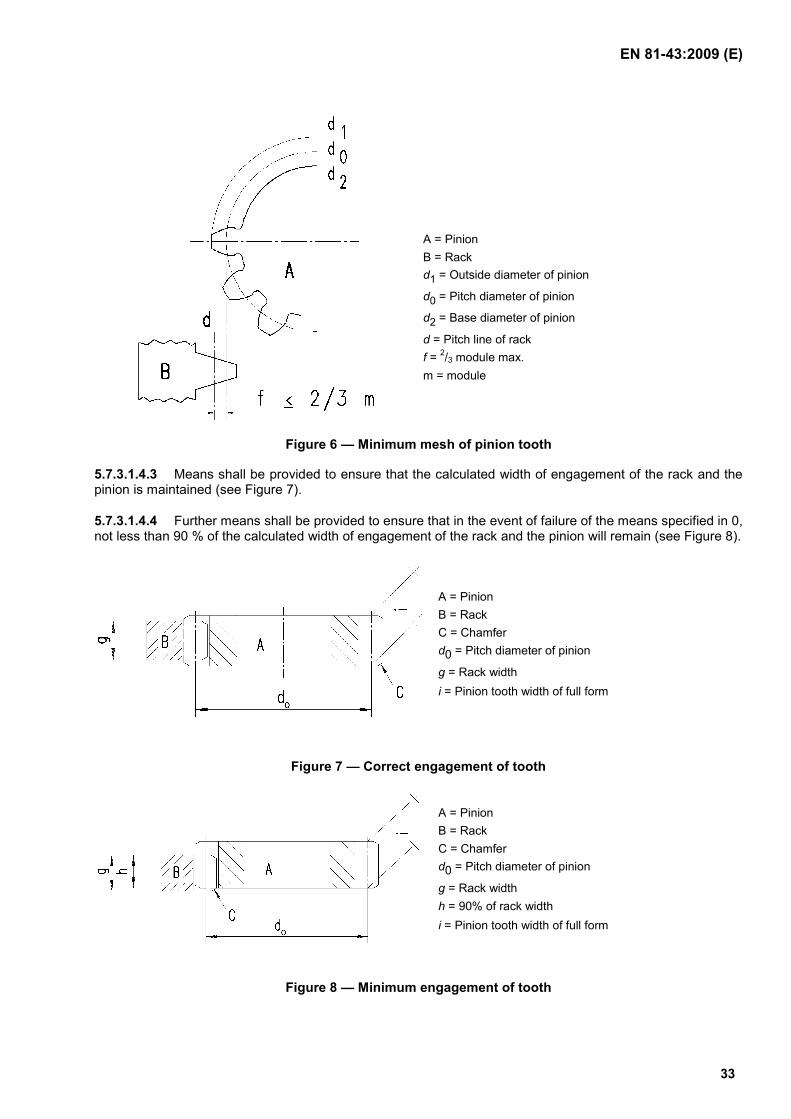
5.7.3.1.4.2 Further means shall be provided to ensure that in the event of failure of the means provided in 5.7.3.1.4.1, the pitch circle diameter of the pinion shall never be more than 2/3 of the module out beyond the pitch line of the rack (see Figure 6).
A = Pinion B = Rack d1 = Outside diameter of pinion
d0 = Pitch diameter of pinion
d2 = Base diameter of pinion
d = Pitch line of rack e = 1/3 module max. m = module
Figure 5 — Correct mesh of pinion tooth
EN 81-43:2009 (E)
33
A = Pinion B = Rack d1 = Outside diameter of pinion
d0 = Pitch diameter of pinion
d2 = Base diameter of pinion
d = Pitch line of rack f = 2/3 module max. m = module
Figure 6 — Minimum mesh of pinion tooth
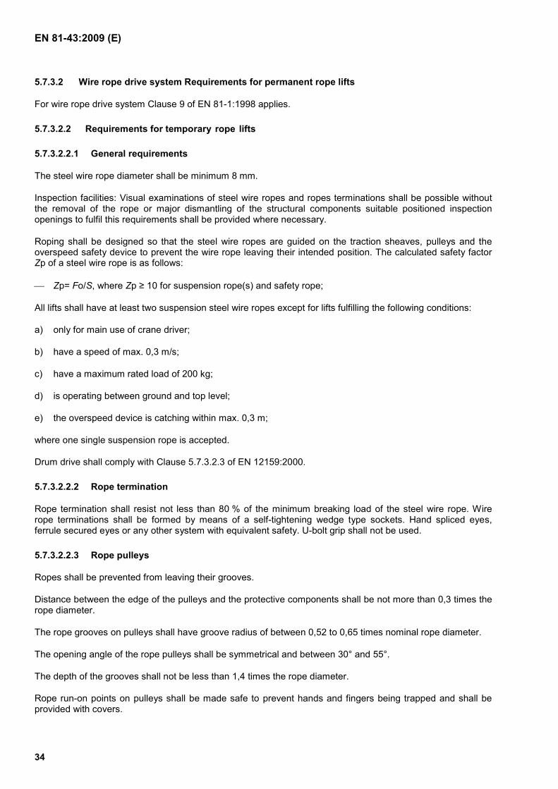
5.7.3.1.4.3 Means shall be provided to ensure that the calculated width of engagement of the rack and the pinion is maintained (see Figure 7).
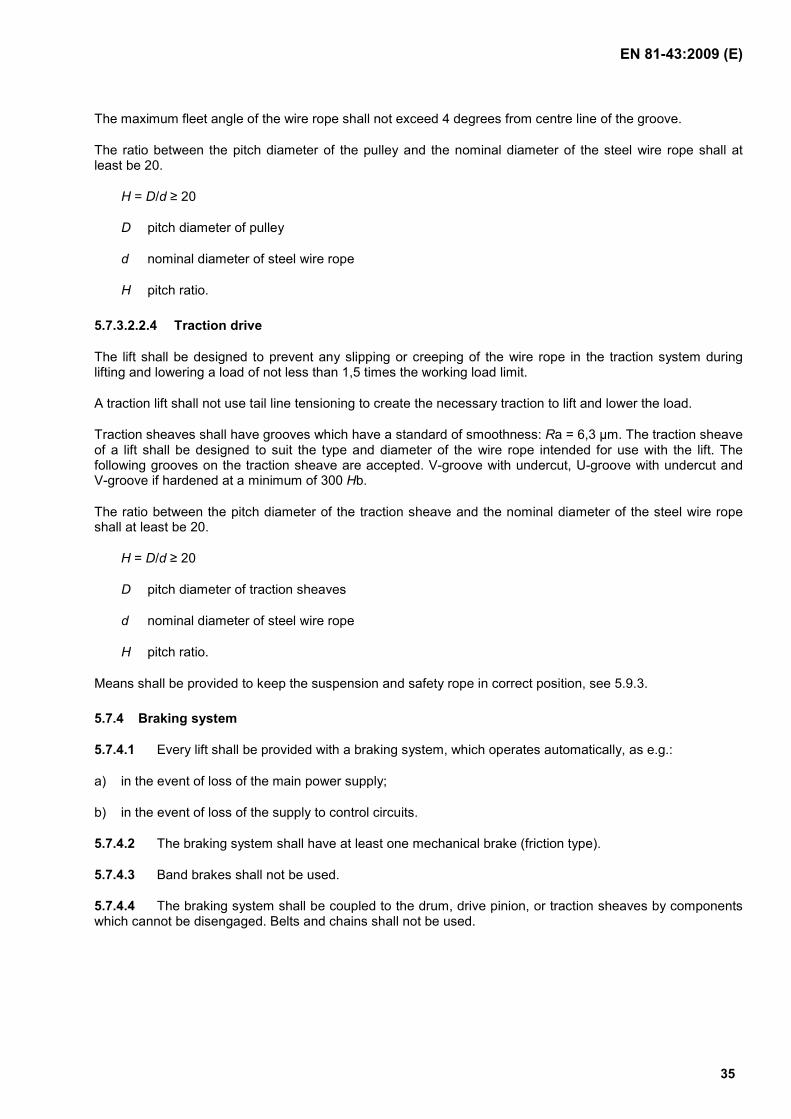
5.7.3.1.4.4 Further means shall be provided to ensure that in the event of failure of the means specified in 0, not less than 90 % of the calculated width of engagement of the rack and the pinion will remain (see Figure 8).
A = Pinion B = Rack C = Chamfer d0 = Pitch diameter of pinion
g = Rack width i = Pinion tooth width of full form
Figure 7 — Correct engagement of tooth
A = Pinion B = Rack C = Chamfer d0 = Pitch diameter of pinion
g = Rack width h = 90% of rack width i = Pinion tooth width of full form
Figure 8 — Minimum engagement of tooth
EN 81-43:2009 (E)
34
5.7.3.2 Wire rope drive system Requirements for permanent rope lifts
For wire rope drive system Clause 9 of EN 81-1:1998 applies.
5.7.3.2.2 Requirements for temporary rope lifts
5.7.3.2.2.1 General requirements
The steel wire rope diameter shall be minimum 8 mm.
Inspection facilities: Visual examinations of steel wire ropes and ropes terminations shall be possible without the removal of the rope or major dismantling of the structural components suitable positioned inspection openings to fulfil this requirements shall be provided where necessary.
Roping shall be designed so that the steel wire ropes are guided on the traction sheaves, pulleys and the overspeed safety device to prevent the wire rope leaving their intended position. The calculated safety factor Zp of a steel wire rope is as follows:
Zp= Fo/S, where Zp ≥ 10 for suspension rope(s) and safety rope;
All lifts shall have at least two suspension steel wire ropes except for lifts fulfilling the following conditions:
a) only for main use of crane driver;
b) have a speed of max. 0,3 m/s;
c) have a maximum rated load of 200 kg;
d) is operating between ground and top level;
e) the overspeed device is catching within max. 0,3 m;
where one single suspension rope is accepted.
Drum drive shall comply with Clause 5.7.3.2.3 of EN 12159:2000.
5.7.3.2.2.2 Rope termination
Rope termination shall resist not less than 80 % of the minimum breaking load of the steel wire rope. Wire rope terminations shall be formed by means of a self-tightening wedge type sockets. Hand spliced eyes, ferrule secured eyes or any other system with equivalent safety. U-bolt grip shall not be used.
5.7.3.2.2.3 Rope pulleys
Ropes shall be prevented from leaving their grooves.
Distance between the edge of the pulleys and the protective components shall be not more than 0,3 times the rope diameter.
The rope grooves on pulleys shall have groove radius of between 0,52 to 0,65 times nominal rope diameter.
The opening angle of the rope pulleys shall be symmetrical and between 30° and 55°.
The depth of the grooves shall not be less than 1,4 times the rope diameter.
Rope run-on points on pulleys shall be made safe to prevent hands and fingers being trapped and shall be provided with covers.
EN 81-43:2009 (E)
35
The maximum fleet angle of the wire rope shall not exceed 4 degrees from centre line of the groove.
The ratio between the pitch diameter of the pulley and the nominal diameter of the steel wire rope shall at least be 20.
H = D/d ≥ 20
D pitch diameter of pulley
d nominal diameter of steel wire rope
H pitch ratio.
5.7.3.2.2.4 Traction drive
The lift shall be designed to prevent any slipping or creeping of the wire rope in the traction system during lifting and lowering a load of not less than 1,5 times the working load limit.
A traction lift shall not use tail line tensioning to create the necessary traction to lift and lower the load.
Traction sheaves shall have grooves which have a standard of smoothness: Ra = 6,3 µm. The traction sheave of a lift shall be designed to suit the type and diameter of the wire rope intended for use with the lift. The following grooves on the traction sheave are accepted. V-groove with undercut, U-groove with undercut and V-groove if hardened at a minimum of 300 Hb.
The ratio between the pitch diameter of the traction sheave and the nominal diameter of the steel wire rope shall at least be 20.
H = D/d ≥ 20
D pitch diameter of traction sheaves
d nominal diameter of steel wire rope
H pitch ratio.
Means shall be provided to keep the suspension and safety rope in correct position, see 5.9.3.
5.7.4 Braking system
5.7.4.1 Every lift shall be provided with a braking system, which operates automatically, as e.g.:
a) in the event of loss of the main power supply;
b) in the event of loss of the supply to control circuits.
5.7.4.2 The braking system shall have at least one mechanical brake (friction type).
5.7.4.3 Band brakes shall not be used.
5.7.4.4 The braking system shall be coupled to the drum, drive pinion, or traction sheaves by components which cannot be disengaged. Belts and chains shall not be used.
EN 81-43:2009 (E)
36
5.7.4.5 The brake(s) on its own shall be capable of stopping the car from rated speed in down direction with 1,25 times the rated load (see also 5.6.3.4). In addition the brakes on their own shall be capable of stopping the car when travelling at the tripping speed of the overspeed governor with the rated load. Under all conditions the retardation of the car shall not exceed 1,0 g.
5.7.4.6 Mechanical requirement
5.7.4.6.1 Temporary lift slowed down by the use of brake
Every spring of the brake(s) which takes part in the application of the braking action on the drum or disc shall be constructed and installed in such a way that if a failure in one of the springs occurs, sufficient braking effort to slow down the car, when containing rated load, would continue to be exercised.
5.7.4.6.2 Permanent lifts and lifts not slowed down by the use of brake
All the mechanical components of the brake which take part in the application of the braking action on the drum or disk shall be installed in two sets. If one of the components is not working a sufficient braking effort to slow down the car, travelling downwards at rated speed and with rated load shall continue to be exercised. Any solenoid plunger is considered to be a mechanical part, any solenoid coil is not (see EN 81-1:1998, Clause 12.4.2.1 2nd and 3rd paragraph). An EN 81-1:1998 approved brake is permitted.
5.7.4.7 The action of the brake shall be exerted by compression springs. The springs shall be adequately supported and shall not be stressed in excess of 80 % of the torsional elastic limit of the material.
5.7.4.8 In normal operation and maintenance and erection and dismantling, a continuous supply of current shall be required to hold off the brake.
The interruption of the current to the brake shall be effected by at least two independent electrical devices, whether or not integral with those that cause the interruption of the current feeding the lift machine.
If, when the lift is stationary, one of the devices has not cut off the supply to the brake, further movement shall be prevented at the latest at the next change in the direction of motion.
5.7.4.9 Braking shall become effective without delay after opening of the brake release supply (the use of a diode or capacitor connected directly to the terminals of the brake coil is not considered as a means of delay).
5.7.4.10 The brake shall be protected at least to IP 23 (EN 60529:1991).
5.7.4.11 Every brake shall be capable of being released by hand and shall require a constant effort to keep the brake open.
5.8 Electric installations and appliances
5.8.1 General
Electrical installations and appliances shall comply with EN 60204-32:2008, which applies in full.
Additionally, for the electronic parts, the ambient temperature for use as stated by the manufacturer, shall be taken into account. Where the ambient temperature limits set in EN 60204-32:2008 are exceeded, the appropriate means, such as heating or cooling, shall be used.
5.8.2 Protection against electric faults
5.8.2.1 Any one of the following faults envisaged in the electric equipment of a lift shall not, on its own, be the cause of dangerous malfunction of the lift.
Faults envisaged:
EN 81-43:2009 (E)
37
a) absence and loss of voltage or phase;
b) voltage drop;
c) insulation fault in relation to the metalwork or the earth;
d) short circuit or open circuit, change of value or function in an electrical component such as for instance resistor, capacitor, transistor, lamp;
e) non attraction or incomplete attraction of the moving armature of a contactor or relay;
f) non separation of the moving armature of a contactor or relay;
g) non-opening of a contact;
h) non-closing of a contact;
5.8.2.2 The non opening of a contact need not be considered in the case of safety contacts conforming to the requirements of EN 60947-5-1:2004, Clause 3 (safety contact).
5.8.2.3 In the event of a phase reversal or failure of a phase it shall not be possible to start the lift, and if travelling the brake shall be applied and the lift shall stop.
5.8.2.4 The control circuit shall be designed in order to avoid a dangerous situation resulting from the lift motor acting as a generator.
5.8.2.5 The earthing to the metalwork or the earthing of a circuit in which there is an electric safety device shall immediately stop the machine. The return to normal operation shall only be possible by a competent person.
5.8.3 Protection against the effects of external influences
Any electrical apparatus shall be protected from the harmful or hazardous effects of external influences and falling objects (e.g. rain, snow, mortar, dust). The degree of protection (see EN 60529:1991) shall be at least IP 65 for portable control devices, IP 53 for control cabinets, switches and the electrical components of the brake, and IP 44 for motors.
5.8.4 Electric wiring
All cables and wiring for the lift shall be located and installed to provide protection from mechanical damage. Special attention shall be paid to electric cables which hang from the car with regard to cable strength and the effects of climate.
In order to prevent incorrect insertion, plug and socket devices with mechanical coding or equivalent shall be used see EN 60204-32:2008, Sub-clause 14.4.5.
5.8.5 Contactors, relay-contactors
The main contactors for AC or DC motors shall respectively belong to the utilisation Category of at least AC-3 or DC-3 according to EN 60947-4-1:2001.
Relay contactors used to operate the main contactors shall at least belong to utilisation categories AC-15 for controlling AC electromagnets and DC-3 for controlling DC electromagnets according to EN 60947-5-1:2004.
Both for the main and the relay contactors it may be assumed, that in the course of the measures taken to comply with 5.8.2.1, that
a) if one of the break contacts (normally closed) is closed, all the make contacts are open and
EN 81-43:2009 (E)
38
b) if one of the make contacts (normally open) is closed, all the break contacts are open.
5.8.6 Electric safety devices
5.8.6.1 By interruption of the safety chain by operation of one of the electric safety devices listed in Annex B, movement of the machine shall be prevented or it shall be caused to stop immediately according to a Category 0 stop function given in EN 60204-32:2008. The electric safety devices shall consist of either:
a) one or more safety contacts satisfying 5.8.7, directly cutting the supply to the contactors referred to in 5.9.6.1 or their relay contactors;
or
b) be a safety circuit, according to EN 81-1:1998, Clause 14.1.2.3 being part of a safety chain.
5.8.6.2 No electric equipment shall be connected in parallel with an electric safety contact in normal operation and maintenance. The overload detection device may be bridged see 5.6.3.1.
5.8.6.3 The components controlling the electric safety devices shall be built so that they are able to function properly under the mechanical stresses resulting from continuous normal operation, maintenance, erection and dismantling. It shall not be possible to render the electric safety devices inoperative by simple means (a bridge piece is not considered a simple means).
5.8.6.4 Safety device switches shall be mounted following the requirements of EN 1088:1995+A2:2008.
5.8.7 Safety contacts
5.8.7.1 The operation of a safety contact shall be by positive activating and separation of the circuit-breaking devices. This separation shall occur even if the contacts have welded together. The design of a safety contact shall be such as to minimize the risk of a short-circuit resulting from component failure.
NOTE Positive opening is achieved when all the contact-breaking elements are brought to their open position and when for a significant part of the travel there are no resilient members (e.g. springs) between the moving contacts and the part of the actuator to which the actuating force is applied.
5.8.7.2 Safety contacts shall comply with EN 60947-5-1:2004, Clause 3 (safety contact).
5.8.7.3 The safety contacts shall fulfil 5.8.3 and shall be provided for a rated insulation voltage of at least 250 V.
The safety contacts shall be according to categories AC-15 for AC circuits or DC-13 for DC circuits as defined in EN 60947-5-1:2004.
5.8.7.4 The electric safety contacts shall act on the supply to the machine in accordance with the requirements of 5.9.6.
If, because of the power to be transmitted, relay-contactors are used to control the machine, these shall be considered as equipment directly controlling the supply to the machine for starting and stopping.
5.8.8 Lighting
At all times when the lift is in service, lighting shall be provided in the car, minimum of 50 lux at the control devices. There shall be an automatically rechargeable emergency supply, which is capable of feeding at least a 1 W lamp for 1 h in case of an interruption of the normal lighting supply.
EN 81-43:2009 (E)
39
5.9 Control and limiting devices
5.9.1 General
All control devices shall conform to EN 894-1:1997+A1:2008.
5.9.2 Travel limit switches
5.9.2.1 Terminal stopping switches
Means shall be provided to automatically stop the car from rated speed at the highest and lowest landings before contacting the final limit switch.
5.9.2.2 Final limit switches
5.9.2.2.1 A final limit switch shall be provided for the upper limit of travel, which can operate before the car comes into contact with any mechanical stop, e.g. buffer. A final limit switch shall be provided for the lower limit of travel. It shall interrupt the electric supply such that the car is not powered into the buffers.
5.9.2.2.2 After tripping a final limit switch further movements of the car shall only be possible after the intervention of a competent person.
5.9.2.2.3 Final limit switches shall not be actuated by the same elements as operate the terminal stopping switches.
5.9.2.2.4 Final limit switches shall conform with 5.8.6.
5.9.2.2.5 Final limit switches shall be directly operated by the movement of the car or related parts.
5.9.2.3 Intermediate stops
Means shall be provided to enable the car to stop automatically at intermediate landings.
5.9.3 Slack rope device
On wire rope lifts, where slack rope can occur, a slack rope device shall be provided. The device shall incorporate a slack rope switch in conformity with 5.8.6, which shall interrupt all movements of the car until corrective action has been taken by a competent person (see also 5.7.3.2.1).
5.9.4 Erection accessories
The correct positioning of any erection accessories during travel of the lift both during normal operation and during erection dismantling and maintenance operations, shall either be inherent by design or be checked by an electric safety device to 5.8.6. Such erection accessories shall include mast lifting equipment, extensions used for access when erecting mast ties etc.
5.9.5 Stopping devices
A stopping device shall be provided for stopping and maintaining the lift, including any power operated gates:
a) inside the base enclosure or pit, if any;
b) in the pulley room, if any;
c) on the car roof, if intended to be accessible;
EN 81-43:2009 (E)
40
d) at the erection/service/inspection control device;
e) in the car, for temporary lifts only.
The stopping devices in a) and b) shall be stopping devices in conformity with EN 1037:1995+A1:2008 and their function shall be clearly marked. The stopping devices shall consist of electric safety devices in conformity with 5.8.6.
The stopping devices in c), d) and e) shall be emergency stopping devices in conformity with EN 60204-32:2008, Category 0.
5.9.6 Stopping the machine
5.9.6.1 The stopping of the machine and to keep it stopped as a result of the operation of an electrical safety device shall be achieved by the interruption of the supply to the motor, by either:
a) the electrical safety device itself;
or:
b) by means of two independent contactors, the contacts of which shall be in series in the supply circuit.
5.9.6.2 If, whilst the lift is stationary, one of the contactors in 5.9.6.1 or contactor-relays, if any has not opened the main contacts, further movement of the car shall be prevented at the latest at the next change in the direction of motion.
5.9.7 Control modes
5.9.7.1 Normal operation
5.9.7.1.1 The lift shall be controllable from inside the car. It may also be controllable from ground level and from the landings.
NOTE Control items are specified in other parts of the standard as required by corresponding conditions.
5.9.7.1.2 All controls except emergency stop shall be designed in such a way that they can only be actuated by an intentional manual action.
EN 81-43:2009 (E)
41
5.9.7.2 Erection, dismantling and maintenance operation
5.9.7.2.1 Control operations during erection, dismantling and maintenance shall only be possible by one control from inside the car or from the car roof. If under erection, dismantling and maintenance operations from inside the car some parts of the sides of the car has to be removed as a minimum a guard rail in accordance with 5.6.1.3.2 shall be permanently provided. If by removal of some parts of the side of the car gives opening into dangerous zone their closed position shall be checked by a safety device according to 5.8.6 to permit normal operation of the lift.
5.9.7.2.2 During erection, dismantling and maintenance operations the maximum car speed on permanent lifts shall not exceed 0,63 m/s and the movement of the car shall remain dependent upon all safety devices except for the switch mentioned in 5.9.7.2.1 which shall be bridged by the control mode switch:
a) For temporary lifts the landing gate switch circuits may be bridged for erection and dismantling.
b) For temporary lifts automatic overrun protection means, e.g. by an electrical switch, shall be provided at erection and dismantling (see also 5.6.1).
5.9.7.2.3 For the erection, dismantling and maintenance operation a control device shall be provided. This device shall incorporate:
a service/inspection operation mode switch which shall satisfy the requirements for electric safety devices to 5.8.6 shall be bi-stable, shall be lockable and shall neutralise all control signals other than those from the service/inspection control station. The return to normal operation of the lift shall only be effected by this service/inspection switch;
a) hold-to-run control devices, designed in such a way that they can only be activated by an intentional manual action and with the direction of movement clearly indicated;
b) the emergency stopping devices according to 5.9.5.
5.10 Breakdown conditions
5.10.1 Alarm device
In order to call for outside assistance, passengers shall be able to activate an alarm device from inside of the car.
This device shall be a bell or similar device, or intercom system which is capable of working for at least 1 hour without normal electrical supplies to the lift.
If there is a risk for persons working in the well to be trapped alarm devices shall be installed at places where this risk exists.
For permanent lifts requirements of EN 81-1:1998, Clause 14.2.3 shall apply.
5.10.2 Emergency escape
So that passengers can be rescued, it shall be possible to escape from the inside of the car using the means described in 5.6.1.5.
EN 81-43:2009 (E)
42
5.10.3 Manual lowering by persons trapped in the car
If the car is provided with a manually operated emergency lowering device to be used by any person, it shall comply with the following:
a) the drive unit brake shall be capable of being manually released from within the car and shall require a constant effort of no more than 400 N to keep the brake open;
b) the device shall be protected from misuse e.g. by a protective cover;
c) the speed shall be controlled automatically and shall be less than the overspeed governor tripping speed but shall not be more than 0,63 m/s.
It shall not be possible to leave a landing by the use of the manual lowering device unless the landing door/gate is closed and locked.
5.10.4 Emergency operation by a competent person
5.10.4.1 The lift shall be provided with a means of emergency operation allowing the car to be moved to a landing.
5.10.4.2 Manual emergency operationemergency operation:m
The manual effort required to move the car with its rated load shall not exceed 400 N.
The means shall only be accessible to competent persons.
5.10.4.3 Electrical emergency operationemergency operation:electric
Where an electrical emergency operation is provided a switch shall be used which shall satisfy the requirements for electric safety devices to 5.8.6. It shall be bi-stable, lockable and shall neutralise all control signals other than those from the electrical emergency operation control station. The return to normal operation of the lift shall only be effected by this switch.
This switch shall be accessible only to competent persons.
The emergency operation switch shall permit the control of car movement by means of a hold-to-run control device designed in such a way that it can only be actuated by an intentional manual action and situated near the emergency operation switch. The direction of movement shall be clearly indicated adjacent to the up and down push buttons.
It is permissible that the emergency operation switch renders inoperative directly or via another safety device, the electric safety devices required for the overspeed governor, overspeed safety device, buffers, final limit switches and any slack rope switch in circuit when the car is being raised.
The emergency operation switch and its push button(s) shall be so placed that the movement of the car can easily be observed when using them.
The speed shall be controlled automatically and shall be less than the overspeed governor tripping speed but shall not be more than 0,63 m/s.
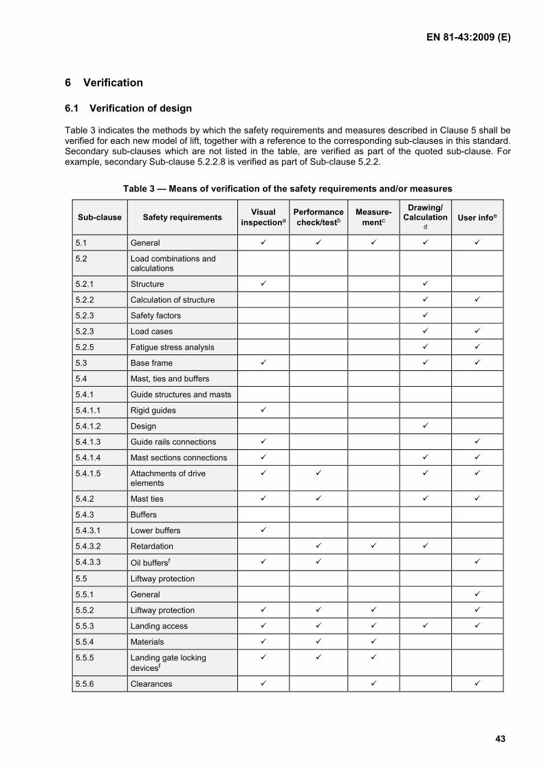
EN 81-43:2009 (E)
43
6 Verification
6.1 Verification of design
Table 3 indicates the methods by which the safety requirements and measures described in Clause 5 shall be verified for each new model of lift, together with a reference to the corresponding sub-clauses in this standard. Secondary sub-clauses which are not listed in the table, are verified as part of the quoted sub-clause. For example, secondary Sub-clause 5.2.2.8 is verified as part of Sub-clause 5.2.2.
Table 3 — Means of verification of the safety requirements and/or measures
Sub-clause Safety requirements Visual inspectiona
Performance check/testb
Measure-mentc
Drawing/ Calculation
d User infoe
5.1 General
5.2 Load combinations and calculations
5.2.1 Structure
5.2.2 Calculation of structure
5.2.3 Safety factors
5.2.3 Load cases
5.2.5 Fatigue stress analysis
5.3 Base frame
5.4 Mast, ties and buffers
5.4.1 Guide structures and masts
5.4.1.1 Rigid guides
5.4.1.2 Design
5.4.1.3 Guide rails connections
5.4.1.4 Mast sections connections
5.4.1.5 Attachments of drive elements
5.4.2 Mast ties
5.4.3 Buffers
5.4.3.1 Lower buffers
5.4.3.2 Retardation
5.4.3.3 Oil buffersf
5.5 Liftway protection
5.5.1 General
5.5.2 Liftway protection
5.5.3 Landing access
5.5.4 Materials
5.5.5 Landing gate locking devicesf
5.5.6 Clearances
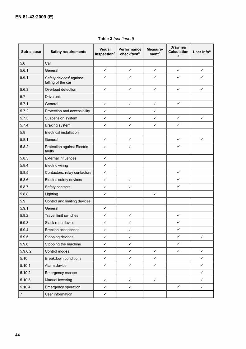
EN 81-43:2009 (E)
44
Table 3 (continued)
Sub-clause Safety requirements Visual inspectiona
Performance check/testb
Measure-mentc
Drawing/ Calculation
d User infoe
5.6 Car
5.6.1 General
5.6.1 Safety devicesf against falling of the car
5.6.3 Overload detection
5.7 Drive unit
5.7.1 General
5.7.2 Protection and accessibility
5.7.3 Suspension system
5.7.4 Braking system
5.8 Electrical installation
5.8.1 General
5.8.2 Protection against Electric faults
5.8.3 External influences
5.8.4 Electric wiring
5.8.5 Contactors, relay contactors
5.8.6 Electric safety devices
5.8.7 Safety contacts
5.8.8 Lighting
5.9 Control and limiting devices
5.9.1 General
5.9.2 Travel limit switches
5.9.3 Slack rope device
5.9.4 Erection accessories
5.9.5 Stopping devices
5.9.6 Stopping the machine
5.9.6.2 Control modes
5.10 Breakdown conditions
5.10.1 Alarm device
5.10.2 Emergency escape
5.10.3 Manual lowering
5.10.4 Emergency operation
7 User information

EN 81-43:2009 (E)
45
Table 3 (continued)
a Visual inspection will be used to verify the features necessary for the requirement by visual examination of the components supplied.
b A performance check/test will verify that the features provided perform their function in such a way that the requirement is met.
c Measurement will verify by the use of instruments that requirements are met, to specified limits.
d Drawings/calculations will verify that the design characteristics of the components provided meet the requirements.
e Verify that the relevant point is dealt with in the instruction handbook or by marking.
f See certain special verification tests required for some critical components, in Clause 6.2.
6.2 Special verification tests
6.2.1 Introduction
Special verification tests shall be carried out on the following components:
a) locking devices for landing and car gates;
b) overspeed safety device and overspeed governor;
c) energy accumulation type buffers with buffered return movement and energy dissipation buffers.
6.2.1.1 General
The precision of the instruments shall allow measurements to be made within the following tolerances:
a) ± 2 % masses, forces, distances, times, speeds;
b) ± 4 % accelerations, retardations;
c) ± 2 % voltages, currents;
d) ± 2°C temperatures.
6.2.1.2 Content of test report
The report shall at least contain the following information:
a) name of the testing facility;
b) test report number;
c) category, type and make or trade name;
d) manufacturer's name and address;
e) date of test;
f) documents according to 6.2.2.1.3;
g) place, date, name of person performing the test.
EN 81-43:2009 (E)
46
6.2.2 Locking devices for car and landing gates
6.2.2.1 General provisions
For permanent lifts EN 81-1:1998 applies. The following clauses are dealing with verification methods landing and car doors on temporary lifts.
6.2.2.1.1 Field of application
These procedures are applicable to locking devices for gates. It is understood that each component taking part in the locking of gates and in the checking of the locking forms part of the locking device.
6.2.2.1.2 Object of the test
The locking device shall be submitted to a test procedure to verify that insofar as construction and operation are concerned, it conforms to the requirements imposed by this standard.
6.2.2.1.3 Associated documents
The following documents shall be attached to the test report:
a) a schematic arrangement drawing with description of operation showing clearly all the details relating to the operation and the safety of the locking device, including the effective engagement of the locking elements and the point at which the electrical safety device operates and the operation of the emergency unlocking device;
b) information on the type of locking device including its rated voltage (AC and/or DC) and rated current.
6.2.2.1.4 Test samples
The test shall be carried out on a production model.
If the test of the locking device is only possible when the device is mounted in the corresponding gate (for example, sliding gates with several panels or hinged gates with several panels) the device shall be mounted on a complete gate in working order. However, the gate dimensions may be reduced by comparison with a production model, on condition that this does not falsify the test results.
6.2.2.2 Examinations and tests
6.2.2.2.1 Examination of operation
This test has the aim of verifying that the mechanical and electrical components of the locking device are operating correctly with respect to safety, and in conformity with the requirements of this standard.
In particular it shall be verified, that there is at least 7 mm engagement of the locking elements before the electric safety device operates (see Sub-clause 5.5.5.3.8).
6.2.2.2.2 Tests
These tests have the purpose of verifying the strength of the mechanical locking components and the electrical components.
The sample of the locking device in its normal operating position shall be controlled by the devices normally used to operate it.
EN 81-43:2009 (E)
47
The sample shall be lubricated in accordance with the normal requirements of the manufacturer of the locking device.
The number of complete cycles of operation shall be registered by mechanical or electrical counters.
6.2.2.2.2.1 Endurance test for temporary lifts
The locking device shall be submitted to min. 200 000 complete cycles (one cycle comprises one unlocking and one relocking operation).
The driving of the device shall be smooth, without shocks.
During the endurance test the electrical safety switch shall be mechanically operated by the lock as in normal operation and maintenance.
6.2.2.2.2.2 Static test
A test shall be made consisting of the application over a total period of 5 minutes of a static force of 1 kN.
This force shall be applied in the opening direction of the gate and in a position corresponding as far as possible to that which will be applied when a user attempts to open the gate.
6.2.2.2.2.3 Criteria for the tests
After the endurance test (6.2.2.2.2.1) and the static test (6.2.2.2.2.2) there shall not be any wear, deformation or breakage, which could adversely affect safety.
6.2.3 Overspeed safety device and overspeed governors
6.2.3.1 General provisions
The overspeed safety device and its compatible overspeed governor shall be tested in combination, using the suspension and guiding system employed in normal service.
The manufacturer shall state for what mass (kg) and rated speed (m/s) the test is to be carried out. If the overspeed safety device has to be certified for various masses and speeds then these shall be specified.
6.2.3.2 Method of test
6.2.3.2.1 Test for overspeed safety device for rack and pinion:
A representative combination of every new version of overspeed safety device and compatible overspeed governor shall be tested to apply stresses to all parts equivalent to those resulting from drop tests with the total permissible mass.
The tests shall be conducted at the governor tripping speed specified by the manufacturer.
The total number of repeated tests shall be not less than 30. At least there shall be:
a) 10 tests with rated load, drive engaged;
b) 5 tests with empty car, drive engaged;
c) 5 tests with 1,3 times rated load, drive engaged;
EN 81-43:2009 (E)
48
d) 5 tests with rated load, drive disengaged;
e) 5 tests with 1,3 times rated load, drive disengaged.
At the end of each one of these 5 sets of tests, the overspeed safety device shall be inspected and restored to its normal operating condition, with necessary adjustments and replacements.
6.2.3.2.2 Test for overspeed safety device gripping on ropes:
Relevant Clauses in EN 1808:1999, Annex B 1.4 applies and total number of tests shall not be less than 30. The tension in the rope shall be at least 100 N measured at the lowest point of the rope to prevent slack rope. After test performance the rope shall not have structural damages.
6.2.3.2.3 Test for overspeed safety device gripping guides:
EN 81-1:1998, Annex F3 and F4 applies.
6.2.3.3 Direct or indirect measurements shall be made of:
a) total height of the fall;
b) braking distance;
c) speed of tripping;
d) retardation as a function of time.
6.2.3.4 The following shall be checked:
a) that retardation conforms with 5.6.2.2;
b) that the maximum speed of tripping conforms to 5.6.2.9;
c) that there are no cracks or deformations;
d) in the case of a rope driven overspeed governor, that the tensile force in the rope conforms to 5.6.2.13.
6.2.3.5 Test report
The report shall indicate:
a) information according to 6.2.1.2;
b) type and application of the overspeed safety device and overspeed governor;
c) type(s) and model(s) of lift(s);
d) limits of the permissible total masses for the overspeed safety device incl. inertia effects;
e) limits of the tripping speed for the overspeed governor;
f) for overspeed safety devices operating on the guides, the permissible thickness of the guide blade, the minimum width of the gripping areas, the state of lubrication of the guides and their surface condition;
g) in the case of overspeed governors driven by rope, the diameter of the rope to be used, its construction, the tensile force on the rope which can be produced by the governor when tripped and, if a traction pulley is used, the minimum tensioning force.

EN 81-43:2009 (E)
49
6.2.4 Energy accumulation type buffers with buffered return movement and energy dissipation buffers
Special verification tests for these types of buffer shall be carried out according to the test procedures for type examination given in EN 81-1:1998, Sub-clause F5.
6.3 Verification tests on each lift before first use
Static and dynamic tests shall be performed to ensure that the lift has been correctly manufactured and assembled in order to check that all the devices provided are present and operating correctly. These tests may be carried out at the manufacturers premises or those of his authorised representative or at the place of use.
In particular it shall be verified:
a) proper function of all limit switches;
b) proper function of all controls;
c) function of the overspeed safety device within specified limits, both with empty car and with rated load in the car;
d) activation of overload detection device between 1,0 and 1,1 times rated load;
e) braking distance of brake system within specified limits;
f) proper function of gate locks;
g) dynamic test with 1,25 times rated load:
h) electrical tests as specified in EN 60204-32:2008.
7 User information
7.1 Instruction handbook
7.1.1 Comprehensive information
Each lift shall be accompanied by an instruction handbook, which shall be in accordance with Clause 6.5 of EN ISO 12100-2:2003.
7.1.2 Contents of the instruction handbook
The manufacturer and/or importer/supplier shall make available to the user an instruction handbook containing at the least, information about the following topics:
The contents of the instructions shall cover not only the intended use of the machinery but also take into account any reasonably foreseeable misuse thereof.
7.1.2.1 General information
a) manufacturers or suppliers name and address;
b) model designation;

EN 81-43:2009 (E)
50
c) range of serial numbers for which the instruction handbook is valid;
d) repeat of the safety marking and warning signs on the machine and their signification;
e) all compatible parts (mast sections, landing gates, ties, control systems, etc.) designed to be used in the lift installation.
7.1.2.2 Capacity and design information
a) working load;
b) rated speed;
c) maximum allowable freestanding height in and out of service;
d) maximum lifting height, untied mast;
e) maximum lifting height, tied mast;
f) tie distances;
g) top overhang of the mast;
h) maximum allowable horizontal and torsional deflection of the crane structure in service, out of service of the crane as well as under its emergency conditions;
i) maximum allowable acceleration and deceleration of the crane structure in service, out of service of the crane as well as under its emergency conditions;
j) maximum allowable wind speed during erection and dismantling;
k) maximum allowable wind speed in service;
l) maximum allowable wind speed out of service; design wind region (see Annex A, deviations due to local environment conditions may be possible!). Variations in mast tie intervals etc., shall be clearly indicated for the appropriate wind regions;
m) environmental restrictions as temperature range;
n) sound pressure level [dB(A)], measured at a distance of 1 m from the base enclosure and at a height of 1,60 m from the floor. The position and value of the maximum sound pressure shall be indicated.
Sufficient information shall be given in the instruction handbook such that the user can derive the particular details for each installation.
7.1.2.3 Dimensions and weights
a) internal size of car (length × width × height);
b) mast section: dimensions;
c) mast section: weight;
d) base unit (base frame, lowermost mast section(s), car and drive unit) dimensions and weight;
e) minimum area required for installation.

EN 81-43:2009 (E)
51
7.1.2.4 Electrical Power supply data
a) power – drive unit [kW];
b) supply voltage/frequency [V/Hz];
c) control voltage/frequency [V/Hz];
d) maximum starting current [A];
e) maximum power consumption [kW];
f) minimum power supply [kVA];
g) main power supply fuses and type [A];
h) outlets for portable tools – voltage and current [V, A].
7.1.2.5 Safety equipment
a) type of safety equipment (e.g. overspeed safety device, terminal and final stopping switches, landing gate switches);
b) additional safety equipment for erection, dismantling and maintenance;
c) emergency lowering arrangements.
7.1.2.6 Additional technical information
a) bolted mast joints (bolt diameter, bolt quality, tightening torque, criteria for replacement, possible restrictions regarding the use of prestressed high tensile bolts);
b) vertical load as a function of configuration of the lift;
c) tie arrangement and forces imposed on the supporting structure;
d) need for protection regarding hazardous areas around the lift;
e) information regarding any lifting points;
f) wire rope data;
g) consideration of the effects of any item which significantly increases the wind area;
h) consideration of any effects which significantly increases the wind speed e.g. adjacent tall buildings;
i) transport procedure to and from site.
7.1.2.7 Instructions for erection and dismantling
The instruction manual shall clearly indicate the various configurations foreseen by the manufacturer for erection and dismantling of the lift.
The instruction manual shall clearly indicate that different combinations of the lift and a crane are possible due to the fact that a great number of different types of cranes as well as configurations could be combined with one type of a lift.
EN 81-43:2009 (E)
52
It is important where any non-standard configurations are required, that the details of the interfaces between the lift and the crane shall be agreed between the manufacturer, the owner and the user, and information shall be added as addendum to the instruction handbook.
7.1.2.7.1 Clearances
7.1.2.7.1.1 Clearances around an installed lift
Any guarding attached to the crane at positions where contact with the lift is possible shall be in accordance with EN ISO 13857:2008.
7.1.2.7.1.2 Clearances around a lift installed on tower cranes under construction site conditions
a) If the safety distance between any point of access and any adjacent travelling part of the lift is less than 0,85 m (0,5 m if the rated speed is not more than 0,4 m/s) the liftway protection shall conform to EN ISO 13857:2008, Table 1 and be a minimum of 2,0 m high or extend the full height from floor to ceiling where this is less than 2 m.
b) If the safety distance is 0,85 m or more, a fixed protection (hand rail, intermediate rail and toeboard) to a minimum height of 1,1 m shall be provided. The clearance between the crane structure and any travelling part of the lift is not less than 0,75 m.
c) If the safety distance is 0,5 m or more and the rated speed is not more than 0,4 m/s and the car is only hold to run controlled from inside the car, a fixed protection (hand rail, intermediate rail and toeboard) to a minimum height of 1,1 m shall be provided. The clearance between the crane structure and any travelling part of the lift is not less than 0,4 m.
7.1.2.7.1.3 Clearances above and beneath the car
The instruction handbook shall include details of control measures to be introduced upon installation of the lift such that adequate clearances are maintained both above and beneath the car at its extreme position of travel. The construction parts (device) for ensuring the protective space are to be kept at the operating position, see 5.5.6.2.
7.1.2.7.2 Loads on supporting structure
Information shall be given so that the supporting structure for the lift installation can be suitably prepared in order that it shall withstand all resulting loads (forces as given in 5.2.2.4).
7.1.2.7.3 Erection and dismantling
The instruction handbook shall at least include the following:
a) competent persons shall erect and dismantle the lift;
b) connection of the lift to the electrical supply shall be made by a competent person in accordance with local regulations;
c) recommend the use of a Residual Current Device;
d) transportation to the site;
e) erection of mast sections and mast ties including information regarding the correct use of bolts (diameter, quality, tightening torque);
f) recommendations for lifting of heavy parts;

EN 81-43:2009 (E)
53
g) installation of, and safety requirements for base enclosure and landing gates, which shall be provided in the liftway protection at every point of access;
h) information about access between the lift and the crane; this access shall take place where a platform is located within the crane structure and the platform is fitted with adequate collective means against falling from a height;
i) illumination of landings (a statement shall be included to the effect that if the lift is to be used under poor lighting conditions then adequate site lighting shall be provided to illuminate the landings over the full height of travel of the lift);
j) test of the completed lift, which shall include the following minimum requirements:
1) identification of the lift;
2) functional tests of:
i. drive units and brakes;
ii. travel limits;
iii. car and landing gates;
iv. overload detection device;
v. clearances;
3) the lift shall be dynamically tested throughout the full range of travel with the rated load in the car as specified by the manufacturer;
4) the safety device against falling of the car shall be dynamically tested as specified by the manufacturer;
k) dismantling procedure.
7.1.2.8 Instructions for Operating and Usage
Detailed instructions shall be given regarding:
a) the safe operation and the minimum requirements for the training of operating personnel;
b) intended use;
c) operation of landing and car gates;
d) loading the car and possible restrictions regarding load position and concentration and securing of the load;
e) use of castors suitable for the possible gaps;
f) no loads on the car roof;
g) control of the lift, the function of any controls available to the user inside the car, at the base enclosure and the landings;
h) usage of the alarm device;
i) environmental conditions e.g. maximum in service wind speed.

EN 81-43:2009 (E)
54
7.1.2.9 Breakdown procedures
A separate section shall be included which provides all the information necessary for competent persons, regarding the handling of emergencies such as:
a) special controls;
b) safety devices, e.g. limit switches, overspeed safety device;
c) reacting to failures;
d) circuit diagram;
e) information about access (see 5.6.1.4.1.10 and 5.6.1.5).
7.1.2.10 Inspection and maintenance
The instruction handbook shall state the frequency of periodic examinations, tests and maintenance depending on manufacturers requirements, operating conditions and frequency of use. For maintenance work EN 13015:2001+A1:2008 may be used. Detailed information regarding the items to be checked and suitability for use shall be given.
Attention shall be drawn to observe national regulations.
The instruction handbook shall also state the contents of the logbook, if that is not delivered with the machinery.
It shall be stated which parts are subject to wear and the criteria for replacement, e.g. braking distances of motor brakes and overspeed safety devices, ISO 4309:2004 for replacement of steel wire ropes. The instruction handbook shall include a section dealing with thorough examination with regard to fatigue life (see also 5.2.5.1).
7.2 Markings
The manufacturer shall provide the following information on one or more durable labels fixed in a prominent place on the lift, in accordance with 6.4 of EN ISO 12100-2:2003.
7.2.1 Identification plate within the car
a) name and address of the manufacturer or his authorised representative;
b) type designation;
c) serial number;
d) CE-marking;
e) year of construction;
f) working load [kg]; maximum number of passengers
g) lifting height; applicable only for temporary installed lift
h) wire rope data, where applicable;
i) weight of base unit; applicable only for temporary installed lift
j) rated speed.
EN 81-43:2009 (E)
55
7.2.2 Mast or guide section identification
Each individual mast or guide section shall be marked with an identification or serial number enabling the date of manufacture to be determined.
7.2.3 Basic user information label
out of service position of the car; applicable only for lifts (temporary or permanent) outside installed and without shaft
observation of operating manual.
Additional information for lifts installed on tower cranes under construction site conditions:
a) mast height;
b) top overhang of mast;
c) bolted mast joints (bolt diameter, bolt quality, tightening torque);
d) power supply (residual current device);
e) safety clearances;
f) sketch of mast ties, with distances between ties.
7.2.4 Label in the car
working load and maximum number of passengers; minimum height of characters: 25 mm;
7.2.5 Label at ground level
access inside ground enclosure by authorised and competent personnel only.
7.2.6 Label at overspeed safety device
a) name and address of manufacturer;
b) number of type examination certificate;
c) tripping speed;
d) year of construction and serial number.
e) maximum braking mass [kg];
f) steel wire ropes specification for overspeed safety device(s) acting on ropes.

EN 81-43:2009 (E)
56
7.2.7 Drive motor label
a) name and address of manufacturer;
b) type designation;
c) year of construction and serial number.
7.3 Marking of control elements
All control elements have to be clearly marked. The use of pictograms is recommended.

EN 81-43:2009 (E)
57
Annex A (normative)
European stormwind map
Figure A.1 — European stormwind map

EN 81-43:2009 (E)
58
Annex B (normative)
Electric safety devices
Table B.1 — List of electric safety devices
Clause Devices checked
5.4.3.3 Oil Buffers
5.5.5.1 Closed position of landing gates
5.5.5.2 Closed position of landing gate locking devices
5.5.6.2 Moveable prop
5.6.1.4.1.6 Closed position of car gates
5.6.1.5 Locked position of trap door or escape door
5.6.2.3 Operation of overspeed safety devices
5.6.2.13 Operation of overspeed governor
5.9.2.2 Final limit switches
5.9.3 Slack rope in drive unit
5.9.4 Erection accessories
5.9.5 Stopping devices
5.9.7.2.1 Closed position of movable protection (car)
5.9.7.2.3 Inspection switch
5.10.4.3 Electrical emergency operation switch

EN 81-43:2009 (E)
59
Annex ZA (informative)
Relationship between this European Standard and the Essential
Requirements of EU Directive 98/37/EC
This European Standard has been prepared under a mandate given to CEN by the European Commission and the European Free Trade Association to provide one means of conforming to Essential Requirements of the New Approach Directive Machinery 98/37/EC amended by 98/79/EC.
Once this standard is cited in the Official Journal of the European Communities under that Directive and has been implemented as a national standard in at least one Member State, compliance with the normative clauses of this standard confers, within the limits of the scope of this standard, a presumption of conformity with the relevant Essential Requirements, except ESR 1.5.8 and 1.7.4 f), of that Directive and associated EFTA regulations.
WARNING — Other requirements and other EU Directives may be applicable to the product(s) falling within the scope of this standard.

EN 81-43:2009 (E)
60
Annex ZB (informative)
Relationship between this European Standard and the Essential
Requirements of EU Directive 2006/42/EC
This European Standard has been prepared under a mandate given to CEN by the European Commission and the European Free Trade Association to provide one means of conforming to Essential Requirements of the New Approach Directive Machinery 2006/42/EC.
Once this standard is cited in the Official Journal of the European Communities under that Directive and has been implemented as a national standard in at least one Member State, compliance with the normative clauses of this standard confers, within the limits of the scope of this standard, a presumption of conformity with the relevant Essential Requirements, except ESR 1.5.8 and 1.7.4.2 u), of that Directive and associated EFTA regulations.
WARNING — Other requirements and other EU Directives may be applicable to the product(s) falling within the scope of this standard.

EN 81-43:2009 (E)
61
Bibliography
[1] EN 13015:2001+A1:2008, Maintenance for lifts and escalators — Rules for maintenance instructions
[2] EN 12158-1:2000, Builders hoists for goods — Part 1: Hoists with accessible platforms
[3] EN 12158-2:2000, Builders hoists for goods — Part 2: Inclined hoists with non-accessible load carrying devices
[4] EN 14502-2:2005+A1:2008, Cranes — Equipment for the lifting of persons — Part 2: Elevating control stations