Embed Size (px)
Citation preview
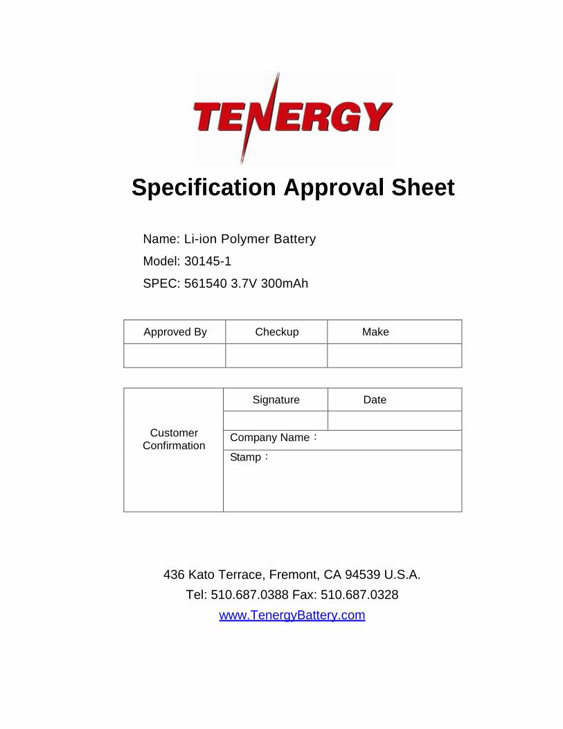
Specification Approval Sheet
Name: Li-ion Polymer Battery
Model: 30145-1
SPEC: 561540 3.7V 300mAh
Approved By Checkup Make
Customer Confirmation
Signature Date
Company Name:
Stamp:
436 Kato Terrace, Fremont, CA 94539 U.S.A.
Tel: 510.687.0388 Fax: 510.687.0328
www.TenergyBattery.com

Specifications and data are subject to change without notice. Contact Tenergy for latest information. ©2010 Tenergy Corporation. All rights reserved. Page 2 of 16
Tenergy Corporation 436 Kato Terrace
Fremont, CA 94539 Tel: 510.687.0388 Fax: 510.687.0328
www.TenergyBattery.com email: [email protected]
AMENDMENT RECORDS
Modification Time
Description
Issued Date
Approved By
0
New release
2012-6-15
Specifications and data are subject to change without notice. Contact Tenergy for latest information. ©2010 Tenergy Corporation. All rights reserved. Page 3 of 16
Tenergy Corporation 436 Kato Terrace
Fremont, CA 94539 Tel: 510.687.0388 Fax: 510.687.0328
www.TenergyBattery.com email: [email protected]
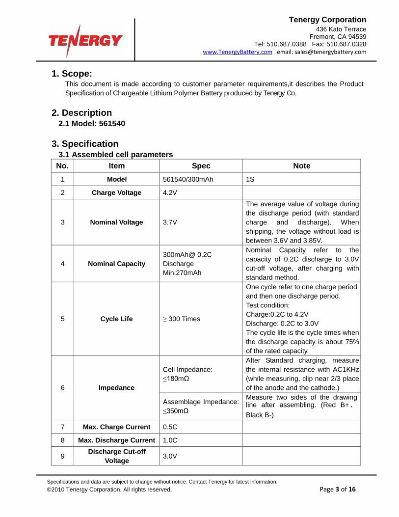
1. Scope: This document is made according to customer parameter requirements,it describes the Product Specification of Chargeable Lithium Polymer Battery produced by Tenergy Co.
2. Description
2.1 Model: 561540 3. Specification
3.1 Assembled cell parameters No. Item Spec Note
1 Model 561540/300mAh 1S
2 Charge Voltage 4.2V
3
Nominal Voltage
3.7V
The average value of voltage during the discharge period (with standard charge and discharge). When shipping, the voltage without load is between 3.6V and 3.85V.
4
Nominal Capacity
300mAh@ 0.2C Discharge Min:270mAh
Nominal Capacity refer to the capacity of 0.2C discharge to 3.0V cut-off voltage, after charging with standard method.
5
Cycle Life
≥ 300 Times
One cycle refer to one charge period and then one discharge period. Test condition: Charge:0.2C to 4.2V Discharge: 0.2C to 3.0V The cycle life is the cycle times when the discharge capacity is about 75% of the rated capacity.
6
Impedance
Cell Impedance: ≤180mΩ
After Standard charging, measure the internal resistance with AC1KHz (while measuring, clip near 2/3 place of the anode and the cathode.)
Assemblage Impedance: ≤350mΩ
Measure two sides of the drawing line after assembling. (Red B+ 、 Black B-)
7 Max. Charge Current 0.5C
8 Max. Discharge Current 1.0C
9 Discharge Cut-off Voltage
3.0V

Specifications and data are subject to change without notice. Contact Tenergy for latest information. ©2010 Tenergy Corporation. All rights reserved. Page 4 of 16
Tenergy Corporation 436 Kato Terrace
Fremont, CA 94539 Tel: 510.687.0388 Fax: 510.687.0328
www.TenergyBattery.com email: [email protected]
10
Operating Temperature
Discharge: -10~ +45 Charge: 0~ +45
Cells must be stored at 3.6V ~ 3.9V. Over long storage periods cells should be cycled every 90 days. The method is to do a charge-discharge cycle with standard method, then charge to 3.6V ~ 3.9V.
11
long term storage temperature
-5 ~+35 Relative humidity: 45~75%RH Voltage:3.8±0.1V
12 Cell Weight Approx: 6g
13 PCM YK-ML09FF(GM)
14
single cell Dimension
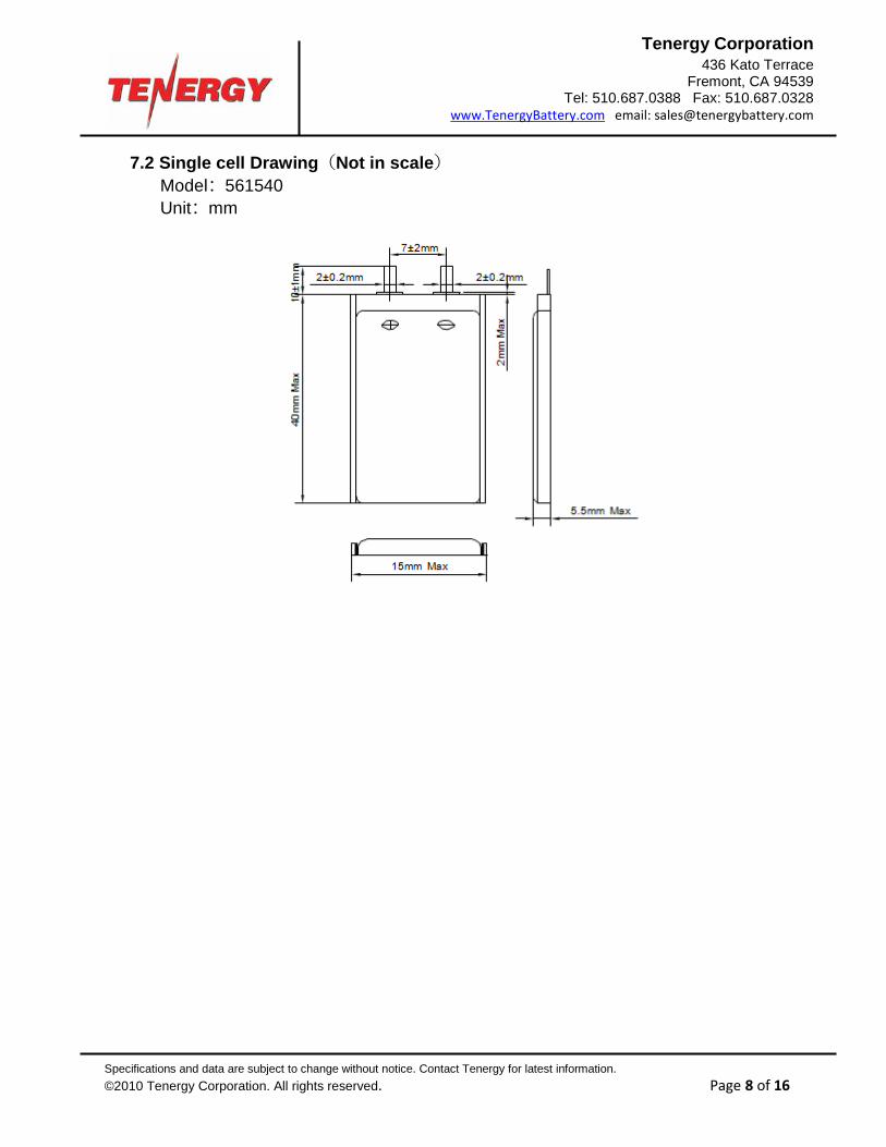
Length:40mm Max Width:15mm Max Thickness:5.5mm Max
Measured weight of 300gf at 25± 1. Not including Tabs
15
Assemblage Dimension
Length:41mm Max Width:15.5mm Max Thickness:5.6mm Max
Measured weight of 300gf at 25± 1.Not including battery drawing line.
4. Battery Cell Performance Criteria 4.1 Standard testing environment
Unless specifically stated otherwise, tests must be done within one month of delivery and the number of charging-recharging cycles is fewer than 5. The following is test conditions: Test conditions: Ambient Temperature: 25ºC ± 1ºC Ambient Humidity: 45~75%RH
4.2 The requirement of measure instrument (1) The measurement instrument has been certified by a qualified source. (2) The accuracy of the measuring instrument is less than 0.01mm. (3) The accuracy of multimeter is at least 0.5%. While measuring the voltage, the internal
resistance can not be less than 10KΩ. (4) The principle internal resistance is 1KHz LCR; the accuracy is 0.2%.
The internal resistance can vary based upon temperature and the charging mode. It is relevant to the PTC and the length and resistance of the wiring.
(5) The current accuracy of the battery test system is at least ±0.1%, isobarically accuracy is ±0.5%, and timer accuracy is not less than ±0.1%.
(6) The accuracy of the thermometer is at least ±0.5ºC. 4.3 Visual inspection
Not allowing any visual defects which will affect the electronic characteristics, such as leakage and damage.
4.4 Charge/Discharge Methods and Test Conditions

Specifications and data are subject to change without notice. Contact Tenergy for latest information. ©2010 Tenergy Corporation. All rights reserved. Page 5 of 16
Tenergy Corporation 436 Kato Terrace
Fremont, CA 94539 Tel: 510.687.0388 Fax: 510.687.0328
www.TenergyBattery.com email: [email protected]
No. Item Testing Conditions and Method
1 Charging Current
Standard CC:0.2C Quick CC:0.5C
2 Low-temperature
Charging (0~10)
Below 0.1C current charge from 3.0V to 4.2V, then CV to 0.05C cutoff, Then CV to 0.05C cutoff.
3 Standard Charging (0~45)
Constant Current Charging at 0.2C to 4.2V. Constant Voltage Charging at 4.2V to cut-off current≤0.05C.
4 Quick Charging (10~45)
Constant Current Charging at 0.5C to 4.2V. Constant Voltage Charging at 4.2V to cut-off current≤0.05C.
5 Standard Discharge
(-10~45)
Constant discharge at 0.2C to cut-off voltage of 3.0V.
6
Charging Time
Standard charging time :8 hours Quick charging time:2.8 hours
7
Temperature & Humidity
Low-temperature Charging: 0ºC~ 10ºC 45~75% RH Standard charging: 0ºC~ 45ºC 45~75% RH Quick charging: 10ºC~ 45ºC 45~75%RH Standard discharging: -10ºC~ 45 45~75% RH
8 Cell Voltage 3.6~3.85V (Before shipping)
4.5 Mechanical Characteristics
No. Item Testing Conditions and Method Standard
1
Vibration Test
After standard charging, the cell is secured to a vibration table and subjected to vibration cycling in which the frequency is varied at the rate of 1Hz per minute between 10Hz and 55Hz; the excursion of the vibration is 0.38mm. The cell shall be vibrated for 30 minutes on each of X, Y, and Z axis.
No explosion, no fire
2
Drop Test A charged battery is dropped from a height of
1 meter two times onto a concrete surface.
No explosion, no fire
4.6 Safety Test
No. Item Testing Conditions and Method Standard
1
Over-charge
After standard charging,the cell is conducted for 8 hours while the constant voltage is held at 4.5V and standard charging current flows through it.
No explosion, no fire
Specifications and data are subject to change without notice. Contact Tenergy for latest information. ©2010 Tenergy Corporation. All rights reserved. Page 6 of 16
Tenergy Corporation 436 Kato Terrace
Fremont, CA 94539 Tel: 510.687.0388 Fax: 510.687.0328
www.TenergyBattery.com email: [email protected]
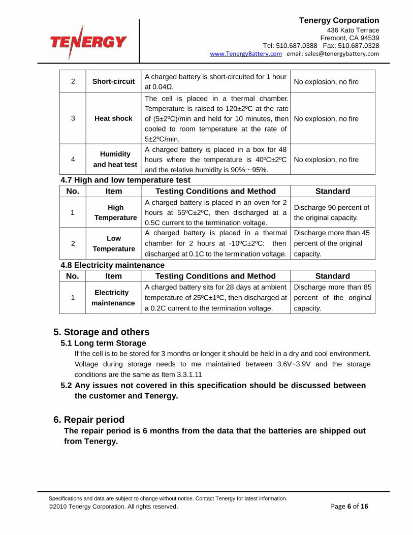
2
Short-circuit A charged battery is short-circuited for 1 hour
at 0.04Ω.
No explosion, no fire
3
Heat shock
The cell is placed in a thermal chamber. Temperature is raised to 120±2ºC at the rate of (5±2ºC)/min and held for 10 minutes, then cooled to room temperature at the rate of 5±2ºC/min.
No explosion, no fire
4
Humidity
and heat test
A charged battery is placed in a box for 48 hours where the temperature is 40ºC±2ºC and the relative humidity is 90%~95%.
No explosion, no fire
4.7 High and low temperature test
No. Item Testing Conditions and Method Standard
1
High
Temperature
A charged battery is placed in an oven for 2 hours at 55ºC±2ºC, then discharged at a 0.5C current to the termination voltage.
Discharge 90 percent of the original capacity.
2
Low
Temperature
A charged battery is placed in a thermal chamber for 2 hours at -10ºC±2ºC; then discharged at 0.1C to the termination voltage.
Discharge more than 45 percent of the original capacity.
4.8 Electricity maintenance
No. Item Testing Conditions and Method Standard
1
Electricity
maintenance
A charged battery sits for 28 days at ambient temperature of 25ºC±1ºC, then discharged at a 0.2C current to the termination voltage.
Discharge more than 85 percent of the original capacity.
5. Storage and others
5.1 Long term Storage If the cell is to be stored for 3 months or longer it should be held in a dry and cool environment. Voltage during storage needs to me maintained between 3.6V~3.9V and the storage conditions are the same as Item 3.3.1.11
5.2 Any issues not covered in this specification should be discussed between the customer and Tenergy.
6. Repair period
The repair period is 6 months from the data that the batteries are shipped out from Tenergy.
Specifications and data are subject to change without notice. Contact Tenergy for latest information. ©2010 Tenergy Corporation. All rights reserved. Page 7 of 16
Tenergy Corporation 436 Kato Terrace
Fremont, CA 94539 Tel: 510.687.0388 Fax: 510.687.0328
www.TenergyBattery.com email: [email protected]
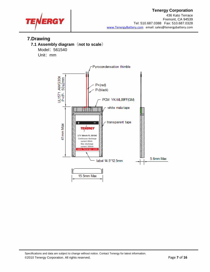
7.Drawing 7.1 Assembly diagram(not to scale)
Model:561540 Unit:mm
Specifications and data are subject to change without notice. Contact Tenergy for latest information. ©2010 Tenergy Corporation. All rights reserved. Page 8 of 16
Tenergy Corporation 436 Kato Terrace
Fremont, CA 94539 Tel: 510.687.0388 Fax: 510.687.0328
www.TenergyBattery.com email: [email protected]
7.2 Single cell Drawing(Not in scale) Model:561540 Unit:mm

Specifications and data are subject to change without notice. Contact Tenergy for latest information. ©2010 Tenergy Corporation. All rights reserved. Page 9 of 16
Tenergy Corporation 436 Kato Terrace
Fremont, CA 94539 Tel: 510.687.0388 Fax: 510.687.0328
www.TenergyBattery.com email: [email protected]
Handling Precaution and Guideline
For LIP (Lithium-Ion Polymer) Rechargeable batteries
Preface
This document of ‘Handling Precautions and Guidelines for LIPO Rechargeable Batteries’ shall be applied to the battery cells manufactured by Tenergy Co. Note (1): The customer is requested to contact TENERGY in advance if and when the customer needs variations of the operating conditions described in this document. Additional experimentation may be required to verify performance and safety under such conditions.
Note (2): TENERGY will take no responsibility for any accident when the cell is used under conditions outside of this specification. Note (3): TENERGY will inform the customer in writing of improvement(s) regarding proper use and handling of the cell if it is deemed necessary.
Tenergy reserves the right to revise this specification before the customer signs the datasheet. If a revision is required, TENERGY will notify the customer. 1. Charging 1.1 Charging Current: The charging current must be less than the maximum charge current specified in the Specification Approval Sheet. 1.2 Charging Voltage: The charging voltage must be less than the maximum nominal voltage 4.2V, and the charging voltage upper limit is 4.30V (single pack). 1.3 Charging Temperature: The cell must be charged within the range specified in this Specification Approval Sheet. 1.4 Notes: Since charging is done with a constant current or a constant voltage, reverse charging is prohibited. If the cell is connected improperly it cannot be charged. Reverse charging can damage the cell and lead to degradation of cell performance, impair cell safety, and cause heat generation or leakage. 2. Discharging Current:
Specifications and data are subject to change without notice. Contact Tenergy for latest information. ©2010 Tenergy Corporation. All rights reserved. Page 10 of 16
Tenergy Corporation 436 Kato Terrace
Fremont, CA 94539 Tel: 510.687.0388 Fax: 510.687.0328
www.TenergyBattery.com email: [email protected]
The cell shall be discharged at less than the maximum discharge current specified in the Specification Approval Sheet. A high discharging current may reduce the discharge capacity significantly or cause overheating. 3. Discharging Temperature The Discharging Temperature must be within the range specified in this Specification Approval Sheet. 4. Over-Discharge Over-discharging will cause cell degradation and functional losses. The cell can degrade into an over-discharge state through self discharging. In order to prevent over-discharging, the cell should be charged periodically to retain between 3.6V and 3.9V. 5. Protective Circuit Module 5.1 The cell/battery pack shall contain a PCM that can protect the cell/ battery pack properly. PCM shall have the following functions to ensure safety and prevent deterioration of cell performance: (1) overcharging prevention (2) over-discharging prevention (3) over current prevention. 5.2 Overcharging Protection Overcharging prevention stops charging if any cell of the battery pack reaches 4.30V. 5.3 Over-discharging protection The Over-discharging protection monitors the voltage of every cell in the pack and works to avoid a drop in the cell voltage to 2.8V or less. 6. Storage Cells should be stored at the proper temperature that is identified in the Specification Approval Sheet. 7. Notice 7.1 Handling of cells: Don’t charge the cells and keep them in a charged state for a long time.( Display units should dismantle the battery)
Specifications and data are subject to change without notice. Contact Tenergy for latest information. ©2010 Tenergy Corporation. All rights reserved. Page 11 of 16
Tenergy Corporation 436 Kato Terrace
Fremont, CA 94539 Tel: 510.687.0388 Fax: 510.687.0328
www.TenergyBattery.com email: [email protected]
Avoid any short-circuit. It will cause the leads to get hot and lose electronic functions. Soft package is easily damaged by sharp objects such as needles and knives. Avoid touching the cells with sharp objects when handling and storing. Next to the leads is the sealed edge. Don’t bend or fold the sealing edge as it is sensitive to movement. Don’t open the folded edge on the sides of the cell. Don’t bend the tabs as the tabs are sensitive. Avoid mechanical shock to the cells. Don’t put the cells into an oven, washing machine or any high-voltage container. Don’t use a charger without a safety certification. Use only a recommended charger. You should immediately stop charging if the cell overheats, emits an odor, changes color, changes shape, etc. Adults should supervise the use of batteries by children. Before using batteries, please carefully read and understand the handling guidelines. Avoid electro-static discharge when using, charging, and storing cells. Avoid putting the battery in contact with metal conductors such as neck chains, barrettes, or bolts, etc. Don’t use metal conductors to connect the positive and negative leads together. Avoid errors during assembly by contacting the positive lead with the negative lead. After full charge the battery,if the discharge time is less than 60% of normal discharge time , please immediately stop using and change it or contact with the customer service personnel to repair. 7.2 Notice for Designing Battery Pack 7.2.1 Package Design ① The battery pack should have sufficient strength and the battery should be protected from mechanical shock. ② No sharp objects should be inside the pack containing the battery. 7.2.2 PCM Design ① The overcharge threshold voltage should be less than 4.30V (single pack). ② The over-discharge threshold voltage should not be lower than 2.8V (single pack). ③ The PCM should have short circuit protection. 7.3 Notice for Assembling Battery Pack 7.3.1 Tab connection ① Ultrasonic welding or spot welding is recommended to connect the battery with

Specifications and data are subject to change without notice. Contact Tenergy for latest information. ©2010 Tenergy Corporation. All rights reserved. Page 12 of 16
Tenergy Corporation 436 Kato Terrace
Fremont, CA 94539 Tel: 510.687.0388 Fax: 510.687.0328
www.TenergyBattery.com email: [email protected]
the PCM or other parts. ② If the tab is to be soldered to the PCM, the instructions below are very important to ensure battery performance. a) The solder iron should be temperature controlled and ESD safe. b) Soldering temperature should not exceed 350±10. c) Soldering time should not be longer than 3 seconds. d) Soldering times should not be fewer than 5. e) Let the battery tab cool down before soldering again. f) Direct heat to the cell body is strictly prohibited. The battery will be damaged by heat above approx. 60ºC. 7.3.2 Cell fixing ① The cell should be fixed to the battery pack by its large surface area. ② There should be no sharp edges at the assembly contact area. ③ Cells must be held firmly in the battery pack; movement is not allowed. ④ The total thickness (the cell thickness plus the thickness of auxiliary materials,e.g. sponge pad, insulate pad, tape and so on) can't exceed the interior room of the plastic case, in order to prevent the cell from the damage and safe issue. 8. Others 8.1 Disassembly may cause an internal short circuit to the cell, which may cause out-gassing, fire, or other problems. 8.2 LIP battery should not have liquid flowing, but in case the electrolyte come into contact with the skin, or eyes, physicians, we recommend as below: a. The electrolyte touch eyes: Flush the electrolyte immediately with fresh water for 15min. and medical advice is to be sought. b. The electrolyte touch skin: Flush the electrolyte immediately with a great deal of fresh water. c. Breath the released gas: Go outside to breath flash air. d. Mis-eaten: Go to take some medical advice. 8.3 Prohibition of dumping of cells into fire Never incinerate or dispose the cells in fire, for these may cause firing of the cells. 8.4 The cells should never be soaked with liquids such as water, drinks or oil. 8.5 Prohibit using the cells mixed with different manufactories. Prohibit using new cells mixed with old ones. 8.6 Prohibit using damaged cells.

Specifications and data are subject to change without notice. Contact Tenergy for latest information. ©2010 Tenergy Corporation. All rights reserved. Page 13 of 16
Tenergy Corporation 436 Kato Terrace
Fremont, CA 94539 Tel: 510.687.0388 Fax: 510.687.0328
www.TenergyBattery.com email: [email protected]
9. Recommended Notice: 9.1 Using cells on specified facilities only. 9.2 Using cells in normal ambition temperature. Temperature: -10~35,Relative Humidity: 45~75%. 9.3 Using the cells, away from heat source. Don’t let children play with cells. Don’t drop cells. Charge cells with specified charger. 9.4 Avoid the positive pole shortcutting with the negative one. Avoid the cells affected with damp. 9.5 Useless cells should be deal with in a safety way. Don’t drop them into the water or fire. Special Notice: If the cell isn’t used for a long time, please keep the cells in a half-charged state neither fully charged and not completely discharged. Recharge the cells and use half of the power after 2-3 months. Store the cells in a cool and dry place. It will protect the cell from damage.
Specifications and data are subject to change without notice. Contact Tenergy for latest information. ©2010 Tenergy Corporation. All rights reserved. Page 14 of 16
Tenergy Corporation 436 Kato Terrace
Fremont, CA 94539 Tel: 510.687.0388 Fax: 510.687.0328
www.TenergyBattery.com email: [email protected]
Appendix
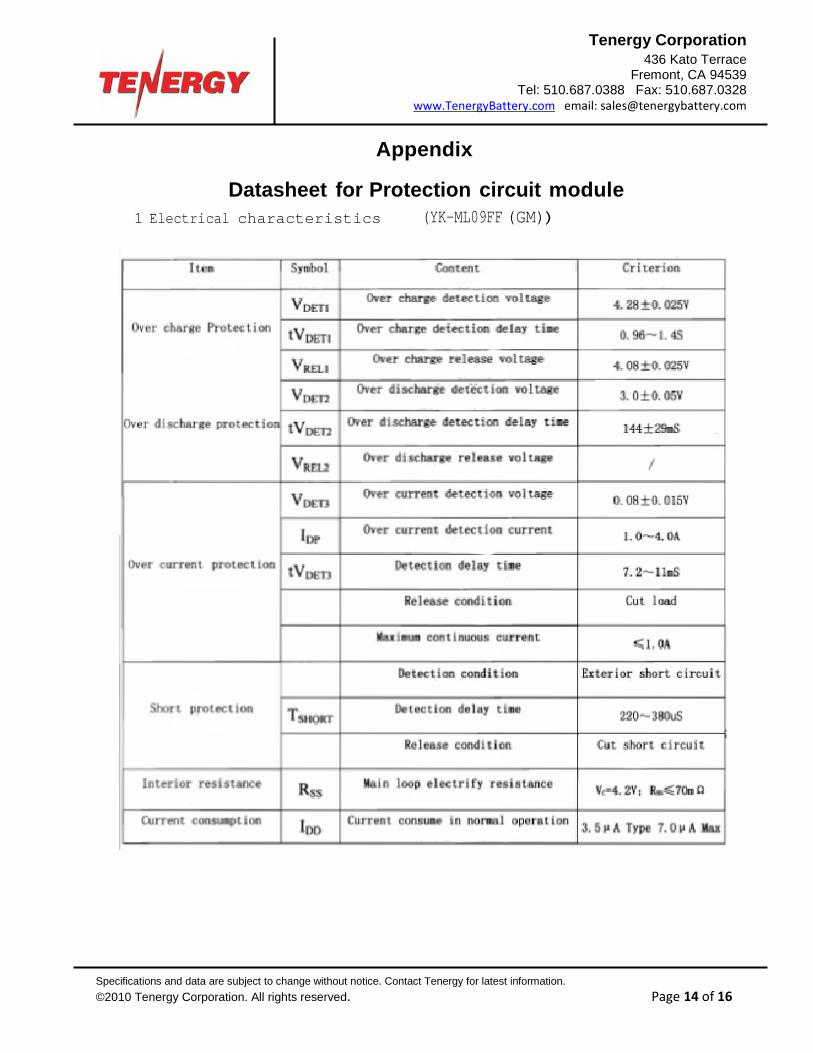
Datasheet for Protection circuit module 1 Electrical characteristics (YK-ML09FF (GM))

Specifications and data are subject to change without notice. Contact Tenergy for latest information. ©2010 Tenergy Corporation. All rights reserved. Page 15 of 16
Tenergy Corporation 436 Kato Terrace
Fremont, CA 94539 Tel: 510.687.0388 Fax: 510.687.0328
www.TenergyBattery.com email: [email protected]
2 Parts list
3 Application Circuit
4 PCB layout
Specifications and data are subject to change without notice. Contact Tenergy for latest information. ©2010 Tenergy Corporation. All rights reserved. Page 16 of 16
Tenergy Corporation 436 Kato Terrace
Fremont, CA 94539 Tel: 510.687.0388 Fax: 510.687.0328
www.TenergyBattery.com email: [email protected]
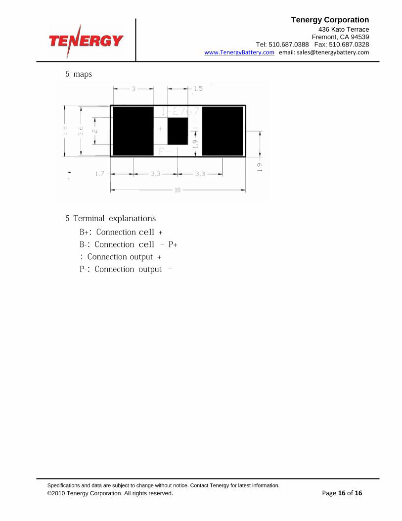
5 maps
5 Terminal explanations
B+:Connection cell +
B-:Connection cell – P+:Connection output +
P-:Connection output –