Embed Size (px)
Citation preview
NetLink Telephony Gateway SpectraLink Radio Protocol (SRP)
Installation, Setup, and Administration
Part Number: 72-0065-02 Issue N
SpectraLink Corporation Installation, Setup, and Administration NetLink Telephony Gateway
P
NOTICE SpectraLink Corporation has prepared this document for use by SpectraLink personnel and clients. The drawings and specifications contained herein are the property of SpectraLink and shall be neither reproduced in whole or in part without the prior written approval of SpectraLink, nor be implied to grant any license to make, use, or sell equipment manufactured in accordance herewith.
SpectraLink reserves the right to make changes in specifications and other information contained in this document without prior notice, and the reader should in all cases consult SpectraLink to determine whether any such changes have been made.
The terms and conditions governing the sale of SpectraLink hardware products and the licensing of SpectraLink software consist solely of those set forth in the written contracts between SpectraLink and its customers. No representation or other affirmation of fact contained in this document including but not limited to statements regarding capacity, response-time performance, suitability for use, or performance of products described herein shall be deemed to be a warranty by SpectraLink for any purpose, or give rise to any liability of SpectraLink whatsoever.
In no event shall SpectraLink be liable for any incidental, indirect, special, or consequential damages whatsoever (including but not limited to lost profits) arising out of or related to this document, or the information contained in it, even if SpectraLink has been advised, knew, or should have known of the possibility of such damages.
Trademark Information SpectraLink LinkPlus Link Wireless Telephone System NetLink Telephony Gateway NetLink Wireless Telephone NetLink SVP Server SpectraLink Voice Priority ccLink Wireless Telephone System NetLink e340 Wireless Telephone NetLink h340 Wireless Telephone NetLink i640 Wireless Telephone are trademarks and registered trademarks of SpectraLink Corporation. All other trademarks used herein are the property of their respective owners.
C
ISmwpet
SpectraLink Corporation 5755 Central Avenue Boulder, CO 80301 Within the United States, dial 303.440.5330 or toll free 800.676.5465 Outside the U.S., dial +1.303.440.5330 www.spectralink.com
art Number: 72-0065-02-N.doc Page 2
opyright © 1998 through 2005 SpectraLink Corporation. All rights reserved.
nformation in this document is subject to change without notice and does not represent a commitment on the part of pectraLink Corporation. The software described in this document is furnished under a license and/or copyright and ay only be used with the terms of SpectraLink’s software license agreement as found in this manual or at ww.spectralink.com/software.htm. The software may be used only in accordance with the terms of the agreement. No art of this manual, or the software described herein, may be reproduced or transmitted in any form or by any means, lectronic or mechanical, including photocopying and recording, for any purpose except for the sole intent to operate he product or without the express written permission of SpectraLink Corporation.
SpectraLink Corporation Installation, Setup, and Administration NetLink Telephony Gateway
Part Number: 72-0065-02-N.doc Page 3
Note concerning the NetLink Telephony Gateway: This equipment has been tested and found to comply with the limits for a Class A digital device, pursuant to Part 15 of the FCC Rules. These limits are designed to provide reasonable protection against harmful interference when the equipment is operated in a commercial environment. This equipment generates, uses, and can radiate radio frequency energy and, if not installed and used in accordance with the instruction manual, may cause harmful interference to radio communications. Operation of this equipment in a residential area is likely to cause harmful interference in which case the user will be required to correct the interference at his own expense.
Note concerning shielded cable: SpectraLink recommends the use of shielded cable for all external signal connections in order to maintain FCC Part 15 emissions requirements.
Note concerning the Wireless Telephones: This device complies with Part 15 of the FCC Rules. Operation is subject to the following two conditions: (1) This device may not cause harmful interference, and (2) this device must accept any interference received, including interference that may cause undesired operation.
WARNING Changes or modifications to this equipment not approved by SpectraLink Corporation may cause this equipment to not comply with part 15 of the FCC rules and void the user’s authority to operate this equipment.
WARNING SpectraLink products contain no user-serviceable parts inside. Refer servicing to qualified service personnel.
Important Safety Information Follow these general precautions while installing telephone equipment: Never install telephone wiring during a lightning storm.
Never install telephone jacks in wet locations unless the jack is specifically designed for wet locations.
Never touch uninsulated telephone wires or terminals unless the telephone line has been disconnected at the network interface.
Use caution when installing or modifying telephone lines.
SpectraLink Corporation Installation, Setup, and Administration NetLink Telephony Gateway
Part Number: 72-0065-02-N.doc Page 4
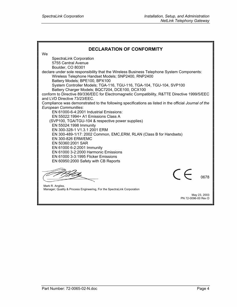
DECLARATION OF CONFORMITY We SpectraLink Corporation 5755 Central Avenue Boulder, CO 80301 declare under sole responsibility that the Wireless Business Telephone System Components: Wireless Telephone Handset Models; SNP2400, RNP2400 Battery Models; BPE100, BPX100 System Controller Models; TGA-116, TGU-116, TGA-104, TGU-104, SVP100 Battery Charger Models; BQC7204, DCE100, DCX100 conform to Directive 89/336/EEC for Electromagnetic Compatibility, R&TTE Directive 1999/5/EEC and LVD Directive 73/23/EEC. Compliance was demonstrated to the following specifications as listed in the official Journal of the European Communities: EN 61000-6-4:2001 Industrial Emissions: EN 55022:1994+ A1 Emissions Class A (SVP100, TGA/TGU-104 & respective power supplies) EN 55024:1998 Immunity EN 300-328-1 V1.3.1 2001 ERM EN 300-489-1/17: 2002 Common, EMC,ERM, RLAN (Class B for Handsets) EN 300-826 ERM/EMC EN 50360:2001 SAR EN 61000 6-2:2001 Immunity EN 61000 3-2:2000 Harmonic Emissions EN 61000 3-3:1995 Flicker Emissions EN 60950:2000 Safety with CB Reports
Mark R. Angliss, Manager; Quality & Process Engineering, For the SpectraLink Corporation
May 23, 2003 PN 72-0096-00 Rev D
0678
SpectraLink Corporation Installation, Setup, and Administration NetLink Telephony Gateway
Part Number: 72-0065-02-N.doc Page 5
FCC Information The NetLink 150 Telephony Gateway complies with Part 68, FCC Rules FCC Registration Number IYGUSA-33816-PX-E Ringer Equivalence 0.3B SpectraLink Corporation NetLink WTS Made in the USA This equipment complies with Part 68 of the FCC Rules. On the back of this equipment is a label that contains, among other information, the FCC Registration Number and Ringer Equivalence Number (REN) for this equipment. If requested, this information must be given to the telephone company. This equipment uses RJ-21 connectors. The REN is useful to determine the quantity of devices you may connect to your telephone line and still have all of those devices ring when your number is called. In most, but not all, areas, the sum of the RENs of all devices connected to one line should not exceed five (5.0). To be certain of the number of devices you may connect to your line, as determined by the REN, you should contact your local telephone company to determine the maximum REN for your calling area. If your telephone equipment causes harm to the telephone network, the telephone service may discontinue your service temporarily. If possible, they will notify you in advance. But if advance notice isn’t practical, you will be notified as soon as possible. You will be informed of your right to file a complaint with the FCC. Your telephone company may make changes in its facilities, equipment, operations or procedures that could affect the proper functioning of your equipment. If they do, you will be notified in advance to give you an opportunity to maintain uninterrupted telephone service. If you experience trouble with this telephone equipment, please contact: SpectraLink Corporation 5755 Central Avenue Boulder, CO 80301 303-440-5330 for information on obtaining service or repairs. The telephone company may ask that you disconnect this equipment from the network until the problem has been corrected or until you are sure that the equipment is not malfunctioning. There are no user serviceable parts in this equipment. This equipment may not be used on coin service provided by the telephone company. Connection to party lines is subject to state tariffs.
SpectraLink Corporation Installation, Setup, and Administration NetLink Telephony Gateway
Part Number: 72-0065-02-N.doc Page 6
Industry Canada (IC) Notice
Notice: The Industry Canada (IC) label identifies certified equipment. This certification means that the equipment meets telecommunications network protective, operational, and safety requirements as prescribed in the appropriate Terminal Equipment Technical Requirements document(s). The department does not guarantee the equipment will operate to the user’s satisfaction. Before installing this equipment, users should ensure that it is permissible to be connected to the facilities of the local telecommunications company. The equipment must also be installed using an acceptable method of connection. The customer should be aware that compliance with the above conditions may not prevent degradation of service in some situations. Repairs to certified equipment should be coordinated by a representative designated by the supplier. Any repairs or alterations made by a user to this equipment, or equipment malfunctions, may give the telecommunications company cause to request the user to disconnect the equipment. Users should ensure for their own protection that the electrical ground connections of the power utility, telephone lines and internal metallic water pipe system, if present, are connected together. This precaution may be particularly important in rural areas. Caution: Users should not attempt to make such connections themselves, but should contact the appropriate electric inspection authority, or electrician, as appropriate. Notice: The Ringer Equivalence Number (REN) assigned to each terminal device provides as indication of the maximum number of terminals allowed to be connected to a telephone interface. The termination of an interface may consist of any combination of devices. REN 0.3B Approval Numbers: 2128-9760 A
Warranty and Repair Service Center:
SpectraLink Corporation 5755 Central Avenue Boulder, CO 80301 303-440-5330
DOC Spread Spectrum certification Wireless Telephone Cert. No. 2128-K1374
SpectraLink Corporation Installation, Setup, and Administration NetLink Telephony Gateway
Part Number: 72-0065-02-N.doc Page 7
Table of Contents 1. ABOUT THIS DOCUMENT 9
1.1. Customer Support Hotline 9 1.2. Icons and Conventions 9
2. NETLINK OVERVIEW 10 2.1. System Architecture 10 2.2. Designing a System for Maximum Speed 11 2.3. System Components 13 2.4. The Front Panel of the NetLink Telephony Gateway 15
3. INSTALLATION AND CONFIGURATION STEPS 16
4. SITE PREPARATION 17 4.1. Required Materials 17 4.2. LAN Requirements 17 4.3. Location of NetLink Telephony Gateway and NetLink SVP Server 18
5. TELEPHONE INTERFACE CONFIGURATION 19 5.1. Prepare Demarcation (Demarc) Blocks 19 5.2. Install Telephone Demarc Blocks 19 5.3. Assign and Program Telephone Ports 19 5.4. Connect Telephone Lines to Demarc Blocks 20
6. PRE-INSTALLATION VERIFICATION 24 6.1. Verify Pre-Installation Requirements 24 6.2. Check Components 24
7. INSTALL NETLINK TELEPHONY GATEWAY 26
8. NETLINK TELEPHONY GATEWAY ADMINISTRATION OVERVIEW 30 8.1. NetLink Telephony Gateway Configuration Sequence 31 8.2. Send All 32 8.3. Navigating through the Administration Console Screens 33
9. CONNECTING TO THE NETLINK TELEPHONY GATEWAY 34 9.1. Connect via the Serial Port 34 9.2. Connecting Via Telnet 36 9.3. Connecting Via External Modem 36 9.4. Connecting via Internal Modem 38 9.5. Select a NetLink Telephony Gateway to Administer 38
10. MAIN MENU 39
11. NETWORK CONFIGURATION 40
12. SET OR CHANGE PASSWORD 43
13. NETLINK TELEPHONY GATEWAY CONFIGURATION 44 13.1. Resetting the NetLink Telephony Gateway 47
SpectraLink Corporation Installation, Setup, and Administration NetLink Telephony Gateway
Part Number: 72-0065-02-N.doc Page 8
14. TELEPHONE LINE CONFIGURATION 48 14.1. Adding or Changing a Wireless Telephone 48 14.2. Deleting a Wireless Telephone 50
15. FEATURES PROGRAMMING MENU 51
16. FEATURE PROGRAMMING (NO SOFTKEYS) 52 16.1. Programming Digital PBX Features 53 16.2. Programming Analog PBX Features 54 16.3. Programming the ADMIN Feature 55
17. MENU PROGRAMMING (NO SOFTKEYS) 56
18. SOFTKEY AND SHORTCUT KEY PROGRAMMING 58
19. NETLINK DOCKING STATION FEATURE KEYS PROGRAMMING 62
20. SOFTWARE MAINTENANCE 64 20.1. Software Updates 64 20.2. Upgrading Wireless Telephones 66 20.3. Backup and Restore NetLink Telephony Gateway Configuration 68
21. TROUBLESHOOTING VIA THE SYSTEM STATUS MENU 69 21.1. Access Point Status 71 21.2. Error Status 73 21.3. Network Status 78 21.4. Telephone Line Status 80 21.5. Wireless Telephone Status 82 21.6. Software Version 84
22. WIRELESS DEVICE PLANNING WORKSHEET 85
SpectraLink Corporation Installation, Setup, and Administration NetLink Telephony Gateway
Part Number: 72-0065-02-N.doc Page 9
1. About This Document This document explains how to install, configure, maintain and troubleshoot the NetLink Telephony Gateway.
The NetLink Telephony Gateway provides telephone functionality to NetLink Wireless Telephones and NetLink Docking Stations over a wireless local area network (LAN). The installation process connects the Gateway to an existing host telephone system and LAN. The configuration process covers downloading current software, setting network parameters, setting Gateway parameters, assigning Wireless Telephones to the lines controlled by the Gateway, and establishing feature programming. Maintenance covers adding and deleting Wireless Telephones, upgrading software, etc. The troubleshooting section provides directions for analyzing system functioning via the System Status menu.
1.1. Customer Support Hotline SpectraLink wants you to have a successful installation. If you have questions please contact our Customer Support Hotline at (800) 775-5330. The Hotline is open Monday through Friday, 5:00 AM to 7:00 PM Mountain Time.
1.2. Icons and Conventions This manual uses the following icons and conventions.
Caution! Follow these instructions carefully to avoid danger.
Note these instructions carefully.
NORM This typeface indicates a key, label, or button on the NetLink Telephony Gateway.
SpectraLink Corporation Installation, Setup, and Administration NetLink Telephony Gateway
Part Number: 72-0065-02-N.doc Page 10
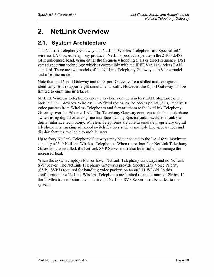
2. NetLink Overview 2.1. System Architecture The NetLink Telephony Gateway and NetLink Wireless Telephone are SpectraLink's wireless LAN-based telephony products. NetLink products operate in the 2.400-2.483 GHz unlicensed band, using either the frequency hopping (FH) or direct sequence (DS) spread spectrum technology which is compatible with the IEEE 802.11 wireless LAN standard. There are two models of the NetLink Telephony Gateway – an 8-line model and a 16-line model.
Note that the 16-port Gateway and the 8-port Gateway are installed and configured identically. Both support eight simultaneous calls. However, the 8-port Gateway will be limited to eight line interfaces.
NetLink Wireless Telephones operate as clients on the wireless LAN, alongside other mobile 802.11 devices. Wireless LAN fixed radios, called access points (APs), receive IP voice packets from Wireless Telephones and forward them to the NetLink Telephony Gateway over the Ethernet LAN. The Telephony Gateway connects to the host telephone switch using digital or analog line interfaces. Using SpectraLink’s exclusive LinkPlus digital interface technology, Wireless Telephones are able to emulate proprietary digital telephone sets, making advanced switch features such as multiple line appearances and display features available to mobile users.
Up to forty NetLink Telephony Gateways may be connected to the LAN for a maximum capacity of 640 NetLink Wireless Telephones. When more than four NetLink Telephony Gateways are installed, the NetLink SVP Server must also be installed to manage the increased load.
When the system employs four or fewer NetLink Telephony Gateways and no NetLink SVP Server, The NetLink Telephony Gateways provide SpectraLink Voice Priority (SVP). SVP is required for handling voice packets on an 802.11 WLAN. In this configuration the NetLink Wireless Telephones are limited to a maximum of 2Mb/s. If the 11Mb/s transmission rate is desired, a NetLink SVP Server must be added to the system.
SpectraLink Corporation Installation, Setup, and Administration NetLink Telephony Gateway
Part Number: 72-0065-02-N.doc Page 11
2.2. Designing a System for Maximum Speed The NetLink Telephony Gateway system is designed to support up to 40 Gateways in a single system. If the system has four or fewer Gateways, then the timing for the system is done through the IPC cables between each Gateway. If there are more than four Gateways in the system, then a NetLink SVP Server must be installed to handle the increased load and additional timing.
When using a system with fewer than four Gateways, the data rates that the Wireless Telephones can operate at are limited to 1 and 2 Mb/s. By adding a NetLink SVP Server into the system the phones will operate at data rates up to 11Mb/s. The IPC cables are not needed when the SVP Server is installed.
In a system with more than four Gateways installed, the SVP Server is required so the Wireless Telephones can operate at data rates up to 11Mb/s.
If you are deploying a SpectraLink NetLink Gateway system into an environment where you want to utilize data rates up to 11Mb/s, then you must have a NetLink SVP Server installed. This is true for any number of NetLink Telephony Gateways installed.
If you have your wireless network set up to run at a data rate of above 2Mb/s and you do not have an SVP Server, then the Wireless Telephones will not associate with the access points (APs) and will not operate. You must set up the 1 and 2 Mb/s data rates in the AP if the SVP Server is not installed.
If your wireless network is set up to allow data rates from 1 up to 11Mb/s and you do not have a NetLink SVP Server installed, the Wireless Telephones will default to using 1 and 2 Mb/s data rates. The data clients that are setup to use up to 11Mb/s will continue to utilize those higher data rates while the Wireless Telephones will be limited to 2Mb/s. In this case, depending on the wireless LAN design, the maximum number of Wireless Telephones per AP may be reduced if the wireless LAN was planned for higher data rates. See the Configuration Note for your APs for additional information.
SpectraLink Corporation Installation, Setup, and Administration NetLink Telephony Gateway
Part Number: 72-0065-02-N.doc Page 12
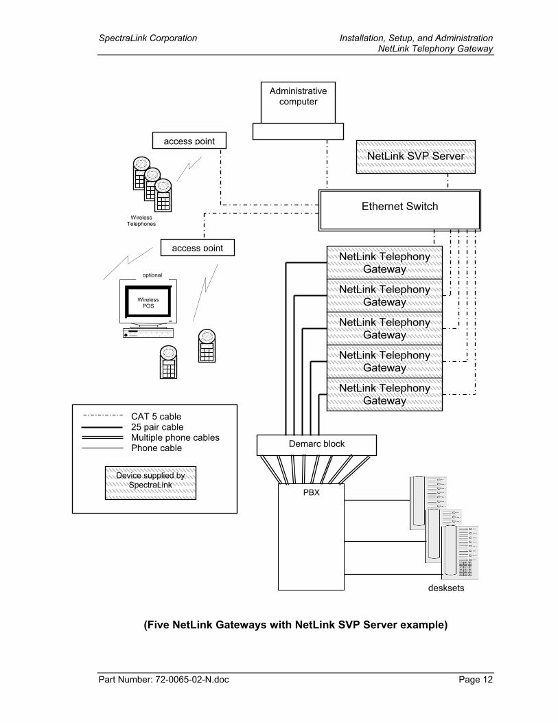
(Five NetLink Gateways with NetLink SVP Server example)
NetLink SVP Server
Ethernet Switch
access point
Wireless POS
Wireless Telephones
access point
desksets
optional
PBX
NetLink Telephony Gateway
NetLink Telephony Gateway
NetLink Telephony Gateway
NetLink Telephony Gateway
NetLink Telephony Gateway
Device supplied by SpectraLink
CAT 5 cable 25 pair cable Multiple phone cables Phone cable
Administrative computer
Demarc block
SpectraLink Corporation Installation, Setup, and Administration NetLink Telephony Gateway
Part Number: 72-0065-02-N.doc Page 13
2.3. System Components • NetLink Wireless Telephones – Employees can carry Wireless Telephones to place
and receive calls as they move throughout the building. The Wireless Telephones are to be used on-premises; they are not cellular or satellite phones. They are connected to the facility's existing telephone system and to the NetLink Telephony Gateway. Just like wired telephones, they can receive calls directly, receive transferred calls, transfer calls to other extensions, and make outside and long distance calls (subject to the restrictions applied in your facility.) NetLink Wireless Telephones can operate up to 11 Mb/s in a DSSS (Direct Sequence Spread Spectrum) system when a NetLink SVP Server is employed.
• NetLink Telephony Gateway – serves as the connecting point, or gateway, between the LAN and the existing telephone system. One or more NetLink Telephony Gateways are typically installed in the telephone equipment room. Each NetLink Telephony Gateway supports up to 16 telephone lines and Wireless Telephones. Up to 40 NetLink Telephony Gateways can be connected to the LAN to support additional telephone lines. If five or more NetLink Telephony Gateways are connected to the LAN, a NetLink SVP Server must be installed to handle the increased call volume.
SpectraLink offers digital NetLink Telephony Gateways that work with the digital ports on most common brands of telephone systems (PBX or key systems). We also offer an analog NetLink Telephony Gateway that works with telephone systems (CO, PBX, or Key Systems) with analog (loop start) ports.
• Access Points – supplied by third party vendors, access points (APs) provide the connection between the wired Ethernet LAN and the wireless (802.11) LAN. Access points must be positioned in all areas where NetLink Wireless Telephones will be used. The number and placement of access points will affect the coverage area and capacity of the wireless system. Typically, the requirements for use of NetLink Wireless Telephones are similar to that of wireless data devices. Contact SpectraLink, or a certified SpectraLink distributor, for specific information about your facility’s needs.
The NetLink system must connect to access points that utilize SpectraLink Voice Priority (SVP). Contact SpectraLink, or a certified SpectraLink distributor, to verify that your AP and its software version are supported.
• Ethernet Switch – a component in the wired Ethernet LAN infrastructure. Switches interconnect multiple network devices, including access points and NetLink Telephony Gateways. Ethernet switches are required to provide the higher performance network connections needed to handle combined voice and data traffic.
• Router – an optional component in the wired Ethernet LAN infrastructure that separates a wired LAN into segments so that network traffic is restricted to those segments that are directly involved in the communication. Installation of a network router is recommended in larger networks, where there may be significant network traffic not related to the wireless LAN. A router will isolate the wireless LAN from the associated wired LAN so that they are not impacted by each other’s traffic. The
SpectraLink Corporation Installation, Setup, and Administration NetLink Telephony Gateway
Part Number: 72-0065-02-N.doc Page 14
NetLink Telephony Gateways, the APs, and their associated Ethernet switch must all be on the same subnet because certain network traffic, such as required multicast events, will not be passed through a router.
• NetLink SVP Server – the NetLink SVP Server manages call volume and speed. It is a required component to utilize the 11Mb/s maximum transmission speed available in the NetLink Wireless Telephone. It is required in any system when five or more NetLink Telephony Gateways are connected to the LAN. With 40 NetLink Telephony Gateways cabled together, the NetLink SVP Server supports a maximum of 640 telephone lines and 120 simultaneous Wireless Telephone calls.
• SpectraLink Voice Priority (SVP) – the SpectraLink Quality of Service (QoS) mechanism that is implemented in the Wireless Telephone and AP to enhance voice quality over the wireless network. SVP gives preference to voice packets over data packets on the wireless medium, increasing the probability that all voice packets are transmitted efficiently and with minimum or no delay. SVP is fully compliant with the IEEE 802.11 and 802.11b standards.
• Administrative computer – Required for setup and maintenance of the NetLink Telephony Gateway and the NetLink SVP Server. This computer may be only temporarily connected to the Ethernet switch; a dedicated computer is not required. Some installations use a laptop to configure and maintain system components. The administrative computer can also be used to periodically upgrade the NetLink Telephony Gateway software via FTP and the Wireless Telephone and SVP Server software via TFTP.
SpectraLink Corporation Installation, Setup, and Administration NetLink Telephony Gateway
Part Number: 72-0065-02-N.doc Page 15
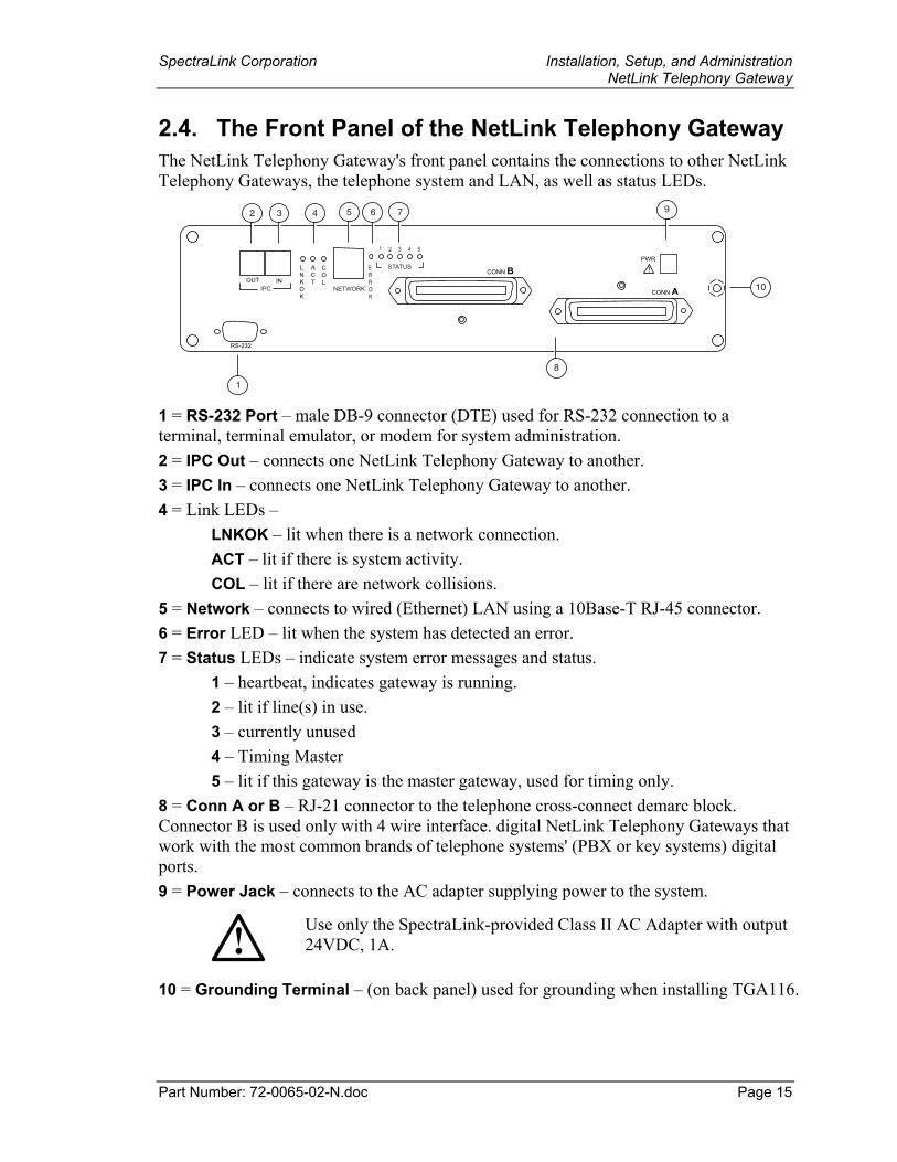
2.4. The Front Panel of the NetLink Telephony Gateway The NetLink Telephony Gateway's front panel contains the connections to other NetLink Telephony Gateways, the telephone system and LAN, as well as status LEDs.
PWR
CONN B
CONN A
ERROR
1 2 3 4 5
STATUS !
RS-232
LNKOK
ACT
COL
IPC NETWORKOUT IN
9
10
8
765432
1 1 = RS-232 Port – male DB-9 connector (DTE) used for RS-232 connection to a terminal, terminal emulator, or modem for system administration. 2 = IPC Out – connects one NetLink Telephony Gateway to another. 3 = IPC In – connects one NetLink Telephony Gateway to another. 4 = Link LEDs –
LNKOK – lit when there is a network connection. ACT – lit if there is system activity. COL – lit if there are network collisions.
5 = Network – connects to wired (Ethernet) LAN using a 10Base-T RJ-45 connector. 6 = Error LED – lit when the system has detected an error. 7 = Status LEDs – indicate system error messages and status.
1 – heartbeat, indicates gateway is running. 2 – lit if line(s) in use. 3 – currently unused 4 – Timing Master 5 – lit if this gateway is the master gateway, used for timing only.
8 = Conn A or B – RJ-21 connector to the telephone cross-connect demarc block. Connector B is used only with 4 wire interface. digital NetLink Telephony Gateways that work with the most common brands of telephone systems' (PBX or key systems) digital ports. 9 = Power Jack – connects to the AC adapter supplying power to the system.
Use only the SpectraLink-provided Class II AC Adapter with output 24VDC, 1A.
10 = Grounding Terminal – (on back panel) used for grounding when installing TGA116.
SpectraLink Corporation Installation, Setup, and Administration NetLink Telephony Gateway
Part Number: 72-0065-02-N.doc Page 16
3. Installation and Configuration Steps Installation and configuration has several phases. In some cases, a separate person is responsible for each phase. It is important to coordinate the activities among the persons involved.
The customer or vendor installs the access points per the Configuration Note for the access point being used. This is normally done before the NetLink Telephony Gateway installation, but should be done before step 3 below.
The first two steps are usually done by the customer up to the point of installing and connecting the NetLink Telephony Gateway(s) to the telephone demarc blocks and LAN access device. At that point, a qualified SpectraLink installer assists the customer in completing the remaining steps.
1. Site Preparation – done by the customer or a wire technician/contractor.
2. NetLink Telephony Gateway Installation – done by the customer or SpectraLink. If five or more NetLink Telephony Gateways are to be installed, a NetLink SVP Server is required and would also be installed in this step.
3. NetLink Telephony Gateway Configuration – done by the customer or SpectraLink. If a NetLink SVP Server has been installed, its configuration would also be done in this step per NetLink SVP Server: Installation, Setup, and Maintenance.
4. NetLink Wireless Telephone Configuration – done by the customer or SpectraLink per NetLink Wireless Telephone: Setup and Administration.
5. System Certification – done after installation to confirm the system is working properly per NetLink Wireless Telephone: Setup and Administration.
SpectraLink Corporation Installation, Setup, and Administration NetLink Telephony Gateway
Part Number: 72-0065-02-N.doc Page 17
4. Site Preparation As shown in the system diagram in the previous section, the NetLink Telephony Gateway is connected to both the Ethernet switch and the wired telephone system; the NetLink SVP Server is connected to the Ethernet switch only. The specifications covered here allow for great flexibility in physical placement of the components within stated guidelines.
4.1. Required Materials The customer must provide the following equipment.
• Power Outlet(s) – must accept SpectraLink provided AC adapter, one for each NetLink Telephony Gateway and one for the NetLink SVP Server (if required). For multiple NetLink Telephony Gateway installations, provide power strips with sufficient outlets and built-in power switches to enable the Telephony Gateways to be powered on and off at the same time.
• Cross-Connect Block – required to connect the PBX ports to the NetLink Telephony Gateway(s).
• 25 Pair Cables – RJ-21 male at NetLink Telephony Gateway end, required to connect each NetLink Telephony Gateway to the cross-connect blocks.
• Backboard space – the NetLink Telephony Gateway and the NetLink SVP Server are designed to be wall mounted to ¾” plywood securely screwed to the wall.
• Screws – required to mount the NetLink Telephony Gateway and the NetLink SVP Server (if required) to the wall. Four #8 - ¾” panhead wood screws (or similar device) are required for each component.
• 10BaseT Cables – RJ-45 connector at each NetLink Telephony Gateway. Connection to Ethernet switch.
• CAT 5 Cable – RJ-45 connector at the NetLink SVP Server. Connection to Ethernet switch.
• Modem Cable – DB-9 female, null-modem cable. Required for initial setup of the NetLink Telephony Gateway and SVP Server.
4.2. LAN Requirements Network Infrastructure The NetLink Telephony Gateway connects to your local area network (LAN). To provide adequate bandwidth and limit collisions, an Ethernet switch is required. The traffic between the NetLink Telephony Gateway and wireless LAN APs should be isolated as much as possible to avoid additional latency. The NetLink Telephony Gateway and APs must be on the same logical IP subnet. Inter-subnet roaming is not permitted for wireless devices.
Each NetLink Telephony Gateway to be installed requires a 10 Mb/s switched Ethernet connection.
The NetLink Telephony Gateway and Wireless Telephones rely on wireless LAN APs to transmit and receive packets from Wireless Telephone devices. The APs must be
SpectraLink Corporation Installation, Setup, and Administration NetLink Telephony Gateway
Part Number: 72-0065-02-N.doc Page 18
compatible with the IEEE 802.11 standard for wireless LANs, either frequency hopping or direct sequence spread spectrum radios. To configure a wireless LAN to support NetLink Telephony Gateways and Wireless Telephones refer to SpectraLink’s WLAN Application Notes for your LAN vendor.
IP Addressing The NetLink Telephony Gateway, along with each of the wireless devices associated with it, requires an IP address. The system administrator must determine what IP addresses are to be used by the NetLink Telephony Gateway and APs. Wireless Telephones can be configured to use DHCP or Static IP addressing. Record IP address assignments on the Wireless Device Planning Worksheets—one for each NetLink Telephony Gateway. The worksheets are started when the system is installed and the information recorded on them is used in the setup and maintenance of the system.
IP multicast addresses are used by the NetLink i640 Wireless Telephone. This requires that multicasting be enabled on the subnet used for the NetLink Wireless Telephones, SVP Server, and Telephony Gateways.
Routers are typically configured with filters to prevent multicast traffic from flowing outside of specific domains. The wireless LAN can be placed on a separate VLAN or subnet to reduce the effects of broadcast and multicast traffic from devices in other network segments.
4.3. Location of NetLink Telephony Gateway and NetLink SVP Server
The specifications covered here allow for great flexibility in physical placement of the components within stated guidelines.
Each NetLink Telephony Gateway and NetLink SVP Server measures approximately 4 x 12.5 x 7 inches, and weighs about five pounds. The units are designed to be wall mounted—vertically or horizontally—over ¾” plywood or in a standard 19 inch rack mount cabinet with a Rack Mount Kit..
Locate the NetLink Telephony Gateway and NetLink SVP Server in a space with:
• Sufficient backboard mounting space and proximity to the LAN access device (switched Ethernet switch), telephone switch and power source.
• Easy access to the front panel, which is used for cabling.
• For the NetLink Telephony Gateway, a maximum distance of 250 feet from the host telephone switch for a digital interface, and 325 feet (100 meters) from the Ethernet switch.
• For the NetLink SVP Server, a maximum distance of 325 feet (100 meters) from the Ethernet switch.
SpectraLink Corporation Installation, Setup, and Administration NetLink Telephony Gateway
Part Number: 72-0065-02-N.doc Page 19
5. Telephone Interface Configuration
The customer or the customer's wire contractor is responsible for adhering to all local codes for wiring.
5.1. Prepare Demarcation (Demarc) Blocks The NetLink Telephony Gateway is connected to the existing telephone system using RJ-21 connections. A NetLink Telephony Gateway is designed to operate with a specific interface to the telephone system: two-wire digital, two-wire analog, or four-wire digital. A four-wire system may require two demarc blocks.
Based on the number and type of interfaces in the system, determine the number of 25-pair cables required to connect telephone line ports to the demarcation blocks.
If the wiring between the NetLink Telephony Gateway and the telephone system leaves the building, consult your telephone system manual for instructions on providing adequate lightning and other over-current protection.
All NetLink Telephony Gateways (except the TGA116) are intended only for connection to the isolated side of an on-premises PBX or key system.
The interfaces are intended to connect to digital PBX ports that provide signals of 5Vp-p (max) AC components. Some PBXs provide a 48 V DC offset.
Modem administration The NetLink Telephony Gateway can also be accessed remotely using its internal modem and a dedicated telephone line. If your site will use administration by modem, this connection should be included in the wiring installation.
5.2. Install Telephone Demarc Blocks The demarcation blocks used to connect the telephone system to the Telephony Gateway should be installed on ¾ inch telephone facility backboard. Although this manual uses 66-blocks as examples, any standard cross-connect blocks are acceptable.
5.3. Assign and Program Telephone Ports The wire contractor should inform the system administrator which telephone line numbers have been designated for the wireless devices and the remote diagnostics modem line.
The system administrator must assign extension numbers associated with the wireless devices and plan the functions (trunk access, toll restrictions, system features, ringing options, etc.) to be programmed. This programming will be done after the wireless
SpectraLink Corporation Installation, Setup, and Administration NetLink Telephony Gateway
Part Number: 72-0065-02-N.doc Page 20
devices are assigned to the NetLink Telephony Gateway, but will be faster if planned in advance by verifying the parameters and features on the current telephone system and wired phones.
For more detail, consult the SpectraLink LinkPlus Digital Interface document for the type of telephone system in use at your location.
5.4. Connect Telephone Lines to Demarc Blocks Telephone cables are punched down onto the cross-connect blocks as shown in the following demarc block diagrams.
Photocopy the Wireless Device Planning Worksheets as needed. Use the forms to track the telephone line assignments connected to each NetLink Telephony Gateway. As the installer punches down each telephone connection, record the information on the form to identify the user and extension assigned. A copy of this form should be posted near the cross-connect block.
SpectraLink Corporation Installation, Setup, and Administration NetLink Telephony Gateway
Part Number: 72-0065-02-N.doc Page 21
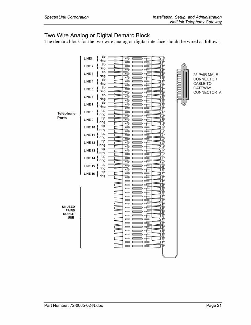
Two Wire Analog or Digital Demarc Block The demarc block for the two-wire analog or digital interface should be wired as follows.
LINE1 tipring
LINE 2 tipring
LINE 3 tipring
LINE 4 tipring
LINE 5 tipring
LINE 6 tipring
LINE 7 tipring
LINE 8 tipring
LINE 9 tipring
tipring
tipring
tipring
LINE 13 tipring
LINE 14 tipring
LINE 15 tipring
LINE 16 tipring
25 PAIR MALECONNECTORCABLE TOGATEWAYCONNECTOR A
TelephonePorts
LINE 10
LINE 11
LINE 12
UNUSEDPAIRS
DO NOTUSE
SpectraLink Corporation Installation, Setup, and Administration NetLink Telephony Gateway
Part Number: 72-0065-02-N.doc Page 22
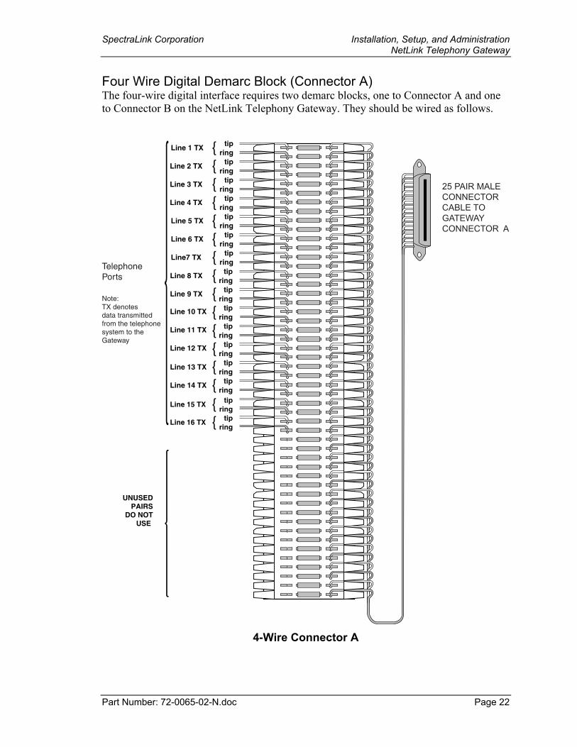
Four Wire Digital Demarc Block (Connector A) The four-wire digital interface requires two demarc blocks, one to Connector A and one to Connector B on the NetLink Telephony Gateway. They should be wired as follows.
Line 1 TX tipring
Line 2 TX tipring
Line 3 TX tipring
Line 4 TX tipring
Line 5 TX tipring
Line 6 TX tipring
Line7 TX tipring
Line 8 TX tipring
Line 9 TX tipring
tipring
tipring
tipring
Line 13 TX tipring
Line 14 TX tipring
Line 15 TX tipring
Line 16 TX tipring
25 PAIR MALECONNECTORCABLE TOGATEWAYCONNECTOR A
TelephonePorts
Line 10 TX
Line 11 TX
Line 12 TX
Note:TX denotesdata transmittedfrom the telephonesystem to theGateway
UNUSEDPAIRS
DO NOTUSE
4-Wire Connector A
SpectraLink Corporation Installation, Setup, and Administration NetLink Telephony Gateway
Part Number: 72-0065-02-N.doc Page 23
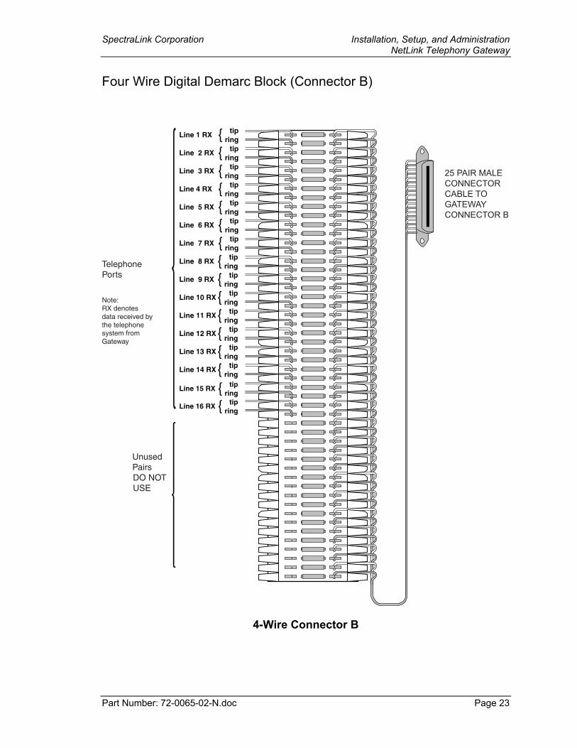
Four Wire Digital Demarc Block (Connector B)
Line 1 RX tipring
Line 2 RX tipring
Line 3 RX tipring
Line 4 RX tipring
Line 5 RX tipring
Line 6 RX tipring
Line 7 RX tipring
Line 8 RX tipring
Line 9 RX tipring
Line 10 RX tipring
Line 11 RX tipring
Line 12 RX tipring
Line 13 RX tipring
Line 14 RX tipring
Line 15 RX tipring
Line 16 RX tipring
25 PAIR MALECONNECTORCABLE TO GATEWAYCONNECTOR B
TelephonePorts
UnusedPairs
Note:RX denotesdata received bythe telephonesystem fromGateway
DO NOTUSE
4-Wire Connector B
SpectraLink Corporation Installation, Setup, and Administration NetLink Telephony Gateway
Part Number: 72-0065-02-N.doc Page 24
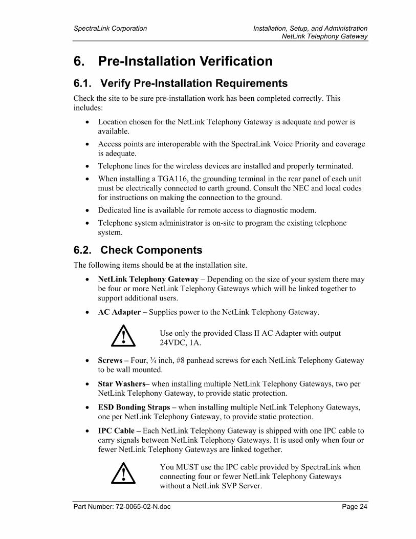
6. Pre-Installation Verification 6.1. Verify Pre-Installation Requirements Check the site to be sure pre-installation work has been completed correctly. This includes:
• Location chosen for the NetLink Telephony Gateway is adequate and power is available.
• Access points are interoperable with the SpectraLink Voice Priority and coverage is adequate.
• Telephone lines for the wireless devices are installed and properly terminated. • When installing a TGA116, the grounding terminal in the rear panel of each unit
must be electrically connected to earth ground. Consult the NEC and local codes for instructions on making the connection to the ground.
• Dedicated line is available for remote access to diagnostic modem. • Telephone system administrator is on-site to program the existing telephone
system.
6.2. Check Components The following items should be at the installation site.
• NetLink Telephony Gateway – Depending on the size of your system there may be four or more NetLink Telephony Gateways which will be linked together to support additional users.
• AC Adapter – Supplies power to the NetLink Telephony Gateway.
Use only the provided Class II AC Adapter with output 24VDC, 1A.
• Screws – Four, ¾ inch, #8 panhead screws for each NetLink Telephony Gateway to be wall mounted.
• Star Washers– when installing multiple NetLink Telephony Gateways, two per NetLink Telephony Gateway, to provide static protection.
• ESD Bonding Straps – when installing multiple NetLink Telephony Gateways, one per NetLink Telephony Gateway, to provide static protection.
• IPC Cable – Each NetLink Telephony Gateway is shipped with one IPC cable to carry signals between NetLink Telephony Gateways. It is used only when four or fewer NetLink Telephony Gateways are linked together.
You MUST use the IPC cable provided by SpectraLink when connecting four or fewer NetLink Telephony Gateways without a NetLink SVP Server.
SpectraLink Corporation Installation, Setup, and Administration NetLink Telephony Gateway
Part Number: 72-0065-02-N.doc Page 25
• NetLink SVP Server – If required, see next section.
• Modem Cable – DB-9 female, null-modem cable. Required for initial setup of the NetLink Telephony Gateway and SVP Server.
• Documentation – Provided on compact disk (CD): SpectraLink Installation Manuals, User Documentation, Wireless Telephone Training.
SpectraLink Corporation Installation, Setup, and Administration NetLink Telephony Gateway
Part Number: 72-0065-02-N.doc Page 26
7. Install NetLink Telephony Gateway The NetLink Telephony Gateways can be mounted either horizontally or vertically. 19 inch rack mount adapters are available.
To Mount Gateways… Connector A is… Mount the Units…. Clearance Between Gateways
Horizontally To the right side of the NetLink Telephony Gateway, with labels in correct position.
On top of one another
Leave a little more than ¼ inch between adjacent units, allowing easy removal of units via the keyhole openings on the rear panel.
Do not leave more than ½ inch spacing or the ESD bonding strap will not fit correctly.
To set the desired unit spacing, leave (0.9” + desired gap) between adjacent mounting holes.
Vertically At the top of the NetLink Telephony Gateway
Side by side Adjacent units should be physically touching
Mount the NetLink Telephony Gateway to rack The Rack Mount Kit is designed for mounting equipment in a standard 19-inch rack and should contain the following equipment:
• Mounting plates – two for each Gateway to be mounted. • Screws – four rack mount screws for each Gateway to be mounted.
To rack-mount one NetLink Telephony Gateway: 1. Remove the corner screws from the Gateway.
2. Screw the U-shaped end (round screw holes) of the two mounting plates to the Gateway. Screw the other end of the two mounting plates (oblong screw holes) to the rack. Connector A should be to the right.
Mount NetLink Telephony Gateway to wall To mount one NetLink Telephony Gateway:
1. Using a 1/8-inch drill bit, drill four pilot holes, on 1.84 by 12.1 inch centers (approximately equivalent to 1-13/16 inch by 12-1/8 inch).
2. If installing only one NetLink Telephony Gateway, insert the #8 x 3/4 inch screws in the pilot holes and tighten, leaving a 1/8 to 1/4 inch gap from the wall. Position the NetLink Telephony Gateway with Connector A to the right (horizontal) or bottom (vertical). Slide the NetLink Telephony Gateway over the screws until the unit drops into place in the keyhole opening.
SpectraLink Corporation Installation, Setup, and Administration NetLink Telephony Gateway
Part Number: 72-0065-02-N.doc Page 27
Installing multiple NetLink Telephony Gateways If installing more than one NetLink Telephony Gateway, the ESD bonding strap(s) must be installed between adjacent gateways:
1. Remove the screws from the bottom (vertical mount) or left (horizontal mount) of adjacent units.
2. Place the ESD strap over the pilot holes that span two units and hold it against the plywood backboard or rack.
3. Place the star washer on top of the ESD strap.
4. Insert the #8 x ¾ screw and tighten to leave 1/8 to 1/4 inch gap from the wall.
5. Repeat for all ESD straps.
6. Position the NetLink Telephony Gateway with Connector A to the right (horizontal) or bottom (vertical). Slide the NetLink Telephony Gateway over the screws until the unit drops into place in the keyhole opening.
7. Tighten screws fully.
When installing a TGA116, the grounding terminal in the rear panel of each unit must be electrically connected to earth ground. Consult the NEC and local codes for instructions on making the connection to the ground.
Connect NetLink Telephony Gateway to demarc blocks Connect the male RJ-21 connector from the appropriate demarcation block to the designated RJ-21 connector (A or B) on each NetLink Telephony Gateway. Secure the cables using the keeper.
SpectraLink Corporation Installation, Setup, and Administration NetLink Telephony Gateway
Part Number: 72-0065-02-N.doc Page 28
Connect four or fewer NetLink Telephony Gateways with IPC cables To connect four or fewer NetLink Telephony Gateways:
1. Mount the NetLink Telephony Gateways.
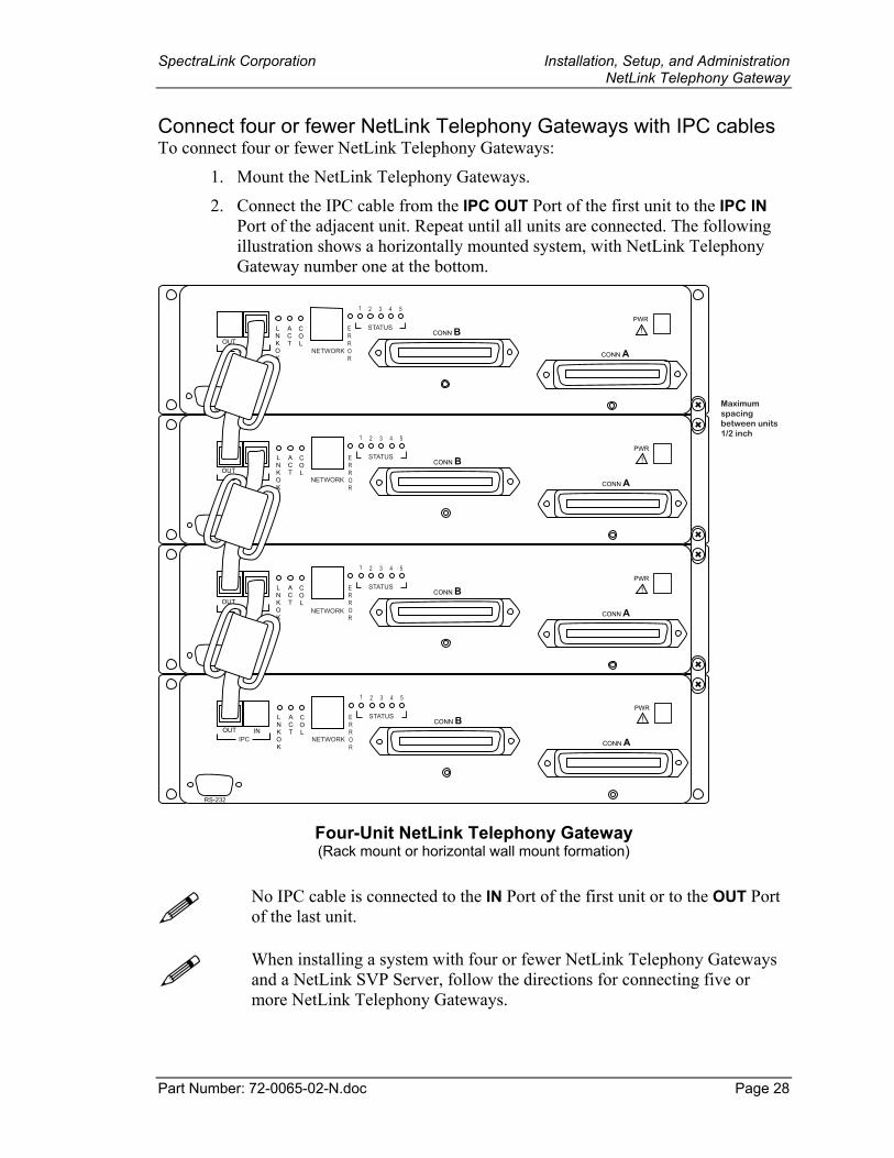
2. Connect the IPC cable from the IPC OUT Port of the first unit to the IPC IN Port of the adjacent unit. Repeat until all units are connected. The following illustration shows a horizontally mounted system, with NetLink Telephony Gateway number one at the bottom.
PWR
CONN B
CONN A
ERROR
1 2 3 4 5
STATUS !
RS-232
LNKOK
ACT
COL
PWR
CONN B
CONN A
ERROR
1 2 3 4 5
STATUS !
RS-232
LNKOK
ACT
COL
PWR
CONN B
CONN A
ERROR
1 2 3 4 5
STATUS !
RS-232
LNKOK
ACT
COL
PWR
CONN B
CONN A
ERROR
1 2 3 4 5
STATUS !
RS-232
LNKOK
ACT
COL
IPC NETWORKOUT IN
IPC NETWORKOUT IN
IPC NETWORKOUT IN
IPC NETWORKOUT IN
������� �
�����
������ �����
��� ���
Four-Unit NetLink Telephony Gateway (Rack mount or horizontal wall mount formation)
No IPC cable is connected to the IN Port of the first unit or to the OUT Port of the last unit.
When installing a system with four or fewer NetLink Telephony Gateways and a NetLink SVP Server, follow the directions for connecting five or more NetLink Telephony Gateways.
SpectraLink Corporation Installation, Setup, and Administration NetLink Telephony Gateway
Part Number: 72-0065-02-N.doc Page 29
Connect five or more NetLink Telephony Gateways To mount five or more NetLink Telephony Gateways:
• Mount the NetLink Telephony Gateways on the backboard or rack. • No IPC cable connection is required for five or more NetLink Telephony
Gateways. Simply connect each NetLink Telephony Gateway to the local area network via an Ethernet Switch.
• This system configuration requires a NetLink SVP Server. See the document NetLink SVP Server: Installation, Setup, and Maintenance.
Connect NetLink Telephony Gateway to LAN Each Gateway requires a separate Ethernet connection on an Ethernet switch. Using an RJ-45 cable, connect the NETWORK port on each NetLink Telephony Gateway to the connecting port on the same Ethernet switch.
Connect power 1. Connect the power plug from the AC adapter to the jack labeled PWR on the
NetLink Telephony Gateway.
Use only the provided Class II AC Adapter with output 24VDC, 1A.
For proper operation, all NetLink Telephony Gateways must be powered on and off at the same time. For installations with more than one NetLink Telephony Gateway, use an outlet strip with a built in power switch to allow NetLink Telephony Gateways to be turned on and off together.
2. Plug the AC adapter into a 110VAC outlet or switch on the outlet strip to apply power to the NetLink Telephony Gateway.
3. The system will cycle through diagnostic testing and the LEDs will blink for about one minute. When the system is ready for use:
• The E (error) LED should be off on each NetLink Telephony Gateway
• Status 1 should be blinking on each NetLink Telephony Gateway
• Status 5 should be lit on one and only one NetLink Telephony Gateway. If Status 5 is lit on more than one NetLink Telephony Gateway, the NetLink Telephony Gateways are not correctly connected to one another.
After the NetLink Telephony Gateways are installed, you must configure each NetLink Telephony Gateway and Wireless Telephone.
SpectraLink Corporation Installation, Setup, and Administration NetLink Telephony Gateway
Part Number: 72-0065-02-N.doc Page 30
8. NetLink Telephony Gateway Administration Overview
The NetLink Telephony Gateway(s) and Wireless Telephones are administered and maintained through a series of menu options for each NetLink Telephony Gateway in the system. The NetLink SVP Server has a separate set of menus that are covered in a separate document – NetLink SVP Server: Installation, Setup and Maintenance.
System menus are usually viewed via an administrative computer that is connected to a NetLink Telephony Gateway via the serial port or through a Telnet session on the LAN. An external modem may alternately be used for viewing system menus. The series of screens containing menus and options for configuring and maintaining the NetLink components is called the Administration Console. Maintenance functions include:
• Configuring the NetLink Telephony Gateway’s network parameters and its interface to the host telephone system.
• Configuring each NetLink Telephony Gateway’s Wireless Telephones, including adding and deleting Wireless Telephones.
• Programming the Wireless Telephone’s menu and features associated with PBX functions.
• Reviewing system status to check usage and diagnose system problems. Wireless Telephones have a separate administration document that is used in conjunction with this one for complete system administration and maintenance. See NetLink Wireless Telephone: Setup and Administration.
Access Points move information between the wireless local area network (LAN) and the wired LAN. They are NOT configured from the Administration Console. They are administered independently as covered in the Configuration Note for the specific type of access point in use.
SpectraLink Corporation Installation, Setup, and Administration NetLink Telephony Gateway
Part Number: 72-0065-02-N.doc Page 31
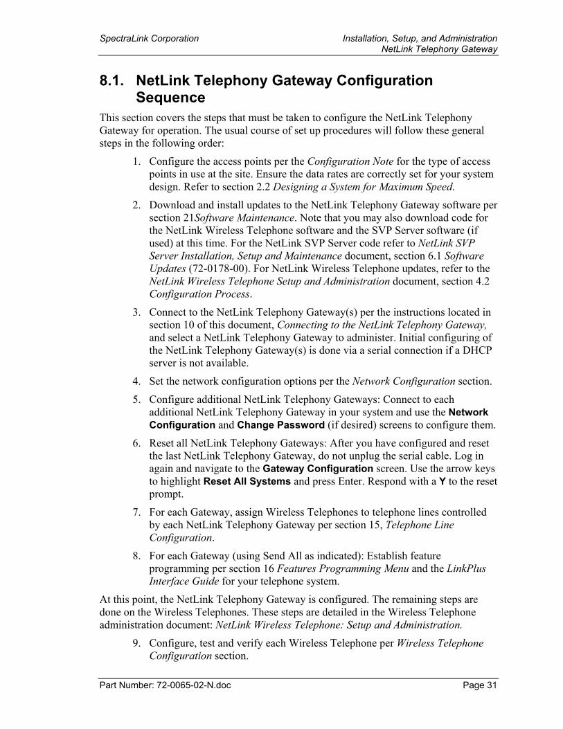
8.1. NetLink Telephony Gateway Configuration Sequence
This section covers the steps that must be taken to configure the NetLink Telephony Gateway for operation. The usual course of set up procedures will follow these general steps in the following order:
1. Configure the access points per the Configuration Note for the type of access points in use at the site. Ensure the data rates are correctly set for your system design. Refer to section 2.2 Designing a System for Maximum Speed.
2. Download and install updates to the NetLink Telephony Gateway software per section 21Software Maintenance. Note that you may also download code for the NetLink Wireless Telephone software and the SVP Server software (if used) at this time. For the NetLink SVP Server code refer to NetLink SVP Server Installation, Setup and Maintenance document, section 6.1 Software Updates (72-0178-00). For NetLink Wireless Telephone updates, refer to the NetLink Wireless Telephone Setup and Administration document, section 4.2 Configuration Process.
3. Connect to the NetLink Telephony Gateway(s) per the instructions located in section 10 of this document, Connecting to the NetLink Telephony Gateway, and select a NetLink Telephony Gateway to administer. Initial configuring of the NetLink Telephony Gateway(s) is done via a serial connection if a DHCP server is not available.
4. Set the network configuration options per the Network Configuration section.
5. Configure additional NetLink Telephony Gateways: Connect to each additional NetLink Telephony Gateway in your system and use the Network Configuration and Change Password (if desired) screens to configure them.
6. Reset all NetLink Telephony Gateways: After you have configured and reset the last NetLink Telephony Gateway, do not unplug the serial cable. Log in again and navigate to the Gateway Configuration screen. Use the arrow keys to highlight Reset All Systems and press Enter. Respond with a Y to the reset prompt.
7. For each Gateway, assign Wireless Telephones to telephone lines controlled by each NetLink Telephony Gateway per section 15, Telephone Line Configuration.
8. For each Gateway (using Send All as indicated): Establish feature programming per section 16 Features Programming Menu and the LinkPlus Interface Guide for your telephone system.
At this point, the NetLink Telephony Gateway is configured. The remaining steps are done on the Wireless Telephones. These steps are detailed in the Wireless Telephone administration document: NetLink Wireless Telephone: Setup and Administration.
9. Configure, test and verify each Wireless Telephone per Wireless Telephone Configuration section.
SpectraLink Corporation Installation, Setup, and Administration NetLink Telephony Gateway
Part Number: 72-0065-02-N.doc Page 32
10. Perform access point coverage test per Certifying the NetLink System section.
11. Call Customer Support at SpectraLink for Site Certification.
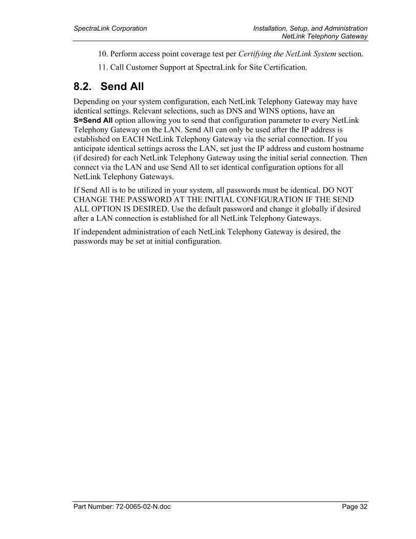
8.2. Send All Depending on your system configuration, each NetLink Telephony Gateway may have identical settings. Relevant selections, such as DNS and WINS options, have an S=Send All option allowing you to send that configuration parameter to every NetLink Telephony Gateway on the LAN. Send All can only be used after the IP address is established on EACH NetLink Telephony Gateway via the serial connection. If you anticipate identical settings across the LAN, set just the IP address and custom hostname (if desired) for each NetLink Telephony Gateway using the initial serial connection. Then connect via the LAN and use Send All to set identical configuration options for all NetLink Telephony Gateways.
If Send All is to be utilized in your system, all passwords must be identical. DO NOT CHANGE THE PASSWORD AT THE INITIAL CONFIGURATION IF THE SEND ALL OPTION IS DESIRED. Use the default password and change it globally if desired after a LAN connection is established for all NetLink Telephony Gateways.
If independent administration of each NetLink Telephony Gateway is desired, the passwords may be set at initial configuration.
SpectraLink Corporation Installation, Setup, and Administration NetLink Telephony Gateway
Part Number: 72-0065-02-N.doc Page 33
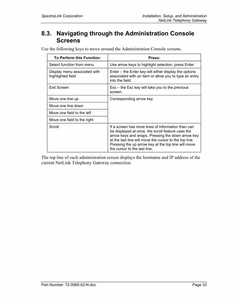
8.3. Navigating through the Administration Console Screens
Use the following keys to move around the Administration Console screens.
To Perform this Function: Press:
Select function from menu Use arrow keys to highlight selection, press Enter
Display menu associated with highlighted field
Enter – the Enter key will either display the options associated with an item or allow you to type an entry into the field.
Exit Screen Esc – the Esc key will take you to the previous screen.
Move one line up
Move one line down
Move one field to the left
Move one field to the right
Corresponding arrow key
Scroll If a screen has more lines of information than can be displayed at once, the scroll feature uses the arrow keys and wraps. Pressing the down arrow key at the last line will move the cursor to the top line. Pressing the up arrow key at the top line will move the cursor to the last line.
The top line of each administration screen displays the hostname and IP address of the current NetLink Telephony Gateway connection.
SpectraLink Corporation Installation, Setup, and Administration NetLink Telephony Gateway
Part Number: 72-0065-02-N.doc Page 34
9. Connecting to the NetLink Telephony Gateway
For the initial configuration of each NetLink Telephony Gateway, you should have the Wireless Device Planning Worksheet(s) that was filled out during the installation of the system. There should be one for each NetLink Telephony Gateway. The following items included in the Worksheets must be known before proceeding with the setup:
• NetLink Telephony Gateway hostname (usually the default name is replaced with a locally-designated identifier)
• PBX (Private Branch Exchange) type • Active calls per access point (see the Configuration Note for the system’s access
points for this data) • IP Address (if static IP addresses are established by the LAN administrator).
If you have a DHCP Server, it will assign an IP address to the NetLink Telephony Gateway. In this case, you can use Telnet to configure and administer the Gateway and do not need an initial serial connection to assign the IP address.
9.1. Connect via the Serial Port The serial connection is used in lieu of DHCP in systems that choose not to assign NetLink Telephony Gateway IP addresses via a DHCP Server, in which case a static IP address is required.
1. Using a DB-9 female, null-modem cable, connect any NetLink Telephony Gateway to the serial port of a terminal or PC.
2. Run a terminal emulation program (such as HyperTerminal™) or use a VT-100 terminal with the following configuration: Bits per second: 9600 Data bits: 8 Parity: None Stop bits: 1 Flow control: None
3. Press Enter to display the NetLink Telephony Gateway login screen.
4. Enter the default login: admin and default password: admin. These are case sensitive.
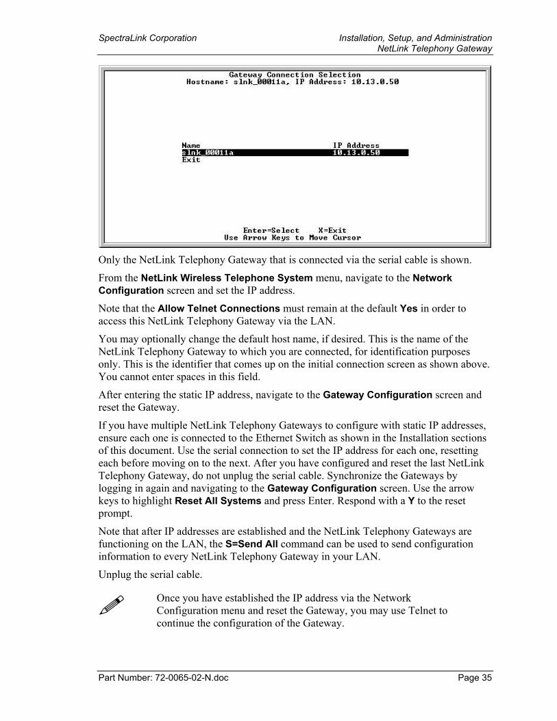
5. The Gateway Connection Selection screen lists this NetLink Telephony Gateway(s) and its factory default name.
SpectraLink Corporation Installation, Setup, and Administration NetLink Telephony Gateway
Part Number: 72-0065-02-N.doc Page 35
Only the NetLink Telephony Gateway that is connected via the serial cable is shown.
From the NetLink Wireless Telephone System menu, navigate to the Network Configuration screen and set the IP address.
Note that the Allow Telnet Connections must remain at the default Yes in order to access this NetLink Telephony Gateway via the LAN.
You may optionally change the default host name, if desired. This is the name of the NetLink Telephony Gateway to which you are connected, for identification purposes only. This is the identifier that comes up on the initial connection screen as shown above. You cannot enter spaces in this field.
After entering the static IP address, navigate to the Gateway Configuration screen and reset the Gateway.
If you have multiple NetLink Telephony Gateways to configure with static IP addresses, ensure each one is connected to the Ethernet Switch as shown in the Installation sections of this document. Use the serial connection to set the IP address for each one, resetting each before moving on to the next. After you have configured and reset the last NetLink Telephony Gateway, do not unplug the serial cable. Synchronize the Gateways by logging in again and navigating to the Gateway Configuration screen. Use the arrow keys to highlight Reset All Systems and press Enter. Respond with a Y to the reset prompt.
Note that after IP addresses are established and the NetLink Telephony Gateways are functioning on the LAN, the S=Send All command can be used to send configuration information to every NetLink Telephony Gateway in your LAN.
Unplug the serial cable.
Once you have established the IP address via the Network Configuration menu and reset the Gateway, you may use Telnet to continue the configuration of the Gateway.
SpectraLink Corporation Installation, Setup, and Administration NetLink Telephony Gateway
Part Number: 72-0065-02-N.doc Page 36
9.2. Connecting Via Telnet In addition to the serial connection described in the previous section, connection to the NetLink Telephony Gateway may be done via the network using Telnet. Once the IP addresses are configured, every NetLink Telephony Gateway is accessible through a connection to any NetLink Telephony Gateway.
If you do not have a DHCP Server, Telnet can only be used after the NetLink Telephony Gateway’s IP address is configured. See the previous section.
The Telnet method of connection is used for routine maintenance of the system for both local and remote administration, depending on your network.
To connect via Telnet, run a Telnet session to the IP address of any NetLink Telephony Gateway. Once you connect to any NetLink Telephony Gateway and log in, the Gateway Connection Selection screen displays.
Select the NetLink Telephony Gateway you wish to administer and press Enter.
The top line of each administration screen displays the hostname and IP address of the NetLink Telephony Gateway on which you are currently operating.
9.3. Connecting Via External Modem The external modem method of connection is most frequently used for routine maintenance of the system when administration of the system is remotely done, and the network itself is not remotely accessible.
You will need a standard analog phone line for the modem. (A digital line from a digital PBX will not work.) Consult with your telephone system vendor or the Telephone Company for more information about dialing into a modem.
If needed, the external modem generally should maintain its default settings, except Hardware Flow Control must be disabled.
The following settings use the US Robotics Sportster modem. Other modem models may be used, but the particular model’s settings will have to be adapted to conform to those listed in the following table.
SpectraLink Corporation Installation, Setup, and Administration NetLink Telephony Gateway
Part Number: 72-0065-02-N.doc Page 37
Configure Modem Internal Settings (US Robotics Sportster) 1. Connect the modem to a PC using a standard modem cable. Plug the 9-pin
connector into the RS-232 port on the PC, and the 25-pin connector into the modem’s port.
2. Using a standard communications package such as ProComm Plus or HyperTerminal™, bring up the modem and type the following commands. Press Enter after typing each command.
Command Description
AT&F1 Loads factory default settings
AT&H0 Sets Transmit Data Flow control to disabled
AT&R1 Sets modem to ignore Request to Send (RTS)
AT&W0 Saves the configuration
3. Power off the modem, and then turn it back on.
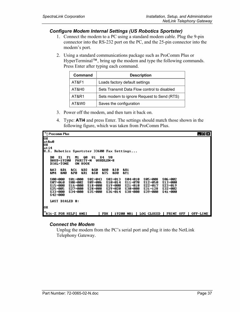
4. Type: ATI4 and press Enter. The settings should match those shown in the following figure, which was taken from ProComm Plus.
Connect the Modem Unplug the modem from the PC’s serial port and plug it into the NetLink Telephony Gateway.
SpectraLink Corporation Installation, Setup, and Administration NetLink Telephony Gateway
Part Number: 72-0065-02-N.doc Page 38
9.4. Connecting via Internal Modem
An internal 2400-baud modem is built into the NetLink Telephony Gateway. Line one can be configured to connect via this modem. The modem is only used by SpectraLink Customer Service to assist in troubleshooting problems by remotely accessing the gateway. If this is required Customer Service personnel will give instructions on how to configure the modem.
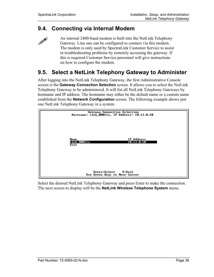
9.5. Select a NetLink Telephony Gateway to Administer After logging into the NetLink Telephony Gateway, the first Administrative Console screen is the Gateway Connection Selection screen. It allows you to select the NetLink Telephony Gateway to be administered. It will list all NetLink Telephony Gateways by hostname and IP address. The hostname may either be the default name or a custom name established from the Network Configuration screen. The following example shows just one NetLink Telephony Gateway in a system:
Select the desired NetLink Telephony Gateway and press Enter to make the connection. The next screen to display will be the NetLink Wireless Telephone System menu.
SpectraLink Corporation Installation, Setup, and Administration NetLink Telephony Gateway
Part Number: 72-0065-02-N.doc Page 39
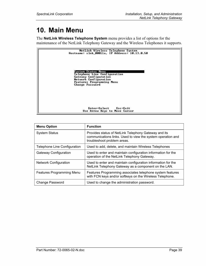
10. Main Menu The NetLink Wireless Telephone System menu provides a list of options for the maintenance of the NetLink Telephony Gateway and the Wireless Telephones it supports.
Menu Option Function
System Status Provides status of NetLink Telephony Gateway and its communications links. Used to view the system operation and troubleshoot problem areas.
Telephone Line Configuration Used to add, delete, and maintain Wireless Telephones
Gateway Configuration Used to enter and maintain configuration information for the operation of the NetLink Telephony Gateway.
Network Configuration Used to enter and maintain configuration information for the NetLink Telephony Gateway as a component on the LAN.
Features Programming Menu Features Programming associates telephone system features with FCN keys and/or softkeys on the Wireless Telephone.
Change Password Used to change the administration password.
SpectraLink Corporation Installation, Setup, and Administration NetLink Telephony Gateway
Part Number: 72-0065-02-N.doc Page 40
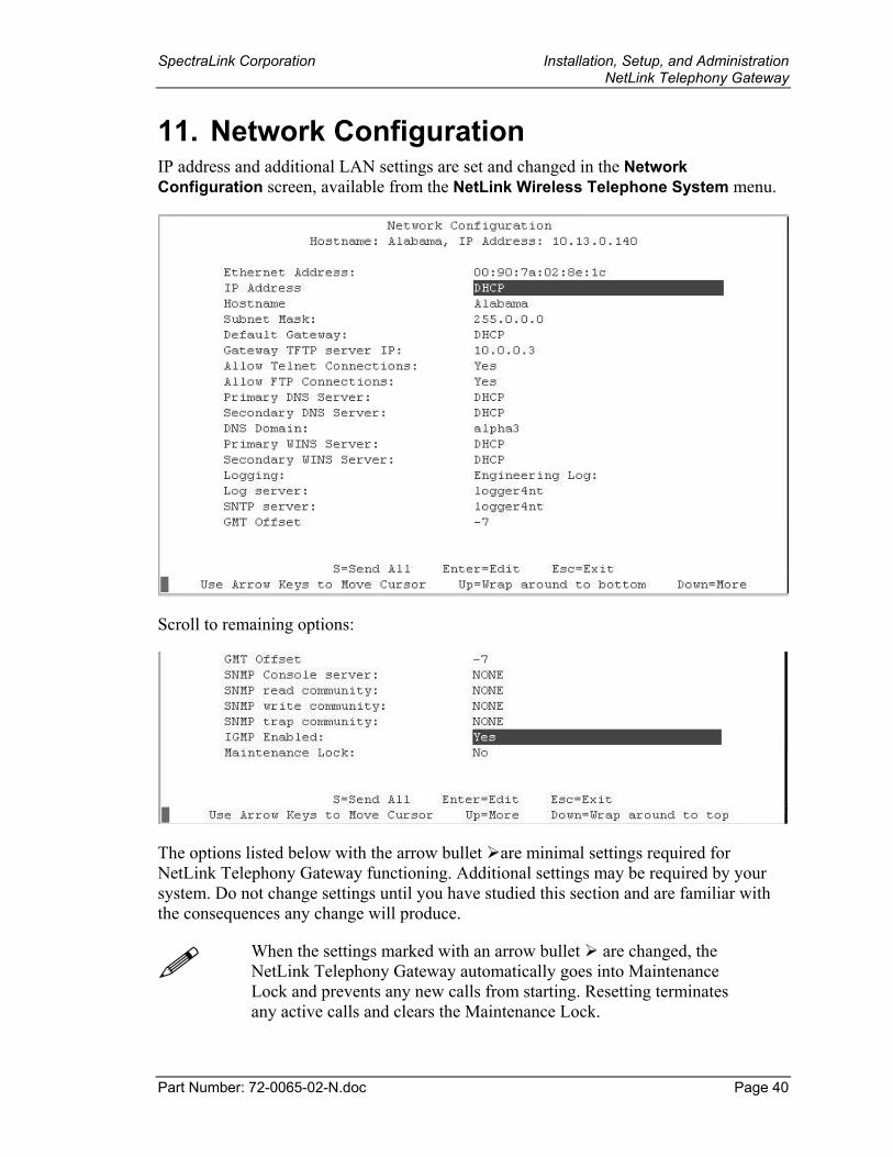
11. Network Configuration IP address and additional LAN settings are set and changed in the Network Configuration screen, available from the NetLink Wireless Telephone System menu.
Scroll to remaining options:
The options listed below with the arrow bullet are minimal settings required for NetLink Telephony Gateway functioning. Additional settings may be required by your system. Do not change settings until you have studied this section and are familiar with the consequences any change will produce.
When the settings marked with an arrow bullet are changed, the NetLink Telephony Gateway automatically goes into Maintenance Lock and prevents any new calls from starting. Resetting terminates any active calls and clears the Maintenance Lock.
SpectraLink Corporation Installation, Setup, and Administration NetLink Telephony Gateway
Part Number: 72-0065-02-N.doc Page 41
• Ethernet Address – The MAC address of the NetLink Telephony Gateway, set at the factory and not user configurable. IP Address – Established in the initial serial connection and may be changed as
needed. This is the IP address of the NetLink Telephony Gateway as defined by your network administrator. Enter the complete address including digits and periods. DHCP may be entered and if so, the S=Send All option allows you to configure all NetLink Telephony Gateways with DHCP. Hostname – The hostname identifies this particular NetLink Telephony Gateway
and is for identification purposes only. The default name may be changed to something locally suitable. You cannot enter spaces in this field.
• Subnet Mask – The network administrator must define the subnet mask. • Default Gateway – IP address of a router on the local subnet. • Allow Telnet Connections – Enter Yes to allow connection to the NetLink
Telephony Gateway via Telnet; enter No if you do not want to allow Telnet connection.
• Allow FTP Connections – Enter Yes to allow the NetLink Telephony Gateway to communicate via FTP; enter No if you do not want to allow this. FTP is used for software updates as well as to backup and restore software configuration. See the Software Maintenance section for more information about FTP.
The Allow Telnet and Allow FTP Connections options are security points. If both of these are disabled, the only method for accessing the NetLink Telephony Gateway will be via serial connection.
• DNS server and DNS domain – These settings are used to configure Domain Name services. Consult your system administrator for the correct settings. These can also be set to DHCP. This will cause the DHCP client in the gateway to attempt to automatically get the correct setting from the DHCP server. The DHCP setting is only valid when the IP address is also acquired using DHCP.
• WINS servers – These setting are used for Windows Internet Name Services. Consult your system administrator for the correct settings. These can also be set to DHCP. This will cause the DHCP client in the gateway to attempt to automatically get the correct setting from the DHCP server. The DHCP setting is only valid when the IP address is also acquired DHCP.
When the name services are set up correctly, the NetLink Telephony Gateway can translate hostnames to IP addresses. Using Telnet, it is also possible to access the NetLink Telephony Gateways using their hostname instead of the IP address.
• Logging and Log server – Logging can be set to Syslog or NONE. The log server is the IP address or hostname of the Syslog server on the network. The gateway will output syslog format diagnostic messages. This is usually not needed.
• SNTP – The SNTP (Simple Network Time Protocol) server provides a time stamp for syslog messages. See the Setup and Administration document for the Wireless
SpectraLink Corporation Installation, Setup, and Administration NetLink Telephony Gateway
Part Number: 72-0065-02-N.doc Page 42
Telephone for detailed information about syslog messages. If syslog is being used, then SNTP server should be set to the hostname or IP address of an SNTP server.
• GMT Offset – Difference in hours from Greenwich Mean Time, used for time stamping by SNTP. There is no automatic adjustment for Daylight Savings Time. Enter –0 to –12 for zones that are earlier than GMT and +0 to +12 for zones that are later than GMT. Example: Mountain Standard Time is –7, or –6 during DST.
• SNMP – Simple Network Management Protocol: Enter the IP address of the SNMP server to allow alarms and other simple events to be sent from the NetLink Gateway to the SNMP server. More specific configuration information is not sent. MIB Support: SpectraLink currently supports SNMP V2c (also known as community-based V2). The supported MIB is MIB2 and includes the following:
SNMP MIB IP-MIB TCP-MIB UDP-MIB IF-MIB (interfaces) EtherLike-MIB (ethernet interface)
The following custom MIB definitions are available on the SpectraLink Web site at Hhttp://www.spectralink.com/service/software.phpH:
SPECTRALINK-ENTERPRISE.TXT NETLINK-COMMON.TXT NETLINK-CAPABILITIES.TXT
• IGMP – Internet Group Management Protocol: Yes enables, No disables. This is used for managing multicast traffic. It should typically be set to Yes.
• Maintenance Lock – The system automatically sets this option to Yes after certain maintenance activities that require reset. These are indicated in this list with an arrow bullet. Maintenance Lock prevents any new calls from starting. Note that the administrator cannot change this option. It is automatically set by the system. Reset the system at exit to clear Maintenance Lock.
Press Esc to return to the NetLink Wireless Telephone System menu.
Note that resetting the NetLink Telephony Gateway(s) will terminate any calls in progress on the NetLink Telephony Gateway(s) being reset.
All NetLink Telephony Gateways should be reset at the end of any maintenance procedure that requires any one NetLink Telephony Gateway to be reset either via Maintenance Lock or manually via Reset System. Resetting them all keeps the NetLink Telephony Gateways synchronized, which is important for proper system function.
SpectraLink Corporation Installation, Setup, and Administration NetLink Telephony Gateway
Part Number: 72-0065-02-N.doc Page 43
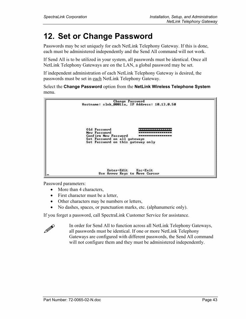
12. Set or Change Password Passwords may be set uniquely for each NetLink Telephony Gateway. If this is done, each must be administered independently and the Send All command will not work.
If Send All is to be utilized in your system, all passwords must be identical. Once all NetLink Telephony Gateways are on the LAN, a global password may be set.
If independent administration of each NetLink Telephony Gateway is desired, the passwords must be set in each NetLink Telephony Gateway.
Select the Change Password option from the NetLink Wireless Telephone System menu.
Password parameters:
• More than 4 characters, • First character must be a letter, • Other characters may be numbers or letters, • No dashes, spaces, or punctuation marks, etc. (alphanumeric only).
If you forget a password, call SpectraLink Customer Service for assistance.
In order for Send All to function across all NetLink Telephony Gateways, all passwords must be identical. If one or more NetLink Telephony Gateways are configured with different passwords, the Send All command will not configure them and they must be administered independently.
SpectraLink Corporation Installation, Setup, and Administration NetLink Telephony Gateway
Part Number: 72-0065-02-N.doc Page 44
13. NetLink Telephony Gateway Configuration
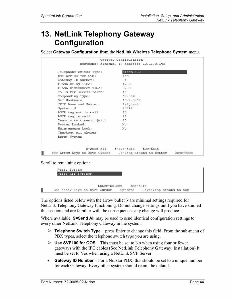
Select Gateway Configuration from the NetLink Wireless Telephone System menu.
Scroll to remaining option:
The options listed below with the arrow bullet are minimal settings required for NetLink Telephony Gateway functioning. Do not change settings until you have studied this section and are familiar with the consequences any change will produce.
Where available, S=Send All may be used to send identical configuration settings to every other NetLink Telephony Gateway in the system.
Telephone Switch Type – press Enter to change this field. From the sub-menu of PBX types, select the telephone switch type you are using. Use SVP100 for QOS – This must be set to No when using four or fewer
gateways with the IPC cables (See NetLink Telephony Gateway: Installation) It must be set to Yes when using a NetLink SVP Server.
• Gateway ID Number – For a Norstar PBX, this should be set to a unique number for each Gateway. Every other system should retain the default.
SpectraLink Corporation Installation, Setup, and Administration NetLink Telephony Gateway
Part Number: 72-0065-02-N.doc Page 45
• Flash Delay Time– (analog interface only) the time the system should wait after the “on-hook” flash signal ends before allowing other keys to be transmitted to the host telephone system. The allowed range is from .01 to 2 seconds. The value depends on the requirements of the host telephone system.
• Flash Disconnect Time – (analog interface only) the length of time the system should be “on-hook” when the user presses the Start key during a call, or uses a macro that includes a Flash code. The allowed range is from .01 to 2 seconds. The value depends on the requirements of the host telephone system. Calls Per Access Point - maximum number of active Wireless Telephone calls
per access point. Refer to the Configuration Notes for your APs for this information or consult your wireless LAN system administrator. This number should be the same on all NetLink Telephony Gateways in the system. Companding Type - signal compression type. Mu-law is standard format in most
host telephone systems in North America. A-law is typically used in Mexico. If the companding type of the NetLink Telephony Gateway does not match that of the host telephone system the Wireless Telephones will have distorted dial tone and unintelligible voice quality.
• OAI hostname - valid entries: Local - if the OAI Gateway is on the same subnet.
IP Address - if the OAI Gateway is on another subnet.
NONE – if no OAI Gateway is on the system.
• TFTP Download Master - this entry indicates the source of software updates for the Wireless Telephones associated with this NetLink Telephony Gateway. Software updates received from SpectraLink must be placed in this location. See section 13, Software Maintenance, for more information. When the Wireless Telephone is turned on, it checks this source for confirmation that it is running the correct software version. If there is any discrepancy, the Wireless Telephone will download the software that resides in this source location.
Valid source location entries are: Gateway - (NetLink Telephony Gateway default) - indicates that the
Wireless Telephones will get software from this Gateway.
IP Address - the IP address of a network TFTP server that will be used to transfer software updates to the Wireless Telephones.
Hostname – the hostname of the network TFTP server that will be used to transfer software updates to the Wireless Telephones. DNS or WINS must be configured correctly to use a hostname.
NONE – disables the TFTP download of Wireless Telephones.
• DSCP tag not in call/in call – DSCP (Differentiated Services Code Point) is a QoS mechanism for setting relative priorities. Packets are tagged with a DSCP field in the IP header for type of service. The value may be set as a number from 0-255 and may be different for in call/not in call modes.
SpectraLink Corporation Installation, Setup, and Administration NetLink Telephony Gateway
Part Number: 72-0065-02-N.doc Page 46
• Inactivity Timeout (min): Set the number of minutes the administrative module can be left unattended before the system closes it. This number can be from 1 to 100. If it is set to zero (0), the administrative module will not close due to inactivity.
• System Locked - This option is used to take the system down for maintenance. The default entry is No. Set it at Yes to prevent any new calls from starting. Return to No to restore normal operation.
• Maintenance Lock - The system automatically sets this option to Yes after certain maintenance activities that require reset, and certain alarms that cause the system to be inoperable. Such maintenance activities are indicated in this list with an arrow bullet. Maintenance Lock prevents any new calls from starting. Note that the administrator cannot change this option. It is automatically set by the system. Reset the system at exit to clear Maintenance Lock.
The NetLink Telephony Gateway monitors the condition of any NetLink SVP Server(s) on the system. In a single NetLink SVP Server system, when the SVP Server goes into Maintenance Lock, the Telephony Gateway will also lock and set an alarm. No new calls will be allowed but calls in progress will not be affected.
In multiple SVP Server systems, when one SVP Server goes into Maintenance Lock, it sends a message to the Telephony Gateway(s) which will stop using the locked SVP Server. It may take up to 30 seconds for the message to reach the Telephony Gateway. If all SVP Servers lock, then the Telephony Gateway will also lock and set an alarm. No new calls will be allowed bu calls in progress will not be affected.
• Checkout all phones – If the TFTP server is on a PC, this command is used to upgrade each Wireless Telephone without having to reset the Gateway. This command forces all the Wireless Telephones on the system to check in with the Gateway. They will check their current software version vs. the version stored on the TFTP server and download if needed. Any handsets in a call will perform their checkout after the call is complete.
• Reset System - if this option is selected, you will be prompted to reset this NetLink Telephony Gateway.
• Reset All Systems - if this option is selected, you will be prompted to reset all NetLink Telephony Gateways.
Press Esc to return to the NetLink Wireless Telephone System menu.
SpectraLink Corporation Installation, Setup, and Administration NetLink Telephony Gateway
Part Number: 72-0065-02-N.doc Page 47
13.1. Resetting the NetLink Telephony Gateway Note that resetting the NetLink Telephony Gateway(s) will terminate any calls in progress on the NetLink Telephony Gateway(s) being reset.
All NetLink Telephony Gateways should be reset at the end of any maintenance procedure that requires any one NetLink Telephony Gateway to be reset either via Maintenance Lock or manually via Reset System. Resetting them all keeps the NetLink Telephony Gateways synchronized, which is important for proper system functioning.
The NetLink Telephony Gateways are ready to operate. The next step is to configure the lines used by the Wireless Telephones. See the next section: Telephone Line Configuration.
Note that after the Wireless Telephones are added and the system is running, additional configuration options may be chosen to adjust the system for your usage situation.
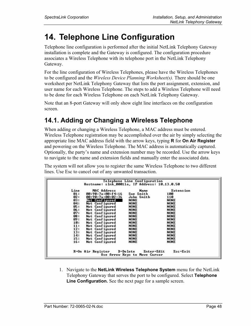
SpectraLink Corporation Installation, Setup, and Administration NetLink Telephony Gateway
Part Number: 72-0065-02-N.doc Page 48
14. Telephone Line Configuration Telephone line configuration is performed after the initial NetLink Telephony Gateway installation is complete and the Gateway is configured. The configuration procedure associates a Wireless Telephone with its telephone port in the NetLink Telephony Gateway.
For the line configuration of Wireless Telephones, please have the Wireless Telephones to be configured and the Wireless Device Planning Worksheet(s). There should be one worksheet per NetLink Telephony Gateway that lists the port assignment, extension, and user name for each Wireless Telephone. The steps to add a Wireless Telephone will need to be done for each Wireless Telephone on each NetLink Telephony Gateway.
Note that an 8-port Gateway will only show eight line interfaces on the configuration screen.
14.1. Adding or Changing a Wireless Telephone When adding or changing a Wireless Telephone, a MAC address must be entered. Wireless Telephone registration may be accomplished over the air by simply selecting the appropriate line MAC address field with the arrow keys, typing R for On Air Register and powering on the Wireless Telephone. The MAC address is automatically captured. Optionally, the party’s name and extension number may be recorded. Use the arrow keys to navigate to the name and extension fields and manually enter the associated data.
The system will not allow you to register the same Wireless Telephone to two different lines. Use Esc to cancel out of any unwanted transaction.
1. Navigate to the NetLink Wireless Telephone System menu for the NetLink Telephony Gateway that serves the port to be configured. Select Telephone Line Configuration. See the next page for a sample screen.
SpectraLink Corporation Installation, Setup, and Administration NetLink Telephony Gateway
Part Number: 72-0065-02-N.doc Page 49
2. Enter the following information for each assigned line. Use the arrow keys to navigate through the fields.
MAC Address - the MAC address is printed on the sticker underneath the battery on the Wireless Telephone. It can also be displayed on the Wireless Telephone by turning off the Wireless Telephone, and then pressing and holding the Power On button. The MAC address appears on the first line of the display (12 characters). The MAC address can be manually entered by typing the entire address including digits and colons.
The MAC address can be automatically entered by typing R and following the prompts to turn on the Wireless Telephone.
Name - enter the user name assigned to the telephone. This is for record keeping only; it does not communicate the name to the PBX or the Wireless Telephone.
Extension - enter the extension assigned to this telephone. This is for record keeping only; it does not communicate the extension to the PBX or the Wireless Telephone.
3. Write the MAC address on the Wireless Planning Device Worksheet.
4. Repeat steps 2, 3, and 4 for each Wireless Telephone to be added or changed.
5. Press Esc to return to the NetLink Wireless Telephone System menu.
A Wireless Telephone may be associated with one and only one telephone line. The same MAC address may not be assigned to two or more telephone lines.
SpectraLink Corporation Installation, Setup, and Administration NetLink Telephony Gateway
Part Number: 72-0065-02-N.doc Page 50
14.2. Deleting a Wireless Telephone To delete a Wireless Telephone from the NetLink Telephony Gateway configuration:
1. Navigate to the NetLink Wireless Telephone System menu of the NetLink Telephony Gateway that serves the port for the line being used by the Wireless Telephone. Select Telephone Line Configuration.
2. Use the arrow keys to highlight the line to be deleted.
3. Press D to delete the Wireless Telephone information.
4. Press Y to accept changes.
5. Press Esc to return to the NetLink Wireless Telephone System menu.
If the NetLink Telephony Gateway has been programmed in the Feature Programming menu for the ADMIN function, a Wireless Telephone may be added or deleted via another Wireless Telephone. See the later section on Feature Programming for information about programming and using this feature.
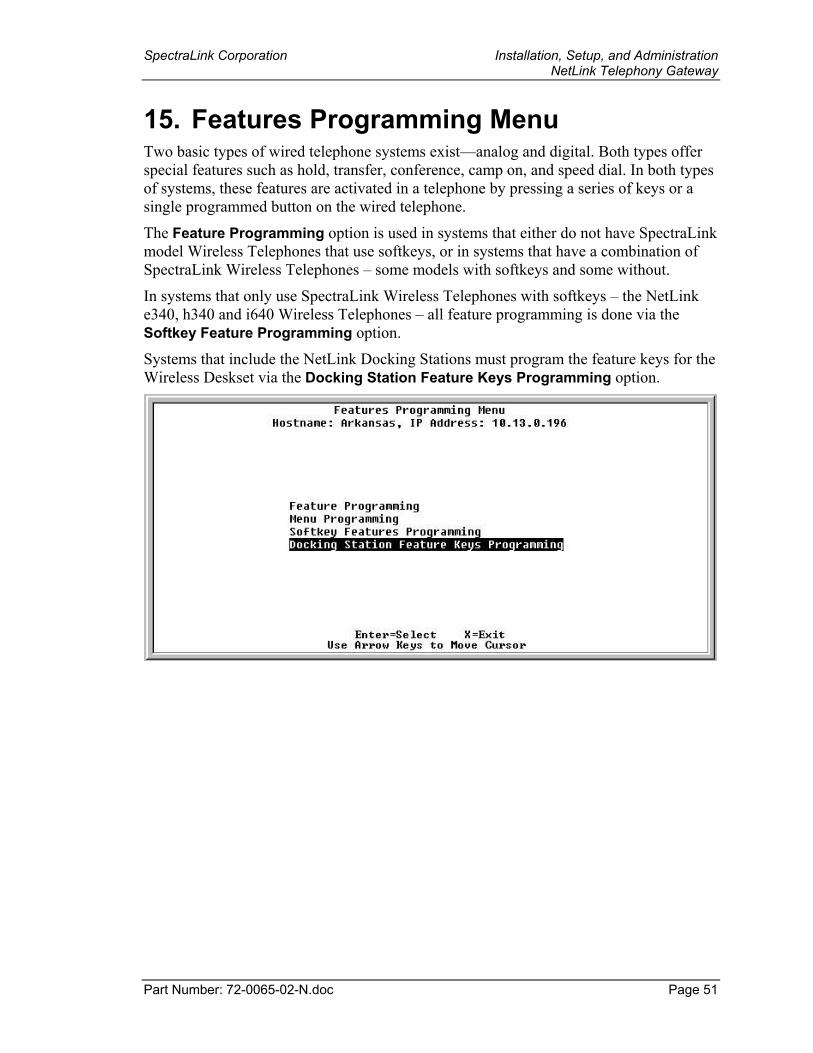
SpectraLink Corporation Installation, Setup, and Administration NetLink Telephony Gateway
Part Number: 72-0065-02-N.doc Page 51
15. Features Programming Menu Two basic types of wired telephone systems exist—analog and digital. Both types offer special features such as hold, transfer, conference, camp on, and speed dial. In both types of systems, these features are activated in a telephone by pressing a series of keys or a single programmed button on the wired telephone.
The Feature Programming option is used in systems that either do not have SpectraLink model Wireless Telephones that use softkeys, or in systems that have a combination of SpectraLink Wireless Telephones – some models with softkeys and some without.
In systems that only use SpectraLink Wireless Telephones with softkeys – the NetLink e340, h340 and i640 Wireless Telephones – all feature programming is done via the Softkey Feature Programming option.
Systems that include the NetLink Docking Stations must program the feature keys for the Wireless Deskset via the Docking Station Feature Keys Programming option.
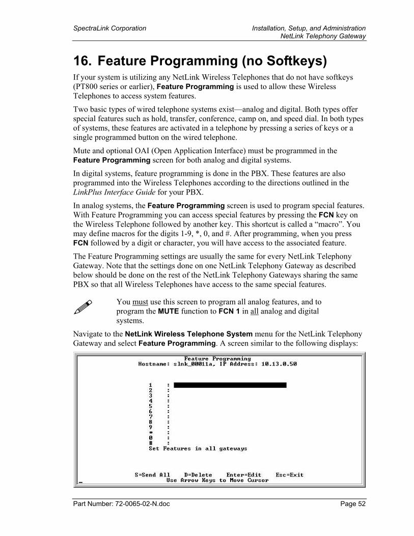
SpectraLink Corporation Installation, Setup, and Administration NetLink Telephony Gateway
Part Number: 72-0065-02-N.doc Page 52
16. Feature Programming (no Softkeys) If your system is utilizing any NetLink Wireless Telephones that do not have softkeys (PT800 series or earlier), Feature Programming is used to allow these Wireless Telephones to access system features.
Two basic types of wired telephone systems exist—analog and digital. Both types offer special features such as hold, transfer, conference, camp on, and speed dial. In both types of systems, these features are activated in a telephone by pressing a series of keys or a single programmed button on the wired telephone.
Mute and optional OAI (Open Application Interface) must be programmed in the Feature Programming screen for both analog and digital systems.
In digital systems, feature programming is done in the PBX. These features are also programmed into the Wireless Telephones according to the directions outlined in the LinkPlus Interface Guide for your PBX.
In analog systems, the Feature Programming screen is used to program special features. With Feature Programming you can access special features by pressing the FCN key on the Wireless Telephone followed by another key. This shortcut is called a “macro”. You may define macros for the digits 1-9, *, 0, and #. After programming, when you press FCN followed by a digit or character, you will have access to the associated feature.
The Feature Programming settings are usually the same for every NetLink Telephony Gateway. Note that the settings done on one NetLink Telephony Gateway as described below should be done on the rest of the NetLink Telephony Gateways sharing the same PBX so that all Wireless Telephones have access to the same special features.
You must use this screen to program all analog features, and to program the MUTE function to FCN 1 in all analog and digital systems.
Navigate to the NetLink Wireless Telephone System menu for the NetLink Telephony Gateway and select Feature Programming. A screen similar to the following displays:
SpectraLink Corporation Installation, Setup, and Administration NetLink Telephony Gateway
Part Number: 72-0065-02-N.doc Page 53
16.1. Programming Digital PBX Features The numbers and symbols along the left side of the screen indicate which number or digit key is being pressed after the FCN key to activate the feature.
1. Navigate to key 1 and type MUTE.
2. If a NetLink OAI Gateway is part of the system, navigate to the key the OAI function is to be assigned to and type OAI.
3. See below for programming the ADMIN feature.
All other digital features are programmed in the PBX per the Digital Interface Guide for your system.
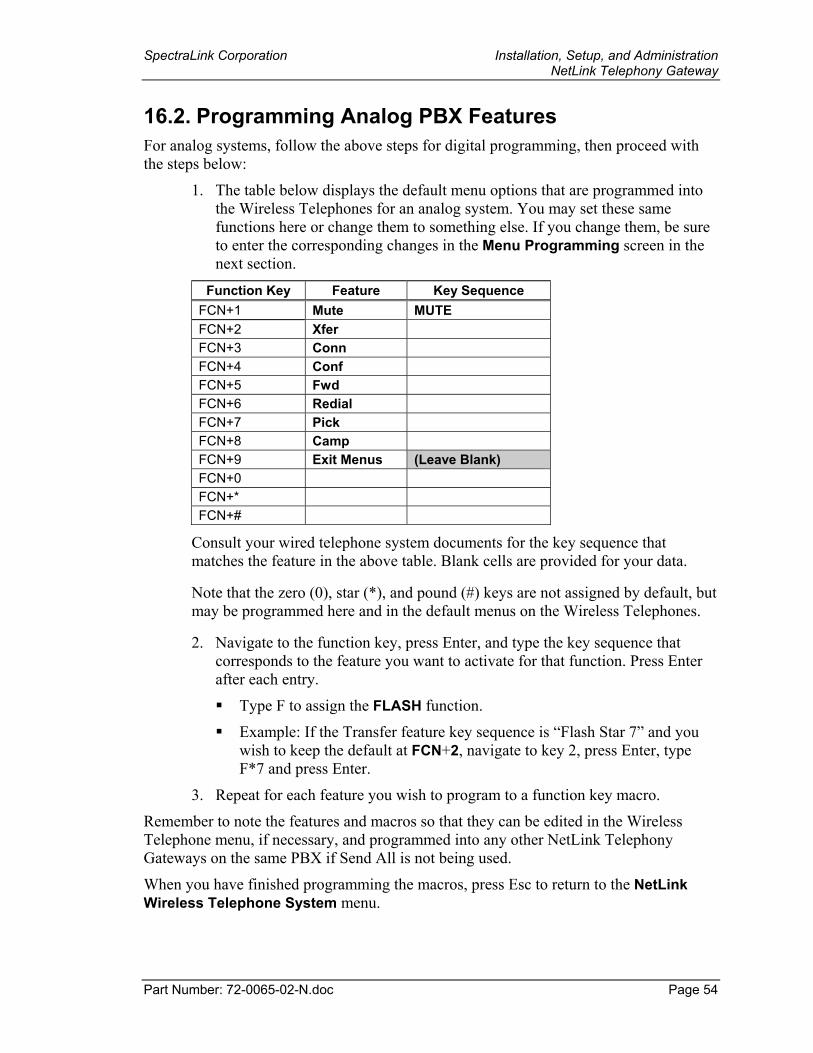
SpectraLink Corporation Installation, Setup, and Administration NetLink Telephony Gateway
Part Number: 72-0065-02-N.doc Page 54
16.2. Programming Analog PBX Features For analog systems, follow the above steps for digital programming, then proceed with the steps below:
1. The table below displays the default menu options that are programmed into the Wireless Telephones for an analog system. You may set these same functions here or change them to something else. If you change them, be sure to enter the corresponding changes in the Menu Programming screen in the next section.
Function Key Feature Key Sequence FCN+1 Mute MUTE FCN+2 Xfer FCN+3 Conn FCN+4 Conf FCN+5 Fwd FCN+6 Redial FCN+7 Pick FCN+8 Camp FCN+9 Exit Menus (Leave Blank) FCN+0 FCN+* FCN+#
Consult your wired telephone system documents for the key sequence that matches the feature in the above table. Blank cells are provided for your data.
Note that the zero (0), star (*), and pound (#) keys are not assigned by default, but may be programmed here and in the default menus on the Wireless Telephones.
2. Navigate to the function key, press Enter, and type the key sequence that corresponds to the feature you want to activate for that function. Press Enter after each entry.
Type F to assign the FLASH function.
Example: If the Transfer feature key sequence is “Flash Star 7” and you wish to keep the default at FCN+2, navigate to key 2, press Enter, type F*7 and press Enter.
3. Repeat for each feature you wish to program to a function key macro.
Remember to note the features and macros so that they can be edited in the Wireless Telephone menu, if necessary, and programmed into any other NetLink Telephony Gateways on the same PBX if Send All is not being used.
When you have finished programming the macros, press Esc to return to the NetLink Wireless Telephone System menu.
SpectraLink Corporation Installation, Setup, and Administration NetLink Telephony Gateway
Part Number: 72-0065-02-N.doc Page 55
16.3. Programming the ADMIN Feature The ADMIN option allows the system administrator to add and delete Wireless Telephones via another Wireless Telephone, rather than via the NetLink Telephony Gateway. Any function key sequence may be programmed to ADMIN by typing ADMIN next to the desired key. The ADMIN feature may be programmed on only one NetLink Telephony Gateway (the one that contains the line used by the system administrator) in order to limit its accessibility system-wide.
When the ADMIN function is active, pressing the function key sequence on the Wireless Telephone will open the ADMIN function. The following steps allow the administrator to add or delete a Wireless Telephone:
1. Press FCN plus the assigned key. Once in the ADMIN function, pressing the FCN key will cancel the action and return to the previous menu level.
2. Enter the NetLink Telephony Gateway password using the Wireless Telephone keypad. Note that the password is case sensitive. The key steps through each letter and number as it is repetitively pressed.
3. Once the password is accepted, the NetLink Telephony Gateways are listed. Use the arrow keys to scroll through the list. Press 0 (the zero key) to select the correct NetLink Telephony Gateway.
4. The Wireless Telephones assigned to the selected NetLink Telephony Gateway are listed by the last three byte numbers in the MAC address. If a line is not assigned to a Wireless Telephone, not used will display. Use the arrow keys to scroll through the lines.
5. Display the line to add or delete a Wireless Telephone and follow the prompts displayed on the Wireless Telephone.
6. If a name or extension must be associated with an added Wireless Telephone for record keeping purposes, it must be entered on the NetLink Telephony Gateway Telephone Line Configuration screen.
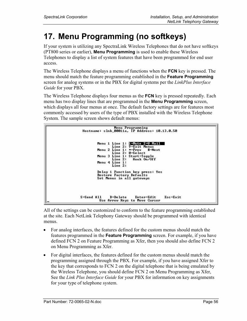
SpectraLink Corporation Installation, Setup, and Administration NetLink Telephony Gateway
Part Number: 72-0065-02-N.doc Page 56
17. Menu Programming (no softkeys) If your system is utilizing any SpectraLink Wireless Telephones that do not have softkeys (PT800 series or earlier), Menu Programming is used to enable these Wireless Telephones to display a list of system features that have been programmed for end user access.
The Wireless Telephone displays a menu of functions when the FCN key is pressed. The menu should match the feature programming established in the Feature Programming screen for analog systems or in the PBX for digital systems per the LinkPlus Interface Guide for your PBX.
The Wireless Telephone displays four menus as the FCN key is pressed repeatedly. Each menu has two display lines that are programmed in the Menu Programming screen, which displays all four menus at once. The default factory settings are for features most commonly accessed by users of the type of PBX installed with the Wireless Telephone System. The sample screen shows default menus:
All of the settings can be customized to conform to the feature programming established at the site. Each NetLink Telephony Gateway should be programmed with identical menus.
• For analog interfaces, the features defined for the custom menus should match the features programmed in the Feature Programming screen. For example, if you have defined FCN 2 on Feature Programming as Xfer, then you should also define FCN 2 on Menu Programming as Xfer.
• For digital interfaces, the features defined for the custom menus should match the programming assigned through the PBX. For example, if you have assigned Xfer to the key that corresponds to FCN 2 on the digital telephone that is being emulated by the Wireless Telephone, you should define FCN 2 on Menu Programming as Xfer, See the Link Plus Interface Guide for your PBX for information on key assignments for your type of telephone system.
SpectraLink Corporation Installation, Setup, and Administration NetLink Telephony Gateway
Part Number: 72-0065-02-N.doc Page 57
Note that some key assignments cannot be customized on certain types of telephone systems.
Navigate to the NetLink Wireless Telephone System menu for the NetLink Telephony Gateway and select Menu Programming. The screen will display the defaults for your system.
Each of the four menus displays two lines. The numbers followed by the equal sign indicate which key to press on the Wireless Telephone to activate the feature, such as 2=Xfer (Transfer). These lines will display on the Wireless Telephone exactly as programmed here. All NetLink Telephony Gateways should be programmed identically.
If any of the factory defaults have been changed via Feature Programming or in the steps outlined in the LinkPlus Interface Guide for your PBX, the menu items here should be changed so that they correspond to what has been programmed elsewhere.
The Delay function is utilized when the PBX uses softkeys. With Delay, when the FCN key is pressed, the Wireless Telephone displays the features that are associated with the softkeys so that one of these features can be selected first. If Delay is programmed, pressing FCN twice will bring up the programmed menus immediately.
Restore Factory Defaults allows you to reset the menus. See the LinkPlus Interface Guide for your PBX for the default menus programmed by SpectraLink.
To change the menu settings: 1. Navigate to the menu display screen number (1-4) to be edited.
2. Press Enter to change the information, then enter the information to be displayed on each line of the menu.
3. Press Enter to save the entries.
4. Repeat for each menu as needed.
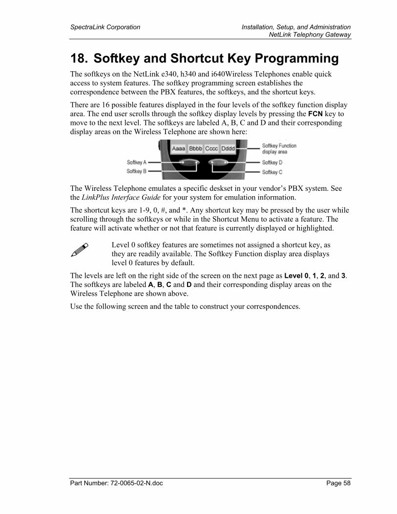
SpectraLink Corporation Installation, Setup, and Administration NetLink Telephony Gateway
Part Number: 72-0065-02-N.doc Page 58
18. Softkey and Shortcut Key Programming The softkeys on the NetLink e340, h340 and i640Wireless Telephones enable quick access to system features. The softkey programming screen establishes the correspondence between the PBX features, the softkeys, and the shortcut keys.
There are 16 possible features displayed in the four levels of the softkey function display area. The end user scrolls through the softkey display levels by pressing the FCN key to move to the next level. The softkeys are labeled A, B, C and D and their corresponding display areas on the Wireless Telephone are shown here:
The Wireless Telephone emulates a specific deskset in your vendor’s PBX system. See the LinkPlus Interface Guide for your system for emulation information.
The shortcut keys are 1-9, 0, #, and *. Any shortcut key may be pressed by the user while scrolling through the softkeys or while in the Shortcut Menu to activate a feature. The feature will activate whether or not that feature is currently displayed or highlighted.
Level 0 softkey features are sometimes not assigned a shortcut key, as they are readily available. The Softkey Function display area displays level 0 features by default.
The levels are left on the right side of the screen on the next page as Level 0, 1, 2, and 3. The softkeys are labeled A, B, C and D and their corresponding display areas on the Wireless Telephone are shown above.
Use the following screen and the table to construct your correspondences.
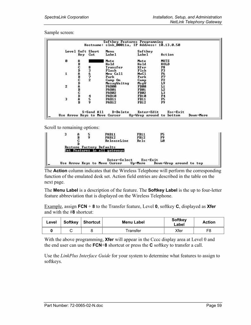
SpectraLink Corporation Installation, Setup, and Administration NetLink Telephony Gateway
Part Number: 72-0065-02-N.doc Page 59
Sample screen:
Scroll to remaining options:
The Action column indicates that the Wireless Telephone will perform the corresponding function of the emulated desk set. Action field entries are described in the table on the next page.
The Menu Label is a description of the feature. The Softkey Label is the up to four-letter feature abbreviation that is displayed on the Wireless Telephone.
Example, assign FCN + 8 to the Transfer feature, Level 0, softkey C, displayed as Xfer and with the #8 shortcut:
Level Softkey Shortcut Menu Label Softkey Label Action
0 C 8 Transfer Xfer F8
With the above programming, Xfer will appear in the Cccc display area at Level 0 and the end user can use the FCN+8 shortcut or press the C softkey to transfer a call.
Use the LinkPlus Interface Guide for your system to determine what features to assign to softkeys.
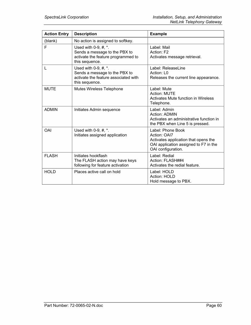
SpectraLink Corporation Installation, Setup, and Administration NetLink Telephony Gateway
Part Number: 72-0065-02-N.doc Page 60
Action Entry Description Example (blank) No action is assigned to softkey. F Used with 0-9, #, *.
Sends a message to the PBX to activate the feature programmed to this sequence.
Label: Mail Action: F2 Activates message retrieval.
L Used with 0-9, #, *. Sends a message to the PBX to activate the feature associated with this sequence.
Label: ReleaseLine Action: L0 Releases the current line appearance.
MUTE Mutes Wireless Telephone Label: Mute Action: MUTE Activates Mute function in Wireless Telephone.
ADMIN Initiates Admin sequence Label: Admin Action: ADMIN Activates an administrative function in the PBX when Line 5 is pressed.
OAI Used with 0-9, #, *. Initiates assigned application
Label: Phone Book Action: OAI7 Activates application that opens the OAI application assigned to F7 in the OAI configuration.
FLASH Initiates hookflash The FLASH action may have keys following for feature activation
Label: Redial Action: FLASH##4 Activates the redial feature.
HOLD Places active call on hold Label: HOLD Action: HOLD Hold message to PBX.
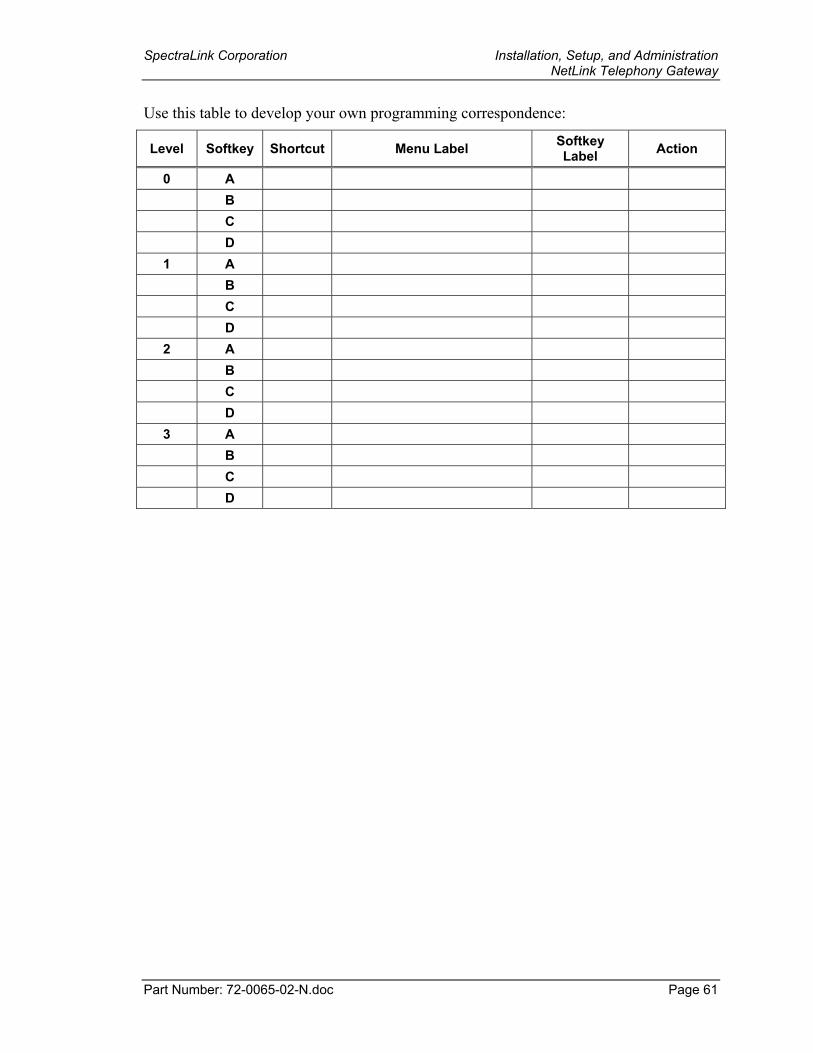
SpectraLink Corporation Installation, Setup, and Administration NetLink Telephony Gateway
Part Number: 72-0065-02-N.doc Page 61
Use this table to develop your own programming correspondence:
Level Softkey Shortcut Menu Label Softkey Label Action
0 A B C D 1 A B C D 2 A B C D 3 A B C D
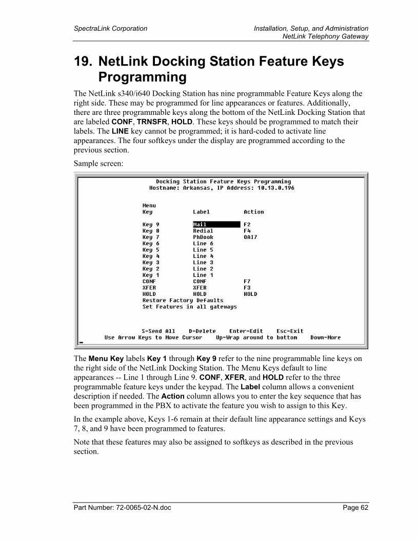
SpectraLink Corporation Installation, Setup, and Administration NetLink Telephony Gateway
Part Number: 72-0065-02-N.doc Page 62
19. NetLink Docking Station Feature Keys Programming
The NetLink s340/i640 Docking Station has nine programmable Feature Keys along the right side. These may be programmed for line appearances or features. Additionally, there are three programmable keys along the bottom of the NetLink Docking Station that are labeled CONF, TRNSFR, HOLD. These keys should be programmed to match their labels. The LINE key cannot be programmed; it is hard-coded to activate line appearances. The four softkeys under the display are programmed according to the previous section.
Sample screen:
The Menu Key labels Key 1 through Key 9 refer to the nine programmable line keys on the right side of the NetLink Docking Station. The Menu Keys default to line appearances -- Line 1 through Line 9. CONF, XFER, and HOLD refer to the three programmable feature keys under the keypad. The Label column allows a convenient description if needed. The Action column allows you to enter the key sequence that has been programmed in the PBX to activate the feature you wish to assign to this Key.
In the example above, Keys 1-6 remain at their default line appearance settings and Keys 7, 8, and 9 have been programmed to features.
Note that these features may also be assigned to softkeys as described in the previous section.
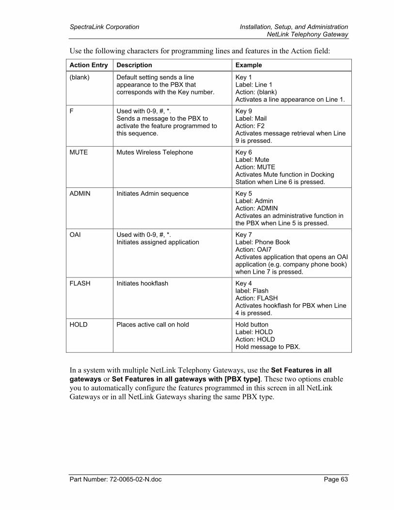
SpectraLink Corporation Installation, Setup, and Administration NetLink Telephony Gateway
Part Number: 72-0065-02-N.doc Page 63
Use the following characters for programming lines and features in the Action field:
Action Entry Description Example
(blank) Default setting sends a line appearance to the PBX that corresponds with the Key number.
Key 1 Label: Line 1 Action: (blank) Activates a line appearance on Line 1.
F Used with 0-9, #, *. Sends a message to the PBX to activate the feature programmed to this sequence.
Key 9 Label: Mail Action: F2 Activates message retrieval when Line 9 is pressed.
MUTE Mutes Wireless Telephone Key 6 Label: Mute Action: MUTE Activates Mute function in Docking Station when Line 6 is pressed.
ADMIN Initiates Admin sequence Key 5 Label: Admin Action: ADMIN Activates an administrative function in the PBX when Line 5 is pressed.
OAI Used with 0-9, #, *. Initiates assigned application
Key 7 Label: Phone Book Action: OAI7 Activates application that opens an OAI application (e.g. company phone book) when Line 7 is pressed.
FLASH Initiates hookflash Key 4 label: Flash Action: FLASH Activates hookflash for PBX when Line 4 is pressed.
HOLD Places active call on hold Hold button Label: HOLD Action: HOLD Hold message to PBX.
In a system with multiple NetLink Telephony Gateways, use the Set Features in all gateways or Set Features in all gateways with [PBX type]. These two options enable you to automatically configure the features programmed in this screen in all NetLink Gateways or in all NetLink Gateways sharing the same PBX type.
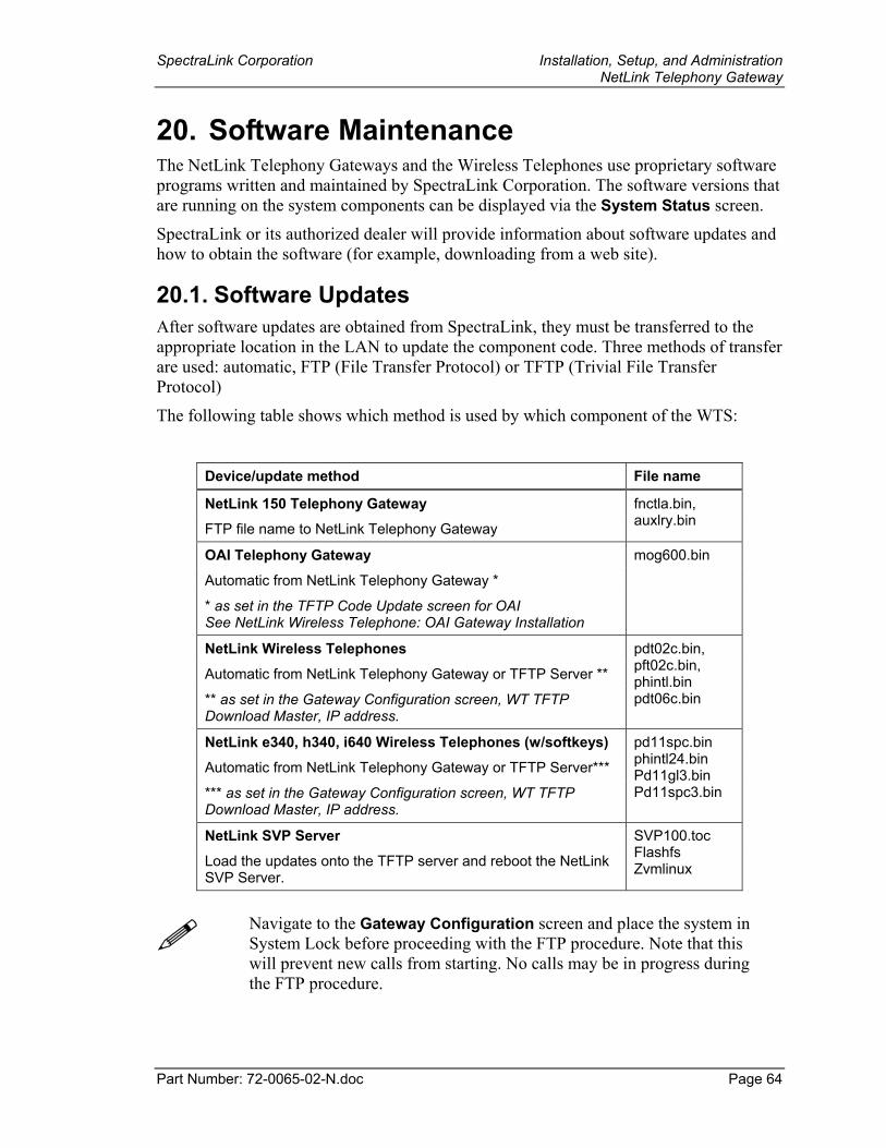
SpectraLink Corporation Installation, Setup, and Administration NetLink Telephony Gateway
Part Number: 72-0065-02-N.doc Page 64
20. Software Maintenance The NetLink Telephony Gateways and the Wireless Telephones use proprietary software programs written and maintained by SpectraLink Corporation. The software versions that are running on the system components can be displayed via the System Status screen.
SpectraLink or its authorized dealer will provide information about software updates and how to obtain the software (for example, downloading from a web site).
20.1. Software Updates After software updates are obtained from SpectraLink, they must be transferred to the appropriate location in the LAN to update the component code. Three methods of transfer are used: automatic, FTP (File Transfer Protocol) or TFTP (Trivial File Transfer Protocol)
The following table shows which method is used by which component of the WTS:
Device/update method File name
NetLink 150 Telephony Gateway FTP file name to NetLink Telephony Gateway
fnctla.bin, auxlry.bin
OAI Telephony Gateway mog600.bin
Automatic from NetLink Telephony Gateway *
* as set in the TFTP Code Update screen for OAI See NetLink Wireless Telephone: OAI Gateway Installation
NetLink Wireless Telephones Automatic from NetLink Telephony Gateway or TFTP Server **
** as set in the Gateway Configuration screen, WT TFTP Download Master, IP address.
pdt02c.bin, pft02c.bin, phintl.bin pdt06c.bin
NetLink e340, h340, i640 Wireless Telephones (w/softkeys) Automatic from NetLink Telephony Gateway or TFTP Server***
*** as set in the Gateway Configuration screen, WT TFTP Download Master, IP address.
pd11spc.bin phintl24.bin Pd11gl3.bin Pd11spc3.bin
NetLink SVP Server Load the updates onto the TFTP server and reboot the NetLink SVP Server.
SVP100.toc Flashfs Zvmlinux
Navigate to the Gateway Configuration screen and place the system in System Lock before proceeding with the FTP procedure. Note that this will prevent new calls from starting. No calls may be in progress during the FTP procedure.
SpectraLink Corporation Installation, Setup, and Administration NetLink Telephony Gateway
Part Number: 72-0065-02-N.doc Page 65
FTP Procedure When using FTP, use a host system to connect to a remote system. In this example, the host is the client and the server is the Telephony Gateway. The “put” command means to copy the files from the host to the remote system. The “get” command means to copy the files from the remote system to the host.
Note that FTP commands vary with the program being used. Use the following steps as a general guide but be aware that your FTP program may use different terms to describe the procedure.
Note: You MUST delete unneeded Wireless Telephone image files on the NetLink Telephony Gateway to create needed space for newer software. FTP programs differ in how this is done but generally allow you to delete files in the host and client location.
To transfer the software using FTP:
1. Connect to the Telephony Gateway using the command: FTP <hostname> or FTP <IP address>.
2. Log in using the administrator login (“admin”) and password (default is “admin”). A login confirmation message will display, followed by the FTP> prompt.
3. At the FTP prompt, type binary. A confirmation message will display. At the FTP prompt, type Hash. File transfer progress will be displayed during the transfer.
4. At the FTP prompt, use the Put command to transfer the required files to the client server or Telephony Gateway.
5. After files are transferred, use the Quit command to quit FTP.
6. Navigate to the main menu for the Telephony Gateway and select System Status. Then select Software Versions to verify that software versions for the Telephony Gateway are correct.
7. Reset the system via the Gateway Configuration screen in order to restore Maintenance Lock to No.
Note: For all systems with multiple NetLink Telephony Gateways, ALL upgradeable software files must match exactly (be the same version).
Note: A graphical user interface FTP client may be utilized in lieu of the aforementioned command line FTP procedure.
SpectraLink Corporation Installation, Setup, and Administration NetLink Telephony Gateway
Part Number: 72-0065-02-N.doc Page 66
20.2. Upgrading Wireless Telephones NetLink allows over-the-air transfer of software updates from the NetLink Telephony Gateway or designated TFTP server to the Wireless Telephones.
The downloader function in the Wireless Telephone checks its software version every time the Wireless Telephone is turned on. If there is any discrepancy in the functional code (pdt02c.bin or pft02c.bin or pd11spc.bin or pdt06c.bin) or the image (phintl.bin or phintl24.bin) the Wireless Telephone immediately begins to download the update
You may use the Checkout all phones option in the Gateway Configuration menu to update all Wireless Telephones. If the TFTP server is on a PC, this command may be used to upgrade each Wireless Telephone without having to reset the Gateway. This command forces all the Wireless Telephones on the system to check in with the Gateway. They will check their current software version against the version stored on the TFTP server and download if needed. Any Wireless Telephones in a call will perform their checkout after the call has been completed.
Normal Download Messages When the Wireless Telephone is powered on, it displays a series of messages indicating that it is searching for new software, checking the versions, and downloading. The normal message progression is:
Message Description Checking Code Wireless Telephone is contacting the Download Master to determine if it has a
newer version of software that should be downloaded.
Erasing Memory Wireless Telephone has determined that a download should occur and is erasing the current software from memory. This message also displays a progress bar. When the progress bar fills the display line the erase operation is complete.
Updating Code Wireless Telephone is downloading new software into memory. The number icons at the bottom of the display indicate which file number is currently being downloaded. This message also displays a progress bar. When the progress bar fills the display line the update operation is complete on that file.
While the Wireless Telephone is updating, the NO SVC message displays, and the Wireless Telephone should NOT be powered off.
When the update is complete, the Wireless Telephone displays the extension number, and is ready for use.
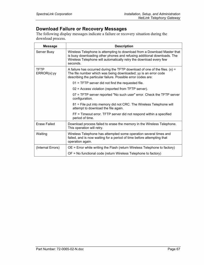
SpectraLink Corporation Installation, Setup, and Administration NetLink Telephony Gateway
Part Number: 72-0065-02-N.doc Page 67
Download Failure or Recovery Messages The following display messages indicate a failure or recovery situation during the download process.
Message Description Server Busy Wireless Telephone is attempting to download from a Download Master that
is busy downloading other phones and refusing additional downloads. The Wireless Telephone will automatically retry the download every few seconds.
TFTP ERROR(x):yy
A failure has occurred during the TFTP download of one of the files. (x) = The file number which was being downloaded; yy is an error code describing the particular failure. Possible error codes are:
01 = TFTP server did not find the requested file.
02 = Access violation (reported from TFTP server).
07 = TFTP server reported "No such user" error. Check the TFTP server configuration.
81 = File put into memory did not CRC. The Wireless Telephone will attempt to download the file again.
FF = Timeout error. TFTP server did not respond within a specified period of time.
Erase Failed Download process failed to erase the memory in the Wireless Telephone. This operation will retry.
Waiting Wireless Telephone has attempted some operation several times and failed, and is now waiting for a period of time before attempting that operation again.
(Internal Errors) OE = Error while writing the Flash (return Wireless Telephone to factory)
OF = No functional code (return Wireless Telephone to factory)
SpectraLink Corporation Installation, Setup, and Administration NetLink Telephony Gateway
Part Number: 72-0065-02-N.doc Page 68
20.3. Backup and Restore NetLink Telephony Gateway Configuration
Proper software maintenance activities include backing up the system to safeguard the configuration of the NetLink Telephony Gateway. FTP is used to copy the Gateway configuration (filename config.bin) from the NetLink Telephony Gateway for backup purposes. The files can then be restored to the system as needed, also using FTP.
The following is an example of software transfer using FTP. FTP commands may vary depending on your FTP program.
To copy the configuration from/to the NetLink Telephony Gateway:
1. Connect to the NetLink Telephony Gateway.
2. Log in using the administrator login and password. A login confirm message will display, followed by the FTP> prompt.
3. At the FTP prompt, type binary. A confirm message will display.
4. Use Get to backup the files and Put to restore files.
Backup: At the FTP prompt, use the get command to transfer the required files from the NetLink Telephony Gateway to the server: get config.bin. Restore: At the FTP prompt, use the put command to transfer the required files from the server to the NetLink Telephony Gateway: put config.bin.
The get and put commands will copy files. Be careful not to overwrite your config.bin files. To avoid this, you can:
Change directories before you connect and copy each Gateway’s config.bin file to its own directory.
Use the local file name form of the get (or put) command to rename the file when it is copied. For example, get config.bin gateway1.bin copies config.bin as gateway1.bin to the host.
Remember to copy the correct files when restoring configuration files. For example put gateway1.bin config.bin copies gateway1.bin as config.bin to the Telephony Gateway.
5. After files are transferred, use the Quit command to quit FTP.
6. Reset the system via the Gateway Configuration screen in order to restore Maintenance Lock to No.
7. Navigate to the Gateway Configuration and Telephone Line Configuration screens to ensure all configuration information has been restored.
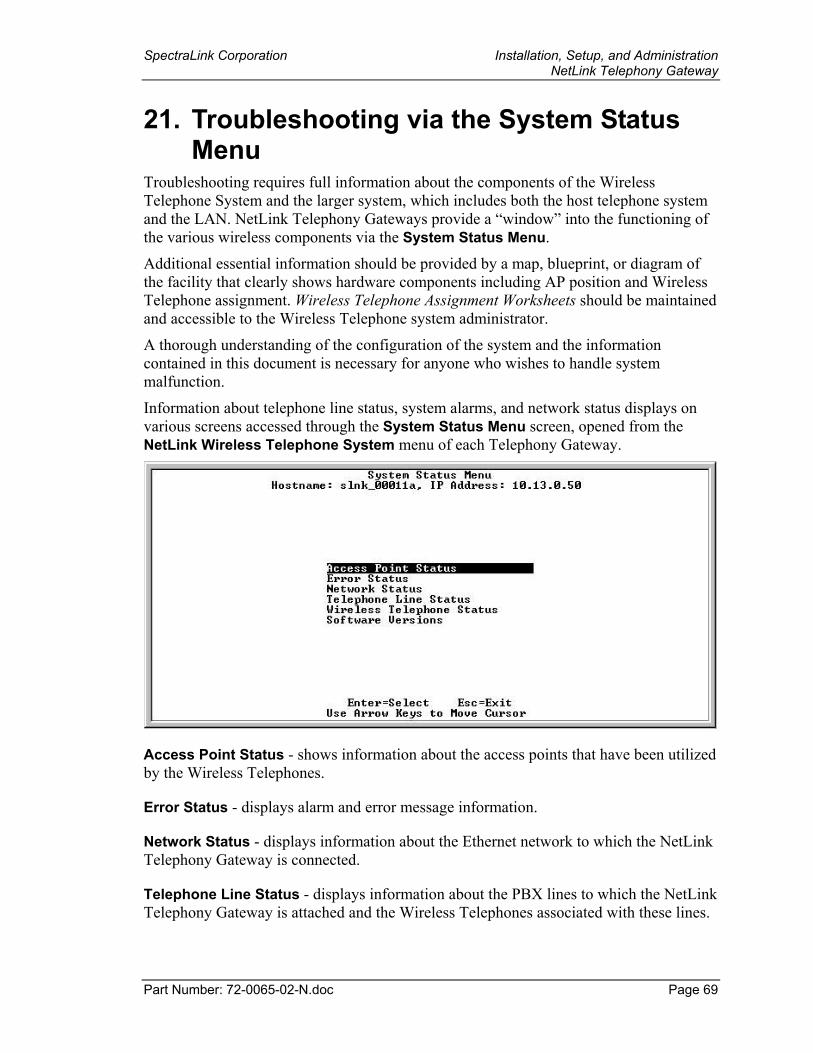
SpectraLink Corporation Installation, Setup, and Administration NetLink Telephony Gateway
Part Number: 72-0065-02-N.doc Page 69
21. Troubleshooting via the System Status Menu
Troubleshooting requires full information about the components of the Wireless Telephone System and the larger system, which includes both the host telephone system and the LAN. NetLink Telephony Gateways provide a “window” into the functioning of the various wireless components via the System Status Menu.
Additional essential information should be provided by a map, blueprint, or diagram of the facility that clearly shows hardware components including AP position and Wireless Telephone assignment. Wireless Telephone Assignment Worksheets should be maintained and accessible to the Wireless Telephone system administrator.
A thorough understanding of the configuration of the system and the information contained in this document is necessary for anyone who wishes to handle system malfunction.
Information about telephone line status, system alarms, and network status displays on various screens accessed through the System Status Menu screen, opened from the NetLink Wireless Telephone System menu of each Telephony Gateway.
Access Point Status - shows information about the access points that have been utilized by the Wireless Telephones.
Error Status - displays alarm and error message information.
Network Status - displays information about the Ethernet network to which the NetLink Telephony Gateway is connected.
Telephone Line Status - displays information about the PBX lines to which the NetLink Telephony Gateway is attached and the Wireless Telephones associated with these lines.
SpectraLink Corporation Installation, Setup, and Administration NetLink Telephony Gateway
Part Number: 72-0065-02-N.doc Page 70
Wireless Telephone Status - contains network communications statistics for each Wireless Telephone.
Software Versions - lists the software version for each component in the SpectraLink Wireless Telephone System.
Options on the System Status Menu provide a window into the real time operation of the components of the a NetLink Wireless Telephone System. Use this data to determine system function and to troubleshoot areas that may be experiencing trouble.
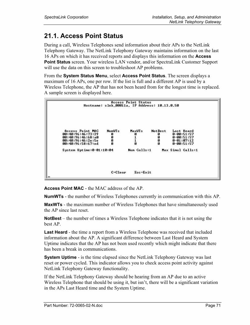
SpectraLink Corporation Installation, Setup, and Administration NetLink Telephony Gateway
Part Number: 72-0065-02-N.doc Page 71
21.1. Access Point Status During a call, Wireless Telephones send information about their APs to the NetLink Telephony Gateway. The NetLink Telephony Gateway maintains information on the last 16 APs on which it has received reports and displays this information on the Access Point Status screen. Your wireless LAN vendor, and/or SpectraLink Customer Support will use the data on this screen to troubleshoot AP problems.
From the System Status Menu, select Access Point Status. The screen displays a maximum of 16 APs, one per row. If the list is full and a different AP is used by a Wireless Telephone, the AP that has not been heard from for the longest time is replaced. A sample screen is displayed here.
Access Point MAC - the MAC address of the AP.
NumWTs - the number of Wireless Telephones currently in communication with this AP.
MaxWTs - the maximum number of Wireless Telephones that have simultaneously used the AP since last reset.
NotBest – the number of times a Wireless Telephone indicates that it is not using the best AP.
Last Heard - the time a report from a Wireless Telephone was received that included information about the AP. A significant difference between Last Heard and System Uptime indicates that the AP has not been used recently which might indicate that there has been a break in communications.
System Uptime - is the time elapsed since the NetLink Telephony Gateway was last reset or power cycled. This indicator allows you to check access point activity against NetLink Telephony Gateway functionality.
If the NetLink Telephony Gateway should be hearing from an AP due to an active Wireless Telephone that should be using it, but isn’t, there will be a significant variation in the APs Last Heard time and the System Uptime.
SpectraLink Corporation Installation, Setup, and Administration NetLink Telephony Gateway
Part Number: 72-0065-02-N.doc Page 72
Clear Status - Clearing the statistics sets Num WTS, Max WTS, and Not Best to zero. It does not remove any APs from the displayed array. The Clear Status function allows you start over and view AP activity from that point in time.
Unless noted otherwise, times are displayed using the format: D - HH : MM : SS D is day, HH is hours, MM is minutes, and SS is seconds.
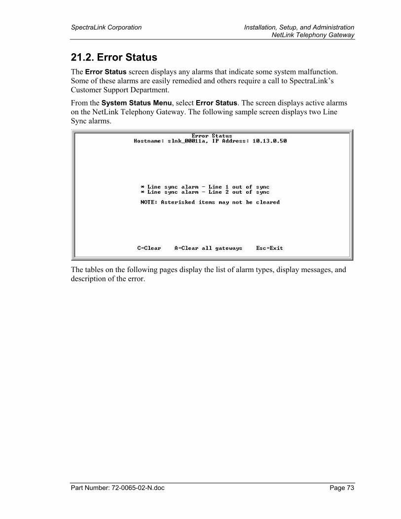
SpectraLink Corporation Installation, Setup, and Administration NetLink Telephony Gateway
Part Number: 72-0065-02-N.doc Page 73
21.2. Error Status The Error Status screen displays any alarms that indicate some system malfunction. Some of these alarms are easily remedied and others require a call to SpectraLink’s Customer Support Department.
From the System Status Menu, select Error Status. The screen displays active alarms on the NetLink Telephony Gateway. The following sample screen displays two Line Sync alarms.
The tables on the following pages display the list of alarm types, display messages, and description of the error.
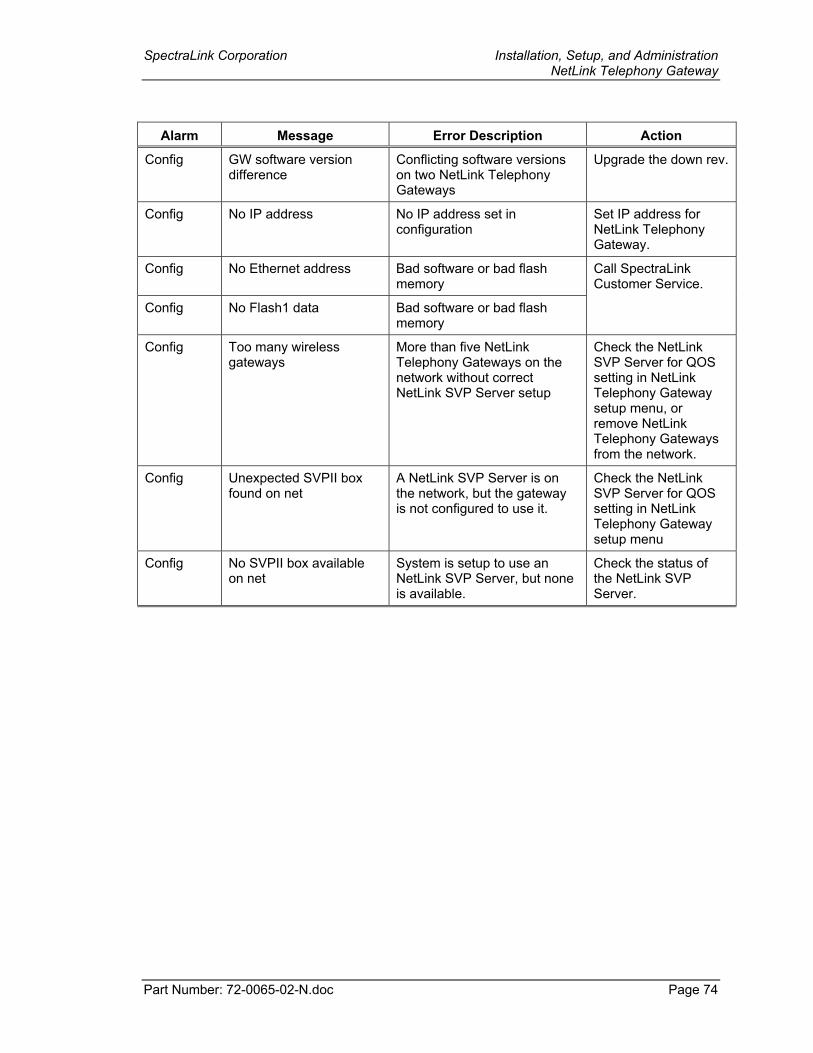
SpectraLink Corporation Installation, Setup, and Administration NetLink Telephony Gateway
Part Number: 72-0065-02-N.doc Page 74
Alarm Message Error Description Action
Config GW software version difference
Conflicting software versions on two NetLink Telephony Gateways
Upgrade the down rev.
Config No IP address No IP address set in configuration
Set IP address for NetLink Telephony Gateway.
Config No Ethernet address Bad software or bad flash memory
Call SpectraLink Customer Service.
Config No Flash1 data Bad software or bad flash memory
Config Too many wireless gateways
More than five NetLink Telephony Gateways on the network without correct NetLink SVP Server setup
Check the NetLink SVP Server for QOS setting in NetLink Telephony Gateway setup menu, or remove NetLink Telephony Gateways from the network.
Config Unexpected SVPII box found on net
A NetLink SVP Server is on the network, but the gateway is not configured to use it.
Check the NetLink SVP Server for QOS setting in NetLink Telephony Gateway setup menu
Config No SVPII box available on net
System is setup to use an NetLink SVP Server, but none is available.
Check the status of the NetLink SVP Server.
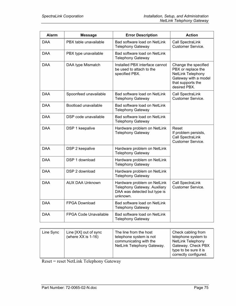
SpectraLink Corporation Installation, Setup, and Administration NetLink Telephony Gateway
Part Number: 72-0065-02-N.doc Page 75
Alarm Message Error Description Action
DAA PBX table unavailable Bad software load on NetLink Telephony Gateway
Call SpectraLink Customer Service.
DAA PBX type unavailable Bad software load on NetLink Telephony Gateway
DAA DAA type Mismatch Installed PBX interface cannot be used to attach to the specified PBX.
Change the specified PBX or replace the NetLink Telephony Gateway with a model that supports the desired PBX.
DAA Spoonfeed unavailable Bad software load on NetLink Telephony Gateway
Call SpectraLink Customer Service.
DAA Bootload unavailable Bad software load on NetLink Telephony Gateway
DAA DSP code unavailable Bad software load on NetLink Telephony Gateway
DAA DSP 1 keepalive Hardware problem on NetLink Telephony Gateway
Reset If problem persists, Call SpectraLink Customer Service.
DAA DSP 2 keepalive Hardware problem on NetLink Telephony Gateway
DAA DSP 1 download Hardware problem on NetLink Telephony Gateway
DAA DSP 2 download Hardware problem on NetLink Telephony Gateway
DAA AUX DAA Unknown Hardware problem on NetLink Telephony Gateway. Auxiliary DAA was detected but type is unknown.
Call SpectraLink Customer Service.
DAA FPGA Download Bad software load on NetLink Telephony Gateway
DAA FPGA Code Unavailable Bad software load on NetLink Telephony Gateway
Line Sync Line [XX] out of sync (where XX is 1-16)
The line from the host telephone system is not communicating with the NetLink Telephony Gateway.
Check cabling from telephone system to NetLink Telephony Gateway. Check PBX type to be sure it is correctly configured.
Reset = reset NetLink Telephony Gateway
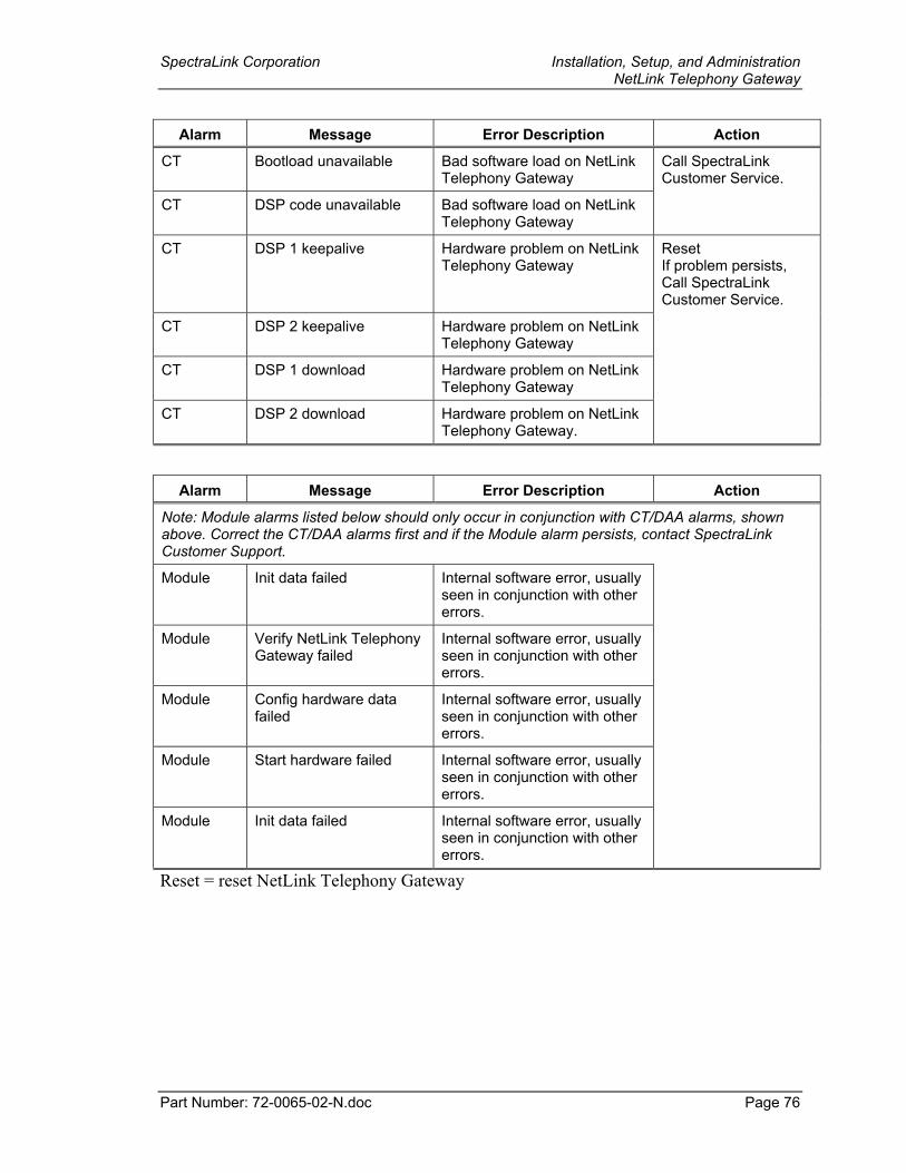
SpectraLink Corporation Installation, Setup, and Administration NetLink Telephony Gateway
Part Number: 72-0065-02-N.doc Page 76
Alarm Message Error Description Action
CT Bootload unavailable Bad software load on NetLink Telephony Gateway
Call SpectraLink Customer Service.
CT DSP code unavailable Bad software load on NetLink Telephony Gateway
CT DSP 1 keepalive Hardware problem on NetLink Telephony Gateway
Reset If problem persists, Call SpectraLink Customer Service.
CT DSP 2 keepalive Hardware problem on NetLink Telephony Gateway
CT DSP 1 download Hardware problem on NetLink Telephony Gateway
CT DSP 2 download Hardware problem on NetLink Telephony Gateway.
Alarm Message Error Description Action
Note: Module alarms listed below should only occur in conjunction with CT/DAA alarms, shown above. Correct the CT/DAA alarms first and if the Module alarm persists, contact SpectraLink Customer Support.
Module Init data failed Internal software error, usually seen in conjunction with other errors.
Module Verify NetLink Telephony Gateway failed
Internal software error, usually seen in conjunction with other errors.
Module Config hardware data failed
Internal software error, usually seen in conjunction with other errors.
Module Start hardware failed Internal software error, usually seen in conjunction with other errors.
Module Init data failed Internal software error, usually seen in conjunction with other errors.
Reset = reset NetLink Telephony Gateway
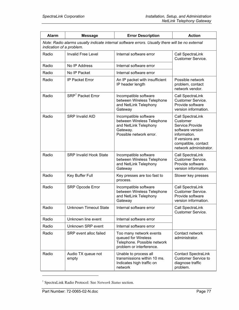
SpectraLink Corporation Installation, Setup, and Administration NetLink Telephony Gateway
Part Number: 72-0065-02-N.doc Page 77
Alarm Message Error Description Action
Note: Radio alarms usually indicate internal software errors. Usually there will be no external indication of a problem.
Radio Invalid Free Level Internal software error Call SpectraLink Customer Service.
Radio No IP Address Internal software error
Radio No IP Packet Internal software error
Radio IP Packet Error An IP packet with insufficient IP header length
Possible network problem, contact network vendor.
Radio SRP1 Packet Error Incompatible software between Wireless Telephone and NetLink Telephony Gateway
Call SpectraLink Customer Service. Provide software version information.
Radio SRP Invalid AID Incompatible software between Wireless Telephone and NetLink Telephony Gateway. Possible network error.
Call SpectraLink Customer Service.Provide software version information. If versions are compatible, contact network administrator.
Radio SRP Invalid Hook State Incompatible software between Wireless Telephone and NetLink Telephony Gateway
Call SpectraLink Customer Service. Provide software version information.
Radio Key Buffer Full Key presses are too fast to process.
Slower key presses
Radio SRP Opcode Error Incompatible software between Wireless Telephone and NetLink Telephony Gateway
Call SpectraLink Customer Service. Provide software version information.
Radio Unknown Timeout State Internal software error Call SpectraLink Customer Service.
Radio Unknown line event Internal software error
Radio Unknown SRP event Internal software error
Radio SRP event alloc failed Too many network events queued for Wireless Telephone. Possible network problem or interference.
Contact network administrator.
Radio Audio TX queue not empty
Unable to process all transmissions within 10 ms. Indicates high traffic on network
Contact SpectraLink Customer Service to diagnose traffic problem.
1 SpectraLink Radio Protocol: See Network Status section.
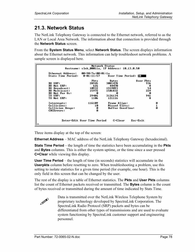
SpectraLink Corporation Installation, Setup, and Administration NetLink Telephony Gateway
Part Number: 72-0065-02-N.doc Page 78
21.3. Network Status The NetLink Telephony Gateway is connected to the Ethernet network, referred to as the LAN or Local Area Network. The information about that connection is provided through the Network Status screen.
From the System Status Menu, select Network Status. The screen displays information about the Ethernet network. This information can help troubleshoot network problems. A sample screen is displayed here.
Three items display at the top of the screen:
Ethernet Address – MAC address of the NetLink Telephony Gateway (hexadecimal).
Stats Time Period – the length of time the statistics have been accumulating in the Pkts and Bytes columns. This is either the system uptime, or the time since a user pressed C=Clear while viewing this display.
User Time Period – the length of time (in seconds) statistics will accumulate in the Userpkts column before resetting to zero. When troubleshooting a problem, use this setting to isolate statistics for a given time period (for example, one hour). This is the only field in this screen that can be changed by the user.
The rest of the display is a table of Ethernet statistics. The Pkts and User Pkts columns list the count of Ethernet packets received or transmitted. The Bytes column is the count of bytes received or transmitted during the amount of time indicated by Stats Time.
Data is transmitted over the NetLink Wireless Telephone System by proprietary technology developed by SpectraLink Corporation. The SpectraLink Radio Protocol (SRP) packets and bytes can be differentiated from other types of transmissions and are used to evaluate system functioning by SpectraLink customer support and engineering personnel.
SpectraLink Corporation Installation, Setup, and Administration NetLink Telephony Gateway
Part Number: 72-0065-02-N.doc Page 79
RX SRP – indicates the number of SRP (SpectraLink Radio Protocol) packets and bytes received. (RX=“received”)
RX Not SRP – number of packets and bytes received addressed to the NetLink Telephony Gateway that are not SRP packets.
RX Broadcast – the number of broadcast packets and bytes received.
RX Multicast – the number of packets and bytes received with the SpectraLink multicast address. (A “multicast” message is sent to more than one destination on the network.)
RX Not For Us – the number of multicast packets and bytes received that were not for the NetLink Telephony Gateway.
TX SRP – the number of SRP packets and bytes transmitted. (TX=“transmitted”)
TX Not SRP – the total number of packets and bytes transmitted that are not SRP packets.
Interrupts – the number of times the Ethernet controller has signaled the microprocessor that it has received or sent a packet.
Collisions – the number of times the Ethernet controller has attempted to send a packet, but another device on the network transmitted at the same time, corrupting the transmission.
Collision Drops – the number of packets the Ethernet controller has discarded because there were over sixteen collisions. After sixteen collisions the Ethernet controller hardware discards the current packet and attempts to send the next packet in its buffer.
CRC Errors – the number of packets discarded by the Ethernet controller because of a CRC (Cyclic Redundancy Check) error.
Frame Align – the number of packets the Ethernet controller discarded because of an error in their frame alignment.
Missed Slots – occurs when the NetLink Telephony Gateway does not have sufficient time to process audio. This number should always be 0 or 1.
Buffer Overflow – Number of times Ethernet controller received more packets than it had buffers to store them. Indicates extreme traffic.
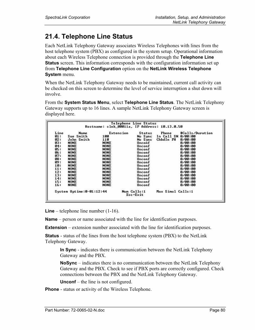
SpectraLink Corporation Installation, Setup, and Administration NetLink Telephony Gateway
Part Number: 72-0065-02-N.doc Page 80
21.4. Telephone Line Status Each NetLink Telephony Gateway associates Wireless Telephones with lines from the host telephone system (PBX) as configured in the system setup. Operational information about each Wireless Telephone connection is provided through the Telephone Line Status screen. This information corresponds with the configuration information set up from Telephone Line Configuration option on the NetLink Wireless Telephone System menu.
When the NetLink Telephony Gateway needs to be maintained, current call activity can be checked on this screen to determine the level of service interruption a shut down will involve.
From the System Status Menu, select Telephone Line Status. The NetLink Telephony Gateway supports up to 16 lines. A sample NetLink Telephony Gateway screen is displayed here.
Line – telephone line number (1-16).
Name – person or name associated with the line for identification purposes.
Extension – extension number associated with the line for identification purposes.
Status - status of the lines from the host telephone system (PBX) to the NetLink Telephony Gateway.
In Sync - indicates there is communication between the NetLink Telephony Gateway and the PBX. NoSync – indicates there is no communication between the NetLink Telephony Gateway and the PBX. Check to see if PBX ports are correctly configured. Check connections between the PBX and the NetLink Telephony Gateway. Unconf – the line is not configured.
Phone - status or activity of the Wireless Telephone.
SpectraLink Corporation Installation, Setup, and Administration NetLink Telephony Gateway
Part Number: 72-0065-02-N.doc Page 81
NoChkIn - the Wireless Telephone has not checked in with an AP. It is out of range or powered off. ChkIn - the Wireless Telephone has checked in and is in communication with an AP. In Call – the Wireless Telephone is in use.
# Calls / Duration – the total number of calls made on this line since the system was brought up, and the total duration of the calls.
System Uptime – length of time the NetLink Telephony Gateway has been powered on.
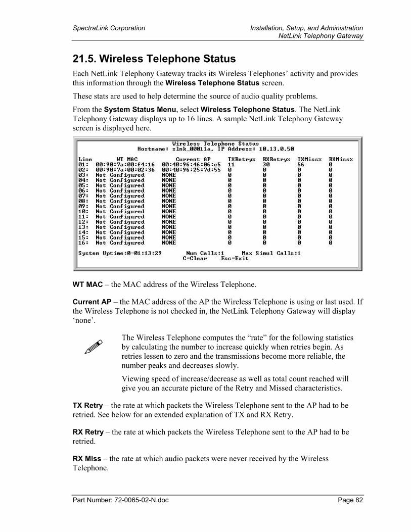
SpectraLink Corporation Installation, Setup, and Administration NetLink Telephony Gateway
Part Number: 72-0065-02-N.doc Page 82
21.5. Wireless Telephone Status Each NetLink Telephony Gateway tracks its Wireless Telephones’ activity and provides this information through the Wireless Telephone Status screen.
These stats are used to help determine the source of audio quality problems.
From the System Status Menu, select Wireless Telephone Status. The NetLink Telephony Gateway displays up to 16 lines. A sample NetLink Telephony Gateway screen is displayed here.
WT MAC – the MAC address of the Wireless Telephone.
Current AP – the MAC address of the AP the Wireless Telephone is using or last used. If the Wireless Telephone is not checked in, the NetLink Telephony Gateway will display ‘none’.
The Wireless Telephone computes the “rate” for the following statistics by calculating the number to increase quickly when retries begin. As retries lessen to zero and the transmissions become more reliable, the number peaks and decreases slowly.
Viewing speed of increase/decrease as well as total count reached will give you an accurate picture of the Retry and Missed characteristics.
TX Retry – the rate at which packets the Wireless Telephone sent to the AP had to be retried. See below for an extended explanation of TX and RX Retry.
RX Retry – the rate at which packets the Wireless Telephone sent to the AP had to be retried.
RX Miss – the rate at which audio packets were never received by the Wireless Telephone.
SpectraLink Corporation Installation, Setup, and Administration NetLink Telephony Gateway
Part Number: 72-0065-02-N.doc Page 83
TX Miss – the rate at which audio packets were successfully transmitted by the Wireless Telephone. There is usually a burst of missed packets at the start of a call; the number should quickly drop to less than 100.
The three statistics across the bottom of the screen give the following information:
System Uptime – the time since the NetLink Telephony Gateway was power cycled or reset. Num Calls – the number of currently active calls on the NetLink Telephony Gateway. Max Simul Calls – the maximum number of simultaneous active calls on the NetLink Telephony Gateway.
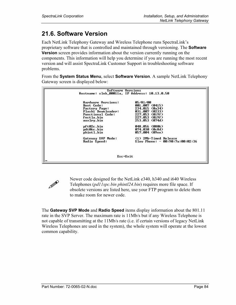
SpectraLink Corporation Installation, Setup, and Administration NetLink Telephony Gateway
Part Number: 72-0065-02-N.doc Page 84
21.6. Software Version Each NetLink Telephony Gateway and Wireless Telephone runs SpectraLink’s proprietary software that is controlled and maintained through versioning. The Software Version screen provides information about the version currently running on the components. This information will help you determine if you are running the most recent version and will assist SpectraLink Customer Support in troubleshooting software problems.
From the System Status Menu, select Software Version. A sample NetLink Telephony Gateway screen is displayed below:
Newer code designed for the NetLink e340, h340 and i640 Wireless Telephones (pd11spc.bin phintl24.bin) requires more file space. If obsolete versions are listed here, use your FTP program to delete them to make room for newer code.
The Gateway SVP Mode and Radio Speed items display information about the 801.11 rate in the SVP Server. The maximum rate is 11Mb/s but if any Wireless Telephone is not capable of transmitting at the 11Mb/s rate (i.e. if certain versions of legacy NetLink Wireless Telephones are used in the system), the whole system will operate at the lowest common capability.
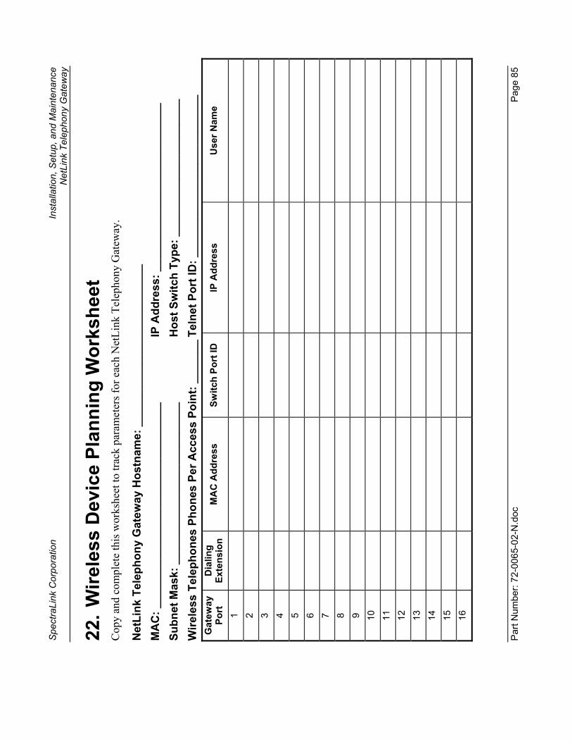
Spec
traLi
nk C
orpo
ratio
n In
stal
latio
n, S
etup
, and
Mai
nten
ance
Net
Link
Tel
epho
ny G
atew
ay
Part
Num
ber:
72-0
065-
02-N
.doc
Pa
ge 8
5
22. W
irele
ss D
evic
e Pl
anni
ng W
orks
heet
C
opy
and
com
plet
e th
is w
orks
heet
to tr
ack
para
met
ers f
or e
ach
Net
Link
Tel
epho
ny G
atew
ay.
Net
Link
Tel
epho
ny G
atew
ay H
ostn
ame:
___
____
____
____
____
____
___
MA
C: _
____
____
____
____
____
____
____
____
IP A
ddre
ss: _
____
____
____
____
____
____
__
Subn
et M
ask:
___
____
____
____
____
____
___
H
ost S
witc
h Ty
pe: _
____
____
____
____
____
_ W
irele
ss T
elep
hone
s Ph
ones
Per
Acc
ess
Poin
t: __
____
_ Te
lnet
Por
t ID
: ___
____
____
____
____
____
___
Gat
eway
Po
rt
Dia
ling
Exte
nsio
n M
AC
Add
ress
Sw
itch
Port
ID
IP A
ddre
ss
Use
r Nam
e
1
2
3
4
5
6
7
8
9
10
11
12
13
14
15
16
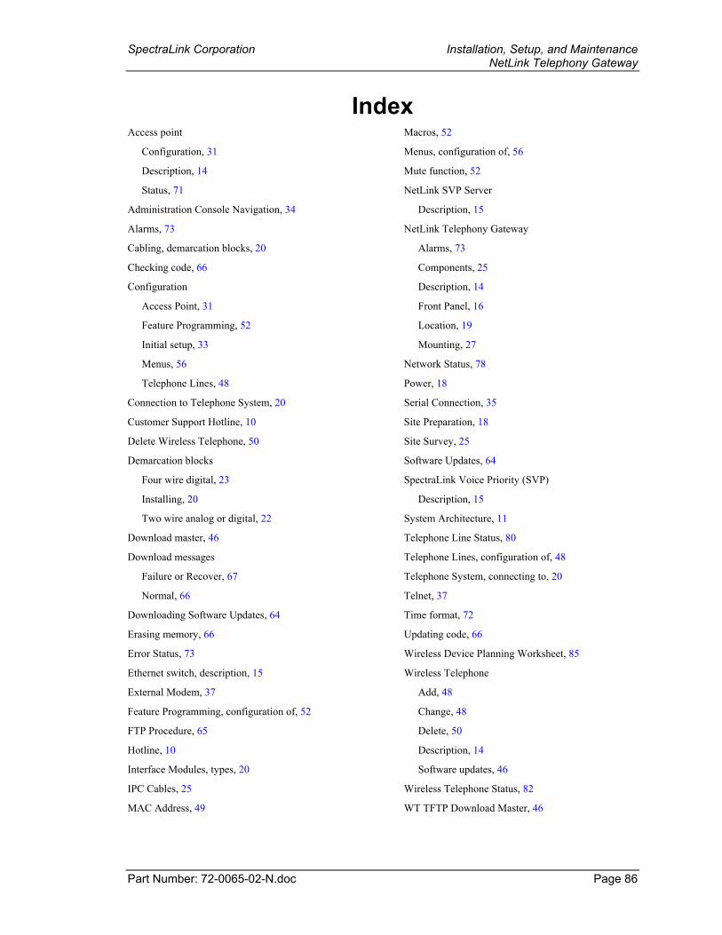
SpectraLink Corporation Installation, Setup, and Maintenance NetLink Telephony Gateway
Part Number: 72-0065-02-N.doc Page 86
Index Access point
Configuration, 31
Description, 14
Status, 71
Administration Console Navigation, 34
Alarms, 73
Cabling, demarcation blocks, 20
Checking code, 66
Configuration
Access Point, 31
Feature Programming, 52
Initial setup, 33
Menus, 56
Telephone Lines, 48
Connection to Telephone System, 20
Customer Support Hotline, 10
Delete Wireless Telephone, 50
Demarcation blocks
Four wire digital, 23
Installing, 20
Two wire analog or digital, 22
Download master, 46
Download messages
Failure or Recover, 67
Normal, 66
Downloading Software Updates, 64
Erasing memory, 66
Error Status, 73
Ethernet switch, description, 15
External Modem, 37
Feature Programming, configuration of, 52
FTP Procedure, 65
Hotline, 10
Interface Modules, types, 20
IPC Cables, 25
MAC Address, 49
Macros, 52
Menus, configuration of, 56
Mute function, 52
NetLink SVP Server
Description, 15
NetLink Telephony Gateway
Alarms, 73
Components, 25
Description, 14
Front Panel, 16
Location, 19
Mounting, 27
Network Status, 78
Power, 18
Serial Connection, 35
Site Preparation, 18
Site Survey, 25
Software Updates, 64
SpectraLink Voice Priority (SVP)
Description, 15
System Architecture, 11
Telephone Line Status, 80
Telephone Lines, configuration of, 48
Telephone System, connecting to, 20
Telnet, 37
Time format, 72
Updating code, 66
Wireless Device Planning Worksheet, 85
Wireless Telephone
Add, 48
Change, 48
Delete, 50
Description, 14
Software updates, 46
Wireless Telephone Status, 82
WT TFTP Download Master, 46