Embed Size (px)
Citation preview
Standard Operating Procedure (SOP) for the Verification and
Re-Verification of EPA’s Ozone Standard Reference
Photometers Office of Air Quality Planning and Standards (OAQPS) Office of Research and Development (ORD) National Risk Management and Research Laboratories
(NRMRL)
SRP/SOP-1 Revision 1
Effective Date Sept, 18 2015
INTERNAL OAQPS PROCEDURE

Document: SRP/SOP-1 Revision 1
Date: 09/18/ 2015
ii Printed copies of this document are uncontrolled. All users are responsible for confirming version status against the electronic version in the document control system.
This page intentionally left blank
Document: SRP/SOP-1 Revision 1
Date: 09/18/ 2015
iv Printed copies of this document are uncontrolled. All users are responsible for confirming version status against the electronic version in the document control system.
Table of Contents
Title Page Revision Date 1. Scope and Applicability…..………….……………………… 1 9/18/2015 2. Summary of Method………………….…..……….………… 6 9/18/2015 3. Definitions and Acronyms…….…………….…….….…….. 12 9/18/2015 4. Health and Safety Warnings…….………….….….……….. 14 9/18/2015 5. Cautions………………………………….…….…….…….... 14 9/18/2015 6. Interferences…………………………………..……..……… 14 9/18/2015 7. Personnel Qualifications/Responsibilities…………...…….. 15 9/18/2015 8. Equipment and Supplies……………………………..……… 15 9/18/2015 9. Procedure………………………………………..….……….. 16 9/18/2015 10. Data and Records Management………..…………....……. 57 9/18/2015 11. Quality Control and Quality Assurance Section….…......... 58 9/18/2015 12 References…………………………………………...…........ 59 9/18/2015
Document: SRP/SOP-1
Revision 1 Date: 09/18/ 2015
Page 1 of 61
Printed copies of this document are uncontrolled. All users are responsible for confirming version status against the electronic version in the document control system.
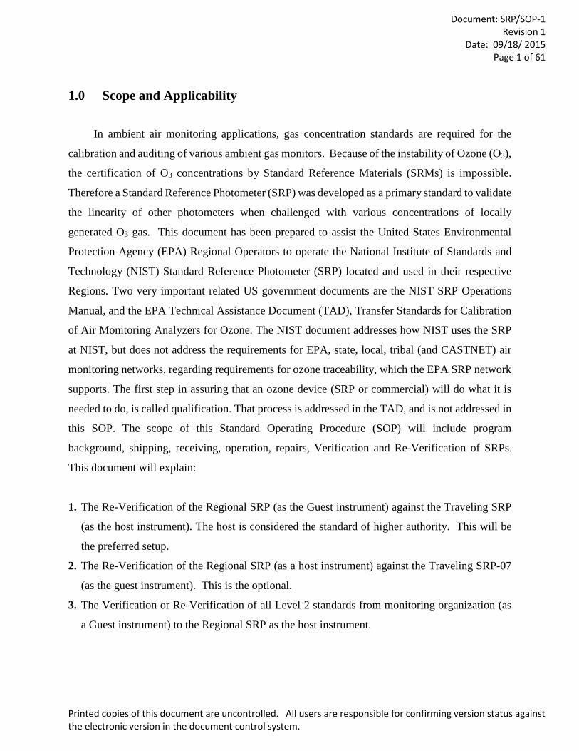
1.0 Scope and Applicability
In ambient air monitoring applications, gas concentration standards are required for the
calibration and auditing of various ambient gas monitors. Because of the instability of Ozone (O3),
the certification of O3 concentrations by Standard Reference Materials (SRMs) is impossible.
Therefore a Standard Reference Photometer (SRP) was developed as a primary standard to validate
the linearity of other photometers when challenged with various concentrations of locally
generated O3 gas. This document has been prepared to assist the United States Environmental
Protection Agency (EPA) Regional Operators to operate the National Institute of Standards and
Technology (NIST) Standard Reference Photometer (SRP) located and used in their respective
Regions. Two very important related US government documents are the NIST SRP Operations
Manual, and the EPA Technical Assistance Document (TAD), Transfer Standards for Calibration
of Air Monitoring Analyzers for Ozone. The NIST document addresses how NIST uses the SRP
at NIST, but does not address the requirements for EPA, state, local, tribal (and CASTNET) air
monitoring networks, regarding requirements for ozone traceability, which the EPA SRP network
supports. The first step in assuring that an ozone device (SRP or commercial) will do what it is
needed to do, is called qualification. That process is addressed in the TAD, and is not addressed in
this SOP. The scope of this Standard Operating Procedure (SOP) will include program
background, shipping, receiving, operation, repairs, Verification and Re-Verification of SRPs.
This document will explain:
1. The Re-Verification of the Regional SRP (as the Guest instrument) against the Traveling SRP
(as the host instrument). The host is considered the standard of higher authority. This will be
the preferred setup.
2. The Re-Verification of the Regional SRP (as a host instrument) against the Traveling SRP-07
(as the guest instrument). This is the optional.
3. The Verification or Re-Verification of all Level 2 standards from monitoring organization (as
a Guest instrument) to the Regional SRP as the host instrument.
Document: SRP/SOP-1
Revision 1 Date: 09/18/ 2015
Page 2 of 61
Printed copies of this document are uncontrolled. All users are responsible for confirming version status against the electronic version in the document control system.
Important Note: If you have any technical questions about the procedure covered
in this US EPA SOP, contact the EPA Technical Lead, Scott Moore at 919-541-
5104, or email [email protected]. For other EPA SRP program questions,
contact Mark Shanis, at 919-541-1323, or email [email protected].
1.2 O3 Photometer Traceability
O3 photometers (used as a standard) can be classified into two basic groups: stationary and
traveling standards. A stationary O3 standard is a photometer (with an internal or external O3
generator) that would be dedicated exclusively to use as a calibration standard. The stationary O3
standard should always be used with clean dry air (preferably zero air) and never used for ambient
air sampling. Consideration should be given to locating the calibration photometer in a clean
laboratory where the photometer can be stationary, protected from physical shock, operated by a
responsible analyst and used as a common standard for all field calibrations via transfer standards.
See Title 40 of the Code of Federal Regulations, Part 50, Appendix D (40 CFR Part 50) Section
5.1. The calibration procedure is based on the photometric assay of O3 concentrations (six
concentration points as per Section 5.5.5) in a dynamic flow system. The concentration of O3 in
an absorption cell is determined from a measurement of the amount of 254 nm light absorbed by
the sample. An O3 traveling standard is a transportable device capable of producing O3
concentrations and accurately analyzing those O3 concentrations that has been verified by another
O3 photometer of a higher or equal level of authority. In ambient air monitoring applications,
precise O3 photometers called transfer standards are required for the calibration of O3 analyzers.
Therefore, an O3 standard must be used to measure ozone that has to be generated and its
concentration measured by the standard and the station analyzer. That is, the concentrations
measured by the analyzer have to be verified, or calibrated, on site. When the monitor to be
calibrated is located at a remote monitoring site, it is necessary to use a transfer standard that is
traceable to a more authoritative standard. “Traceability can be defined as an unbroken record of
documentation ("documentation traceability") or an unbroken chain of measurements and
associated uncertainties ("metrological traceability"). As used here, the word "traceability" always
means "metrological traceability."
Document: SRP/SOP-1
Revision 1 Date: 09/18/ 2015
Page 3 of 61
Printed copies of this document are uncontrolled. All users are responsible for confirming version status against the electronic version in the document control system.
The National Institute of Standards and Technology (NIST) maintains the U.S. national
standards for ozone. In other countries, similar national standards laboratories perform the same
function.
To establish and maintain traceability, the readings of an ozone analyzer are compared to
a NIST made Ozone Standard Reference Photometer (SRP).
This process of using NIST traceable standards to verify the concentrations of an analyzer
used to monitor ambient air for ozone is implemented for all the US EPA, state, local, and tribal,
and CASTNET network ozone analyzers used to make comparisons against the ozone National
Ambient Air Quality Standards. The testing process is called verification. Once the accuracy of a
standard is authenticated, that standard can serve as a reference to establish traceability for other
ozone standards or analyzers. This process can be continued, providing an unbroken chain of
measurements from the final ozone analyzer all the way back to the NIST standards. The final
measurement will have traceability to NIST standards if the following conditions are met:
1. An unbroken chain of measurements back to NIST standards is maintained.
2. Each step of the chain has known and documented uncertainties.
3. There is a quality system to ensure that the ozone standards and associated
measurement equipment maintain their measurement uncertainty (accuracy).” Quoted
from: http://www.nist.gov/pml/mercury_traceability.cfm
Document: SRP/SOP-1
Revision 1 Date: 09/18/ 2015
Page 4 of 61
Printed copies of this document are uncontrolled. All users are responsible for confirming version status against the electronic version in the document control system.
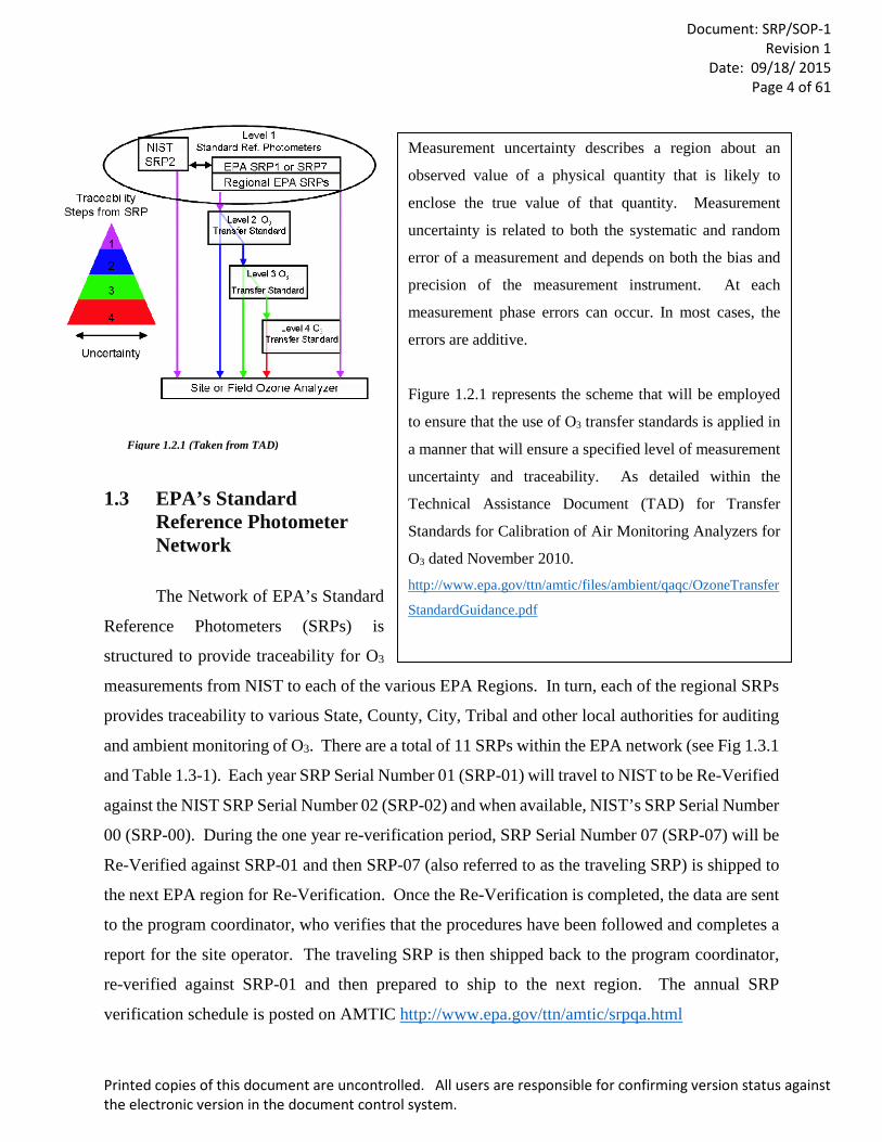
1.3 EPA’s Standard Reference Photometer Network
The Network of EPA’s Standard
Reference Photometers (SRPs) is
structured to provide traceability for O3
measurements from NIST to each of the various EPA Regions. In turn, each of the regional SRPs
provides traceability to various State, County, City, Tribal and other local authorities for auditing
and ambient monitoring of O3. There are a total of 11 SRPs within the EPA network (see Fig 1.3.1
and Table 1.3-1). Each year SRP Serial Number 01 (SRP-01) will travel to NIST to be Re-Verified
against the NIST SRP Serial Number 02 (SRP-02) and when available, NIST’s SRP Serial Number
00 (SRP-00). During the one year re-verification period, SRP Serial Number 07 (SRP-07) will be
Re-Verified against SRP-01 and then SRP-07 (also referred to as the traveling SRP) is shipped to
the next EPA region for Re-Verification. Once the Re-Verification is completed, the data are sent
to the program coordinator, who verifies that the procedures have been followed and completes a
report for the site operator. The traveling SRP is then shipped back to the program coordinator,
re-verified against SRP-01 and then prepared to ship to the next region. The annual SRP
verification schedule is posted on AMTIC http://www.epa.gov/ttn/amtic/srpqa.html
Measurement uncertainty describes a region about an
observed value of a physical quantity that is likely to
enclose the true value of that quantity. Measurement
uncertainty is related to both the systematic and random
error of a measurement and depends on both the bias and
precision of the measurement instrument. At each
measurement phase errors can occur. In most cases, the
errors are additive.
Figure 1.2.1 represents the scheme that will be employed
to ensure that the use of O3 transfer standards is applied in
a manner that will ensure a specified level of measurement
uncertainty and traceability. As detailed within the
Technical Assistance Document (TAD) for Transfer
Standards for Calibration of Air Monitoring Analyzers for
O3 dated November 2010. http://www.epa.gov/ttn/amtic/files/ambient/qaqc/OzoneTransfer
StandardGuidance.pdf
Figure 1.2.1 (Taken from TAD)

Document: SRP/SOP-1
Revision 1 Date: 09/18/ 2015
Page 5 of 61
Printed copies of this document are uncontrolled. All users are responsible for confirming version status against the electronic version in the document control system.
Some of the regional operators have
selected the option to ship their SRP to the
program coordinator to perform annual
maintenance, repairs (if needed) and re-
verification. This Standard Operation
Procedure (SOP) will be focusing on the
re-verification process for the SRP
program. The following re-verification
steps will be discussed in this SOP:
receiving and unpacking SRP-07 from the
cases, setting up SRP-07 to run the re-
verification, running the Quality
Assurance/Quality Control (QA/QC)
checks, setting the re-verification parameters, running the re-verification, breaking down SRP-07,
packing SRP-07 and shipping SRP-07. All the steps required for setting up and comparing SRP 7
(as the Host) to a Regional SRP (as the Guest) start in Subsection 9.2.1 and continue through
subsection 9.4.2. Following the re-verification process there will be a section on repairs and annual
maintenance.
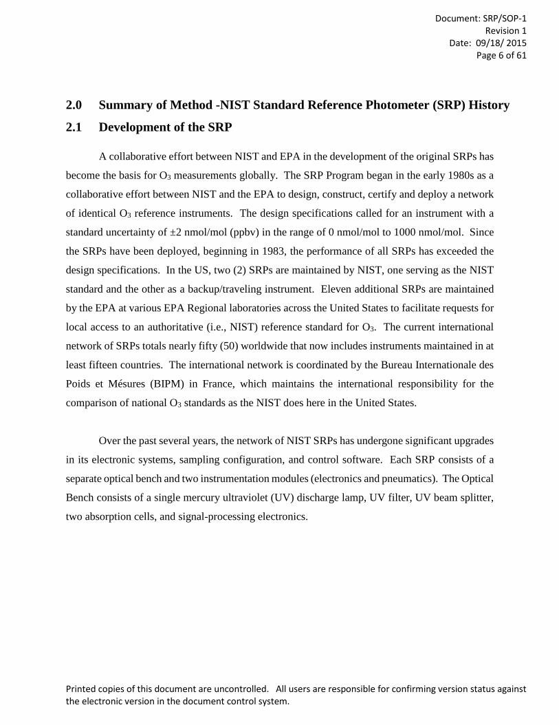
Table 1.3-1 Locations of SRPs
SRP Region Location
SRP-09
SRP-03
SRP-10
SRP-06
SRP-05
SRP-13
SRP-08
SRP-36
SRP-04
SRP-01
SRP-07
Region 1
Region 2
Region 4
Region 5
Region 6
Region 7
Region 8
Region 9
ARB
RTP
RTP
N. Chelmsford, MA
Edison, NJ
Athens, GA
Chicago, IL
Houston, TX
Kansas City, KS
Golden, CO
Richmond, CA
Sacramento, CA
RTP, NC
SRP7 to NIST
Figure 1.3.1 US O3 Program Locations
Document: SRP/SOP-1
Revision 1 Date: 09/18/ 2015
Page 6 of 61
Printed copies of this document are uncontrolled. All users are responsible for confirming version status against the electronic version in the document control system.
2.0 Summary of Method -NIST Standard Reference Photometer (SRP) History
2.1 Development of the SRP
A collaborative effort between NIST and EPA in the development of the original SRPs has
become the basis for O3 measurements globally. The SRP Program began in the early 1980s as a
collaborative effort between NIST and the EPA to design, construct, certify and deploy a network
of identical O3 reference instruments. The design specifications called for an instrument with a
standard uncertainty of ±2 nmol/mol (ppbv) in the range of 0 nmol/mol to 1000 nmol/mol. Since
the SRPs have been deployed, beginning in 1983, the performance of all SRPs has exceeded the
design specifications. In the US, two (2) SRPs are maintained by NIST, one serving as the NIST
standard and the other as a backup/traveling instrument. Eleven additional SRPs are maintained
by the EPA at various EPA Regional laboratories across the United States to facilitate requests for
local access to an authoritative (i.e., NIST) reference standard for O3. The current international
network of SRPs totals nearly fifty (50) worldwide that now includes instruments maintained in at
least fifteen countries. The international network is coordinated by the Bureau Internationale des
Poids et Mésures (BIPM) in France, which maintains the international responsibility for the
comparison of national O3 standards as the NIST does here in the United States.
Over the past several years, the network of NIST SRPs has undergone significant upgrades
in its electronic systems, sampling configuration, and control software. Each SRP consists of a
separate optical bench and two instrumentation modules (electronics and pneumatics). The Optical
Bench consists of a single mercury ultraviolet (UV) discharge lamp, UV filter, UV beam splitter,
two absorption cells, and signal-processing electronics.
Document: SRP/SOP-1
Revision 1 Date: 09/18/ 2015
Page 7 of 61
Printed copies of this document are uncontrolled. All users are responsible for confirming version status against the electronic version in the document control system.
In May 2003, a new electronics module was designed as a plug-compatible replacement
for the original unit to simplify upgrading of existing systems. Several improvements were made
in the overall electronics module design to provide enhanced stability and to simplify operation.
The electronics upgrade also involved a complete redesign of the detector module. The new
detector voltage to frequency (V/f) converters are more stable and three times more sensitive than
the previous converters. This additional stability and sensitivity provides increased measurement
sensitivity through higher resolution scalar counts, a longer source lamp life, a lower noise level
and a smoother output signal. The most recent upgrade to the SRPs solved a previously existing
O3 measurement bias and improved the accuracy of the pressure measurements by using equal
length sample and reference lines, effectively balancing the pressure drop through each sample
pathway. The new dual manifold sampling configuration is now considered standard on the SRP.
New SRPs are produced and delivered using this sampling configuration.
2.2 Hardware Upgrades
SRPs made by NIST and used by EPA have been upgraded over time. From 1989 through
2004, a series of 11 individual upgrades were made, including redesign” of the detector module
(see reference, “Upgrade and Intercomparison…,” June , 2004). The following material in quotes
are derived from the two references listed in section 12.4.
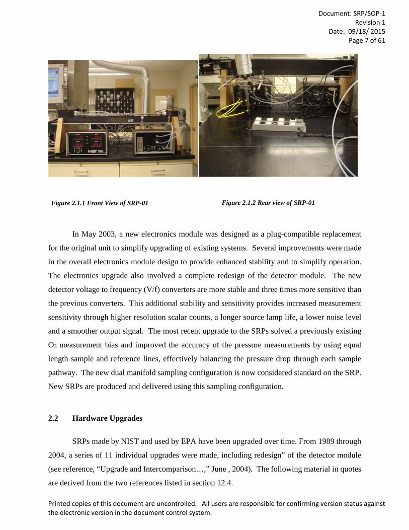
Figure 2.1.1 Front View of SRP-01 Figure 2.1.2 Rear view of SRP-01
Document: SRP/SOP-1
Revision 1 Date: 09/18/ 2015
Page 8 of 61
Printed copies of this document are uncontrolled. All users are responsible for confirming version status against the electronic version in the document control system.
The first upgrade involved “replacing 4 independent function circuit boards, and a separate
relay circuit board, with one main circuit board, called the Digital Interface and Timing Generation
(DI/TG) Board. Board connections and mounting bracket were improved, and a 24 DC volt power
supply added. Critical parameter adjustment controls were installed on the front panel, which
allowed the unit to remain thermally stable during adjustment, which the old design had not
allowed. The main board is a multi-layer board providing more stringent handling of transmitted
signals. Particular attention was paid to separation of the digital and analog grounds to avoid
interference, and various test points are available for convenience during testing. The
specifications of the signal amplifiers used on the temperature and pressure input signals are 50%
more stable than those used in the original design. Electric contact relays used in the original design
for powering the lamp shutter and solenoid valves were replaced by solid state relays, thus
minimizing power spikes throughout the system. The front panel displays for the two scaler
channels, temperature and pressure, are brighter and easier to view”.
“The electronics upgrade also involved a complete redesign of the detector module. The
original housing was costly and impractical. The new design utilizes an extruded aluminum box
with internal mounting brackets. The new detector/ preamp board provides 2 independent, stable
voltages corresponding to the light intensity in the absorption cells and utilizes a signal amplifier
with a factor of 5 improvement in stability compared to its predecessor. The new detector V/f
converters are more stable, and three times faster than the previous ones. These features provide
increased measurement sensitivity through higher resolution scalar counts, and longer source lamp
life. The open-collector devices used in the original design for transmitting the V/f output signals
to the electronics module were replaced with TTL line drivers. Further design improvements were
made such that these signals are now transmitted over independent coaxial cables for improved
signal fidelity. Summary: Overall, the new detector modules provide faster V/f conversion, a lower
noise level, and a smoother output signal.”
“Use of the Industry Standard Architecture (ISA) bus in Personal Computers (PCs) has
vanished, and it has become impossible to purchase a PC with the ISA expansion slots necessary
for the operation of the version 3 software. A fourth generation control program for the SRP has
been developed by NIST. New software was required due to the unavailability of new computers
Document: SRP/SOP-1
Revision 1 Date: 09/18/ 2015
Page 9 of 61
Printed copies of this document are uncontrolled. All users are responsible for confirming version status against the electronic version in the document control system.
with the ISA bus. New computers then became available with the Peripheral Component Interface
(PCI) bus only, which means that the SRPs had to use these PCI control cards. A direct
replacement of the ISA multi-function card previously used was not available in a PCI version.
The PCI replacement uses a different connector, so an additional signal distribution module was
designed and produced to handle the new connector used on the PCI card. This modification
allowed continued use of existing SRP control cables. A direct replacement for the 24-bit Digital
Input/Output (DIO) card for controlling a guest SRP became available for PCI bus operation.
Several of the EPA operators had their SRP computer connected to the Agency network as a
convenient way to store data to a server and work on data from a remote location. Newer
computers may have at least one PCI slot and several e-PCIs.”
A “dual external manifold was designed using borosilicate glass and the same fittings as
on the original SRP nmanifolds.TO incorporate the new manifolds into existing SRPs, the original
manifolds were removed from the front panel of the pneumatics module, and an adaptor plate
installed with 2 Teflon bulkhead unions. The new arrangement has allowed easy connections to
manifolds in commercial ozone instruments.”
By April of 2013, the redesign and testing of the source /optics lamp block with different
mounting components had been made and tested. During the same period, an issue of optical path
length bias had been addressed, and then tested, using a modified design for the optical cell,
incorporating 3°-tilted windows. The SRPs upgraded with these changes have shown improved
overall agreement.
Research is currently in process to adapt the SRP to newer technologies. More information
will become available as solutions are documented.
2.3 Software Upgrades
Since the beginning of the SRP program, control of the instrument was handled in part by
computer. Originally, the SRP was controlled by using a Hewlett Packard HP85B computer with
a General (Control) Program Input/ Output GPIO interface card. This version 1 control software
was written using HP Series 80 software. While certain functions of this operation were
Document: SRP/SOP-1
Revision 1 Date: 09/18/ 2015
Page 10 of 61
Printed copies of this document are uncontrolled. All users are responsible for confirming version status against the electronic version in the document control system.
automated, an operator was required to start each concentration measurement manually and change
O3 generator settings manually. Additionally, an independent computer was required for the
operation of each SRP while verifying one SRP against another SRP. In 1992, NIST developed
an SRP control system based on the personal computer (PC). An Industry Standard Architecture
(ISA) 24-bit digital input/output (DIO) control card was used to interface the SRP to the PC.
Version 2 control software was written using QuickBASIC™ version 4.5. At the request of EPA,
the software was written to emulate the original software. While some improvements were made,
the basic functionality of the SRP control remained the same.
In 1995, NIST developed an automated control system allowing multiple SRPs to be
compared automatically against each other using one PC and without the presence of an operator.
Additionally, analog output signals from commercial O3 instruments could be read simultaneously
by the same PC to provide automated verifications. Version 3 control software was written in the
“C” programming language using a front-end graphical interface similar to Windows™. While
Windows™ version 3.1 was available during this time, the new version 3 control software was
Disk Operating System (DOS)-based. When Windows™ 95 began to be used on SRP control
computers, SRP operators began to notice problems running the version 3 control software in
Windows™ from a DOS shell. Most of the problems were related to reading the analog output
signal from a commercial O3 instrument and seemed to be PC-dependent. Increasing processor
speeds of the newer PCs may have contributed to the problems. For these reasons, in 2000 NIST
began developing a new software/hardware update for the SRP using Peripheral Component
Interconnect (PCI) control cards and Windows-based VisualBasic™ software. Use of the version
4.4.1 SRP control system began at NIST in November 2001 and became available to all other SRP
users in April 2002.
The software called “SRP Control” was written in VisualBasic™ version 6.0 and operates
under the Windows™ NT, 2000 or XP environment. The program works in conjunction with
Excel™ 2003 (version-xls) where all data collected from the program are automatically reported
to templates, which can be customized to suit the user’s needs. The templates can have additional
macros performing specific calculations or operations available in Excel™. The control system is
operated using scripts, which call lower-level functions embedded in the program. The user cannot
modify the lower-level functions, but the default scripts can be modified or new scripts written to
Document: SRP/SOP-1
Revision 1 Date: 09/18/ 2015
Page 11 of 61
Printed copies of this document are uncontrolled. All users are responsible for confirming version status against the electronic version in the document control system.
obtain customized system operations. The ability to customize system operations allows the user
to create custom program control without the possibility of corruption to the basic functions of the
SRP. Comparisons to an SRP can be done for up to three guest instruments (Level 2 transfer
standards), including multiple guest SRPs. The guest system data input can be via SRP digital
interface, serial communication, analog signal or manual input of O3 concentrations from the guest
instrument display. The internal O3 generator available on some guest O3 instrumentation can be
operated using serial communication. Calibration methods created for specific instrumentation
can be saved and recalled for repeated use or linked together in series to provide consecutive
calibrations with different formats on the same instrument. Network access to the control system
providing some control functions is available, but can be difficult to implement with network
security systems. The current version is 4.4.1 from the NIST web site http://www.nist.gov.
NIST has worked on the next upgrade that will enhance some of the graphic display. It
will be possible to connect SRP to SRP via Universal Serial Bus (USB) interface. However,
additional hardware would need to be purchased, and there is a known O3 lamp voltage issue that
limits the control of the O3 lamp from zero-100% to zero-50%. The new software was written in
Lab View, and then compiled into an executable program to run on the computer (Windows 7
operating system). The free driver will need to be downloaded, in order to run the program.
As indicated, Lab View will replace Visual Basic. The version of the software in Lab View
is currently being Beta tested, by NIST, EPA and Canada. It is not yet ready for distribution. When
it becomes available, it will be obtained through the assistance of the EPA ORD SRP coordinator.
For the time being, until the new software is installed, for those operators with Windows XP, since
XP is no longer supported, workarounds may be needed. At least one SRP operator has to use a
USB drive to get the data off the SRP computer.
Proposed Future Upgrades: Low voltage temperature cards, made by the company
STOLAB, to minimize a 0.2 °C observed temperature bias; four temperature sensors, one each on
the inlet and outlet of each of the cells. Possibly two pressure transducers to measure the pressure
from each cell and the LabView Control Software.
Document: SRP/SOP-1
Revision 1 Date: 09/18/ 2015
Page 12 of 61
Printed copies of this document are uncontrolled. All users are responsible for confirming version status against the electronic version in the document control system.
3. Definitions and Acronyms:
3.1. Definitions
Qualification: The process of demonstrating that a candidate device is sufficiently stable (repeatable) to be used as a transfer standard. Repeatability is necessary over a range of variables, such as temperature, line voltage, barometric pressure, elapsed time, operator adjustments, or other conditions that might be encountered during intended use of the device. Tests and possible compensation techniques for common variables may be provided.
Verification: confirmation by examination and provision of objective evidence that specified requirements have been fulfilled.
NOTES:
1. Comparison is made without making any adjustments to make the analyzer performance (concentration) match the concentration of the higher standard that is closer to NIST in comparison traceability. 2. Verification should not be confused with calibration of a measuring system, or vice versa. Verification of the accuracy of a transfer standard is established by (1) relating the output to a O3 standard of higher authority (level) and (2) demonstrating that the repeatability of the transfer standard is within the performance acceptance limits. Calibration involves the possibility of adjustment, verification does not.
Re-verification: While the principle accuracy of a transfer standard is established during verification, the confidence in that accuracy is maintained by continual re-verification to demonstrate stability. The objective is to show, to the greatest extent possible, that the transfer standard did not change significantly between verification and use.(TAD, 2013)
Traceability: is the “property of a measurement result whereby the result can be related to a stated reference through a documented unbroken chain of calibrations, each contributing to the measurement uncertainty” (ISO). (TAD, 2013)
3.2 Acronyms and Abbreviations
AC- Alternating Current
BIPM- Bureau International des Poids et Méasures
CFR - Code of Federal Regulations
CHGMI- Czech Hydro-meteorological Institute, Prague, Czech Republic
DC Direct Current
DIO Digital Input /Output
DOS Disk Operating System
Document: SRP/SOP-1
Revision 1 Date: 09/18/ 2015
Page 13 of 61
Printed copies of this document are uncontrolled. All users are responsible for confirming version status against the electronic version in the document control system.
e-CFR- electronic version of the Code of Federal Regulations
EPA- United States Environmental Protection Agency
Mb- millibar
mV- millivolt(s 1000 mV = 1.0 Volts Direct Current (DC)
MFC- Mass Flow Controller
NIST- National Institute of Standards and Technology
NRMRL- National Risk Management and Research Laboratories
O2- Oxygen
O3 - Ozone
OAQPS- Office of Air Quality Planning and Standards
OD- Outer Diameter
ORD- Office of Research and Development
PC- personal computer
PCI- Peripheral Component Interface
PID Proportional-Integral-Derivative (Controller )
PPM- parts per million
QA/QC- Quality Assurance/Quality Control
RTD- Resistance Temperature Detectors
RTP - Research Triangle Park, NC
SLPM- Standard Liters per minute (?)
SOP- Standard Operation Procedure
SRM- Standard Reference Material
SRP- Standard Reference Photometer
STOLAB- Stow Laboratories, 7 Kane Industrial Drive, Hudson, MA 01749
TAD- Technical Assistance Document
USB- Universal Serial Bus
UV- UltraViolet
VAC- Volts Alternating Current
V/f - Voltage to Frequency (Converter)
Document: SRP/SOP-1
Revision 1 Date: 09/18/ 2015
Page 14 of 61
Printed copies of this document are uncontrolled. All users are responsible for confirming version status against the electronic version in the document control system.
4. Health and Safety Warnings: • Because ozone is regulated because it can cause health effects, the ozone generated in
the pursuit of this procedure must be vented in a way that does not jeopardize anyone’s
health.
• Since the SRP has a large glass cell, care must be taken in handling and, especially when
packing and unpacking the cell for the traveling SRP.
• Since UV light is the basis of detection, and must be generated (by a UV lamp) for the
method to work, care should be taken to protect the user from any negative effects of
UV light.
• There may be, at times, areas of significant voltage in the electronics module, so no
water should be used near that module when it is in use. The power should be turned off
if any repairs are attempted. And any such efforts should proceed with caution, in case
any static charge has built up.
5. Cautions: Since there are important functions carried out by the pneumatic and electronic modules of
the SRP, care should be taken to minimize any over pressure in the system, when reassembling
the traveling SRP for use, and then turning on; and to minimize stress to the circuit board
connections. Be sure to pack the glass cell(s) of the traveling SRP carefully.
6. Interferences: There can be interferences from other molecules of gasses that also absorb UV light in the
wave lengths that ozone absorbs at. This, in particular, includes certain Volatile Organic Carbon
molecules (VOCs), and, to some extent, NO2. However, the SRPs are provided zero air, or zero
air with ozone only and so these other gasses are not a source of error for SRP vs SRP, or SRP
vs commercial ozone analyzer comparisons for which this SOP is used, unless the zero air is not
adequately scrubbed.
Document: SRP/SOP-1
Revision 1 Date: 09/18/ 2015
Page 15 of 61
Printed copies of this document are uncontrolled. All users are responsible for confirming version status against the electronic version in the document control system.
7. Personnel Qualifications:
SRP operation to perform the CFR required verification of State local, tribal, and
CASTNET primary ozone standards will be accomplished by an SRP operator that has been
through the step by step hands-on SRP Training provided by EPA RTP SRP technical lead.
Personnel should have experience calibrating ozone analyzers, including providing of zero air,
and independent generation of ozone.
8. Equipment and Supplies Each of the 8 Regions with an SRP:
SRP: 3 modules (Glass Cell, Cell Stand, Pressure Module, Electronic Module); Glass Manifold,
and connecting cables, and dedicated desktop computer, with latest SRP software; Shipping cases
(1for each module; and one for miscellaneous items).
Zero Air Supply: Either is a commercial unit, or assembled by SRP lab operator, or is a
combination of both. Normally contains a pump, air storage/ballast tank, pressure regulator and
gauge, adsorbent scrubbers, particulate removing filter (as needed). The scrubbers, or equivalent,
must remove constituents that might absorb UV in the wavelength(s) that ozone absorbs; in
particular, some Volatile Organic compounds (VOCs), N2 and O2. Typical scrubber materials
include activated (heat-treated) charcoal, Mole sieve, etc. Scrubbing materials may need to be
replaced, or, in the case of the heat treated (activated) charcoal, the materials may need to
periodically be re-heat-treated. The performance of the zero air supply can be checked periodically,
or if a problem is suspected, by comparing the “zero” air it provides against the output of an ultra
pure air cylinder from a trusted and respected vendor who provides a certificate of analysis that
shows any impurities that independent analyses found were still in the cylinder, and at what
amount.
Power Supply: NIST recommends a power line buffer, so that it provides stable voltage
frequency, so that there are no unwanted effects on the performance of the electronics module.
SRP Support Lab Equipment: NIST traceable Temperature, Pressure, STOLab calibrator and
Voltage sensor used to independently check, and, as needed, recalibrate the pressure and
Document: SRP/SOP-1
Revision 1 Date: 09/18/ 2015
Page 16 of 61
Printed copies of this document are uncontrolled. All users are responsible for confirming version status against the electronic version in the document control system.
temperature sensors that are in each of the NIST-made EPA SRPs; as well as to check the many
different voltages that have to be correct throughout the electrical circuitry of the electronics
module. This equipment needs to be equal to or greater than the acceptance criteria in section 9
and verified against the NIST traceable standards annually.
9.0 Ozone SRP to SRP or Standard Comparison Procedure
9.1 Pre-SRP Comparison Considerations 9.1.1 Qualification
Qualifications are rarely ever run any more. Years ago, new O3 analyzers were put out in the market
with no type of qualification being run on them. These days the manufacturer will run any new instrument
against a Lab Standard that is maintained at the factory, and this may be considered a Qualification.
However, when a request for a Qualification is made, here are some operational parameters that should be
considered:
SRP vs. a Candidate to be used as Level 2 Transfer Standard (TAD Page 2-5 ¶1)
Qualification: Once, new or after major repair (TAD Page 3-2, ¶1, Figure 3-1)
Range: The Qualification should be testing the full range of the instrument. However, this range is not
fully defined. In the TAD (Page 1-4 ¶1), there is a reference in the CFR-50 that refer to the full range of
the instrument. Pass/Fail criteria for a Qualification: Slope 1±.04 and Intercept 0 ppb ±4 ppb; see
TAD Page 1-4 ¶1)
• Instrument Stability Factor: 0.7
• Data Quality Factor: 0.7
• Number of Concentration Points (not including Zero): minimum of 6
• Number of Concentration Points (including Zero at start and end): minimum of 8
• Points per Concentration: Average of at least 7 points.
• Number of Cycles: Minimum of one cycle per day for 6 days under various conditions (see
TAD Appendix B) Temp/Pressure/Line Voltage. It may be noted that running a
Qualification under varius Room Temperatures, Pressures and various Line Voltages may
Document: SRP/SOP-1
Revision 1 Date: 09/18/ 2015
Page 17 of 61
Printed copies of this document are uncontrolled. All users are responsible for confirming version status against the electronic version in the document control system.
be very difficult or even impractical in today’s laboratories. It should also be noted that
after passing the Qualification, the instrument should now have a Verification performed on
it.
9.1.2 Verification The Verification is defined in the TAD 1-6 ¶4, 3-2 ¶2. This definition is often referred to as a 6 by 6.
For any new Level 2 Transfer Standard, this Verification is mandatory.
• Level 2 SRP vs. Qualified Instrument to be used as Level 2 Transfer Standard (TAD Page 2-5 ¶1)
• Verification (6x6): Once after qualification, new or after major repair (TAD Page 3-2, ¶1)
• Range: (90 % ± 5) % of the upper range limit (TAD Section 4.2) RSD of six slopes 3.7 % Std. Dev.
of six intercepts 1.5, TAD Fig. 3-1) and a Slope of 1 ± 3.0 % and an intercept of 0 ± 3 ppb. RSD =
(Standard Deviation of six slopes)/(Average of six slopes)*100
• Setup Parameters:
• Instrument Stability Factor: 0.7
• Data Quality Factor: 0.7
• Number of Concentration Points (not including Zero): 6 minimum
• Number of Concentration Points (including Zero at start and end): 8 minimum
• Points per Concentration: 7 minimum
• Number of Cycles: 6 (1 (minimum) each on 6 different days TAD Section 4.2)
When running a Verification, the automated feature of the SRP Program can be very useful. If a
Verification is started on a Thursday and allowed to run over the weekend, then the Verification could be
completed by Tuesday morning. A couple of tricks could be used to extend the run time of each cycle.
Even though only one per day is required, more can be run. The cycle can be set up to run more than 6
concentration points. If the cycle is increased to 12 or 14 concentration points with 12 points per
concentration, each cycle may take up to three hours. The other trick that can be used to extend the cycle
time is in the calibration file. When a calibration is set up, you are prompted to save it. Save the calibration
(as an example) as A.met, and save it again as B.met and save it again as C.met. Now open B.met and in
the lower right hand corner there is a box that is labeled “Link Method”. Click on the down arrow and find
the C.met and save the method (or calibration ). Now do the same for the A.met, except under “Link
Document: SRP/SOP-1
Revision 1 Date: 09/18/ 2015
Page 18 of 61
Printed copies of this document are uncontrolled. All users are responsible for confirming version status against the electronic version in the document control system.
Method” find and select the B.met. What will happen is that the first calibration (cycle) will run until it has
completed and then the second (B.met) will run until it is completed and then finally the third calibration
will run (C.met) and when it is completed, it will go into “Standby”.
9.1.3. Re-Verification
The Re-Verification is the procedure used most often by all the SRP Operators.
A Re-Verification can be run on a Level 2 Standard as long as there have been no major repairs to the
instrument. Major repairs would include replacement of the cell or cells, a mother board, a pressure
transducer or a temperature probe. Any annual maintenance, cleaning, replacement of a pump or of a lamp
would not be considered a “Major Repair” if the instrument readings return to normal.
The Re-Verification can also be an SRP Level 1 vs. an SRP Level 1. The NIST comparison against an
EPA SRP is essentially Level 1 as there is no higher authority currently available for Ozone Analysis. NIST
will refer to the Re-Verification as a “Report of Calibration”. See NIST Verification 2014.pdf. Our goal is
to run our Re-Verifications of SRP to SRP in as close a pattern as NIST would run. Typically, NIST will
run 40 to 50 cycles over a three- to four-day period. NIST will run concentrations from zero to 1000 ppb
and may include a set of zero to 500 ppb. BIPM typically will run zero to 500 ppb. Running comparisons
from zero to 500 ppb, as NIST and BIPM do, will aid us in being comparable to the worldwide network of
SRPs.
The following is a list of the recommended parameters that a Re-Verification should be set for the Guest
Level 2 Standard along with the location of the reference in the TAD.
http://www.epa.gov/ttn/amtic/files/ambient/qaqc/OzoneTransferStandardGuidance.pdf
SRP vs. Level 2 Transfer/Lab Standard
• Re-Verification: Annual (TAD Page 1-4, Paragraph 1)
• Range: Full Range of Instrument (Slope 1 ±. 03 and Intercept 0 ppb ± 3 ppb; see TAD Page 1-4 ¶1)
• Instrument Stability Factor: 0.7
• Data Quality Factor: 0.7
Document: SRP/SOP-1
Revision 1 Date: 09/18/ 2015
Page 19 of 61
Printed copies of this document are uncontrolled. All users are responsible for confirming version status against the electronic version in the document control system.
• Number of Concentration Points (not including Zero): 6
• Number of Concentration Points (including Zero at start and end): 8
• Points per Concentration: 7
• Number of Cycles: 3 (all can be completed on the same day)
All instruments should be started at an Instrument Stability Factor and a Data Quality Factor of 0.7 each.
If it is necessary to bump up these factors due to instability in the Guest Standard, the factors can be
increased, but a note of why this increase was needed must be entered into the “Comment” section of the
calibration file. NOTE: If the SRP cannot achieve these factors of 0.7, the SRP then is in need of repair and
should not be used until corrected.
A summary report if the level 2 verification will be provided to the monitoring organizations.
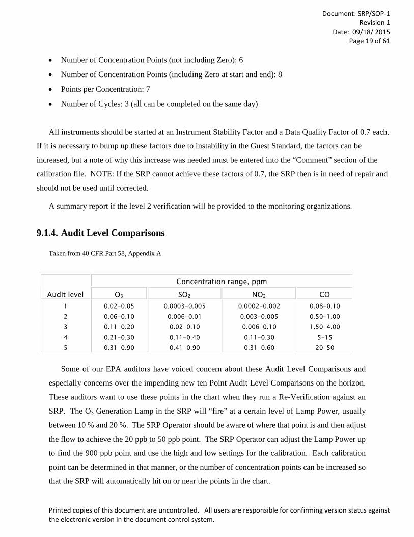
9.1.4. Audit Level Comparisons
Taken from 40 CFR Part 58, Appendix A
Audit level
Concentration range, ppm
O3 SO2 NO2 CO 1 0.02-0.05 0.0003-0.005 0.0002-0.002 0.08-0.10 2 0.06-0.10 0.006-0.01 0.003-0.005 0.50-1.00 3 0.11-0.20 0.02-0.10 0.006-0.10 1.50-4.00 4 0.21-0.30 0.11-0.40 0.11-0.30 5-15 5 0.31-0.90 0.41-0.90 0.31-0.60 20-50
Some of our EPA auditors have voiced concern about these Audit Level Comparisons and
especially concerns over the impending new ten Point Audit Level Comparisons on the horizon.
These auditors want to use these points in the chart when they run a Re-Verification against an
SRP. The O3 Generation Lamp in the SRP will “fire” at a certain level of Lamp Power, usually
between 10 % and 20 %. The SRP Operator should be aware of where that point is and then adjust
the flow to achieve the 20 ppb to 50 ppb point. The SRP Operator can adjust the Lamp Power up
to find the 900 ppb point and use the high and low settings for the calibration. Each calibration
point can be determined in that manner, or the number of concentration points can be increased so
that the SRP will automatically hit on or near the points in the chart.
Document: SRP/SOP-1
Revision 1 Date: 09/18/ 2015
Page 20 of 61
Printed copies of this document are uncontrolled. All users are responsible for confirming version status against the electronic version in the document control system.
9.1.5 Calibrations for Scientific Research
On very rare occasions, the SRP Operator may receive requests to perform an O3 calibration
for scientific research. It is entirely up to the operator to decide to perform this calibration. The
SRP Operator should never allow a commercial instrument to feed O3 to the SRP to avoid any type
of cross contamination. Any of the Pass/Fail criteria would be based upon the QA Project Plan
provided to the SRP Operator.
An organization may request that the SRP operator calibrate their commercial analyzer. If a
research organization here at RTP requests the calibration of a commercial analyzer, the RTP SRP
operator may do the calibration. If asked for a recommendation, a copy of this SOP may be
provided.
9.1.6 Zero – Span Check
Calibration for scientific research is actually a subject that needs to be approached very
carefully. It is not the intent of this program to fix or “tweak” Guest instruments to work better.
The intent is a verification and that is all. Again, it is entirely up the SRP operator to run a Zero
and Span. If an Operator should decide to do this, it would be best if the owner of the Guest
instrument be present and let the owner do the adjustment to their own instrument. If the owner
wants you to make the adjustment and you are willing to do so, you should get their permission in
writing first. In either case, you should record what the Slope and Intercept were before and after
the Zero-Span Check.
Additionally, sometimes a Guest Instrument will arrive at the Region, and it is not working.
The SRP Operator is not responsible for any repairs to any of these instruments. However, some
of the SRP Operators are very sensitive to the time and travel that may be involved in getting a
Guest to the Region. Again, it is entirely up the SRP Operator to decide if the repair can be done
easily and quickly in house. If the SRP Operator is willing to do the repair, you should get the
permission of the owner in writing first. Extreme caution should also be used in making repairs:
the more the Operator does, the more individuals will come to rely on the Operator doing these
things. The Guest owner should be reminded that, before they bring in the Guest, it would be a

Document: SRP/SOP-1
Revision 1 Date: 09/18/ 2015
Page 21 of 61
Printed copies of this document are uncontrolled. All users are responsible for confirming version status against the electronic version in the document control system.
good time to do the annual maintenance on it. They should also run the Guest and make sure it is
fully operational before it leaves their laboratory.
9.1.7 Running Multiple Guests at One Time
Each of the Regional SRPs has the capability of running up to three different Guests at a
time. Most of the computers have only two serial ports to communicate to three serial devices. A
USB to Serial adapter can be purchased and installed on the computer, and this adapter works very
well. Analog input may be an option that will not be supported in the future, but an analog-to-
digital volt meter can be purchased, and a driver has been written for the SRP to communicate
with it. For further details, please contact your program coordinator.
9.2 Procedure: SRP-07 INITIAL SETUP
Note: All the steps required for setting up and comparing SRP 7 (as the Host) to a Regional SRP (as the Guest) start in Subsection 9.2.1 and continue through subsection 9.4.2.
9.2.1 Receiving and Inspection
When the SRP-07 arrives from EPA in Research Triangle Park (RTP) the following items
will in the shipping containers:
Contents:
• Optical Bench • Pneumatics Module • Electronics Module • DB37 pin male to female cable • Detector Cable and Scalar 1 and 2 cables. • J1 Cable • Power Cable • Sample Teflon line • Reference Teflon line
Inspect each of the shipping containers carefully for any obvious damage during shipping.
If there is significant damage to any of the cases, please take a picture of the damage and contact
the program coordinator as soon as possible. Four different types of cases are now being used.
Some of the Regions received a set of two Silver A&J cases. These cases are old but some of them
Document: SRP/SOP-1
Revision 1 Date: 09/18/ 2015
Page 22 of 61
Printed copies of this document are uncontrolled. All users are responsible for confirming version status against the electronic version in the document control system.
are still in use. There is a set of Blue A&J cases that hold the Optical Bench, Pneumatics Module
and the Electronics Modules separately. For shipping a Regional SRP to the Program Coordinator
for Re-Verification or repairs, either of these cases would be preferred. SRP-07 will usually be
shipped in a set of three Starlite cases that were purchased and cut specifically for SRP-07. A
newer set of cases has been purchased that consist of one Starlite case for the Optical Bench and
two Pelican cases for the two modules. The program is not endorsing any one case over the other
but just documenting what is being used for shipping the SRPs around the country.
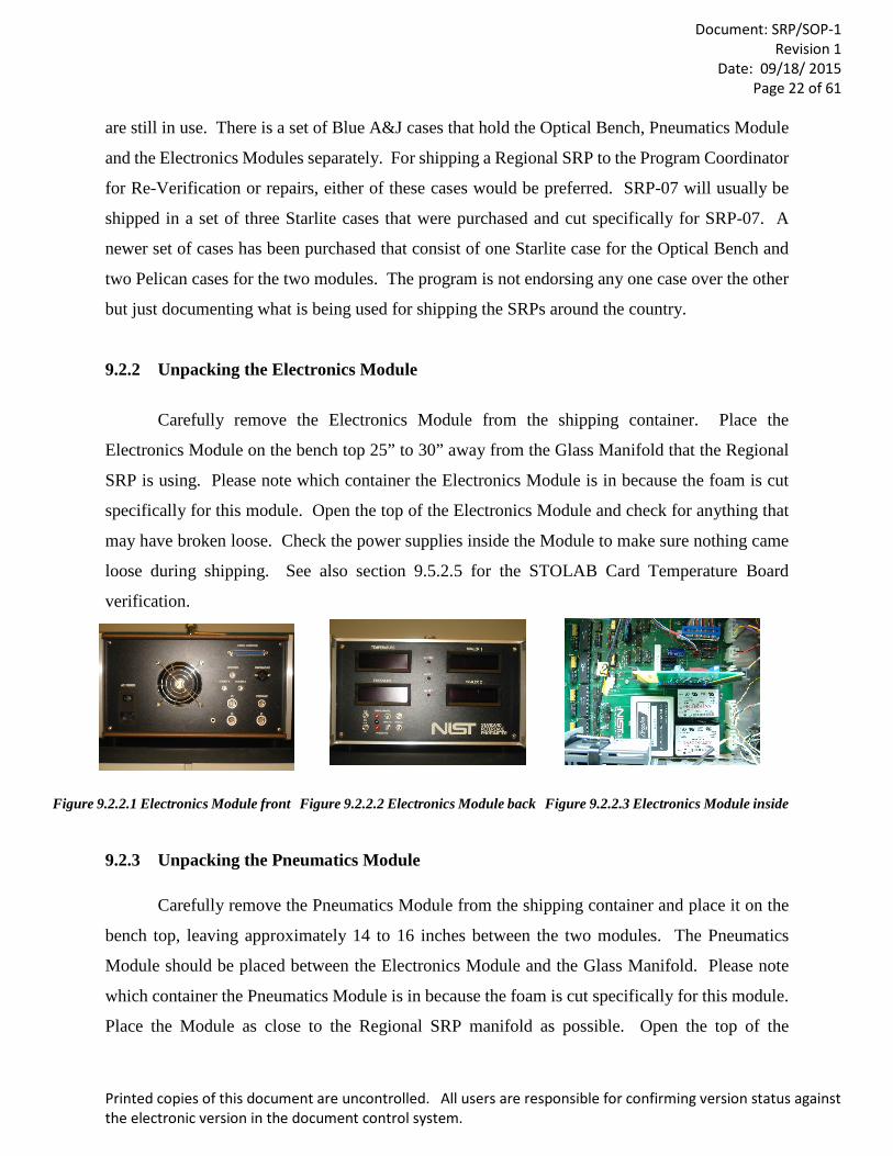
9.2.2 Unpacking the Electronics Module
Carefully remove the Electronics Module from the shipping container. Place the
Electronics Module on the bench top 25” to 30” away from the Glass Manifold that the Regional
SRP is using. Please note which container the Electronics Module is in because the foam is cut
specifically for this module. Open the top of the Electronics Module and check for anything that
may have broken loose. Check the power supplies inside the Module to make sure nothing came
loose during shipping. See also section 9.5.2.5 for the STOLAB Card Temperature Board
verification.
Figure 9.2.2.1 Electronics Module front Figure 9.2.2.2 Electronics Module back Figure 9.2.2.3 Electronics Module inside
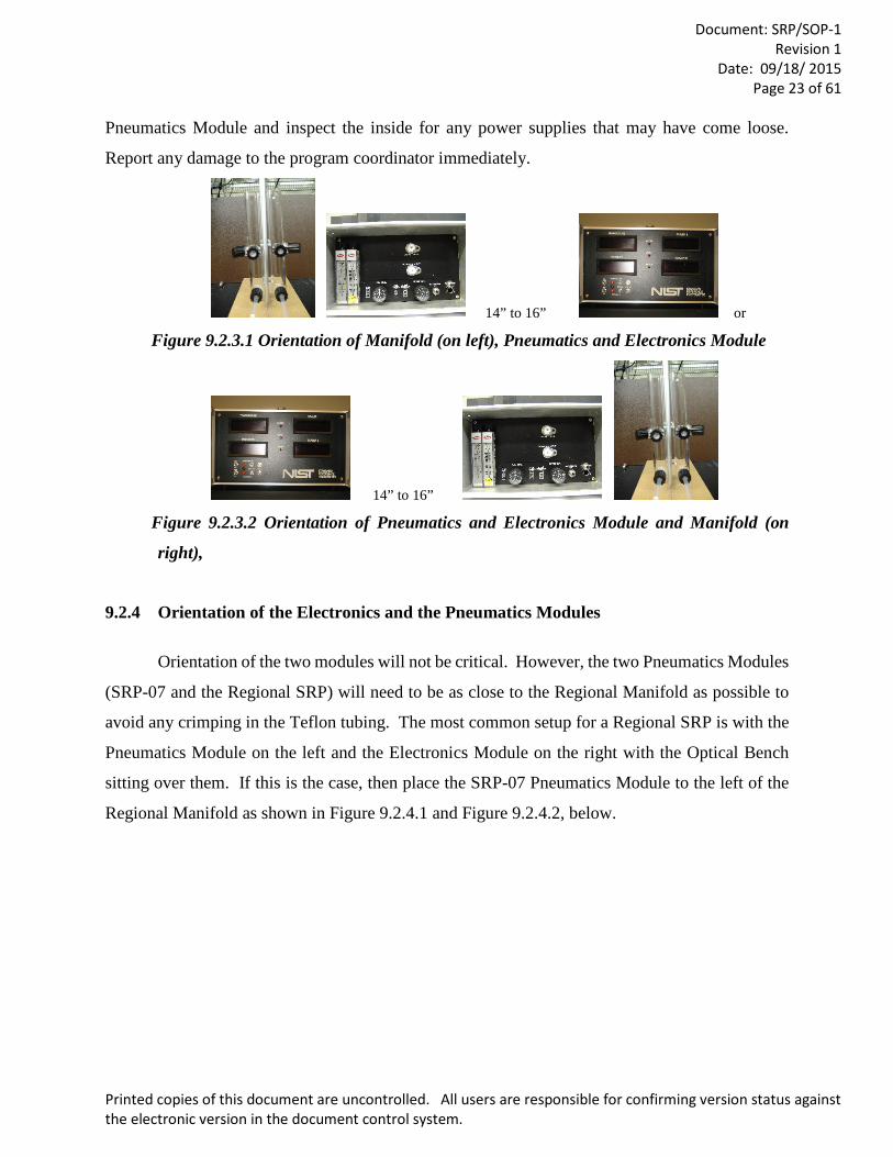
9.2.3 Unpacking the Pneumatics Module
Carefully remove the Pneumatics Module from the shipping container and place it on the
bench top, leaving approximately 14 to 16 inches between the two modules. The Pneumatics
Module should be placed between the Electronics Module and the Glass Manifold. Please note
which container the Pneumatics Module is in because the foam is cut specifically for this module.
Place the Module as close to the Regional SRP manifold as possible. Open the top of the
Document: SRP/SOP-1
Revision 1 Date: 09/18/ 2015
Page 23 of 61
Printed copies of this document are uncontrolled. All users are responsible for confirming version status against the electronic version in the document control system.
Pneumatics Module and inspect the inside for any power supplies that may have come loose.
Report any damage to the program coordinator immediately.
14” to 16” or
Figure 9.2.3.1 Orientation of Manifold (on left), Pneumatics and Electronics Module
14” to 16”
Figure 9.2.3.2 Orientation of Pneumatics and Electronics Module and Manifold (on
right),
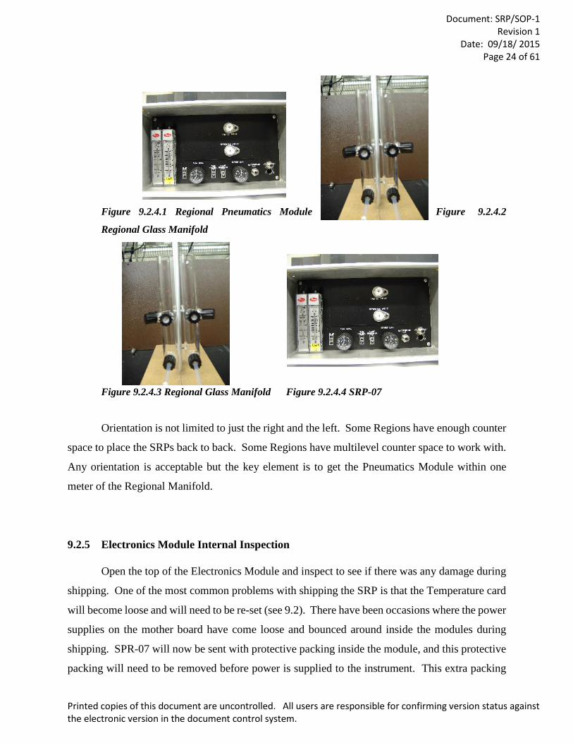
9.2.4 Orientation of the Electronics and the Pneumatics Modules
Orientation of the two modules will not be critical. However, the two Pneumatics Modules
(SRP-07 and the Regional SRP) will need to be as close to the Regional Manifold as possible to
avoid any crimping in the Teflon tubing. The most common setup for a Regional SRP is with the
Pneumatics Module on the left and the Electronics Module on the right with the Optical Bench
sitting over them. If this is the case, then place the SRP-07 Pneumatics Module to the left of the
Regional Manifold as shown in Figure 9.2.4.1 and Figure 9.2.4.2, below.
Document: SRP/SOP-1
Revision 1 Date: 09/18/ 2015
Page 24 of 61
Printed copies of this document are uncontrolled. All users are responsible for confirming version status against the electronic version in the document control system.
Figure 9.2.4.1 Regional Pneumatics Module Figure 9.2.4.2
Regional Glass Manifold
Figure 9.2.4.3 Regional Glass Manifold Figure 9.2.4.4 SRP-07
Orientation is not limited to just the right and the left. Some Regions have enough counter
space to place the SRPs back to back. Some Regions have multilevel counter space to work with.
Any orientation is acceptable but the key element is to get the Pneumatics Module within one
meter of the Regional Manifold.
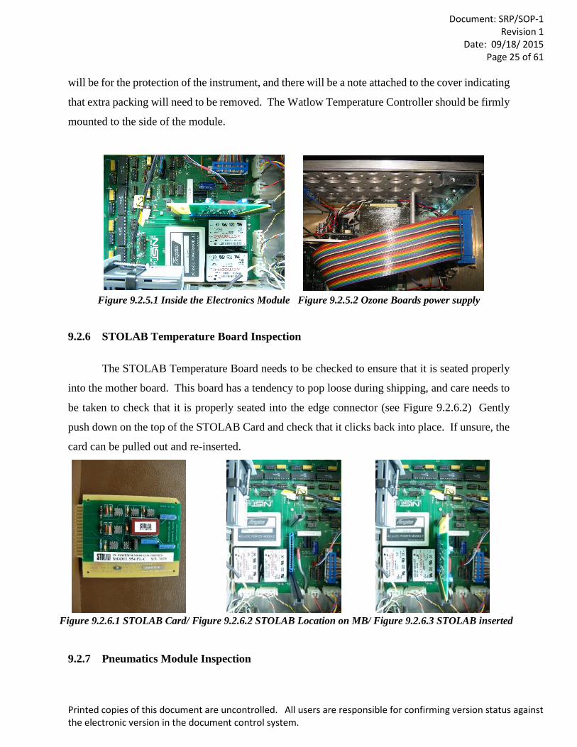
9.2.5 Electronics Module Internal Inspection
Open the top of the Electronics Module and inspect to see if there was any damage during
shipping. One of the most common problems with shipping the SRP is that the Temperature card
will become loose and will need to be re-set (see 9.2). There have been occasions where the power
supplies on the mother board have come loose and bounced around inside the modules during
shipping. SPR-07 will now be sent with protective packing inside the module, and this protective
packing will need to be removed before power is supplied to the instrument. This extra packing
Document: SRP/SOP-1
Revision 1 Date: 09/18/ 2015
Page 25 of 61
Printed copies of this document are uncontrolled. All users are responsible for confirming version status against the electronic version in the document control system.
will be for the protection of the instrument, and there will be a note attached to the cover indicating
that extra packing will need to be removed. The Watlow Temperature Controller should be firmly
mounted to the side of the module.
Figure 9.2.5.1 Inside the Electronics Module Figure 9.2.5.2 Ozone Boards power supply
9.2.6 STOLAB Temperature Board Inspection
The STOLAB Temperature Board needs to be checked to ensure that it is seated properly
into the mother board. This board has a tendency to pop loose during shipping, and care needs to
be taken to check that it is properly seated into the edge connector (see Figure 9.2.6.2) Gently
push down on the top of the STOLAB Card and check that it clicks back into place. If unsure, the
card can be pulled out and re-inserted.
Figure 9.2.6.1 STOLAB Card/ Figure 9.2.6.2 STOLAB Location on MB/ Figure 9.2.6.3 STOLAB inserted
9.2.7 Pneumatics Module Inspection
Document: SRP/SOP-1
Revision 1 Date: 09/18/ 2015
Page 26 of 61
Printed copies of this document are uncontrolled. All users are responsible for confirming version status against the electronic version in the document control system.
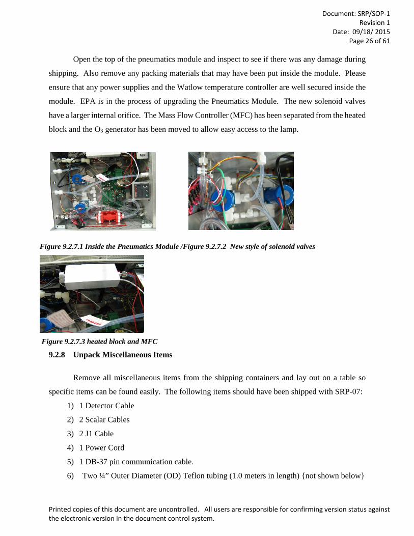
Open the top of the pneumatics module and inspect to see if there was any damage during
shipping. Also remove any packing materials that may have been put inside the module. Please
ensure that any power supplies and the Watlow temperature controller are well secured inside the
module. EPA is in the process of upgrading the Pneumatics Module. The new solenoid valves
have a larger internal orifice. The Mass Flow Controller (MFC) has been separated from the heated
block and the O3 generator has been moved to allow easy access to the lamp.
Figure 9.2.7.1 Inside the Pneumatics Module /Figure 9.2.7.2 New style of solenoid valves
Figure 9.2.7.3 heated block and MFC
9.2.8 Unpack Miscellaneous Items
Remove all miscellaneous items from the shipping containers and lay out on a table so
specific items can be found easily. The following items should have been shipped with SRP-07:
1) 1 Detector Cable
2) 2 Scalar Cables
3) 2 J1 Cable
4) 1 Power Cord
5) 1 DB-37 pin communication cable.
6) Two ¼” Outer Diameter (OD) Teflon tubing (1.0 meters in length) {not shown below}
Document: SRP/SOP-1
Revision 1 Date: 09/18/ 2015
Page 27 of 61
Printed copies of this document are uncontrolled. All users are responsible for confirming version status against the electronic version in the document control system.
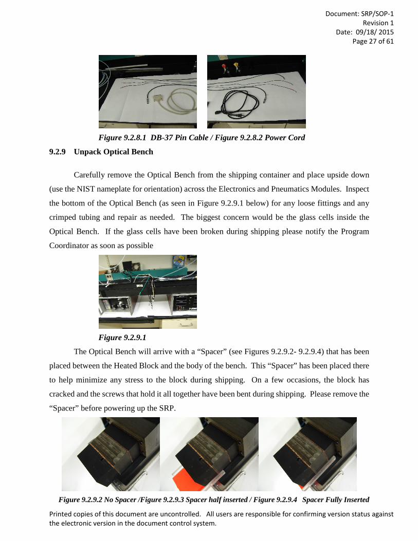
Figure 9.2.8.1 DB-37 Pin Cable / Figure 9.2.8.2 Power Cord
9.2.9 Unpack Optical Bench
Carefully remove the Optical Bench from the shipping container and place upside down
(use the NIST nameplate for orientation) across the Electronics and Pneumatics Modules. Inspect
the bottom of the Optical Bench (as seen in Figure 9.2.9.1 below) for any loose fittings and any
crimped tubing and repair as needed. The biggest concern would be the glass cells inside the
Optical Bench. If the glass cells have been broken during shipping please notify the Program
Coordinator as soon as possible
Figure 9.2.9.1
The Optical Bench will arrive with a “Spacer” (see Figures 9.2.9.2- 9.2.9.4) that has been
placed between the Heated Block and the body of the bench. This “Spacer” has been placed there
to help minimize any stress to the block during shipping. On a few occasions, the block has
cracked and the screws that hold it all together have been bent during shipping. Please remove the
“Spacer” before powering up the SRP.
Figure 9.2.9.2 No Spacer /Figure 9.2.9.3 Spacer half inserted / Figure 9.2.9.4 Spacer Fully Inserted
Document: SRP/SOP-1
Revision 1 Date: 09/18/ 2015
Page 28 of 61
Printed copies of this document are uncontrolled. All users are responsible for confirming version status against the electronic version in the document control system.
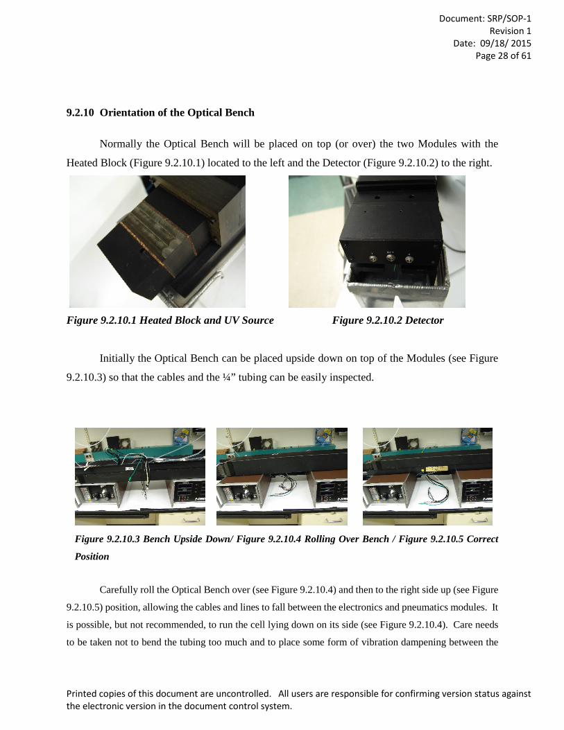
9.2.10 Orientation of the Optical Bench
Normally the Optical Bench will be placed on top (or over) the two Modules with the
Heated Block (Figure 9.2.10.1) located to the left and the Detector (Figure 9.2.10.2) to the right.
Figure 9.2.10.1 Heated Block and UV Source Figure 9.2.10.2 Detector
Initially the Optical Bench can be placed upside down on top of the Modules (see Figure
9.2.10.3) so that the cables and the ¼” tubing can be easily inspected.
Figure 9.2.10.3 Bench Upside Down/ Figure 9.2.10.4 Rolling Over Bench / Figure 9.2.10.5 Correct
Position
Carefully roll the Optical Bench over (see Figure 9.2.10.4) and then to the right side up (see Figure
9.2.10.5) position, allowing the cables and lines to fall between the electronics and pneumatics modules. It
is possible, but not recommended, to run the cell lying down on its side (see Figure 9.2.10.4). Care needs
to be taken not to bend the tubing too much and to place some form of vibration dampening between the
Document: SRP/SOP-1
Revision 1 Date: 09/18/ 2015
Page 29 of 61
Printed copies of this document are uncontrolled. All users are responsible for confirming version status against the electronic version in the document control system.
Optical Bench and the two modules. Some of the regions have a special stand for SRP-07 to use during the
Re-Verification.
Optical Bench Stand: Several types of Bench Stands are in use. EPA Las Vegas had built and
distributed several Bench Stands made of light aluminum. These Bench Stands are light weight and can be
broken down for shipping, but new Bench Stands are no longer available. EPA RTP had built a few stands
that are very solid but cannot be broken down. NIST has designed a very nice stand that can be built by
any machine shop. The NIST stand is light weight, strong and can be broken down easily and can also be
purchased from NIST. However the Optical Bench will be set up, care should be taken to buffer any
vibration between the Optical Bench and the two Modules.
9.3 Connecting the Electronic Signal Cables to SRP-07
9.3.1 Connecting the J1 Cable to the Electronics Module
No power should be supplied to SRP-07 at this time.
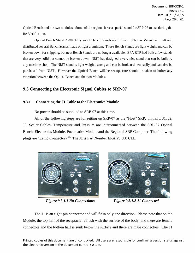
All of the following steps are for setting up SRP-07 as the “Host” SRP. Initially, J1, J2,
J3, Scalar Cables, Temperature and Pressure are interconnected between the SRP-07 Optical
Bench, Electronics Module, Pneumatics Module and the Regional SRP Computer. The following
plugs are “Lemo Connectors ©” The J1 is Part Number ERA 2S 308 CLL.
Figure 9.3.1.1 No Connections Figure 9.3.1.2 J1 Connected
The J1 is an eight-pin connector and will fit in only one direction. Please note that on the
Module, the top half of the receptacle is flush with the surface of the body, and there are female
connectors and the bottom half is sunk below the surface and there are male connectors. The J1
Document: SRP/SOP-1
Revision 1 Date: 09/18/ 2015
Page 30 of 61
Printed copies of this document are uncontrolled. All users are responsible for confirming version status against the electronic version in the document control system.
plug will need to be aligned opposite from the plug so that it will be male to female on top and
female to male on the bottom. Do not try to force the plug into the socket. If the plug does not go
directly into place, try to rotate the plug to the left or right until it falls into place. The plug will
then snap into place, and there will be a secure connection.
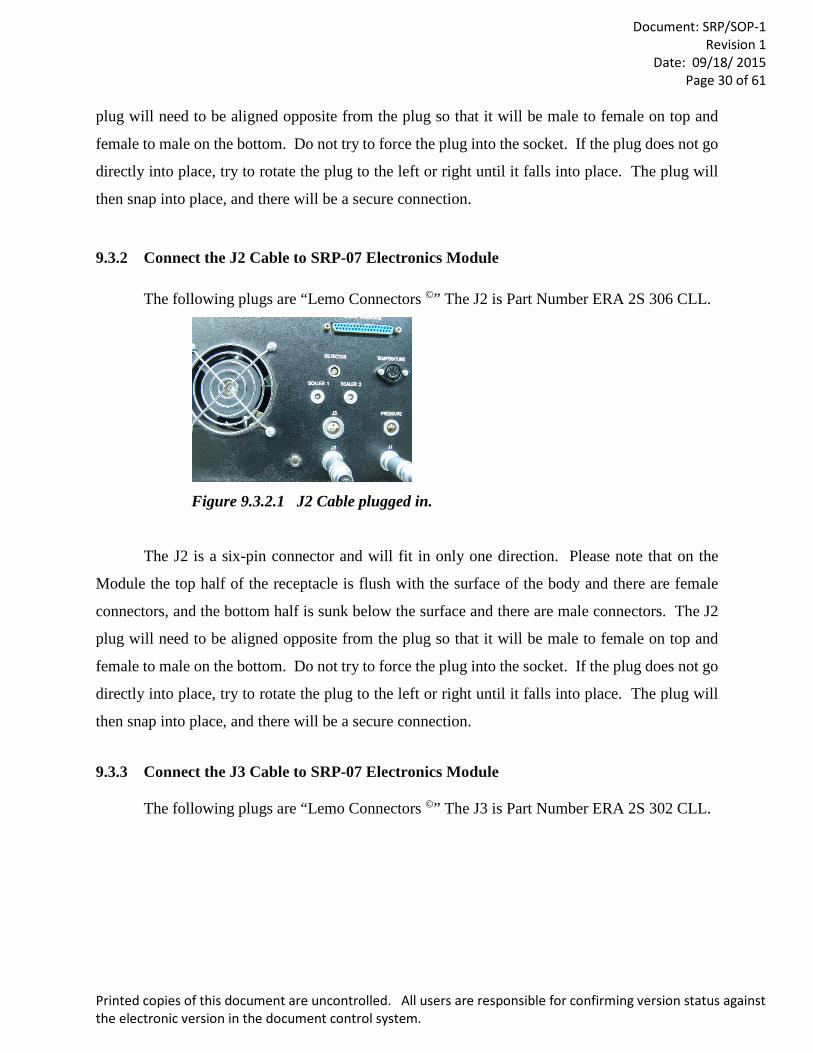
9.3.2 Connect the J2 Cable to SRP-07 Electronics Module
The following plugs are “Lemo Connectors ©” The J2 is Part Number ERA 2S 306 CLL.
Figure 9.3.2.1 J2 Cable plugged in.
The J2 is a six-pin connector and will fit in only one direction. Please note that on the
Module the top half of the receptacle is flush with the surface of the body and there are female
connectors, and the bottom half is sunk below the surface and there are male connectors. The J2
plug will need to be aligned opposite from the plug so that it will be male to female on top and
female to male on the bottom. Do not try to force the plug into the socket. If the plug does not go
directly into place, try to rotate the plug to the left or right until it falls into place. The plug will
then snap into place, and there will be a secure connection.
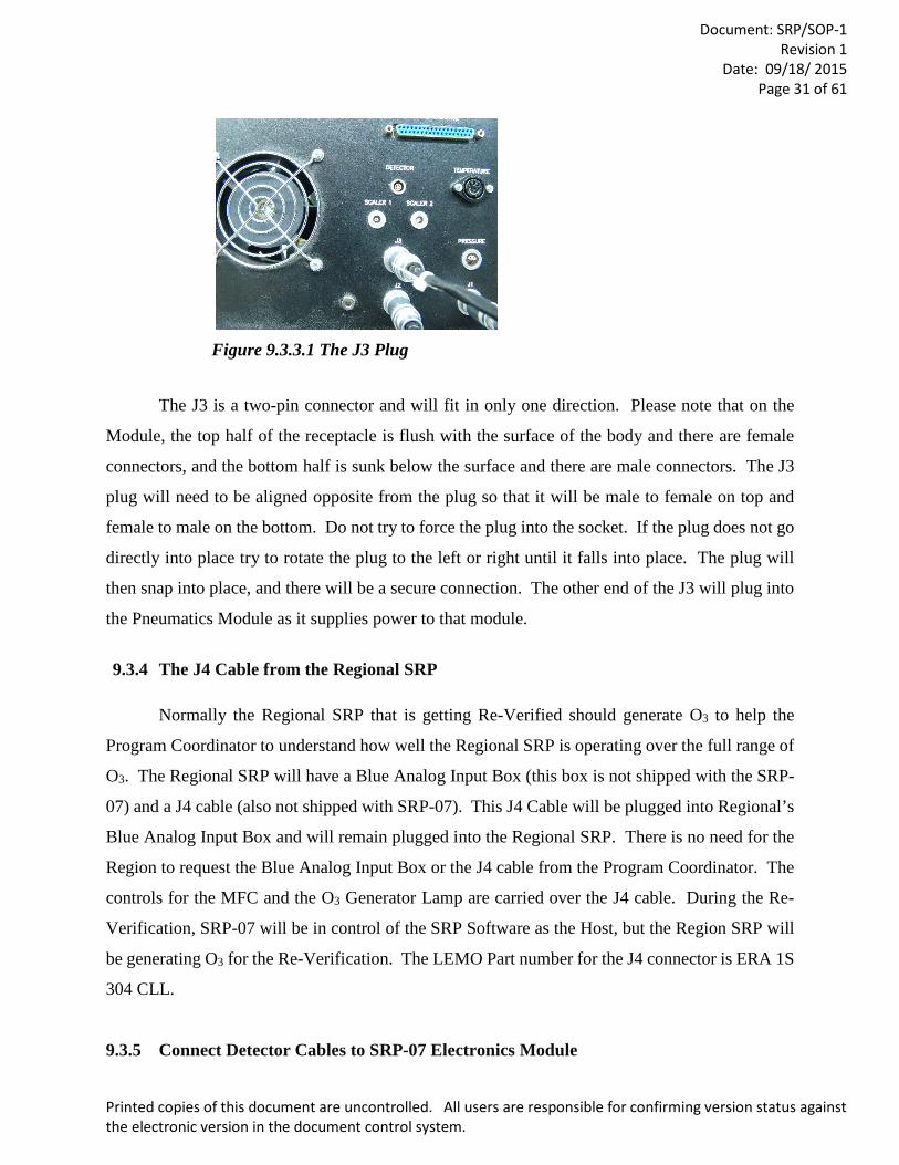
9.3.3 Connect the J3 Cable to SRP-07 Electronics Module
The following plugs are “Lemo Connectors ©” The J3 is Part Number ERA 2S 302 CLL.
Document: SRP/SOP-1
Revision 1 Date: 09/18/ 2015
Page 31 of 61
Printed copies of this document are uncontrolled. All users are responsible for confirming version status against the electronic version in the document control system.
Figure 9.3.3.1 The J3 Plug
The J3 is a two-pin connector and will fit in only one direction. Please note that on the
Module, the top half of the receptacle is flush with the surface of the body and there are female
connectors, and the bottom half is sunk below the surface and there are male connectors. The J3
plug will need to be aligned opposite from the plug so that it will be male to female on top and
female to male on the bottom. Do not try to force the plug into the socket. If the plug does not go
directly into place try to rotate the plug to the left or right until it falls into place. The plug will
then snap into place, and there will be a secure connection. The other end of the J3 will plug into
the Pneumatics Module as it supplies power to that module.
9.3.4 The J4 Cable from the Regional SRP
Normally the Regional SRP that is getting Re-Verified should generate O3 to help the
Program Coordinator to understand how well the Regional SRP is operating over the full range of
O3. The Regional SRP will have a Blue Analog Input Box (this box is not shipped with the SRP-
07) and a J4 cable (also not shipped with SRP-07). This J4 Cable will be plugged into Regional’s
Blue Analog Input Box and will remain plugged into the Regional SRP. There is no need for the
Region to request the Blue Analog Input Box or the J4 cable from the Program Coordinator. The
controls for the MFC and the O3 Generator Lamp are carried over the J4 cable. During the Re-
Verification, SRP-07 will be in control of the SRP Software as the Host, but the Region SRP will
be generating O3 for the Re-Verification. The LEMO Part number for the J4 connector is ERA 1S
304 CLL.
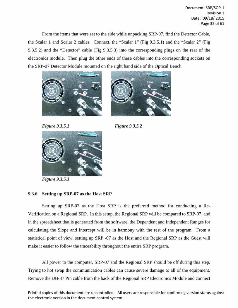
9.3.5 Connect Detector Cables to SRP-07 Electronics Module
Document: SRP/SOP-1
Revision 1 Date: 09/18/ 2015
Page 32 of 61
Printed copies of this document are uncontrolled. All users are responsible for confirming version status against the electronic version in the document control system.
From the items that were set to the side while unpacking SRP-07, find the Detector Cable,
the Scalar 1 and Scalar 2 cables. Connect, the “Scalar 1” (Fig 9.3.5.1) and the “Scalar 2” (Fig
9.3.5.2) and the “Detector” cable (Fig 9.3.5.3) into the corresponding plugs on the rear of the
electronics module. Then plug the other ends of these cables into the corresponding sockets on
the SRP-07 Detector Module mounted on the right hand side of the Optical Bench.
Figure 9.3.5.1 Figure 9.3.5.2
Figure 9.3.5.3
9.3.6 Setting up SRP-07 as the Host SRP
Setting up SRP-07 as the Host SRP is the preferred method for conducting a Re-
Verification on a Regional SRP. In this setup, the Regional SRP will be compared to SRP-07, and
in the spreadsheet that is generated from the software, the Dependent and Independent Ranges for
calculating the Slope and Intercept will be in harmony with the rest of the program. From a
statistical point of view, setting up SRP -07 as the Host and the Regional SRP as the Guest will
make it easier to follow the traceability throughout the entire SRP program.
All power to the computer, SRP-07 and the Regional SRP should be off during this step.
Trying to hot swap the communication cables can cause severe damage to all of the equipment.
Remove the DB-37 Pin cable from the back of the Regional SRP Electronics Module and connect
Document: SRP/SOP-1
Revision 1 Date: 09/18/ 2015
Page 33 of 61
Printed copies of this document are uncontrolled. All users are responsible for confirming version status against the electronic version in the document control system.
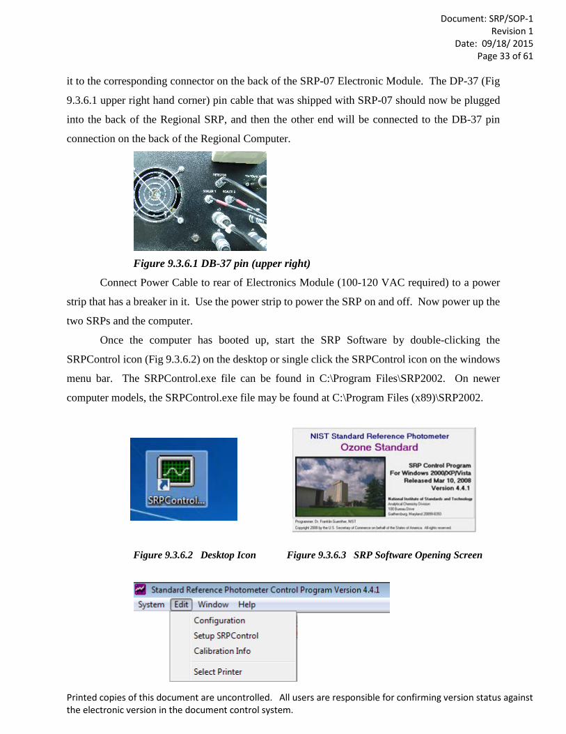
it to the corresponding connector on the back of the SRP-07 Electronic Module. The DP-37 (Fig
9.3.6.1 upper right hand corner) pin cable that was shipped with SRP-07 should now be plugged
into the back of the Regional SRP, and then the other end will be connected to the DB-37 pin
connection on the back of the Regional Computer.
Figure 9.3.6.1 DB-37 pin (upper right)
Connect Power Cable to rear of Electronics Module (100-120 VAC required) to a power
strip that has a breaker in it. Use the power strip to power the SRP on and off. Now power up the
two SRPs and the computer.
Once the computer has booted up, start the SRP Software by double-clicking the
SRPControl icon (Fig 9.3.6.2) on the desktop or single click the SRPControl icon on the windows
menu bar. The SRPControl.exe file can be found in C:\Program Files\SRP2002. On newer
computer models, the SRPControl.exe file may be found at C:\Program Files (x89)\SRP2002.
Figure 9.3.6.2 Desktop Icon Figure 9.3.6.3 SRP Software Opening Screen
Document: SRP/SOP-1
Revision 1 Date: 09/18/ 2015
Page 34 of 61
Printed copies of this document are uncontrolled. All users are responsible for confirming version status against the electronic version in the document control system.
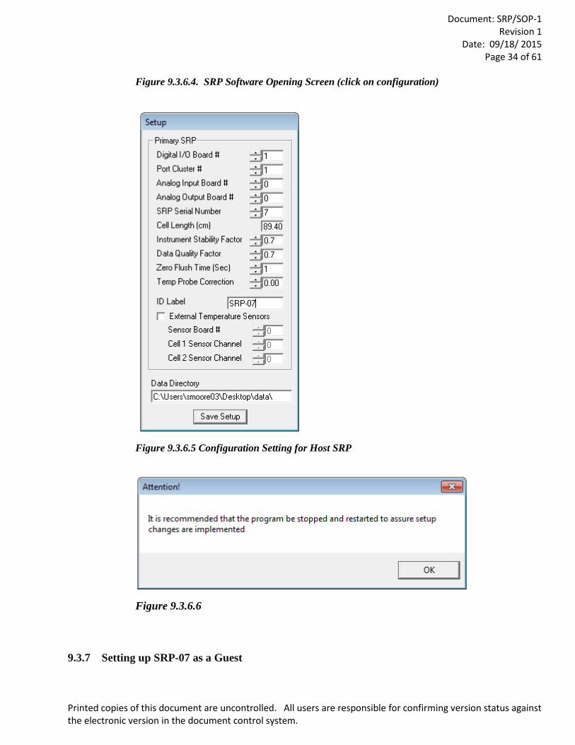
Figure 9.3.6.4. SRP Software Opening Screen (click on configuration)
Figure 9.3.6.5 Configuration Setting for Host SRP
Figure 9.3.6.6
9.3.7 Setting up SRP-07 as a Guest
Document: SRP/SOP-1
Revision 1 Date: 09/18/ 2015
Page 35 of 61
Printed copies of this document are uncontrolled. All users are responsible for confirming version status against the electronic version in the document control system.
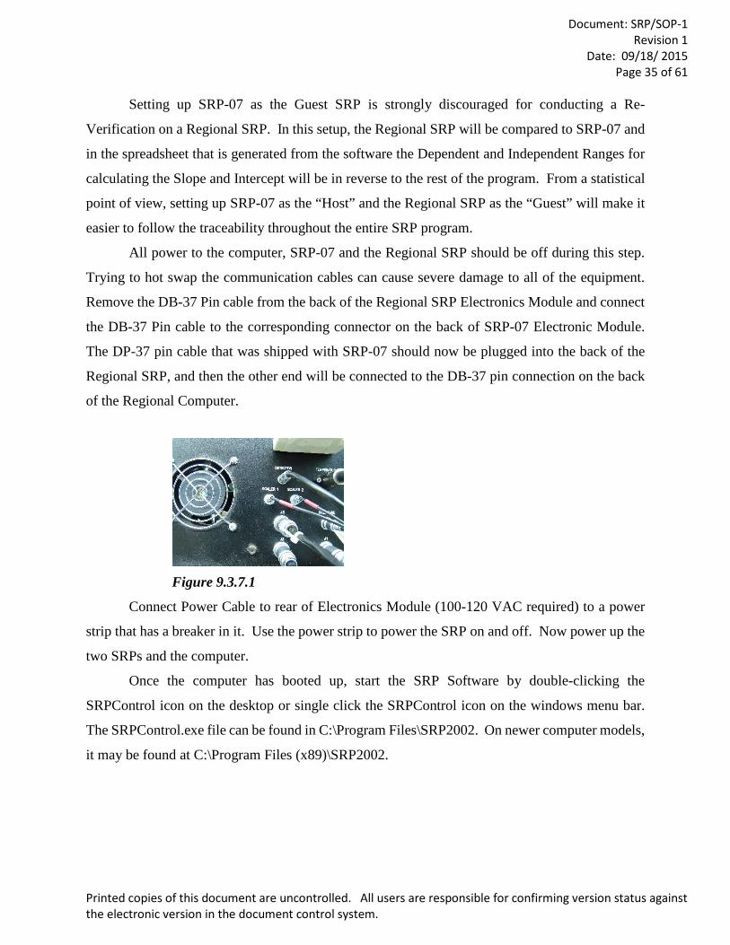
Setting up SRP-07 as the Guest SRP is strongly discouraged for conducting a Re-
Verification on a Regional SRP. In this setup, the Regional SRP will be compared to SRP-07 and
in the spreadsheet that is generated from the software the Dependent and Independent Ranges for
calculating the Slope and Intercept will be in reverse to the rest of the program. From a statistical
point of view, setting up SRP-07 as the “Host” and the Regional SRP as the “Guest” will make it
easier to follow the traceability throughout the entire SRP program.
All power to the computer, SRP-07 and the Regional SRP should be off during this step.
Trying to hot swap the communication cables can cause severe damage to all of the equipment.
Remove the DB-37 Pin cable from the back of the Regional SRP Electronics Module and connect
the DB-37 Pin cable to the corresponding connector on the back of SRP-07 Electronic Module.
The DP-37 pin cable that was shipped with SRP-07 should now be plugged into the back of the
Regional SRP, and then the other end will be connected to the DB-37 pin connection on the back
of the Regional Computer.
Figure 9.3.7.1
Connect Power Cable to rear of Electronics Module (100-120 VAC required) to a power
strip that has a breaker in it. Use the power strip to power the SRP on and off. Now power up the
two SRPs and the computer.
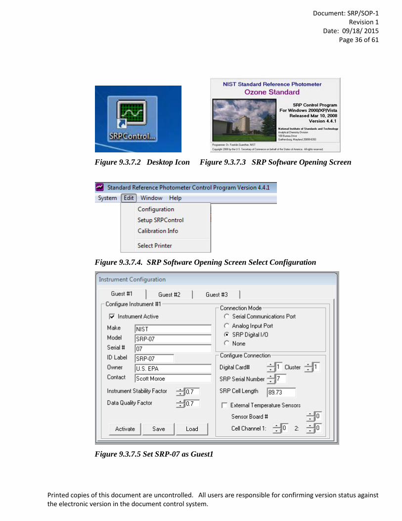
Once the computer has booted up, start the SRP Software by double-clicking the
SRPControl icon on the desktop or single click the SRPControl icon on the windows menu bar.
The SRPControl.exe file can be found in C:\Program Files\SRP2002. On newer computer models,
it may be found at C:\Program Files (x89)\SRP2002.
Document: SRP/SOP-1
Revision 1 Date: 09/18/ 2015
Page 36 of 61
Printed copies of this document are uncontrolled. All users are responsible for confirming version status against the electronic version in the document control system.
Figure 9.3.7.2 Desktop Icon Figure 9.3.7.3 SRP Software Opening Screen
Figure 9.3.7.4. SRP Software Opening Screen Select Configuration
Figure 9.3.7.5 Set SRP-07 as Guest1
Document: SRP/SOP-1
Revision 1 Date: 09/18/ 2015
Page 37 of 61
Printed copies of this document are uncontrolled. All users are responsible for confirming version status against the electronic version in the document control system.
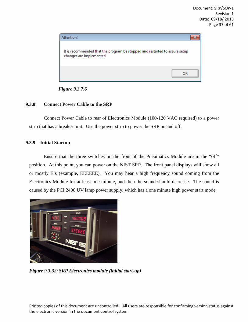
Figure 9.3.7.6
9.3.8 Connect Power Cable to the SRP
Connect Power Cable to rear of Electronics Module (100-120 VAC required) to a power
strip that has a breaker in it. Use the power strip to power the SRP on and off.
9.3.9 Initial Startup
Ensure that the three switches on the front of the Pneumatics Module are in the “off”
position. At this point, you can power on the NIST SRP. The front panel displays will show all
or mostly E’s (example, EEEEEE). You may hear a high frequency sound coming from the
Electronics Module for at least one minute, and then the sound should decrease. The sound is
caused by the PCI 2400 UV lamp power supply, which has a one minute high power start mode.
Figure 9.3.3.9 SRP Electronics module (initial start-up)
Document: SRP/SOP-1
Revision 1 Date: 09/18/ 2015
Page 38 of 61
Printed copies of this document are uncontrolled. All users are responsible for confirming version status against the electronic version in the document control system.
9.4 Pneumatics Connection Setup
9.4.1. Remove Caps and Plugs
Remove the caps and plugs from the Teflon tubing and the pneumatics module and save
for re-packing.
9.4.2 Connecting the Teflon Lines
Connect the Teflon lines labeled “To 1" and “To 2" to the Teflon bulkhead connectors on
the rear of the Pneumatics Module labeled “To Cell 1" and “To Cell 2".
For the Teflon lines that are connected to stainless steel Swagelok fittings, ensure they are
hand-tightened plus a quarter inch turn with a wrench. For the Teflon lines that are connected to
the Teflon Swagelok fittings, ensure they are hand-tightened. (Be careful not to strip the threads
of the Teflon fittings.)
9.4.3 Identifying the Correct Cell Lines
The cable tie markers attached to the Teflon lines sometimes break off. When one of the
regional SRPs comes to RTP for repair or maintenance, the external Teflon tubing will be replaced
and a label will be put on the end of the tubing to identify where it will be connected. If the labels
should fall off, the operator will need to identify where the proper connections are. First, connect
any tubing that is properly identified and through the process of elimination, the others may fall
into place. If some or all of the markings have fallen off, the operator will need to identify the Cell
1 and Cell 2 lines. As you look at the Optical Bench, the Temperature Block and UV Source
should be to your left and the detector to your right. The Scalars are matched with the Cells, that
is, Scalar one is Cell one and Scalar 2 is Cell 2. Underneath the Cell Block to your left, there are
two Teflon lines coming out. The “To Cell One” is towards the front, closest to you, and then “To
Cell Two” is towards the back. Go ahead and connect “To Cell One” to the appropriate Teflon
bulkhead fitting on the back of the back of the SRP-07 Pneumatics Module.
Document: SRP/SOP-1
Revision 1 Date: 09/18/ 2015
Page 39 of 61
Printed copies of this document are uncontrolled. All users are responsible for confirming version status against the electronic version in the document control system.
9.4.4 Connecting the Stainless Steel (SS) Fittings to SRP-07 Pneumatics Module
Connect one of the SS fittings from the cells to the SS bulkhead label 1 on the back of the
Pneumatics Module, but only hand tighten. Connect the Sample and Reference lines to the
manifold at this time. Now watch the rotameter on the front panel for Cell 1 (the one to the left),
and turn the sample pump on for just a moment. If the glass ball in the rotameter jumps, the
connection is correct If the glass ball in the rotameter does not jump, then switch to the other SS
fitting from the cell and repeat. Rotameter 1 should now work.
9.4.5 Connecting the Teflon Fittings to SRP-07 Pneumatics Module
Connect the Teflon lines labeled “1" and “2" to the stainless steel bulkhead connectors on
the rear of the Pneumatics Module labeled “From 1" and “From 2".
9.4.6 Connecting the Zero Air to SRP-07 Pneumatics Module
Connect the laboratory supply of zero air to the stainless steel bulkhead connector labeled
“Air In”. The pressure of this line must be kept between 15 and 30 psi. An adequate Zero Air
Generator should be able to supply up to 30 liters per minute at 35 psi. Most any brand-named
Zero Air generator should work well.
9.4.7 Technical Note on Zero Air Systems
A note should be mentioned here about the commonly used AADCO 737 Zero Air
Generator. During the scrubbing process, the AADCO Zero Air Generator will alternately scrub
out the O2 and N2 and then re-mix them alternately. This process causes the O3 concentration to
alternate between high and then low. Therefore, when generating a high O3 concentration, you
could end up with undesired stability issues. The solution is an optional part from AADCO called
a Mixer/Receiver that will remix the O2 and N2 at stable concentrations.
9.4.8 Verification Check of Zero Air Source
If problems with your Zero Air are suspected, a check that can be done to verify your Zero
Document: SRP/SOP-1
Revision 1 Date: 09/18/ 2015
Page 40 of 61
Printed copies of this document are uncontrolled. All users are responsible for confirming version status against the electronic version in the document control system.
air supply would be to buy a commercial tank of Ultra-Pure air and set up a purge line directly to
the manifold and replace either the “reference in” or the “Ozone In” and then run some zero
readings from the two different sources. If you get an unusually high or low Zero, then there is an
issue. If the Zero is 0 ± 0.2 ppb, then the air supply should be adequate. This test should be
performed at least once per year.
9.4.9 NIST Recommendation for Zero Air used for an SRP
NIST recommends the zero air generator have a minimum input pressure of 15 psig (34.7
psia, 239.2 kPa) of clean dry air, preferably zero air, containing no significant impurities, having
less than 1 ppb total hydrocarbons by volume, and containing 20–21 % oxygen. The NIST SRP
has internal devices to control the amount of air required for operation. No external control is
necessary. A zero air supply of 20 standard liters/min (sLpm) will be adequate for most verification
work. These units are available through commercial suppliers of air monitoring equipment. An
SRP draws 2 sLpm into each cell (4 sLpm total), plus some excess is required in the sample and
reference manifolds, and additional flow requirements for instruments under calibration.
9.4.10 CFR Statement on Zero Air
CFR 50 Appendix D Section 4.1 defines Zero Air as follows: “The zero air must be free of
contaminants which would cause a detectable response from the O3 analyzer, and it should be free
of NO, C2H4, and other species which react with O3. A procedure for generating suitable zero air
is given in Reference 9. As shown in Figure 1, the zero air supplied to the photometer cell for the
I0 reference measurement must be derived from the same source as the zero air used for generation
of the O3 concentration to be assayed (I measurement). When using the photometer to certify a
transfer standard having its own source of O3, see Reference 8 for guidance on meeting this
requirement.”
9.4.11 The SRP Glass Manifold
The Dual Glass Manifold is separate from the SRP Pneumatics Module. Care should be
taken to locate the Pneumatics Module as close to the Manifold as possible, taking care not to kink

Document: SRP/SOP-1
Revision 1 Date: 09/18/ 2015
Page 41 of 61
Printed copies of this document are uncontrolled. All users are responsible for confirming version status against the electronic version in the document control system.
any of the Teflon tubing. Then connect the Sample and Reference lines to the Manifold. SRP-07
may be used to generate O3. Zero Air would only need to be supplied to the SRP that would be
generating O3. To convert flow and O3 control over to SRP-07, simply unplug the J4 from the host
SRP and plug it into the back of the Pneumatics Module on SRP-07. If control does not
automatically take place, it will be necessary to restart the SRP Control Software and in some
cases, the computer and the SRPs may need to be rebooted. Figure 9.4.11.1 is a schematic of the
Dual Glass Manifold. NIST has modified their Manifold to be approximately 1/8” larger inner
diameter. In some areas, the #15 SLV Thread may not be available, so another thread size would
be acceptable, but all new Solid Caps and Caps with ¼” Aperture would need to be ordered with
the Manifold.
Figure 9.4.11.1 Dual glass manifold schematic
9.4.12 SRP Warm-Up Time
Plug in the power cable and place the power switch on the electronics module in the “on”
position. Allow the SRP an initial warmup time period of at least four hours for the system to
become fully stable. Normally the SRP would be left on after the initial setup with the modules
kept in idle mode (with the pump switch in “off” position) until needed for a verification or any
routine system characteristics data checks. It is recommended that a power strip be used for turning
Document: SRP/SOP-1
Revision 1 Date: 09/18/ 2015
Page 42 of 61
Printed copies of this document are uncontrolled. All users are responsible for confirming version status against the electronic version in the document control system.
the SRP on and leaving the power switch in the on position. The power toggle on the SRP is
slightly under-rated for the equipment; a newer version will soon be available to all the operators.
9.5 SRP-07 Standard Operating Procedure 9.5.1 Procedure and SRP Control Software
The following is the procedure for running SRP-07 (the host) against a Regional SRP (the guest).
However, the principles apply equally to any other Guest instrument that is brought in to a Region for
Qualification, Verification or Re-Verification. Any references to the NIST SRP Control Software will be
kept to a minimum for two reasons. The first reason is to keep this document from becoming too large
and too difficult to handle. The second reason is that the software will be written up in a separate SOP,
detailing commercial instrument setups in more detail and more detailed information on various
parameters of the software.
9.5.2. QC Checks
9.5.2.1 Data Sheet
Before running a Qualification, Verification, Re-Verification, Audit Level Comparisons or a Zero –
Span, a QC Check on the SRP needs to be performed. The frequency of the QC Checks could be referenced
to the International Standards Organization (ISO) 17025 definition of determining the time span in-
between calibrations by establishing a historical record of intervals needed to keep a current calibration
without having to make adjustments. The Pressure and Temperature circuits have a tendency to drift ever
so slightly over a period of two to three days. Therefore, it is essential to run the QA/QC as often as
possible, even daily. Section 9.6 contains an example of the Excel QA Check Sheet.
9.5.2.2 Title Heading
In the heading of the QA check, enter the current Date, SRP Serial Number, the Location of the SRP,
the Ambient Room Temperature and the name of the analyst who will be conducting the tests. In the
current QA Spreadsheet, some of these functions can be invoked by clicking on a box or selecting from a
drop down menu (see QA SRP FORMAT.xls). The QA spreadsheet will be in an Excel Spreadsheet with
macros added in to help automate the QA process. Additionally, the QA spreadsheet will assist the SRP
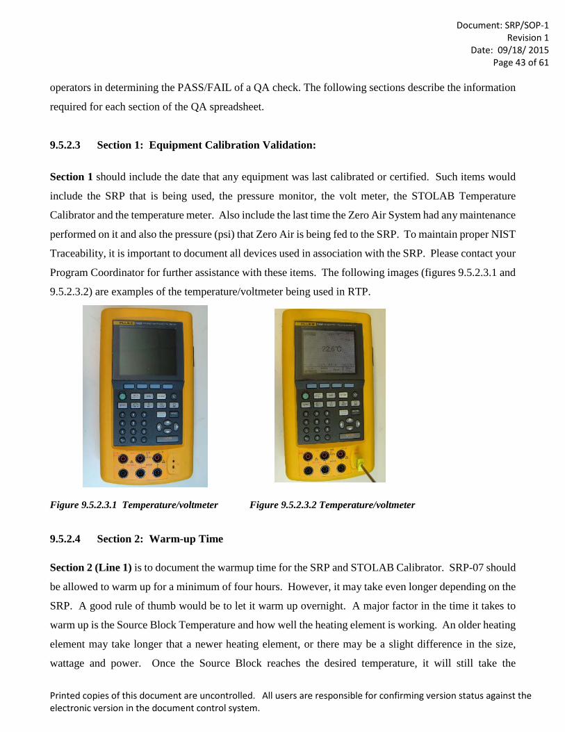
Document: SRP/SOP-1
Revision 1 Date: 09/18/ 2015
Page 43 of 61
Printed copies of this document are uncontrolled. All users are responsible for confirming version status against the electronic version in the document control system.
operators in determining the PASS/FAIL of a QA check. The following sections describe the information
required for each section of the QA spreadsheet.
9.5.2.3 Section 1: Equipment Calibration Validation:
Section 1 should include the date that any equipment was last calibrated or certified. Such items would
include the SRP that is being used, the pressure monitor, the volt meter, the STOLAB Temperature
Calibrator and the temperature meter. Also include the last time the Zero Air System had any maintenance
performed on it and also the pressure (psi) that Zero Air is being fed to the SRP. To maintain proper NIST
Traceability, it is important to document all devices used in association with the SRP. Please contact your
Program Coordinator for further assistance with these items. The following images (figures 9.5.2.3.1 and
9.5.2.3.2) are examples of the temperature/voltmeter being used in RTP.
Figure 9.5.2.3.1 Temperature/voltmeter Figure 9.5.2.3.2 Temperature/voltmeter
9.5.2.4 Section 2: Warm-up Time
Section 2 (Line 1) is to document the warmup time for the SRP and STOLAB Calibrator. SRP-07 should
be allowed to warm up for a minimum of four hours. However, it may take even longer depending on the
SRP. A good rule of thumb would be to let it warm up overnight. A major factor in the time it takes to
warm up is the Source Block Temperature and how well the heating element is working. An older heating
element may take longer that a newer heating element, or there may be a slight difference in the size,
wattage and power. Once the Source Block reaches the desired temperature, it will still take the
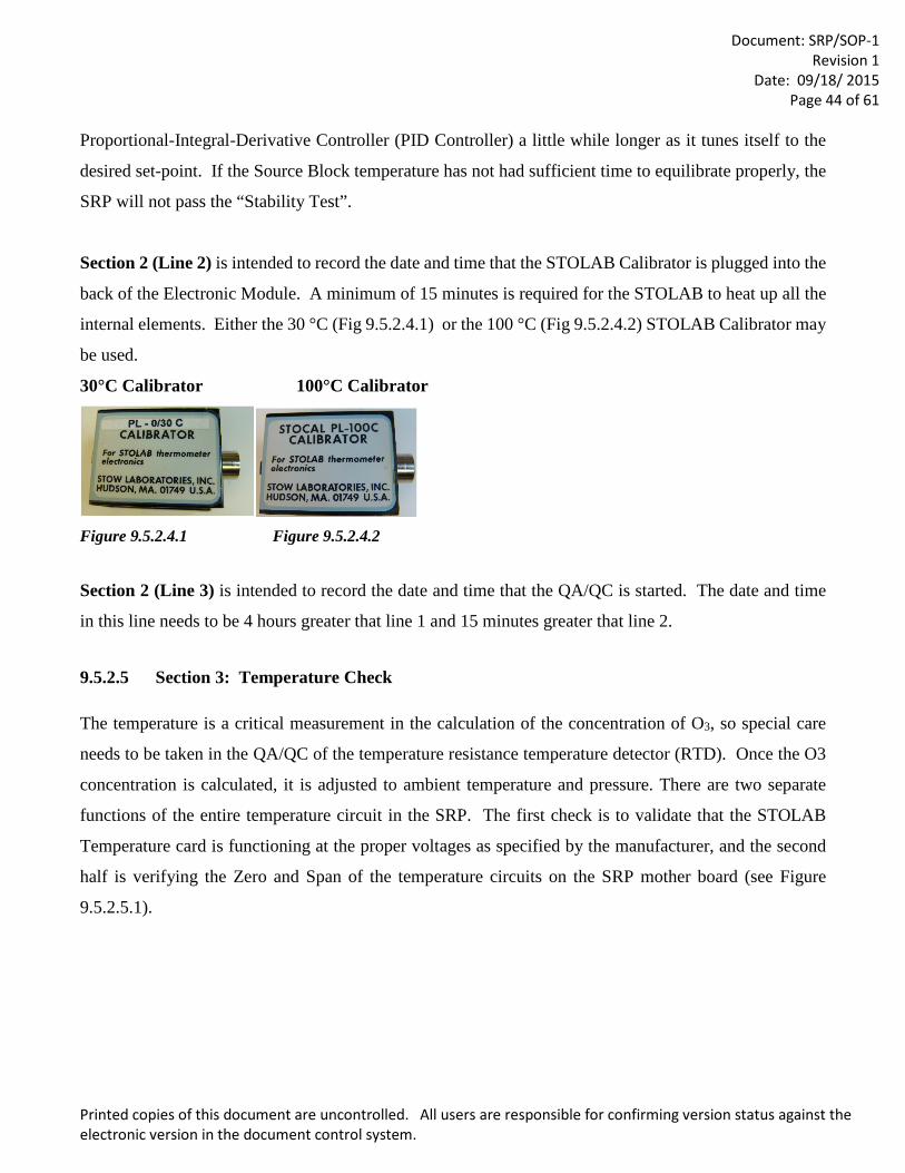
Document: SRP/SOP-1
Revision 1 Date: 09/18/ 2015
Page 44 of 61
Printed copies of this document are uncontrolled. All users are responsible for confirming version status against the electronic version in the document control system.
Proportional-Integral-Derivative Controller (PID Controller) a little while longer as it tunes itself to the
desired set-point. If the Source Block temperature has not had sufficient time to equilibrate properly, the
SRP will not pass the “Stability Test”.
Section 2 (Line 2) is intended to record the date and time that the STOLAB Calibrator is plugged into the
back of the Electronic Module. A minimum of 15 minutes is required for the STOLAB to heat up all the
internal elements. Either the 30 °C (Fig 9.5.2.4.1) or the 100 °C (Fig 9.5.2.4.2) STOLAB Calibrator may
be used.
30°C Calibrator 100°C Calibrator
Figure 9.5.2.4.1 Figure 9.5.2.4.2
Section 2 (Line 3) is intended to record the date and time that the QA/QC is started. The date and time
in this line needs to be 4 hours greater that line 1 and 15 minutes greater that line 2.
9.5.2.5 Section 3: Temperature Check
The temperature is a critical measurement in the calculation of the concentration of O3, so special care
needs to be taken in the QA/QC of the temperature resistance temperature detector (RTD). Once the O3
concentration is calculated, it is adjusted to ambient temperature and pressure. There are two separate
functions of the entire temperature circuit in the SRP. The first check is to validate that the STOLAB
Temperature card is functioning at the proper voltages as specified by the manufacturer, and the second
half is verifying the Zero and Span of the temperature circuits on the SRP mother board (see Figure
9.5.2.5.1).
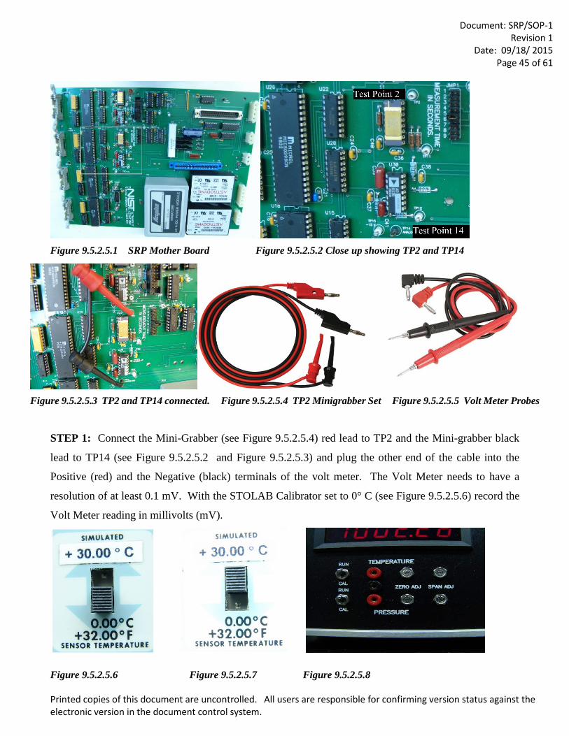
Document: SRP/SOP-1
Revision 1 Date: 09/18/ 2015
Page 45 of 61
Printed copies of this document are uncontrolled. All users are responsible for confirming version status against the electronic version in the document control system.
Figure 9.5.2.5.1 SRP Mother Board Figure 9.5.2.5.2 Close up showing TP2 and TP14
Figure 9.5.2.5.3 TP2 and TP14 connected. Figure 9.5.2.5.4 TP2 Minigrabber Set Figure 9.5.2.5.5 Volt Meter Probes
STEP 1: Connect the Mini-Grabber (see Figure 9.5.2.5.4) red lead to TP2 and the Mini-grabber black
lead to TP14 (see Figure 9.5.2.5.2 and Figure 9.5.2.5.3) and plug the other end of the cable into the
Positive (red) and the Negative (black) terminals of the volt meter. The Volt Meter needs to have a
resolution of at least 0.1 mV. With the STOLAB Calibrator set to 0° C (see Figure 9.5.2.5.6) record the
Volt Meter reading in millivolts (mV).
Figure 9.5.2.5.6 Figure 9.5.2.5.7 Figure 9.5.2.5.8
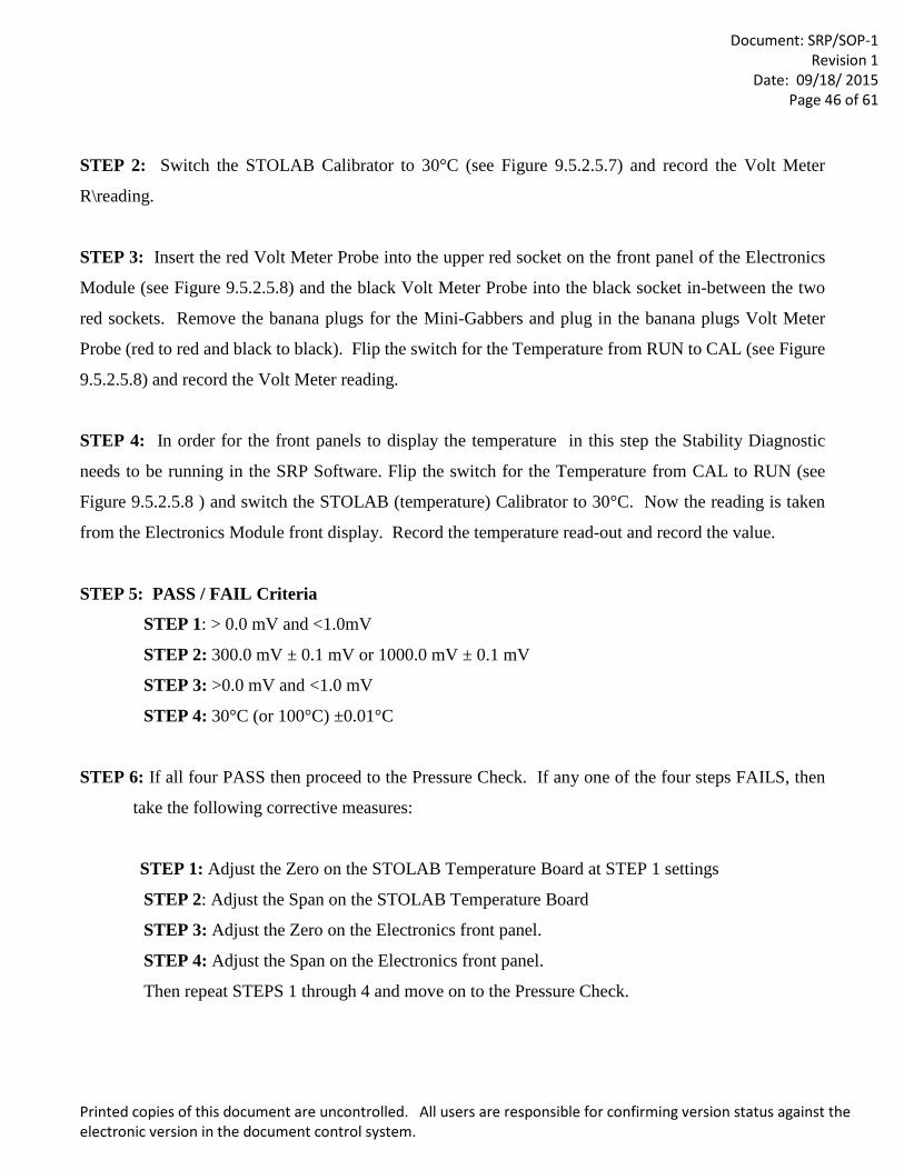
Document: SRP/SOP-1
Revision 1 Date: 09/18/ 2015
Page 46 of 61
Printed copies of this document are uncontrolled. All users are responsible for confirming version status against the electronic version in the document control system.
STEP 2: Switch the STOLAB Calibrator to 30°C (see Figure 9.5.2.5.7) and record the Volt Meter
R\reading.
STEP 3: Insert the red Volt Meter Probe into the upper red socket on the front panel of the Electronics
Module (see Figure 9.5.2.5.8) and the black Volt Meter Probe into the black socket in-between the two
red sockets. Remove the banana plugs for the Mini-Gabbers and plug in the banana plugs Volt Meter
Probe (red to red and black to black). Flip the switch for the Temperature from RUN to CAL (see Figure
9.5.2.5.8) and record the Volt Meter reading.
STEP 4: In order for the front panels to display the temperature in this step the Stability Diagnostic
needs to be running in the SRP Software. Flip the switch for the Temperature from CAL to RUN (see
Figure 9.5.2.5.8 ) and switch the STOLAB (temperature) Calibrator to 30°C. Now the reading is taken
from the Electronics Module front display. Record the temperature read-out and record the value.
STEP 5: PASS / FAIL Criteria
STEP 1: > 0.0 mV and <1.0mV
STEP 2: 300.0 mV ± 0.1 mV or 1000.0 mV ± 0.1 mV
STEP 3: >0.0 mV and <1.0 mV
STEP 4: 30°C (or 100°C) ±0.01°C
STEP 6: If all four PASS then proceed to the Pressure Check. If any one of the four steps FAILS, then
take the following corrective measures:
STEP 1: Adjust the Zero on the STOLAB Temperature Board at STEP 1 settings
STEP 2: Adjust the Span on the STOLAB Temperature Board
STEP 3: Adjust the Zero on the Electronics front panel.
STEP 4: Adjust the Span on the Electronics front panel.
Then repeat STEPS 1 through 4 and move on to the Pressure Check.
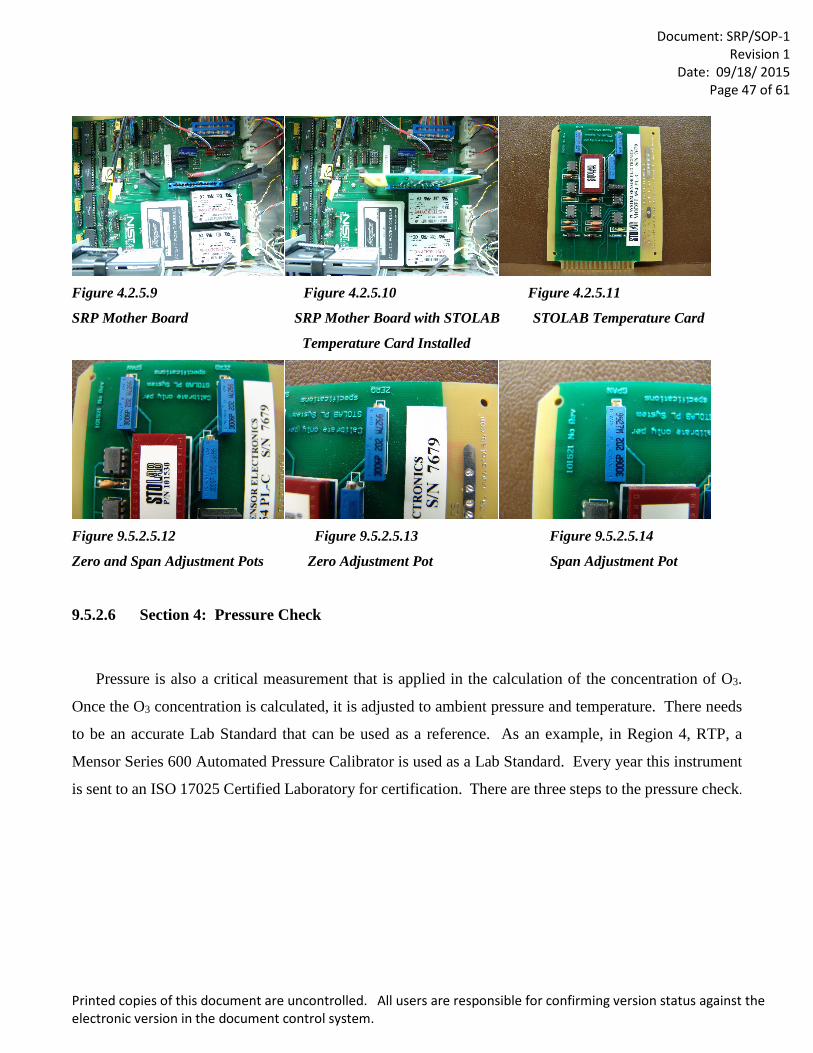
Document: SRP/SOP-1
Revision 1 Date: 09/18/ 2015
Page 47 of 61
Printed copies of this document are uncontrolled. All users are responsible for confirming version status against the electronic version in the document control system.
Figure 4.2.5.9 Figure 4.2.5.10 Figure 4.2.5.11
SRP Mother Board SRP Mother Board with STOLAB STOLAB Temperature Card
Temperature Card Installed
Figure 9.5.2.5.12 Figure 9.5.2.5.13 Figure 9.5.2.5.14
Zero and Span Adjustment Pots Zero Adjustment Pot Span Adjustment Pot
9.5.2.6 Section 4: Pressure Check
Pressure is also a critical measurement that is applied in the calculation of the concentration of O3.
Once the O3 concentration is calculated, it is adjusted to ambient pressure and temperature. There needs
to be an accurate Lab Standard that can be used as a reference. As an example, in Region 4, RTP, a
Mensor Series 600 Automated Pressure Calibrator is used as a Lab Standard. Every year this instrument
is sent to an ISO 17025 Certified Laboratory for certification. There are three steps to the pressure check.
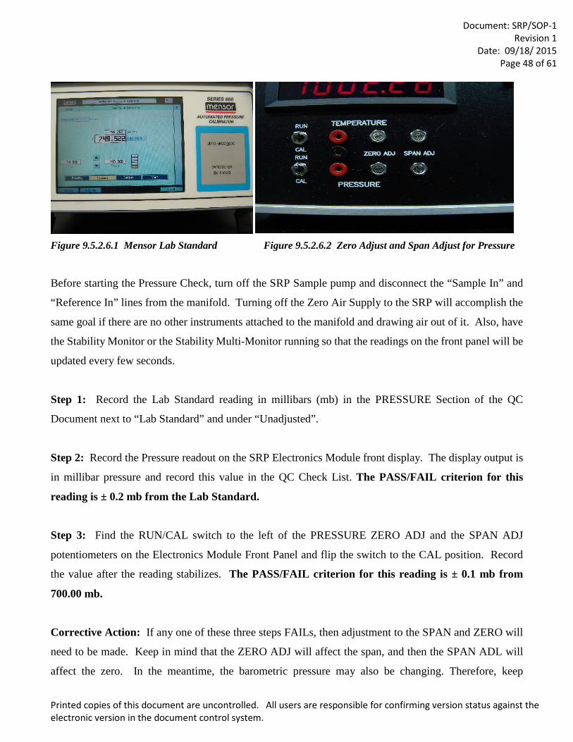
Document: SRP/SOP-1
Revision 1 Date: 09/18/ 2015
Page 48 of 61
Printed copies of this document are uncontrolled. All users are responsible for confirming version status against the electronic version in the document control system.
Figure 9.5.2.6.1 Mensor Lab Standard Figure 9.5.2.6.2 Zero Adjust and Span Adjust for Pressure
Before starting the Pressure Check, turn off the SRP Sample pump and disconnect the “Sample In” and
“Reference In” lines from the manifold. Turning off the Zero Air Supply to the SRP will accomplish the
same goal if there are no other instruments attached to the manifold and drawing air out of it. Also, have
the Stability Monitor or the Stability Multi-Monitor running so that the readings on the front panel will be
updated every few seconds.
Step 1: Record the Lab Standard reading in millibars (mb) in the PRESSURE Section of the QC
Document next to “Lab Standard” and under “Unadjusted”.
Step 2: Record the Pressure readout on the SRP Electronics Module front display. The display output is
in millibar pressure and record this value in the QC Check List. The PASS/FAIL criterion for this
reading is ± 0.2 mb from the Lab Standard.
Step 3: Find the RUN/CAL switch to the left of the PRESSURE ZERO ADJ and the SPAN ADJ
potentiometers on the Electronics Module Front Panel and flip the switch to the CAL position. Record
the value after the reading stabilizes. The PASS/FAIL criterion for this reading is ± 0.1 mb from
700.00 mb.
Corrective Action: If any one of these three steps FAILs, then adjustment to the SPAN and ZERO will
need to be made. Keep in mind that the ZERO ADJ will affect the span, and then the SPAN ADL will
affect the zero. In the meantime, the barometric pressure may also be changing. Therefore, keep
Document: SRP/SOP-1
Revision 1 Date: 09/18/ 2015
Page 49 of 61
Printed copies of this document are uncontrolled. All users are responsible for confirming version status against the electronic version in the document control system.
referencing the Lab Standard, the SPAN and the ZERO to make adjustment using the potentiometers for
the PRESSURE on the front panel. Try adjusting the ZERO first and then move back to the SPAN. It
will be necessary to move back and forth several times for it to pass, but once it does pass, repeat steps 1
through 3, record the values and move on to the next section.
9.5.2.7 Section 5: UV Source Lamp and Block Temperature
Section 5 is the area where the Ultraviolet (UV) lamps are documented, and the temperature of the
heated block is recorded. Two different lamps are used in each SRP: the UV Source Lamp and the O3
Generator Lamp. The temperature for the Source Lamp Heated Block is located on the Watlow PID
Controller inside the Electronic Module. The temperature for the O3 Generator Heated Block is inside the
Pneumatics Module. Ensure that the temperature readout is the same as the set point. If they are not
within ±0.1°C, then that may be an indication of a problem or the heated blocks have not reached the set
point. Failure to reach the set point can lead to stability issues that will be discussed in Section 8. A future
version of the/ QC Work Sheet will also include the date that each lamp was installed. The O3 Generator
Heated Block temperature is usually kept a little lower because the block is located right next to the MFC
and temperature will not significantly affect the stability of O3 generation. There are no PASS/FAIL
criteria for these temperature settings other than that they need to be stable.
9.5.2.8 Section 6: Total Scalar Counts
If the Stability program is running, this would be a good time to stop it and record the Scalars from
Cell 1 and Cell 2. Each Cell has a UV Detector that measures the intensity of the UV light being
transmitted through the Cell. The more O3 that is in the Cell, the lower the Scalar count will be. As the
UV Light hits the detector, the detector will respond with a frequency. The more UV light, the higher the
frequency. The SRP will then sum the frequency, at a given Hertz (Hz) for a total of five seconds. The
summed frequencies of the given Hertz is the value that will be displayed on Scalars 1 and 2. The
PASS/FAIL criteria for the Scalars should be >100,000 and <250,000. There are three methods that
can be used to increase the Scalar Counts.
The first method is to adjust the potentiometer on the O3 card to apply more power to the lamp. Two
styles of boards are seen in Figures 9.5.2.8.1-9.5.2.8.3, below. Find the blue potentiometer on the board

Document: SRP/SOP-1
Revision 1 Date: 09/18/ 2015
Page 50 of 61
Printed copies of this document are uncontrolled. All users are responsible for confirming version status against the electronic version in the document control system.
and turn it so that the Scalars move up. The stability should be running during the adjustment. If the
scalar counts do not increase sufficiently, then the next method to try is to replace the UV Lamp. And
finally, if those two methods do not increase the scalar counts sufficiently, it may be time to replace the
board.
Figure 9.5.2.8.1 Old Style Board Figure 9.5.2.8. 2 New Style Board Figure 9.5.2.8.3 close up
9.5.2.9 Section 7: Dark Counts
To check the dark counts, start with the SRP Control Software in the Standby Mode. On the SRP
control panel, click on the “SHUUER” button, and you should hear the shutter close. Then start the
“Stability” or “Multi-Stability” Diagnostic Tool. The Dark Count will then be displayed on the front panel
of the SRP and on the computer screen. Record the Scalar Counts for the Cells on the QA sheet. Proceed
with the adjustment of the Dark Counts by adjusting the potentiometers on the top of the detector. The
software will run the Dark Count Stability test for only 10 to 15 minutes before it will abort the run.
Restart the Dark Count Stability again if more time is needed. The acceptance criteria for the Dark Counts
are >5 and <25 counts. In some labs where Relative Humidity may fluctuate throughout the day, you may
want to add a packet of desiccant to the bottom of the detector or add a small purge line of Zero Air to
flush the detector to help stabilize the Dark Counts.
9.5.2.10 Section 8: Stability Test Once all the QA Checks have passed, the Stability Test needs to be run. The Stability test will run only
one SRP at a time, where the Multi-Stability can run up to four SRPs at a time. In the Stability test, 20
repetitions will be averaged together and a total of 10 cycles will be run.
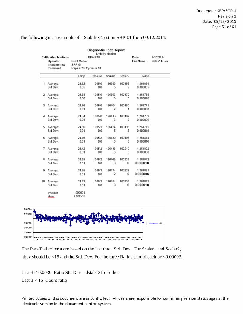
Document: SRP/SOP-1
Revision 1 Date: 09/18/ 2015
Page 51 of 61
Printed copies of this document are uncontrolled. All users are responsible for confirming version status against the electronic version in the document control system.
The following is an example of a Stability Test on SRP-01 from 09/12/2014:
The Pass/Fail criteria are based on the last three Std. Dev. For Scalar1 and Scalar2,
they should be <15 and the Std. Dev. For the three Ratios should each be <0.00003.
Last 3 < 0.0030 Ratio Std Dev dstab131 or other
Last 3 < 15 Count ratio
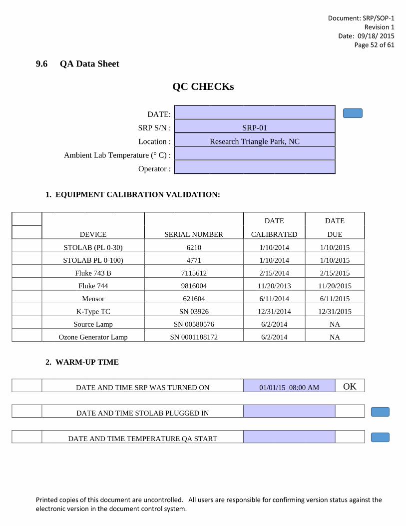
Document: SRP/SOP-1
Revision 1 Date: 09/18/ 2015
Page 52 of 61
Printed copies of this document are uncontrolled. All users are responsible for confirming version status against the electronic version in the document control system.
9.6 QA Data Sheet
QC CHECKs
DATE:
SRP S/N : SRP-01 Location : Research Triangle Park, NC Ambient Lab Temperature (° C) : Operator :
1. EQUIPMENT CALIBRATION VALIDATION:
DEVICE SERIAL NUMBER
DATE DATE CALIBRATED DUE
STOLAB (PL 0-30) 6210 1/10/2014 1/10/2015 STOLAB PL 0-100) 4771 1/10/2014 1/10/2015 Fluke 743 B 7115612 2/15/2014 2/15/2015 Fluke 744 9816004 11/20/2013 11/20/2015 Mensor 621604 6/11/2014 6/11/2015 K-Type TC SN 03926 12/31/2014 12/31/2015 Source Lamp SN 00580576 6/2/2014 NA Ozone Generator Lamp SN 0001188172 6/2/2014 NA
2. WARM-UP TIME
DATE AND TIME SRP WAS TURNED ON 01/01/15 08:00 AM OK DATE AND TIME STOLAB PLUGGED IN
DATE AND TIME TEMPERATURE QA START
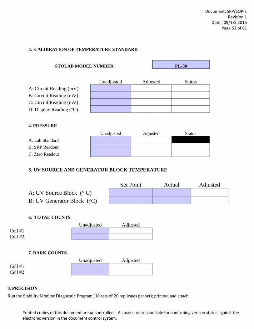
Document: SRP/SOP-1
Revision 1 Date: 09/18/ 2015
Page 53 of 61
Printed copies of this document are uncontrolled. All users are responsible for confirming version status against the electronic version in the document control system.
3. CALIBRATION OF TEMPERATURE STANDARD
STOLAB MODEL NUMBER PL-30
Unadjusted Adjusted Status A: Circuit Reading (mV) B: Circuit Reading (mV) C: Circuit Reading (mV) D: Display Reading (°C)
4. PRESSURE
Unadjusted Adjusted Status A: Lab Standard B: SRP Readout C: Zero Readout
5. UV SOURCE AND GENERATOR BLOCK TEMPERATURE
Set Point Actual Adjusted A: UV Source Block (° C) B: UV Generator Block (°C)
6. TOTAL COUNTS
Unadjusted Adjusted Cell #1 Cell #2
7. DARK COUNTS
Unadjusted Adjusted Cell #1 Cell #2
8. PRECISION
Run the Stability Monitor Diagnostic Program (10 sets of 20 replicates per set); printout and attach.
Document: SRP/SOP-1
Revision 1 Date: 09/18/ 2015
Page 54 of 61
Printed copies of this document are uncontrolled. All users are responsible for confirming version status against the electronic version in the document control system.
9.7 Re-Verification Procedure
9.7.1 The Re-Verification may begin after all the QC Checks have passed. (see section 9.5.2 QC Checks)
9.7.2 Check the Temperature and make sure the RTD is plugged in and not the STOWLAB Calibrator. Also check the Temperature calibration switch on the front panel of the Electronics Module is in the “UP” position.
9.7.3 Check the Pressure calibration switch on the front panel of the Electronics Module is in the “UP” position.
9.7.4 Plug the J-4 cable into the back of the pneumatics module of the SRP that will be generating Ozone. Preferably the regional SRP that is being Re-Verified should generate Ozone, however SRP-07 could also be used.
9.7.5 Connect the Sample Output line from the Ozone Generating SRP to the bottom of the “Sample” side of the manifold.
9.7.6 Connect the Reference Output line from the Ozone Generating SRP to the bottom of the “Reference” side of the manifold.
9.7.7 Connect the Sample lines from both of the SRPs to the upper ports of the “Sample” side of the manifold.
9.7.8 Connect the Reference line from both of the SRPs to the upper ports of the “Reference” side of the manifold.
9.7.9 Turn on the Zero Air to the SRP that will be generating Ozone. Operating pressure should 15 to 25 pounds per square inch of pressure.
9.7.10 Turn on the Flow Controller Power located on the front of the Pneumatics Module of the SRP that will be suppling Ozone. The power to the Mass Flow Controller should never be ON when there is no Zero Air being supplied to the SRP.
9.7.11 Turn on the Ozone Generator Lamp Power located on the front of the Pneumatics Module of the SRP that will be suppling Ozone.
9.7.12 Inside the Pneumatics Module, on the right hand side, there are two switches that allow the computer to control the Mass Flow Controller and the Power to the UV Lamp in the generator. Make sure that both are in the “ON” position.
9.7.13 Shut down any other software that may be open (this includes any Excel spreadsheets).
9.7.14 Shut down the SRP Control Program. (System <ENTER>, Exit <ENTER>)
9.7.15 Restart the SRP Control Program.
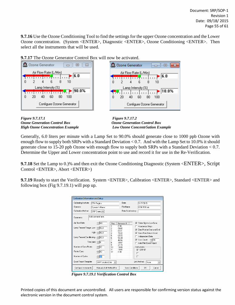
Document: SRP/SOP-1
Revision 1 Date: 09/18/ 2015
Page 55 of 61
Printed copies of this document are uncontrolled. All users are responsible for confirming version status against the electronic version in the document control system.
9.7.16 Use the Ozone Conditioning Tool to find the settings for the upper Ozone concentration and the Lower Ozone concentration. (System <ENTER>, Diagnostic <ENTER>, Ozone Conditioning <ENTER>. Then select all the instruments that will be used.
9.7.17 The Ozone Generator Control Box will now be activated.
Figure 9.7.17.1 Figure 9.7.17.2 Ozone Generation Control Box Ozone Generation Control Box High Ozone Concentration Example Low Ozone Concentr5ation Example Generally, 6.0 liters per minute with a Lamp Set to 90.0% should generate close to 1000 ppb Ozone with enough flow to supply both SRPs with a Standard Deviation < 0.7. And with the Lamp Set to 10.0% it should generate close to 15-20 ppb Ozone with enough flow to supply both SRPs with a Standard Deviation < 0.7. Determine the Upper and Lower concentration point to use and record it for use in the Re-Verification.
9.7.18 Set the Lamp to 0.)% and then exit the Ozone Conditioning Diagnostic (System <ENTER>, Script Control <ENTER>, Abort <ENTER>)
9.7.19 Ready to start the Verification. System <ENTER>, Calibration <ENTER>, Standard <ENTER> and following box (Fig 9.7.19.1) will pop up.
Figure 9.7.19.1 Verification Control Box
Document: SRP/SOP-1
Revision 1 Date: 09/18/ 2015
Page 56 of 61
Printed copies of this document are uncontrolled. All users are responsible for confirming version status against the electronic version in the document control system.
9.7.19.1 Calibration Institute: Please use EPA Region #. City and state may also be included. 9.7.19.2 Operator: Please include the Operator’s full name. 9.7.19.3 Calibration Method: Once a method is generated for Re-Verifying an SRP a copy can be saved and used again later on. 9.7.19.3 DATE: Current date is automatically entered. 9.7.19.4 File Name: File name is automatically entered.
9.7.19.5 Data Subdirectory: The subdirectory automatically defaults the “Data” directory. However an
alternate subdirectory may be entered here at the operator’s discretion. 9.7.19.6 Comments: Please4 enter any comments such as which SRP is generation Ozone or any repairs or
annual maintenance performed prior to the Re-Verification. 9.7.19.7 Air Flow Rate: 6.0 liter per minute is recommended for two SRPs. The excess flow from the
Sample and Reference Manifold should be verified with a rotometer to make sure there is at least 1.0 liters per minute excess flow.
9.7.19.8 Lamp Percentage Range – Low: Use the Low Range established from the Ozone Conditioning
Control Box (see Section 9.7.15 above) or from a recent Verification. 9.7.19.9 Lamp Percentage Range – High: Use the High Range established from the Ozone Conditioning
Control Box (see Section 9.7.15 above) or from a recent Verification. 9.7.19.10 Lamp Percent Conditioning: Generally use the same value for the Lamp Percentage Range –
High used above (9.7.17.9). 9.7.19.11 Time (min): Set to zero if conditioning is not required. If new tubing or a new pump were recently
installed, then running the conditioning for 15-30 minutes would be required. 9.7.19.12 Number of Conc Points: To maintain consistency across all the EPA Regions select 12
concentration points. With the “Zero Point at Start and End Box” checked this would be 10 actual concentration points and two Zero points.
9.7.19.13 Points/Conc: This the number of concentration points that are averaged together to complete a
calibration step. To maintain consistency across all the EPA Regions select 10.
9.7.19.14 Number of Cycles: Set this value for the maximum of 20 cycles and allow the Verification to run
overnight. Each cycle will take about two hours. Allowing it to run overnight at least 6 cycles or more. The minimum for an SRP Verification is 6 cycles. The Step/Generator% List to the right will automatically calculate even step for each concentration point. Specific concentration s are not required for a Verification.
Document: SRP/SOP-1
Revision 1 Date: 09/18/ 2015
Page 57 of 61
Printed copies of this document are uncontrolled. All users are responsible for confirming version status against the electronic version in the document control system.
9.7.19.15 Excel Report Template: Default templates are found in C:/Program Files/SRP2002/Templates
or C:/Program Files (x86)/SRP2002/Templates. Open SRPTemplate-A4.xls and edit cell A2 to “Verification Report”. In all three Guest pages. Save the file as “Verification.xls” and use this file as the default report for all Verifications.
9.7.19.16 Order High to Low Conc: Check the box. 9.7.19.17 Randomize Steps: For an SRP Verification leave this box unchecked. 9.7.19.18 Zero Point at Start and End: Check the box. 9.7.19.19 Independent Data: For manual data entry thei box would be checked, but for automatic data entry
leave this box unchecked. 9.7.19.19 Instruments: Check the SRP-07 box and any other instrument that applies. 9.7.19.20 Link Method: Leave unchecked.
9.7.19.21 Save Conditions: Clicking on this button will prompt you to save the method. The method can be
saved over an existing method or a new method name can be saved. 9.7.19.22 OK: Selecting this button will begin the Verification.
9.7.20 Allow the Verification to run overnight for a minimum of six complete cycles.
9.7.21 Copy all the data runs, QC Checks and Stability to an E-mail and send it to RTP for data validation.
9.7.22 Once a Summary Report has been received from RTP documenting that the Regional SRP has passed its annual Verification, then SRP-07 may be boxed up and returned to RTP. With the summary Report there will also be the last Verification of SRP-07 and a copy of the last NIST Verification. These reports should be saved and provided to any guest Verification upon request.
10. Data Records and Management
The RTP and Regional SRP operators are responsible for creating, retaining, and maintaining the forms
and reports generated by the use of the SRP in comparison to the traveling SRP, and in the comparison to the
state, local, tribal and CASTNET ozone primary standards that are required to be compared to the SRPs every
year. Along with the QA Data Sheet described in Section 9.6, a verification report, like the example in Figure
10.2 is required to be developed and saved as evidence of an acceptable verification.
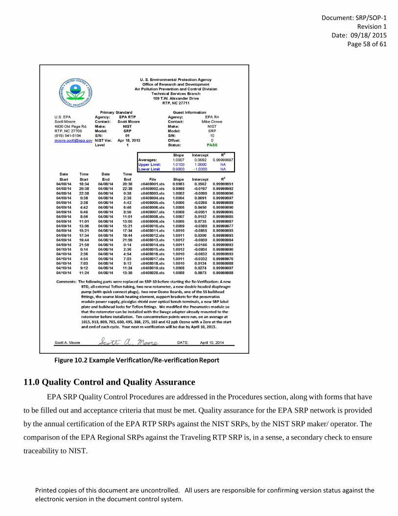
Document: SRP/SOP-1
Revision 1 Date: 09/18/ 2015
Page 58 of 61
Printed copies of this document are uncontrolled. All users are responsible for confirming version status against the electronic version in the document control system.
11.0 Quality Control and Quality Assurance EPA SRP Quality Control Procedures are addressed in the Procedures section, along with forms that have
to be filled out and acceptance criteria that must be met. Quality assurance for the EPA SRP network is provided
by the annual certification of the EPA RTP SRPs against the NIST SRPs, by the NIST SRP maker/ operator. The
comparison of the EPA Regional SRPs against the Traveling RTP SRP is, in a sense, a secondary check to ensure
traceability to NIST.
Document: SRP/SOP-1
Revision 1 Date: 09/18/ 2015
Page 59 of 61
Printed copies of this document are uncontrolled. All users are responsible for confirming version status against the electronic version in the document control system.
12.0 References
12.1 Guidance for Requirements and Use of the EPA SRP Network
Technical Assistance Document (TAD) for Transfer Standards for Calibration of Air Monitoring Analyzers for O3, October 2013 http://www.epa.gov/ttn/amtic/qapollutant.html. Every reference of this acronym in this SOP applies directly to the document EPA-454/B-13-004.
12.2 Physical Basis of the Photometry Equation The theory of photometric measurement is very well documented. This portion of the SOP is a guide
to the existing documentation, and the reader may follow these links for a deeper understanding of how
the SRP calculates the O3 concentrations. The first place to begin any research on the photometry equation
is in the Code of Federal Regulations, and that resource is easily available on line. The following is a list
of contents and a web link to all the chapters that pertain to the theory of photometric measurement. The
link :http://www.ecfr.gov/cgi-bin/text-idx?tpl=/ecfrbrowse/Title40/40tab_02.tpl
e-CFR 40 CFR PART 50—NATIONAL PRIMARY AND SECONDARY AMBIENT AIR QUALITY STANDARDS
§50.9 National 1-hour primary and secondary ambient air quality standards for O3.
§50.10 National 8-hour primary and secondary ambient air quality standards for O3.
Appendix D to Part 50—Measurement Principle and Calibration Procedure for the Measurement of O3 in the
Atmosphere
Appendices H,I, P and U of Part 50 address Interpretation of the 1 and 8-Hour Primary and Secondary
National Ambient Air Quality Standards for O3
Additionally this information is periodically updated. Revisions to the ozone standard, including the
Appendix (D) in 40 CFR Part 50 for Ozone, which address the requirements for ozone standard
traceability to NIST SRPs, including the addition of recently updated ozone guidance documents, have
been proposed. They can be viewed at the following website:
http://www.gpo.gov/fdsys/pkg/FR-2014-12-17/pdf/2014-28674.pdf
The text of interest is near the very end of the proposed revisions,
Document: SRP/SOP-1
Revision 1 Date: 09/18/ 2015
Page 60 of 61
Printed copies of this document are uncontrolled. All users are responsible for confirming version status against the electronic version in the document control system.
12.3 Sources of Error in the Photometry Principle
The following references deal with systematic errors and biases of the NIST SRP.
Bass, A.M.. 1977. Ultraviolet photometer for ozone calibration.
Smith. 1986. Standard Reference Photometer Network for Verification and Certification of Ozone
Standard.
Paur, R.J., Bass, A.M., Norris, J.E., and Buckley, T.J. (Date Unknown) Standard Reference Photometer
for the assay of O3 in calibration atmospheres” Document Number NISTIR 6963.
Norris, J., Guenther, F.R., (NIST), Wielgosz, R.I., Viallon, J., Moussay, P., (BIPM), Braganza, E.,
Klamser-Williams,T. (EPA-Las Vegas). NIST Standard Reference Photometer Operations Manual.
Document Number “Draft”
Viallon, P., Moussay, F.R., Guenther,F., and Wielgosz, R.I.. 2006. A study of systematic biases and
measurement uncertainties in O3 mole fraction measurements with the NIST Standard Reference
Photometer” doi: 10.1088/0026-1394/43/5/016 Metrologia 43 (2006) 441-450
Laiva, M.A. 2011. Uncertainty of ozone measurements with the primary standard reference photometer
(SRP 45), Talanta, Volume 86, pages 71-81,
Mosquin, P.L.et al. 2011. A model for the estimation of ozone photometer Aggregate Uncertainty for
EPA’s NIST Traceability Program. Paper 2011-A-580-AWMA, Presented at Annual meeting.
Norris, J. 2013. Temperature measurement and optical path-length bias improvement modifications to
National Institute of Standards and Technology ozone reference standards.
12.4 Upgrades of the NIST SRP Hardware and Software
Document: SRP/SOP-1
Revision 1 Date: 09/18/ 2015
Page 61 of 61
Printed copies of this document are uncontrolled. All users are responsible for confirming version status against the electronic version in the document control system.
Norris, J.E., Band, A., Bliss, R., and Guenther, F. 2004. Upgrade and intercomparison of the US Environmental Protection Agencies ozone reference standards. AWMA Paper # 04-A-530-AWMA,
Norris, J.E., Choquette, S., Viallon, J., Moussay, P., Wielgosz,R., and Guenther, F. 2013. Temperature measurement and optical path-length bias improvement modifications to National Institute of Standards and Technology ozone reference standards.
12.5 International Photometric Measurements for O3
The following references are provided for those readers who may want to see published information on the international work on the SRP. As NIST has provided, and continues to provide new SRPS to many of the countries in the world (some have more than one), they have asked the government organization of France (Bureau Internationale des Poids et Measurements, abbreviated the BIPM) that has the parallel role to NIST for that country, to be the international lead on the SRP.
Klausen, J., Zellweger, C., Buchmann, B., and Hofer, P. 2003. Uncertainty and Bias of Surface O3
Measurements at Selected Global Atmosphere Watch Sites. Journal of Geophysical Research, Vol. 108,
No. D19, 4622, doi:10.1029/2003JD003710, 2003
Sweeney,B.P., Milton,M.J.T., Butterfield, D.M., and Woods, P.T. 2002 (© Crown Copyright 2001).
Intercomparison of National O3 Primary Standards V1.6. Report on Results of Euromet Project 414
Wielgosz, R.L,* Viallon, J.,* Novak, J.,** and Vokoun, M.,*** 2002. Comparison of O3 Reference
Standards of the CHGMI and the BIPM. Bureau International des Poids et Mésures, F-92312 Cedex
** Czech Hydrometeorological Institute, Prague, Czech Republic.
Viallon, J., 1*, Moussay, P.,1, Esler, M.,1, Wielgosz, R., 1, Bremser, W., 2, Novák, J., 3, Vokoun, M., 3,
Botha, A., 4, Van Rensburg, M.J., 4, Zellweger, C., 5, Goldthorp, S., 6, Borowiak, A., 7, Lagler, F., 7,
Walden, J., 8, Malgeri, E., 9, Sassi, M.P.,9, Gomez, P.M., 10, Patier, R.F., 10, Madruga, D.G., 10, Woo,
J.-C., 11, Kim, Y.D., 11, Macé, T., 12, Sutour, C., 12, Surget, A., 12, Niederhauser, B., 13, Schwaller,
D., 13, Frigy, B., 14, Váraljai, I.G., 14, Hashimoto, S., 15, Mukai1, H., Tanimoto, H., 15, Ahleson, H.P.,
16, Egeløv, A., 16, Ladegård, N.,17, Marsteen, L., 17, Tørnkvist, K., 17, Guenther, F.R., 18, Norris, J.E.,
18, Hafkenscheid, T.L., 19, Van Rijn, M.M., 19, Quincey, P., 20, Sweeney, B., 20, Langer, S., 21,
Magnusson, B., 21, Bastian, J., 22,Stummer, V., 22, Fröhlich, M., 23, Wolf, A., 23, Konopelko, L. A., 24,
Kustikov, Y.A., 24,Rumyanstev, D.V., 242006. International Comparison CCQM-P28, O3 at ambient
level (Pilot study)