Embed Size (px)
Citation preview
G EK-14772A
INSTRUCTIONS
STATIC EXCITER-REGULATOR
EQUIPMENT
3S7501FS141
GEK-147’72
TABLE OF CONTENTS
INTRODUCTION ........................................................
RECEIVING, HANDLING, AND STORAGE .................................. Receiving and Handling ................................................ Storage ...............................................................
DESCRIPTION ........................................................... Component Arrangement ............................................... Static Magnetic Power Components and Power Rectifiers .................. Silicon Diode Fundamentals ............................................ Automatic Voltage Regulator ........................................... Manual Voltage Regulator .............................................. Control Equipment Operation ........................................... CT and PT Burdens ...................................................
INSTALLATION ......................................................... Location and Mounting ................................................. Connections .......................................................... Polarity and Phase Rotation ............................................
INITIAL OPERATION, TEST, AND ADJUSTMENT .......................... Control Circuits ...................................................... Static Exciter ......................................................... Gain Measurements .................................................... System Self -Compensation ............................................ Under excited Reactive Ampere Limit ...................................
MAINTENANCE ......................................................... PPT and SCT’s ........................................................ Static Equipment ...................................................... Other Equipment ......................................................
RENEWAL PARTS .......................................................
TROUBLESHOOTING .....................................................
PAGE 3
i 3
: a a
11
11 11 11 11
11 11 11 13 13 13
16 16 17 17
17
ia
These instructions do not purport to cover all details or variations in equipment nor to provide for every possible contingency to be met in connection with installation, operation or maintenance. Should further information be desired or should particular problems arise which are not covered sufficiently for the purchaser’s purposes. the matter should be referred to the General Electric Company.
GEK-14772
STATIC EXCITER-REGULATOR EQUIPMENT FOR GAS TURBINE PACKAGE POWER PLANT
INTRODUCTION The silicon-controlled rectifier @CR) Static Exciter - Regulator equipment performs its regulation and ex- citation function by monitoring AC machine line volt - age and current and producing the proper excitation conditions required by the machine.
The power potential transformer (PPT) and saturable current transformers (XT’s) are the main source of power for the AC machine field; at no load all field power is obtained from the PPT while both supply power at full load with the SCT’s supplying most of the power. The power from these two units is rectified by the three- phase full-wave bridge rectifier and then applied to the field of the AC machine. The currents in the primaries of the SCT’s provide some inherent self-regulation. Theorectically, this self -regulation should completely compensate for load changes, however, AC machine saturation, field heating, and other secondary effects make it necessary to add more compensation. This extra compensation is obtained by saturating the SCT’s with a DC control winding current. The amount of DC required is obtained from the automatic regulator whose input continuously monitors line current and voltage when in the automatic mode operation. Also, a manual control of the DC control winding is provided.
A reactive current compensator is included to permit ’ proper division of reactive current between paralleled machines. Also included is a start-up circuit for field flashing, voltage adjusters for local control of the auto- matic and manual regulators, field suppression relay (when an optional AC machine field breaker is not used), and other components to assure proper operation.
Refer to the diagrams provided with the equipment to determine what material is included and what con- nections should be used. The diagrams shown in this book are for illustrative purposes only; they are not intended to apply to all installations.
RECEIVING, HANDLING AND STORAGE
RECEIVING AND HANDLING
Immediately upon receipt, the equipment should be carefully unpacked to avoid damaging the apparatus. Particular care should be exercised to prevent small parts being mislaid or thrown away in the packing material.
As soon as the equipment is unpacked it should be ex- amined for any damage that might have been sustained in transit. If injury or rough handling is evident, a damage claim shall be filed immediately with the trans- portation company and the nearest General Electric Sales Office should be notified promptly.
STORAGE
If the equipment is not to be used as soon as it is un- packed, it should be stored in a clean dry place and protected from accidental damage. Particular care should be exercised to avoid storing the equipment in locations where construction wtrk is in progress.
DESCRIPTION
COMPONENT ARRANGEMENT
The static exciter-regulator consists of the following:
A. Equipment mounted in the exciter compartment:
1. 3S7501FS Rectifier assembly consisting of a three:-&-&: full-wave bridge rectifier, shunt, shaft voltage suppressor circuit and Thyrite* resistors. This welded angle-fram? assembly is floor mounted.
2. Three 44A------ Resistor assembleies (one resistor in parallel with y SCT control winding and one resistor in parallel with the SCT suppression winding for each assembly.)
3. One floor-mounted three-phase power poten- tial transformer. This step-down trans- former supplies power for the AC machine field and the regulator.
4. Three floor-mounted single-phase saturable current transformers. These transformers also supply power to the AC machine field.
5. Three single-phase linear reactors.
B. ’ Equipment mounted in the control cab:
1. 3s7931------ Regulator panel which contains local-control automatic regulator voltage ad- juster, and regulator reset pushbutton.
2. 387932------ DC Control panel, which contains start-up relay and circuit, field suppression relay and local control DC regulator voltage adjusters.
STATIC MAGNETIC POWER COMPONENTS AND POWER RE-S
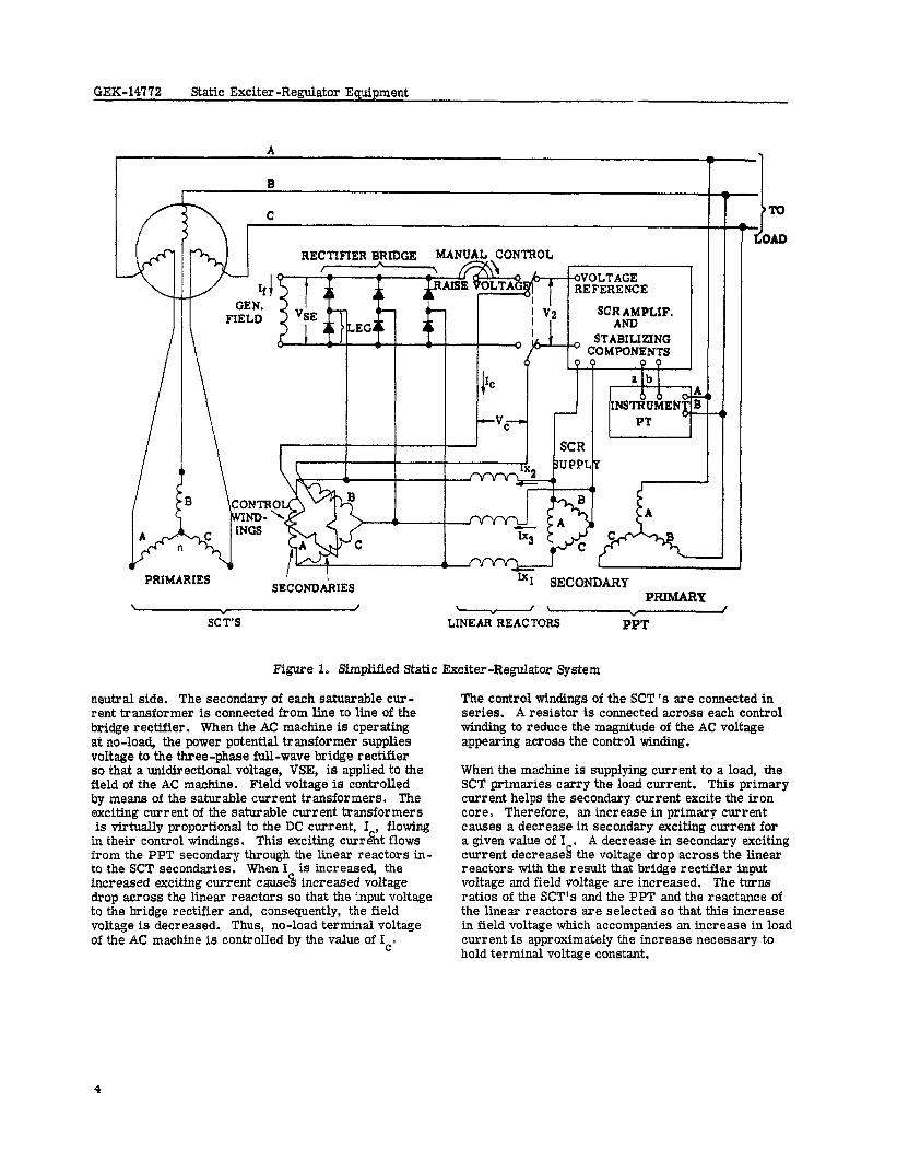
The power potential transformer (PPT) has its pri- mary windings -e-connected to the AC machine terminals. The secondary of the power potential transformer is connected to the power rectifier sec- tion through linear reactors as illustrated in Figure 1. Each saturable current transformer (SCT) pri- mary is located in a line of the AC machine on the
*Registered trademark of General Electric Company, U. S. A.
GEK-14772 Static Exciter -Regulator Equipment
oVOLTAGE REFERENCE
SCR AMPLIF. AND
STABILIZING ’ COMPONENTS
P? P Q
SECONDARIES PRIMARP
” / \ I i * / SC T’S LINEAR REACTORS PPT
Figure 1. Simplified Static Exciter-Regulator System
neutral side. The secondary of each satuarable cur- rent transformer is connected from line to line of the bridge rectifier . When the AC machine is oper sting at no-load, the power potential transformer supplies voltage to the three-phase full-wave bridge rectifier so that a unidirectional voltage, VSE, is applied to the field of the AC machine. Field voltage is controlled by means of the saturable current trausformers. The exciting current of the saturable current transformers is virtually proportional to the DC current, I , flowing
in their control windings. This exciting curr&t flows from the PPT secondary through the linear reactors in- to the SCT secondaries. When I is increased, the increased exciting current cause% increased voltage drop across the linear reactors so that the input voltage to the bridge rectifier and, consequently, the field voltage is decreased. Thus, no-load terminal voltage of the AC machine is controlled by the value of Ice
The control windings of the SCT ‘s are connected in series. A resistor is connected across each control winding to reduce the magnitude of the AC voltage appearing across the control winding.
When the machine is supplying current to a load, the SCT primaries carry the load current. This primary current helps the secondary current excite the iron core. Therefore, an increase in primary current causes a decrease in secondary exciting current for a given value of I . A decrease in secondary exciting current decreased the voltage drop across the linear reactors with the result that bridge rectifier input voltage and field voltage are increased. The turns ratios of the SCT’s and the PPT end the reactance of the linear reactors are selected so that this increase in field voltage which accompanies an increase in load current is approximately the increase necessary to hold terminal voltage constant.
Static Exciter -Regula or Equipment GEK-14772
It is an object of the design to maintain required ter- mmal voltage on the machine without requiring a change in control current Ic.
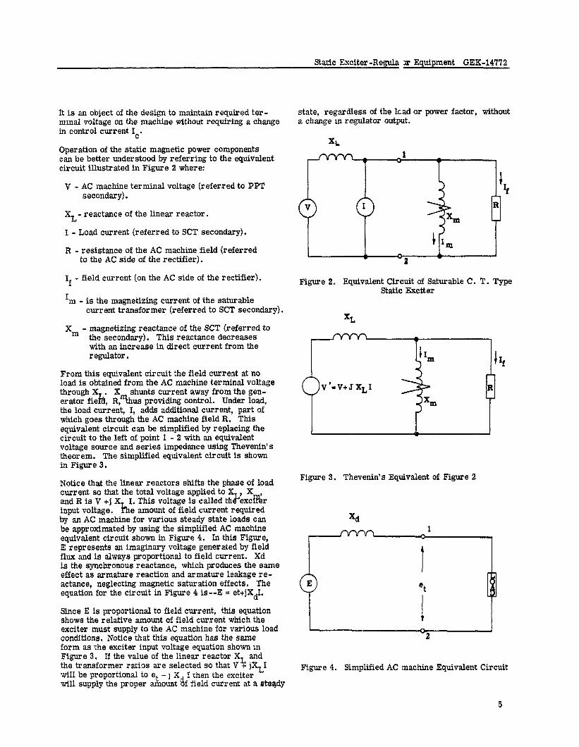
Operation of the static magnetic power components can be better understood by referring to the equivalent circuit illustrated in Figure 2 where:
V - AC machine terminal voltage (referred to PPT secondary).
XL- reactance of the linear reactor.
I - Load current (referred to SCT secondary).
R - resistance of the AC machine field (referred to the AC side of the rectifier).
If - field current (on the AC side of the rectifier).
I m - is the magnetizing current of the saturable current transformer (referred to SCT secondary).
xm - magnetizing reactance of the SCT (referred to the secondary). This reactance decreases with an increase in direct current from the regulator.
From this equivalent circuit the field current at no load is obtained from the AC machine terminal voltage
X shunts current away from the gen- t%?&i; R% us providing control. Under load, the load curreit, I, adds additional current, part of which goes through the AC machine field R. This equivalent circuit can be simplified by replacing the circuit to the left of point 1 - 2 with an equivalent voltage source and series impedance using Thevenin’s theorem. The simplified equivalent circuit is shown in Figure 3 0
Notice that the linear reactors shifts the phase of load current so that the total voltage applied to X X and R is V +j X I. This voltage is called th&xc& input voltage. h e amount of field current required by an AC machine for various steady state loads can be approximated by using the simplified AC machine equivalent circuit shown in Figure 4. In this Figure, E represents an imaginary voltage generated by field flux and is always proportional to field current. Xd is the synchronous reactance, which produces the same effect as armature reaction and armature leakage re- actance, neglecting magnetic saturation effects. The equation for the circuit in Figure 4 is--E = et+jXdI.
Since E is proportional to field current, this equation shows the relative amount of field current which the exciter must supply to the AC machine for various load conditions. Notice that this equation has the same form as the exciter input voltage equation shown m Figure 3. If the value of the linear reactor XL and the transformer ratios are selected so that V + jXL1 wifl be proportional to et + j X I then the exciter will supply the proper amount df field current at a steady
state, regardless of the lead or power factor, without a change III regulator output.
Figure 2. Equivalent Circuit of Saturable C. T. Type Static Exciter
Figure 3. Thevenin’s Equivalent of Figure 2
xd
Figure 4. Simplified AC machine Equivalent Circuit
5
GEK-14772 Static Exciter -Regulator Equipment
Due to various factors, such as AC machine field heating and field saturation, and other minor effects, it is necessary to trim this action of the PPT and SCT’s to provide the exact compensation for load changes. This is accomplished by the automatic regulator or by manually controlling the current in the saturating windings by means of the manualregulator voltage adjuster.
The suppression windings of the SCT’s are connected in series with a resistor across each winding. This resistor, like the control winding resistor, reduces the magnitude of the AC voltage appearing across the suppression winding.
When relay 415 is de-energized its power contact closes, applying power (usually 125 volts DC obtained from the station battery) to the suppression windings. The sequence of events that follows is the same as that produced by the maximum current flowing through the control windings, i.e., the exciting current in- creases causing and increased voltage drop across the linear reactors, therefore reducing the input vol- tage to the bridge rectifier and consequently the field voltage essentially to zero.
The three-phase bridge rectifier contains twelve cast aluminum finned heat sinks with two diodes mounted on each heat sink (one diode is the reverse polarity type, i.e., the stud is the anode). The bridge is convection air cooled. To insure adequate current carrying capability, two parallel rectifier bridges are furnished. No provisions for isolating one of the bridges have been made.
Each rectifier “leg” consists of two diodes in series to provide sufficient margin for the peak inverse vol- tages which may appear. The potted block assembly (PBA) connected across each diode will cause equal division of the peak inverse voltages which may occur due to power line transients.
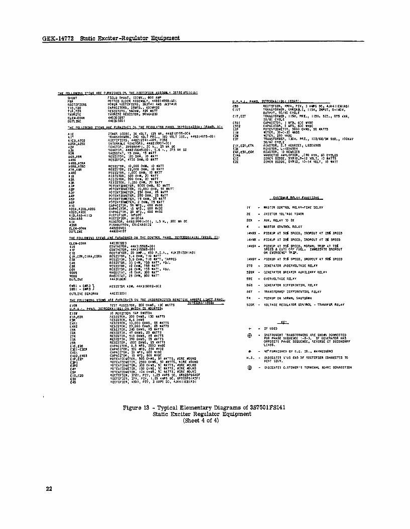
The Thyrite resistor, shown in Figure 13, connected across the rectifier bridge, protects the diodes from high peak inverse voltages which may occur as a re- sult of abnormal AC machine operation.
SILICON DIODE FUNDAMENTALS
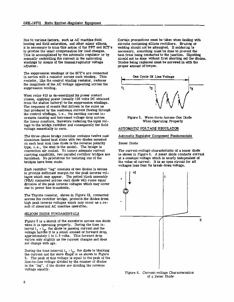
Figure 5 is a sketch of the waveform across one diode when it is operating properly. During the time in- terval tl - t , the diode is passing current and the voltage acre s it is a small amount of forward drop, % . approximately 1 to 1.5 volts. This forward drop varies only slightly as the current changes and does not change with age.
5. The peak of this voltage is equal to the peak of the line-to-line voltage divided by the number of diodes in the “leg”, If the diodes are dividing the reverse voltage equally.
Certain precautions must be taken when dealing with circuits containing silicon rectifiers. Brazing or welding should not be attempted. If soldering is necessary, something must be done to prevent the heat from being conducted to the junction. Hipotting should not be done without first shorting out the diodes, Diodes being replaced must be screwed in with the proper amount of torque.
I One Cycle Of Line Voltage I
Figure 5. Wave-form Across One Diode When Oper sting Properly
AUTOMATIC VOLTAGE REGULATOR
Automatic Regulator Component Fundamentals
Zener Diode
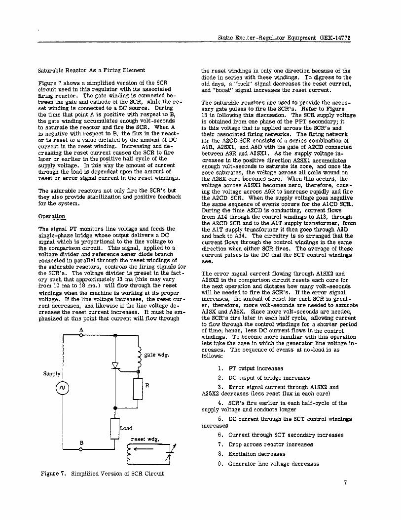
The current-voltage characteristic of a zener diode is shown in Figure 6. A zener diode conducts current at a constant voltage which is nearly independent of the value of current. It is an open circuit for all voltages less than its break-down voltage.
Figure 6. Current-voltage Characteristics of a Zener Diode
6
Static Exe .ter -Regulator Equipment GE&14772
Saturable Reactor As a Firing Element
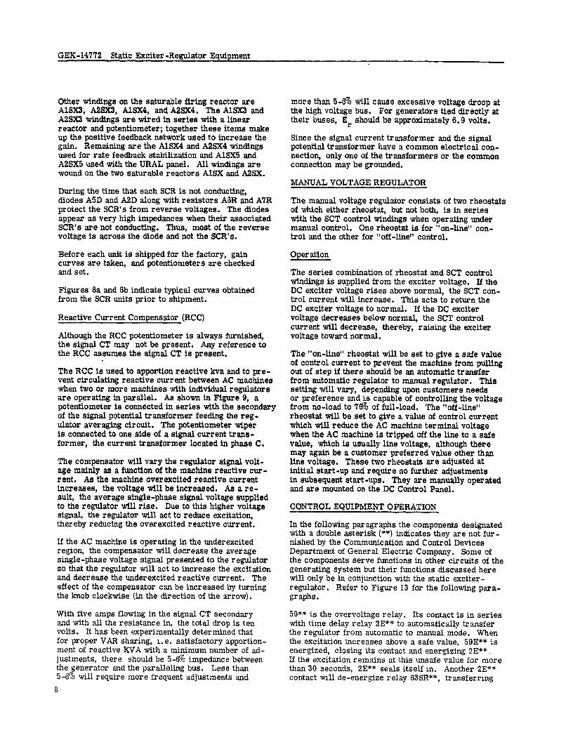
Figure 7 shows a simplified version of the SCR circuit used in this regulator with its associated firing reactor. The gate winding is connected be- tween the sate and cathode of the SCR. while the re- set wind& is connected to a DC source. During the time that point A is positive with respect to B, the gate winding accumulates enough volt-seconds to saturate the reactor and fire the SCR. When A is negative with respect to B. the flux in the react- or is reset to a value dictated by the amount of DC current in the reset winding. Increasing and de- creasing the reset current causes the SCR to fire Iater or earlier in the positive half cycle of the supply voltage. In this way the amount of current through the load is dependent upon the amount of reset or error signal current in the reset windings.
The saturable reactors not only fire the SCR’s but they also provide stabilization and positive feedback for the system.
Operation
The signal PT monitors line voltage and feeds the single-phase bridge whose output delivers a DC signal which is proportional to the line voltage to the comparison circuit. This signal, applied to a voltage divider and reference zener diode branch connected in parallel through the reset windings of the saturable reactors, controls the firing signals for the SCR’s. The voltage divider is preset in the fact- ory such that approximately 13 ma (this may vary from 10 ma to 18 ma.) will flow through the reset windings when the machine is working at its proper voltage. If the line voltage increases, the reset cur- rent decreases, and likewise if the line voltage de- creases the reset current increases. It must be em- phasized at this point that current will flow through
gate wdg. N c: 2 R
the reset windings in only one direction because of the diode in series with these windings. To digress to the old days, a “buck” signal decreases the reset current, and “boost” signal increases the reset current.
The saturable reactors are used to provide the neces- sary gate pulses to fire the SCR’s. Refer to Figure 13 in following this discussion. The SCR supply voltage is obtained from one phase of the PPT secondary; it is this voltage that is applied across the SCR’s and their associated firing networks. The firing network for the ABCD SCR consists of a series combination of A5R, A2SX1, and A6D with the gate of A2CD connected between A9R and A2SXl. As the supply voltage in- creases in the positive direction APSXl accumulates enough volt-seconds to saturate its core, and once the core saturates, the voltage across all coils wound on the A2SX core becomes zero. When this occurs, the voltage across A2SXI becomes zero, therefore, caus- ing the voltage across A9R to increase rapidly and fire the ASCD SCR. When the supply voltage goes negative the same sequence of events occurs for the AlCD SCR. During the time A2CD is conducting, current flows from A14 through the control windings to AU, through the A2CD SCR and to the AlT supply transformer, from the AlT supply transformer it then goes through A2D and back to A14. The circuitry is so arranged that the current flows through the control windings in the same direction when either SCR fires. The average of these current pulses is the DC that the SCT control windings see.
The error signal current flowing through AlSX2 and A2SX2 in the comparison circuit resets each core for the next operation and dictates how many volt-seconds will be needed to fire the SCR’s. If the error signal increases, the amount of reset for each SCR is great- er, therefore, more volt-seconds are needed to saturate AlSX and A2SX. Since more volt-seconds are needed, the SCR’s fire later in each half cycle, allowing current to flow through the control windings for a shorter period of time; hence, less DC current flows inthe control windings. To become more familiar with this operation lets take the case in which the generator line voltage in- creases. The sequence of events at no-load is as follows:
1. PT output increases 2. DC output of bridge increases 3. Error signal current through AlSX2 and
A25X2 decreases (less reset flux in each core) 4. SCR’s fire earlier in each half-cycle of the
supply voltage and conducts longer 5. DC current through the SCT control windings
increases 6. Current through SCT secondary increases 7. Drop across reactor increases 8. Excitation decreases
9. Generator line voltage decreases
Figure 7. Simplified Version of SCR Circuit
GEK-14’772 Static Exciter -Regulator Equipment
Other windings on the saturable firing reactor are AlSX3, A2SX3, AlSX4, and A2SX4. The AlSX3 and A2SX3 windings are wired in series with a linear reactor and potentiometer; together these items make up the positive feedback network used to increase the gain. Remaining are the AlSE4 and A2SX4 windings used for rate feedback stabilization end AlSX5 and A2SX5 used with the URAL panel. All windings are wound on the two saturable reactors AlS2S and A2SX.
During the time that each SCR is not conducting, diodes A5D and A2D along with resistors A8R and A7R protect the SCR’s from reverse voltages. The diodes appear as very high impedances when their associated SCR’s are not conducting, Thus, most of the reverse voltage is across the diode and not the SCR’s.
Before each unit is shipped for the factory, gain curves are taken, and potentiometers are checked and set.
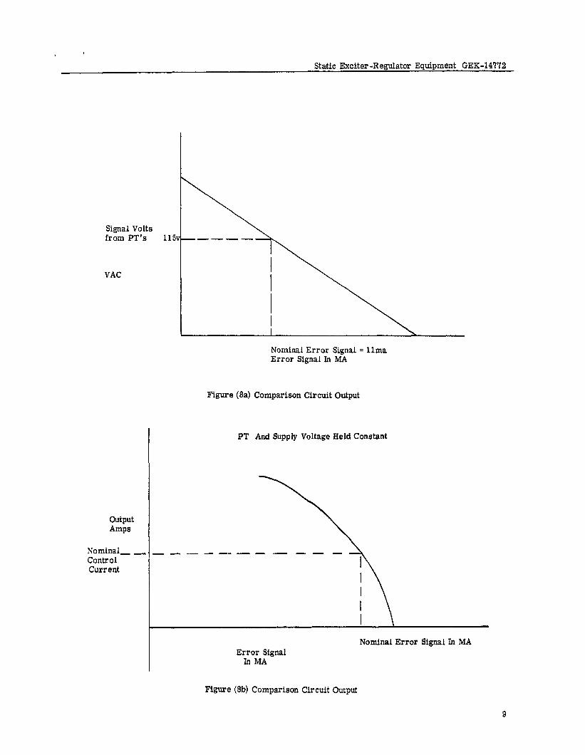
Figures 8a and 8b indicate typical curves obtained from the SCR units prior to smpment.
Reactive Current Compensator (RCC)
Although the RCC potentiometer is always furnished, the signal CT may not be present. Any reference to the RCC assumes the signal CT is present.
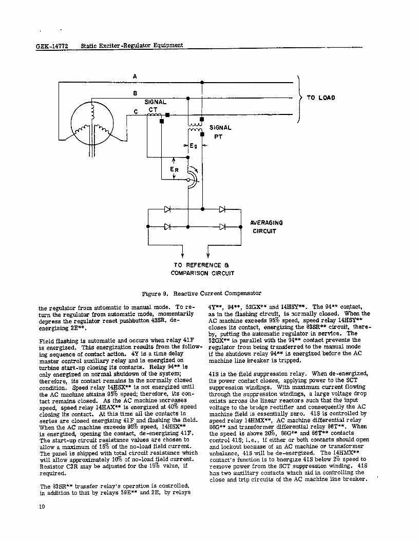
The RCC is used to apportion reactive kva and to pre- vent circulating reactive current between AC machines when two or more machines with individual regulators are operating in parallel. As shown in Figure 9, a potentiometer is connected in series with the secondary of the signal potential transformer feeding the reg- ulator averaging circuit. The potentiometer wiper is connected to one side of a signal current trans- former, the current transformer located in phase C.
The compensator will vary the regulator signal volt- age mainly as a function of the machine reactive cur- rent. As the machine overexcited reactive current increases, the voltage will be increased. As a re- sult, the average single-phase signal voltage supplied to the regulator will rise. Due to this higher voltage signal, the regulator will act to reduce excitation, thereby reducing the overexcited reactive current,
If the AC machine is operating in the underexcited region, the compensator will decrease the average single-phase voltage signal presented to the regulator so that the regulator will act to increase the excitation and decrease the underexcited reactive current. The effect of the compensator can be increased by turning the knob clockwise (in the direction of the arrow).
With five amps flowing in the signal CT secondary and with all the resistance in, the total drop is ten volts. It has been experimentally determined that for proper VAR sharing, i.e. satisfactory apportion- ment of reactive EVA with a minimum number of ad- justments, there should be 5-60/o impedance between the generator and the paralleling bus. Less than 5-a will require more frequent adjustments and
8
more thsn 5-e will cause excessive voltage droop at the high voltage bus. For generators tied directly at their buses, Er should be approximately 6.9 volts.
Since the signal current transformer and the signal potential transformer have a common electrical con- nection, only one of the transformers or the common connection may be grounded.
MANUALVOLTAGEREGULATOR
The manual voltage regulator consists of two rheostats of which either rheostat, but not both, is in series with the SCT control windings when operating under manual control. One rheostat is for “on-line” con- trol and the other for “off-line” control.
Operation
The series combination of rheostat and SCT control windings is supplied from the exciter voltage. If the DC exciter voltage rises above normal, the SCT con- trol current will increase. This acts to return the DC exciter voltage to normal. If the DC exciter voltage decreases below normal, the SCT control current will decrease, thereby, raising the exciter voltage toward normal.
The “on-line” rheostat will be set to give a safe value of control current to prevent the machine from pulling out of step if there should be an automatic transfer from automatic regulator to manual regulator. This setting will vary, depending upon customers needs or preference and is capable of controlling the voltage from no-load to ‘I& of full-load. The “off -line” rheostat will be set to give a value of control current which will reduce the AC machine terminal voltage when the AC machine is tripped off the line to a safe value, which is usually line voltage, although there may again be a customer preferred value other than line voltage. These two rheostats are adjusted at initial start-up and require no further adjustments in subsequent start-ups. They are manually operated and are mounted on the DC Control Panel.
CONTROL EQUIPMENT OPERATION
In the following paragraphs the components designated with a double asterisk (**) indicates they are not fur- nished by the Communication and Control Devices Department of General Electric Company. Some of the components serve functions in other circuits of the generating system but their functions discussed here will only be in conjunction with the static exciter- regulator. Refer to Figure 13 for the following para- graphs .
59** is the overvoltage relay. Its contact is in series with time delay relay 2E** to automatically transfer the regulator from automatic to manual mode. When the excitation increases above a safe value, 59E** is energized, closing its contact and energizing 2E**. If the excitation remains at this unsafe value for more than 30 seconds, 2E** seals itself m. Another 2E** contact ~11 de-energize relay 83SR**, transferring
Static Exciter-Regulator Equipment GEK-14772
Signal Volts from PT’s 115
VAC
Nominal Error Signal = lima Error Signal In MA
Figure (Sal Comparison Circuit Output
PT And Supply Voltage Held Constant
Output Amps
Nominal _ _ - - - .-- - - - Control Current
Error Signal In MA
Nominal Error Signal In WA
Figure G-34 Comparison Circuit Output
9
GEK-14772 Static Exciter -Regulator Equipment
8 SIGNAL -
c CT
1 SIGNAL
---% PT ‘Eo *
+ ”
w.1 N
0 N N AVERAGING IA CIRCUIT
I 1 TO REFERENCE a
COMPARlSON CIRCUIT
Figure 9. Reactive Current Compensator
1 TO LOAO
the regulator from automatic to manual mode. To re- turn the regulator from automatic mode, momentarily depress the regulator reset pushbutton 43% de- energizing 2E**.
Field flashing is automatic and occurs when relay 41F is energized, This energization results from the follow- ing sequence of contact action. 4Y is a time delay master control auxiliary relay and is energized on turbine start-up closing its contacts. Relay 94** is only energized on normal shutdown of the system; therefore, its contact remains in the normally closed condition. Speed relay 14HSX** is not energized until the AC machlne attains 95% speed; therefore, its con- tact remains closed. As the AC machine mcresses speed, speed relay 14HAX** is energized at 49% speed closing its contact. At this time all the contacts in series are closed energizing 41F and flashing the field. When the AC machine exceeds 95% speed, 14HSX** is energized, opening the contact, de-energizing 4lF. The start-up circuit resistance values are chosen to allow a maximum of 15% of the no-load field current. The panel is shipped with total circuit resistance which will allow approximately 10% of no-load field current. Resistor C3R may be adjusted for the 15% value, if required.
The 83SR** transfer relay’s operation is controlled, in addition to that by relays 59E** and 2E, by relays
10
4Y**, 94**, 52GX?* and 14HSY**. The 94** contact, as in the flashing circuit, is normally closed. When the AC machine exceeds 95% speed, speed relay 14HsT** closes its contact, energizing the 83SR** circuit, there- by, putting the automatic regulator in service. The 52GX** in parallel with the 94** contact prevents the regulator from being transferred to the manual mode if the shutdown relay 94** is energized before the AC machine line breaker is tripped.
41s is the field suppression relay. When de-energized, its power contact closes, applying power to the SCT suppression windings. With maximum current flowing through the suppression windings, a large voltage drop exists across the linear reactors such that the input voltage to the bridge rectifier and consequently the AC machine field is essentially zero. 41s is controlled by speed relay 14HMX**, AC machine differential relay 86G** end transformer differential relay 86T**. When the speed is above 29%, 86G** and 86T** contacts control 41s; i.e., if either or both contacts should open end lockout because of an AC machine or transformer unbalance, 41s will be de-energized. The 14HMX** contact’s function is to Bnerglze 41s below 2% speed to remove power from the SCT suppression winding. 41s has two auxiliary contacts whxh aid in controlling the close and trip circuits of the AC machine line breaker. ’
Static Exciter -Regulator Equipment GEK-14772
CT AND PT BURDENS
The regulator imposes a maximum burden of 50 volt- amperes on the signal current transformer and 25 volt-amperes on the signal potential transformer 0 The URAL (when furnished) imposes a maximum burden of 300 volt-amperes on the signal PT and 250 volt-amperes on the signal CT.
INSTALLATION
LOCATION AND MOUNTING
The rectifier-reactor assembly, resistor assemblies PPT, and the SCT’s are mounted in the AC machine cab. They are convection cooled. All components are floor mounted.
CONNECTIONS
Connections must be made in accordance with the diagrams supplied with the equipment for each partic- ular installation. Care must be exercised to deter- mine that the connections are correct to avoid dam- aging the equipment.
The size of the interconnecting wires for the regulator and control panels and the rectifier -reactor assembly (also the field breaker control circuit when applic- able) is to be a minimum of #I4 wire. The minimum size of the interconnecting cables for the rectifier- reactor assembly will vary with the rating of the equip- ment and is shown on the rectifier-reactor assembly outline.
Care should be taken that the DC supply is connected with the polarity shown. If reversed, the start-up circuit blocking rectifier will prevent the start-up current from flowing in the field circuit.
Instrument transformers, both current and potential, should be connected as shown in the diagram. The current transformer should be brought to the regulator through a shorting device.
POLARITY AND PHASE ROTATION
When making connections to the static exciter-regu- lator, polarity should be carefully checked to make certain that the connections are the same as those shown on the elementary.
It is extremely important that the PPT and SCT’s are connected with the polarity-marked ends as shown on the elementary. Failure to do so can cause damage to the eo&pment or improper operation of the circuit.
INITIAL OPERATION, TEST AND ADJUSTMENT
CONTROL CIRCUITS
The following relays can be checked before operating the AC machine. Upon application of the DC supply voltage, relay 41s should immediately pick-up. Placing a jumper across speed relay contact 14HSY** will energize the transfer relay 83SR**.
Short 59E contact energizing 2E. Nothing else should occur for 30 seconds after which a 2E** contact will close and seal itself in (the 59E** contact can now be released). Another ZE** contact will de-energize re- lay 83SR**. Depressing 43SR** will return the relays to their former condition. Remove the 14HsrC* jump- er and place it across speed relay contact 14HAX**. 41F relay should pick up.
STATIC EXCITER
Since the automatic regulator is automatically switched into service immediately following start-up, the 83SR** circuit must be disabled to prevent this so that the “off-line” (90R5) and “on-line” (90R6) manual regulator rheostats can be adjusted. The means used to accom- plish this is optional but should allow for easy con- necting and disconnecting for future tests. .
As the AC machine begins rotating and the start-up circuit is switched into operation, the exciter -volt - age and AC machine voltage should build up to a small percentage of rated voltage. If the voltage shows no signs of building up, shutdown the equipment, turn the “off -line” voltage adjuster rheostat 9OR5 clockwise, to add some resistance and try again. It should be re- membered that the field circuit is highly inductive, and the build-up will be slow. Therefore, it is im- perative that all adjustments be made in small incre- ments until the operator becomes familiar with the characteristics of the particular machine. Adding too much resistance may cause the AC machine to build up to too high a value. The final setting should be noted for future start-ups.
Once the voltage has started to build up, it shouId be possible to control it with 90R5. With the AC machine operating at normal voltage, turn 90R5 clockwise. This will increase the resistance in series with the saturating winding and cause an increase in exciter voltage and AC machine voltage. Turning 90R5 counter- clockwise will have the opposite effect. The change in exciter voltage and .4C machine voltage should be smooth and easy to control.
C6R may be adjusted so there is sufficient range of voltage control on 90R5. The adjustment of the on- line manual regulator circuit depends upon the AC machine characteristics and customer requirements and may involve trial and error.
11
GEK-14772 Static Exciter -Regulator Equipment
When finally adjusted, the values of C4R and C5R will be such that maximum desired AC machine output will occur with 90R6 at its maximum resistance position.
To accomplish this, we must start with the total re- sistance of the on-line circuit equal to the total re- sistance of the off-line circuit when 9OR5 is in its proper start-up position.
With some active load on the AC machine, adjust 90R6 until the AC machine is carrying the desired reactive load.
If this is impossible to attain, shut down the equip- ment and increase the effective resistance of C4R and C5R. Too much resistance will make it impos- sible to operate as low as might be desired.
Voltage Level
The automatic regulator is designed and transformer ratios are selected to give a nominal signal voltage of approximately 115 volts to the single-phase bridge consisting of diodes A7D through AlOD. 90Rl (“off - line”) end 90R2 (“on-line”) should provide adjustment of at least 10% above and below nominal signal volt- age. It is usually preferable to delay the final voltage level adjustment until the reactive current compen- sator is adjusted, as it may appreciably alter the signal voltage.
Automatic Control
The reactive current compensator (A6P) control knob should be turned fully counterclockwise (minimum affect). The URAL amplifier should be removed from service by disconnecting the wire from terminal E8, Figure 13.
With the AC machine operating at rated voltage, rated speed, and disconnected from the line, and with 9OR4 (90Rl if Manual adjust used) in its midposition, take whatever steps are necessary to energize 83SR**, thereby causing the AC machine to be under the con- trol of the automatic regulator. Watch carefully for signs of instability since the system will be most un- stable under these conditions. If the system is un- stable, immediately de-energize 83SR**.
Attempt to obtain stable operation by adjusting rhe- ostat A2P in series with capacitor AX (A2C actually consists of five separate capacitors A2CA-A2CE. Refer to the regulator panel connection diagram). Re- duce the resistance to a value that is about 1% less than the original value and again place the regulator in control of the AC machine excitation. If the stability still has not improved, repeat the preceding adjustment using larger and smaller values of resistance. It should be possible to stabilize the regulator by gradual adjustment of this rheostat. However, if the regulator 1s still unstable after the full range of resistance has been tried, the exciter stabilizer capacitors (AZCA- h2CE) should be adjusted in the same manner as pre- vlouslg described.
When proper regulator operation has been secured, optimum stability should be checked by the following test and the necessary additional adjustments made, With the regulator in control of the AC machine, ad- just 9OR4 (9ORl if Manual adjust used) to hold AC machine volts at approximately 9% or greater. De- energize 83SR**, putting manual regulator back in control of the AC machine. When the AC machine is back at rated voltage and steady, energize 83SR**. The AC machinevoltmeter should overshoot only slightly before returning to the new steady state value.
Before making any adjustments in the stabilizer circuit, it is necessary to transfer to manual control when adjusting A2P or to shut down the unit to adjust A2C.
The on line auto-regulator should be set to cause the generator to go on line at a voltage higher than line voltage in order to supply reactive power to the sys- tem. With the motor operated set point adjuster, this is accomplished by setting 9ORl to some small value to give a step change in voltage. With the man- ual set point adjuster, 9ORl should be set to hold rated line voltage and 9OR2 to hold a voltage slightly higher than rated.
If the signal PT voltage is other than 115 volts, it will be necessary to adjust rheostat A3P and/or A4P to bring the regulator back to a good operating range. Failure to do this may result in the voltage adjuster not having enough range.
When smooth control and the desired operation has been obtained, the reactive current compensator po- tentiometer A6P can now be adjusted (turning clock- wise) for the desired compensation for reactive cur- rent. Refer to the reactive current compensator cir- cuit description under the section titled “Automatic Voltage Regulator” as a guide for the setting of A6P for optimum performance.
Final adjustment of the compensator can only be made after consider able experience with the machine oper - ating under control of the automatic regulator. It is desirable to keep the amount of resistance used to the minimum required for proper division of reactive kva between machines to avoid excessive voltage regulation. Adjustments may be made with the compensator cur- rent transformer energized. When making adjust- ments, the AC machine power factor should swing toward unity as A6P resistance is increased.
Regulator Sensitivity and Voltage Regulation
Determination of AC machine voltage regulation witi. the regulator in sermce is a difficult procedure under usual operating conditions and one which will produce only qualitative results. Since the regulator is ad- justed at the factory to provide adequate sensitivity
Static Exciter -Regulator Equipment GEK-147’72
for close regulation, this measurement is usually unnecessary at the time of installation, and for this reason no special test procedure is given, After the equipment has been placed in service, it is possible to obtain data which will provide a measure of volt- age regulation, but results must be carefully inter- preted to gain a reliable estimate of performance.
If the machine is connected to a system, the regula- tion will depend to a great extent upon the character- istics of this system. Regulation will also be con- siderably affected by the use and adjustment of com- pensators. Furthermore, the sensitivity of the reg- ulator itself will be a malor factor affecting voltage regulation.
GAIN MEASUREMENTS
The automatic regulator gain should be checked only when it is thought that the system is not operating properly. If the gain is to be checked, it will be nec- essary to use a laboratory type meter to measure the change in voltage on the secondary of the PT; the ratio of change in voltage across points Al4 and Al3 (See Figure 13) to the voltage change at the P’l! sec- ondary is the gain of the SCR circuit. The voltage across Al4 and A13 is the output of the SCR circuit.
SYSTEM SELF-COMPENSATION
It is necessary to determine the degree of self-compen- sation of this system to be certain that the linear reac- tors are set at the best taps. This can be done by meas- uring the value of current through the SCT control wind- ing at no-load and at full load, rated power factor. The degree-of-correction (DOC) is the change in control cur- rent divided by the no-load value of control current. If the control current decreases from no-load to full load the system is under-compounded. If the current in- creases, the system is over -compounded. Changing the linear reactors to a higher reactance tap causes in- creased compensation, i. e., it tends to over-compound the system. CHANGE TAPS ON ALL THREE RE- ACTORS.
UNDEREXCITED REACTIVE AMPERE LIMIT (If Furmshed)
Limit Polarity
After satisfactory operation of the regulator has been obtained, the reactive-ampere limit should be tested. Reconnect the limit amplifier to the regulator, set the REACTIVE AMPERE LIMIT POWER RECALIBRA- TION switch at zero and the REACTIVE AMPERE LIMIT START dial at its highest numbered position.
83SR** should be disabled so that the regulator re- mains in Manual. Connect the test resistor furnished loose with the URAL panel to terminals Al3 and Al4 of the automatic regulator. This resistor 1s necessary in order for the regulator to supply enough current for the SCR’s to conduct properly. Connect a voltmeter across Al3 and Al4 and adjust the automatic regulator output for about 60 volts.
With the machine carrying power load and some safe value of underexcited reactive current, slowly turn the REACTIVE AMPERE LIMIT START dial toward 0. At same setting of the dial, the limit detector meter read- ing will go to 0 and increase in the opposite direction. Limit signal-current will increase from 0 and the reg- ulator output will decrease. If the limit-detector current does not reverse before the dial has been turned to zero, return the dial to the highest numbered po- sition. Decrease the AC machine excitation to further increase the underexcited current being careful not to exceed the safe operating limit for the machine.
Again turn the REACTIVE AMPERE LIMIT START dial towards zero until the limit detector current is 10 ma. If the signal cannot be increased from zero by turning the REACTIVE AMPERE LIMIT START dial to zero, the limit polarity may be reversed. Reverse the primary connections of transformer E3T (Figure 13). Repeat the test previously described to determine if reverse limit-detector current can be obtained by turning the REACTIVE AMPERE LIMIT START dial towards zero. THIS TEST MUST GIVE PROPER RE- SULTS BEFORE FURTHER TESTS ARE CONDUCTED. If the limit signal-current had en initial value that went to zero as the REACTIVE AMPERE LIMIT START dial setting was reduced, the input to the limit amplifier must be reversed. If the regulator output increased, the limit DC output is reversed. Reverse the con- nections between the limit amplifier and the first stage amplifier of the automatic regulator. Repeat the pre- viously described tests to obtain proper results.
With the REACTIVE AMPERE LIMIT START dial so set that the regulator output has been reduced slightly, turn the POWER RECALIBRATION switch from point 0 toward point 9. If the AC machine is delivering power, regulator output should decrease as the POWER RE- CALIBRATION switch is turned toward point 9.
Turn the POWER RECALIBRATION switch to 0. Re- adjust the regulator output to 60 volts with the RE- ACTIVE AMPERE LIMIT START dial. Before pro- ceeding further with the test on the underexcited re- active limit circuit, it is necessary to check the po- larity of the LIMIT stabilizing circuit. Carefully dis- connect one of the exciter voltage stabilizing leads from the LIMIT amplifier and short the stabilizing input terminals on the LIMIT amplifier. This should cause the regulator output to decrease. Replacing the pri- mary lead should cause the regulator output to increase. Do not proceed with the underexcrted reactive-ampere limit tests until the polarity of the limit stabilizer is correct.
Turn the REACTIVE AMPERE LIMIT START dial to its highest reading. Readjust the regulator output to 60 volts with 90R4 (or 90R2). Operate the AC machine at normal voltage and with underexcited reactive cur- rent. Remove the test resistor and then energize 83SR** so that the regulator transfers to automatic. With 90R4 (or 90R2) readjust the output for the same normal voltage and underexcited current. Slowly turn the REACTIVE AMPERE LIMIT START dial toward zero. The regulator output should decrease end the
13
GEX-14772 Static Exciter -Regulator Equipment
exciter voltage should increase causing the under- excited reactive current to decrease. The dial setting at which the uuderexcited reactive current starts to decrease is the limit-start point. If the operation is not as described, immediately remove the regulator from control of the AC machine excitation by dis- abling 83SR**. Repeat the limit polarity tests. Do not proceed further until satisfactory operation is obtained.
With 83SR** energized, the test resistor disconnected, and the REACTIVE AMPERE LIMIT START dial at the limit start point, observe the exciter voltmeter and the AC machine ammeter for signs of oscillation. If oscillations of the reactive current appear, remove the automatic-regulator from control of the machine excitation. Adjust the resistance in series with the exciter LIMIT stabilizing capacitors in 15 percent steps, first in the direction to decrease resistance and then in the direction to increase resistance. After each of these adjustments repeat the procedure for putting the LIMIT in service as previously described, being very careful to observe exciter voltage oscillation and reactive-current oscillations. However, if the LIMIT still is unstable after the full range of re- sistance has been tried, the exciter stabilizer cap- acitors on the LIMIT amplifier should be added and disconnected one at a time, After each change the resistance should be adjusted in the same manner as previously described. Capacitors should be changed only when the machine has no voltage on it.
NOTE
TEST RESISTOR MUST BE DISCON- NECTEDBEFOREOPERATINGTHE THE REGULATOR IN AUTO.
After stable operation of the LIMIT has been obtained, check the LIMIT operation as follows with the re- gulator in control of AC machine excitation. Move the REACTIVE AMPERE LIMIT START dial to the limit-start point. Record the reactive current. De- crease the underexcited reactive-ampere load on the AC machine by operating the automatic-regulator voltage adjuster to raise the voltage. The under- excited reactive current should decrease. It should be possible to adjust the underexcited reactive cur- rent to any value lower than it was at the limit-start point. Now increase the underexcited reactive cur- rent by turning the automatic -regulator voltage ad- juster to lower the voltage, As the limit-start point is passed, the exciter voltage should increase and it
should be impossible to raise the underexcited re- active current appreciably above the previously re- corded value no matter how far the automatic-regula- tor voltage adjuster is turned in the direction to lower voltage.
This completes the preliminary adjustment of the LIMIT. Final adjustment can be made at any time.
Final Adjustment of The Underexcited Reactive-Am- pere Limit
The final adjustment of the LIMIT may be made by use of Figure 10 and 11, unless special calibration data are supplied with the equipment.
The limit-start adjustment is determined from Fig- ure 10. This graph shows the value of the machine current-transformer secondary underexcited reactive current which will cause the LIMIT to operate as a function of dial setting and normal AC machine po- tential-transformer secondary voltage. Values of voltages differing from those shown on the graph may be easily interpolated. The Power-Recalibrating Reactor adjustment is shown in Figure 11. This curve shows the amount by which the limit-start point will be reduced below the limit-start adjustment ae a function of machine current-transformer secondary active Current for various values of the tap-switch (EISW 9 etting . The two following examples are given to Illustrate the method of setting the LIMIT.
EXAMPLE 1. It is required that the LIMIT should start to function when the under excited reactive-cur - rent input to the LIMIT reaches four amperes and that the LIMIT action be independent of the power com- ponent of current. The normal voltage on the sec- ondary of the AC machine potential transformers is 110 volts.
Figure 10 indicates that for an underexcited reactive current of four amperes, the REACTIVE AMPERE LIMIT START dial should be set at approximately 47. As can be seen from Figure 11, the tap switch on the power-recalibrating reactor must be set on tap 0. since the LIMIT action is to be independent of the power component of current.
EXAMPLE 2. It is desired to have the LIMIT start to function when the underexcited reactive-current in- put to the LIMIT reaches four amperes with zero active amperes, and when the underexcited reactive- current input reaches three amperes with four active amperes.
14
Static Exciter -Regulator Equipment GEK-147’72
Figure 10.
SENSITIVITY RHEOSTAT (BIRH) II YLAN coslTloll
0 ID 20 30 40 so 60 70 60 LIMIT-STMT DIK SLttlNQ
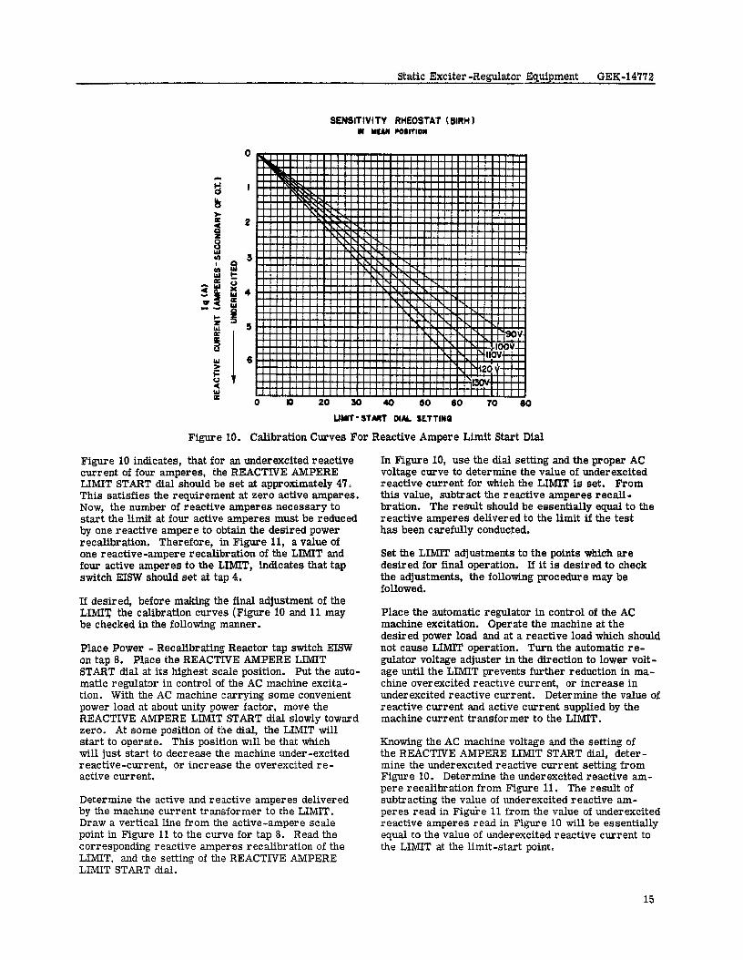
Calibration Curves For Reactive Ampere Limit Start Dial
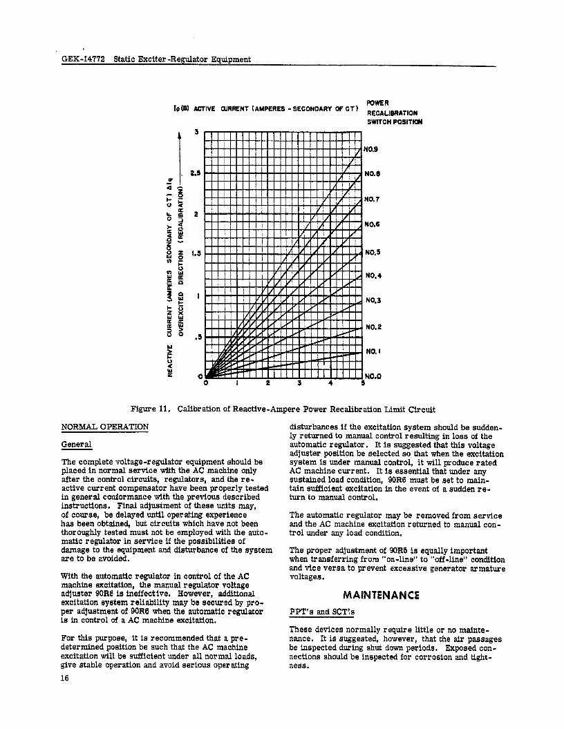
Figure 10 indicates, that for an underexcited reactive current of four amperes, the REACTIVE AMPERE LIMIT START dial should be set at approximately 47. This satisfies the requirement at zero active amperes. Now, the number of reactive amperes necessary to start the limit at four active amperes must be reduced by one reactive ampere to obtain the desired power recalibration. Therefore, in Figure 11, a value of one reactive -ampere recalibration of the LIMIT and four active amperes to the LIMIT, indicates that tap switch EISW should set at tap 4.
If desired, before making the final adjustment of the LIMIT the calibration curves (Figure 10 and 11 may be checked in the following manner.
Place Power - Recalibrating Reactor tap switch RISW on tap 8. Place the REACTIVE AMPERE LIMIT START dial at its highest scale position. Put the auto- matic regulator in control of the AC machine excita- tion. With the AC machine carrying some convenient power load at about unity power factor, move the REACTIVE AMPERE LIMIT START dial slowly toward zero. At some position of the dial, the LIMIT will start to operate. This position ~11 be that which will just start to decrease the machine under-excited reactive-current, or increase the overexcited re- active current.
Determine the active and reactive amperes delivered by the machme current transformer to the LIMIT. Draw a vertical line from the active-ampere scale point in Figure 11 to the curve for tap 8. Read the corresponding reactive amperes recalibration of the LIMIT. and the setting of the REACTIVE AMPERE LIMIT START dial.
In Figure 10, use the dial setting and the proper AC voltage curve to determine the value of underexcited reactive current for which the LIhlIT is set. From this value, subtract the reactive smperes recali- bration. The result should be essentially equal to the reactive amperes delivered to the limit if the test has been carefully conducted.
Set the LIMIT adjustments to the points which sre desired for final operation. If it is desired to check the adjustments, the following procedure may be followed.
Place the automatic regulator in control of the AC machine excitation. Operate the machine at the desired power load and at a reactive load which should not cause LIMIT operation. Turn the automatic re- gulator voltage adjuster in the direction to lower volt- age until the LIMIT prevents further reduction in ma- chine overexcited reactive current, or increase in under excited reactive current. Deter mine the value of reactive current and active current supplied by the machine current transformer to the LIMIT.
Knowing the AC machine voltage and the setting of the REACTIVE AMPERE LIMIT START dial, deter- mine the underexcited reactive current setting from Figure 10. Determine the underexcited reactive am- pere recalibration from Figure 11. The result of subtracting the value of underexcited reactive am- peres read in Figtie 11 from the value of underexcited reactive amperes read in Figure 10 will be essentially equal to the value of underexcited reactive current to the LIMIT at the limit-start point.
15
GEK-14772 Static Exciter -Regulator Equipment
rp (61 ACTIVE OJRRENT (AMPERES - SECONDARY OF Cl) POWER
SWITCH POSItlOW
NO.9
2.3 NO.6
NO.7
2 /! ! -V! I NO.6
I
t i i i i i i NO.3
NO.2
Figure 11. Calibration of Reactive-Ampere Power Recalibration Limit Circuit
NORMAL OPERATION
General
The complete voltage-regulator equipment should be placed in normal service with the AC machine only after the control circuits, regulators, and the re- active current compensator have been properly tested in general conformance with the previous described instructions. Final adjustment of these units may, of course, be delayed until operating experience has been obtained, but circuits which have not been thoroughly tested must not be employed with the auto- matic regulator in service if the possibilitiee of damage to the equipment and disturbance of the system are to be avoided.
With the automatic regulator in control of the AC machine excitation, the manual regulator voltage adjuster 90R6 is ineffective. However, additional excitation system reliability may be secured by pro- per adjustment of 90R6 when the automatic regulator is in control of a AC machine excitation.
For this purpose, it is recommended that a pre- determined position be such that the AC machine excitation will be sufficient under all normal loads, give stable operation and avoid serious operating 16
disturbances if the excitation system should be sudden- ly returned to manual control resulting in loss of the automatic regulator. It is suggested that this voltage adjuster position be selected so that when the excitation system is under manual control, it will produce rated AC machine current. It is essential that under any sustained load condition, 90R0 must be set to main- tain sufficient excitation in the event of a sudden re- turn to manual control.
The automatic regulator may be removed from service and the AC machine excitation returned to manual con- trol under any load condition.
The proper adjustment of 90R5 is equally important when transferring fro.m “on-line” to “off-line” condition and vice versa to prevent excessive generator armature voltages.
MAINTENANCE PPT’s end SCT!s
These devices normally require little or no mainte- nance. It is suggested, however, that the air passages be inspected during shut down periods. Exposed con- nections should be inspected for corrosion and tight- ness.
Static Exciter -Regulator E iuipment GEE-147’72
STATIC EQUIPMENT
If vibration is present, all screw type connections should be checked regularly. Normally, the static components should require no further attention.
OTHER EQUIPMENT
All contactors and relays should be regularly inspected and maintained in accordance with applicable instruc- tions. The automatic and manual regulator voltage ad- juster contact brushes should be inspected annually and the brushes should be reset by working them back and forth across the total winding surface many times. If arcing is present, or ff brush becomes worn, a com- plete brush assembly should be installed. Since it is made of special material, it should be obtained from the rheostat manufacturer. In addition, where dis- coloration is present, clean the contact surface with crocus cloth.
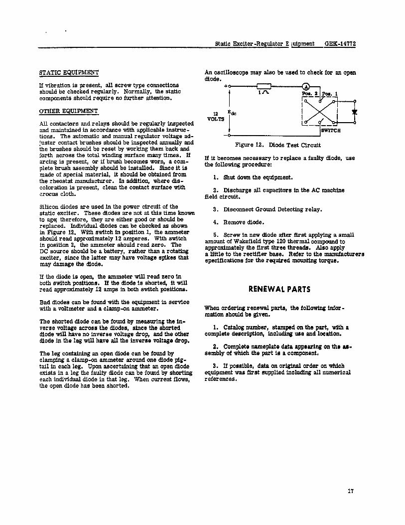
Silicon diodes are used in the power circuit of the static exciter. These diodes are not at this time known to age; therefore, they are either good or should be replaced. Individual diodes can be checked as shown in Figure 12. With switch in position 1, the ammeter should read approximately 12 amperes. With switch in position 2, the ammeter should read zero. The DC source should be a battery, rather than a rota- exciter, since the latter may have voltage spikes that may damage the diode.
If the diode is open, the ammeter will read zero in both switch positions. If the diode is shorted, it will read approximately 12 amps in both switch positions.
Bad diodes can be found with the equipment in sertice with a voltmeter and a clamp-on ammeter.
The shorted diode can be found by measuring the in- verse voltage across the diodes, since the shorted diode will have no inverse voltage drop, and the other diode in the leg will have all the inverse voltage drop.
The leg contslning an open diode can be found by clamping a clamp-on ammeter around one diode pig- tail in each leg. Upon ascert&ning that an open diode exists in a leg the faulty diode can be found by shorting each individual diode in that leg. When current flows, the open diode has been shorted.
An oscilloscope may also be used to check for an open diode.
v&s
Figure 12. Diode Test Circuit
If it becomes necessary to replace a faulty diode, use the following procedure:
1. Shut down the equipment.
2. Discharge all capacitors in the AC machine field circuit.
3. Disconnect Ground Detecting relay.
4. Remove diode.
5. Screw in new diode after first apply@ a small amount of Wakefield type 120 thermal compound to approximately the first three threads. Also apply a little to the rectifier base. Refer to the manufacturers specifications for the required mounting torque.
RENEWAL PARTS
When ordering renewal parts, the following infor- mation should be given.
1. Catalog number, stamped on the part, with a complete description, including use and locatlon.
2. Complete nameplate data appearing on the as- sembly of which the part is a component.
3. If possible, data on original order on which equipment was first supplied including all numerical references.
17
GEK-147’72 Static Exciter-Regulator Equipment
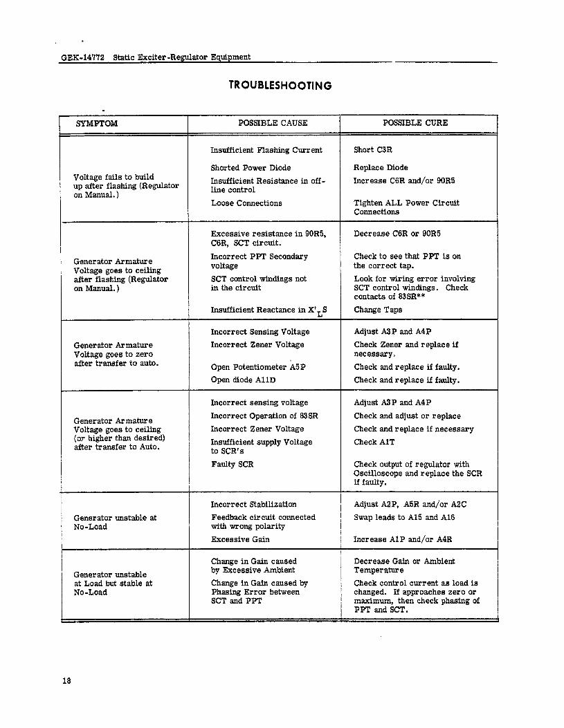
TROUBlESHOOTiNG
.
SYMPTOM POSSIBLE CAUSE POSSIBLE CURE
Voltage fails to build up after flashing (Regulator on Manual. )
Insufficient Flashing Current
Shorted Power Diode Insufficient Resistance in off - line control Loose Connections
Short C3R
Replace Diode Increase C6R and/or 90R5
Tighten ALL Power Circuit Connections
Decrease C6R or 90R5
Generator Armature Voltage goes to ceiling after flashing (Regulator on Manual.)
Generator Armature Voltage goes to zero after transfer to auto.
Generator Armature Voltage goes to ceiling (or higher than desired) after transfer to Auto.
Excessive resistance in 90R5, C6R, SCT circuit. Incorrect PPT Secondary voltage SCT control windings not in the circuit
Insufficient Reactance in XfLS
Incorrect Sensing Voltage Incorrect Zener Voltage
Open Potentiometer X5P Open diode Al 1 D
Incorrect sensing voltage Incorrect Operation of 83SR Incorrect Zener Voltage Insufficient supply Voltage to SCR’s Faulty SCR
Check to see that PPT is on the correct tap. Look for wiring error involving SCT control windings. Check contacts of 83SR** Change Taps
Adjust A3P and A4P Check Zener and replace if necessary, Check and replace if faulty. Check and replace if faulty.
Adjust A3P and A4P Check and adjust or replace Check and replace if necessary Check AlT
Check output of regulator with Oscilloscope and replace the SCR if faulty.
Generator unstable at No-Load
Generator unstable at Load but stable at No-Load
Incorrect Stabilization Feedback circuit connected with wrong polarity Excessive Gain
Change in Gain caused by Excessive Ambient Change in Gain caused by Phasing Error between SCT and PPT
Adjust A2P, A5R and/or A2C Swap leads to Al5 and Al6
1 Increase Al P and/or A4R
Decrease Gain or Ambient Temperature Check control current as load is changed. If approaches zero or maximum, then check phasing of PPT and SCT.
18
ua
-
c
(X3)
I-----
-e----
--J
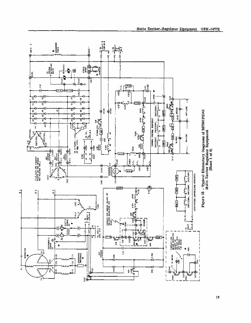
Figu
re
13 -
Typ
ical
El
emen
tary
D
iagr
ams
of 3
S750
1FS1
41
Stat
ic E
xcite
r R
egul
ator
Eq
uipm
ent
(She
et 1
of
4)
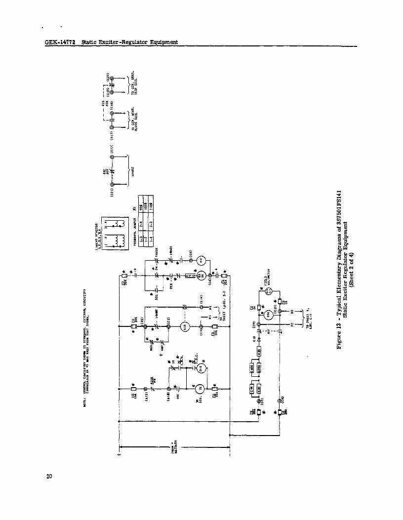
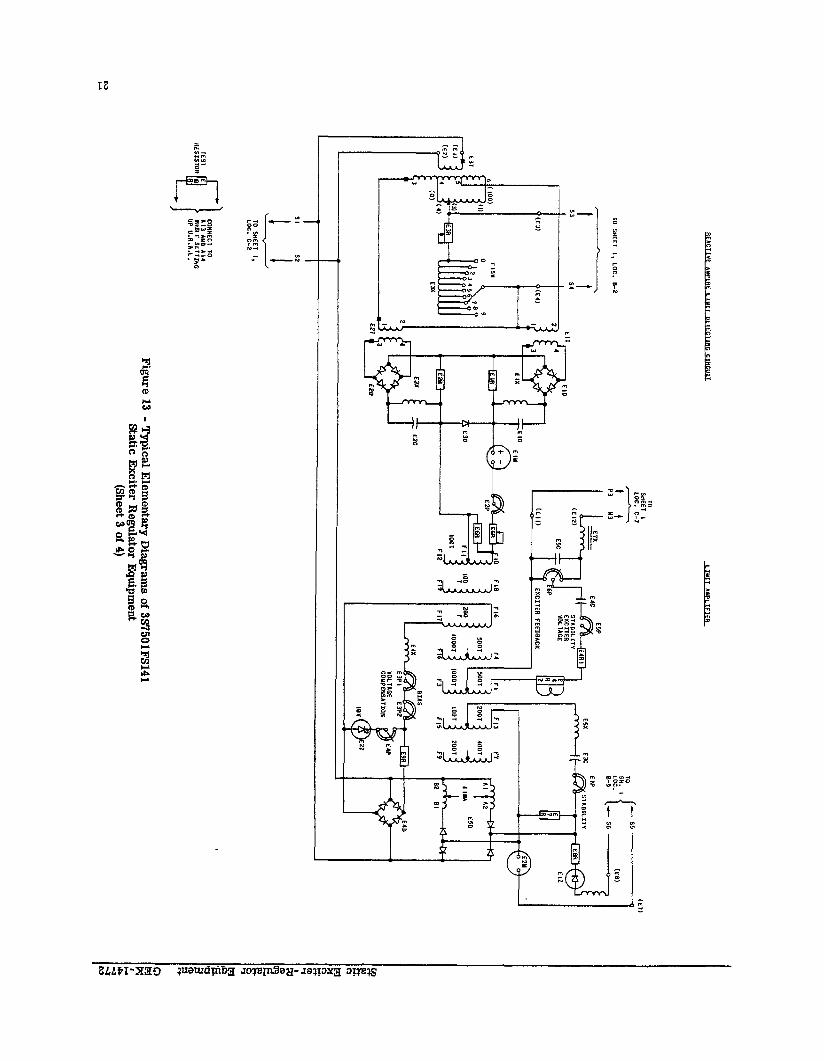
Figu
re
13 -
Typ
ical
Elem
enta
ry
Diag
ram
s of
3S7
5OlF
S141
St
atic
Excit
er
Regu
lator
Eq
uipm
ent
(She
et
2 of
4)
I-4 N
I I
! 1
GEK- 14172 Static Exciter -Regulator Equipment
ZENER DIODE, 36 VOLT I25 “A, 440212755.004 TRAHSF04YER, 2,o VoLt PRI., 160 VOLT SEC., RECTIFIERS, 4402l2741-009, C35E SIT”RIBLE REI\CTORS. 440219901-001 REACTOR, 3950504P11, 20 H., 25 YA DC 9EICTOR ,,a2,06,5-001, 3.9 H., 375 “A DC RHEOSTlt, 7, OH”, 75 lATl RESISTOR, 100 OH”. 10 WTT RES*S*OR, 4100 OH”, 10 UTT
RESISTOR. 10,ooll OH”, 10 MT1 RESISTOR, 22 000 OH”, IO lAT1 RESISTOR I do0 OH” 10 .ATT RESISTOR: do OH”, lo *ATT RESISTOR, 200 OH”, 20 WATT RESTSTOR, 1,200 OH”, 20 “lTT POTENTIOYETER, 5000 OH”, 50 VATT POTEHTIOUETER, IO 000 OHY, 50 lATT POTENTIOYETER, 254 OH”, 25 WATT POTENTIOMETER, 250 OH”, 25 UTT POTEHTrnYETER, 75 OH”, 25 “ATT POTENT~OOYETER, 2 OH”, 75 #ATT CIPACITOR, 50 “PD., 600 WDC CAPACrrOR, IO YPD., 600 l”OC CAPACITOR, 20 YFB., 600 *“DC RECffFIER, IN1697 RECTTPIER, II 12os* REICTOR, ,,S219991-PO,, I.5 H., 200 “I DC P”S”0”TrON, CRIO4A0IOZ 440209431 44820,157
440,,40,5-00 I
i12OHI*DI
E IS0 10 POSITION TAP SlITCH
:AY2* RESTSTOR, 200 OHYS, I30 UATTS RESISTOR, 9.6 OHMS
EVR E IC,EZC :: I-E3Cg
:;;2;gc3 E3Pi
:::’
RESISTOR, io,ooo OHYS, 95 I*TTS RESISTOR, RESISTOR, 20 246 000 owa, OHYS 04 95 IITTS SLTTS
RESISTOR, 47 OHYS, 20 WTTS 4ESISTOR, 510 OHYS, 95 IATTS RESISTOR. 390 OHUS ES \1*ns 4EfTSTOR, ,OOJ OHYS, 95 **rrs CAPACITOR, o., WI. 2000 ““DE CAPACITOR, CAPACIIOR, 500 30 IIFD, YFD, 600 250 l”DC ‘Iwc
C*P*CITOR IO “PD 600 ““DC PorrNrmuhER, sod OHUS, 50 #AlTS, lIRE SOUND POmtTIOUETES, 2500 OHMS, 50 w*ns, rlRE lOUNO POTENTlOYETER, 300 OHUS, 50 1ATTS, lfRE IOUND POTENTIOUETER, 150 OHMS, 5C "ATTS, *IRE MUNO POTENTIOYETER IOK OHUS, 50 *ATiS, "IRE YO"ILD VCTIFIER, 3d”, PI”, I.25 *UPS IX, 6RSZIPD61CF RECTIFIER, s!“, PI”, 1.25 &UPS DC, 6RS25PDI*DFI SECTIPIER, 490”, PI”, 3 AMPS OC, *J*4IlESl*Dl
RECTIFIER, 490”, PI”, 3 IUPS DC, ,J*,,,EY,*D, TRANSPORYER, “*“IABLE, I I%, INPUT, o-1‘0”. OUTPUT, SO,60 CYCLE TRAWSFORUER, IIW, PRI., II,‘,. SEC., 075 WA, 50/60 CYCLE C*P*EImR. I “PD. 600 WDC
YFD 600 ““DC R sdoo OHS, 50 mm
-u-d “ADO 0 WDC ER, 130~. PRI., w2/69/3, SEE., 100w
O/60 CYCLE EICTOR. 2.5 HENRIES. LSX16585
I” - “ASTEA CONTROL RELAY-TIYE DEL*”
22 - EYCTTER “OLTAOE TIUER
2EX - A”Y. RELAY TO 2E
, - UASTER COWTROL RELAY
,,HAX - PICKUP LT 50% SPEED, DROPO”T AT 25% SPEED
,4Hux - PICKUP AT 20% SPEED, DROPOUT AT 2% SPEED
I‘“% - PICKUP 4, 95% SPEED, NORUAL TRW AT 75% SPEED it CUTS OFF PVC‘. IUYEDIATE DROWUT ON ELlEROEHCY TRIP.
I,%” - PZCKUP IT 9,s SPEED, DROPOUT *T 90% SPEED
210 - OENERATOR “bDER”OLTAGE RELAY
520x - OENERATOR BREAKER 4”XILllRY RELlY
59E - 0”ER”OLTAOE RELlY
96c - GENERLTOR DIFFERENTIAL RUlY
am - TRANSFORUEP DIFFERENTlAL RELAY
94 - PICKVP ON bORY*L SHUTWIN
9354 - “OLTNX RECUUTOR CONTROL - TRIHSFER REUY
-lEL
+ - TP USED
cl3 - INSTRWENT TRAHSFORYERS ARE SHo”N COHHECTED
FOR PHlSE SEQUENCE 1-2-3. IF OENERATOR “15 ;;W”,~“’ PHASE SEQUENCE, REVERSE CT SECONDARY
* - YorF”RNTSHED 8” O.E. co.. I*YNESsoRO
H.S. - INDICATES ST”0 ENP OF RECTrFIER CONNECTED TO “EIT smx.
@ - INDICAlES CdSTOYER’S ?ER”*N*L SQARP CONnECTION
Figure 13 - Typical Elementary Diagrams of 3S7501FS141 Static Exciter Regulator Equipment
(Sheet 4 of 4)
22

NOTES
ALABAZUA t Blrminghpm 35205 . . 2151 Hlghlwd Aw.
*t : Mobtle 38808. . 1111 S.Beltlhe HIghway
ALASKA t Anckwpse 99601. . . . . 115 Whttnay Rd.
LoulSlMA + BaWn ROU@ 7OaO5. . a312 Flortda Blvd.
*t t Sew Orle#.“s 70125. . 4147 Euharr BLvd. .r Shreveport 71104 . 2620 Cente”u’y Btvd.
+ Mmroe 11201 . . . . . 1028 Sortk 6th St.
OKLAHOMA .t OWckoms. CLN 13106. . 2000 C&se,, Blvd.
+ l-ulna 74 105 P 0. Box 7646, Soutkaldr St&
OREGON
* : t E”g*rl* 91401 Portland 97216
. . . . . . . . 1170 PewI St. . . . . . , . a929 NW 29th Ave.
MARYLAND *t t BUtmore Zl201 . . . . 1 N. Chu’laa St. ZIZONA
PkcmnlX 85012 . . 3550 N. Central Ave. t Tucmn BS718. . . . . : : .151 S.Tuc~n Bl”d. PENNSYLVANlA . Ahntom 18102 . . . . . . 1444 Hamilton St. *tt Phllad~lpkla 19102 . . . 3 PI”” Cmur Plus *+ Ptttabvrgk 15222 , .300 Etk Avenue Bldy.
htAS3ACliUSETTS *t t Welmlay 021s 1 . . . . 1 Wa~ktqtrm St.
ARKANSAS + Jorti Llttla Rack 72119. . . . .lZO MaIn St. F*T” Dbtroit la202 . . . . . 100 AntoLnltte St
: JOCkSOn 49201 . . . . . . a10 W. FrMtln St. S#nprW Pm307
,.... . 1908 Second National Bnak Bl@.
cAL1FatNIA ‘t t LOI Ax&es 90054 . . . . , .211 N. VLE,,., St.
t Palo Alto 91303 . . . . . 960 EM Anwnto Rd. t sacrnmenm 95808.. . . . . . 2407 J St. t 98,. DleSo 92105 . . . . . . . . 2560 First AM.
. f San mnct8cO Mll9. . . . 53 mtinrne St.
. Vernon 90068. . . . . . . 3055 E. 44tk St. COLORADD *t Denwr 80200. . . . . . 201 Unlverslty Blvd.
CONNECTICUT -+ Marlden 06450. . . . . . . 1 Prestige Dr.
SOUTH CAROLETA t t Columbln 29204 . . . 2100 MLddlcbvrg Dr. t Greentill. 299001. . 41 No. Plwr,r,tkurS Dr.
MDWESOTA Tf Duluth 55802 . . 300 W. Sup&or S,.
*tt Mtrmeq.dL~ 55416 1500 Ltl?c Drtw So.
TENNEXiEE *t cmttaMoSn31411
. ..*...*. +
5800 Bldg, Eugata C~nt.r Xemphia 39130. . . . .a385 Air-y, Blvd.
MIsSCUR *t Kansas cuy e4199. . . . . . . 911 &Ml St. *+ SL LO”,S 83101 . . . . . .lOlJ LLxUst St
?!xxAs 'T Amullto 79101 . . . . , . . , .303 Polk St. *tr Be~uxmnt 71704 . . . . . 1385 Catd.r Am : t t Corpus Ckrtltl76401. . 205 N. Chaparral St.
Dalm 75222 . . a101 stammon. Rdway *t El Pam TO945 . . . . . . . 215 N.StPnton
t Fort Word, 76102 . . . 406 w. SS”wdk St. *tt Hou8tm 7’7027 . . . . 4219 Rlckmond Ave.
t San Antnnm 78204 . . . . 434 S. Man St
UTAH t Salt L&e City 84111 . . 431 S. Tklrd East St.
VIRGINIA - r Nervport NeurS 23501 . . . . 311 MIln St.
:* Rtckmond 23230 1508 wulc.w Lawn Dr. Roanoke 24015 . 2018 Colonml Ave.
WASHINGTON *et Seattle 98188
. . . . 112 MdoYBr Put East, Tumvlla T spolanc 99202 . . . . E. 1805 Rent A”%
MONTANA t Butte 59701 . . . . . . . 103 N.wyombg St. FLORIDA
tr Jacksontitle 32203 . . . 4WO W.,Od”,c.k Dr. +t Yiami 33134 . . . . . 4100 W. FL%gler St.
‘T r Tampa 33609.. . . . . 2100 9. Lo,8 Ave.
NEBRASU -t Omaha 49102 . . . . . 409S.17tkSt.
Lltttkurn 07O41. . . . . . . . 25 E.Wtllow St. GEORGIA *t t Atlanta 30309. . .1860 PePcktrea Rd., NW
tt Sam31405 . . . . .5092 Paulaen St. NEW YORK
tt Albany 12205. . . 15 computer Drive. west *tt Buffalo 14209 . . . . d25 Delaware Ave. - t I x New York 10022 . . 641 Lemn@~n A”& . Rockester 14404 , . . . . . . 89 East Ave. * * * 8yracuse 13206 . . .3532 k&mea St
HAWAII *+ t HoMlulu 96813 . . . . . 440 Coral Sk
ILLINOIS * t f X CklcaSo SO880 . . . 640 s. cnnal St.
WDlANA
: Ennsnlle 4,705 Fort Wayne 4680’7
*t lndtanapolte 48207
NORTH CAROLINA *tt Chwlotte 28207 _ . , 141 Prondence Rd . WU”d”gtO”
Reigelwocd 38456. . . . . P 0 BOX 188
. 2709 Wzrhlngtcn Ave. . 3806s calko”” St.
. 3750 N. Meridtm St.
1039 Skate St.. Bettetiorf
. . 2300 Meadow Dr.
IOWA t Davenprt 32505
. . . P 0. Box 830.
OHIO *+ Cinctnnatt 452.06. . . 2621 Vtctorv Plnuy. *tr Cleveland 44104 . . 1000 Lakemde Aye.
:* ColumkuS 43229. . . 1110 mrae Rd. T&do43606 . . . . . 31’25 DouglasRd.
+ Youngstuwn 44507. . . 272 lndtznota Ave.
WEST YIRGEHA *t Charleston 25326 .3OE MacCorkle Ave., SE
WISCONSM . *ppk2an 54911 3003 west College Dr
t t M~lwa”liee 53202 . $15 E %X,ekt$an St KENlVCKY
t IAuisvIue 4oa18
GENERAL ELECTRIC SERVICE SHOPS WHEN YOU NEED SERVICE These GE Sertice Shops wttl repzw. re- tses. Latest faerory methods and Senume GE renewa, parts zre wed to condttlon. md rebuild your eteetrlc apparmus. The fac~ltttes are avarlable mat”tain perlormance oi you* Equipment. For iuu ,nformarlon *bout these day and night, seven days a week, for work 8” the shops or on your Prem- servlce8. mntact “ “ “ r nearesr VJrvlce *Ilop or Sales m,ce
ALABAMA . - Blrm,nghm 35211 . .1500 Mims Ave. ,S.W.
. M~oktle 36608. . . . . . . 721 Lakeside Dr.
LOUISIANA . mom Rouge 70814 . 10955 Nor* Dual a.
. * New Orleans 70114. . 1115 DeArmas St.
MARYLAND l * Baltimore 21230 . . . 930 E. Fort Ave.
OKLAHOMA - TYLY 74146. . . 5220 s. 100th East AYe.
OREGON l Eugelle 07402 . . . . . . . 570 wuson St.
l * Portland 97210 . 2727 Yw 29tk AYC. ARIZONA
l ,Pkoen!xl Glen&& 85019.4011 W.Colter St. l Phoenix 85019 . l Tucson 65113 . : .
36.40 w clarendon St. 2942 So.PB1” Verde Ave. PENLSYLVANIA
0 Allentom 18103 . . . 668 E. Hi6klar.d St. ’ IDetlu%re Valley)Ckercy H,lI N J OS034
. . . . . . . . 1190 E.~larlta” Pike l JOhnstown 15802 . . . a41 oak S t . l Pklladelphta 19124 1040 Esst Erie Ave.
l * lPtDIlb”rgk, West MlIflin 15122 . . 4430 Butterlmlk “allow Rd
l York 17403 . . . . . . 54 N Harrison St
. . . . . . . . 3964 Mystic Valley Pkwy CALIFORNIA l Los Ar&an $0301 5900 Stanford A”e
l (Lm .b&es) Anakelm s3805 . . . . . . . . . 3601 E. LzPalms. Ave.
* (LOS AngelOSl klgtewxd 90301 . . . . . . . 228 W. Florence Ave.
. sacrament0 $5814 , . . , 99 North 17tk St. l * (San Franetsco, &kb‘“d 94608
. . . . . . . . . . . . . . . 1650 34tk St.
MICHIGAN l * _ (Detrwtl Rlvervlew. . 18075 Kravse Ave.
. FHnt 4a505 1506 E carpenter 84.
MINNESOTA . hrlutk 5580, ,5Oti A”e W & StL.o”,s Bay
. * ~lt”neapol,s 55430 2025 49th A”e. , N SOUTH CAROLINA l iCkarlss‘,r.i No ChYlerton 28401
. . 2*90 Debunmr at. . - l‘mazs City 64120 . 3525 Gardner A”% . - 3‘ LO”,S 63110 1115 East Rd
5EW JERSEY * New munswlCk 08902 3 Laurence at.
YEW 3IExICO l 4Lhuquerque an09 1420 ‘.lcLeod Rd. ?iE
‘JEW YORK . 4lbany 13205 1091 Cenvat Ave
. - ~Butfalo, Tonawanda 14150 115 Yilens Rd l iLong Island) Old B&page tlSO4
. I . . 163 BetkpaSe-Sweet Hollow Rd . w?w York Cltyl AOlTk Bergen N. J 01012
.,, . . 8001 Tomeue iwe. - isew York Cuyl’Cl& N d. 07012
* _ %kenecmdy 12365 . 9 Brighton Bd.
1 Rl”W Rd. 0 avracuse 13208 . 1015 E.H,avafha BLti
COLORADQ . * Denver 80205. . . . . . . . 3353 Lar‘mer St. TEBNESSEE
9 Knoxnlle 57914 . 3621 Governor Jokn &tiler Hwy.
9 ulempmr 3810, 708 Ncrdl vatn St. . CONNECTICUT
l * :ao”thingto”, PlMtsnlle 06419 . . . . . . 370 Atwater St
FLORrnA l * Jack%nnlle 32203 . 2020 w Beaver St.
l ~Mtaml, lilaleak 33010 1062 Easi 28tk St. l * T~mpl33601 . . . l%h&GrxXSts
Beaumont xi05 1490 W Cardinal Dr. Corpus Cknsh 78401 115 waen St. Dallas 75235 3202 Manor way Houston 11036 5534 Harvey Wtlsan Or HOUSID” 77036 . 6916 Harwt” Dr &I,dland 79101 . 704 s J”nnsta” st. GEORGL,
l ,AthB, Ckunblee 3034 1 5035 Peachtree Indutrtal-Blvd.
* AtI%,= . . . . 2319 John Glen” Dr.
. UTAH
* * Salt Lake City 84110 301 s 7tk west St.
VmGniM q * R,ekmond 23224
- Roan& 24013 . 1403 Ingram AYe.
1004 ruver A”%, SE
ILLOIOIS . * Chicago 50835 . 6045 S.Nofflngham Ave.
NDWiA l Evans”lllle 47111 401 N Congress AYL . Ft Wayne 46803. 1731 Edsalt AYe. l Hammond 46320
. 1138 leak Place
. * nldwnap01,s 46222 ‘1140 w Vermont 51.
>ORTH CAROLNA . * Charlotte 28208 . 2323 Tknft Rd WASHTNGTON
. * Seattle 96134 5422 Fuw Ave.. sourk l Spokane 99211 E 4323 MlSS”” S t mm
. .A!uon lCamo”l 44720
* * Ci&matt 46202 i900 Wki~le &“e S Ik
.444 West 3rd St .*- Geveland 44126 . . 4471 East 49th St
. Columbus43228 . . mo Bunfley ti. * * T&d043605 405 Dearoorn Ave
* Yo”ngstow” 44507 272 E. Indianon Ave.
WEST VDIGDU . * ckar,est”n 25328 .306 WacCaWe A”e SE
WISCONSIN . ~ppteto”, Menasha 54910 Ii25 il?.cme 3. * i1,iwrulue 53201 235 W Okh,numa Ave.
IOWA l Dx”eqmrt, Battendorl 52122 1025 State St
KENTUCKY l LoulsfUe 40209 . . 3900 Crlttenden Dn”e
! . ELecP,cai,,,eckan,ul Sernce Shop * hstrumenetlon Shop - Spec~ll Uan”laCt”n~ Shop
DRIVE SYSTEMS PRODUCT DEPARTMENT GENERAL ELECTRIC COMPANY, WAYNESBORO, VIRGINIA 22980
2-72 17501