Embed Size (px)
Citation preview
Lecture 17
February 23, 2018
Statics - TAM 210 & TAM 211

Announcements Monday’s lecture: watch for Piazza announcement over weekend for possible
change
Concept Inventory: Ungraded assessment of course knowledge Extra credit: Complete #1 or #2 for 0.5 out of 100 pt of final grade each, or
both for 1.5 out of 100 pt of final grade #1: Sign up at CBTF (2/26-3/1 M-Th) #2: (4/2-4 M-Th) 50 min appointment, should take < 30 min
Upcoming deadlines: Quiz 3 (2/21-23)
Sign up at CBTF
Monday (2/26) Mastering Engineering Tutorial 7
Tuesday (2/27) PL HW 6
Thursday (3/1) WA 3 See enhanced instructions

Chapter 6: Structural Analysis

Goals and Objectives• Determine the forces in members of a truss using the method of
joints
• Determine zero-force members
• Determine the forces in members of a truss using the method of
sections
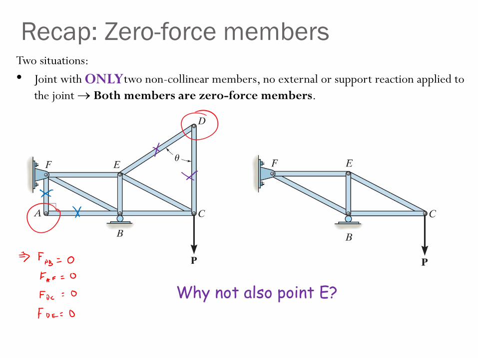
Two situations:
• Joint with two non-collinear members, no external or support reaction applied to
the joint Both members are zero-force members.
Recap: Zero-force members
Why not also point E?
ONLY
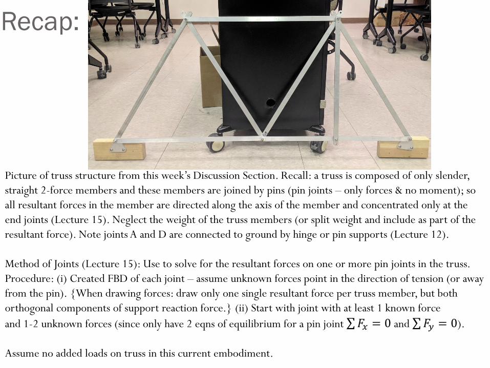
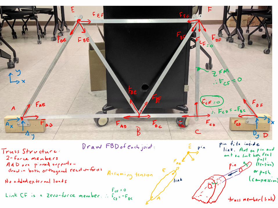
Picture of truss structure from this week’s Discussion Section. Recall: a truss is composed of only slender,
straight 2-force members and these members are joined by pins (pin joints – only forces & no moment); so
all resultant forces in the member are directed along the axis of the member and concentrated only at the
end joints (Lecture 15). Neglect the weight of the truss members (or split weight and include as part of the
resultant force). Note joints A and D are connected to ground by hinge or pin supports (Lecture 12).
Method of Joints (Lecture 15): Use to solve for the resultant forces on one or more pin joints in the truss.
Procedure: (i) Created FBD of each joint – assume unknown forces point in the direction of tension (or away
from the pin). {When drawing forces: draw only one single resultant force per truss member, but both
orthogonal components of support reaction force.} (ii) Start with joint with at least 1 known force
and 1-2 unknown forces (since only have 2 eqns of equilibrium for a pin joint σ𝐹𝑥 = 0 and σ𝐹𝑦 = 0).
Assume no added loads on truss in this current embodiment.
Recap:
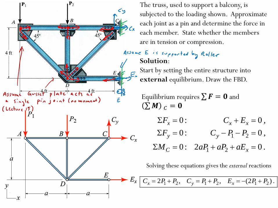
The truss, used to support a balcony, is
subjected to the loading shown. Approximate
each joint as a pin and determine the force in
each member. State whether the members
are in tension or compression.
Solution:
Start by setting the entire structure into
external equilibrium. Draw the FBD.
1 2
1 2
0 : 0 ,
0 : 0 ,
0 : 2 0 .
x x x
y y
C x
F C E
F C P P
M aP aP aE
1 2 1 2 1 22 , , (2 ) .x y xC P P C P P E P P
Solving these equations gives the external reactions
Equilibrium requires σ𝑭 = 𝟎 and σ𝑴 𝐶 = 𝟎

Next, start with a joint, draw the FBD, set it into force equilibrium only, and move to the next
joint. Start with joints with at least 1 known force and 1-2 unknown forces.
1
2
11 2
0 : 0 ,
0 : 0 .
x AB AD
y AD
F F F
F P F
11 1 12
2 , 2 .AD ABF P F P P
For example, start with joint A:
Joint B:
2
0 : 0 ,
0 : 0 .
x AB BC
y BD
F F F
F P F
1 2, .BC AB BDF F P F P
Joint C:
11 22
11 22
0 : 2 0 ,
0 : 0 .
x BC CD
y CD
F F F P P
F F P P
1 2 1 1 2
1 2
2(2 ) 2( ) ,
2( ) (check) .
CD
CD
F P P P P P
F P P
Joint D: only needed for check
Joint E:
1 1
2 2
1 1
2 2
0 : 0 ,
0 : 0 .
x AD CD DE
y AD BD CD
F F F F
F F F F
1 11 1 2 1 22 2
1 11 2 1 22 2
2 2( ) (2 ) ,
2 2( ) 0 (check) .
DEF P P P P P
P P P P
1 2 1 2 1 22 , , (2 ) .x y xC P P C P P E P P
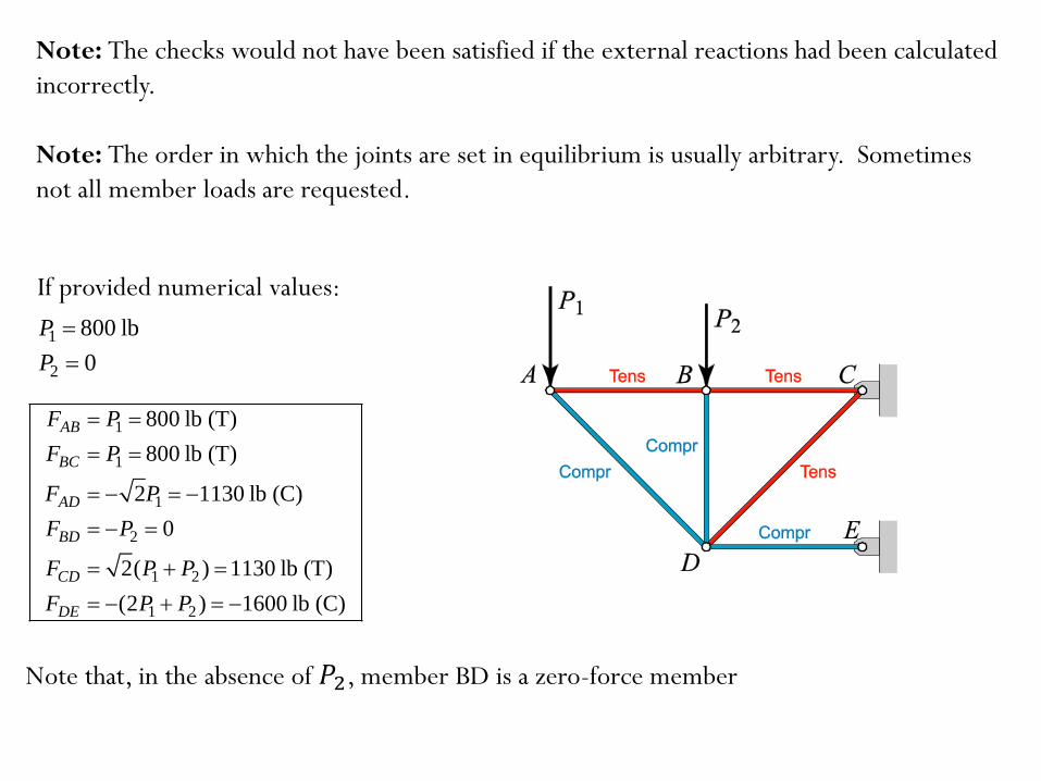
Note: The checks would not have been satisfied if the external reactions had been calculated
incorrectly.
Note: The order in which the joints are set in equilibrium is usually arbitrary. Sometimes
not all member loads are requested.
1 800 lbP
2 0P
1
1
1
2
1 2
1 2
800 lb (T)
800 lb (T)
2 1130 lb (C)
0
2( ) 1130 lb (T)
(2 ) 1600 lb (C)
AB
BC
AD
BD
CD
DE
F P
F P
F P
F P
F P P
F P P
Note that, in the absence of 𝑃2, member BD is a zero-force member
If provided numerical values:
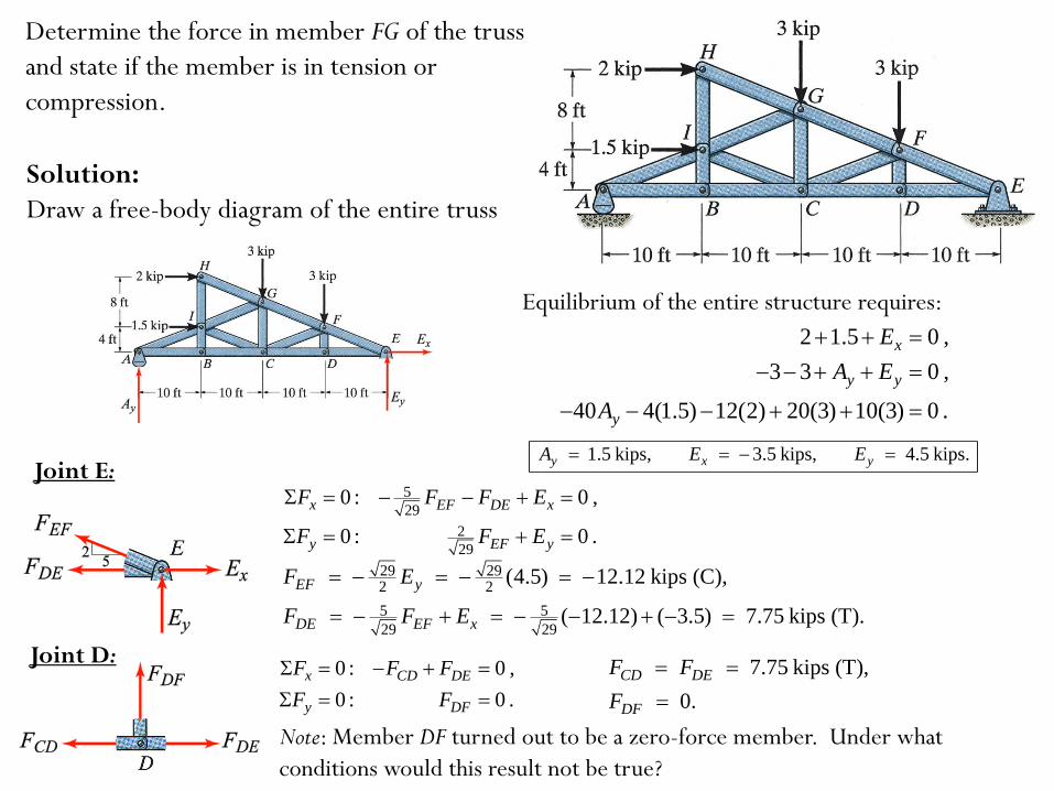
Determine the force in member FG of the truss
and state if the member is in tension or
compression.
Solution:
Draw a free-body diagram of the entire truss
0 : 2 1.5 0 ,
0 : 3 3 0 ,
0 : 40 4(1.5) 12(2) 20(3) 10(3) 0 .
x x
y y y
E y
F E
F A E
M A
Equilibrium of the entire structure requires:
1.5 kips, 3.5 kips, 4.5 kips.y x yA E E Joint E:
5
29
2
29
0 : 0 ,
0 : 0 .
x EF DE x
y EF y
F F F E
F F E
29 292 2
5 5
29 29
(4.5) 12.12 kips (C),
( 12.12) ( 3.5) 7.75 kips (T).
EF y
DE EF x
F E
F F E
0 : 0 ,
0 : 0 .
x CD DE
y DF
F F F
F F
7.75 kips (T),
0.
CD DE
DF
F F
F
Note: Member DF turned out to be a zero-force member. Under what
conditions would this result not be true?
Joint D:
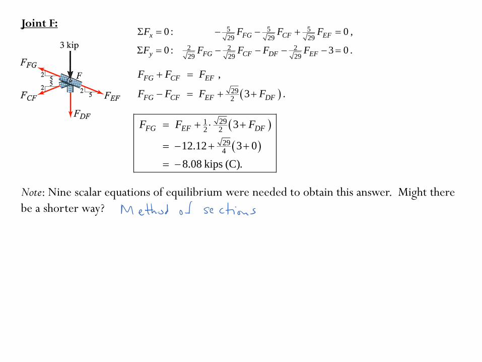
Joint F:5 5 5
29 29 29
2 2 2
29 29 29
0 : 0 ,
0 : 3 0 .
x FG CF EF
y FG CF DF EF
F F F F
F F F F F
292
,
3 .
FG CF EF
FG CF EF DF
F F F
F F F F
2912 2
294
3
12.12 3 0
8.08 kips (C).
FG EF DFF F F
Note: Nine scalar equations of equilibrium were needed to obtain this answer. Might there
be a shorter way?
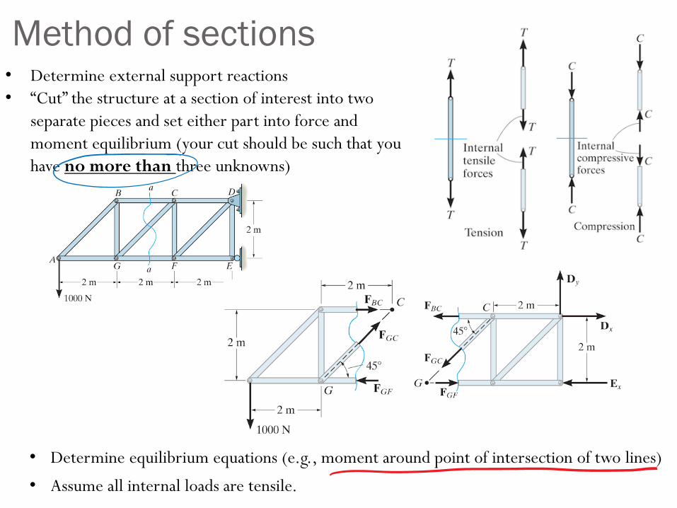
Method of sections• Determine external support reactions
• “Cut” the structure at a section of interest into two
separate pieces and set either part into force and
moment equilibrium (your cut should be such that you
have no more than three unknowns)
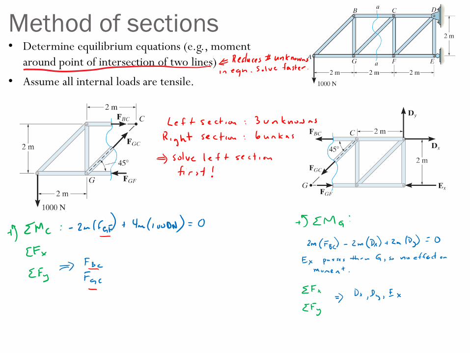
• Determine equilibrium equations (e.g., moment around point of intersection of two lines)
• Assume all internal loads are tensile.
Method of sections• Determine equilibrium equations (e.g., moment
around point of intersection of two lines)
• Assume all internal loads are tensile.
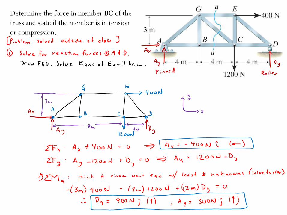
Determine the force in member BC of the
truss and state if the member is in tension
or compression.
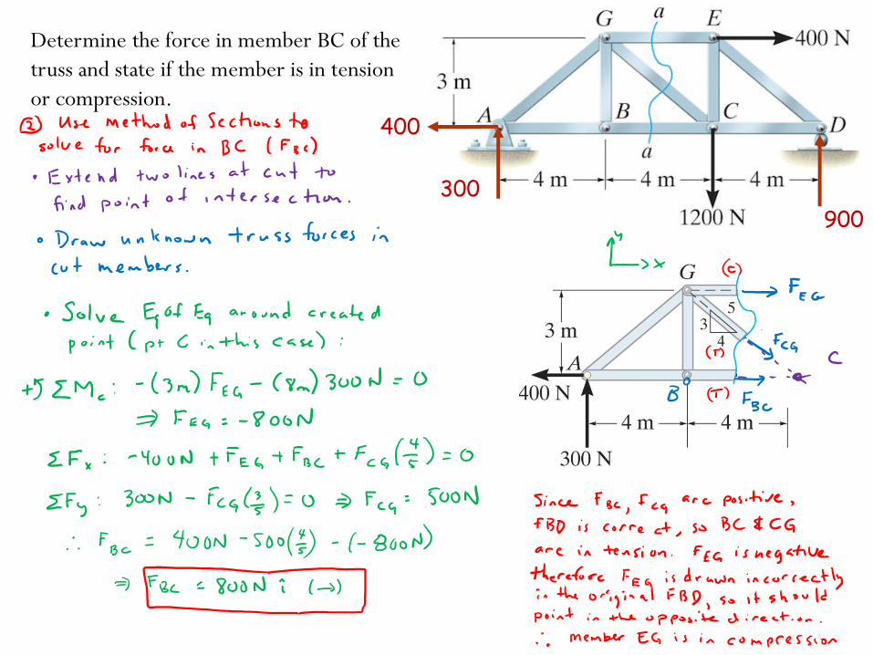
Determine the force in member BC of the
truss and state if the member is in tension
or compression.
400
300
900
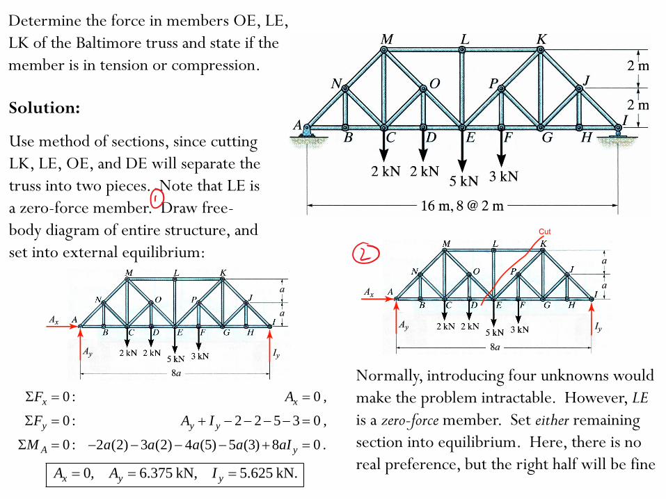
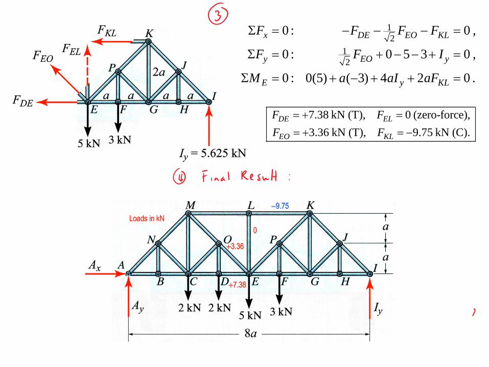
Determine the force in members OE, LE,
LK of the Baltimore truss and state if the
member is in tension or compression.
Solution:
Use method of sections, since cutting
LK, LE, OE, and DE will separate the
truss into two pieces. Note that LE is
a zero-force member. Draw free-
body diagram of entire structure, and
set into external equilibrium:
0 : 0 ,
0 : 2 2 5 3 0 ,
0 : 2 (2) 3 (2) 4 (5) 5 (3) 8 0 .
x x
y y y
A y
F A
F A I
M a a a a aI
0, 6.375 kN, 5.625 kN.x y yA A I
Normally, introducing four unknowns would
make the problem intractable. However, LE
is a zero-force member. Set either remaining
section into equilibrium. Here, there is no
real preference, but the right half will be fine
1
2
1
2
0 : 0 ,
0 : 0 5 3 0 ,
0 : 0(5) ( 3) 4 2 0 .
x DE EO KL
y EO y
E y KL
F F F F
F F I
M a aI aF
7.38 kN (T), 0 (zero-force),
3.36 kN (T), 9.75 kN (C).
DE EL
EO KL
F F
F F