Embed Size (px)
Citation preview
Status and progress of TPC detector module and prototype
Huirong Qi
Institute of High Energy Physics, CAS3rd, November, 2017, Annual Joint Meeting, IHEP
- 2 -
Outline
Physics requirements
Status of TPC module R&D
Status of TPC prototype R&D
Summary
- 3 -
Physics requirements
- 4 -
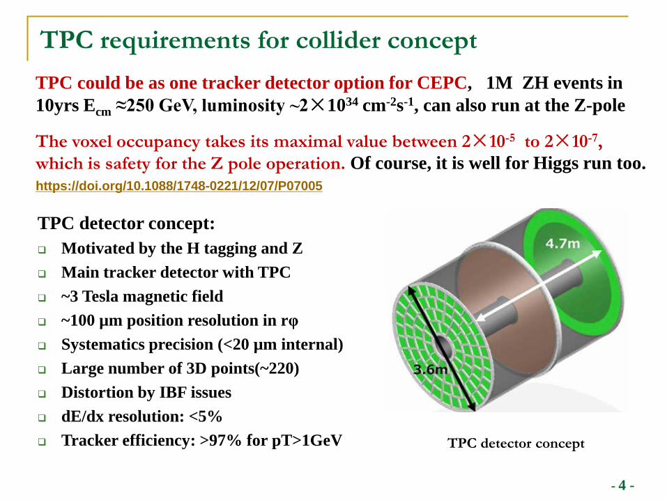
TPC requirements for collider conceptTPC could be as one tracker detector option for CEPC, 1M ZH events in 10yrs Ecm ≈250 GeV, luminosity ~2×1034 cm-2s-1, can also run at the Z-pole
The voxel occupancy takes its maximal value between 2×10⁻⁵ to 2×10⁻⁷, which is safety for the Z pole operation. Of course, it is well for Higgs run too.https://doi.org/10.1088/1748-0221/12/07/P07005
TPC detector concept: Motivated by the H tagging and Z Main tracker detector with TPC ~3 Tesla magnetic field ~100 µm position resolution in rφ Systematics precision (<20 µm internal) Large number of 3D points(~220) Distortion by IBF issues dE/dx resolution: <5% Tracker efficiency: >97% for pT>1GeV TPC detector concept
- 5 -
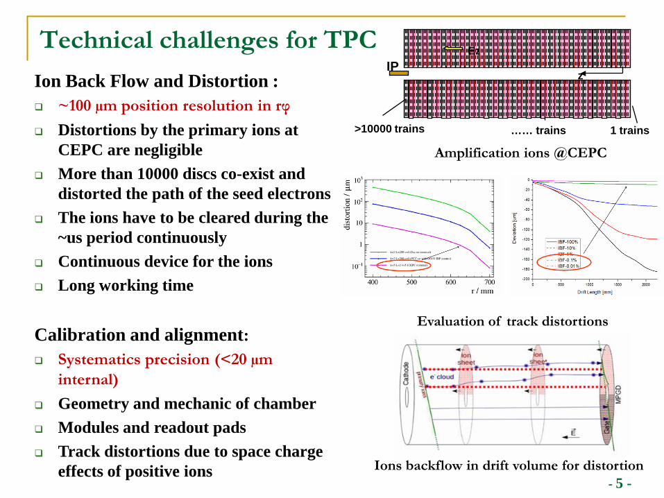
Technical challenges for TPCIon Back Flow and Distortion : ~100 µm position resolution in rφ Distortions by the primary ions at
CEPC are negligible More than 10000 discs co-exist and
distorted the path of the seed electrons The ions have to be cleared during the
~us period continuously Continuous device for the ions Long working time
Calibration and alignment: Systematics precision (<20 µm
internal) Geometry and mechanic of chamber Modules and readout pads Track distortions due to space charge
effects of positive ions
Amplification ions @CEPC
Ez r
1 trains>10000 trains …… trains
IPz
Ions backflow in drift volume for distortion
Evaluation of track distortions
- 6 -
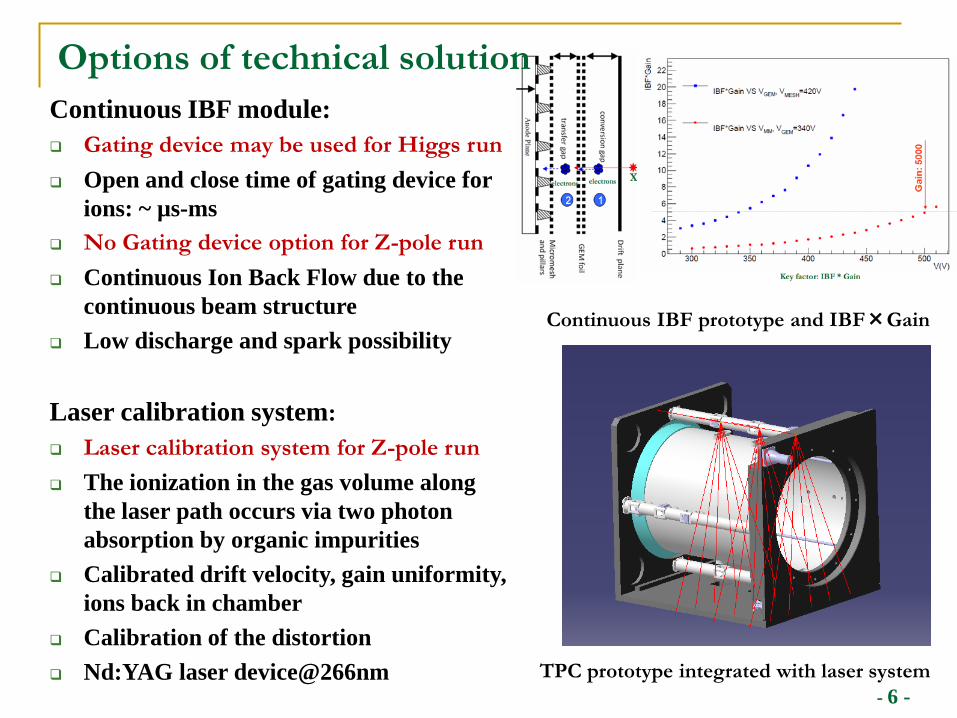
Options of technical solutionContinuous IBF module: Gating device may be used for Higgs run Open and close time of gating device for
ions: ~ µs-ms No Gating device option for Z-pole run Continuous Ion Back Flow due to the
continuous beam structure Low discharge and spark possibility
Laser calibration system: Laser calibration system for Z-pole run The ionization in the gas volume along
the laser path occurs via two photon absorption by organic impurities
Calibrated drift velocity, gain uniformity, ions back in chamber
Calibration of the distortion Nd:YAG laser device@266nm TPC prototype integrated with laser system
Continuous IBF prototype and IBF×Gain
- 7 -
Status of TPC module R&D
- 8 -
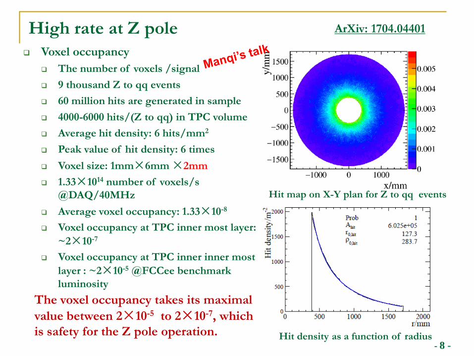
High rate at Z pole Voxel occupancy
The number of voxels /signal 9 thousand Z to qq events 60 million hits are generated in sample 4000-6000 hits/(Z to qq) in TPC volume Average hit density: 6 hits/mm2
Peak value of hit density: 6 times Voxel size: 1mm×6mm ×2mm 1.33×10¹⁴ number of voxels/s
@DAQ/40MHz Average voxel occupancy: 1.33×10⁻⁸
Voxel occupancy at TPC inner most layer: ~2×10⁻⁷
Voxel occupancy at TPC inner inner most layer : ~2×10⁻⁵ @FCCee benchmark luminosity
Hit map on X-Y plan for Z to qq events
Hit density as a function of radius
The voxel occupancy takes its maximal value between 2×10⁻⁵ to 2×10⁻⁷, which is safety for the Z pole operation.
ArXiv: 1704.04401
- 9 -
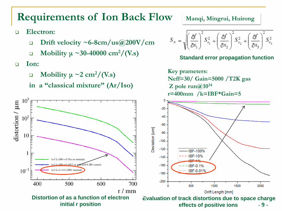
Requirements of Ion Back Flow
Standard error propagation function
Electron: Drift velocity ~6-8cm/us@200V/cm Mobility μ ~30-40000 cm2/(V.s)
Ion: Mobility μ ~2 cm2/(V.s)in a “classical mixture” (Ar/Iso)
Evaluation of track distortions due to space charge effects of positive ions
Key prameters:Neff=30/ Gain=5000 /T2K gasZ pole run@1034
r=400mm /k=IBF*Gain=5
Distortion of as a function of electron initial r position
Manqi, Mingrui, Huirong
- 10 -
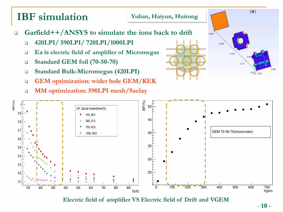
IBF simulation Garfield++/ANSYS to simulate the ions back to drift
420LPI/ 590LPI/ 720LPI/1000LPI Ea is electric field of amplifier of Micromegas Standard GEM foil (70-50-70) Standard Bulk-Micromegas (420LPI) GEM optimization: wider hole GEM/KEK MM optimization: 590LPI mesh/Saclay
Electric field of amplifier VS Electric field of Drift and VGEM
Yulian, Haiyun, Huirong
- 11 -
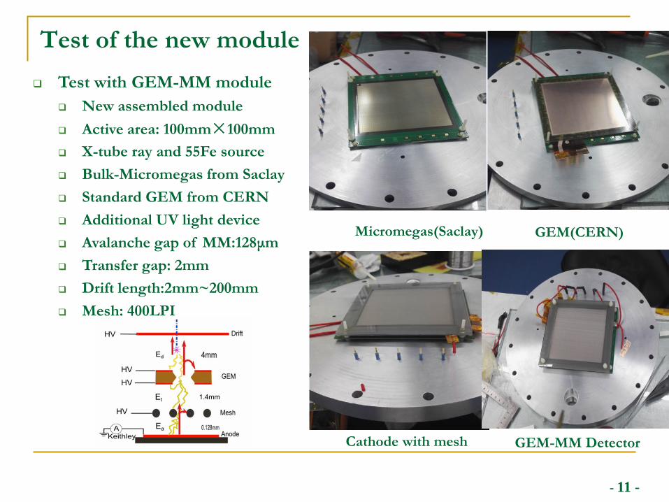
Test of the new module
Micromegas(Saclay) GEM(CERN)
Cathode with mesh GEM-MM Detector
Test with GEM-MM module New assembled module Active area: 100mm×100mm X-tube ray and 55Fe source Bulk-Micromegas from Saclay Standard GEM from CERN Additional UV light device Avalanche gap of MM:128μm Transfer gap: 2mm Drift length:2mm~200mm Mesh: 400LPI
- 12 -
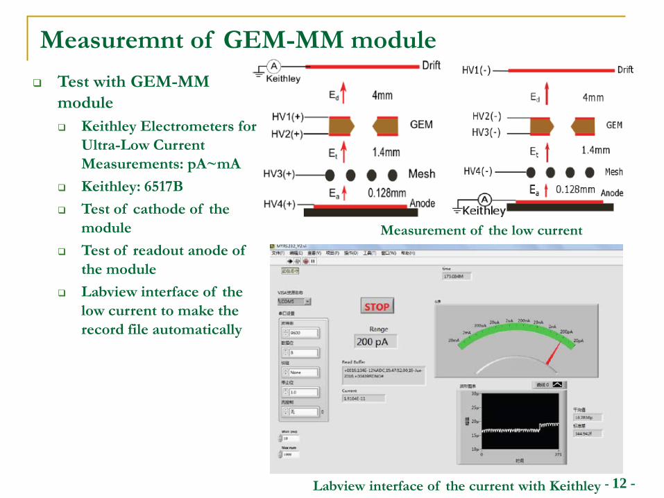
Measuremnt of GEM-MM module
Measurement of the low current
Labview interface of the current with Keithley
Test with GEM-MM module Keithley Electrometers for
Ultra-Low Current Measurements: pA~mA
Keithley: 6517B Test of cathode of the
module Test of readout anode of
the module Labview interface of the
low current to make the record file automatically
- 13 -
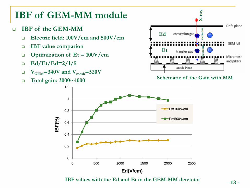
IBF of GEM-MM module
IBF values with the Ed and Et in the GEM-MM detetctot
IBF of the GEM-MM Electric field: 100V/cm and 500V/cm IBF value comparion Optimization of Et = 100V/cm Ed/Et/Ed=2/1/5 VGEM=340V and Vmesh=520V Total gain: 3000~4000 Schematic of the Gain with MM
0
0.2
0.4
0.6
0.8
1
1.2
0 500 1000 1500 2000 2500
IBF(
%)
Ed(V/cm)
Et=100V/cm
Et=500V/cm
Et
Ed
- 14 -
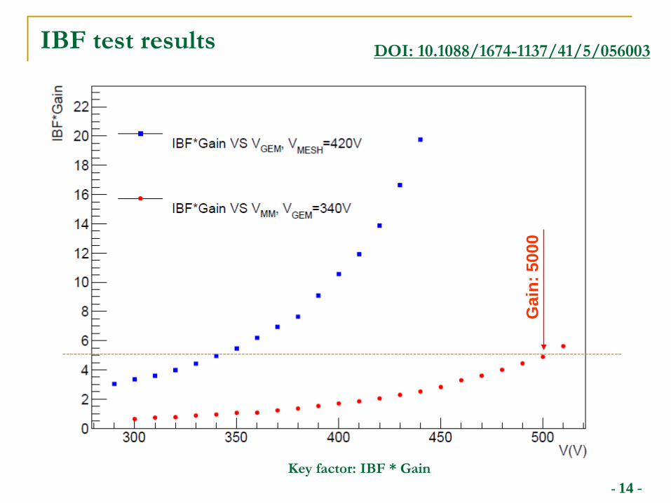
IBF test results
Gai
n: 5
000
Key factor: IBF * Gain
DOI: 10.1088/1674-1137/41/5/056003
- 15 -
Status of TPC prototype R&D
- 16 -
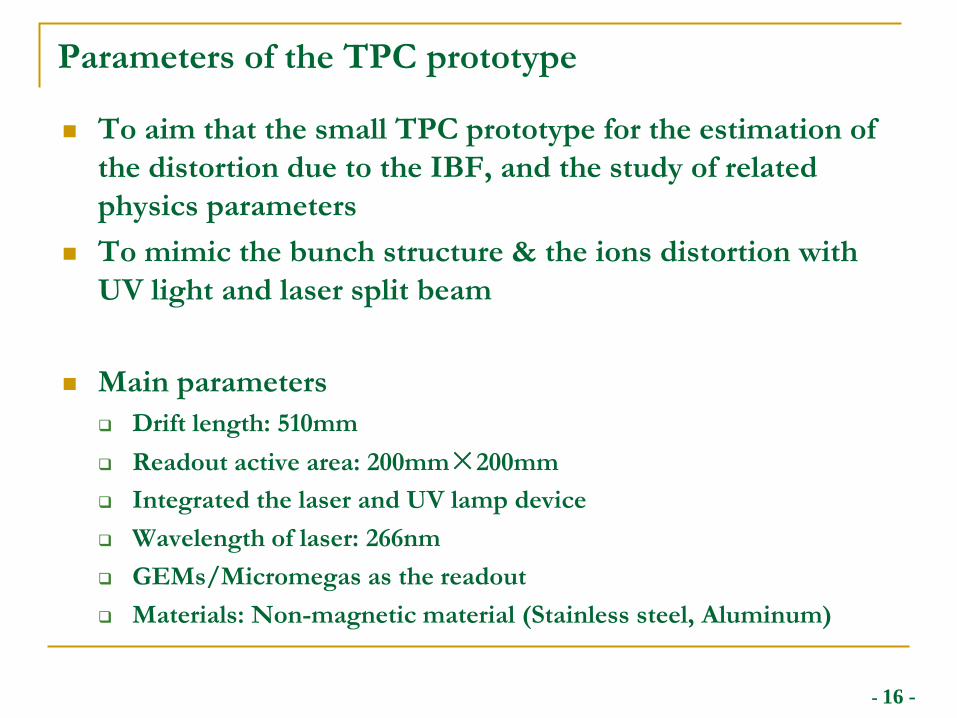
Parameters of the TPC prototype
To aim that the small TPC prototype for the estimation of the distortion due to the IBF, and the study of related physics parameters
To mimic the bunch structure & the ions distortion with UV light and laser split beam
Main parameters Drift length: 510mm Readout active area: 200mm×200mm Integrated the laser and UV lamp device Wavelength of laser: 266nm GEMs/Micromegas as the readout Materials: Non-magnetic material (Stainless steel, Aluminum)
- 17 -
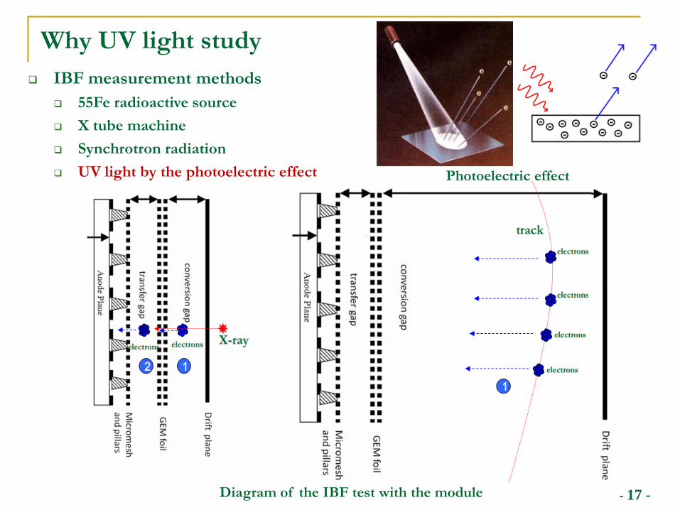
Why UV light study
Diagram of the IBF test with the module
IBF measurement methods 55Fe radioactive source X tube machine Synchrotron radiation UV light by the photoelectric effect Photoelectric effect
- 18 -
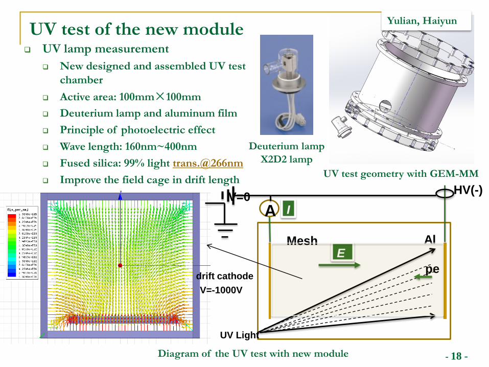
UV test of the new module
Diagram of the UV test with new module
Deuterium lampX2D2 lamp
UV lamp measurement New designed and assembled UV test
chamber Active area: 100mm×100mm Deuterium lamp and aluminum film Principle of photoelectric effect Wave length: 160nm~400nm Fused silica: 99% light trans.@266nm Improve the field cage in drift length
HV(-)
Mesh
A
E
I
UV Light
Al
pe
V=0
drift cathodeV=-1000V
UV test geometry with GEM-MM
Yulian, Haiyun
- 19 -
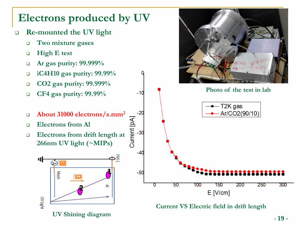
Electrons produced by UV Re-mounted the UV light
Two mixture gases High E test Ar gas purity: 99.999% iC4H10 gas purity: 99.99% CO2 gas purity: 99.999% CF4 gas purity: 99.99%
About 31000 electrons/s.mm2
Electrons from Al Electrons from drift length at
266nm UV light (~MIPs)
Current VS Electric field in drift length
2
1
UV Shining diagram
Photo of the test in lab
- 20 -
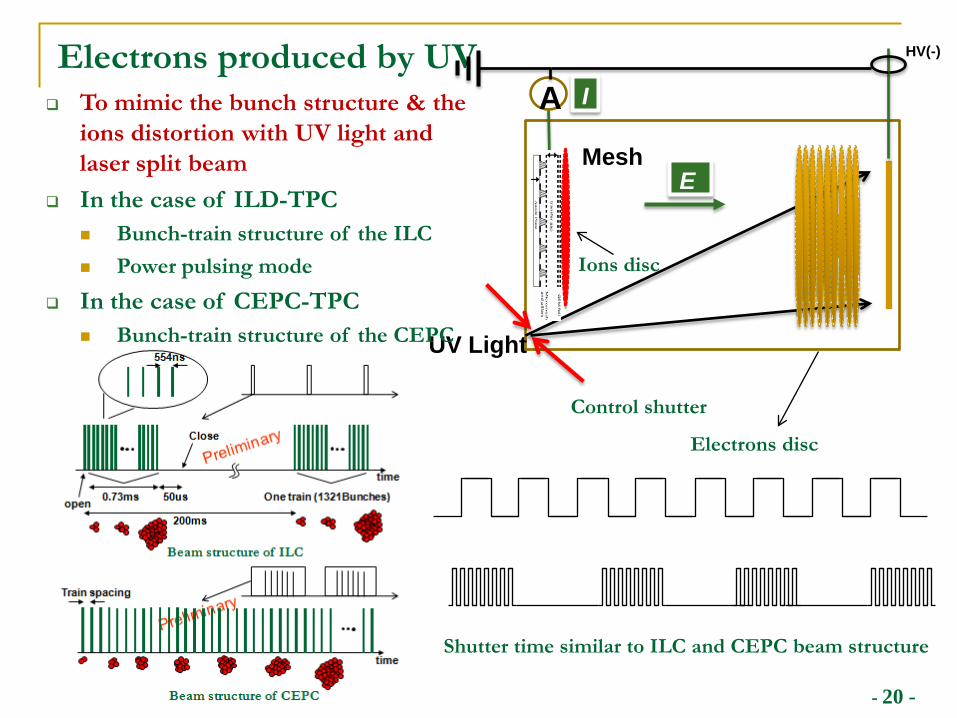
Electrons produced by UV HV(-)
Mesh
A
UV Light
E
I
Control shutter
To mimic the bunch structure & the ions distortion with UV light and laser split beam
In the case of ILD-TPC Bunch-train structure of the ILC Power pulsing mode
In the case of CEPC-TPC Bunch-train structure of the CEPC
Shutter time similar to ILC and CEPC beam structure
Electrons disc
Ions disc
- 21 -
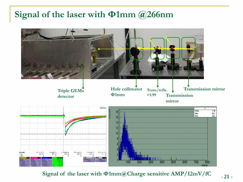
Signal of the laser with Ф1mm @266nm
Hole collimatorФ1mm
Trans/refle.=1:99 Transmission
mirror
Transmission mirror
Signal of the laser with Ф1mm@Charge sensitive AMP/12mV/fC
Triple GEMsdetector
- 22 -
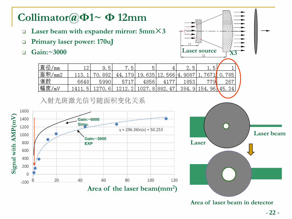
Collimator@Φ1~ Φ 12mm Laser beam with expander mirror: 5mm×3 Primary laser power: 170uJ Gain:~3000
Sign
al w
ith A
MP(
mV
)
Area of the laser beam(mm2)
Gain:~3000EXP
Gain:~5000Simu.
Area of laser beam in detector
LaserLaser beam
Laser source X3
- 23 -
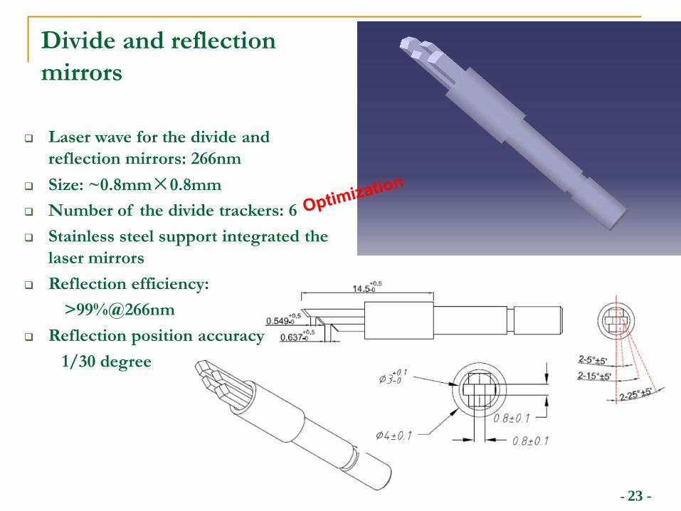
Divide and reflection mirrors
Laser wave for the divide and reflection mirrors: 266nm
Size: ~0.8mm×0.8mm Number of the divide trackers: 6 Stainless steel support integrated the
laser mirrors Reflection efficiency:
>99%@266nm Reflection position accuracy
1/30 degree
- 24 -
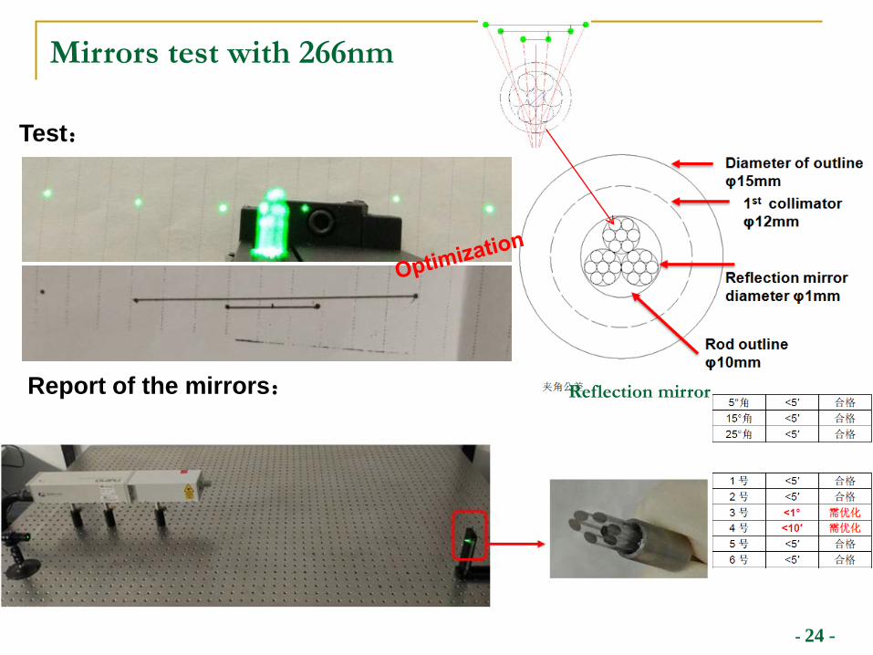
Test:
Report of the mirrors:
Mirrors test with 266nm
Reflection mirror
- 25 -
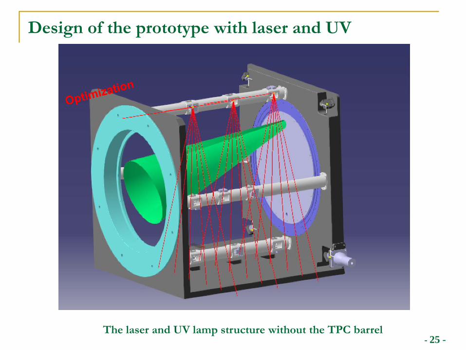
Design of the prototype with laser and UV
The laser and UV lamp structure without the TPC barrel
- 26 -
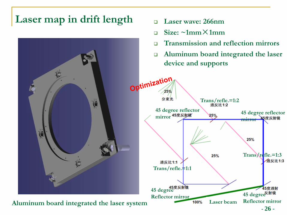
Laser map in drift length Laser wave: 266nm Size: ~1mm×1mm Transmission and reflection mirrors Aluminum board integrated the laser
device and supports
Aluminum board integrated the laser system
45 degree reflectormirror
45 degreeReflector mirror
45 degree reflectormirror
45 degreeReflector mirror
Laser beam
Trans/refle.=1:2
Trans/refle.=1:1
Trans/refle.=1:3
- 27 -
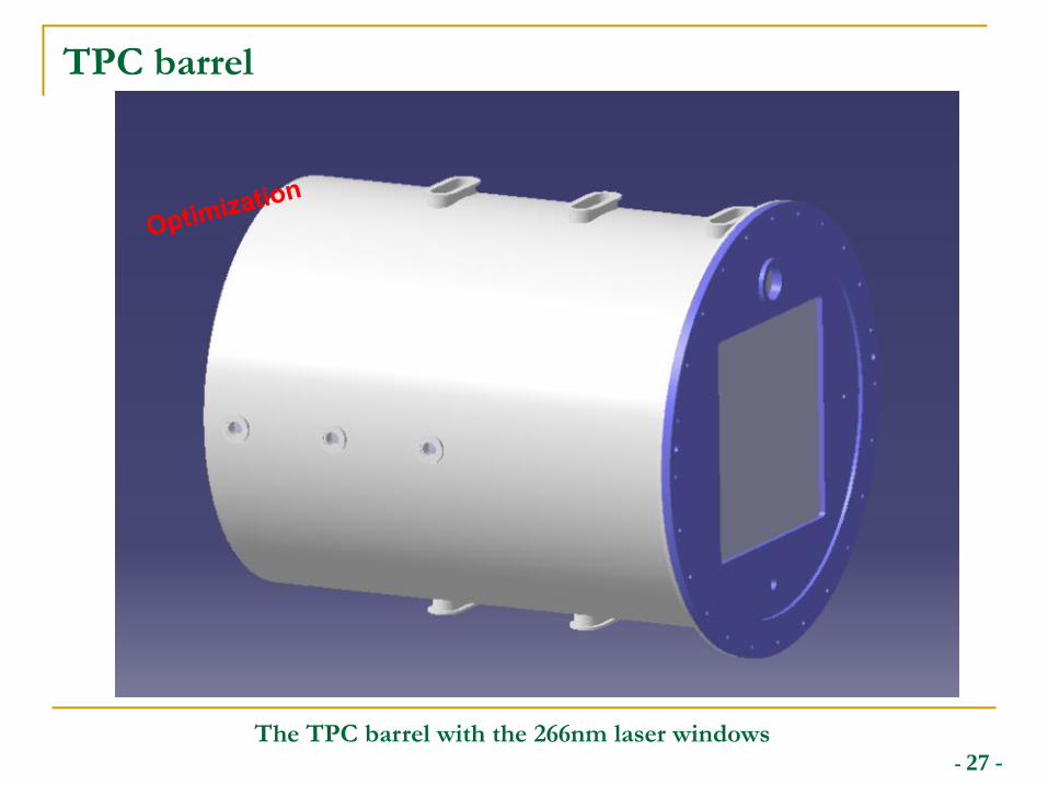
TPC barrel
The TPC barrel with the 266nm laser windows
- 28 -
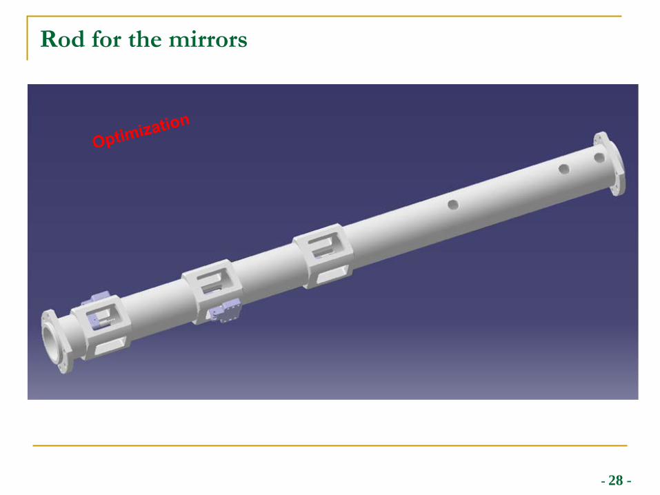
Rod for the mirrors
- 29 -
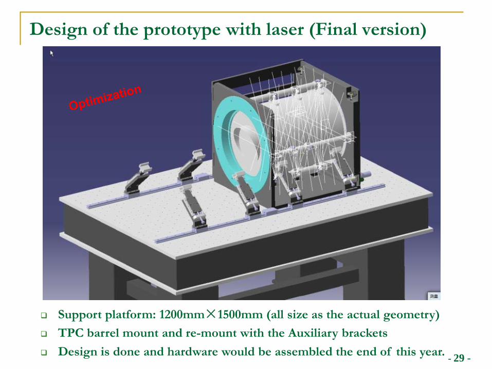
Design of the prototype with laser (Final version)
Support platform: 1200mm×1500mm (all size as the actual geometry) TPC barrel mount and re-mount with the Auxiliary brackets Design is done and hardware would be assembled the end of this year.
- 30 -
Summary
Physics requirements for the TPC modules Continuous Ion Back Flow due to the continuous beam structure Gating device could NOT be used due to the limit time Ion back flow is the most critical issue for the TPC module at
circular colliders
Some activities for the module and prototype IBF simulation of the detector have been started and further
simulated. Some preliminary IBF results of the continuous Ion Backflow
suppression detector modules has been analyzed. The design of the prototype integrated with UV and 266nm laser
has been done and assembled.
R&D work within some collaboration (LC-TPC/CEPC)

- 31 -
Thanks for your attention!