Embed Size (px)
Citation preview
1
The Steam Trap Design Group
Date: Dec. 19, 2008 Faculty: Dr. Sadegh ME473 Students:
Ivan Pinzon David Rodriguez
Syed Hasan Luis Molina
Massamaghan Kone
2
The Steam Trap Design Group Table Contents
NOMENCLATURE ........................................................................................................................................... 3
EXECUTIVE SUMMARY .................................................................................................................................. 5
INTRODUCTION ............................................................................................................................................. 7
PROBLEM STATEMENT .................................................................................................................................. 9
Gantt Chart ................................................................................................................................................. 16
Design Concept ........................................................................................................................................... 17
ANALYSIS ..................................................................................................................................................... 30
Heat transfer ............................................................................................................................................... 43
Energy Balance method for modeling the upward movement of a thermodynamic steam trap disc. ...... 45
NEW TECHNOLOGIES .................................................................................................................................. 48
CONCLUSION ............................................................................................................................................... 54
REFERENCES ................................................................................................................................................ 55
3
NOMENCLATURE Name Abbreviation Units
Sustained Stress Expansion Stress Allowable stress
Internal Design Pressure Outer Pipe Diameter
Inner Pipe Diameter Thickness
Stress Intensification
Resultant Moment Stress Reduction Factor
Section Modulus Volumetric Flow Rate
Velocity Area with respect to outer and
inner diameter
Mass Flow Rate Hydraulic Diameter Reynolds Number
Kinematics Viscosity Friction Factor
Saturated Fluid Density Length of Pipe
Pressure Drop Head Loss due to fittings, valve
and other components
Head Loss due to friction Total Head Loss
Resistance Coefficient
Gravitational Acceleration Pressure Wave Velocity
Bulk Modulus Young’s Modulus Pressure due to water hammer
Maximum Pressure due to water hammer
Pressure increase due to valve closing
Maximum pressure increase to valve closing

4
Time requires valve to close
5
EXECUTIVE SUMMARY
On July 18, 2007, at the intersection of 41st and Lexington in Manhattan, New York, a
geyser of hot steam erupted for over 2 hours. The force from the steam shook the ground and
spewed mud and debris, thus creating a steam cloud over 1000 feet high. The blast made a
crater over 35 ft wide and 15 ft deep through the middle of the street. At first people did not
know what was the cause of the explosion but after careful examination it was determined to
be due to the water hammer effect. Excess condensate is routinely removed in stations called
steam trap assemblies. It was discovered that the devices that removed the condensate,
referred to as steam traps were severely clogged with debris and were not functioning
properly. As a result, the steam main at that intersection filled up with condensate, due to a
routine pressure change, a large steam bubble entered the region, and then imploded. The
surrounding condensate fills in the void faster than the speed of sound. The force generated
was greater than the pipe can withstand, thus allowing the steam to burst into the streets.
Our objective as mechanical engineering students at the City College of New York in
conjunction with Con Edison is to design a steam trap assembly. The three main objectives are:
to increase steam trap capacity, to prevent the steam trap from clogging, to apply a device that
remotely monitors the steam trap’s performance and that would alert Con Edison when the
traps are failing. During our design process, safety is our main concern given the circumstances.
Pressure and temperature analysis was the main concern when dealing with high pressure
water main systems. Factors such as stress analysis due to sustained and expansion loadings
6
and heat transfer through the pipes were all incorporated into the selection process. The
materials, sizing and flow rate capacity for the steam trap assembly are dependent on the
results of the analysis. Solid modeling software such as Solidworks and Cosmosworks were
utilized in simulation and comparison of analysis.
The last aspect of the project was to implement a device that would remotely monitor
the steam trap. Several new technologies were considered such as: acoustic sensors and
ultrasonic flowmeters. Due to the expensive costs of these devices, further analysis will be
need in order to incorporate them into the next phase of the project. For the following
semester, an actual model will be assembled and we will attempt to simulate the conditions of
the steam trap assembly during normal operations. Our goal is to test the device that we
eventually select to detect when the trap is not working properly or if it’s completely clogged in
order to provide a means of remote monitoring. Hopefully our research will be a useful tool
that can be applied to future additions to steam trap monitoring systems.
7
INTRODUCTION
Con Edison provides steam as a carrier of energy through 105 miles of piping systems in
New York, providing heat and energy clean and efficiently. Steam is known for its efficient
means of transferring heat. Steam is non-flammable and non-toxic thus making it safer when
compared to fuel oils. Con Edison has 3 plants that produce 50% of its steam through a process
called co-generation. During this process the steam leaves the boiler and then goes through
pipes into a turbine generator. The resulting spinning of the turbine blades produces electricity.
The remaining steam then goes into the steam system. This results in the elimination of 1.6
million tons of CO2 annually.
There are a number of factors that come into play in order to create conditions for an
explosion. The infrastructure under the streets is overcrowded, and the steam mains are
subject to water infiltration, if systems such water pipe or sewer leaks. The main consensus as
the cause of the explosion is a phenomena called water hammer effect. According to the ABS
report, “It is a phenomenon that can occur when cold water comes in contact with a hot steam
pipe, causing the steam inside to condense into liquid water, locally increasing the pressure,
causing the pipe to burst.” Other factors were also considered that contributed to this localized
pressure increase. Con Edison has designated areas along its main steam line that drain excess
condensate (water in liquid form) into stations called steam trap assemblies. The main
component that converts excess steam into condensate is called the steam trap. Steam traps
are automatic valves that selectively allows condensate to pass and traps steam and creates
8
conditions that converts it back into its liquid form. In the Con Edison steam piping steam the
condensate is drained into the sewer system and therefore having unnecessary steam in the
sewer system is unfavorable.
Upon investigation, the steam traps failed to remove the condensate on that day for
two reasons. First there was heavy runoff from 1.59 inches of rainfall in a 5 hour period. Cold
water on the surface cooling the steam in contact with the pipe created a significant amount of
condensate. The condensate fills the pipe at the lowest point, the steam bubble forms and the
rupture occurred in a rising pipe bend section. The steam trap assembly was unable to remove
the condensate due to lack of flow. It was discovered that the traps that were used on 41st and
Lexington were almost completely clogged. Upon removal it was discovered that the
substances in the clog were metallic substances that have collected over the years which have
reduced the flow of condensate unnoticeably and compromised the ability of the steam traps
to remove condensate. It was discovered that the manholes that morning were releasing
steam, which was a clue to what was happening. However there is no automatic system in
place to notify Con Edison when there is too much condensate in the steam mains. It is
important to keep safety first in investing in steam operations in order to avoid accidents such
as the one in midtown in 2007.
9
PROBLEM STATEMENT
Objectives
The main objective of this project is to re-engineer the steam trap system so that all the
causes of the explosion can be diminished or avoided entirely. The primary cause of the
explosion was clogging of the steam trap due to debris and sealant. The debris came from a
source of erosion of the pipes interior wall. The sealant was present because it leaked in after
previous maintenance work done on leaky pipes throughout the system. The combination of
the debris and sealant lead to the grave explosion, which occurred on July 18, 2007 at East 41st
Street and Lexington Avenue. The explosion happened because the traps were clogged, steam
and condensate began to build up, the steam bubble formed and burst, causing intense
shockwaves due to the water hammer effect.
The type of water hammer that occurred in the system was a condensation-induced
water hammer effect. This kind of water hammer occurs when steam collapses into condensate
creating a void thus causing the condensate to rush in to fill the void and smash into itself. This
then creates a pressure pulse that can reach magnitudes of 1,000 to 2,000 psig. This pulse then
traveled through the condensate at the speed of sound in a fluid, 4,000 ft/s, combined with the
internal loadings and stresses of the pipes it exceeded the material strength of the pipes and
the pipe ruptured. The objective here would be to find a way of preventing the steam traps
from getting clogged.
10
After determining a way of preventing the steam traps from getting clogged the next
objective would be to increase the capacity of the steam trap system. Now this is an open-
ended problem because there is more than one way of increasing the capacity of the steam
trap system. The trap itself can be re-designed to increase capacity or the system can be re-
designed so as to include more traps, thus increasing the capacity of the system. Our challenge
here is determining which method of increasing the capacity of the system is the most efficient,
cost-effective, and works best with our constraints.
The next objective of the project was to develop a remote monitoring system. Con
Edison wants to develop a system that will allow them to monitor the steam trap system from
their plant. The problem here is the extreme conditions within the manhole chamber in which
the steam trap system is located are not ideal for sensors. The temperature in the chamber is
212°F and there is a high oxidation rate, there are very limited sensors that would survive in
that kind of environment. Placing sensors within the piping system itself is a problem as well
because of pipe erosion, high temperature, and once again oxidation. The challenge here is to
try and find a technology that can determine whether or not the steam traps are working
properly as well as withstand the extreme conditions of the steam trap chamber.
Another objective of the project is to calculate internal pressures and stresses at key
points in the steam trap system. For this a thorough understanding of fluid dynamics, stress,
and heat transfer analysis in pipes is needed. The formulas needed to carry out these
calculations were obtained from a number of mechanical engineering handbooks. The results of
this objective will be compared with the results of FEM analysis that will be done using
11
SolidWorks, CosmosWorks, FlowWorks, and ANSYS. This objective will be the most time
consuming due to errors in calculations, and determining how to setup the correct boundary
conditions for the analysis.
The next objective would be material selection. This is a very important aspect of the
project because of the environment of the steam trap chamber. Not all materials would be able
to survive under those extreme conditions. In addition to the life span of materials we would
need to select materials that would be able to sustain the pressures and stresses obtained from
the calculations of stresses and pressures. Steel and Iron pipes are not a good fit because of
oxidation; these systems are intended to last many years and using pipes made from these
materials would require frequent maintenance of the system. The challenge here is to be able
to determine which materials will be able to sustain the loads, pressures, and stresses as well as
resist erosion and oxidation.
Specifications
There were certain specifications and constraints given for this project. One was size
constraint. The chamber of the manhole has a measurement of 4 ft tall by 3 ft wide by 2 ft
deep. This constraint was essential in our designs because it restricted the variation of the
assembly of the system. Another constraint that applied to the manhole chamber is that all the
valves must be installed with the knobs facing upward at a 45° angle. This allows for Con Edison
maintenance workers to easily access the valves from the street using a special apparatus.
Specifications of the inlet parameters were given to us as well. The inlet pressure of the
system is 180 psig. The inlet temperature is 381° F and the mass flow rate at the inlet header is
12
2300 lbm/hr. The ambient temperature of the chamber is in the range of 212-250° F. These
specifications were important in our hand calculations for fluid dynamics, stress analysis, and
heat transfer analysis. The calculations and specifications were instrumental in the selection of
material.
Steps Taken
The proposition of strainers was the solution to trap clogging. Strainers come in all
shape and sizes. A strainers job is to act as a filter in a pipeline; it contains a cylindrical screen
that traps foreign particles in the fluid. The size of the holes in the screen determines the size of
the particles that are allowed through. Some steam traps come with a strainer already
implemented in it, it is something that we are considering.
In order to increase the capacity of the steam trap system from 4600 lbm/hr to 8000
lbm/hr there were two methods that can be employed. The first method would be to increase
the capacity of each steam trap itself. This is the more difficult and time consuming (in terms of
design) of the two methods. Increasing the capacity of the trap would allow a greater flow rate
through it but many aspects must be taken into account when doing this. The most important
aspect is the backpressure of the system. If not designed correctly the trap may be caused to
fail and depending on the backpressure it could fail open, which would be good in terms of
safety, or it could fail closed, which would lead to the same outcome as if the trap were
clogged. The second method would be to increase the number of lines with steam traps. This
would allow us to use a larger quantity of the same steam traps that are already in use in the
system. The flow rate that goes through the system can be increased by the capacity of each
trap. This method is more feasible and can be implemented into designs with more ease.
13
The solution to remote monitoring of the system has not yet been determined. We have
looked into a number of sensors and technologies trying to determine which would be best
suited for our system. Once again the problem here are the extreme conditions of the chamber
of the manhole as well as inside the pipes, not many sensors would survive very long under
these conditions. We have found some technologies that offer potential but most would be too
expensive to purchase for this purpose. We intend to continue to look at the technologies with
potential as well as try and find some others. The solution that Con Edison suggested was the
use of two thermal couples per steam trap. This would allow them to monitor the temperature
of the pipe as the fluid comes out of the trap, if the temperature is fluctuating between
ambient temperature and the temperature of the fluid then the trap is working, if the
temperature stays constant (such as reading the ambient temperature) that means the trap is
not working. This solution works but it also adds length to the assembly, which is not good in
regards to our space constraint.
The calculation of stresses inside the pipes took some time in terms of investigating the
correct formulas to use as well as getting reasonable numbers from our calculations. The
calculations included two-phase fluid dynamics in a pipe; stress analysis due to static loading,
internal pressures, and thermal expansion; and heat transfer analysis on the system
(Conduction through pipes and Convection with Ambient Air). The material for the system was
given to us by Con Edison to be red brass for the pipes, bronze for the valves, and steel for the
strainers and steam traps. The solid modeling for the project was done using SolidWorks, while

14
the analysis was tried in ANSYS but to no luck. None of the group members were able to master
the program in time to get the results, so FlowWorks and CosmosWorks were used instead.

15
16
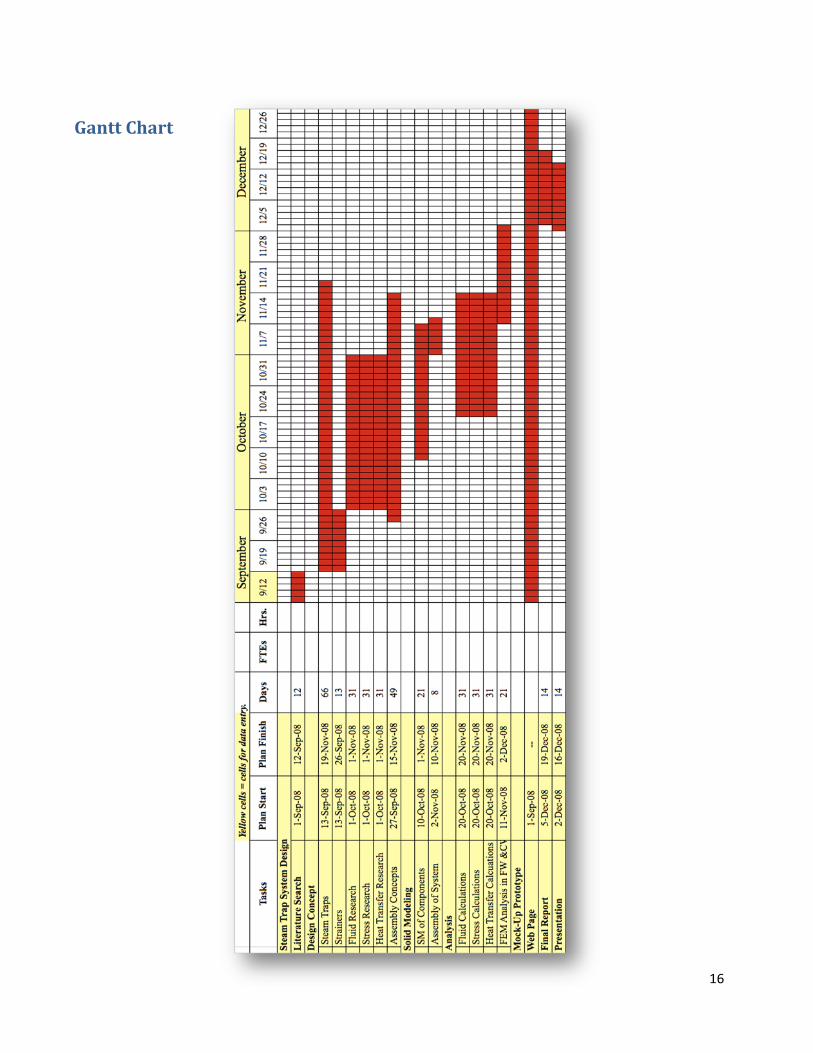
Gantt Chart
17
Design Concept
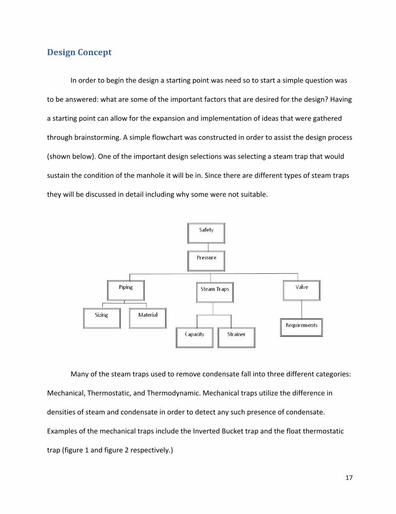
In order to begin the design a starting point was need so to start a simple question was
to be answered: what are some of the important factors that are desired for the design? Having
a starting point can allow for the expansion and implementation of ideas that were gathered
through brainstorming. A simple flowchart was constructed in order to assist the design process
(shown below). One of the important design selections was selecting a steam trap that would
sustain the condition of the manhole it will be in. Since there are different types of steam traps
they will be discussed in detail including why some were not suitable.
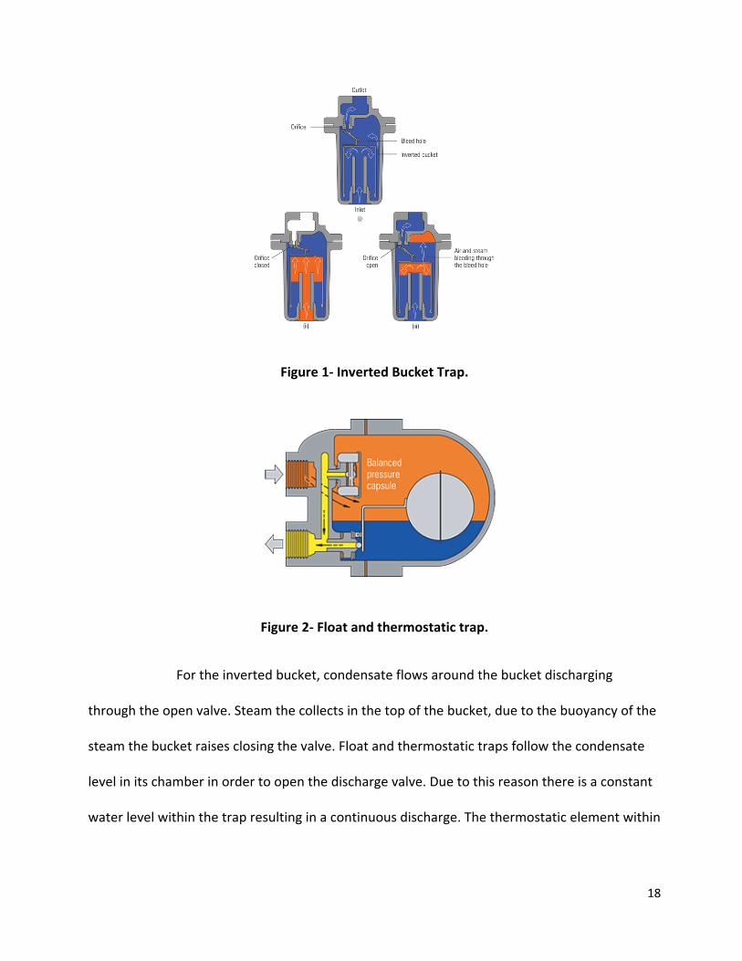
Many of the steam traps used to remove condensate fall into three different categories:
Mechanical, Thermostatic, and Thermodynamic. Mechanical traps utilize the difference in
densities of steam and condensate in order to detect any such presence of condensate.
Examples of the mechanical traps include the Inverted Bucket trap and the float thermostatic
trap (figure 1 and figure 2 respectively.)
18
Figure 1- Inverted Bucket Trap.
Figure 2- Float and thermostatic trap.
For the inverted bucket, condensate flows around the bucket discharging
through the open valve. Steam the collects in the top of the bucket, due to the buoyancy of the
steam the bucket raises closing the valve. Float and thermostatic traps follow the condensate
level in its chamber in order to open the discharge valve. Due to this reason there is a constant
water level within the trap resulting in a continuous discharge. The thermostatic element within
19
the trap purges air and other gases at temperatures lower than saturation temperature of the
steam.
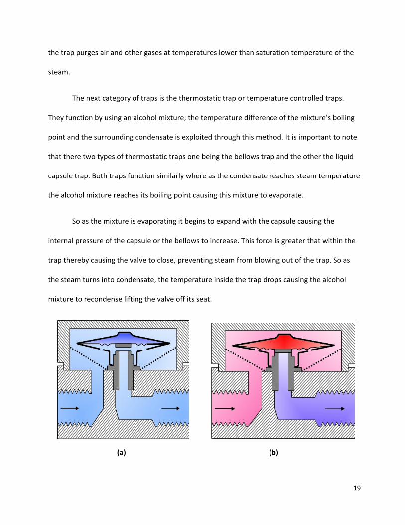
The next category of traps is the thermostatic trap or temperature controlled traps.
They function by using an alcohol mixture; the temperature difference of the mixture’s boiling
point and the surrounding condensate is exploited through this method. It is important to note
that there two types of thermostatic traps one being the bellows trap and the other the liquid
capsule trap. Both traps function similarly where as the condensate reaches steam temperature
the alcohol mixture reaches its boiling point causing this mixture to evaporate.
So as the mixture is evaporating it begins to expand with the capsule causing the
internal pressure of the capsule or the bellows to increase. This force is greater that within the
trap thereby causing the valve to close, preventing steam from blowing out of the trap. So as
the steam turns into condensate, the temperature inside the trap drops causing the alcohol
mixture to recondense lifting the valve off its seat.
(a) (b)
20
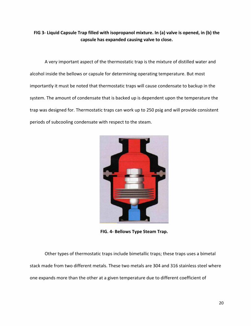
FIG 3- Liquid Capsule Trap filled with isopropanol mixture. In (a) valve is opened, in (b) the capsule has expanded causing valve to close.
A very important aspect of the thermostatic trap is the mixture of distilled water and
alcohol inside the bellows or capsule for determining operating temperature. But most
importantly it must be noted that thermostatic traps will cause condensate to backup in the
system. The amount of condensate that is backed up is dependent upon the temperature the
trap was designed for. Thermostatic traps can work up to 250 psig and will provide consistent
periods of subcooling condensate with respect to the steam.
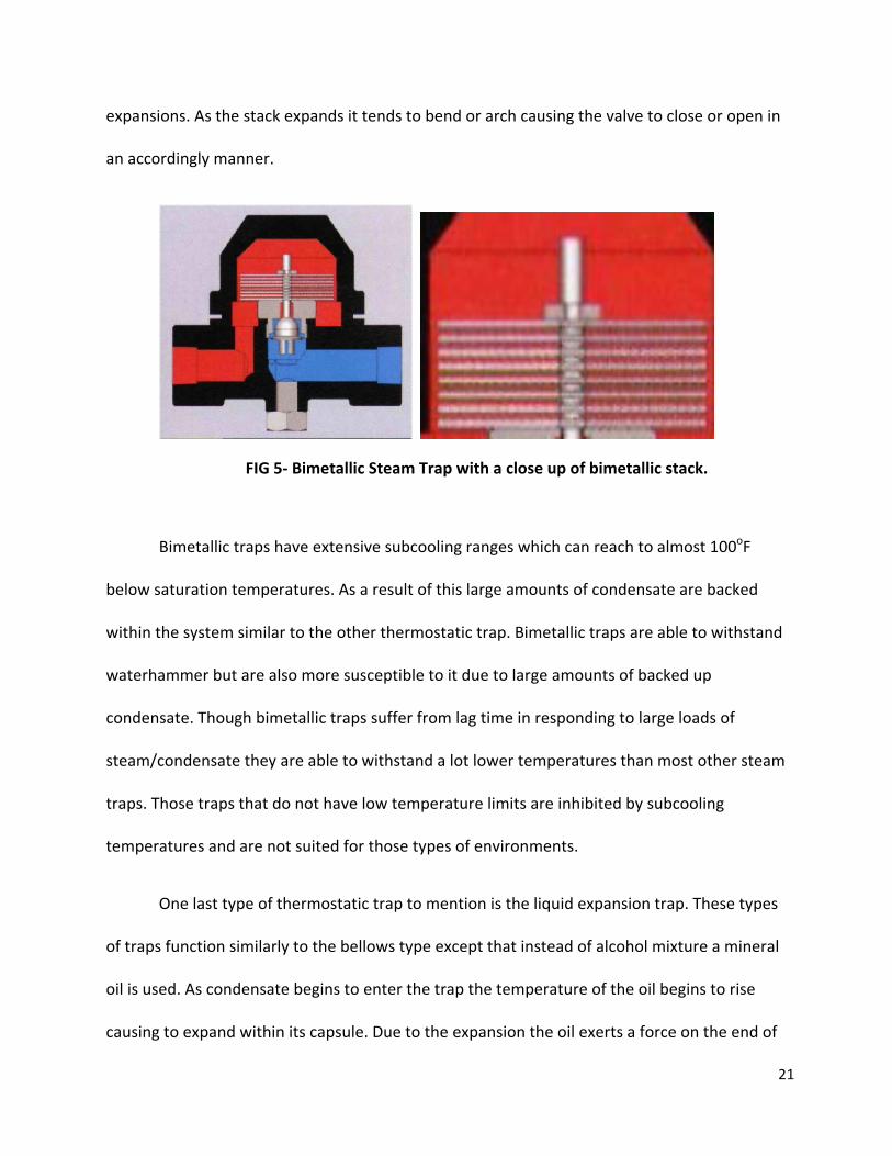
FIG. 4- Bellows Type Steam Trap.
Other types of thermostatic traps include bimetallic traps; these traps uses a bimetal
stack made from two different metals. These two metals are 304 and 316 stainless steel where
one expands more than the other at a given temperature due to different coefficient of
21
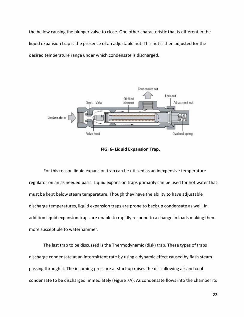
expansions. As the stack expands it tends to bend or arch causing the valve to close or open in
an accordingly manner.
FIG 5- Bimetallic Steam Trap with a close up of bimetallic stack.
Bimetallic traps have extensive subcooling ranges which can reach to almost 100oF
below saturation temperatures. As a result of this large amounts of condensate are backed
within the system similar to the other thermostatic trap. Bimetallic traps are able to withstand
waterhammer but are also more susceptible to it due to large amounts of backed up
condensate. Though bimetallic traps suffer from lag time in responding to large loads of
steam/condensate they are able to withstand a lot lower temperatures than most other steam
traps. Those traps that do not have low temperature limits are inhibited by subcooling
temperatures and are not suited for those types of environments.
One last type of thermostatic trap to mention is the liquid expansion trap. These types
of traps function similarly to the bellows type except that instead of alcohol mixture a mineral
oil is used. As condensate begins to enter the trap the temperature of the oil begins to rise
causing to expand within its capsule. Due to the expansion the oil exerts a force on the end of
22
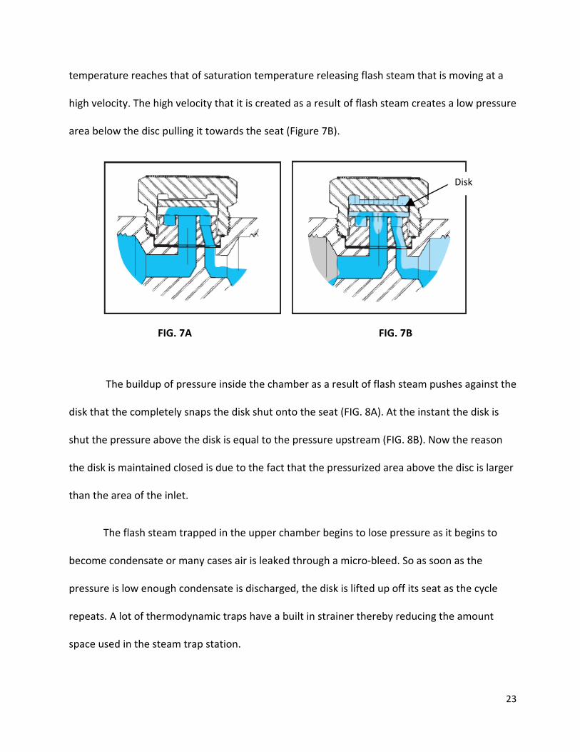
the bellow causing the plunger valve to close. One other characteristic that is different in the
liquid expansion trap is the presence of an adjustable nut. This nut is then adjusted for the
desired temperature range under which condensate is discharged.
FIG. 6- Liquid Expansion Trap.
For this reason liquid expansion trap can be utilized as an inexpensive temperature
regulator on an as needed basis. Liquid expansion traps primarily can be used for hot water that
must be kept below steam temperature. Though they have the ability to have adjustable
discharge temperatures, liquid expansion traps are prone to back up condensate as well. In
addition liquid expansion traps are unable to rapidly respond to a change in loads making them
more susceptible to waterhammer.
The last trap to be discussed is the Thermodynamic (disk) trap. These types of traps
discharge condensate at an intermittent rate by using a dynamic effect caused by flash steam
passing through it. The incoming pressure at start-up raises the disc allowing air and cool
condensate to be discharged immediately (Figure 7A). As condensate flows into the chamber its
23
temperature reaches that of saturation temperature releasing flash steam that is moving at a
high velocity. The high velocity that it is created as a result of flash steam creates a low pressure
area below the disc pulling it towards the seat (Figure 7B).
FIG. 7A FIG. 7B
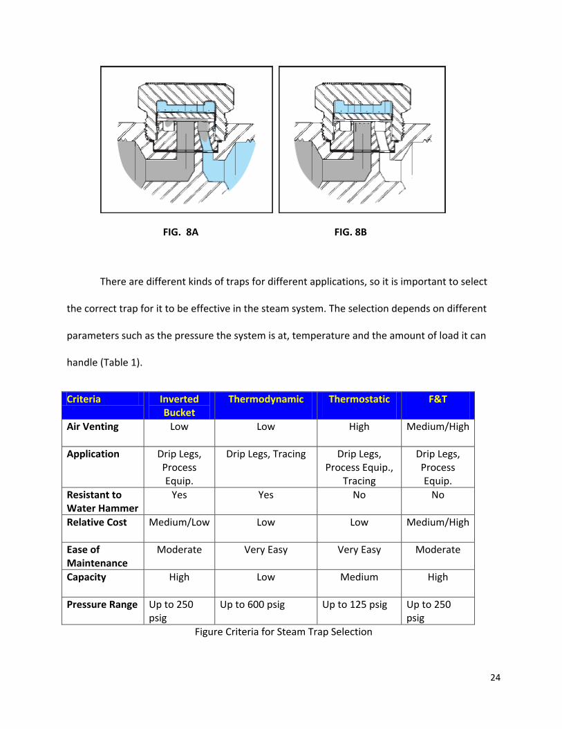
The buildup of pressure inside the chamber as a result of flash steam pushes against the
disk that the completely snaps the disk shut onto the seat (FIG. 8A). At the instant the disk is
shut the pressure above the disk is equal to the pressure upstream (FIG. 8B). Now the reason
the disk is maintained closed is due to the fact that the pressurized area above the disc is larger
than the area of the inlet.
The flash steam trapped in the upper chamber begins to lose pressure as it begins to
become condensate or many cases air is leaked through a micro-bleed. So as soon as the
pressure is low enough condensate is discharged, the disk is lifted up off its seat as the cycle
repeats. A lot of thermodynamic traps have a built in strainer thereby reducing the amount
space used in the steam trap station.
Disk
24
FIG. 8A FIG. 8B
There are different kinds of traps for different applications, so it is important to select
the correct trap for it to be effective in the steam system. The selection depends on different
parameters such as the pressure the system is at, temperature and the amount of load it can
handle (Table 1).
Criteria Inverted Bucket
Thermodynamic Thermostatic F&T
Air Venting Low Low High Medium/High
Application Drip Legs, Process Equip.
Drip Legs, Tracing Drip Legs, Process Equip.,
Tracing
Drip Legs, Process Equip.
Resistant to Water Hammer
Yes Yes No No
Relative Cost Medium/Low Low Low Medium/High
Ease of Maintenance
Moderate Very Easy Very Easy Moderate
Capacity High Low Medium High
Pressure Range Up to 250 psig
Up to 600 psig Up to 125 psig Up to 250 psig
Figure Criteria for Steam Trap Selection
25
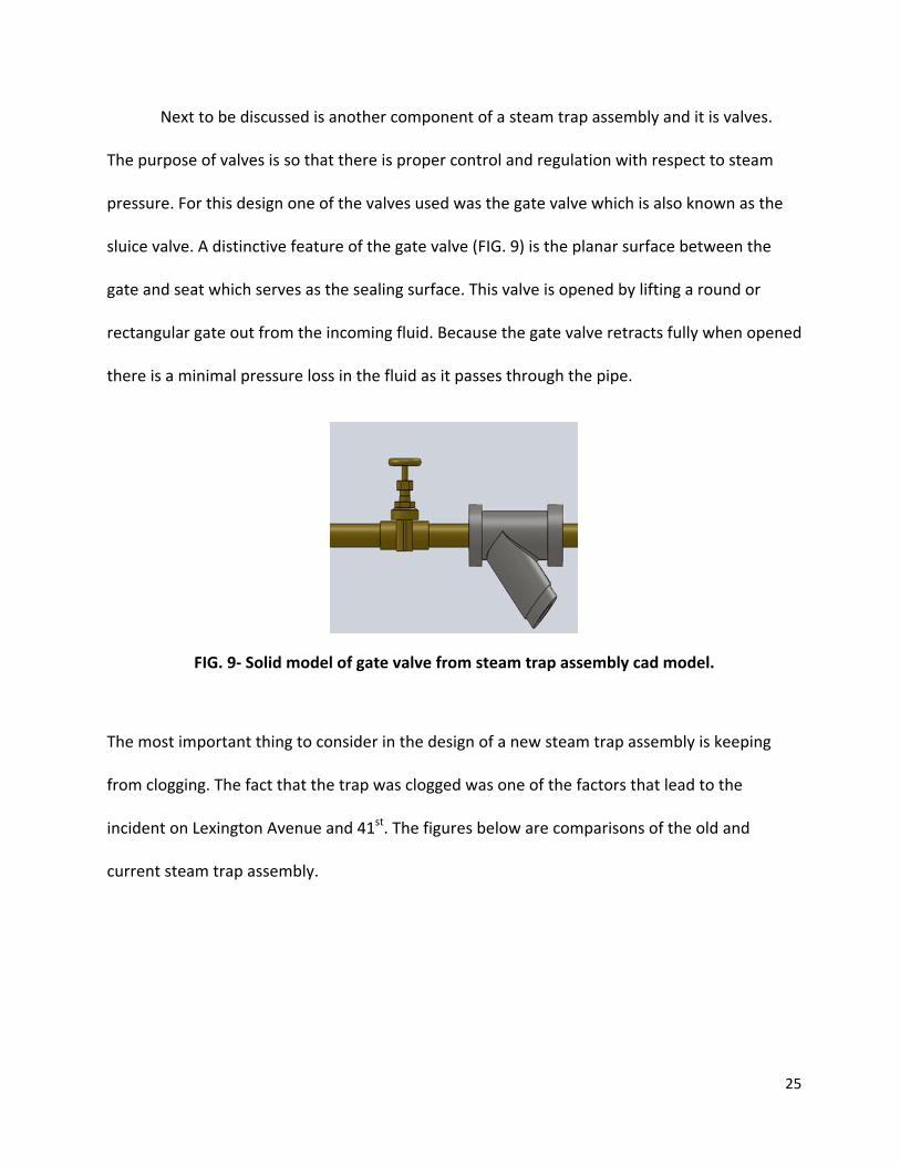
Next to be discussed is another component of a steam trap assembly and it is valves.
The purpose of valves is so that there is proper control and regulation with respect to steam
pressure. For this design one of the valves used was the gate valve which is also known as the
sluice valve. A distinctive feature of the gate valve (FIG. 9) is the planar surface between the
gate and seat which serves as the sealing surface. This valve is opened by lifting a round or
rectangular gate out from the incoming fluid. Because the gate valve retracts fully when opened
there is a minimal pressure loss in the fluid as it passes through the pipe.
FIG. 9- Solid model of gate valve from steam trap assembly cad model.
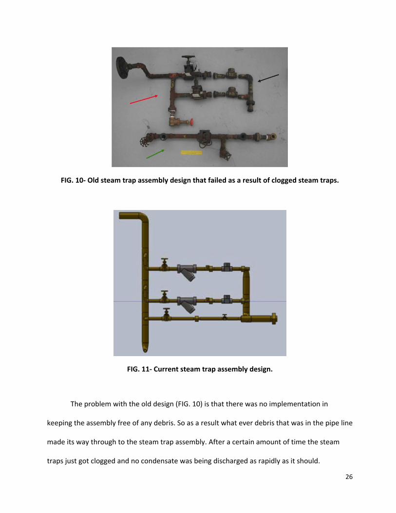
The most important thing to consider in the design of a new steam trap assembly is keeping
from clogging. The fact that the trap was clogged was one of the factors that lead to the
incident on Lexington Avenue and 41st. The figures below are comparisons of the old and
current steam trap assembly.
26
FIG. 10- Old steam trap assembly design that failed as a result of clogged steam traps.
FIG. 11- Current steam trap assembly design.
The problem with the old design (FIG. 10) is that there was no implementation in
keeping the assembly free of any debris. So as a result what ever debris that was in the pipe line
made its way through to the steam trap assembly. After a certain amount of time the steam
traps just got clogged and no condensate was being discharged as rapidly as it should.
27
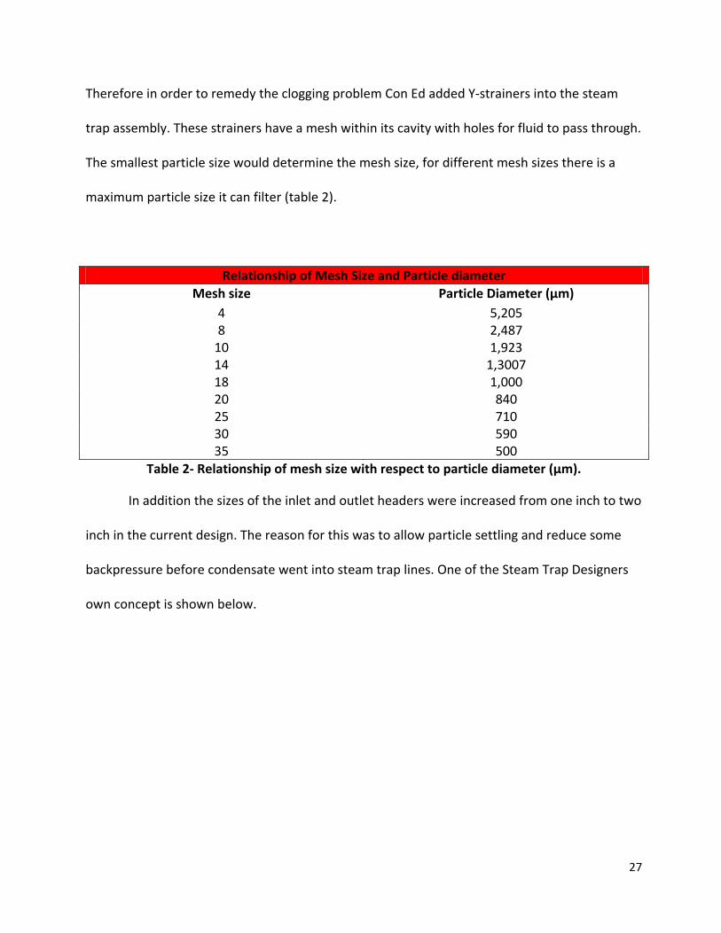
Therefore in order to remedy the clogging problem Con Ed added Y-strainers into the steam
trap assembly. These strainers have a mesh within its cavity with holes for fluid to pass through.
The smallest particle size would determine the mesh size, for different mesh sizes there is a
maximum particle size it can filter (table 2).
Relationship of Mesh Size and Particle diameter Mesh size Particle Diameter (μm)
4 5,205 8 2,487
10 1,923 14 1,3007 18 1,000 20 840 25 710 30 590 35 500
Table 2- Relationship of mesh size with respect to particle diameter (μm).
In addition the sizes of the inlet and outlet headers were increased from one inch to two
inch in the current design. The reason for this was to allow particle settling and reduce some
backpressure before condensate went into steam trap lines. One of the Steam Trap Designers
own concept is shown below.
28
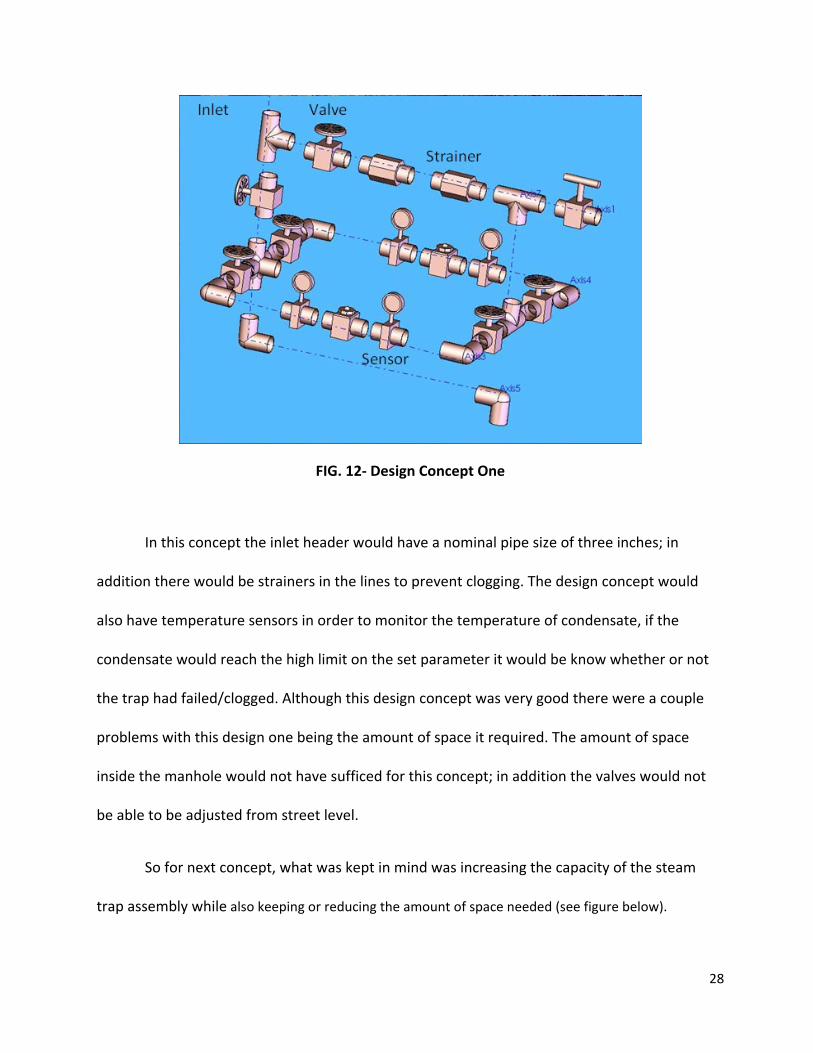
FIG. 12- Design Concept One
In this concept the inlet header would have a nominal pipe size of three inches; in
addition there would be strainers in the lines to prevent clogging. The design concept would
also have temperature sensors in order to monitor the temperature of condensate, if the
condensate would reach the high limit on the set parameter it would be know whether or not
the trap had failed/clogged. Although this design concept was very good there were a couple
problems with this design one being the amount of space it required. The amount of space
inside the manhole would not have sufficed for this concept; in addition the valves would not
be able to be adjusted from street level.
So for next concept, what was kept in mind was increasing the capacity of the steam
trap assembly while also keeping or reducing the amount of space needed (see figure below).
29
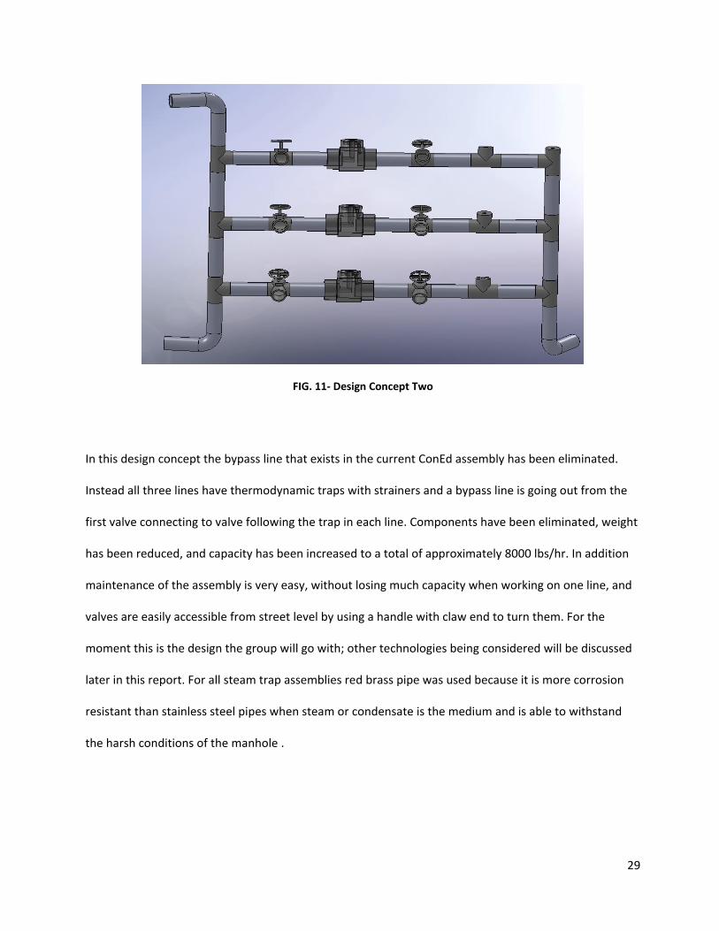
FIG. 11- Design Concept Two
In this design concept the bypass line that exists in the current ConEd assembly has been eliminated.
Instead all three lines have thermodynamic traps with strainers and a bypass line is going out from the
first valve connecting to valve following the trap in each line. Components have been eliminated, weight
has been reduced, and capacity has been increased to a total of approximately 8000 lbs/hr. In addition
maintenance of the assembly is very easy, without losing much capacity when working on one line, and
valves are easily accessible from street level by using a handle with claw end to turn them. For the
moment this is the design the group will go with; other technologies being considered will be discussed
later in this report. For all steam trap assemblies red brass pipe was used because it is more corrosion
resistant than stainless steel pipes when steam or condensate is the medium and is able to withstand
the harsh conditions of the manhole .
30
ANALYSIS
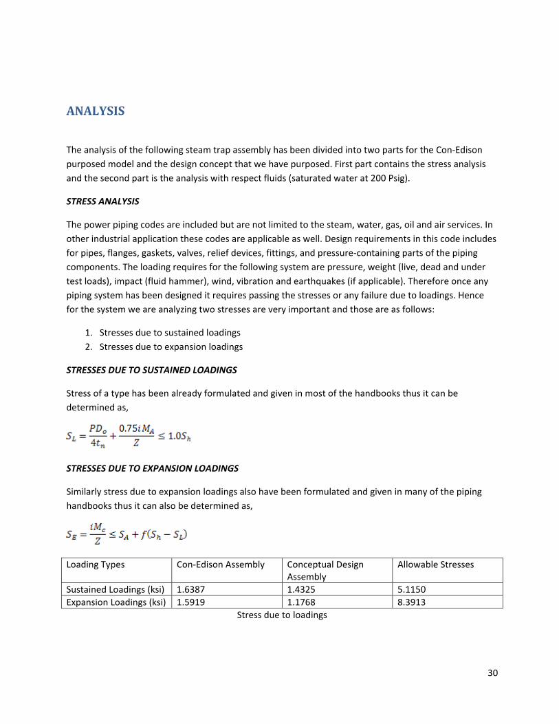
The analysis of the following steam trap assembly has been divided into two parts for the Con-Edison purposed model and the design concept that we have purposed. First part contains the stress analysis and the second part is the analysis with respect fluids (saturated water at 200 Psig).
STRESS ANALYSIS
The power piping codes are included but are not limited to the steam, water, gas, oil and air services. In other industrial application these codes are applicable as well. Design requirements in this code includes for pipes, flanges, gaskets, valves, relief devices, fittings, and pressure-containing parts of the piping components. The loading requires for the following system are pressure, weight (live, dead and under test loads), impact (fluid hammer), wind, vibration and earthquakes (if applicable). Therefore once any piping system has been designed it requires passing the stresses or any failure due to loadings. Hence for the system we are analyzing two stresses are very important and those are as follows:
1. Stresses due to sustained loadings 2. Stresses due to expansion loadings
STRESSES DUE TO SUSTAINED LOADINGS
Stress of a type has been already formulated and given in most of the handbooks thus it can be determined as,
STRESSES DUE TO EXPANSION LOADINGS
Similarly stress due to expansion loadings also have been formulated and given in many of the piping handbooks thus it can also be determined as,
Loading Types Con-Edison Assembly Conceptual Design Assembly
Allowable Stresses
Sustained Loadings (ksi) 1.6387 1.4325 5.1150 Expansion Loadings (ksi) 1.5919 1.1768 8.3913
Stress due to loadings

31
FLUID ANALYSIS
The fluid analysis for the particular type of structure or assembly is not easy and cannot be done in one shot. Thus it may required series of calculation and might require iterating the problems in determining the desire unknown values. With respect to the fluid flow in any piping system there are three important concepts always required to keep in mind. Those concepts are as follows:
1. PRESSURE DROP- The drop in pressure caused by viscous effects during the fluid flow through the pipes or ducts.
2. HEAD LOSS-A pressure loss of fluid in terms of fluid height either due to friction or change in velocity. The head loss can be major that will be due to the friction and minor due to the valve or any other fitting or components.
3. BACK PRESSURE-A pressure that is created by water hammer due to the sudden stoppage of flow when a valve or closing component (Thermodynamic steam traps) closes rapidly. Such type of a pressure also called HAMMER PRESSURE.
FROM POINT-1 TO POINT-2
Fluid flow from point-1 to point-2
VELOCITY DETERMINATION
Since the mass flow rate is known thus the entrance velocity in the header and the velocity at 1st horizontal pipe can be determined. Thus the velocities can be calculated as
The volumetric flow rate then can be determined as,
1
2
32
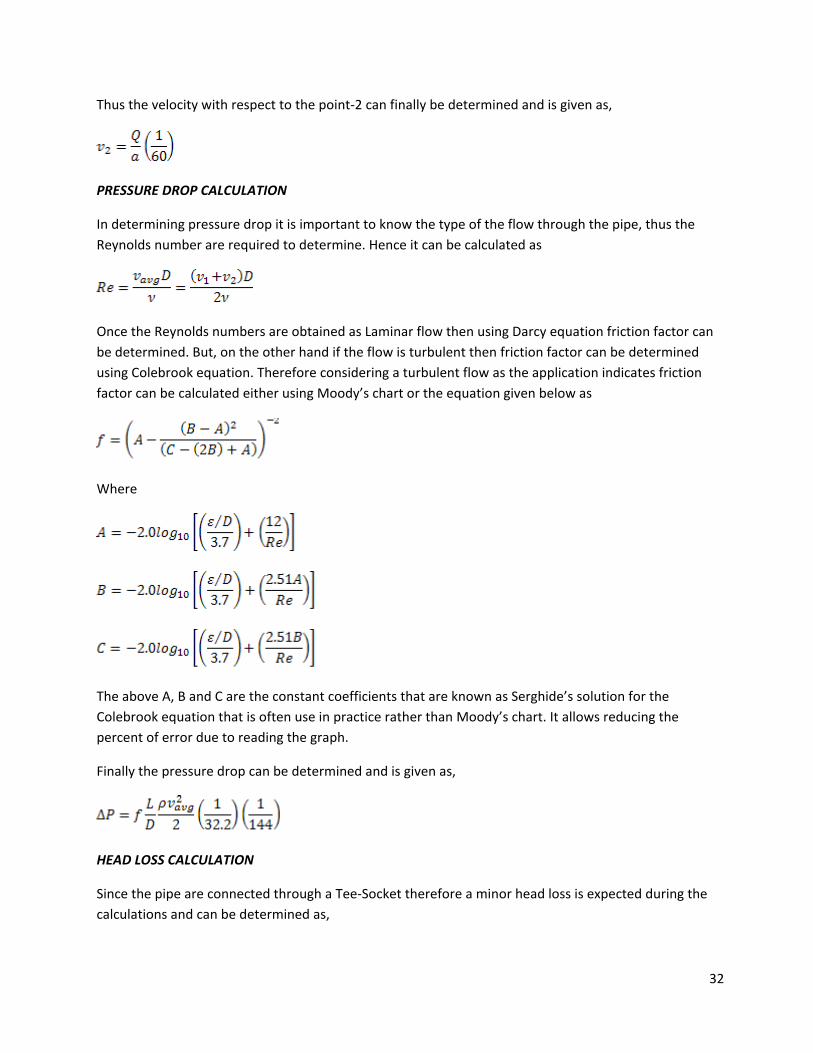
Thus the velocity with respect to the point-2 can finally be determined and is given as,
PRESSURE DROP CALCULATION
In determining pressure drop it is important to know the type of the flow through the pipe, thus the Reynolds number are required to determine. Hence it can be calculated as
Once the Reynolds numbers are obtained as Laminar flow then using Darcy equation friction factor can be determined. But, on the other hand if the flow is turbulent then friction factor can be determined using Colebrook equation. Therefore considering a turbulent flow as the application indicates friction factor can be calculated either using Moody’s chart or the equation given below as
Where
The above A, B and C are the constant coefficients that are known as Serghide’s solution for the Colebrook equation that is often use in practice rather than Moody’s chart. It allows reducing the percent of error due to reading the graph.
Finally the pressure drop can be determined and is given as,
HEAD LOSS CALCULATION
Since the pipe are connected through a Tee-Socket therefore a minor head loss is expected during the calculations and can be determined as,
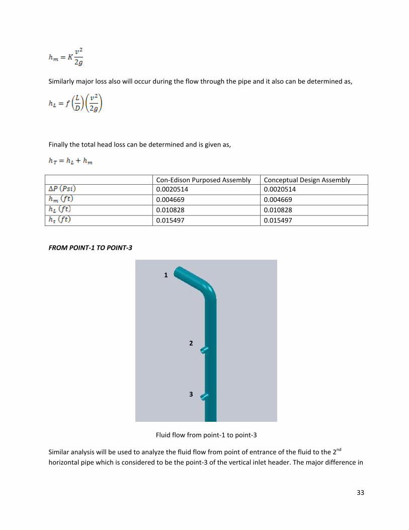
33
Similarly major loss also will occur during the flow through the pipe and it also can be determined as,
Finally the total head loss can be determined and is given as,
Con-Edison Purposed Assembly Conceptual Design Assembly
0.0020514 0.0020514
0.004669 0.004669
0.010828 0.010828
0.015497 0.015497
FROM POINT-1 TO POINT-3
Fluid flow from point-1 to point-3
Similar analysis will be used to analyze the fluid flow from point of entrance of the fluid to the 2nd horizontal pipe which is considered to be the point-3 of the vertical inlet header. The major difference in
1
2
3
34
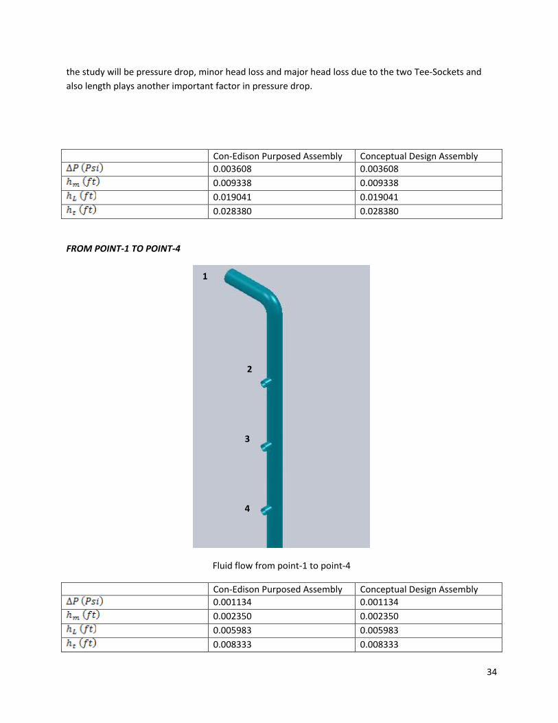
the study will be pressure drop, minor head loss and major head loss due to the two Tee-Sockets and also length plays another important factor in pressure drop.
Con-Edison Purposed Assembly Conceptual Design Assembly
0.003608 0.003608
0.009338 0.009338
0.019041 0.019041
0.028380 0.028380
FROM POINT-1 TO POINT-4
Fluid flow from point-1 to point-4
Con-Edison Purposed Assembly Conceptual Design Assembly
0.001134 0.001134
0.002350 0.002350
0.005983 0.005983
0.008333 0.008333
1
2
3
4
35
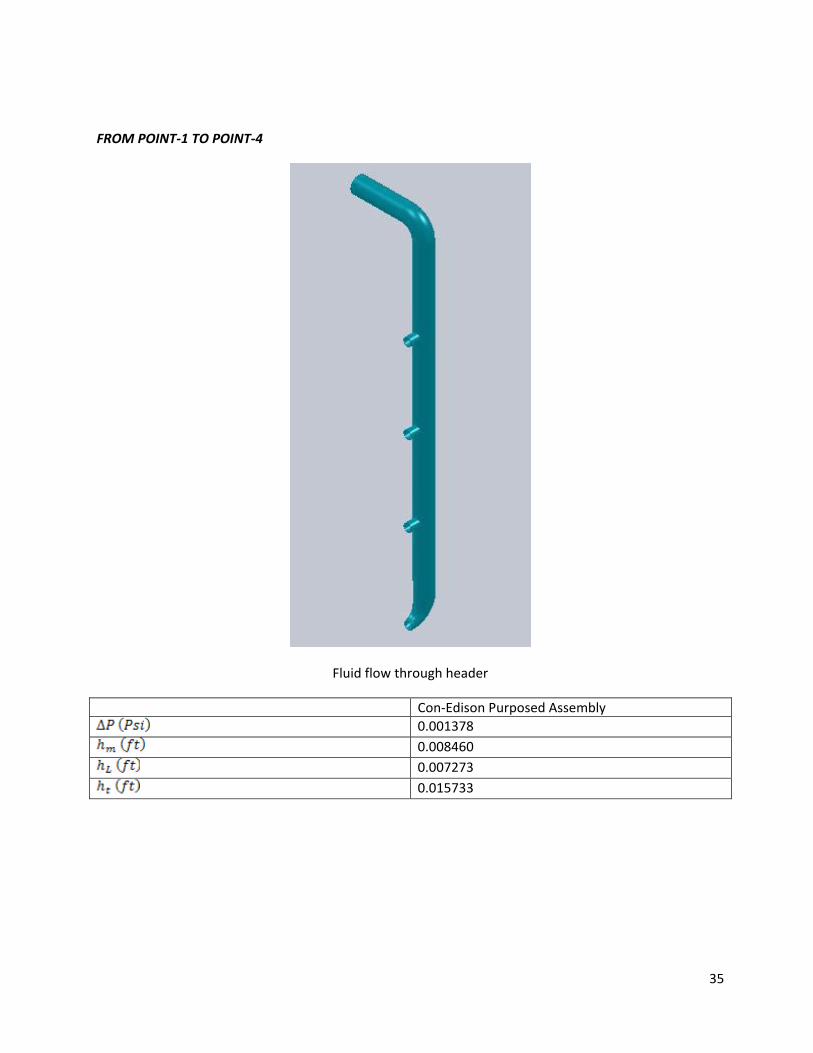
FROM POINT-1 TO POINT-4
Fluid flow through header
Con-Edison Purposed Assembly
0.001378
0.008460
0.007273
0.015733
36
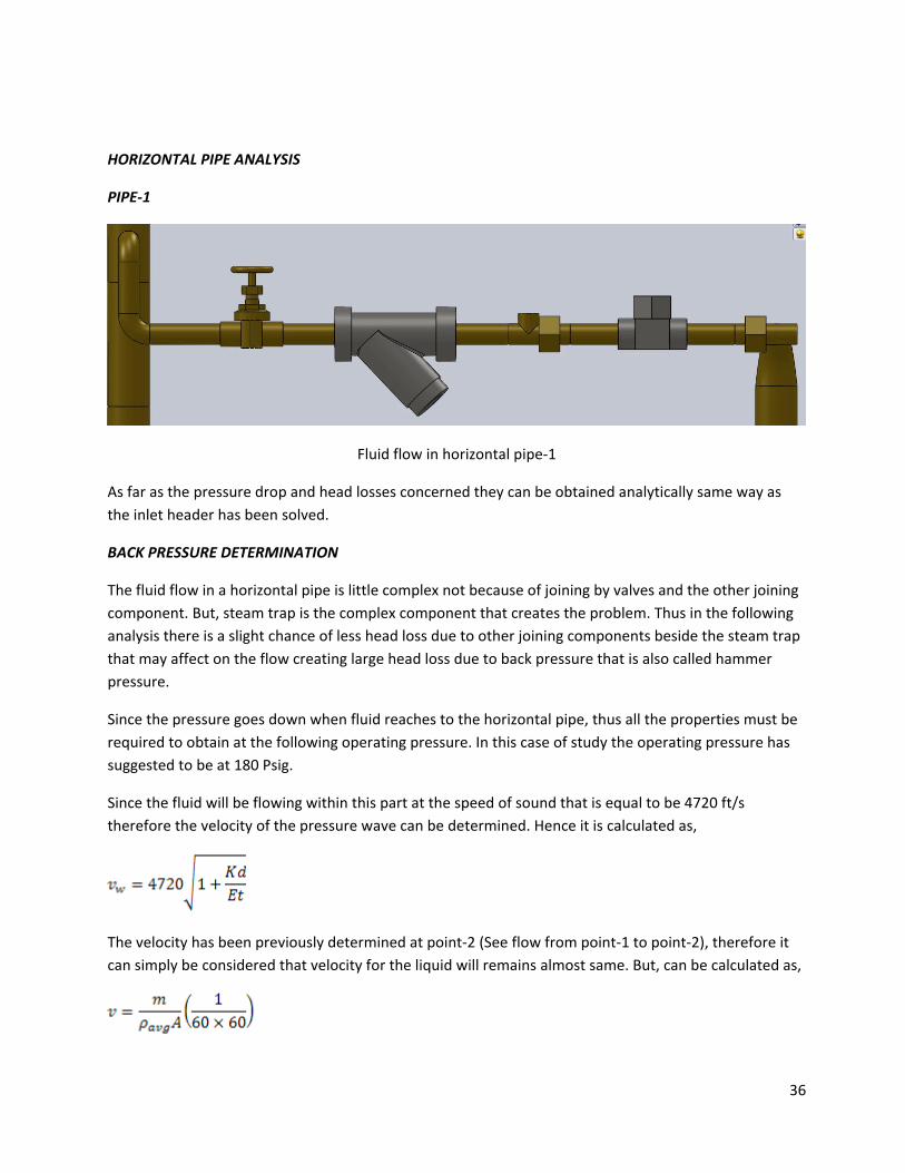
HORIZONTAL PIPE ANALYSIS
PIPE-1
Fluid flow in horizontal pipe-1
As far as the pressure drop and head losses concerned they can be obtained analytically same way as the inlet header has been solved.
BACK PRESSURE DETERMINATION
The fluid flow in a horizontal pipe is little complex not because of joining by valves and the other joining component. But, steam trap is the complex component that creates the problem. Thus in the following analysis there is a slight chance of less head loss due to other joining components beside the steam trap that may affect on the flow creating large head loss due to back pressure that is also called hammer pressure.
Since the pressure goes down when fluid reaches to the horizontal pipe, thus all the properties must be required to obtain at the following operating pressure. In this case of study the operating pressure has suggested to be at 180 Psig.
Since the fluid will be flowing within this part at the speed of sound that is equal to be 4720 ft/s therefore the velocity of the pressure wave can be determined. Hence it is calculated as,
The velocity has been previously determined at point-2 (See flow from point-1 to point-2), therefore it can simply be considered that velocity for the liquid will remains almost same. But, can be calculated as,
37
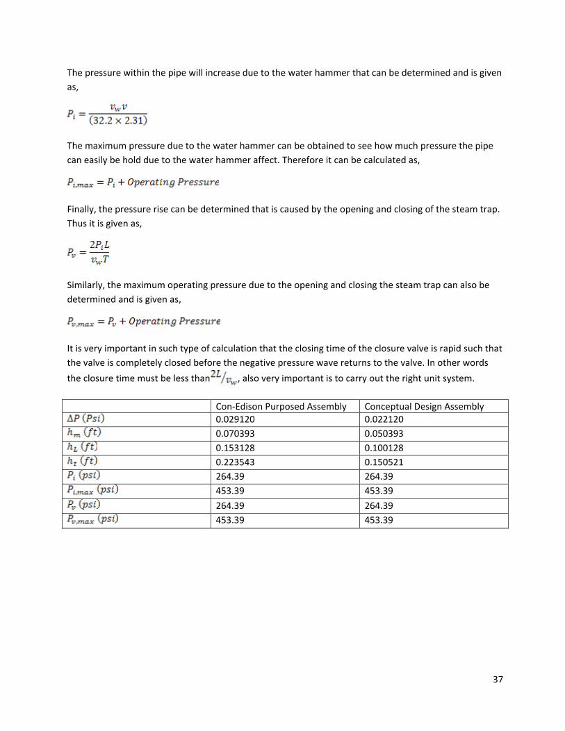
The pressure within the pipe will increase due to the water hammer that can be determined and is given as,
The maximum pressure due to the water hammer can be obtained to see how much pressure the pipe can easily be hold due to the water hammer affect. Therefore it can be calculated as,
Finally, the pressure rise can be determined that is caused by the opening and closing of the steam trap. Thus it is given as,
Similarly, the maximum operating pressure due to the opening and closing the steam trap can also be determined and is given as,
It is very important in such type of calculation that the closing time of the closure valve is rapid such that the valve is completely closed before the negative pressure wave returns to the valve. In other words
the closure time must be less than , also very important is to carry out the right unit system.
Con-Edison Purposed Assembly Conceptual Design Assembly
0.029120 0.022120
0.070393 0.050393
0.153128 0.100128
0.223543 0.150521
264.39 264.39
453.39 453.39
264.39 264.39
453.39 453.39
38
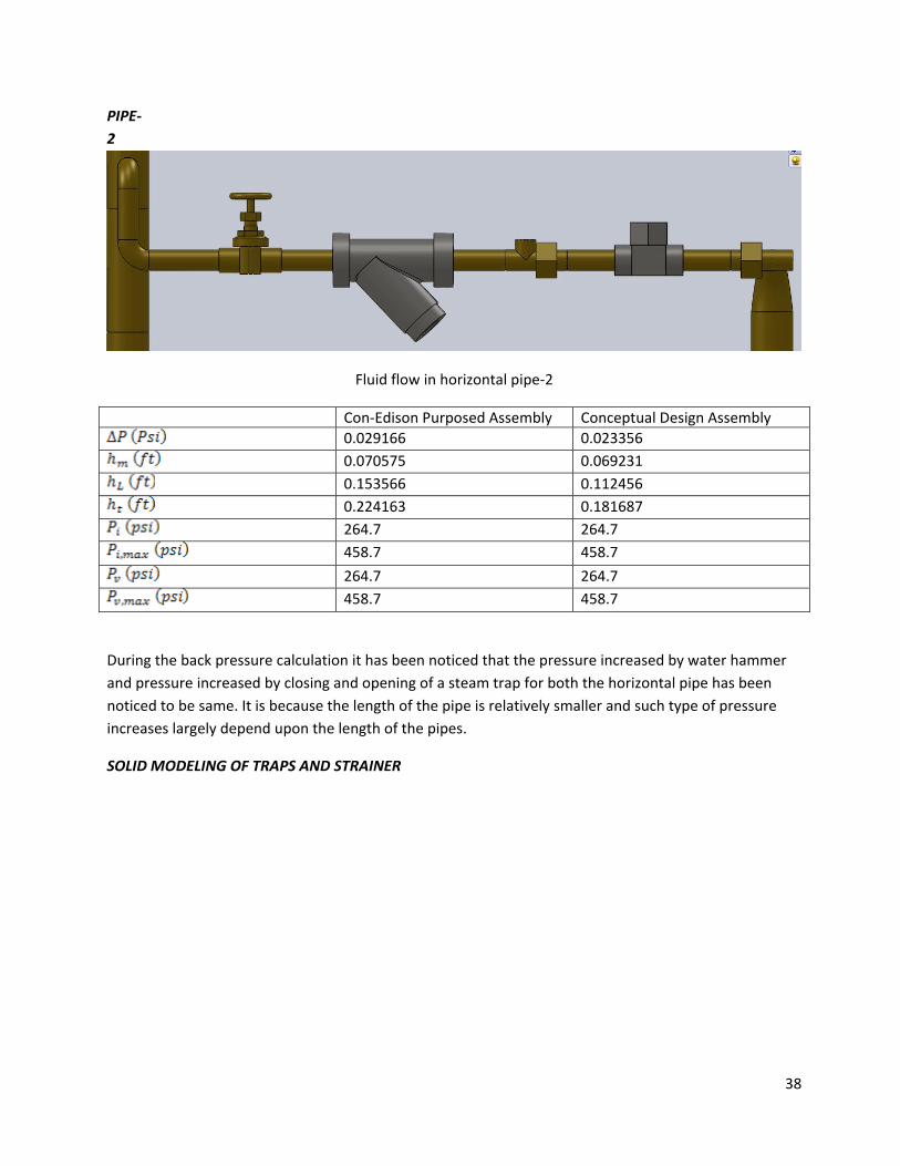
PIPE-2
Fluid flow in horizontal pipe-2
Con-Edison Purposed Assembly Conceptual Design Assembly
0.029166 0.023356
0.070575 0.069231
0.153566 0.112456
0.224163 0.181687
264.7 264.7
458.7 458.7
264.7 264.7
458.7 458.7
During the back pressure calculation it has been noticed that the pressure increased by water hammer and pressure increased by closing and opening of a steam trap for both the horizontal pipe has been noticed to be same. It is because the length of the pipe is relatively smaller and such type of pressure increases largely depend upon the length of the pipes.
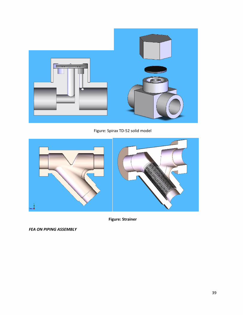
SOLID MODELING OF TRAPS AND STRAINER
39
Figure: Spirax TD-52 solid model
Figure: Strainer
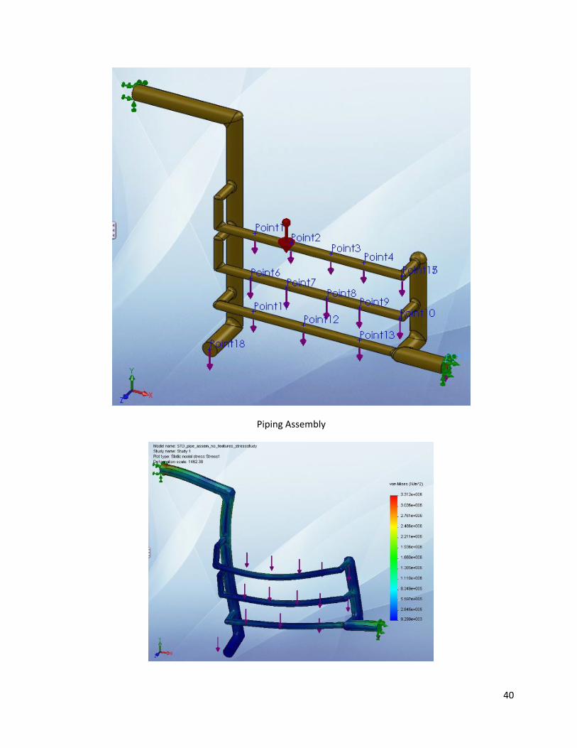
FEA ON PIPING ASSEMBLY
40
Piping Assembly
41
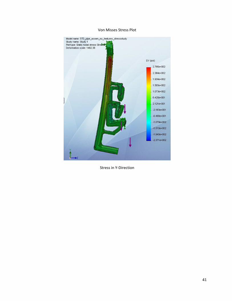
Von Misses Stress Plot
Stress in Y-Direction
42
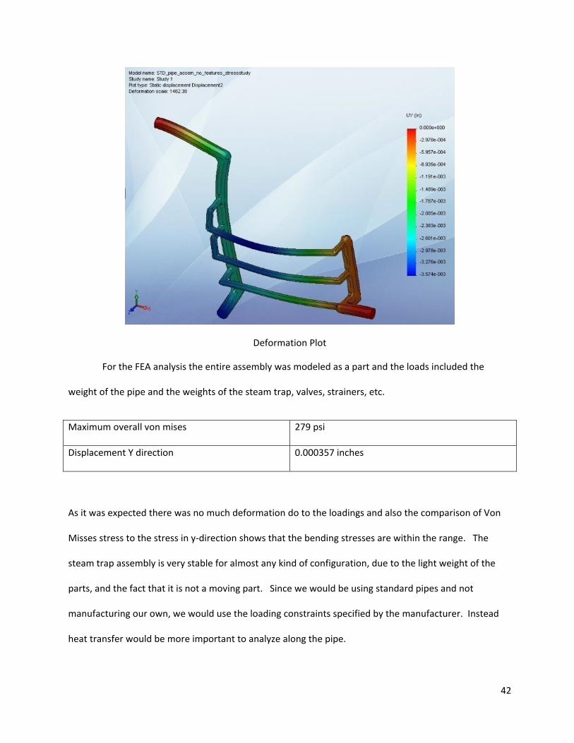
Deformation Plot
For the FEA analysis the entire assembly was modeled as a part and the loads included the
weight of the pipe and the weights of the steam trap, valves, strainers, etc.
Maximum overall von mises 279 psi
Displacement Y direction 0.000357 inches
As it was expected there was no much deformation do to the loadings and also the comparison of Von
Misses stress to the stress in y-direction shows that the bending stresses are within the range. The
steam trap assembly is very stable for almost any kind of configuration, due to the light weight of the
parts, and the fact that it is not a moving part. Since we would be using standard pipes and not
manufacturing our own, we would use the loading constraints specified by the manufacturer. Instead
heat transfer would be more important to analyze along the pipe.
43
Heat transfer
This report details the analysis and the result of the heat transfer analysis performed on the
steam trap. Heat losses due to friction and other factors such as convection and conduction through
valves, fittings and other piping elements are neglected here.
Before elaborating the formulas and the procedure used, we would like to specify the status of
our flow. Saturated Water, mainly condensate, flows through pipes until it reaches the steam trap
where most the steam is extracted from the mixture, condensed and drained along with the condensate
out to the pipe leading to the sewer.
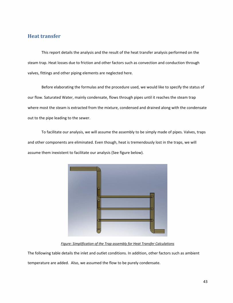
To facilitate our analysis, we will assume the assembly to be simply made of pipes. Valves, traps
and other components are eliminated. Even though, heat is tremendously lost in the traps, we will
assume them inexistent to facilitate our analysis (See figure below).
Figure: Simplification of the Trap assembly for Heat Transfer Calculations
The following table details the inlet and outlet conditions. In addition, other factors such as ambient
temperature are added. Also, we assumed the flow to be purely condensate.
44
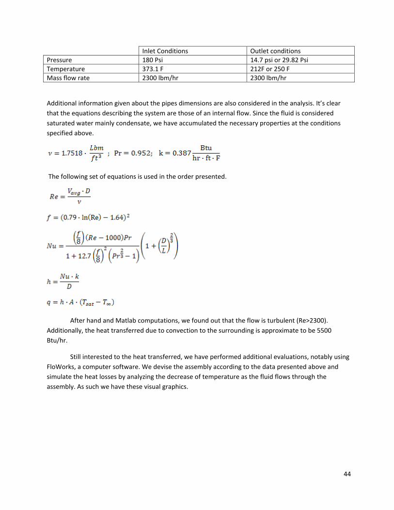
Inlet Conditions Outlet conditions Pressure 180 Psi 14.7 psi or 29.82 Psi Temperature 373.1 F 212F or 250 F Mass flow rate 2300 lbm/hr 2300 lbm/hr
Additional information given about the pipes dimensions are also considered in the analysis. It’s clear that the equations describing the system are those of an internal flow. Since the fluid is considered saturated water mainly condensate, we have accumulated the necessary properties at the conditions specified above.
The following set of equations is used in the order presented.
After hand and Matlab computations, we found out that the flow is turbulent (Re>2300). Additionally, the heat transferred due to convection to the surrounding is approximate to be 5500 Btu/hr.
Still interested to the heat transferred, we have performed additional evaluations, notably using FloWorks, a computer software. We devise the assembly according to the data presented above and simulate the heat losses by analyzing the decrease of temperature as the fluid flows through the assembly. As such we have these visual graphics.
45
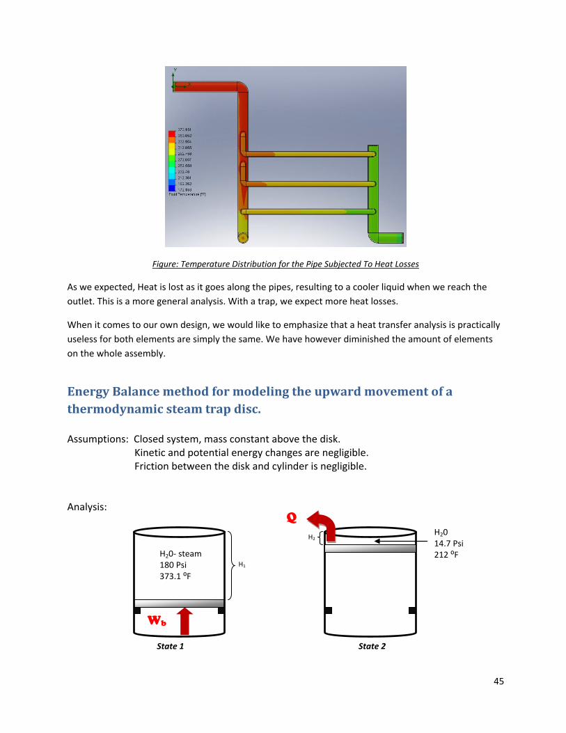
Figure: Temperature Distribution for the Pipe Subjected To Heat Losses
As we expected, Heat is lost as it goes along the pipes, resulting to a cooler liquid when we reach the outlet. This is a more general analysis. With a trap, we expect more heat losses.
When it comes to our own design, we would like to emphasize that a heat transfer analysis is practically useless for both elements are simply the same. We have however diminished the amount of elements on the whole assembly.
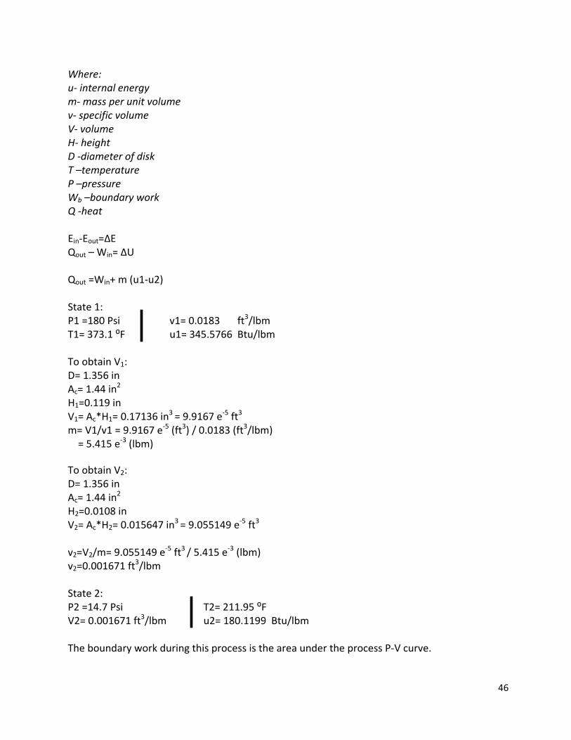
Energy Balance method for modeling the upward movement of a thermodynamic steam trap disc. Assumptions: Closed system, mass constant above the disk.
Kinetic and potential energy changes are negligible. Friction between the disk and cylinder is negligible.
Analysis:
H2
H20- steam 180 Psi 373.1 ⁰F
Q H20 14.7 Psi 212 ⁰F
State 1 State 2
Wb
H1
46
Where: u- internal energy m- mass per unit volume v- specific volume V- volume H- height D -diameter of disk T –temperature P –pressure Wb –boundary work Q -heat Ein-Eout=∆E Qout – Win= ∆U Qout =Win+ m (u1-u2) State 1: P1 =180 Psi v1= 0.0183 ft3/lbm T1= 373.1 ⁰F u1= 345.5766 Btu/lbm To obtain V1: D= 1.356 in Ac= 1.44 in2 H1=0.119 in V1= Ac*H1= 0.17136 in3 = 9.9167 e-5 ft3 m= V1/v1 = 9.9167 e-5 (ft3) / 0.0183 (ft3/lbm) = 5.415 e-3 (lbm) To obtain V2: D= 1.356 in Ac= 1.44 in2 H2=0.0108 in V2= Ac*H2= 0.015647 in3 = 9.055149 e-5 ft3 v2=V2/m= 9.055149 e-5 ft3 / 5.415 e-3 (lbm) v2=0.001671 ft3/lbm State 2: P2 =14.7 Psi T2= 211.95 ⁰F V2= 0.001671 ft3/lbm u2= 180.1199 Btu/lbm The boundary work during this process is the area under the process P-V curve.
47
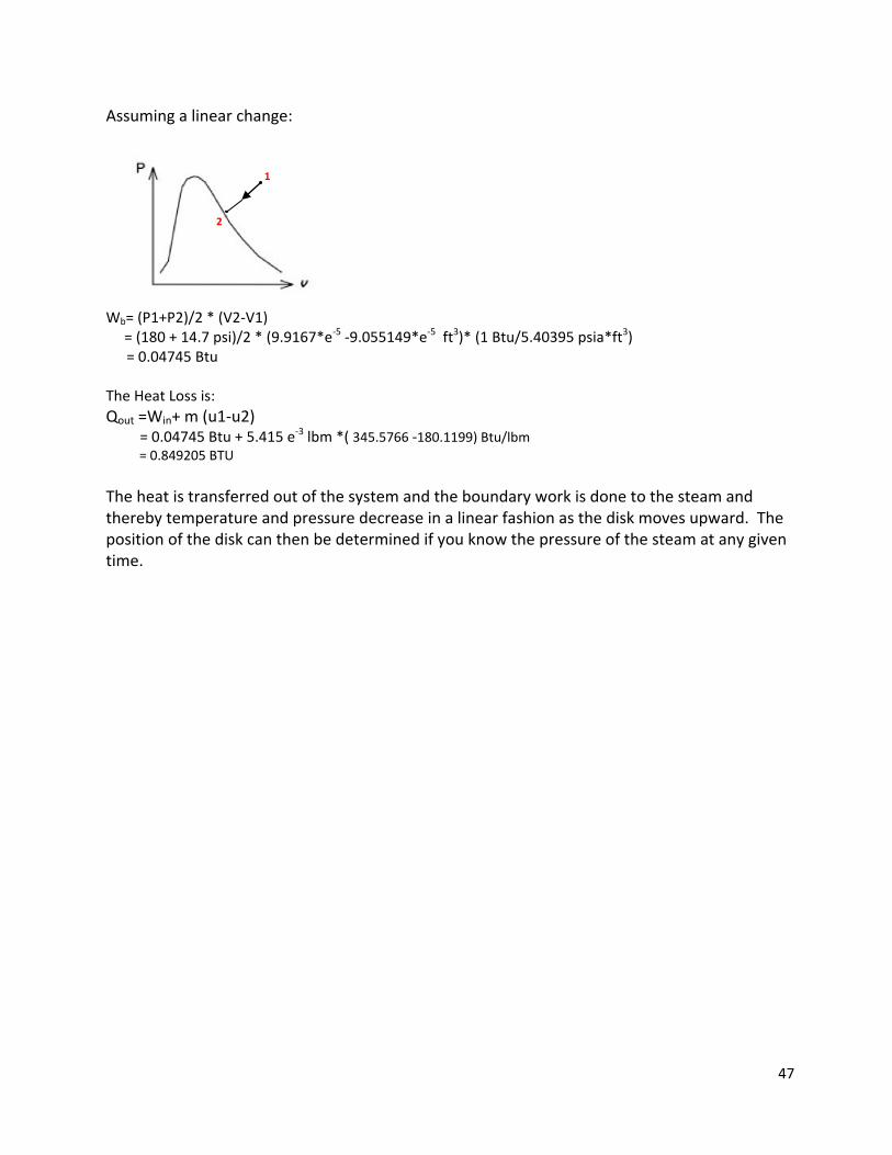
Assuming a linear change:
Wb= (P1+P2)/2 * (V2-V1) = (180 + 14.7 psi)/2 * (9.9167*e-5 -9.055149*e-5 ft3)* (1 Btu/5.40395 psia*ft3) = 0.04745 Btu The Heat Loss is: Qout =Win+ m (u1-u2) = 0.04745 Btu + 5.415 e-3 lbm *( 345.5766 -180.1199) Btu/lbm = 0.849205 BTU The heat is transferred out of the system and the boundary work is done to the steam and thereby temperature and pressure decrease in a linear fashion as the disk moves upward. The position of the disk can then be determined if you know the pressure of the steam at any given time.
1
2
48
NEW TECHNOLOGIES
Ultrasonic Flowmeters
An ultrasonic flow meter measures the velocity of a liquid or gas through a pipe using ultrasonic
transducers. The results are slightly affected by temperature, density or viscosity of the flowing medium.
Ultrasonic flowmeters operate on this principle, using sound waves in the ultrasonic range (typically at a
frequency of 1 MHz). Ultrasonic (or acoustic) flowmeters operate by generating sound waves with a
transducer and measuring the propagation of those waves through a flowing fluid. There are two basic
kinds of ultrasonic flowmeters: transit time and Doppler-effect (or frequency shift) flowmeters. The
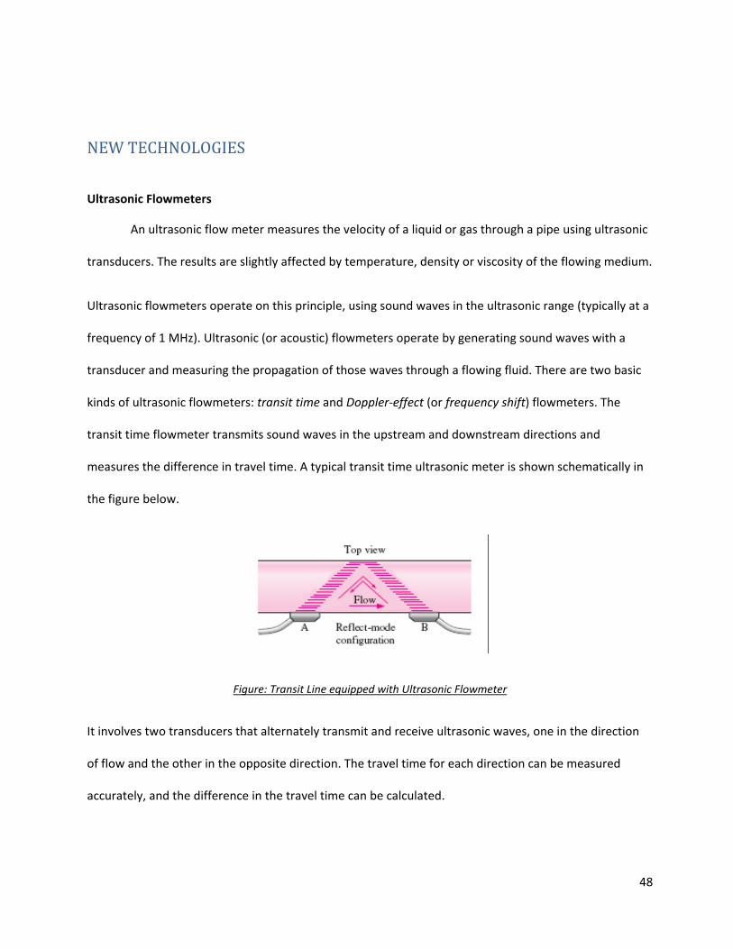
transit time flowmeter transmits sound waves in the upstream and downstream directions and
measures the difference in travel time. A typical transit time ultrasonic meter is shown schematically in
the figure below.
Figure: Transit Line equipped with Ultrasonic Flowmeter
It involves two transducers that alternately transmit and receive ultrasonic waves, one in the direction
of flow and the other in the opposite direction. The travel time for each direction can be measured
accurately, and the difference in the travel time can be calculated.
49
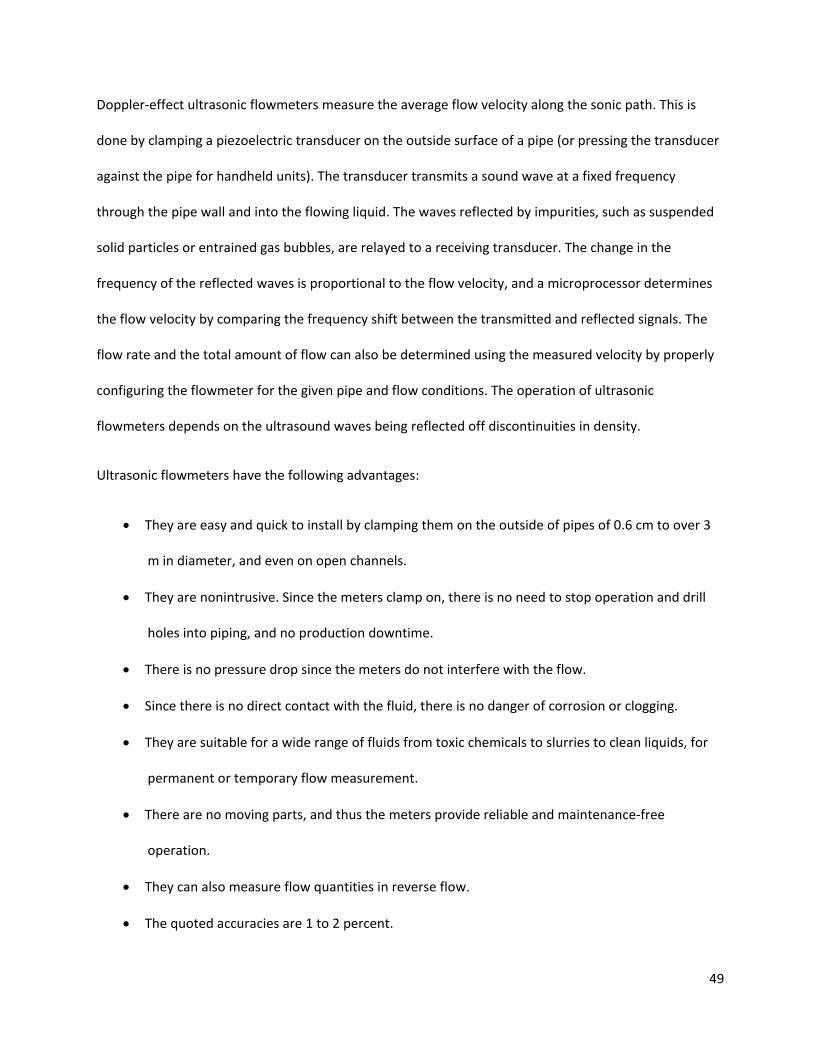
Doppler-effect ultrasonic flowmeters measure the average flow velocity along the sonic path. This is
done by clamping a piezoelectric transducer on the outside surface of a pipe (or pressing the transducer
against the pipe for handheld units). The transducer transmits a sound wave at a fixed frequency
through the pipe wall and into the flowing liquid. The waves reflected by impurities, such as suspended
solid particles or entrained gas bubbles, are relayed to a receiving transducer. The change in the
frequency of the reflected waves is proportional to the flow velocity, and a microprocessor determines
the flow velocity by comparing the frequency shift between the transmitted and reflected signals. The
flow rate and the total amount of flow can also be determined using the measured velocity by properly
configuring the flowmeter for the given pipe and flow conditions. The operation of ultrasonic
flowmeters depends on the ultrasound waves being reflected off discontinuities in density.
Ultrasonic flowmeters have the following advantages:
• They are easy and quick to install by clamping them on the outside of pipes of 0.6 cm to over 3
m in diameter, and even on open channels.
• They are nonintrusive. Since the meters clamp on, there is no need to stop operation and drill
holes into piping, and no production downtime.
• There is no pressure drop since the meters do not interfere with the flow.
• Since there is no direct contact with the fluid, there is no danger of corrosion or clogging.
• They are suitable for a wide range of fluids from toxic chemicals to slurries to clean liquids, for
permanent or temporary flow measurement.
• There are no moving parts, and thus the meters provide reliable and maintenance-free
operation.
• They can also measure flow quantities in reverse flow.
• The quoted accuracies are 1 to 2 percent.
50
Ultrasonic flowmeters are noninvasive devices, and the ultrasonic transducers can effectively transmit
signals through polyvinyl chloride (PVC), steel, iron, and brass walls. If added into our design, it will help
reduce the space used by the bushing adapter for the thermocouples. Plus, it will help prevent cloaking
and warn of air bubbles formations. Additional information as to pipe cloaking and sizes of debris
traveling in the flow can also be detected. This is can efficiently help prevent another explosion. Even
though being widespread on the market, we are still searching for a cheap ultrasonic flowmeters. They
tend to be very expenses.
A trap usually requires a valve (maybe two, one upstream and one downstream), a strainer or a filtering
system, a most importantly a by-pass system, in case of cloaking. These elements along with piping
connections in between following different arrangements produce a steam trap assembly. Our design
simply combines a steam trap with a strainer with by-pass system associated with each line, parallel to
the main-line.
While researching new and yet efficient technologies, we encountered different types of elements. One
that certainly caught our attention, for its simplicity, is the Velan Forged Piping King Automatic
Condensate Drain Units ®.The Piping King Package unit fitted with a bypass, enables the steam trap to
be isolated from the system allowing routine maintenance to be carried out.
The unit consists of a steam trap with integral strainer and check valve and of two high-quality forged
steel special stop check globe valves mounted on either side of the trap. The valves are connected by
the bypass pipe, enabling the steam trap to be isolated while the steam flow is maintained. The
manufacturers are proud to specify that it reduces spaces in assembly and easy to mount, as it is shown
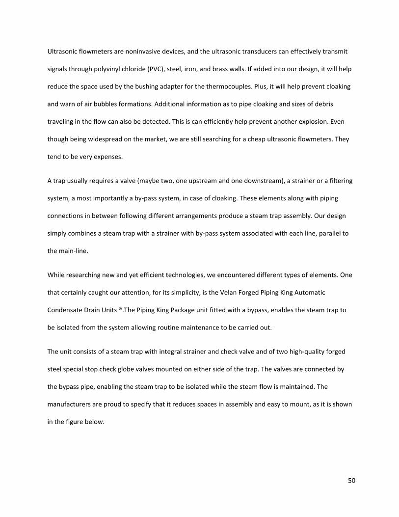
in the figure below.
51
Figure: Graphics Depicting the Utility and the Space-Saving of the Piping King Units
The working principal of the Piping King Units is simple. We will break it up in 4 steps:
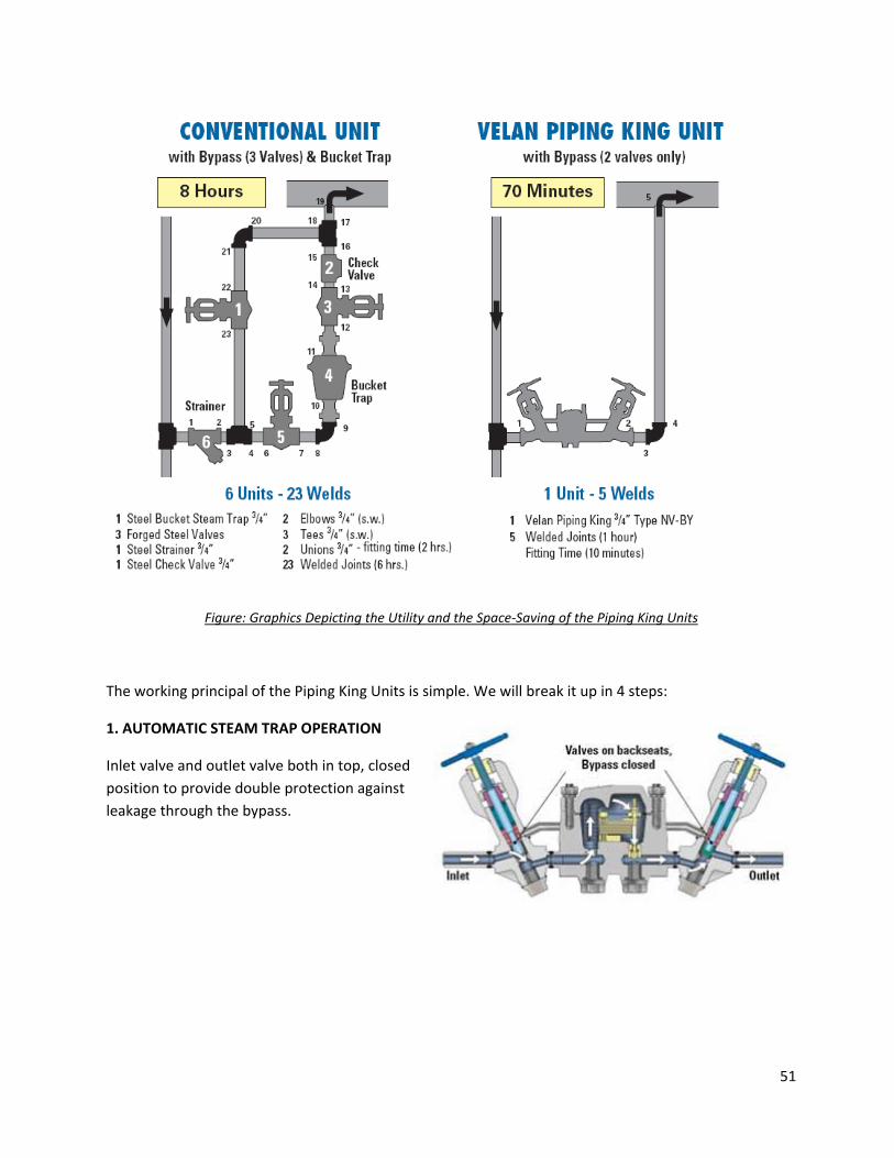
1. AUTOMATIC STEAM TRAP OPERATION
Inlet valve and outlet valve both in top, closed position to provide double protection against leakage through the bypass.
52
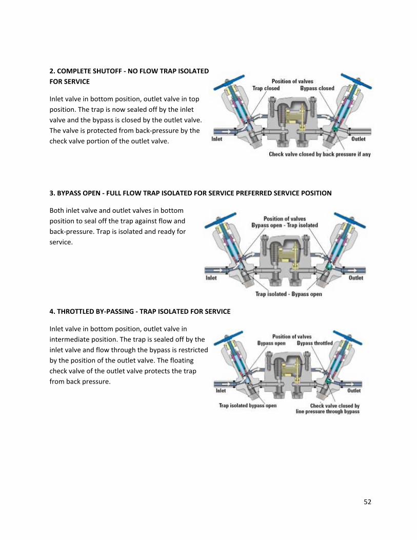
2. COMPLETE SHUTOFF - NO FLOW TRAP ISOLATED FOR SERVICE
Inlet valve in bottom position, outlet valve in top position. The trap is now sealed off by the inlet valve and the bypass is closed by the outlet valve. The valve is protected from back-pressure by the check valve portion of the outlet valve.
3. BYPASS OPEN - FULL FLOW TRAP ISOLATED FOR SERVICE PREFERRED SERVICE POSITION
Both inlet valve and outlet valves in bottom position to seal off the trap against flow and back-pressure. Trap is isolated and ready for service.
4. THROTTLED BY-PASSING - TRAP ISOLATED FOR SERVICE
Inlet valve in bottom position, outlet valve in intermediate position. The trap is sealed off by the inlet valve and flow through the bypass is restricted by the position of the outlet valve. The floating check valve of the outlet valve protects the trap from back pressure.
53
Velan Piping Kings can be installed in any position, and require only a minimal amount of space.
This can be a great element in our assembly. It will reduce down our trap assembly to a few elements.
Costs of the system are unknown of us as of now. However, we have noticed that it can be simply to
manufacture such a steam trap if we are given the chances and the necessary tools to do so.
Even though untested, we are sure that these technologies specified above can easily be
adjusted t our design. However, the main key is to determine whether they will be not only efficient and
useful to our conditions but also cost efficient. We will still look for better and yet simpler designs for
our assembly, and continue to improve its capacity.
54
CONCLUSION
This semester, we have taken upon the task of designing a new steam trap assembly for our
senior design project. We have analyzed the design proposed by Con Edison, as a pedestal on which we
raise our design. For that, we have focused our analysis on the heat transfer, the stress analysis and the
fluid dynamics. This has allowed us to situate and improve our objective.
We have decided to choose this design for we have a common interest in steam production and
distribution. We also noted that it looked challenging. We expected a challenging problem to work on
because that will give us enough experience when it comes to engineering. At the same time, this
project does not only deal with High temperature and pressure but it also analyzes complex piping
structures. This is a good project in the sense it has allowed us to apply all the engineering knowledge
we have accumulated during our education.
As challenging it was, we had to face many frustrations in the sense where not a lot of literature
was available, literature that dealt with the mathematical analysis of steam trap assemblies. We have
gone through a lot of research and tutorials. We are glad that we have finally come to satisfying results.
We had hard time learning new software to realize a FEM analysis on the model. Plus, designing a new
model revealed to be harder than expected. We were restrained by the constraints specified earlier.
However, we have come to develop a more efficient design.
We are hoping to be able to develop an actual model of our assembly next semester and we are
expecting to be able to run it under normal conditions. Also, we will continue analyzing our design for
better performance. Analytical solutions will be implemented and we will continue searching for better,
cheaper and efficient technologies and ideas to implement in our design.
55
REFERENCES
1. 2007 New York City steam explosion
http://en.wikipedia.org/wiki/2007_New_York_City_steam_explosion
2. Bill Harms, Water hammer in steam systems: cause and effect, “Mechanical Engineering”
3. Lucius Pitkin, Inc, Consulting Engineers, “July 18 2007 Steam Incident 41st Street and Lexington
Ave, New York, NY, Volume 1.
4. ABS Consulting, Risk Consulting Division, “July 18 2007 Steam Incident 41st Street and Lexington
Ave, New York, NY”
5. Con Edison Steam Operations, “Steam Operations: An overview”, Powerpoint presentation
6. Bevelhymer, Carl, “Steam”,
http://www.gothamgazette.com/article/issueoftheweek/20031110/200/674
7. Hicks Tyler G, Standard Handbook of Engineering Calculations, “Water Hammer Effects in Liquid
Pipelines”, page#3-282-383, McGraw Hill, Inc. 0-07028734-1 (ISBN), TA151H52 (CCNY Catalog).
8. Eshbach, Handbook of Engineering Fundamentals, Mechanics of Incompressible Fluid, “Water
Hammer”, page#627-628, Wiley Handbook Series, 0-47124553-4 (ISBN), TA151E8, 3rd edition.
9. Cengel Yunus A & Cimbala John A, Fluid Mechanics Fundamentals And Applications, 0-07-
247236-7 (ISBN)
10. Liu Cheng & Evett Jack B, Fundamentals of Fluid Mechanics, McGraw-Hills, Inc. 0-07-0197792
(ISBN).
11. Nayyar Mohinder L, Piping Handbook, “Stress Analysis of Piping System”, McGraw-Hill Inc. 0-07-
047106-1 (ISBN), 7th edition.
12. Avallone Eugene A, Sadegh Ali & Baumeister III Theodore, Mark’s Standard Handbook for
Mechanical Engineers, McGraw-Hill Inc. 0-07-004997-1 (ISBN), 11th edition.
13. "Selecting the right steam trap" by S.P. Frank, Richard Industries Inc.
56
14. "User's view of steam traps" by Michael Lauber, PE/CEM Continental Tire North America
15. "Steam Traps Engineering Data Manual" Hoffman Specialty
16. Heat Transfer Essentials, Latif Jiji, 2nd Edition, 2002.
17. Acoustic sensors, www.netl.doe.gov. December 2008
18. Sensors technology, www.thomasnet.com.December 2008
19. Velan Valves, www.velansteamtraps.com. 2006.


![steam trap performance[1]](https://img.pdfslide.net/doc/110x75/551b18ab4a795911748b45cc/steam-trap-performance1.jpg)