Embed Size (px)
DESCRIPTION
STEM Construccion de Un Dron
Citation preview
http://www.teachstemnow.com/ Students Fly High With CNC Machined Quadcopters M A Y 3 R D , 2 0 1 4 B Y A L C H I R I N I A N
The study of robotics has proven over the years to be the perfect storm for STEM
education. Robots are highly visible in the media and recognized as complex,
captivating machines that represent the future of innovators in today’s
classroom. Students who build robots are provided with a unique opportunity to think
for themselves as they troubleshoot problems and stay engaged with high level science
and engineering practices. Skills in programming, advanced manufacturing and design
become second nature to students who have been through a comprehensive robotics-
based STEM program.
Aerial robots can fill a similar role in your STEM program, with the added dimension
of flight control. Often referred to as multi-rotor copters or just multicopters, these
devices are fascinating to watch, fun to fly, and are in the media spotlight enough to
make even the layperson aware that students working on them must be doing something
important. Multicopters in the field are used for surveillance, photography, mapping
farmland, scientific research, and search and rescue. For educators who use robotics to
engage students in genuine science and engineering practices, multicopters provide
another way to develop and refine news layers of technical and problem solving skills
that make sense for the demands of today’s workplace.
While there are many parallel skills developed with terrestrial robotics, multicopters
require specialized skill to operate and are a bit more demanding in terms of
manufacturing tolerances, programming and balance than most classroom project
robots. Teachers who are accustomed to seeing junkbots (robots made from recycled
materials) wobbling around the room will need to help hone students abilities to make
accurate and repeatable parts. CNC machines are made specifically for accuracy and
repeatability, so taking advantage of this capability is a key focus of this series.
Building multicopters from scratch is not a simple undertaking. The machines and their
operation is complicated, and they can be dangerous if proper precautions are not taken.
The cost of components is far lower than at any time in the past, but they are not an
inexpensive item. However, the immense payoff for students is worth the initial
trepidation and time required to make multicopters work for you and your class room.
TeachSTEMNow has dedicated this series to removing obstacles by providing specific,
classroom-proven instructions, low cost component and supplier recommendations,
addressing safety issues, and project management guidelines that will make
multicopters a new step in your STEM revolution.
Multicopters are named based on the number of rotors present. Octocopters have eight
rotors, hexacopters have six, and so on. A four-rotor quadcopter is a good compromise
between cost and functionality, making it the most popular choice for general use. In
this STEM tutorial series teachers lead students to manufacture, test and tune their own
quadcopter made using CNC.
Key Concepts and Take Home Skills: Aeronautics/Physics of Flight
CAD/CAM/Advanced Manufacturing
Energy/Sustainability
Electronics/Soldering/Wiring
Critical Thinking and Problem Solving
What You Need To Get Started: As teachers, research is something we are accustomed to doing when learning how to
improve our content knowledge, instructional strategies, and classroom management
skills. If you are reading this article, you are doing research now. The recommendations
we provide here for components are for just one variation of the many choices
available. If you purchase these components, they are known to work in the
configuration shown. However, you are just as likely on your own to find performance
and value equal to or better than these with some additional research. But for those who
just want a list of what to buy and get their students flying, these bits are proven.
One of the most interesting parts of building a quadcopter from scratch is the process of
choosing component parts. We will discuss in detail the functions of these quadcopter
parts and components later in the tutorials. It is essential to know how these parts
interact in addition to their functions, because there is a domino effect in place. When
you choose one component, it affects the other parts in terms of compatibility and
capability. Again, this process will be clarified later for your students to be able to do
original designs. For now, this list is a proven set of parts that will work well with the
designs here for download.
Electronic Components
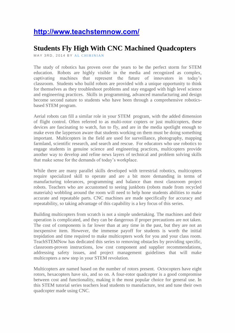
1. Transmitter and Receiver These components allow wireless control of the quadcopter. The transmitter is held in
the hands and sends signals to the receiver on the aircraft. You will want a 2.4 ghz
receiver/transmitter combination designed for simplicity and at least five channels. You
will use four of the channels for each of the motors, and one for activating the self
leveling function of the flight controller. If you don’t know what that means, don’t
worry about it. Just get five channels. A good buy at ServoCity is the HiTec Optic
5 transmitter and minima 6e receiver available for under $90.00. Another option is
the FlySky FS-T6 at HobbyPartz. This combination is an exceptional buy at the moment
with a price as of this writing of under $55.00.
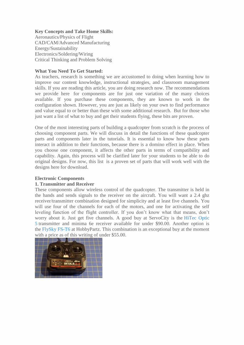
2. Flight Controller Multicopters rely on sophisticated electronic sensors such as gyroscopes and
accelerometers to achieve balance during flight. The job of the flight controller is to
coordinate the desires of the pilot with the data from the sensors while properly
regulating the speeds of each motor/propeller. The simplest flight controller to use is
the Hobbyking KK2.1. Unlike other flight controllers, this board does not need to be
interfaced with a computer for programming. It has the convenience of an on board
LCD panel and easy to use menu which allows the user to configure the ‘copter in the
field. As with all HobbyKing products mentioned in this article, try to find the item
from the US warehouse if possible. If it is out of stock there, then you will need to get it
from the international warehouse which usually means a delivery time of 3 weeks or so.
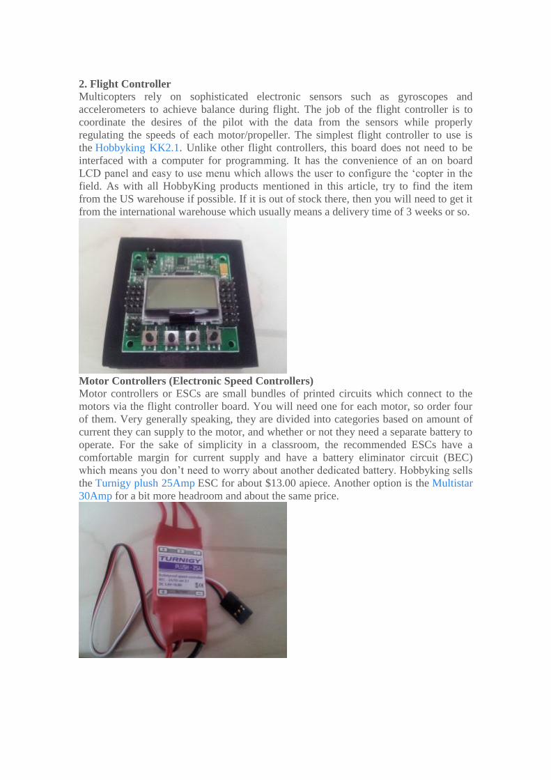
Motor Controllers (Electronic Speed Controllers) Motor controllers or ESCs are small bundles of printed circuits which connect to the
motors via the flight controller board. You will need one for each motor, so order four
of them. Very generally speaking, they are divided into categories based on amount of
current they can supply to the motor, and whether or not they need a separate battery to
operate. For the sake of simplicity in a classroom, the recommended ESCs have a
comfortable margin for current supply and have a battery eliminator circuit (BEC)
which means you don’t need to worry about another dedicated battery. Hobbyking sells
the Turnigy plush 25Amp ESC for about $13.00 apiece. Another option is the Multistar
30Amp for a bit more headroom and about the same price.
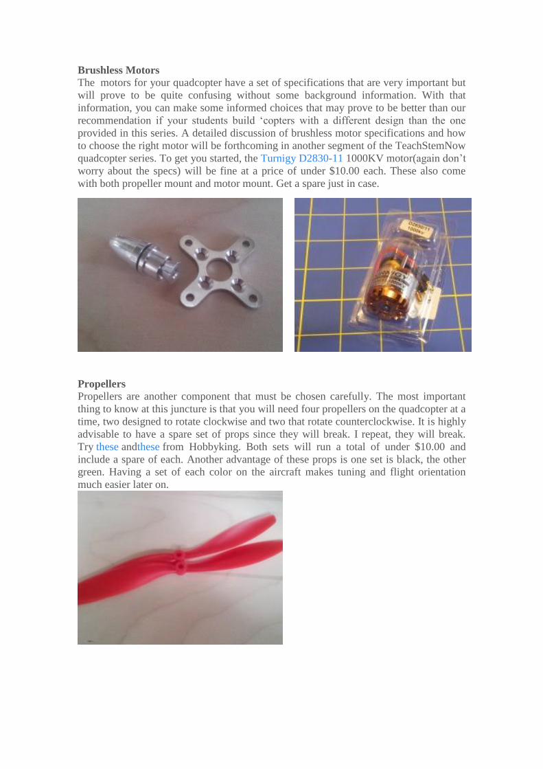
Brushless Motors The motors for your quadcopter have a set of specifications that are very important but
will prove to be quite confusing without some background information. With that
information, you can make some informed choices that may prove to be better than our
recommendation if your students build ‘copters with a different design than the one
provided in this series. A detailed discussion of brushless motor specifications and how
to choose the right motor will be forthcoming in another segment of the TeachStemNow
quadcopter series. To get you started, the Turnigy D2830-11 1000KV motor(again don’t
worry about the specs) will be fine at a price of under $10.00 each. These also come
with both propeller mount and motor mount. Get a spare just in case.
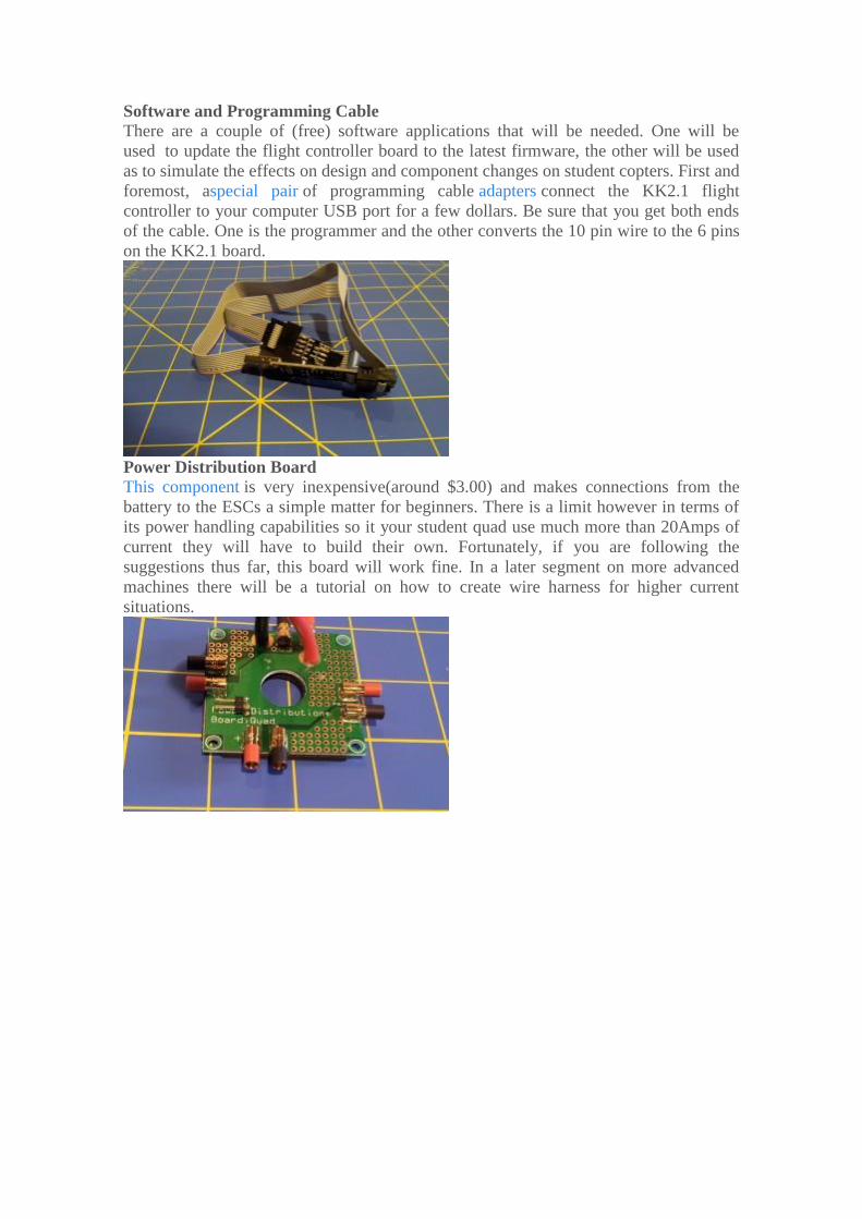
Propellers Propellers are another component that must be chosen carefully. The most important
thing to know at this juncture is that you will need four propellers on the quadcopter at a
time, two designed to rotate clockwise and two that rotate counterclockwise. It is highly
advisable to have a spare set of props since they will break. I repeat, they will break.
Try these andthese from Hobbyking. Both sets will run a total of under $10.00 and
include a spare of each. Another advantage of these props is one set is black, the other
green. Having a set of each color on the aircraft makes tuning and flight orientation
much easier later on.
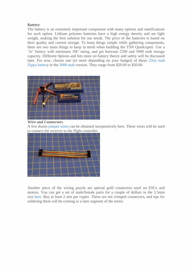
Software and Programming Cable There are a couple of (free) software applications that will be needed. One will be
used to update the flight controller board to the latest firmware, the other will be used
as to simulate the effects on design and component changes on student copters. First and
foremost, aspecial pair of programming cable adapters connect the KK2.1 flight
controller to your computer USB port for a few dollars. Be sure that you get both ends
of the cable. One is the programmer and the other converts the 10 pin wire to the 6 pins
on the KK2.1 board.
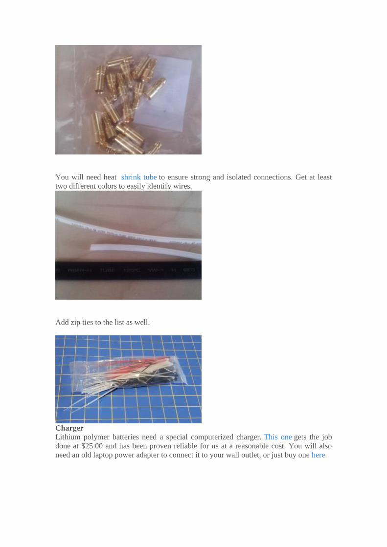
Power Distribution Board This component is very inexpensive(around $3.00) and makes connections from the
battery to the ESCs a simple matter for beginners. There is a limit however in terms of
its power handling capabilities so it your student quad use much more than 20Amps of
current they will have to build their own. Fortunately, if you are following the
suggestions thus far, this board will work fine. In a later segment on more advanced
machines there will be a tutorial on how to create wire harness for higher current
situations.
Battery The battery is an extremely important component with many options and ramifications
for each option. Lithium polymer batteries have a high energy density and are light
weight, making the best solution for our needs. The price of the batteries is based on
their quality and current storage. To keep things simple while gathering components,
there are two main things to keep in mind when building the TSN Quadcopter. Use a
‘3s’ battery with minimum 30C rating, and get between 2200 and 5000 mah storage
capacity. Different 0ptions and lots more on battery theory and safety will be discussed
later. For now, choose one (or more depending on your budget) of these: 22oo mah
Zippy battery or the 5000 mah version. They range from $20.00 to $50.00.
Wire and Connectors A few dozen jumper wires can be obtained inexpensively here. These wires will be used
to connect the receiver to the flight controller.
Another piece of the wiring puzzle are special gold connectors used on ESCs and
motors. You can get a set of male/female pairs for a couple of dollars in the 3.5mm
size here. Buy at least 2 sets per copter. These are not crimped connectors, and tips for
soldering them will be coming in a later segment of the series.
You will need heat shrink tube to ensure strong and isolated connections. Get at least
two different colors to easily identify wires.
Add zip ties to the list as well.
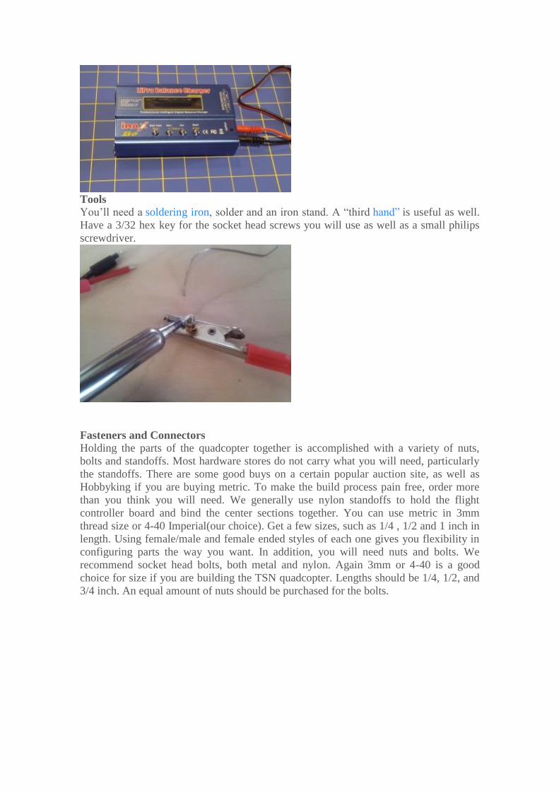
Charger Lithium polymer batteries need a special computerized charger. This one gets the job
done at $25.00 and has been proven reliable for us at a reasonable cost. You will also
need an old laptop power adapter to connect it to your wall outlet, or just buy one here.
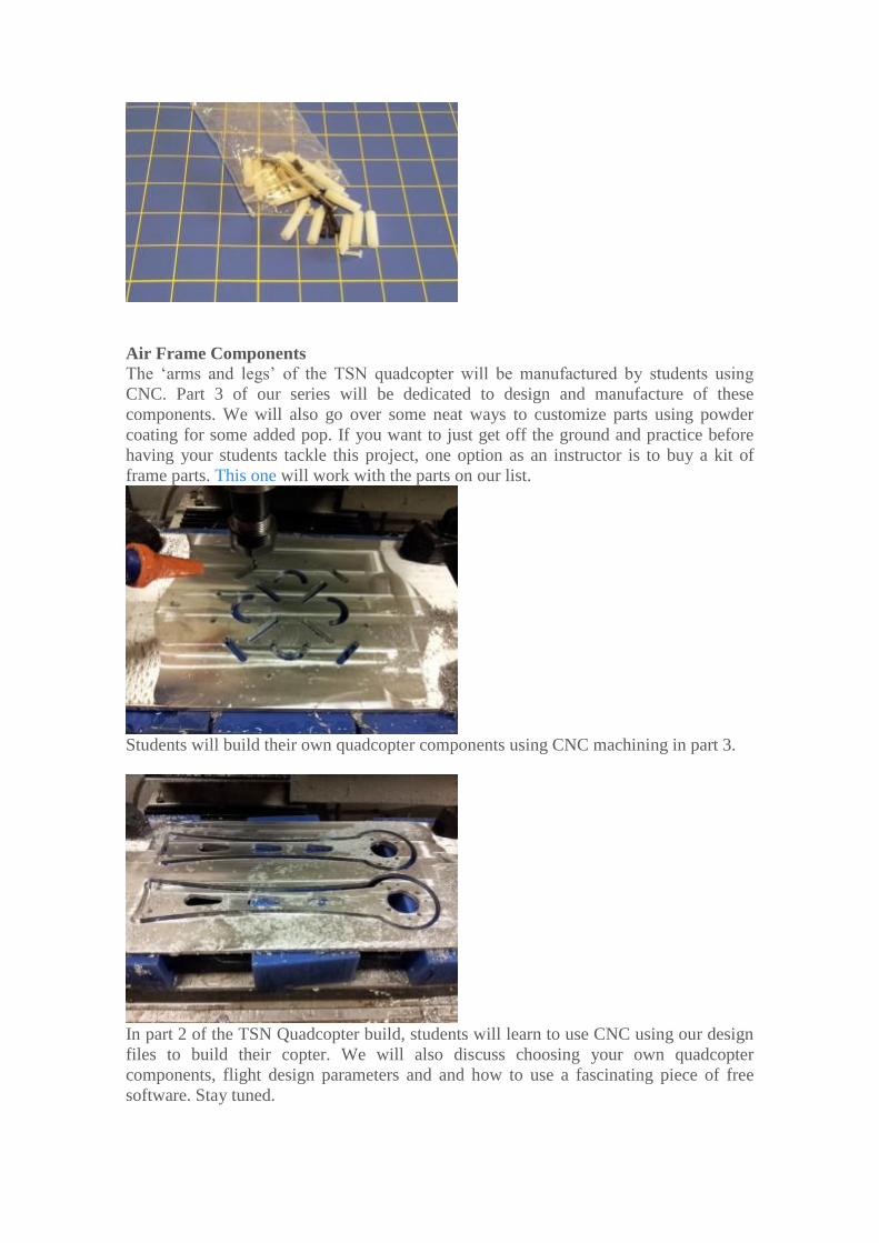
Tools You’ll need a soldering iron, solder and an iron stand. A “third hand” is useful as well.
Have a 3/32 hex key for the socket head screws you will use as well as a small philips
screwdriver.
Fasteners and Connectors Holding the parts of the quadcopter together is accomplished with a variety of nuts,
bolts and standoffs. Most hardware stores do not carry what you will need, particularly
the standoffs. There are some good buys on a certain popular auction site, as well as
Hobbyking if you are buying metric. To make the build process pain free, order more
than you think you will need. We generally use nylon standoffs to hold the flight
controller board and bind the center sections together. You can use metric in 3mm
thread size or 4-40 Imperial(our choice). Get a few sizes, such as 1/4 , 1/2 and 1 inch in
length. Using female/male and female ended styles of each one gives you flexibility in
configuring parts the way you want. In addition, you will need nuts and bolts. We
recommend socket head bolts, both metal and nylon. Again 3mm or 4-40 is a good
choice for size if you are building the TSN quadcopter. Lengths should be 1/4, 1/2, and
3/4 inch. An equal amount of nuts should be purchased for the bolts.
Air Frame Components The ‘arms and legs’ of the TSN quadcopter will be manufactured by students using
CNC. Part 3 of our series will be dedicated to design and manufacture of these
components. We will also go over some neat ways to customize parts using powder
coating for some added pop. If you want to just get off the ground and practice before
having your students tackle this project, one option as an instructor is to buy a kit of
frame parts. This one will work with the parts on our list.
Students will build their own quadcopter components using CNC machining in part 3.
In part 2 of the TSN Quadcopter build, students will learn to use CNC using our design
files to build their copter. We will also discuss choosing your own quadcopter
components, flight design parameters and and how to use a fascinating piece of free
software. Stay tuned.
Flying High With Aerial Robots part 2: Design
and Compromise J U L Y 7 T H , 2 0 1 4 B Y A L C H I R I N I A N
Competing for Compromise:Air Frame Design Considerations In this lesson students will learn about the different parts of the quadcopter air frame:
their functions, and things to consider when designing these parts to achieve sufficient
lift to get airborne. Students will make use of an online calculation tool that helps guide
their choices based on parameters selected by the instructor. Here they learn first hand
the art and science of compromise based on the goals of an engineering project. First, an
introduction to the air frame components.
Most multirotor airframes have several common components, some of which may be
separate or combined as modules. They include:
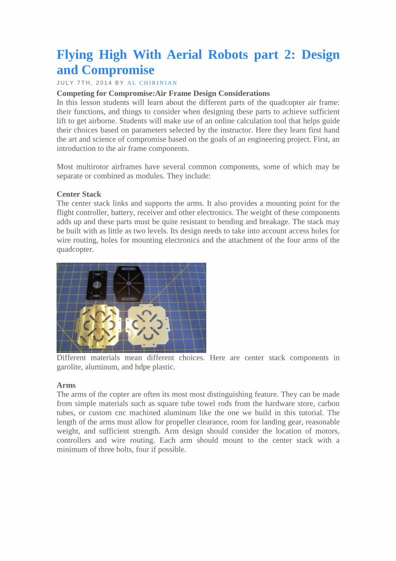
Center Stack The center stack links and supports the arms. It also provides a mounting point for the
flight controller, battery, receiver and other electronics. The weight of these components
adds up and these parts must be quite resistant to bending and breakage. The stack may
be built with as little as two levels. Its design needs to take into account access holes for
wire routing, holes for mounting electronics and the attachment of the four arms of the
quadcopter.
Different materials mean different choices. Here are center stack components in
garolite, aluminum, and hdpe plastic.
Arms The arms of the copter are often its most most distinguishing feature. They can be made
from simple materials such as square tube towel rods from the hardware store, carbon
tubes, or custom cnc machined aluminum like the one we build in this tutorial. The
length of the arms must allow for propeller clearance, room for landing gear, reasonable
weight, and sufficient strength. Arm design should consider the location of motors,
controllers and wire routing. Each arm should mount to the center stack with a
minimum of three bolts, four if possible.
Students may be tempted with ultralight materials, but some such as acrylic on the right
are not appropriate for an arm in this configuration. Aluminum is a good compromise.
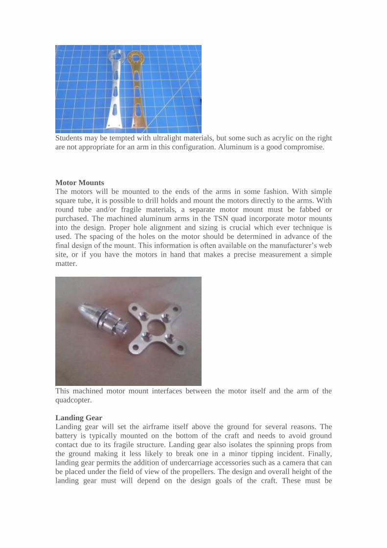
Motor Mounts The motors will be mounted to the ends of the arms in some fashion. With simple
square tube, it is possible to drill holds and mount the motors directly to the arms. With
round tube and/or fragile materials, a separate motor mount must be fabbed or
purchased. The machined aluminum arms in the TSN quad incorporate motor mounts
into the design. Proper hole alignment and sizing is crucial which ever technique is
used. The spacing of the holes on the motor should be determined in advance of the
final design of the mount. This information is often available on the manufacturer’s web
site, or if you have the motors in hand that makes a precise measurement a simple
matter.
This machined motor mount interfaces between the motor itself and the arm of the
quadcopter.
Landing Gear Landing gear will set the airframe itself above the ground for several reasons. The
battery is typically mounted on the bottom of the craft and needs to avoid ground
contact due to its fragile structure. Landing gear also isolates the spinning props from
the ground making it less likely to break one in a minor tipping incident. Finally,
landing gear permits the addition of undercarriage accessories such as a camera that can
be placed under the field of view of the propellers. The design and overall height of the
landing gear must will depend on the design goals of the craft. These must be
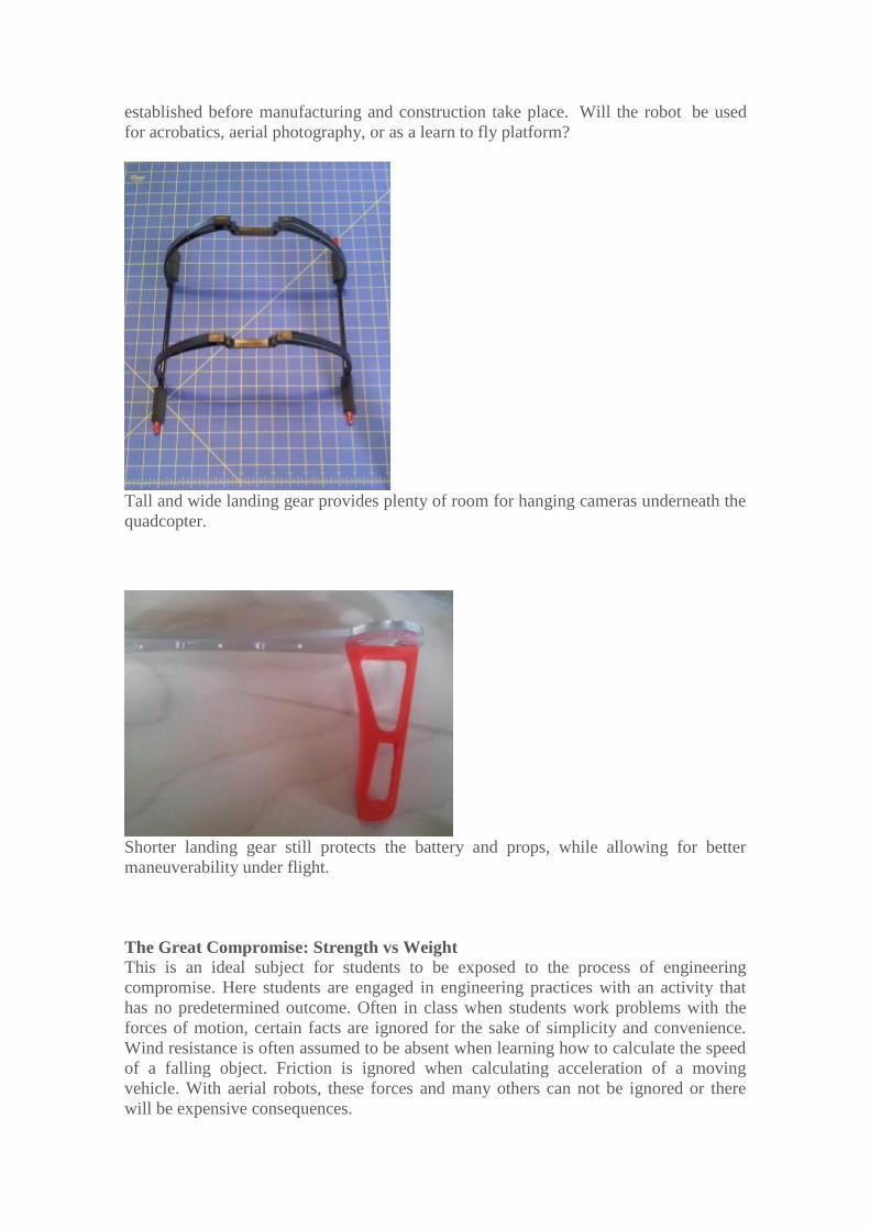
established before manufacturing and construction take place. Will the robot be used
for acrobatics, aerial photography, or as a learn to fly platform?
Tall and wide landing gear provides plenty of room for hanging cameras underneath the
quadcopter.
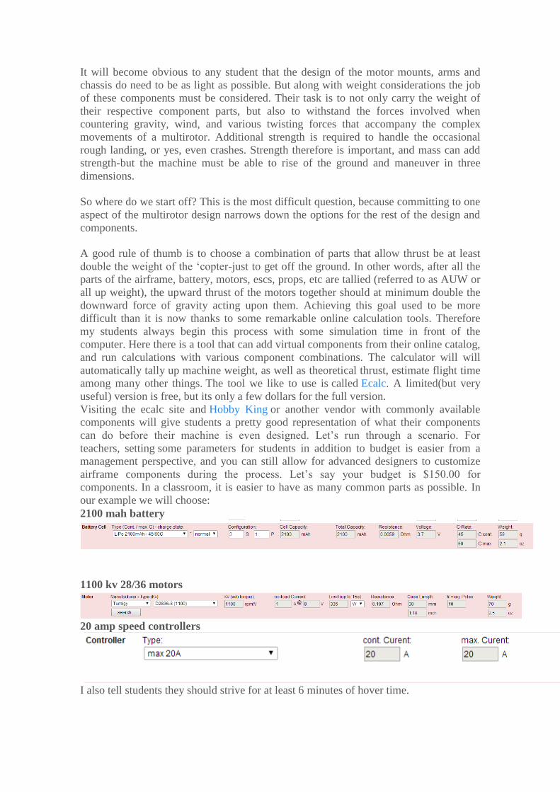
Shorter landing gear still protects the battery and props, while allowing for better
maneuverability under flight.
The Great Compromise: Strength vs Weight This is an ideal subject for students to be exposed to the process of engineering
compromise. Here students are engaged in engineering practices with an activity that
has no predetermined outcome. Often in class when students work problems with the
forces of motion, certain facts are ignored for the sake of simplicity and convenience.
Wind resistance is often assumed to be absent when learning how to calculate the speed
of a falling object. Friction is ignored when calculating acceleration of a moving
vehicle. With aerial robots, these forces and many others can not be ignored or there
will be expensive consequences.
It will become obvious to any student that the design of the motor mounts, arms and
chassis do need to be as light as possible. But along with weight considerations the job
of these components must be considered. Their task is to not only carry the weight of
their respective component parts, but also to withstand the forces involved when
countering gravity, wind, and various twisting forces that accompany the complex
movements of a multirotor. Additional strength is required to handle the occasional
rough landing, or yes, even crashes. Strength therefore is important, and mass can add
strength-but the machine must be able to rise of the ground and maneuver in three
dimensions.
So where do we start off? This is the most difficult question, because committing to one
aspect of the multirotor design narrows down the options for the rest of the design and
components.
A good rule of thumb is to choose a combination of parts that allow thrust be at least
double the weight of the ‘copter-just to get off the ground. In other words, after all the
parts of the airframe, battery, motors, escs, props, etc are tallied (referred to as AUW or
all up weight), the upward thrust of the motors together should at minimum double the
downward force of gravity acting upon them. Achieving this goal used to be more
difficult than it is now thanks to some remarkable online calculation tools. Therefore
my students always begin this process with some simulation time in front of the
computer. Here there is a tool that can add virtual components from their online catalog,
and run calculations with various component combinations. The calculator will will
automatically tally up machine weight, as well as theoretical thrust, estimate flight time
among many other things. The tool we like to use is called Ecalc. A limited(but very
useful) version is free, but its only a few dollars for the full version.
Visiting the ecalc site and Hobby King or another vendor with commonly available
components will give students a pretty good representation of what their components
can do before their machine is even designed. Let’s run through a scenario. For
teachers, setting some parameters for students in addition to budget is easier from a
management perspective, and you can still allow for advanced designers to customize
airframe components during the process. Let’s say your budget is $150.00 for
components. In a classroom, it is easier to have as many common parts as possible. In
our example we will choose:
2100 mah battery
1100 kv 28/36 motors
20 amp speed controllers
I also tell students they should strive for at least 6 minutes of hover time.
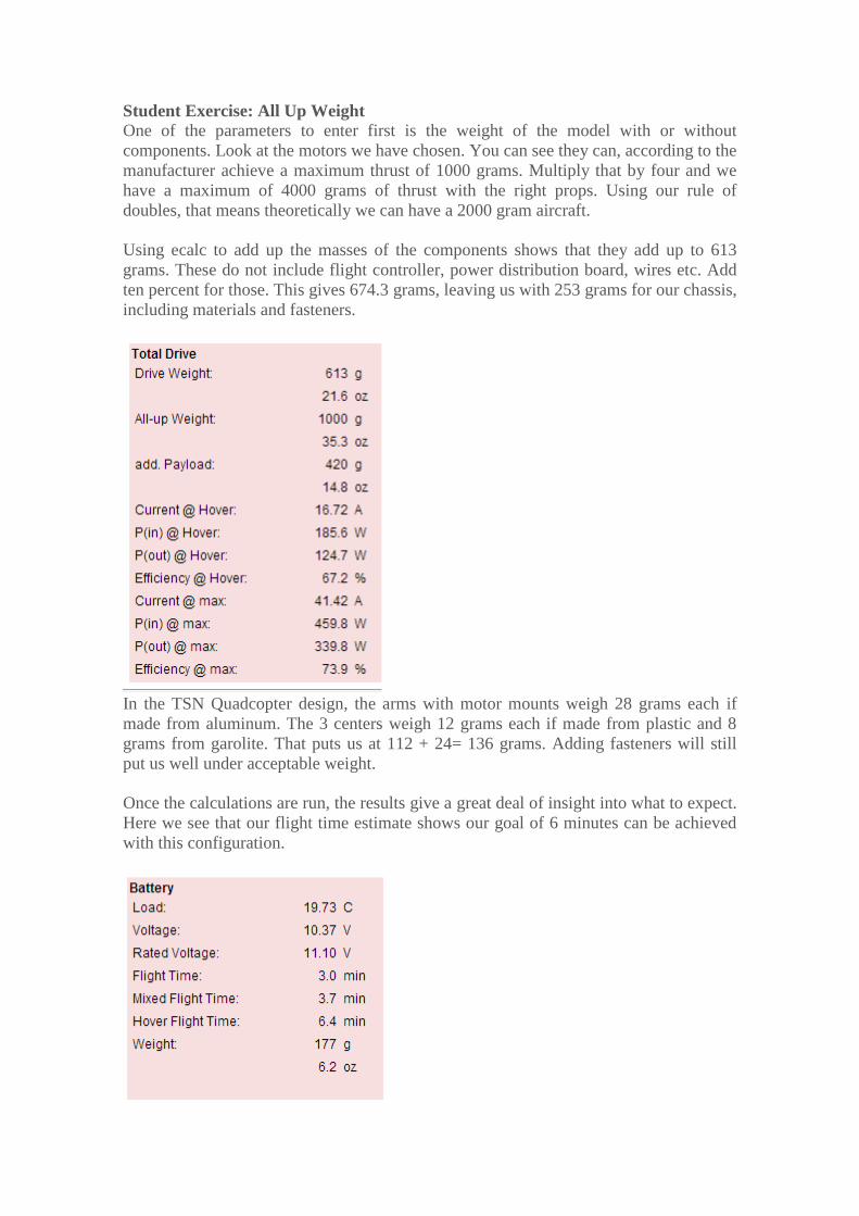
Student Exercise: All Up Weight One of the parameters to enter first is the weight of the model with or without
components. Look at the motors we have chosen. You can see they can, according to the
manufacturer achieve a maximum thrust of 1000 grams. Multiply that by four and we
have a maximum of 4000 grams of thrust with the right props. Using our rule of
doubles, that means theoretically we can have a 2000 gram aircraft.
Using ecalc to add up the masses of the components shows that they add up to 613
grams. These do not include flight controller, power distribution board, wires etc. Add
ten percent for those. This gives 674.3 grams, leaving us with 253 grams for our chassis,
including materials and fasteners.
In the TSN Quadcopter design, the arms with motor mounts weigh 28 grams each if
made from aluminum. The 3 centers weigh 12 grams each if made from plastic and 8
grams from garolite. That puts us at 112 + 24= 136 grams. Adding fasteners will still
put us well under acceptable weight.
Once the calculations are run, the results give a great deal of insight into what to expect.
Here we see that our flight time estimate shows our goal of 6 minutes can be achieved
with this configuration.
There are loads of variables to explore in the data stack generated by ecalc. One
estimates how much extra payload can be carried by the aircraft. If you want to add a
camera, extra battery or retractable landing gear, this figure comes in really handy. In
our example, you can see that we have some room for some goodies with an additional
payload of 420g.
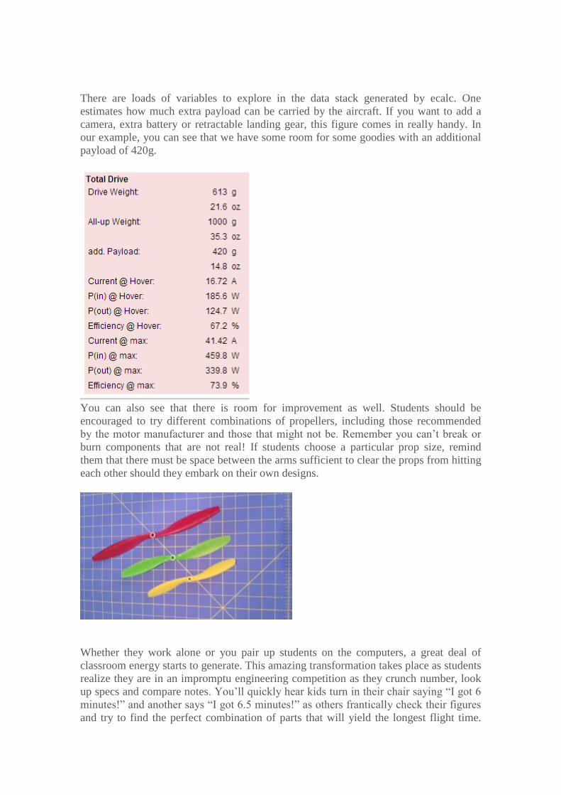
You can also see that there is room for improvement as well. Students should be
encouraged to try different combinations of propellers, including those recommended
by the motor manufacturer and those that might not be. Remember you can’t break or
burn components that are not real! If students choose a particular prop size, remind
them that there must be space between the arms sufficient to clear the props from hitting
each other should they embark on their own designs.
Whether they work alone or you pair up students on the computers, a great deal of
classroom energy starts to generate. This amazing transformation takes place as students
realize they are in an impromptu engineering competition as they crunch number, look
up specs and compare notes. You’ll quickly hear kids turn in their chair saying “I got 6
minutes!” and another says “I got 6.5 minutes!” as others frantically check their figures
and try to find the perfect combination of parts that will yield the longest flight time.
This really gets them excited to start the design a build process! Have students
document several different combinations in their engineering journal so they don’t
forget what works in the simulation. If you have a projector, share out a couple of
combinations that work and some that didn’t for discussion.
Depending on your students’ design skills, they can use software to do some analysis of
different arm designs. They can apply different forces to the arms and see how much
they bend and twist. They will be able to adjust and redistribute mass, material types,
and length of the arms themselves before ever machining a single part. The ‘ready to
manufacture’ design of the TSN Quad is a starting point for teachers and students to get
off the ground. After that, the sky’s the limit.