Embed Size (px)
Citation preview
Materials Science and Engineering A 385 (2004) 212–219
Stress corrosion cracking of stainless steel used in drill collars
N.A. Marianoa,∗, D. Spinellib
a Technologic and Scientific Academic Unit, University S˜ao Francisco, Itatiba, SP 13251-900, Brazilb Engineering School of S˜ao Carlos, University of S˜ao Paulo, S˜ao Carlos, SP 13566-590, Brazil
Received 28 January 2004; received in revised form 7 June 2004
Abstract
The present work, studies the stress corrosion cracking behavior in austenitic Fe–Cr–Mn–N stainless steel, in as received, solubilized andsensitized conditions, submitted to several chlorides environments. To evaluate the stress corrosion cracking susceptibility, double cantileverbeam specimens, fatigue precracked, side grooved and wedge loaded were used. The environments employed were boiling solution of 45 wt.%of MgCl2 at 154◦C and synthetic marine environment at ambient and boiling temperature. The susceptibility to stress corrosion crackinghas been evaluated in terms of the corrosion stress intensity limit factor,KISCC, applying the fracture-mechanics concept. The results showedt the boilingsr©
K
1
dtitts
tcrrtm
s
esis-um
su-
el-s theerec andosive
icalof thedrill
pres-sive
are
thatstress,tibil-
0d
hat only the specimens in the as received and sensitized conditions, were susceptible to the stress corrosion cracking effect inolution of 45 wt.% of MgCl2 at 154◦C, and mean values of the stress corrosion intensity limit factor,KISCC, of 15 MPa
√m and 7.8 MPa
√m,
espectively.2004 Elsevier B.V. All rights reserved.
eywords: Stress corrosion cracking; Chloride; Austenitic stainless steel
. Introduction
The scarcity of nickel during World War II led to theevelopment of new stainless steel alloys with nickel con-
ent lower than normal. The first partial substitute of nickeln the steels of the austenitic group was manganese. Sincehen, studies focusing on the austenitic stainless steels ofhe iron–chromium–manganese–nitrogen system have inten-ified[1,2].
Several free nickel alloys have been developed as substi-utes for the conventional austenitic stainless steel used inryogenic environments and services and in applications thatequire good corrosion resistance. These developments haveesulted in the partial replacement of nickel and the reduc-ion of chromium from 18 to 13 wt.%, with the addition ofanganese and nitrogen.The manganese content of around 11 wt.% increases the
olubility of nitrogen in solution, reducing the nickel content
∗ Corresponding author.E-mail address:[email protected] (N.A. Mariano).
required, but it does not provide the same corrosion rtance effects as nickel and chromium; therefore, a minimamount of nickel must remain in the alloy’s composition (ually less than 5.0 wt.%)[3].
The measuring while drilling (MWD) system was devoped to determine the parameters of oil drilling, such aazimuth, which guides the tool’s face in deep drilling, whservice conditions require materials that are nonmagnetiresistant to both static and dynamic loads, such as correnvironments[4,5].
Because of their excellent combination of mechanproperties and corrosion resistance, the stainless steelsFe–Cr–Mn–N system are used in the manufacture ofcollars, mainly for offshore platforms[6]. Therefore, it isnecessary to understand these steels’ behavior in theence of corrosion caused by their interaction with corroenvironments and the mechanical loads to which theysubjected.
Stress corrosion cracking (SCC) is a failure processoccurs because of the simultaneous presence of tensilean environment and a susceptible material. The suscep
921-5093/$ – see front matter © 2004 Elsevier B.V. All rights reserved.oi:10.1016/j.msea.2004.06.041

N.A. Mariano, D. Spinelli / Materials Science and Engineering A 385 (2004) 212–219 213
ity of these steels to stress corrosion cracking is determinedby imposing stresses on test specimens and determining thetime elapsed for cracks to propagate in a given environment.The failure time increases as the severity of imposed stress de-creases; thus, stress values should be imposed until such timewhen no failure occurs, thereby determining the maximumstress value that can be applied to prevent crack propagationby SCC[7,8].
The purpose of this work is to study the behavior of a stain-less steel of the Fe–Cr–Mn–N system, from the standpoint ofits susceptibility to stress corrosion, in an aqueous solutioncontaining 45 wt.% of MgCl2 at the temperature of boilingand a synthetic marine environment at ambient and boilingtemperature, applying the fracture-mechanics concept of thestress intensity limit factor,KISCC.
2. Experimental procedure
The stainless steel in question belongs to the Fe–Cr–Mn–Nsystem and was supplied in the form of a tube having a diam-eter of 150 mm and wall thickness of 50 mm, from which thespecimens for testing were taken. This steel is convention-ally produced by warm forging at 500–600◦C followed bycooling in air in order to obtain high levels of yield strengthand tensile strength. The steel’s chemical composition, inp
ived,s i-l esec can-n eterswt
ethodo rtingw ial ast .% ofM n-v tsw ation
TT
CCMNNMSNCCPVA
Fig. 1. Double cantilever beam (DCB) type test specimen with lateralnotches machined. Dimensions in millimeter.
plane in an R-L orientation, as shown inFig. 1. The speci-mens were previously fatigue precracked under a sinusoidalwave withR= 0.1, at a frequency of 20Hz, under controlledload. The variation in applied stress intensity,�K, rangedfrom 13 to 15 MPa
√m. The load produced by inserting the
wedge,Po, placed at a distanceao from the tip of the crackto the wedge, was calculated by[12,13]:
2aoPo = P1(3a1 − ao) (1)
where:ao = distance from the tip of the crack to the wedge;Po = load applied by the wedge;P1 = load applied by thetraction machine on the load line;a1 = distance between thetip of the crack and the center of load application.
The values of the initial stress intensity factor,KIO, andthe corrosion stress intensity limit factor,KISCC, were cal-culated byEqs. (1) and (2), based on the value of appliedload measured by the traction machine,P1, on the arms ofthe test specimen along the load line. The exponent 0.577 is acorrection factor for laterally notched test specimens[11,14].
KI = Poao(2√
3 + 2.38H/ao)
BH3/2
[B
Bn
]0.577
(2)
where:KI = stress intensity factor;ao = distance from the tipof the crack to the wedge;Po = load applied by the wedge;H= half of the test specimen’s height;B = thickness of the tests
owthr fac-t el asrt ut lat-e ando ys-t hem der as h re-v hus,i pre-c ckingt nify-i ctor,K ated
ercentage of weight, is given inTable 1.The steel was studied under the conditions of as rece
ensitized at 650◦C for 5 h and cooled slowly and solubized at 1100◦C for 1 h and quenched in water. Under thonditions, the steel’s microstructure was evaluated by sing electron microscopy and its main mechanical paramere determined at ambient temperature and at 150◦C (SCC
esting temperature).The stress corrosion tests performed based to the m
f constant displacement, which is produced by inseedges with varying thickness, made of the same mater
he specimens. The environments employed were 45 wtgCl2 at boiling temperature[9] and a synthetic marine e
ironment at ambient and boiling temperature[10]. The tespecimens were double cantilever beam (DCB) type[11],ith lateral notches machined along the crack propag
able 1he steel’s chemical composition, in percentage of weight
0.04r 13.2n 16.7
0.22i 2.24
0.50i 0.35b 0.21u 0.08o 0.04
0.030.02
l –
pecimen;Bn = effective thickness of the test specimen.Tests were also performed to determine the crack gr
ate (da/dt) as a function of the applied stress intensityor, KI , on DCB type test specimens of the stainless steeceived and in the solution of 45 wt.% of MgCl2 at boilingemperature. The test specimens were machined withoral notching to facilitate reading of the crack lengths,ptically monitored with the help of a magnifying glass s
em with micrometric meter with 0.01 mm precision. Teasurements were compared with readings taken un
tereoscopic microscope with a micrometric table, whicealed a variation of less than 1% between readings. Tn order to normalize the measuring procedure of bothracks and crack propagation in the stress corrosion craests, we decided to use the readings taken with the magng glass system. The variation of the stress intensity fa
I , as a function of the crack’s growth rate, was calcul
214 N.A. Mariano, D. Spinelli / Materials Science and Engineering A 385 (2004) 212–219
throughEq. (3), since the constant displacement method wasused in these tests, the value ofKI could not be determinedusing the instant load value[11,14].
KI = EVH√
3H(a + 0.6)2 + H3
4[(a + 0.6H)3 + H2a]
[B
Bn
]0.577
(3)
where:K1 = stress intensity factor;E = modulus of elastic-ity (or Young’s modulus);a = crack length;V = displace-ment of the test specimen’s arm produced by inserting awedge;H = half of the test specimen’s height;B = thick-ness of the test specimen;Bn = effective thickness of the testspecimen.
Fat
The test specimens were left in the environments studiedfor periods varying from 15 to 90 days and, at the end of thetests, the wedges were removed with the help of a tractionmachine in order to obtain the final load measured midwayalong the load line. The test specimens after fracture were re-moved, washed with methanol in an ultrasonic cleaning anddried. Then, using a stereoscopic microscope, measurementswere taken of the distances between the position where thewedge was placed and the end of the pre-crack and the crackproduced by stress corrosion in three positions, at 25%Bn;50%Bn and 75%Bn. The average value of these measure-ments was then adopted as the length of the initial and finalcrack, respectively, used in the calculation of the initial stressintensity factor,KIO, and of the corrosion stress intensity limitfactor,KISCC.
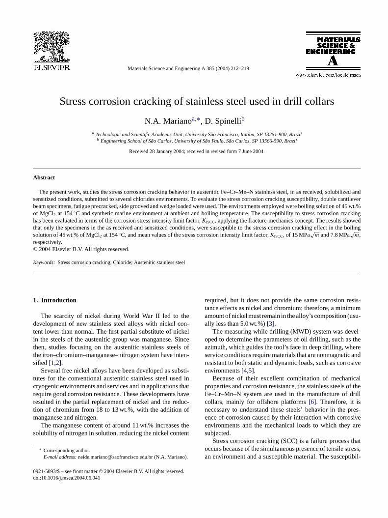
ig. 2. SEM micrograph of the as received steel: (a) reveals a completelyustenitic microstructure and (b) regions that did not recrystallized due to
he mechanical forging process.
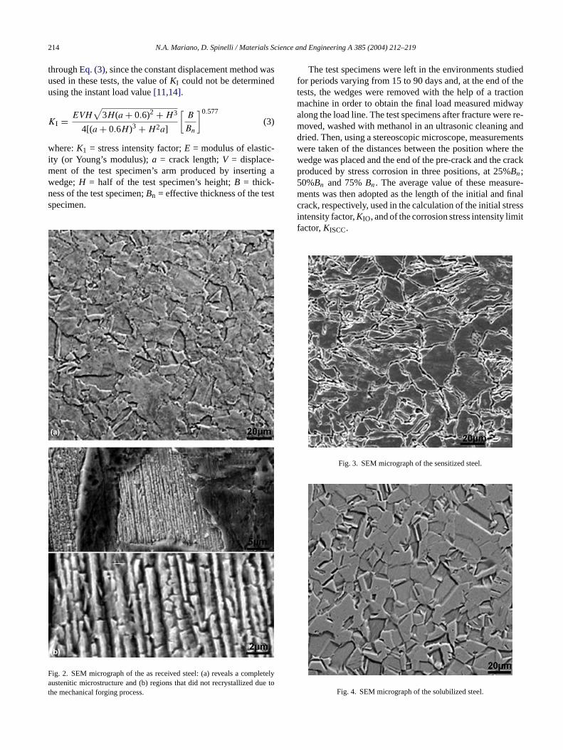
Fig. 3. SEM micrograph of the sensitized steel.
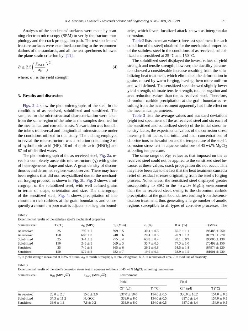
Fig. 4. SEM micrograph of the solubilized steel.
N.A. Mariano, D. Spinelli / Materials Science and Engineering A 385 (2004) 212–219 215
Analyses of the specimens’ surfaces were made by scan-ning electron microscopy (SEM) to verify the fracture mor-phology and the crack propagation path. The test specimens’fracture surfaces were examined according to the recommen-dations of the standards, and all the test specimens followedthe plane strain criterion by:[11].
B ≥ 2.5
(KISCC
σE
)2
(4)
where:σE is the yield strength.
3. Results and discussion
Figs. 2–4show the photomicrographs of the steel in theconditions of as received, solubilized and sensitized. Thesamples for the microstructural characterization were takenfrom the same region of the tube as the samples destined forthe mechanical and corrosion tests. No variation was found inthe tube’s transversal and longitudinal microstructure underthe conditions utilized in this study. The etching employedto reveal the microstructure was a solution containing 3 mlof hydrofluoric acid (HF), 10 ml of nitric acid (HNO3) and87 ml of distilled water.
vo scon-t haveb hani-c -c insi rapho ec nse-q nd-
TE
S MPa)
A ± 5A ± 6S ± 4S ± 3S ± 6S ± 7
σ otal elo
TE lutions
S Enviro
Initial
Cl− (g
A 337.0S 338S 338.
aries, which favors localized attack known as intergranularcorrosion.
Table 2lists the mean values (three test specimens for eachcondition of the steel) obtained for the mechanical propertiesof the stainless steel in the conditions of as received, solubi-lized and sensitized at 25◦C and 150◦C.
The solubilized steel displayed the lowest values of yieldstrength and tensile strength, however, the ductility parame-ters showed a considerable increase resulting from the solu-bilizing heat treatment, which eliminated the deformation ingrains caused by warm forging, leaving them more uniformand well defined. The sensitized steel showed slightly loweryield strength, ultimate tensile strength, total elongation andarea reduction values than the as received steel. Therefore,chromium carbide precipitation at the grain boundaries re-sulting from the heat treatment apparently had little effect onthe mechanical parameters.
Table 3lists the average values and standard deviations(eight test specimens of the as received steel and six each ofthe sensitized and solubilized steels) of the initial stress in-tensity factor, the experimental values of the corrosion stressintensity limit factor, the initial and final concentrations ofchlorine ions in the solution and the temperature of the steel’scorrosion stress test in aqueous solutions of 45 wt.% MgCl2at boiling temperature.
asr el be-c . Thism used ar ingp reaters tt rbidep nsi-t odicr . The
The photomicrograph of the as received steel,Fig. 2a, re-eals a completely austenitic microstructure (�) with grainsf heterogeneous shape and size. A great density of di
inuous and deformed regions was observed. These mayeen regions that did not recrystallized due to the mecal forging process, as shown inFig. 2b. Fig. 3shows a mirograph of the solubilized steel, with well defined gran terms of shape, orientation and size. The microgf the sensitized steel,Fig. 4, shows precipitation of finhromium rich carbides at the grain boundaries and couently a chromium poor matrix adjacent to the grain bou
able 2xperimental results of the stainless steel’s mechanical properties
tainless steel T (◦C) σE (MPa) σR (
s received 25 790± 7 899s received 150 683± 8 748olubilized 25 344± 3 775olubilized 150 245± 5 569ensitized 25 740± 8 865ensitized 150 572± 8 682
E = yield strength measured at 0.2% of strain;σR = tensile strength;εt = t
able 3xperimental results of the steel’s corrosion stress test in aqueous so
tainless steel KIO (MPa√
m) KISCC (MPa√
m)
s received 23.0± 2.0 15.0± 2.0olubilized 37.3± 11.2 No SCCensitized 38.6± 1.3 7.8± 0.2
εt (%) R.A. (%) E (MPa)
30.4 ± 0.3 65.7 ± 1.1 196488± 25020.4 ± 0.5 70.9 ± 1.3 189790± 27063.8 ± 0.4 70.1 ± 0.9 196006± 13035.7 ± 0.5 77.3 ± 1.0 170492± 15029.2 ± 0.8 64.5 ± 1.8 187974± 22019.6 ± 0.5 68.9 ± 1.5 181901± 230
ngation; R.A. = reduction of area;E = modulus of elasticity.
of 45 wt.% MgCl2 at boiling temperature
nment
Final
/l) T (oC) Cl− (g/l) T (oC)
± 10.0 154.0± 0.5 336.0± 10.2 154.0± 0.5.0± 8.0 154.0± 0.5 337.0± 8.4 154.0± 0.50± 8.0 154.0± 0.5 337.0± 8.4 154.0± 0.5
The same range ofKIO values as that imposed on theeceived steel could not be applied to the sensitized steause, at these values, crack propagation did not occuray have been due to the fact that the heat treatment ca
elief of residual stresses originating from the steel’s forgrocess. Nonetheless, the sensitized steel displayed gusceptibility to SSC in the 45 wt.% MgCl2 environmenhan the as received steel, owing to the chromium carecipitation at the grain boundaries resulting from the se
ization treatment, thus generating a large number of anegions susceptible to all types of corrosive processes
216 N.A. Mariano, D. Spinelli / Materials Science and Engineering A 385 (2004) 212–219
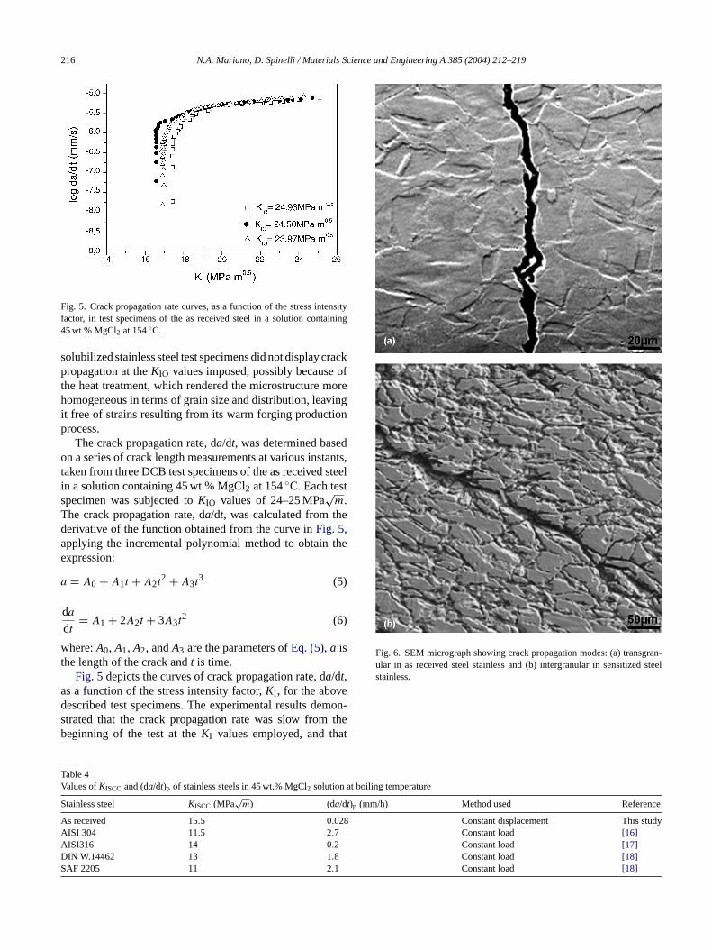
Fig. 5. Crack propagation rate curves, as a function of the stress intensityfactor, in test specimens of the as received steel in a solution containing45 wt.% MgCl2 at 154◦C.
solubilized stainless steel test specimens did not display crackpropagation at theKIO values imposed, possibly because ofthe heat treatment, which rendered the microstructure morehomogeneous in terms of grain size and distribution, leavingit free of strains resulting from its warm forging productionprocess.
The crack propagation rate, da/dt, was determined basedon a series of crack length measurements at various instants,taken from three DCB test specimens of the as received steelin a solution containing 45 wt.% MgCl2 at 154◦C. Each testspecimen was subjected toKIO values of 24–25 MPa
√m.
The crack propagation rate, da/dt, was calculated from thederivative of the function obtained from the curve inFig. 5,applying the incremental polynomial method to obtain theexpression:
a = A0 + A1t + A2t2 + A3t
3 (5)
da
dt= A1 + 2A2t + 3A3t
2 (6)
where:A0, A1, A2, andA3 are the parameters ofEq. (5), a isthe length of the crack andt is time.
Fig. 5depicts the curves of crack propagation rate, da/dt,as a function of the stress intensity factor,KI , for the abovedescribed test specimens. The experimental results demon-s theb at
TV at boiling temperature
S )p (mm/h) Method used Reference
A Constant displacement This studyA Constant load [16]A Constant load [17]D Constant load [18]S Constant load [18]
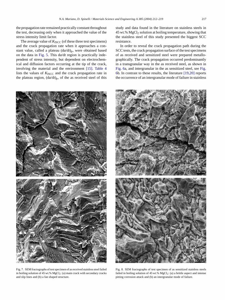
Fig. 6. SEM micrograph showing crack propagation modes: (a) transgran-ular in as received steel stainless and (b) intergranular in sensitized steelstainless.
trated that the crack propagation rate was slow fromeginning of the test at theKI values employed, and th
able 4alues ofKISCC and (da/dt)p of stainless steels in 45 wt.% MgCl2 solution
tainless steel KISCC (MPa√
m) (da/dt
s received 15.5 0.028ISI 304 11.5 2.7ISI316 14 0.2IN W.14462 13 1.8AF 2205 11 2.1
N.A. Mariano, D. Spinelli / Materials Science and Engineering A 385 (2004) 212–219 217
the propagation rate remained practically constant throughoutthe test, decreasing only when it approached the value of thestress intensity limit factor.
The average value ofKISCC(of these three test specimens)and the crack propagation rate when it approaches a con-stant value, called a plateau (da/dt)p, were obtained basedon the data inFig. 5. This da/dt region is practically inde-pendent of stress intensity, but dependent on electrochem-ical and diffusion factors occurring at the tip of the crack,involving the material and the environment[15]. Table 4lists the values ofKISCC and the crack propagation rate inthe plateau region, (da/dt)p, of the as received steel of this
Fia
study and data found in the literature on stainless steels in45 wt.% MgCl2 solution at boiling temperature, showing thatthe stainless steel of this study presented the biggest SCCresistance.
In order to reveal the crack propagation path during theSCC tests, the crack propagation surface of the test specimensof as received and sensitized steel were prepared metallo-graphically. The crack propagation occurred predominantlyin a transgranular way in the as received steel, as shown inFig. 6a, and intergranular in the as sensitized steel, seeFig.6b. In contrast to these results, the literature[19,20] reportsthe occurrence of an intergranular mode of failure in stainless
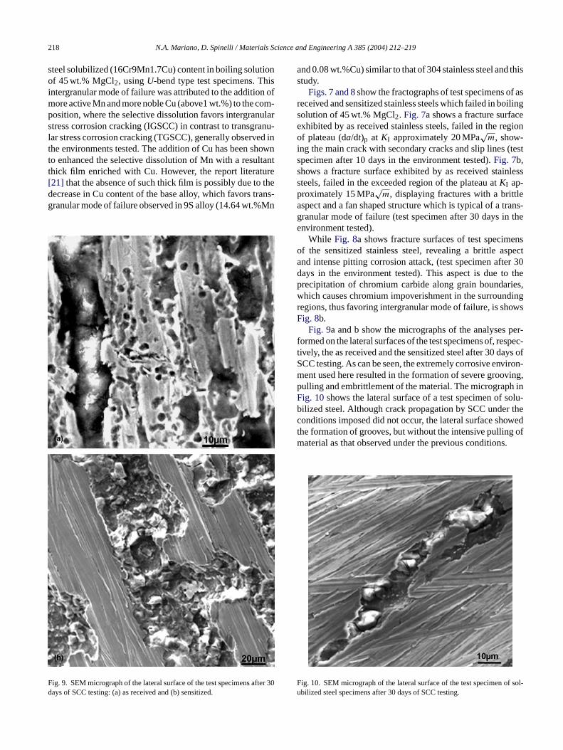
ig. 7. SEM fractographs of test specimen of as received stainless steel failedn boiling solution of 45 wt.% MgCl2: (a) main crack with secondary cracksnd slip lines and (b) a fan shaped structure.
Ffp
ig. 8. SEM fractographs of test specimen of as sensitized stainless steelsailed in boiling solution of 45 wt.% MgCl2: (a) a brittle aspect and intenseitting corrosion attack and (b) an intergranular mode of failure.
218 N.A. Mariano, D. Spinelli / Materials Science and Engineering A 385 (2004) 212–219
steel solubilized (16Cr9Mn1.7Cu) content in boiling solutionof 45 wt.% MgCl2, usingU-bend type test specimens. Thisintergranular mode of failure was attributed to the addition ofmore active Mn and more noble Cu (above1 wt.%) to the com-position, where the selective dissolution favors intergranularstress corrosion cracking (IGSCC) in contrast to transgranu-lar stress corrosion cracking (TGSCC), generally observed inthe environments tested. The addition of Cu has been shownto enhanced the selective dissolution of Mn with a resultantthick film enriched with Cu. However, the report literature[21] that the absence of such thick film is possibly due to thedecrease in Cu content of the base alloy, which favors trans-granular mode of failure observed in 9S alloy (14.64 wt.%Mn
Fd
and 0.08 wt.%Cu) similar to that of 304 stainless steel and thisstudy.
Figs. 7 and 8show the fractographs of test specimens of asreceived and sensitized stainless steels which failed in boilingsolution of 45 wt.% MgCl2. Fig. 7a shows a fracture surfaceexhibited by as received stainless steels, failed in the regionof plateau (da/dt)p at KI approximately 20 MPa
√m, show-
ing the main crack with secondary cracks and slip lines (testspecimen after 10 days in the environment tested).Fig. 7b,shows a fracture surface exhibited by as received stainlesssteels, failed in the exceeded region of the plateau atKI ap-proximately 15 MPa
√m, displaying fractures with a brittle
aspect and a fan shaped structure which is typical of a trans-granular mode of failure (test specimen after 30 days in theenvironment tested).
While Fig. 8a shows fracture surfaces of test specimensof the sensitized stainless steel, revealing a brittle aspectand intense pitting corrosion attack, (test specimen after 30days in the environment tested). This aspect is due to theprecipitation of chromium carbide along grain boundaries,which causes chromium impoverishment in the surroundingregions, thus favoring intergranular mode of failure, is showsFig. 8b.
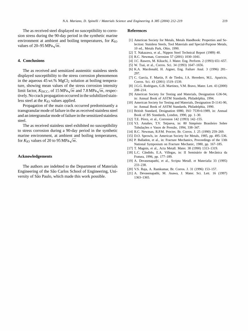
Fig. 9a and b show the micrographs of the analyses per-formed on the lateral surfaces of the test specimens of, respec-t ys ofS iron-m ving,p h inF olu-b r thec wedt ofm .
ig. 9. SEM micrograph of the lateral surface of the test specimens after 30ays of SCC testing: (a) as received and (b) sensitized.
F f sol-u
ively, the as received and the sensitized steel after 30 daCC testing. As can be seen, the extremely corrosive envent used here resulted in the formation of severe grooulling and embrittlement of the material. The micrograpig. 10shows the lateral surface of a test specimen of silized steel. Although crack propagation by SCC undeonditions imposed did not occur, the lateral surface shohe formation of grooves, but without the intensive pullingaterial as that observed under the previous conditions
ig. 10. SEM micrograph of the lateral surface of the test specimen obilized steel specimens after 30 days of SCC testing.
N.A. Mariano, D. Spinelli / Materials Science and Engineering A 385 (2004) 212–219 219
The as received steel displayed no susceptibility to corro-sion stress during the 90-day period in the synthetic marineenvironment at ambient and boiling temperatures, forKIOvalues of 20–95 MPa
√m.
4. Conclusions
The as received and sensitized austenitic stainless steelsdisplayed susceptibility to the stress corrosion phenomenonin the aqueous 45 wt.% MgCl2 solution at boiling tempera-ture, showing mean values of the stress corrosion intensitylimit factor, KISCC, of 15 MPa
√m and 7.8 MPa
√m, respec-
tively. No crack propagation occurred in the solubilized stain-less steel at theKIO values applied.
Propagation of the main crack occurred predominantly atransgranular mode of failure in the as received stainless steeland an intergranular mode of failure in the sensitized stainlesssteel.
The as received stainless steel exhibited no susceptibilityto stress corrosion during a 90-day period in the syntheticmarine environment, at ambient and boiling temperatures,for KIO values of 20 to 95 MPa
√m.
A
rialsE ni-v
References
[1] American Society for Metals, Metals Handbook: Properties and Se-lection: Stainless Steels, Tool Materials and Special-Purpose Metals,10 ed., Metals Park, Ohio, 1990.
[2] T. Nakazawa, et al., Nippon Steel Technical Report (1989) 40.[3] R.C. Newman, Corrosion 57 (2001) 1030–1041.[4] J.C. Rawers, M. Kikuchi, J. Mater. Eng. Perform. 2 (1993) 651–657.[5] W. Tsai, et al., Corros. Sci. 34 (1993) 1647–1656.[6] K.A. Macdonald, H. Aigner, Eng. Failure Anal. 3 (1996) 281–
297.[7] C. Garcıa, F. Martın, P. de Tiedra, J.A. Heredero, M.L. Aparicio,
Corros. Sci. 43 (2001) 1519–1539.[8] J.G.G. Rodrigues, G.B. Martinez, V.M. Bravo, Mater. Lett. 43 (2000)
208–214.[9] American Society for Testing and Materials, Designation G36-94,
in: Annual Book of ASTM Standards, Philadelphia, 1994.[10] American Society for Testing and Materials, Designation D-1141-90,
in: Annual Book of ASTM Standards, Philadelphia, 1990.[11] British Standard, Designation 6980, ISO 7539-6:1989, in: Annual
Book of BS Standards, London, 1990, pp. 1–30.[12] T.E. Perez, et al., Corrosion 142 (1993) 142–155.[13] V.I. Astafiev, T.V. Tetjueva, in: 80 Simposio Brasileiro Sobre
Tubulacoes e Vasos de Pressao, 1994, 338–347.[14] R.C. Newman, R.P.M. Procter, Br. Corros. J. 25 (1990) 259–269.[15] D.O. Sprowls, in: American Society for Metals, 1985, pp. 495–536.[16] P. Balladon, et al., in: Fracture Mechanics, Proceedings of the 13th
National Symposium on Fracture Mechanic, 1980, pp. 167–185.[17] T. Magnin, et al., Acta Metall. Mater. 38 (1990) 1313–1319.[18] L.C. Candido, E.A. Villegas, in: II Seminario de Mecanica da
[ 995)
[[ 97)
cknowledgements
The authors are indebted to the Department of Matengineering of the Sao Carlos School of Engineering, Uersity of Sao Paulo, which made this work possible.
Fratura, 1996, pp. 177–189.19] A. Devasenapathi, et al., Scripta Metall. et Materialia 33 (1
233–238.20] V.S. Raja, A. Ramkumar, Br. Corros. J. 31 (1996) 153–157.21] A. Devasenapathi, M. Asawa, J. Mater. Sci. Lett. 16 (19
1363–1365.