Embed Size (px)
Citation preview
ORIGINAL ARTICLE
Received September 16, 2021 In revised form September 22, 2021 Accepted September 22, 2021 Available online September 27, 2021. https://doi.org/10.1590/1679-78256740
Latin American Journal of Solids and Structures. ISSN 1679-7825. Copyright © 2021. This is an Open Access article distributed under the terms of the Creative Commons Attribution License, which permits unrestricted use, distribution, and reproduction in any medium, provided the original work is properly cited.
Latin American Journal of Solids and Structures, 2021, 18(7), e405 1/18
Stress Transferring Mechanism of a Pressure Tunnel Lining Strengthened with CFRP
Gan Qina,b , Fan Yangc* , Dianqi Jina
a Shenzhen Urban Public Safety and Technology Institute, Shenzhen Guangdong 518046, China. E-mail: [email protected], [email protected] b School of Civil and Environmental Engineering, Harbin Institute of Technology (Shenzhen), Shenzhen Guangdong 518055, China. c School of Civil and Hydraulic Engineering, Hefei University of Technology, Hefei Anhui 230009, China. E-mail: [email protected]
* Corresponding author
https://doi.org/10.1590/1679-78256740
Abstract This paper investigates the stress transferring mechanism of a pressure tunnel strengthened with CFRP. A simplified mechanical model of the internal water pressure transfer from the CFRP to the lining concrete is established, and the key parameters that influence the internal water pressure transfer between the CFRP and lining concrete are identified. A solid-spring-solid three-dimensional finite element model is established. Using the numerical model, the influences of the above key parameters on the ratios of the internal water pressure borne by the concrete and CFRP are investigated. Based on the above results, a reinforcement scheme of the Yellow River Crossing Tunnel is studied and optimized as a case study. This reveals that the elastic modulus and thickness of the CFRP are the two most important factors that affect the ratios of the internal water pressure borne by the concrete and CFRP, and increasing the elastic modulus and thickness of the CFRP can decrease the ratio of the internal water pressure borne by the concrete and improve the stress state of the lining concrete.
Keywords Pressure tunnel; CFRP, Stress transferring mechanism; Bearing ratio; Yellow River Crossing Tunnel; Finite element analysis
Graphical Abstract
60
70
80
90
100
100 200 300 400 500 600坐标轴标题
1 layer of CFRP
2 layers of CFRP
3 layers of CFRP
4 layers of CFRP
Bea
ring
ratio
ofc
oncr
ete
/ %
Elastic modulus of CFRP (Ec) / GPa
60
70
80
90
100
0.5 1 1.5 2 2.5 3 3.5 4坐标轴标题
1 layer of CFRP
2 layers of CFRP
3 layers of CFRP
4 layers of CFRP
Bea
ring
ratio
of c
oncr
ete
/ %
Thickness of adhesive (ta) / mm
0
20
40
60
80
100
0 0.5 1 1.5 2坐标轴标题
1 layer of CFRP
2 layers of CFRP
3 layers of CFRP
4 layers of CFRP
Bea
ring
ratio
of c
oncr
ete
/ %
Thickness of CFRP (tc) / mm
60
70
80
90
100
100 200 300 400 500 600坐标轴标题
1 layer of CFRP
2 layers of CFRP
3 layers of CFRP
4 layers of CFRP
Bea
ring
ratio
ofc
oncr
ete
/ %
Elastic modulus of CFRP (Ec) / GPa
CFRP
Finite element model
Concrete
Rebar
Uncracked
Cracked
Uncracked
Cracked
(a) (b)
Stress Transferring Mechanism of a Pressure Tunnel Lining Strengthened with CFRP Gan Qin
Latin American Journal of Solids and Structures, 2021, 18(7), e405 2/18
1 INTRODUCTION
Currently, a large number of water conveyance tunnels in many countries have been in operation for decades. However, due to the influences of many factors (construction errors, earthquakes, material property degradation, etc.), different degrees of damage problems, such as lining cracks and falling chip off leakage, have been found in a considerable number of water conveyance tunnels (Wang et al., 2001; Farhadian et al., 2017; Lai et al., 2017). These problems will affect the stability of the tunnel structure and even seriously endanger the safety of the whole water conveyance project. Therefore, research on the damage of water conveyance tunnels and the related treatment measures have attracted much attention from scholars. Carbon fiber reinforced plastics (CFRPs) have the advantages of a high strength-weight ratio, short installation period, minimal impact on the concrete structure and adaptability to curved surfaces (Sun et al., 2017; Yang et al., 2019; Liu et al., 2020). Since CFRP reinforcement technology can effectively limit the continuous expansion of concrete cracks and prevent the lining from being broken and spalling, it has gradually become a common and effective way to strengthen the internal surface of a pressure tunnel lining (Wang and Lee, 2012; Liu et al., 2014). Taking China as an example, as presented in Table 1, CFRP reinforcement technology has been well applied in many projects, such as the Taohuajiang Reservoir, Qingshan Reservoir, and Dahuofang Reservoir (Li and Liu, 2007; Li et al., 2011; Yang and Gao, 2011).
Table 1 Some pressure tunnels strengthened with CFRP in China
Project Tunnel type Tunnel diameter (mm) Lining thickness (mm) CFRP reinforcement method
Taohuajiang Reservoir Pressure tunnel 1750 300 Stick CFRP on the internal surface Qingshan Reservoir Pressure tunnel 3500 600~1000 Stick CFRP on the internal surface
Dahuofang Reservoir Pressure tunnel 6000 500 Stick CFRP on the internal surface Fengxi Reservoir Pressure tunnel 1800 400 Stick CFRP on the internal surface
Many theoretical and experimental studies have been devoted to investigating the behavior of tunnel linings strengthened with bonded CFRP. He et al. (2009) studied the influence of a cavity in the tunnel vault on the mechanical characteristics of the tunnel lining and discussed the distribution of internal forces and failure forms of a tunnel lining strengthened with CFRP. Yuan and Li (2010) conducted a series of tests to investigate the spalling resistance effect of a tunnel lining strengthened with CFRP and pointed out that sticking CFRP on the internal surface of the lining can effectively prevent the protective layer of the concrete from spalling. Xie et al. (2014) and Chen et al. (2015) investigated the blast resistances of tunnel linings reinforced with CFRP, and the results revealed that CFRP can decrease the area of the concrete in tension and keep more concrete in compression, which can effectively increase the bending rigidity and improve the bearing capacity of the lining. Wang et al. (2018) investigated the dynamic response behaviors of tunnel linings strengthened with CFRP subjected to blast loads and revealed that a CFRP reinforcement scheme can make a significant contribution to decreasing the spalling and cracking of the lining concrete.
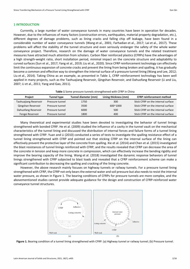
However, the above research mainly focuses on highway tunnels or railway tunnels. For a pressure tunnel lining strengthened with CFRP, the CFRP not only bears the external water and soil pressure but also needs to resist the internal water pressure, as shown in Figure 1. The bearing conditions of CFRPs for pressure tunnels are more complex, and the abovementioned studies cannot provide adequate guidance for the design and construction of CFRP-reinforced water conveyance tunnel structures.
Lining concrete
CFRP Adhesive
Wall rock Wall rock
(a) (b)
Lining concrete
CFRP
Adhesive
Internal waterpressure
Figure 1. Bearing condition of a tunnel lining strengthened with CFRP: (a) Highway tunnel or railway tunnel; (b) Pressure tunnel.
Stress Transferring Mechanism of a Pressure Tunnel Lining Strengthened with CFRP Gan Qin
Latin American Journal of Solids and Structures, 2021, 18(7), e405 3/18
To reveal the CFRP reinforcement effect for pressure water conveyance tunnels, experimental studies on linings strengthened with CFRP subject to uniform internal pressure are conducted to analyze and compare the concrete stresses and deformations before and after reinforcement (Zhang et al., 2005; Wang, 2004). The experimental results indicate that CFRP can clearly prevent concrete cracks from extending further, and it can improve the ultimate bearing capacity of the lining concrete. These studies are helpful to promote the further application of CFRP reinforcement technology for pressure water conveyance tunnels. However, the mechanical characteristics of a CFRP-adhesive-concrete composite structure have not been fully studied. The stress transferring mechanism of this multilayer composite structure subject to the internal water pressure has not been wholly revealed, and the ratio of the internal water pressure borne by each structure is unclear.
To obtain the mechanical characteristics of a CFRP-adhesive-concrete multilayer composite structure subject to the internal water pressure, the processes of the internal water pressure transferred to the lining concrete through the CFRP and adhesive are analyzed. An analytical model for the stress transfer of a CFRP-adhesive-concrete multilayer composite structure is proposed, and the key parameters affecting the stress transfer of the internal water pressure are obtained. In addition, a solid-spring-solid 3D finite element model is established for a pressure water conveyance tunnel strengthened with CFRP. Based on the analytical and numerical results, the influences of the above key parameters on the ratios of the internal water pressure borne by the concrete and CFRP are analyzed, and a parametric study is carried out to increase the bearing efficiency of the CFRP and improve the stress state of the lining concrete. Finally, the above studies are verified by a case study of the Yellow River Crossing Tunnel in China.
2 ANALYTICAL MODEL FOR THE STRESS TRANSFERRING MECHANISM
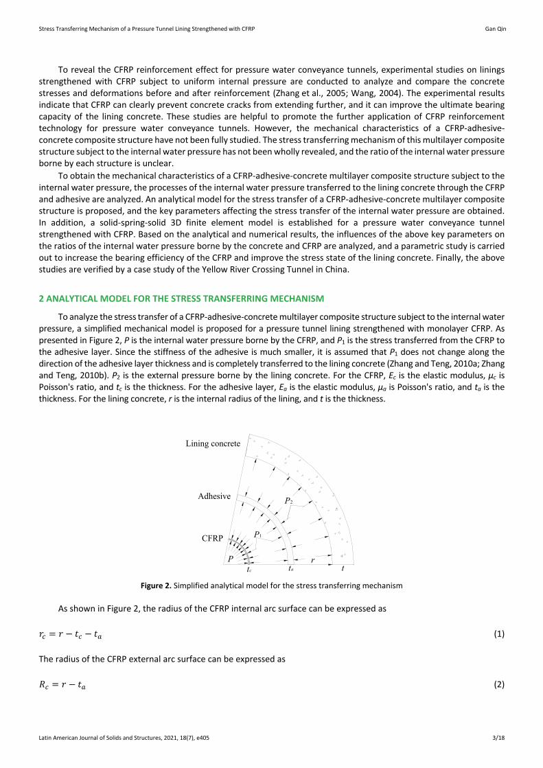
To analyze the stress transfer of a CFRP-adhesive-concrete multilayer composite structure subject to the internal water pressure, a simplified mechanical model is proposed for a pressure tunnel lining strengthened with monolayer CFRP. As presented in Figure 2, P is the internal water pressure borne by the CFRP, and P1 is the stress transferred from the CFRP to the adhesive layer. Since the stiffness of the adhesive is much smaller, it is assumed that P1 does not change along the direction of the adhesive layer thickness and is completely transferred to the lining concrete (Zhang and Teng, 2010a; Zhang and Teng, 2010b). P2 is the external pressure borne by the lining concrete. For the CFRP, Ec is the elastic modulus, µc is Poisson's ratio, and tc is the thickness. For the adhesive layer, Ea is the elastic modulus, µa is Poisson's ratio, and ta is the thickness. For the lining concrete, r is the internal radius of the lining, and t is the thickness.
Lining concrete
Adhesive
CFRP
P
P1
P2
tc ta tr
Figure 2. Simplified analytical model for the stress transferring mechanism
As shown in Figure 2, the radius of the CFRP internal arc surface can be expressed as
𝑟𝑟𝑐𝑐 = 𝑟𝑟 − 𝑡𝑡𝑐𝑐 − 𝑡𝑡𝑎𝑎 (1)
The radius of the CFRP external arc surface can be expressed as
𝑅𝑅𝑐𝑐 = 𝑟𝑟 − 𝑡𝑡𝑎𝑎 (2)
Stress Transferring Mechanism of a Pressure Tunnel Lining Strengthened with CFRP Gan Qin
Latin American Journal of Solids and Structures, 2021, 18(7), e405 4/18
According to the Lame formula, the circumferential stress of the CFRP external surface can be calculated by
𝜎𝜎𝜃𝜃 = 𝑟𝑟𝑐𝑐2(𝑃𝑃−𝑃𝑃1)𝑅𝑅𝑐𝑐2−𝑟𝑟𝑐𝑐2
+ 𝑃𝑃𝑟𝑟𝑐𝑐2−𝑃𝑃1𝑅𝑅𝑐𝑐2
𝑅𝑅𝑐𝑐2−𝑟𝑟𝑐𝑐2 (3)
According to the physical equation of the plane stress problem, the circumferential strain of the CFRP external surface can be obtained by
𝜀𝜀𝜃𝜃 = 𝜎𝜎𝜃𝜃𝐸𝐸𝑐𝑐
+ 𝜇𝜇𝑐𝑐𝑃𝑃1𝐸𝐸𝑐𝑐
(4)
According to the geometric equation of the plane stress problem and in the absence of higher-order terms, the radial displacement of the CFRP external surface can be expressed as
∆= 𝜀𝜀𝜃𝜃𝑅𝑅𝑐𝑐 (5)
Since the elastic modulus of the adhesive is much smaller than that of the concrete, the concrete can be considered a rigid material, and the adhesive layer can be considered a flexible material. Therefore, the compression deformation of the adhesive layer can be assumed to be equal to the radial displacement of the CFRP external surface, and the stress transferred to the concrete through the adhesive layer can be expressed as
𝑃𝑃2 = 𝑃𝑃1 = 𝐸𝐸𝑎𝑎∆𝑡𝑡𝑎𝑎
(6)
Substituting Equations 4, 5 and 6 into Equation 3, the following equation can be obtained.
� 2𝑟𝑟𝑐𝑐2𝑃𝑃�𝑅𝑅𝑐𝑐2−𝑟𝑟𝑐𝑐2�𝑃𝑃1
− 𝑟𝑟𝑐𝑐2+𝑅𝑅𝑐𝑐2
𝑅𝑅𝑐𝑐2−𝑟𝑟𝑐𝑐2+ 𝜇𝜇𝑐𝑐�
𝐸𝐸𝑎𝑎𝑅𝑅𝑐𝑐𝑡𝑡𝑎𝑎𝐸𝐸𝑐𝑐
= 1 (7)
Substituting Equations 1 and 2 into Equation 7, the following equation can be obtained.
� 2(𝑟𝑟−𝑡𝑡𝑐𝑐−𝑡𝑡𝑎𝑎)2
(𝑟𝑟−𝑡𝑡𝑎𝑎)2−(𝑟𝑟−𝑡𝑡𝑐𝑐−𝑡𝑡𝑎𝑎)2𝑃𝑃𝑃𝑃1− (𝑟𝑟−𝑡𝑡𝑐𝑐−𝑡𝑡𝑎𝑎)2+(𝑟𝑟−𝑡𝑡𝑎𝑎)2
(𝑟𝑟−𝑡𝑡𝑎𝑎)2−(𝑟𝑟−𝑡𝑡𝑐𝑐−𝑡𝑡𝑎𝑎)2 + 𝜇𝜇𝑐𝑐�𝐸𝐸𝑎𝑎(𝑟𝑟−𝑡𝑡𝑎𝑎)𝑡𝑡𝑎𝑎𝐸𝐸𝑐𝑐
= 1 (8)
As seen from Equation 8, when the radius of the lining concrete (r) is determined, the stress transferred from the CFRP to the concrete (P1) can only be influenced by Ec, μc, tc, Ea and ta. Therefore, the above five key parameters can determine the ratio of the stress transmitted to the concrete and then determine the stress states of the CFRP and lining concrete.
Since the above derivation process of the formulas is somewhat simplified, for example, the concrete and adhesive layer is simplified as a linear elastic material, and the bonding slip between the adhesive layer and the lining concrete is ignored, Equation 8 can only roughly reveal that the above five key parameters can affect the ratios of the internal water pressure borne by the concrete and CFRP. However, there are many types of CFRP, such as low elastic modulus CFRP, standard elastic modulus CFRP, and high elastic modulus CFRP, etc. In addition, there are various adhesive layers commonly used in engineering, and the mechanical properties such as tensile strength, elastic modulus and elongation of different adhesive layers are also different. Therefore, it is necessary to further study the effects of the variations of the above parameters on the ratios of the internal water pressure borne by the concrete and CFRP. Since experimental tests have high requirements for the equipment and costs, numerical simulations become efficient methods to further study engineering cases, and the degrees of the actual influences of the above five parameters on the ratio of the stress transferred to the concrete are emphatically discussed.
Stress Transferring Mechanism of a Pressure Tunnel Lining Strengthened with CFRP Gan Qin
Latin American Journal of Solids and Structures, 2021, 18(7), e405 5/18
3 THREE-DIMENSIONAL NUMERICAL SIMULATION
3.1 Experimental model
3.1.1 Specimen parameters
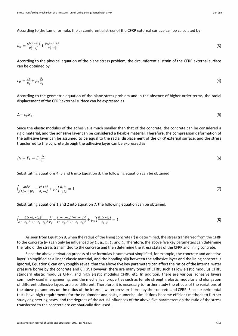
An experimental test is conducted for a pressure tunnel lining strengthened with CFRP (Wang, 2004). As presented in Figure 3, the tunnel lining is made of C30 concrete. The internal diameter is 300 mm, the thickness is 30 mm, and the longitudinal length is 1000 mm. Six rebars with a diameter of 4 mm are erected in the longitudinal direction for the lining concrete, and the rebars are arranged at an interval of 60° along the circumferential direction. In addition, spiral stirrups with a diameter of 3 mm are used in the circumferential direction, and the spacing of the spiral stirrups is 74 mm.
15001800
16501800
5000 5000
Spiral stirrups
Vertical rebarsAir compressor
Latex air bag
(a) (b)
Figure 3. Specimen size and loading method: (a) Specimen size; (b) Loading method (Wang, 2004).
3.1.2 Test method
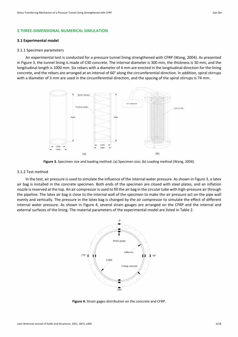
In the test, air pressure is used to simulate the influence of the internal water pressure. As shown in Figure 3, a latex air bag is installed in the concrete specimen. Both ends of the specimen are closed with steel plates, and an inflation nozzle is reserved at the top. An air compressor is used to fill the air bag in the circular tube with high-pressure air through the pipeline. The latex air bag is close to the internal wall of the specimen to make the air pressure act on the pipe wall evenly and vertically. The pressure in the latex bag is changed by the air compressor to simulate the effect of different internal water pressure. As shown in Figure 4, several strain gauges are arranged on the CFRP and the internal and external surfaces of the lining. The material parameters of the experimental model are listed in Table 2.
0°
90°270°
180°
Strain gauge
CFRP
Lining concrete
Adhesive
Figure 4. Strain gages distribution on the concrete and CFRP.
Stress Transferring Mechanism of a Pressure Tunnel Lining Strengthened with CFRP Gan Qin
Latin American Journal of Solids and Structures, 2021, 18(7), e405 6/18
Table 2. Material parameters of the experimental model
Materials Elastic modulus (GPa) Poisson's ratio Density (kg·m-3) Thickness (mm) C30 concrete 30 0.167 2400 30
Longitudinal rebar 210 0.3 7850 - Spiral stirrup 210 0.3 7850 -
CFRP 235 0.28 - 0.1 Adhesive 2 0.35 - 2
3.2 Numerical model
3.2.1 Material models
1. (1) Concrete
A multilinear isotropic hardening behavior is adopted for the concrete. The stress-strain relationship of concrete in tension is calculated using the following equations (GB 50010, 2010):
𝜎𝜎 = (1 − 𝑑𝑑𝑡𝑡)𝐸𝐸𝜀𝜀 (9)
𝑑𝑑𝑡𝑡 = �1 − 𝜌𝜌𝑡𝑡(1.2 − 0.2𝑥𝑥5) 𝑥𝑥 ≤ 11 − 𝜌𝜌𝑡𝑡
𝛼𝛼𝑡𝑡(𝑥𝑥−1)1.7+𝑥𝑥 𝑥𝑥 > 1 (10)
𝑥𝑥 = 𝜀𝜀𝜀𝜀𝑡𝑡,𝑟𝑟
(11)
𝜌𝜌𝑡𝑡 = 𝑓𝑓𝑡𝑡,𝑟𝑟
𝐸𝐸𝜀𝜀𝑡𝑡,𝑟𝑟 (12)
where ε is the tensile strain of concrete under an arbitrary tensile stress; σ is the tensile stress corresponding to any concrete tensile strain; αt is the parameter value of the descending section of the concrete uniaxial tensile stress-strain curve; ft,r is a representative value of concrete uniaxial tensile strength; εt, r is the peak tensile strain of concrete corresponding to a representative value of uniaxial tensile strength; dt is the damage evolution coefficient of concrete under uniaxial tension; and E is the tangent modulus of concrete.
The stress-strain relationship of concrete in compression is calculated using the following equations (GB 50010, 2010):
𝑓𝑓𝑐𝑐 = 𝑓𝑓𝑐𝑐′𝑥𝑥𝜌𝜌𝜌𝜌−1+𝑥𝑥𝜌𝜌
(13)
𝑥𝑥 = 𝜀𝜀𝑐𝑐𝜀𝜀𝑐𝑐′
(14)
𝜌𝜌 = 𝐸𝐸𝐸𝐸−𝐸𝐸𝑠𝑠𝑠𝑠𝑐𝑐
(15)
where fc is the compressive strain at any strain εc; εc' is the strain corresponding to the ultimate compressive strength
(fc') of unconfined concrete; and E and Esec are the tangential and secant modulus, respectively.
2. (2) Rebars and CFRP
A bilinear kinematic hardening model with 1% strain hardening after yielding is adopted for the rebars. The adhesive and CFRP are simplified as linear elastic materials.
3.2.2 3D continuum model
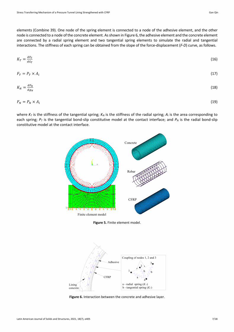
A detailed 3D continuum model of the experimental specimen is established using the 3D finite element analysis software ANSYS to perform the experimental test (Figure 5). Eight-node 3D solid elements (SOLID 65) are used for the concrete. Eight-node 3D solid elements (SOLID 45) are used for the adhesive. Four-node shell elements (SHELL 63) are used for the CFRP. The bond slip behavior of the contact interface between the adhesive and concrete is simulated using spring
Stress Transferring Mechanism of a Pressure Tunnel Lining Strengthened with CFRP Gan Qin
Latin American Journal of Solids and Structures, 2021, 18(7), e405 7/18
elements (Combine 39). One node of the spring element is connected to a node of the adhesive element, and the other node is connected to a node of the concrete element. As shown in Figure 6, the adhesive element and the concrete element are connected by a radial spring element and two tangential spring elements to simulate the radial and tangential interactions. The stiffness of each spring can be obtained from the slope of the force-displacement (F-D) curve, as follows.
𝐾𝐾𝑇𝑇 = 𝑑𝑑𝐹𝐹𝑇𝑇𝑑𝑑𝐺𝐺𝑇𝑇
(16)
𝐹𝐹𝑇𝑇 = 𝑃𝑃𝑇𝑇 × 𝐴𝐴𝑖𝑖 (17)
𝐾𝐾𝑁𝑁 = 𝑑𝑑𝐹𝐹𝑁𝑁𝑑𝑑𝑔𝑔𝑁𝑁
(18)
𝐹𝐹𝑁𝑁 = 𝑃𝑃𝑁𝑁 × 𝐴𝐴𝑖𝑖 (19)
where KT is the stiffness of the tangential spring; KN is the stiffness of the radial spring; Ai is the area corresponding to each spring; PT is the tangential bond-slip constitutive model at the contact interface; and PN is the radial bond-slip constitutive model at the contact interface.
CFRP
Finite element model
Concrete
Rebar
Figure 5. Finite element model.
Coupling of nodes 1, 2 and 3
a - radial spring (KN)b - tangential spring (KT)
CFRP
1
23
4a
b b
Liningconcrete
Adhesive
Figure 6. Interaction between the concrete and adhesive layer.
Stress Transferring Mechanism of a Pressure Tunnel Lining Strengthened with CFRP Gan Qin
Latin American Journal of Solids and Structures, 2021, 18(7), e405 8/18
A bilinear bond slip model has a simple expression, which can better model the basic characteristics of the bond slip relationship between the adhesive layer and the concrete reinforcement interface and is the most commonly used model to simulate the interface behavior between CFRP and concrete (Hugo et al., 2013; Obaidat et al., 2013). Therefore, a bilinear bond slip model is selected as the tangential and radial bond slip constitutive relationship of the concrete reinforcement interface, as shown in Equations 20 and 21:
𝑃𝑃𝑇𝑇 = �
𝑃𝑃𝑇𝑇max𝑔𝑔𝑇𝑇max
𝑔𝑔𝑇𝑇 0 ≤ 𝑔𝑔𝑇𝑇 ≤ 𝑔𝑔𝑇𝑇max𝑃𝑃𝑇𝑇max
𝑔𝑔𝑇𝑇𝑇𝑇−𝑔𝑔𝑇𝑇max(𝑔𝑔𝑇𝑇𝑇𝑇 − 𝑔𝑔𝑇𝑇) 𝑔𝑔𝑇𝑇max ≤ 𝑔𝑔𝑡𝑡 ≤ 𝑔𝑔𝑇𝑇𝑇𝑇
(20)
𝑃𝑃𝑁𝑁 = �
𝑃𝑃𝑁𝑁max𝑔𝑔𝑁𝑁max
𝑔𝑔𝑁𝑁 0 ≤ 𝑔𝑔𝑁𝑁 ≤ 𝑔𝑔𝑁𝑁max𝑃𝑃𝑁𝑁max
𝑔𝑔𝑁𝑁𝑇𝑇−𝑔𝑔𝑁𝑁max(𝑔𝑔𝑁𝑁𝑇𝑇 − 𝑔𝑔𝑁𝑁) 𝑔𝑔𝑁𝑁max ≤ 𝑔𝑔𝑁𝑁 ≤ 𝑔𝑔𝑁𝑁𝑇𝑇
(21)
where PTmax is the tangential peak stress of the interface; gT is the tangential slip; gTmax is the tangential slip corresponding to the tangential peak stress; gTu is the tangential limit slip; PNmax is the radial peak stress of the interface; gN is the radial slip; gNmax is the slip corresponding to the radial peak stress; and gNu is the radial limit slip. The values of the six parameters are obtained using the suggestions of Lorenzis and Zavarise (2009), as shown in Table 3.
Table 3 Interfacial bond slip parameters
PNmax PTmax gNmax gTmax gNu gTu 2 MPa 4 MPa 0.01 mm 0.02 mm 0.1 mm 0.2 mm
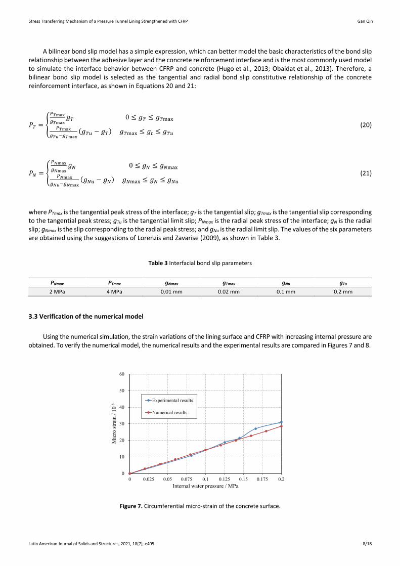
3.3 Verification of the numerical model
Using the numerical simulation, the strain variations of the lining surface and CFRP with increasing internal pressure are obtained. To verify the numerical model, the numerical results and the experimental results are compared in Figures 7 and 8.
0
10
20
30
40
50
60
0 0.025 0.05 0.075 0.1 0.125 0.15 0.175 0.2坐标轴标题
Experimental results
Numerical results
Mic
ro st
rain
/ 10
-6
Internal water pressure / MPa
Figure 7. Circumferential micro-strain of the concrete surface.
Stress Transferring Mechanism of a Pressure Tunnel Lining Strengthened with CFRP Gan Qin
Latin American Journal of Solids and Structures, 2021, 18(7), e405 9/18
0
20
40
60
80
100
0 0.025 0.05 0.075 0.1 0.125 0.15 0.175 0.2坐标轴标题
Experimental results
Numerical results
Mic
ro st
rain
/ 10
-6
Internal water pressure / MPa
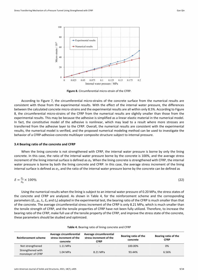
Figure 8. Circumferential micro-strain of the CFRP.
According to Figure 7, the circumferential micro-strains of the concrete surface from the numerical results are consistent with those from the experimental results. With the effect of the internal water pressure, the differences between the calculated concrete micro-strains and the experimental results are all within only 8.5%. According to Figure 8, the circumferential micro-strains of the CFRP from the numerical results are slightly smaller than those from the experimental results. This may be because the adhesive is simplified as a linear elastic material in the numerical model. In fact, the constitutive model of the adhesive is nonlinear, which may lead to a result where more stresses are transferred from the adhesive layer to the CFRP. Overall, the numerical results are consistent with the experimental results, the numerical model is verified, and the proposed numerical modeling method can be used to investigate the behavior of a CFRP-adhesive-concrete multilayer composite structure subject to internal pressure.
3.4 Bearing ratio of the concrete and CFRP
When the lining concrete is not strengthened with CFRP, the internal water pressure is borne by only the lining concrete. In this case, the ratio of the internal water pressure borne by the concrete is 100%, and the average stress increment of the lining internal surface is defined as σ0. When the lining concrete is strengthened with CFRP, the internal water pressure is borne by both the lining concrete and CFRP. In this case, the average stress increment of the lining internal surface is defined as σ1, and the ratio of the internal water pressure borne by the concrete can be defined as
𝛿𝛿 = 𝜎𝜎1𝜎𝜎0
× 100% (22)
Using the numerical results when the lining is subject to an internal water pressure of 0.20 MPa, the stress states of the concrete and CFRP are analyzed. As shown in Table 4, for the reinforcement scheme and the corresponding parameters (Ec, μc, tc, Ea and ta) adopted in the experimental test, the bearing ratio of the CFRP is much smaller than that of the concrete. The average circumferential stress increment of the CFRP is only 8.21 MPa, which is much smaller than the tensile strength of CFRP, and the tensile properties of CFRP have not been fully utilized. Therefore, to increase the bearing ratio of the CFRP, make full use of the tensile property of the CFRP, and improve the stress state of the concrete, these parameters should be studied and optimized.
Table 4. Bearing ratio of lining concrete and CFRP
Reinforcement scheme Average circumferential stress increment of the
concrete
Average circumferential stress increment of the
CFRP
Bearing ratio of the concrete
Bearing ratio of the CFRP
Not strengthened 1.11 MPa - 100.00% 0% Strengthened with monolayer of CFRP 1.04 MPa 8.21 MPa 93.44% 6.56%
Stress Transferring Mechanism of a Pressure Tunnel Lining Strengthened with CFRP Gan Qin
Latin American Journal of Solids and Structures, 2021, 18(7), e405 10/18
4 PARAMETRIC STUDY
A parametric study is performed on the verified numerical model. According to Equation 8, the stress transferred from the CFRP to the concrete can only be influenced by Ec, μc, tc, Ea and ta. According to some practical engineering applications (Dai and Ueda, 2003; Lopez-Gonzalez, et al., 2012; Zhong et al., 2014; Qin, 2015; Wang et al., 2015), the ranges of the five key parameters are listed in Table 5.
Table 5. Parameter values
Parameter Experiment scheme [12] Range [19~23] Ea/Gpa 2 0.01、0.02、0.05、0.1、0.2、0.5、2 ta/mm 2 0.5、1、2、4 Ec/Gpa 235 100、150、200、250、300、600 tc/mm 0.1 0.1、0.15、0.2、0.5、1、2 μc 0.28 0.1、0.2、0.3、0.4
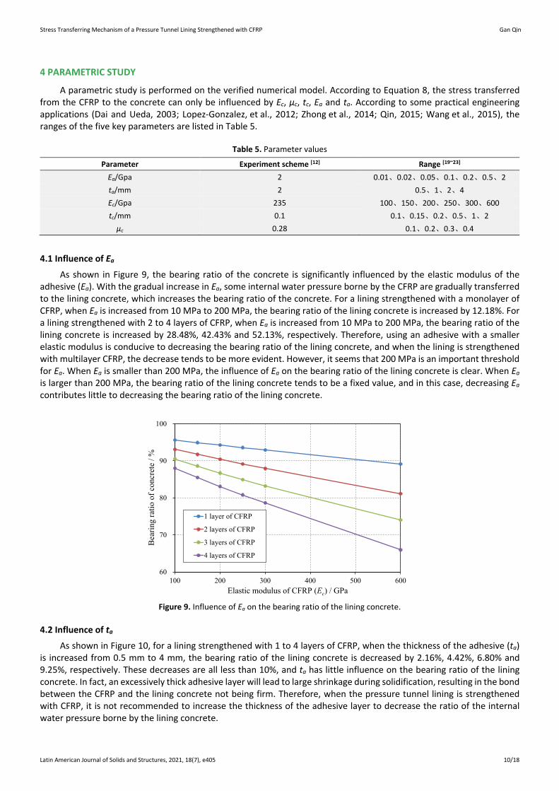
4.1 Influence of Ea
As shown in Figure 9, the bearing ratio of the concrete is significantly influenced by the elastic modulus of the adhesive (Ea). With the gradual increase in Ea, some internal water pressure borne by the CFRP are gradually transferred to the lining concrete, which increases the bearing ratio of the concrete. For a lining strengthened with a monolayer of CFRP, when Ea is increased from 10 MPa to 200 MPa, the bearing ratio of the lining concrete is increased by 12.18%. For a lining strengthened with 2 to 4 layers of CFRP, when Ea is increased from 10 MPa to 200 MPa, the bearing ratio of the lining concrete is increased by 28.48%, 42.43% and 52.13%, respectively. Therefore, using an adhesive with a smaller elastic modulus is conducive to decreasing the bearing ratio of the lining concrete, and when the lining is strengthened with multilayer CFRP, the decrease tends to be more evident. However, it seems that 200 MPa is an important threshold for Ea. When Ea is smaller than 200 MPa, the influence of Ea on the bearing ratio of the lining concrete is clear. When Ea is larger than 200 MPa, the bearing ratio of the lining concrete tends to be a fixed value, and in this case, decreasing Ea contributes little to decreasing the bearing ratio of the lining concrete.
60
70
80
90
100
100 200 300 400 500 600坐标轴标题
1 layer of CFRP
2 layers of CFRP
3 layers of CFRP
4 layers of CFRP
Bea
ring
ratio
ofc
oncr
ete
/ %
Elastic modulus of CFRP (Ec) / GPa Figure 9. Influence of Ea on the bearing ratio of the lining concrete.
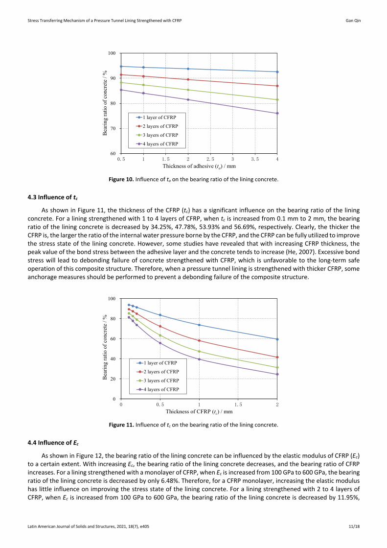
4.2 Influence of ta
As shown in Figure 10, for a lining strengthened with 1 to 4 layers of CFRP, when the thickness of the adhesive (ta) is increased from 0.5 mm to 4 mm, the bearing ratio of the lining concrete is decreased by 2.16%, 4.42%, 6.80% and 9.25%, respectively. These decreases are all less than 10%, and ta has little influence on the bearing ratio of the lining concrete. In fact, an excessively thick adhesive layer will lead to large shrinkage during solidification, resulting in the bond between the CFRP and the lining concrete not being firm. Therefore, when the pressure tunnel lining is strengthened with CFRP, it is not recommended to increase the thickness of the adhesive layer to decrease the ratio of the internal water pressure borne by the lining concrete.
Stress Transferring Mechanism of a Pressure Tunnel Lining Strengthened with CFRP Gan Qin
Latin American Journal of Solids and Structures, 2021, 18(7), e405 11/18
60
70
80
90
100
0.5 1 1.5 2 2.5 3 3.5 4坐标轴标题
1 layer of CFRP
2 layers of CFRP
3 layers of CFRP
4 layers of CFRP
Bear
ing
ratio
of c
oncr
ete
/ %
Thickness of adhesive (ta) / mm Figure 10. Influence of ta on the bearing ratio of the lining concrete.
4.3 Influence of tc
As shown in Figure 11, the thickness of the CFRP (tc) has a significant influence on the bearing ratio of the lining concrete. For a lining strengthened with 1 to 4 layers of CFRP, when tc is increased from 0.1 mm to 2 mm, the bearing ratio of the lining concrete is decreased by 34.25%, 47.78%, 53.93% and 56.69%, respectively. Clearly, the thicker the CFRP is, the larger the ratio of the internal water pressure borne by the CFRP, and the CFRP can be fully utilized to improve the stress state of the lining concrete. However, some studies have revealed that with increasing CFRP thickness, the peak value of the bond stress between the adhesive layer and the concrete tends to increase (He, 2007). Excessive bond stress will lead to debonding failure of concrete strengthened with CFRP, which is unfavorable to the long-term safe operation of this composite structure. Therefore, when a pressure tunnel lining is strengthened with thicker CFRP, some anchorage measures should be performed to prevent a debonding failure of the composite structure.
0
20
40
60
80
100
0 0.5 1 1.5 2坐标轴标题
1 layer of CFRP
2 layers of CFRP
3 layers of CFRP
4 layers of CFRP
Bear
ing
ratio
of c
oncr
ete
/ %
Thickness of CFRP (tc) / mm Figure 11. Influence of tc on the bearing ratio of the lining concrete.
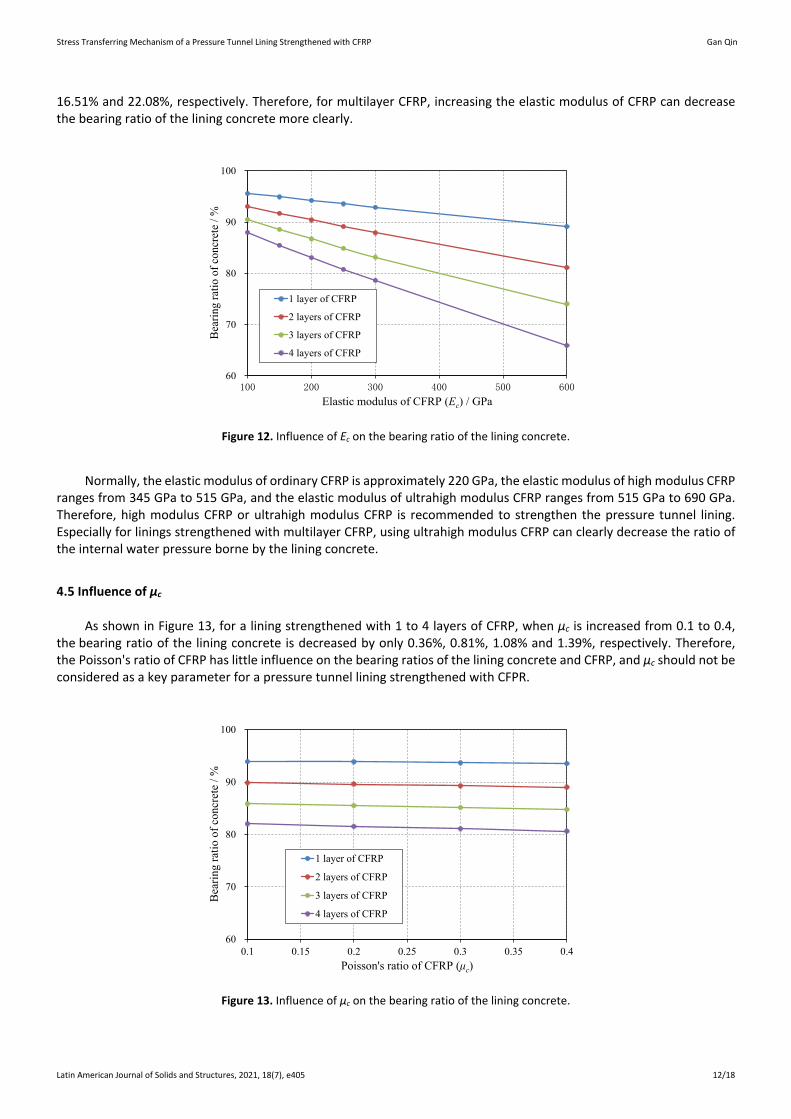
4.4 Influence of Ec
As shown in Figure 12, the bearing ratio of the lining concrete can be influenced by the elastic modulus of CFRP (Ec) to a certain extent. With increasing Ec, the bearing ratio of the lining concrete decreases, and the bearing ratio of CFRP increases. For a lining strengthened with a monolayer of CFRP, when Ec is increased from 100 GPa to 600 GPa, the bearing ratio of the lining concrete is decreased by only 6.48%. Therefore, for a CFRP monolayer, increasing the elastic modulus has little influence on improving the stress state of the lining concrete. For a lining strengthened with 2 to 4 layers of CFRP, when Ec is increased from 100 GPa to 600 GPa, the bearing ratio of the lining concrete is decreased by 11.95%,
Stress Transferring Mechanism of a Pressure Tunnel Lining Strengthened with CFRP Gan Qin
Latin American Journal of Solids and Structures, 2021, 18(7), e405 12/18
16.51% and 22.08%, respectively. Therefore, for multilayer CFRP, increasing the elastic modulus of CFRP can decrease the bearing ratio of the lining concrete more clearly.
60
70
80
90
100
100 200 300 400 500 600坐标轴标题
1 layer of CFRP
2 layers of CFRP
3 layers of CFRP
4 layers of CFRP
Bear
ing
ratio
ofc
oncr
ete
/ %
Elastic modulus of CFRP (Ec) / GPa
Figure 12. Influence of Ec on the bearing ratio of the lining concrete.
Normally, the elastic modulus of ordinary CFRP is approximately 220 GPa, the elastic modulus of high modulus CFRP ranges from 345 GPa to 515 GPa, and the elastic modulus of ultrahigh modulus CFRP ranges from 515 GPa to 690 GPa. Therefore, high modulus CFRP or ultrahigh modulus CFRP is recommended to strengthen the pressure tunnel lining. Especially for linings strengthened with multilayer CFRP, using ultrahigh modulus CFRP can clearly decrease the ratio of the internal water pressure borne by the lining concrete.
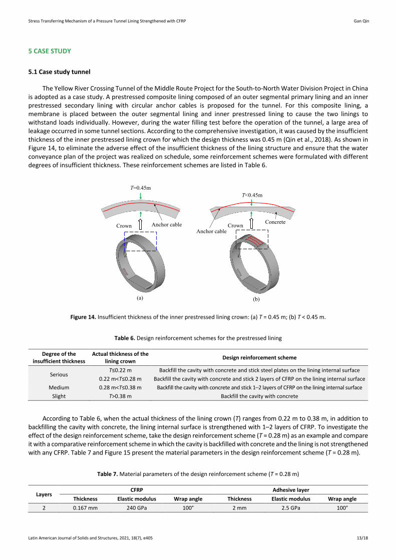
4.5 Influence of μc
As shown in Figure 13, for a lining strengthened with 1 to 4 layers of CFRP, when μc is increased from 0.1 to 0.4, the bearing ratio of the lining concrete is decreased by only 0.36%, 0.81%, 1.08% and 1.39%, respectively. Therefore, the Poisson's ratio of CFRP has little influence on the bearing ratios of the lining concrete and CFRP, and μc should not be considered as a key parameter for a pressure tunnel lining strengthened with CFPR.
60
70
80
90
100
0.1 0.15 0.2 0.25 0.3 0.35 0.4坐标轴标题
1 layer of CFRP
2 layers of CFRP
3 layers of CFRP
4 layers of CFRP
Bea
ring
ratio
ofc
oncr
ete
/ %
Poisson's ratio of CFRP (μc)
Figure 13. Influence of μc on the bearing ratio of the lining concrete.
Stress Transferring Mechanism of a Pressure Tunnel Lining Strengthened with CFRP Gan Qin
Latin American Journal of Solids and Structures, 2021, 18(7), e405 13/18
5 CASE STUDY
5.1 Case study tunnel
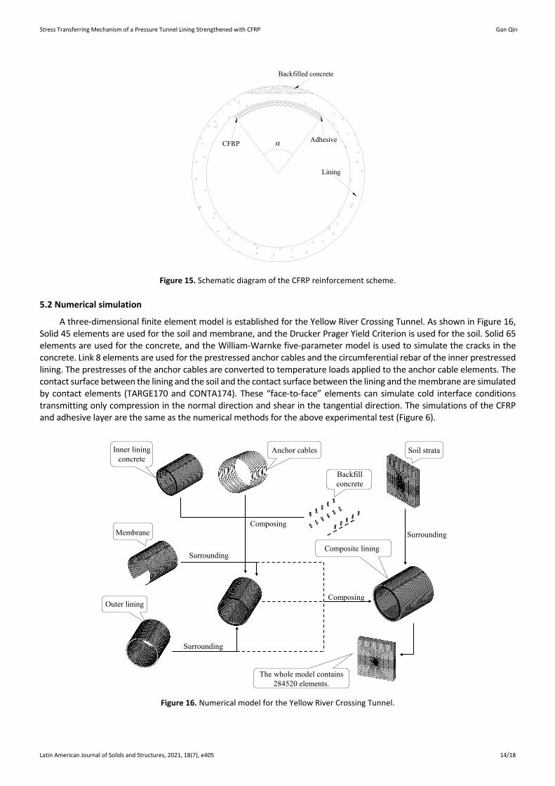
The Yellow River Crossing Tunnel of the Middle Route Project for the South-to-North Water Division Project in China is adopted as a case study. A prestressed composite lining composed of an outer segmental primary lining and an inner prestressed secondary lining with circular anchor cables is proposed for the tunnel. For this composite lining, a membrane is placed between the outer segmental lining and inner prestressed lining to cause the two linings to withstand loads individually. However, during the water filling test before the operation of the tunnel, a large area of leakage occurred in some tunnel sections. According to the comprehensive investigation, it was caused by the insufficient thickness of the inner prestressed lining crown for which the design thickness was 0.45 m (Qin et al., 2018). As shown in Figure 14, to eliminate the adverse effect of the insufficient thickness of the lining structure and ensure that the water conveyance plan of the project was realized on schedule, some reinforcement schemes were formulated with different degrees of insufficient thickness. These reinforcement schemes are listed in Table 6.
Anchor cable
(a) (b)
Crown Crown Concrete
T=0.45mT<0.45m
Anchor cable
Figure 14. Insufficient thickness of the inner prestressed lining crown: (a) T = 0.45 m; (b) T < 0.45 m.
Table 6. Design reinforcement schemes for the prestressed lining
Degree of the insufficient thickness
Actual thickness of the lining crown Design reinforcement scheme
Serious T≤0.22 m Backfill the cavity with concrete and stick steel plates on the lining internal surface
0.22 m<T≤0.28 m Backfill the cavity with concrete and stick 2 layers of CFRP on the lining internal surface Medium 0.28 m<T≤0.38 m Backfill the cavity with concrete and stick 1–2 layers of CFRP on the lining internal surface
Slight T>0.38 m Backfill the cavity with concrete
According to Table 6, when the actual thickness of the lining crown (T) ranges from 0.22 m to 0.38 m, in addition to backfilling the cavity with concrete, the lining internal surface is strengthened with 1–2 layers of CFRP. To investigate the effect of the design reinforcement scheme, take the design reinforcement scheme (T = 0.28 m) as an example and compare it with a comparative reinforcement scheme in which the cavity is backfilled with concrete and the lining is not strengthened with any CFRP. Table 7 and Figure 15 present the material parameters in the design reinforcement scheme (T = 0.28 m).
Table 7. Material parameters of the design reinforcement scheme (T = 0.28 m)
Layers CFRP Adhesive layer
Thickness Elastic modulus Wrap angle Thickness Elastic modulus Wrap angle 2 0.167 mm 240 GPa 100° 2 mm 2.5 GPa 100°
Stress Transferring Mechanism of a Pressure Tunnel Lining Strengthened with CFRP Gan Qin
Latin American Journal of Solids and Structures, 2021, 18(7), e405 14/18
Lining
α AdhesiveCFRP
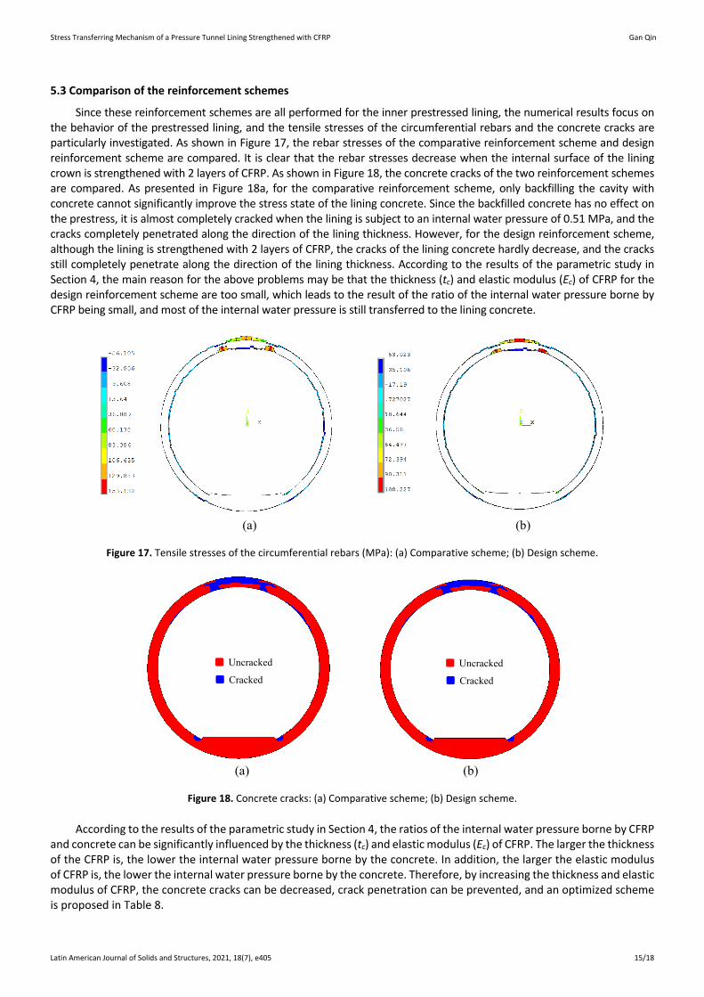
Backfilled concrete
Figure 15. Schematic diagram of the CFRP reinforcement scheme.
5.2 Numerical simulation
A three-dimensional finite element model is established for the Yellow River Crossing Tunnel. As shown in Figure 16, Solid 45 elements are used for the soil and membrane, and the Drucker Prager Yield Criterion is used for the soil. Solid 65 elements are used for the concrete, and the William-Warnke five-parameter model is used to simulate the cracks in the concrete. Link 8 elements are used for the prestressed anchor cables and the circumferential rebar of the inner prestressed lining. The prestresses of the anchor cables are converted to temperature loads applied to the anchor cable elements. The contact surface between the lining and the soil and the contact surface between the lining and the membrane are simulated by contact elements (TARGE170 and CONTA174). These “face-to-face” elements can simulate cold interface conditions transmitting only compression in the normal direction and shear in the tangential direction. The simulations of the CFRP and adhesive layer are the same as the numerical methods for the above experimental test (Figure 6).
Composing
Surrounding
Surrounding
Composing
Anchor cables
Backfill concrete
Membrane
Outer lining
Composite lining
Surrounding
Soil strata
The whole model contains 284520 elements.
Inner liningconcrete
Figure 16. Numerical model for the Yellow River Crossing Tunnel.
Stress Transferring Mechanism of a Pressure Tunnel Lining Strengthened with CFRP Gan Qin
Latin American Journal of Solids and Structures, 2021, 18(7), e405 15/18
5.3 Comparison of the reinforcement schemes
Since these reinforcement schemes are all performed for the inner prestressed lining, the numerical results focus on the behavior of the prestressed lining, and the tensile stresses of the circumferential rebars and the concrete cracks are particularly investigated. As shown in Figure 17, the rebar stresses of the comparative reinforcement scheme and design reinforcement scheme are compared. It is clear that the rebar stresses decrease when the internal surface of the lining crown is strengthened with 2 layers of CFRP. As shown in Figure 18, the concrete cracks of the two reinforcement schemes are compared. As presented in Figure 18a, for the comparative reinforcement scheme, only backfilling the cavity with concrete cannot significantly improve the stress state of the lining concrete. Since the backfilled concrete has no effect on the prestress, it is almost completely cracked when the lining is subject to an internal water pressure of 0.51 MPa, and the cracks completely penetrated along the direction of the lining thickness. However, for the design reinforcement scheme, although the lining is strengthened with 2 layers of CFRP, the cracks of the lining concrete hardly decrease, and the cracks still completely penetrate along the direction of the lining thickness. According to the results of the parametric study in Section 4, the main reason for the above problems may be that the thickness (tc) and elastic modulus (Ec) of CFRP for the design reinforcement scheme are too small, which leads to the result of the ratio of the internal water pressure borne by CFRP being small, and most of the internal water pressure is still transferred to the lining concrete.
(a) (b)
Figure 17. Tensile stresses of the circumferential rebars (MPa): (a) Comparative scheme; (b) Design scheme.
Uncracked
CrackedUncracked
Cracked
(a) (b)
Figure 18. Concrete cracks: (a) Comparative scheme; (b) Design scheme.
According to the results of the parametric study in Section 4, the ratios of the internal water pressure borne by CFRP and concrete can be significantly influenced by the thickness (tc) and elastic modulus (Ec) of CFRP. The larger the thickness of the CFRP is, the lower the internal water pressure borne by the concrete. In addition, the larger the elastic modulus of CFRP is, the lower the internal water pressure borne by the concrete. Therefore, by increasing the thickness and elastic modulus of CFRP, the concrete cracks can be decreased, crack penetration can be prevented, and an optimized scheme is proposed in Table 8.
Stress Transferring Mechanism of a Pressure Tunnel Lining Strengthened with CFRP Gan Qin
Latin American Journal of Solids and Structures, 2021, 18(7), e405 16/18
Table 8. Material parameters of the optimized reinforcement scheme
Scheme CFRP adhesive
Thickness Elastic modulus Wrap angle Thickness Elastic modulus Wrap angle Design scheme 0.167 mm 240 GPa 100° 2 mm 2.5 GPa 100°
Optimized scheme 1 mm 690 GPa 100° 2 mm 2.5 GPa 100°
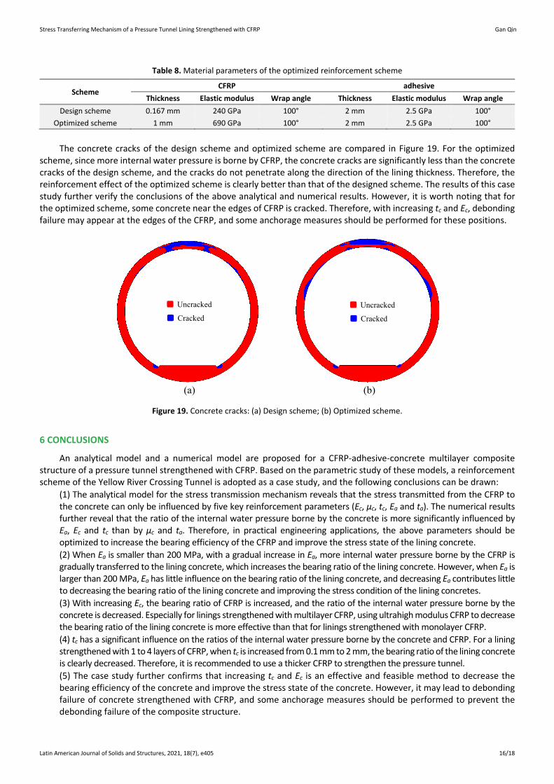
The concrete cracks of the design scheme and optimized scheme are compared in Figure 19. For the optimized
scheme, since more internal water pressure is borne by CFRP, the concrete cracks are significantly less than the concrete cracks of the design scheme, and the cracks do not penetrate along the direction of the lining thickness. Therefore, the reinforcement effect of the optimized scheme is clearly better than that of the designed scheme. The results of this case study further verify the conclusions of the above analytical and numerical results. However, it is worth noting that for the optimized scheme, some concrete near the edges of CFRP is cracked. Therefore, with increasing tc and Ec, debonding failure may appear at the edges of the CFRP, and some anchorage measures should be performed for these positions.
Uncracked
CrackedUncracked
Cracked
(a) (b)
Figure 19. Concrete cracks: (a) Design scheme; (b) Optimized scheme.
6 CONCLUSIONS
An analytical model and a numerical model are proposed for a CFRP-adhesive-concrete multilayer composite structure of a pressure tunnel strengthened with CFRP. Based on the parametric study of these models, a reinforcement scheme of the Yellow River Crossing Tunnel is adopted as a case study, and the following conclusions can be drawn:
(1) The analytical model for the stress transmission mechanism reveals that the stress transmitted from the CFRP to the concrete can only be influenced by five key reinforcement parameters (Ec, μc, tc, Ea and ta). The numerical results further reveal that the ratio of the internal water pressure borne by the concrete is more significantly influenced by Ea, Ec and tc than by μc and ta. Therefore, in practical engineering applications, the above parameters should be optimized to increase the bearing efficiency of the CFRP and improve the stress state of the lining concrete. (2) When Ea is smaller than 200 MPa, with a gradual increase in Ea, more internal water pressure borne by the CFRP is gradually transferred to the lining concrete, which increases the bearing ratio of the lining concrete. However, when Ea is larger than 200 MPa, Ea has little influence on the bearing ratio of the lining concrete, and decreasing Ea contributes little to decreasing the bearing ratio of the lining concrete and improving the stress condition of the lining concretes. (3) With increasing Ec, the bearing ratio of CFRP is increased, and the ratio of the internal water pressure borne by the concrete is decreased. Especially for linings strengthened with multilayer CFRP, using ultrahigh modulus CFRP to decrease the bearing ratio of the lining concrete is more effective than that for linings strengthened with monolayer CFRP. (4) tc has a significant influence on the ratios of the internal water pressure borne by the concrete and CFRP. For a lining strengthened with 1 to 4 layers of CFRP, when tc is increased from 0.1 mm to 2 mm, the bearing ratio of the lining concrete is clearly decreased. Therefore, it is recommended to use a thicker CFRP to strengthen the pressure tunnel. (5) The case study further confirms that increasing tc and Ec is an effective and feasible method to decrease the bearing efficiency of the concrete and improve the stress state of the concrete. However, it may lead to debonding failure of concrete strengthened with CFRP, and some anchorage measures should be performed to prevent the debonding failure of the composite structure.
Stress Transferring Mechanism of a Pressure Tunnel Lining Strengthened with CFRP Gan Qin
Latin American Journal of Solids and Structures, 2021, 18(7), e405 17/18
Acknowledgments
This work is supported by the National Key Research and Development Program of China (No. 2019YFC0810702) supported and the Fundamental Research Funds for the Central Universities (No. JZ2020HGQA0141).
Author’s Contributions: Conceptualization, G Qin and F Yang; Methodology, G Qin; Investigation, G Qin and F Yang; Writing - original draft, G Qin and F Yang; Writing - review & editing, G Qin, F Yang and DQ Jin; Resources, G Qin, F Yang and DQ Jin; Supervision, DQ Jin.
Editor: Marcílio Alves.
References
Chen, H., Wei, X., Jiang, M., Peng, W. and Jin, F. (2015). Blast-loaded behaviors of severely damaged buried arch repaired by anchored CFRP strips. Composite Structures, 122, 92-103.
Dai, J. G. and Ueda, T. (2003). Local bond stress slip relations for FRP sheets-concrete interfaces. Fibre-reinforced polymer reinforcement for concrete structures - the sixth international symposium on FRP reinforcement for concrete structures, Singapore (pp. 143-152).
Farhadian, H., Nikvar Hassani, A. and Katibeh, H. (2017). Groundwater inflow assessment to Karaj Water Conveyance tunnel, northern Iran. KSCE Journal of Civil Engineering, 21, 2429-2438.
GB 50010 (2010). Code for design of concrete structures. Beijing, China, China Architecture and Building Press.
He, C., Tang, Z.C., Wang, B., Wang, Y. and She, J. (2009). Research on effect of inner surface reinforcing on structure bearing capacity by model test in defective tunnel. Rock and Soil Mechanics, 30(2), 406-412.
He, X.J. (2007). Studies on flexural behavior and debonding mechanism of RC beams FRP-strengthened at different preloaded states. PhD thesis, Changsha: Central South University.
Hugo, C.B., Carlos, C. and Manuel, A.G.S. (2013). linear and nonlinear analysis of bond slip models for interfaces between FRP composites and concrete. Composites: Part B, 45, 1554-1568.
Lai, J., He, S., Qiu, J., Chen, J., Wang, L., Wang, K. and Wang, J. (2017). Characteristics of seismic disasters and aseismic measures of tunnels in Wenchuan earthquake. Environmental Earth Sciences, 76(2), 94.
Li, Y.J. and Liu, Z.Q. (2007). Application of CFRP reinforcement technology in hydraulic tunnel. Yellow River, 29(4), 66-68.
Liu, D.J., Huang, H.W., Xue, Y.D. and Wang, M.Z. (2014). Research on behavior of tunnel lining strengthened by textile-reinforced concrete. Engineering Mechanics, 31(7), 91-90.
Liu, X., Sang, Y., Ding, S., You, G. and Jiang, L. (2020). Experimental study on the mechanics characteristics of CFRP strengthening of highway tunnels at different damage states. Geofluids, 2020(7), 1-11.
Lopez-Gonzalez, J.C., Fernandez-Gomez, J. and Gonzalez-Valle, E. (2012). Effect of adhesive thickness and concrete strength on FRP-concrete bonds. Journal of Composites for Construction, 16(6), 705-711.
Lorenzis, L.D. and Zavarise, G. (2009). Interfacial stress analysis and prediction of debonding for a thin plate bonded to a curved substrate. International Journal of Non-Linear Mechanics, 44(4), 358-370.
Obaidat, Y. T., Heyden, S. and Da Hlblom, O. (2013). Evaluation of parameters of bond action between frp and concrete. Journal of Composites for Construction, 17(5), 626-635.
Qin, G., Cao, S.R. and Yang, F. (2018). Effect of deficiencies in the tunnel crown thickness on pressure tunnels with posttensioned concrete linings. Advances in Civil Engineering, 2018, 1-14.
Qin, P. (2015). Research of seismic performance on CFRP confined concrete-filled steel tubular columns. PhD thesis, Changsha: Hunan University.
Sun, Z.Y., Wu, G., Zhang, J., Zeng, Y.H. and Xiao, W.C. (2017). Experimental study on concrete columns reinforced by hybrid steel-fiber reinforced polymer (FRP) bars under horizontal cyclic loading. Construction and Building Materials, 130, 202-211.
Stress Transferring Mechanism of a Pressure Tunnel Lining Strengthened with CFRP Gan Qin
Latin American Journal of Solids and Structures, 2021, 18(7), e405 18/18
Li, T., Chen, L., Shangguan, J. and Peng, Q. (2011). Application of carbon fiber sheet (CFS) on diversion tunnel reinforcement of Qingshan Reservoir. Yangtze River, 42(12), 53-55.
Wang L.Y. (2004). The experimental study on pressure conduit of ferroconcrete reinforced by fabric reinforced plastic. Master thesis, Wuhan: Wuhan University.
Wang, L.B., Wu, Y. and Mohammad, N. (2015). Parameters of static response of carbon fiber reinforced polymer (CFRP) suspension cables. Journal of Central South University, 22(08), 3123-3132.
Wang, P., Jiang, M., Zhou, J., Wang, B., Feng, J., Chen, H., et al. (2018). Spalling in concrete arches subjected to shock wave and CFRP strengthening effect. Tunnelling and Underground Space Technology, 74, 10-19.
Wang, T.T. and Lee C.H. (2012). Life-Cycle design considerations for hydraulic tunnels: lessons learned from inspection and maintenance cases. Journal of Performance of Constructed Facilities, 27(6), 796-806.
Wang, W. L., Wang, T. T., Su, J. J., Lin, C. H., Seng, C. R. and Huang, T. H. (2001). Assessment of damage in mountain tunnels due to the Taiwan Chi-Chi earthquake. Tunnelling and underground space technology, 16(3), 133-150.
Xie, W., Jiang, M., Chen, H., Zhou, J. and Jin, F. (2014). Experimental behaviors of cfrp cloth strengthened buried arch structure subjected to subsurface localized explosion. Composite Structures, 116(1), 562-570.
Yang, G., Wang, G., Lu, W., Yan, P. and Chen, M. (2019). Damage assessment and mitigation measures of underwater tunnel subjected to blast loads. Tunnelling and Underground Space Technology, 94, 103131.
Yang, Q.G. and Gao, D.S. (2011). Prospect and status of reinforcement technology of dangerous reservoir in China. Yangtze River, 42(12), 6-11.
Yuan, H. and Li, F. (2010). Peeling behavior and spalling resistance of CFRP sheets bonded to bent concrete surfaces. Acta Mechanica Sinica, 26, 257-264.
Zhang W.S., Cheng, S.J. and Liu, Y.M. (2005). The experimental study on pressure conduits of fiber reinforced concrete. China Rural Water and Hydropower, (6), 54-57.
Zhang, L. and Teng, J.G. (2010a). Finite element prediction of interfacial stresses in structural members bonded with a thin plate. Engineering structures, 32(2), 459-471.
Zhang, L. and Teng, J.G. (2010b). Simple general solution for interfacial stresses in plated beams. Journal of Composites for Construction, 14(4), 434-442.
Zhong, Z.Q., Yu, Y. and Liu, B. (2014). Experimental study on influence of adhesive layer thickness on bond stress of concrete beams strengthened with prestresses CFRP. China Journal of Highway and Transport, 27(11), 55-62.