Embed Size (px)
Citation preview
Research ArticleThe Stability Analysis of Tunnel Lining Structure with SeismicExcitation Based on the Energy Evaluation Principle
Yumin Wen12 Chunlei Xin 34 Xi Zhang12 Zeming Huang34 Yusheng Shen 12
Wenjie Lei5 and Bo Gao2
1Key Laboratory of Transportation Tunnel Engineering of the Ministry of Education Southwest Jiaotong UniversityChengdu 610031 China2National Engineering Laboratory for Technology of Geological Disaster Prevention in Land TransportationSouthwest Jiaotong University Chengdu 610031 China3State Key Laboratory of Geohazard Prevention and Geoenvironment Protection Chengdu University of TechnologyChengdu 610059 China4College of Environment and Civil Engineering Chengdu University of Technology Chengdu 610059 China5College of Water Conservancy and Hydropower Engineering Sichuan Agricultural University Yarsquoan 625000 China
Correspondence should be addressed to Chunlei Xin xinchunleicduteducn
Received 14 March 2021 Accepted 9 July 2021 Published 20 July 2021
Academic Editor FuRen Ming
Copyright copy 2021 Yumin Wen et al )is is an open access article distributed under the Creative Commons Attribution Licensewhich permits unrestricted use distribution and reproduction in any medium provided the original work is properly cited
Earthquakes are vibrations induced by the rapid releases of large quantities of energy from the crustal movements During seismicexcitation there are kinetic energy damping energy and strain energy acting on the tunnel structure Based on the indexes of thetotal energy releasable elastic strain energy and dissipated energy this paper proposes three energy evaluation criteria for thetunnel structure which are applied to the optimization of the aseismic design of the cross-sectional shape andmaterial property ofthe tunnel structure It can be concluded that the peak values and accumulated values of elastic strain energy at the spandrel andarch springing are significantly larger than other positions which indicates that the strengths of the spandrel and arch springingare the most influential factor for the seismic damage of the tunnel structure Considering this factor the width-to-height ratio of133 and Poissonrsquos ratio of 03 are determined as the most optimal cross-sectional shape and material property respectivelyFurthermore by analyzing the relationship between the internal energy and the input energy of the tunnel structure with seismicexcitation and proposing an equation for the evaluation of the dynamic stability of tunnel structure the stabilities of the tunnelstructure with different PGAs are analyzed it can be concluded that the larger the peak value of seismic wave acceleration thelonger the instable period and the greater the degree of dynamic instability)e derived equations can be used as references for theseismic analysis of the tunnel structure and the conclusions of this paper can contribute to the aseismic design of tunnel lining
1 Introduction
Energy is an index that describes the state of the wholesystem [1] which includes the overall dynamic response[2 3] structural parameters [4] and external excitation [5])erefore the mechanism of the instability of structureswith seismic excitation can be revealed based on the prin-ciple of energy [6]
Originally the convergence or divergence of the motionindex based on the periodic load was proposed to analyze the
dynamic response of structures [7] However there would bea jump phenomenon when applied to the nonlinear dynamicresponse analysis [8] Afterwards the quasi-static stiffnessprinciple based on the tangent stiffness matrix was proposed[9 10] which could evaluate the dynamic instability con-ditions of structures [11] In terms of that principle themotion equation was transformed to the differential equa-tion of the first order [12] and its stability can be evaluatedby the positive definite stability theory of the matrix inmotion [13] Moreover in regard to the B-R principle
HindawiShock and VibrationVolume 2021 Article ID 9995682 17 pageshttpsdoiorg10115520219995682
incremental dynamic analysis (IDA) curves were used todescribe the relation of the strength and displacement [14]which could be effectively used for the dynamic stabilityanalysis of structures However the IDA curves occasionallydisplayed nonmonotonic behaviors and discontinuouspoints [15] sometimes it was difficult to use them to identifythe critical strength of structures [16 17] which could in-fluence the dynamic stability analysis of structures [18]hence there was no unified quantitative criterion to definethe dynamic response of structures based on the B-Rprinciple [19]
Recently the principle of energy conservation was usedto describe the dynamic instability mechanism of structureswith seismic excitation [20 21] pointing out that thestructures were stable when the input seismic energy was lessthan the critical value of the energy possessed by thestructures [22] However it was difficult to determine thecritical value of the energy possessed by complex structureswith seismic excitation [23 24]
)e stability of the tunnel structure with seismic excitationis closely related to the external vibration intensity and internalstructural characteristics [25] it is essential to adopt an ap-propriate principle to evaluate the stability of the tunnelstructure with seismic excitation [26 27] From the perspectiveof the energy generated from the system and the internal tunnelstructure induced by seismic excitation and considering theexternal vibration intensity and structural characteristics [28]the physical mechanism of seismic instability of complex de-formation in the tunnel structure is researched in this paper
2 The Methodology
21 Energy Balance Equation of Tunnel Structure Onlyconsidering the single layer structure of tunnel lining themulti-degree-of-freedom equation of motion can beexpressed as follows [29]
M eurou (t) + C _u(t) + f(u t) minusMr _ug(t) (1)
whereM is the mass matrix C is the damping matrix f(u t)
is the internal force r is the load impact matrix _ug(t) is theseismic ground acceleration vector and eurou(t) _u(t) and u(t)
are the acceleration velocity and displacement vectorsrespectively
Considering that the aseismic stability of the structure isclosely related to the internal structural characteristics andexternal excitation load integrating the terms in equation (1)over time the energy equation in the form of work can beobtained as follows [30]
1113946t
0_uTMeurou (t)dt + 1113946
t
0_uTC _u(t)dt + 1113946
t
0_uTf(u t)dt minus 1113946
t
0Mr _ug(t)dt
(2)
Rewriting equation (2) into the energy balance equationequation (3) can be obtained as follows [31]
EK(t) + ED(t) + ES(t) EI(t) (3)
where EK(t) is the kinetic energy ED(t) is the dampingenergy ES(t) is the strain energy and EI(t) is the input total
energy Each term can be expressed as the followingequations respectively
EK(t) 1113946t
0_uTMeurou (t)dt (4)
ED(t) 1113946t
0_uT
C _u(t)dt (5)
ES(t) 1113946t
0_uTf(u t)dt (6)
EI(t) minus 1113946t
0Mr _ug(t)dt (7)
226ree Energy Evaluation Criteria of the Stability of TunnelStructure
221 Stability Evaluation Criterion Based on the TotalEnergy When the structure is motivated by the externalexcitation [32] there are kinetic energy damping energyand strain energy existing inside the structure [33 34] )estructure is dynamically stable when the total input energy isequal to the sum of the internal strain energy and dissipatedenergy [35])e structure is still dynamically stable when thetotal input energy is greater than the sum of the internalstrain energy and dissipated energy due to the fact that theredundant input energy will transform to other forms ofenergy to be dissipated [36 37] On the contrary when thetotal input energy is less than the sum of the internal strainenergy and dissipated energy the structure is no longerstable and extradeformation will occur to offset the energydifference inside and outside the system )erefore thephysical mechanism of structural dynamic instability can beattributed to the unbalance of the energy required bystructural deformation and external input energy [38] )estate of the dynamic balance can be expressed as
Fext(t) Fint(t) (8)
where Fext(t) is the instantaneous external force vector andFint(t) is the instantaneous internal force vector Regardingthe structural dynamic force damping force and the seismicforce as the external force vector and regarding the restoringforce generated by structural deformation as the internalforce vector the following equations can be obtained as
Fext(t) minusMr _ug(t) minus Meurou (t) minus C _u(t) (9)
Fint(t) f(u t) (10)
)e instantaneous work done by the instantaneous ex-ternal force vector with seismic excitation can be expressedas
Wext(t) minusMr _ug(t) minus Meurou(t) minus C _u(t)1113960 1113961Tu(t) (11)
)e work done by the restoring force vector of the in-ternal deformation of the structure at a certain time can beexpressed as
2 Shock and Vibration
Wint(t) 1113946u
0f(u t)du (12)
)e difference between the instantaneous work done bythe external and internal force vectors is denoted as W(t)and equation (13) can be obtained as
W(t) minusMr _ug(t) minus M eurou(t) minus C _u(t)1113960 1113961Tu(t) minus 1113946
u
0f(u t)du
(13)
From the perspective of thermodynamics the work doneby the internal and external forces during an adiabaticprocess actually represents the variation of the energy ratherthan the stored energy in the structure [39] With seismicexcitation the work done by the internal and external forcesof the structure is constantly varying which can be expressedas
Eintr(t) |W(t)| Wext(t) minus Wint(t)1113868111386811138681113868
1113868111386811138681113868 (14)
)erein the input energy of the structure can be cal-culated by equation (7) )e structure is instable when theinput energy EI(t) is less than the internal energy Eintr(t) itwill absorb extra energy to offset the input energy so that theinput energy can be equal to or greater than the intrinsicenergy which represents the dynamic stable state)ereforebased on the energy evaluation principle the structuralstability can be expressed as
Eintr(t)leEI(t) stable tgt 0
Eintr(t)gtEI(t) instable tlt 0(15)
)erefore if the intrinsic energy curve of the structureexceeds the input energy curve the structure is in a dynamicinstable state the dynamic stability equation can beexpressed as
S(t) EI(t) minus Eintr(t) (16)
where the structure is dynamically stable when S(t)ge 0 andthe structure is instable when S(t)lt 0
222 Strength Failure Criterion Based on the DissipatedEnergy According to the law of thermodynamics energyconversion is an essential feature of the physical process andsubstance destruction is a phenomenon of instability in-duced by energy [40 41] According to equation (3) theaccumulated elastic strain energy ES(t) can be divided intothe elastic strain energy Ee(t) and the plastic strain energyEp(t) as shown in
ES(t) Ee(t) + Ep(t) (17)
In the process of element deformation the elastic strainenergy at the elastic stage continues to increase until theyield limit is reached which means that the elastic strainenergy of the element reaches the maximum [42] When theyield limit is exceeded the material will undergo an irre-coverable plastic deformation and it reaches the maximumwhen the material is almost destroyed which means that the
accumulated plastic strain energy reached the maximum[43 44] With seismic excitation the structure elementsalternatively exhibit tension and compression they willexperience the cycle of loading compaction elasticityplasticity and unloading which induces cyclic impact on thematerial and brings about crack expansion crack penetra-tion and even damage of the structure [45]
During seismic excitation seismic energy is continuouslyinput into the structural system over time a part of seismicenergy is dissipated by the structure through its damping andplastic deformation and the other part of seismic energy isconverted into the kinetic energy of the structure or absorbed inthe form of elastic strain energy of the structure [46] It can beconcluded from equation (3) that the total input energy of thestructure is converted to the kinetic energy damping energyelastic strain energy and plastic strain energy In view of that theelastic strain energy and plastic strain energy correspond to thedeformation states of the structure the stability of the structurecan be evaluated by calculating the strain energy and analyzingthe tendency of the strain energy [47 48]
(1) Strain Energy )e strain energy density can becalculated from the stress and strain of the structure ele-ments as shown in
w 1113946 σijεijdεij (18)
)ere is a strain equation for the elastoplastic material asshown in
εij εeij + εp
ij (19)
)e strain energy density is expressed as
w 12σijε
eij + σijε
pij (20)
Besides the strain energy of the element can beexpressed as
we 1113946V
wdv (21)
where w is the strain energy density of the element and we isthe strain energy of the element
)e total strain energy of the structure can be obtainedby summing the strain energy of each element as shown in
W 1113944 we (22)
(2) Strength Failure 6eory Based on the DissipatedEnergy Considering the deformation of the element withexternal force assuming that there is no heat exchange withsurrounding and denoting the total input energy generatedby the external force as U the following equation can beobtained according to the first law of thermodynamics as
U Up
+ Ue (23)
where Up is the plastic strain energy and Ue is the releasableelastic strain energy )e plastic strain energy Up is used toform internal damage and plastic deformation which resultin the strength failure and the release of the elastic strain
Shock and Vibration 3
energy Ue stored in the element is the underlying reason forthe sudden failure of the tunnel element
)e energy of each part of the element in the principalstress space can be expressed as follows
U 1113946ε1
0σ1dε1 + 1113946
ε2
0σ2dε2 + 1113946
ε3
0σ3dε3 (24)
Ue
12σ1ε
e1 +
12σ2ε
e2 +
12σ3ε
e3 (25)
Up
U minus Ue (26)
)e energy damage quantity of the tunnel element can bedefined as
ϖ U
p
Uc (27)
where Uc is the critical value of energy dissipation when theelement loses its strength which is a material constantdetermined by the uniaxial tension test uniaxial compres-sion test and pure shear test the calculation method of Uc issame as that of Up When ϖ 1 it denotes that the material
loses its strength no matter what stress state the material isin which can be expressed as
ϖ U
p
Uc 1 (28)
Substituting equation (28) into equations (25) and (26)the strength failure criterion based on the dissipated energycan be obtained as
1113946ε1
0σ1dε1 + 1113946
ε2
0σ2dε2 + 1113946
ε3
0σ3dε3 minus
12σ1ε
e1 minus
12σ2ε
e2 minus
12σ3ε
e3 U
c
(29)
223 Overall Failure Criterion Based on the ReleasableElastic Strain Energy It can be concluded from equation(25) that the releasable strain energy stored by the element isrelated to the unloading elastic modulus Ei and Poissonrsquosratio v after damaged Considering the orthotropy of theelement damage the damage is directly related to theelasticity Assuming that the compressive stress is positivewhen the element is not damaged it can be expressed as
Ue
12σiε
ei
12
σ21E1
+σ22E2
+σ23E3
minus v1
E1+
1E2
1113888 1113889σ1σ2 +1
E1+
1E3
1113888 1113889σ1σ3 +1
E2+
1E3
1113888 1113889σ2σ31113890 11138911113896 1113897 (30)
In terms of the damaged structure the conventionaldamage variable ωi is introduced to consider the effect ofdamage on the unloading modulus Ei of the structure asshown in
Ei 1 minus ωi( 1113857E0 (31)
where E0 is the initial elastic modulus when the structure isnot damaged
Assuming that Poissonrsquos ratio is not affected by thedamage and substituting it into equation (30) then thefollowing equation can be obtained as
Ue
12σiε
ei
12E0
σ211 minus ω1
+σ22
1 minus ω2+
σ231 minus ω3
minus v1
1 minus ω1+
11 minus ω2
1113888 1113889σ1σ2 +1
1 minus ω1+
11 minus ω3
1113888 1113889σ1σ3 +1
1 minus ω2+
11 minus ω3
1113888 1113889σ2σ31113890 11138911113896 1113897 (32)
Considering the average effect of the damage along thethree directions of the principal stresses equation (32) canbe simplified as
E E0(1 minus ω)
v v
1 minus ω
ωi ω i 1 2 and 3
(33)
)e releasable elastic strain energy can be rewritten as
Ue
12E
σ21 + σ22 + σ23 minus 2v σ1σ2 + σ1σ3 + σ2σ31113858 11138591113966 1113967 (34)
Herein the average values E v andω can be determinedby the unidirectional cyclic compression loading andunloading tests It can also be taken as the initial elastic
modulus E0 and Poissonrsquos ratio v for convenience thenequation (34) can be rewritten as
Ue
12E
σ21 + σ22 + σ23 minus 2v σ1σ2 + σ1σ3 + σ2σ31113858 11138591113966 1113967 (35)
Equation (35) is aimed at the linear unloading process inthe nonlinear process of the element Summing up the re-leasable elastic strain energy Ue
i of each element the re-leasable elastic strain energy 1113936 Ue
i of the whole structure canbe obtained As the damage of the element increases withexternal action the strength gradually decreases when thereleasable elastic strain energy Ue
i of an element reaches thesurface energy U0 required by the element damage Ue
i willbe released in the form of elastic surface energy When thedamaged elements reach a certain critical number the wholestructure will be damaged
4 Shock and Vibration
Based on the above releasable energy concept the overallfailure criterion of the structure element can be concludedthat a part of the work done by the external force on thestructure is converted into the dissipated energy Up whichmakes the structure gradually loses its strength and theother part is converted into the gradually increasing re-leasable elastic strain energy Ue When Ue reaches the valueof the surface energy U0 of the tunnel element the strainenergy Ue is released and the whole structure element isdamaged In the principal stress space Ue is difficult to bereleased along the direction of the maximum compressivestress σ1 but is apt to be released along the direction of theminimum compressive stress or tensile stress σ3 )e overallfailure criteria of the element with compressive stress andtensile stress are given below
(1) 6ree-Directional Compressive Stress State(σ1 gt σ2 gt σ3 ge 0 Assuming 6at the Compressive Stress IsPositive) When the element is in a three-directional com-pressive stress state and the overall instability occurs thereleasable elastic strain energy will be released along thethree directions of stresses )e quantity of the releasedenergy is proportional to the releasable energy stored in theelement and the released strain energy Gi along each di-rection is distributed according to the difference value withthe maximum principal stress which can be expressed as
Gi Ki σ1 minus σi( 1113857Ue (36)
where G3 is the positive correlation coefficient that can bedetermined by the uniaxial compression test and Gc is thereleasable elastic strain energy in the element
It can be known from equation (36) that the releasableelastic strain energy in the element is primarily releasedalong the third principal stress direction When the releasedstrain energy along the third principal stress direction G3reaches a critical value Gc the releasable elastic strain energywill be released firstly along this direction which can beexpressed as
G3 K3 σ1 minus σ3( 1113857Ue
Gc (37)
where Gc is the material constant of the element which canbe determined by the uniaxial compression test When thetunnel element is in the uniaxial compression state theelement will be overall instable if the element undergoesstrength failure Assuming that σ1 σc when the elementundergoes uniaxial compression strength failure then σ2
σ3 0 and the following equation can be obtained as
Ue
σ2c2E0
(38)
Substituting equation (38) into equation (37) the fol-lowing equation can be obtained as
Gc K3σ3c2E0
(39)
)erefore the instability criterion of the element in thethree-directional compressive stress state can be obtained as
Ue
σ2c
2E0 σ1 minus σ3( 1113857 (40)
It can be also expressed as
σ1 minus σ3( 1113857 σ21 + σ22 + σ23 minus 2v σ1σ2 + σ1σ3 + σ2σ3( 11138571113960 1113961 σ3c
(41)
(2) Stress State with Both Tension and Compression(σ1 gt 0 σ3 lt 0) When at least one of the principal stresses istensile stress considering that the tensile stress of anymagnitude will promote the energy release of the damagedelement the stored releasable strain energy Ue is distributedaccording to the principal stress value along the three di-rections of principal stress )erefore the energy release rateGi of the element along the σi direction can be defined as
Gi KiσiUe (42)
)e releasable elastic strain energy in the element isprimarily released along the direction of the maximumprincipal tensile stress)erefore it is necessary to satisfy thefollowing equation when the overall instability occurs
G3 K3σ3Ue
Gt (43)
where Gt is the critical strain energy release rate of the el-ement with tensile stress which is a material constant de-termined by the uniaxial tensile test
When the element is in uniaxial tension state it will bedamaged if the strength is lost Assuming that σ3 σt σ1
σ2 0 and substituting them into equation (35) the fol-lowing equation can be obtained as
Ue
σ2t2E0
(44)
)en substituting it into equation (42) the followingequation can be obtained as
Gt K3σ3t2E0
(45)
Moreover substituting equation (45) into equation (43)the following equation can be obtained as
σ3Ue
σ3t2E0
(46)
Eventually substituting equation (46) into equation (35)the overall instability criterion in the stress state with bothtension and compression can be obtained as
σ3 σ21 + σ22 + σ23 minus 2v σ1σ2 + σ1σ3 + σ2σ3( 11138571113960 1113961 σ3t (47)
3 Numerical Simulation
)e finite element method (FEM) was employed to conductthe numerical simulation which had an advantage in solvingthe simulation of the structure composed of componentswith different properties In this series of numerical simu-lation stratum-structure model and solid elements were
Shock and Vibration 5
adopted to simulate lining structure and surrounding rockand contact elements were adopted to simulate the slipbetween lining structure and surrounding rock Besidesconsidering the dynamic parameters of the materials bothlining structure and surrounding rock were set as theelastoplastic constitutive model
31 Tunnel StructureswithCross Sections inDifferent Ratios ofWidth to Height
311 Finite Element Calculation Model )is paper useslocal damping for calculation which was set as 01571 andthe critical damping ratio is taken as 5 according to theengineering experience In regard to the boundary condi-tions the bottom surface of the model was set as the vis-coelastic boundary and the side surfaces were set as the freefield boundary
Five types of ratios of width to height were establishedwhich were set as 068 076 092 133 and 152 as shown inFigure 1 Considering the Saint-Venant principle theboundary dimension was set as 50m (length)times 40m(width)times 50m (height) as shown in Figure 2(a) and thecalculation model was composed of 33286 nodes and 29280elements in total Furthermore adopting the solid elementsthe MohrndashCoulomb model was used to simulate sur-rounding rock and initial support while the elastic con-stitutive model was used to simulate the lining structure)ephysical and mechanical parameters of surrounding rockinitial support and lining structure were derived from theactual working conditions and the material of the sur-rounding rock was strongly weathered sandstone and thematerial of the lining structure was C30 concrete and thespecific values of the parameters are listed in Table 1
312 Design of Operating Conditions Analyzing the dy-namic response characteristics of tunnel structures in dif-ferent structural shapes with seismic excitation from theperspective of energy the optimal tunnel structure shapewas researched and the operating conditions are listed inTable 2
313 Monitoring Point Arrangement A monitoring sectionwas set up at a distance of 20m from the tunnel portal andsix monitoring points were set at the crown left spandrelright spandrel left arch springing right arch springing andinvert as shown in Figures 2(b) and 2(c)
32 Tunnel Structures with Linings in Different PoissonrsquosRatios Adopting the cross-sectional shape with thewidth-to-height ratio of 092 (shown in Figure 1(c)) thetunnel model with the lining structure in Poissonrsquos ratioof 02 03 and 04 was established Considering the Saint-Venant principle the boundary dimension was set as50 m (length) times 40m (width) times 50m (height) and thecalculation model was composed of 33286 nodes and29280 elements in total Furthermore adopting the solidelements the MohrndashCoulomb model was used to
simulate surrounding rock and initial support while theelastic constitutive model was used to simulate the liningstructure
33 Seismic Wave Processing )e Wolong seismic wave inthe ldquo512rdquo Wenchuan earthquake was selected as the inputseismic wave )e original seismic wave was an accelerationwave with a duration of 180 s whose peak acceleration was953 cmmiddotsminus2 and occurred at 3301 s Considering that theenergy of the seismic wave was concentrated in the range of0ndash18Hz the original seismic wave was processed by baselinecorrection and the components greater than 18Hz werefiltered out Furthermore the time period of 271 sndash421 swas selected for the dynamic calculation which included thepeak acceleration and most of the energy then it wasmultiplied by the reduction coefficient to simulate theseismic response with 04 g PGA )e acceleration timehistory curve and velocity time history curve obtained afterprocessing are shown in Figure 3 )erein the velocity wavewas input from the bottom of the model after being con-verted into the stress form
34 Tunnel Structures with Different PGAs Adopting theoperating condition with the width-to-height ratio of 133 inSection 31 and Poissonrsquos ratio of 03 in Section 32 seismicwaves with PGAs of 015 g 03 g and 04 g obtained by beingmultiplied by different reduction coefficients were inputwhich were corresponding to seismic fortification intensitiesof 7 8 and 9 respectively )e stability of tunnel structureswith different PGAs was researched from the perspective ofenergy
Considering the Saint-Venant principle the boundarydimension was set as 50m (length)times 40m (width)times 50m(height) and the calculation model was composed of 33286nodes and 29280 elements in total Furthermore adoptingsolid elements the surrounding rock initial support andlining structure were all simulated by the MohrndashCoulombmodel
4 Analysis of Numerical Simulation Results
41 Seismic Responses of Tunnel Structures with DifferentRatios of Width to Height
411 Analysis of Peak Elastic Strain Energy Extracting threeprincipal stresses of the measuring points at the crownspandrel arch springing and invert corresponding to fivetypes of ratios of width to height with the operating con-dition of 15 s Wolong wave and Poissonrsquos ratio of 02 thepeak elastic strain energy diagram can be plotted by cal-culating the elastic strain energy of the elements at themeasuring points through equation (21) as illustrated inFigure 4
)e peak values of elastic strain energy at the invert andcrown are obviously smaller than those at the spandrel andarch springing which is due to the fact that the seismicextrusion effect of surrounding rock on both sides of thetunnel structure is stronger than that on the top and bottom
6 Shock and Vibration
of the tunnel structure As for the crown the peak elasticstrain energy with the operating condition of the width-to-height ratio of 076 is the largest In terms of the invert thepeak elastic strain energy with the operating condition of thewidth-to-height ratio of 092 is the largest and both the peak
elastic strain energy of the crown and invert decreases withthe increase of the width-to-height ratio
In regard to the left spandrel the peak elastic strainenergy with the operating condition of the width-to-heightratio of 133 is the smallest while the peak elastic strain
97m
66m
(a)
98m
74m
(b)
97m
89m
(c)
83m
110m
(d)
116
m
176m
(e)
Figure 1 Cross sections in different ratios of width to height (a) 068 (b) 076 (c) 092 (d) 133 (e) 152
Shock and Vibration 7
energy with the operating condition of the width-to-heightratio of 068 is the largest what is different is that the peakelastic strain energy increases with the increase of the width-to-height ratio when the width-to-height ratio is greater than1)e seismic response of the right spandrel is similar to thatof the left spandrel the only difference is that the peak elasticstrain energy of the right spandrel reaches the maximum atthe operating condition of the width-to-height ratio of 152
Furthermore the peak elastic strain energy of the archspringing is generally larger than that of other positionswhich indicates that the energy generated by seismic exci-tation mostly concentrates at the arch springing Besides the
peak elastic strain energy increases with the increase of thewidth-to-height ratio when the width-to-height ratio issmaller than 1 and it reaches the maximum at the operatingcondition of the width-to-height ratio of 092 and the peakelastic strain energy with the operating condition of thewidth-to-height ratio of 133 is smaller than that of thewidth-to-height ratio of 152
In summary comparing the operating conditions ofdifferent ratios of width to height at different positions of thetunnel structure one can see that the peak elastic strainenergy with the operating condition of the width-to-heightratio of 133 is the smallest which indicates that the cross-
50m
50m 40m
(a)
40m
20m 20m
Monitoring section
(b)
Crown
Invert
Left spandrel Right spandrel
Left arch springing Right arch springing
(c)
Figure 2 Calculation model of numerical simulation (a) Overall model (b) Monitoring section (c) Monitoring points
Table 1 Physical and mechanical parameters of surrounding rock initial support and lining structure
Material Density (kgmiddotmminus3) Elastic modulus (GPa) Poissonrsquos ratio (μ) Cohesion (MPa) Friction angle (deg)Surrounding rock 2500 3 03 00044 35Lining structure 2500 30 020304 mdash mdashInitial support 2200 20 03 44 35
Table 2 Operating conditions for the dynamic response analysis of tunnel structures in different shapes
Operating condition Width-to-height ratio Lining Poissonrsquos ratio Tunnel form1 068
02Two-lane railway tunnel2 076
3 0924 133 Two-lane highway tunnel5 152 Four-lane highway tunnel
8 Shock and Vibration
sectional shape can effectively reduce the elastic strain en-ergy concentrating on the tunnel structure with seismicexcitation and the shape of the width-to-height ratio of 133is the optimal tunnel cross-sectional shape
412 Analysis of Accumulated Elastic Strain Energy )eaccumulated elastic strain energy after inputting the 15 sseismic wave at the six monitoring points of the tunnelstructure was plotted in Figure 5 With the increase of thewidth-to-height ratio the accumulated elastic strainenergy of the crown and invert gradually decreaseswhereas the accumulated elastic strain energy of thespandrel and arch springing gradually increases and thestrain state with seismic excitation gradually transferredfrom the crown and invert alternatively expanding andcontracting to the spandrel and arch springing alterna-tively expanding and contracting
As for the crown the accumulated elastic strain energy withthe operating condition of the width-to-height ratio of 076 isthe largest and the accumulated elastic strain energy graduallydecreases with the increase of the width-to-height ratio whenthewidth-to-height ratio is greater than 1 In terms of the invertthe accumulated elastic strain energy with the operating con-dition of the width-to-height ratio of 092 is the largest and theaccumulated elastic strain energy with the operating conditionof the width-to-height ratio of 133 is smaller than that of thewidth-to-height ratio of 152 which indicates that the seismicperformance of the shape of the width-to-height ratio of 133 isbetter than that of the width-to-height ratio of 152
)e accumulated elastic strain energy of the spandrel andarch springing is obviously greater than that of the invert andcrown )e accumulated elastic strain energy of the leftspandrel left arch springing and right arch springing with theoperating condition of the width-to-height ratio of 133 is thesmallest while the accumulated elastic strain energy of the rightspandrel is also relatively small )erefore it can be concludedthat the cross section in the width-to-height ratio of 133 has thebest seismic performance
42 Seismic Responses of Tunnel Structures with Linings inDifferent Poissonrsquos Ratios
421 Analysis of Peak Elastic Strain Energy Extractingthree principal stresses of the measuring points at thecrown spandrel arch springing and invert corre-sponding to three types of Poissonrsquos ratios with theoperating condition of 15 s Wolong wave and the width-to-height ratio of 092 the peak elastic strain energydiagram can be plotted by calculating the elastic strainenergy of the elements at the measuring points throughequation (21) as illustrated in Figure 6
With the operating conditions of three differentPoissonrsquos ratios the peak values of elastic strain energy atthe invert and crown are all smaller than that at thespandrel and arch springing )e peak elastic strainenergy at the crown invert and left spandrel slightlydecreases with the operating condition of Poissonrsquos ratioof 03 and the peak elastic strain energy at other positionsincreases whereas the seismic response with the oper-ating condition of Poissonrsquos ratio of 04 is on the contraryConsidering that the peak elastic strain energy at the archspringing is the largest it is determined that Poissonrsquosratio of 04 is most optimal Poissonrsquos ratio
422 Analysis of Accumulated Elastic Strain Energy )eaccumulated elastic strain energy after inputting the 15 sseismic wave at the six monitoring points of the tunnelstructure is plotted in Figure 7 Different from the dis-tribution trend of the peak elastic strain energy theaccumulated elastic strain energy at the spandrel isgreater than that of arch springing which indicates thatthe cyclic deformation of spandrel is greater than that ofarch springing With the increase of Poissonrsquos ratio theaccumulated elastic strain energy of the crown increasesgreatly indicating that the increase of Poissonrsquos ratio isunfavorable to the stability of the crown
)e variations of the positions except the crown arestable when Poissonrsquos ratio is 03 and the increase and
0 3 6 9 12 15Time (s)
04
02
00
ndash02
ndash04
Acce
lera
tion
(g)
(a)
0 3 6 9 12 15Time (s)
08
06
04
02
00
ndash02
ndash04
ndash06
Velo
city
(ms
)
(b)
Figure 3 Time history curves of the input seismic wave (a) Acceleration time history curve (b) Velocity time history curve
Shock and Vibration 9
decrease of the accumulated elastic strain energy arerelatively small When Poissonrsquos ratio is 04 the accu-mulated elastic strain energy at the crown increasessignificantly and the accumulated elastic strain energy atthe right spandrel also increases )e maximum value ofthe accumulated elastic strain energy with the operatingconditions of three Poissonrsquos ratios all occurs at the rightspandrel and when Poissonrsquos ratio is 03 it is less than the
value when Poissonrsquos ratio is 04 In summary Poissonrsquosratio of 03 is most optimal Poissonrsquos ratio for theaseismic design
43 Seismic Responses of Tunnel Structures with DifferentPGAs Analyzing the total seismic input energy kineticenergy damping energy and strain energy in the energybalance equation the energy responses of tunnel structures
0
400
800
1200
1600
29568867
693212097548
13349Left spandrel
Left archspringing
Invert
Right archspringing
Right spandrel
Crown
(a)
0400800
120016002000
35257891
19129277812142
10954
Left spandrel
Left archspringing
Invert
Right archspringing
Right spandrel
Crown
(b)
0400800
120016002000
31154595
188345191
17970
5126
Left spandrel
Left archspringing
Invert
Right archspringing
Right spandrel
Crown
(c)
0
300
600
900
1200
593 6560
3122602
8867
3248
Left spandrel
Left archspringing
Invert
Right archspringing
Right spandrel
Crown
(d)
0
500
1000
1500
2000
347
11766
8212735
14298
4843
Left spandrel
Left archspringing
Invert
Right archspringing
Right spandrel
Crown
(e)
Figure 4 Peak elastic strain energy diagrams of tunnel structures with different ratios of width to height (unit J) (a) 068 (b) 076 (c) 092(d) 133 (e) 152
10 Shock and Vibration
with different PGAs are researched and a structural dy-namic stability function based on the energy is established toevaluate the safety and stability of the tunnel structure withseismic excitation
With seismic excitation the tunnel structure is in anenergy field and the effect of the earthquake on thestructure is a process of transferring and transformationof energy According to the derivation in Section 22when the total input energy is greater than or equal to the
energy generated inside the structure with seismic ex-citation the structure can maintain a dynamic balancestate which can be expressed as
EI geES + EP + ED + EK (48)
where EI is the total input energy ES is the elastic strainenergy EP is the plastic strain energy ED is the dampingenergy EK is the kinetic energy and the sum of the elastic
0
1100
2200
3300
4400
1507223183
38211
3867
39520
25518
Left archspringing
Invert
Right archspringing
Right spandrel
Crown
Left spandrel
(a)
1200
2400
3600
4800
20097
20951
4392412489
39009
21778
Left archspringing
Invert
Right archspringing
Right spandrel
Crown
Left spandrel
(b)
012002400360048006000
4490 31870
36795
52175
35912
29747
Left archspringing
Invert
Right archspringing
Right spandrel
Crown
Left spandrel
(c)
0
1000
2000
3000
4000
401424246
192481523
34980
19342
Left archspringing
Invert
Right archspringing
Right spandrel
Crown
Left spandrel
(d)
012002400360048006000
1327
46878
363443431
42556
24239
Left archspringing
Invert
Right archspringing
Right spandrel
Crown
Left spandrel
(e)
Figure 5 Accumulated elastic strain energy diagrams of tunnel structures with different ratios of width to height (unit J) (a) 068 (b) 076(c) 092 (d) 133 (e) 152
Shock and Vibration 11
strain energy ES and the plastic strain energy EP is called thestrain energy EN
431 Energy Response of Dynamic Process Inputting theseismic wave with the peak acceleration of 015 g 03 g and04 g for most of the time the energy of the lining structurehas the trend of kinetic energygt damping energygt strainenergy Besides the energy increases with the increase of thepeak acceleration of the input seismic wave In order toobserve the variation of energy with the increase of the peakacceleration of the input seismic wave the maximum andsecondary maximum of each energy are listed in Table 3
)e kinetic energy damping energy and strain energy allincrease significantly with the increase of the peak accel-eration of input seismic wave For example when the PGAincreases from 015 g to 03 g the kinetic energy dampingenergy and strain energy increase by 300 302 and 297respectively When the PGA increases from 03 g to 04 g thekinetic energy damping energy and strain energy all in-crease by 78
Considering that the proportions of each energy of thelining structure in the total input energy with the PGAs of015 g 03 g and 04 g are 568 567 and 365 for thekinetic energy 216 216 and 139 for the damping
energy and 100 99 and 64 for the strain energy theproportions of each energy decreases significantly when thepeak acceleration of the input seismic wave increases to 04 gwhich is due to the fact that the energy is dissipated by theinstability of the tunnel structure
At the end of the dynamic calculation the accumulatedvalue of each energy with the PGAs of 015 g 03 g and 04 gis shown in Figure 8
)e kinetic energy has a rapider growth trend during thedynamic process whereas the damping energy and elasticstrain energy have a much slower growth trend and theplastic strain energy is very small throughout the wholeprocess which indicates that the lining structure has littleplastic deformation In addition with the increase of PGAthe proportions of each energy decreases whereas the totalinput energy increases which indicates that the larger thePGA the more likely the energy of the structure will be lostdue to the instability
432 Energy Dynamic Stability Equation of Lining StructureIn order to observe clearly whether the tunnel structure isinstable and the corresponding period of instability thedynamic stability equation of the lining structure can beobtained as
0
500
1000
1500
2000
31154595
18834519113573
5126
Left spandrel
Left archspringing
Invert
Right archspringing
Right spandrel
Crown
(a)
0
600
1200
1800
2400
14234910
21411568315227
4736
Left spandrel
Left archspringing
Invert
Right archspringing
Right spandrel
Crown
(b)
0
500
1000
1500
2000
23762615
16237585211170
5260
Left spandrel
Left archspringing
Invert
Right archspringing
Right spandrel
Crown
(c)
Figure 6 Peak elastic strain energy diagrams of tunnel structures with different Poissonrsquos ratios (unit J) (a) 02 (b) 03 (c) 04
12 Shock and Vibration
S(t) EI(t) minus Eintr(t) (49)
)e internal energy Eintr(t) can be obtained by equation(14) and the dynamic stability equation curves with differentPGAs are shown in Figure 9 where the red lines in thediagrams represent the critical value of tunnel stability
It is known from equation (16) that the structure is stablewhen S(t)ge 0 and is instable when S(t)lt 0 and the value ofS(t) can be used to evaluate the stability of the liningstructure As shown in Figure 9 the lining structure is stable
for most of the time and it is instable only at about 2 s 32 s65 s 8 s and 112 s )e instability of the lining structure isthe most serious at about 112 s with all the three PGAswhich is consistent with the seismic performance in theactual event while the minimum values of S(t) for the PGAsof 015 g 03 g and 04 g are minus279times1010 minus130times1011 andminus243times1011 respectively It can be concluded that theproposed equation can accurately evaluate the stability of thetunnel structure and the instability degree of the tunnelstructure can be represented by the specific value
0
1500
3000
4500
6000
4490
52175
29747
3187035912
36795Left spandrel
Left archspringing
Invert
Right archspringing
Right spandrel
Crown
(a)
0
1500
3000
4500
6000
614652494
30161
3315937430
41877Left spandrel
Left archspringing
Invert
Right archspringing
Right spandrel
Crown
(b)
0
1500
3000
4500
6000
1132255979
312811120633873
46663Left spandrel
Left archspringing
Invert
Right archspringing
Right spandrel
Crown
(c)
Figure 7 Accumulated elastic strain energy diagrams of tunnel structures with different Poissonrsquos ratios (unit J) (a) 02 (b) 03 (c) 04
Table 3 )e maximum and secondary maximum of each energy (unit 1010 J)
Operating condition (g) Total input energy EI Kinetic energy EK Damping energy ED Strain energy EN
015 Maximum 329 187 71 33Secondary maximum 191 103 41 30
03 Maximum 1318 748 285 131Secondary maximum 772 421 161 117
04 Maximum 3646 133 507 233Secondary maximum 2142 73 302 215
Shock and Vibration 13
6 times 1014
5 times 1014
4 times 1014
3 times 1014
2 times 1014
1 times 1014
0En
ergy
(J)
Totalinput
energy
Kineticenergy
Dampingenergy
Elasticstrainenergy
Plasticstrainenergy
PGA = 015gPGA = 03gPGA = 04g
Figure 8 Accumulated values of the energy with different PGAs
0 3 6 9 12 15Time (s)
25 times 1011
20 times 1011
15 times 1011
10 times 1011
50 times 1010
ndash50 times 1010
00
S (t)
(a)
0 3 6 9 12 15Time (s)
10 times 1012
80 times 1011
60 times 1011
40 times 1011
20 times 1011
ndash20 times 1011
00
S (t)
(b)
0 3 6 9 12 15Time (s)
16 times 1012
12 times 1012
80 times 1011
40 times 1011
ndash40 times 1011
00
S (t)
(c)
Figure 9 Dynamic stability equation curves with different PGAs (unit J) (a) 015 g (b) 03 g (c) 04 g
14 Shock and Vibration
Furthermore the larger the peak value of seismic waveacceleration the longer period of the tunnel structure isinstable and the greater the degree of dynamic instability
5 Conclusions
Beginning from the energy balance equation of the tunnelstructure this paper analyzed the relationship betweenthe internal energy and the input energy of tunnelstructure with seismic excitation and proposed equationsfor the evaluation of the dynamic stability of the tunnelstructure Based on the indexes of the releasable elasticstrain energy and dissipated energy the strength failurecriterion of the tunnel structure was proposed which wasapplied to the optimization of the aseismic design of thecross-sectional shape and material property of the tunnelstructure Besides the stability of the tunnel structurewith different PGAs based on the energy dynamic sta-bility equation was analyzed )e conclusions are sum-marized as follows
(1) )e energy balance equation with seismic excitationis established for the tunnel structure Further thestructure stability evaluation index is proposed fromthe perspective of the total energy balance of thesystem and the tunnel strength failure criterion isproposed from the perspective of irreversible dissi-pation energy and releasable elastic strain energy
(2) )e releasable elastic strain energy index is used tooptimize the cross-sectional shape of the tunnelstructure It is concluded that the peak values andaccumulated values of elastic strain energy at thespandrel and arch springing are significantly largerthan other positions which indicates that thestrengths of the spandrel and arch springing are themost influential factor for the seismic damage of thetunnel structure Considering this factor the width-to-height ratio of 133 is determined as the mostoptimal cross-sectional shape
(3) )e releasable elastic strain energy index is used tooptimize the material property of the tunnel struc-ture It is shown that the peak elastic strain energy ofthe arch springing is the largest while the accu-mulated elastic strain energy of the spandrel is thelargest Comparing the variations of the elastic strainenergy with different operating conditions Poissonrsquosratio of 03 is determined as the most optimal ma-terial property
(4) )e seismic responses of the total input energykinetic energy damping energy and strain energy ofthe tunnel structure with different PGAs are ana-lyzed From the perspective of the total energybalance of the system and applying the energy dy-namic stability equation derived by analyzing therelationship between the internal energy and thetotal input energy the stability of the tunnel struc-ture is analyzed It can be concluded that the largerthe peak value of seismic wave acceleration the
longer period of the tunnel structure is instable andthe greater the degree of dynamic instability
Data Availability
)e data used to support the findings of the study areavailable from the corresponding author upon request
Conflicts of Interest
)e authors declare that they have no conflicts of interest
Acknowledgments
)is research was supported by the Miaozi Engineering KeyProject from Science and Technology Department ofSichuan Province (Grant no 2020JDRC0078) State KeyLaboratory of Geohazard Prevention and GeoenvironmentProtection (China) Open Fund (Grant noSKLGP2020K018) and National Natural Science Founda-tion of China (Grant nos 51678501 and 51778540)
References
[1] C Delmastro E Lavagno and L Schranz ldquoEnergy and un-dergroundrdquo Tunnelling and Underground Space Technologyvol 55 pp 96ndash102 2016
[2] C L Xin Z Z Wang and B Gao ldquoShaking table tests onseismic response and damage mode of tunnel linings in di-verse tunnel-void interaction statesrdquo Tunnelling and Under-ground Space Technology vol 77 pp 295ndash304 2018
[3] C L Xin Z Z Wang J M Zhou and B Gao ldquoShaking tabletests on seismic behavior of polypropylene fiber reinforcedconcrete tunnel liningrdquo Tunnelling and Underground SpaceTechnology vol 88 pp 1ndash15 2019
[4] Y S Shen Z Z Wang J Yu X Zhang and B Gao ldquoShakingtable test on flexible joints of mountain tunnels passingthrough normal faultrdquo Tunnelling and Underground SpaceTechnology vol 98 Article ID 103299 2020
[5] J Chen H Yu A Bobet and Y Yuan ldquoShaking table tests oftransition tunnel connecting TBM and drill-and-blast tun-nelsrdquo Tunnelling and Underground Space Technology vol 96Article ID 103197 2020
[6] C-B Qin and S C Chian ldquoKinematic analysis of seismicslope stability with a discretisation technique and pseudo-dynamic approach a new perspectiverdquo Geotechnique vol 68no 6 pp 492ndash503 2018
[7] A M Lyapunov ldquo)e general problem of the stability ofmotionrdquo International Journal of Control vol 55 no 3pp 531ndash534 1992
[8] J-s Xu Y-x Li and X-l Yang ldquoSeismic and static 3Dstability of two-stage slope considering joined influences ofnonlinearity and dilatancyrdquo KSCE Journal of Civil Engi-neering vol 22 no 10 pp 3827ndash3836 2018
[9] C-T Hou and X-L Yang ldquoSeismic stability of 3D tunnel faceconsidering tensile strength cut-offrdquo KSCE Journal of CivilEngineering vol 24 no 7 pp 2232ndash2243 2020
[10] C L Xin Z Z Wang and J Yu ldquo)e evaluation on shockabsorption performance of buffer layer around the crosssection of tunnel liningrdquo Soil Dynamics and EarthquakeEngineering vol 131 Article ID 106032 2020
[11] G-H Zhang Y-Y Jiao and H Wang ldquoOutstanding issues inexcavation of deep and long rock tunnels a case studyrdquo
Shock and Vibration 15
Canadian Geotechnical Journal vol 51 no 9 pp 984ndash9942014
[12] Q Zheng C L Xin Y S Shen Z M Huang and B GaoldquoSeismic damage prediction method for lining structuresbased on the SEDR principlerdquo Shock and Vibration vol 2021Article ID 6637909 13 pages 2021
[13] Z He and Q Chen ldquoUpgrading the seismic performance ofunderground structures by introducing lead-filled steel tubedampersrdquo Tunnelling and Underground Space Technologyvol 108 Article ID 103727 2021
[14] D Deniz J Song and J F Hajjar ldquoEnergy-based seismiccollapse criterion for ductile planar structural framesrdquo En-gineering Structures vol 141 pp 1ndash13 2017
[15] Z Z Wang L Jiang and Y Gao ldquoShaking table test of seismicresponse of immersed tunnels under effect of waterrdquo SoilDynamics and Earthquake Engineering vol 116 pp 436ndash4452019
[16] L Dong Q Hu X Tong and Y Liu ldquoVelocity-free MSAEsource location method for three-dimensional hole-con-taining structuresrdquo Engineering vol 6 no 7 pp 827ndash8342020
[17] J Ma L Dong G Zhao and X Li ldquoFocal mechanism ofmining-induced seismicity in fault zones a case study ofYongshaba mine in Chinardquo Rock Mechanics and Rock En-gineering vol 52 no 9 pp 3341ndash3352 2019
[18] J Zhang Y Yuan Z Bao H Yu and E Bilotta ldquoShaking tabletests on shaft-tunnel junction under longitudinal excitationsrdquoSoil Dynamics and Earthquake Engineering vol 132 ArticleID 106055 2020
[19] J Zhang Y Yuan E Bilotta and H Yu ldquoAnalytical solutionsfor seismic responses of shaft-tunnel junction under longi-tudinal excitationsrdquo Soil Dynamics and Earthquake Engi-neering vol 131 Article ID 106033 2020b
[20] S M Holzer ldquoStatic and dynamic stability of reticulatedshellsrdquo in Proceedings of International Colloqium on Stabilityof Structures under Static and Dynamic Loads WashingtonDC USA 1977
[21] J M Mayoral and G Mosqueda ldquoSeismic interaction oftunnel-building systems on soft clayrdquo Soil Dynamics andEarthquake Engineering vol 139 Article ID 106419 2020
[22] L Tao P Ding X Yang et al ldquoComparative study of theseismic performance of prefabricated and cast-in-place sub-way station structures by shaking table testrdquo Tunnelling andUnderground Space Technology vol 105 Article ID 1035832020
[23] J J Zhang J Y Niu X Fu L C Cao and S J Yan ldquoFailuremodes of slope stabilized by frame beam with prestressedanchorsrdquo European Journal of Environmental and Civil En-gineering pp 1ndash23 2020
[24] S Zhang Y Yuan C Li Y Yang H Yu and H A MangldquoEffects of interior structure as double deck lanes on seismicperformance of segmental liningsrdquo Tunnelling and Under-ground Space Technology vol 103 Article ID 103441 2020
[25] Z Chen W Chen Y Li and Y Yuan ldquoShaking table test of amulti-story subway station under pulse-like groundmotionsrdquoSoil Dynamics and Earthquake Engineering vol 82 pp 111ndash122 2016
[26] B Li N Xu F Dai G Zhang and P Xiao ldquoDynamic analysisof rock mass deformation in large underground cavernsconsidering microseismic datardquo International Journal of RockMechanics and Mining Sciences vol 122 Article ID 1040782019
[27] Z M Shi X Xiong M Peng et al ldquoRisk assessment andmitigation for the Hongshiyan landslide dam triggered by the
2014 Ludian earthquake in Yunnan Chinardquo Landslidesvol 14 no 1 pp 269ndash285 2016
[28] H Yu X Chen and Y Sun ldquoA generalized bond-basedperidynamic model for quasi-brittle materials enriched withbond tension-rotation-shear coupling effectsrdquo ComputerMethods in Applied Mechanics and Engineering vol 372Article ID 113405 2020
[29] D E Hudson ldquoDynamics of structures theory and appli-cations to earthquake engineering by Anil K ChopraPrentice-Hall Englewood Cliffs NJ 1995 no of pagesxxviii + 761 ISBN 0-13-855214-2rdquo Earthquake Engineering ampStructural Dynamics vol 24 no 8 p 1173 1995
[30] C-M Uang and V V Bertero ldquoEvaluation of seismic energyin structuresrdquo Earthquake Engineering amp Structural Dy-namics vol 19 no 1 pp 77ndash90 1990
[31] S Szyniszewski and T Krauthammer ldquoEnergy flow in pro-gressive collapse of steel framed buildingsrdquo EngineeringStructures vol 42 pp 142ndash153 2012
[32] A Sainoki and H S Mitri ldquoEffect of slip-weakening distanceon selected seismic source parameters of mining-inducedfault-sliprdquo International Journal of Rock Mechanics andMining Sciences vol 73 pp 115ndash122 2015
[33] Z Z Wang Y J Jiang and C A Zhu ldquoSeismic energy re-sponse and damage evolution of tunnel lining structuresrdquoEuropean Journal of Environmental and Civil Engineeringvol 23 no 6 pp 758ndash770 2017
[34] H Zhou and J Li ldquoEffective energy criterion for collapse ofdeteriorating structural systemsrdquo Journal of EngineeringMechanics vol 143 Article ID 0401713512 2017
[35] J Xu and J Li ldquoAn energetic criterion for dynamic instabilityof structures under arbitrary excitationsrdquo InternationalJournal of Structural Stability and Dynamics vol 15 no 2Article ID 1450043 2015
[36] J Ma L Dong G Zhao and X Li ldquoGround motions inducedby mining seismic events with different focal mechanismsrdquoInternational Journal of Rock Mechanics and Mining Sciencesvol 116 pp 99ndash110 2019
[37] H Xu T Li L Xia J X Zhao and D Wang ldquoShaking tabletests on seismic measures of a model mountain tunnelrdquoTunnelling and Underground Space Technology vol 60pp 197ndash209 2016
[38] S Shirzadegan E Nordlund and P Zhang ldquolarge scale dy-namic testing of rock support system at Kiirunavaara un-derground minerdquo Rock Mechanics and Rock Engineeringvol 49 no 7 pp 2773ndash2794 2016
[39] Q M Li ldquoStrain energy density failure criterionrdquo Interna-tional Journal of Solids and Structures vol 38 pp 6997ndash70132001
[40] J Yang D Yang X Zhang et al ldquoEnergy budget and fastrupture on a near-excavation fault implications for mitigatinginduced seismicityrdquo Journal of Geophysical Research SolidEarth vol 125 no 10 2020
[41] J Yu and Z Z Wang ldquo)e dynamic interaction of the soil-tunnel-building system under seismic wavesrdquo Soil Dynamicsand Earthquake Engineering vol 144 no 5 Article ID106686 2021
[42] N-A Do D Dias P Oreste and I Djeran-Maigre ldquo2Dnumerical investigation of segmental tunnel lining underseismic loadingrdquo Soil Dynamics and Earthquake Engineeringvol 72 pp 66ndash76 2015
[43] L Hu Y Li X Liang C a Tang and L Yan ldquoRock damageand energy balance of strainbursts induced by low frequencyseismic disturbance at high static stressrdquo Rock Mechanics andRock Engineering vol 53 no 11 pp 4857ndash4872 2020
16 Shock and Vibration
[44] H Yu Y Yang and Y Yuan ldquoAnalytical solution for a finiteEuler-Bernoulli beam with single discontinuity in sectionunder arbitrary dynamic loadsrdquo Applied MathematicalModelling vol 60 pp 571ndash580 2018
[45] Y Yang H Yu Y Yuan and M Zhao ldquoAnalytical solutionfor longitudinal seismic response of long tunnels subjected toRayleigh wavesrdquo International Journal for Numerical andAnalytical Methods in Geomechanics vol 44 no 10pp 1371ndash1385 2020
[46] E D Steffler J S Epstein and E G Conley ldquoEnergy par-titioning for a crack under remote shear and compressionrdquoInternational Journal of Fracture vol 120 no 4 pp 563ndash5802003
[47] Z-X Li C-H Li and J-B Yan ldquoSeismic behaviour of hybrid-fibre reinforced concrete shear keys in immersed tunnelsrdquoTunnelling and Underground Space Technology vol 88pp 16ndash28 2019
[48] S Sun S Li L Li et al ldquoSlope stability analysis and protectionmeasures in bridge and tunnel engineering a practical casestudy from southwestern Chinardquo Bulletin of EngineeringGeology and the Environment vol 78 no 5 pp 3305ndash33212018
Shock and Vibration 17
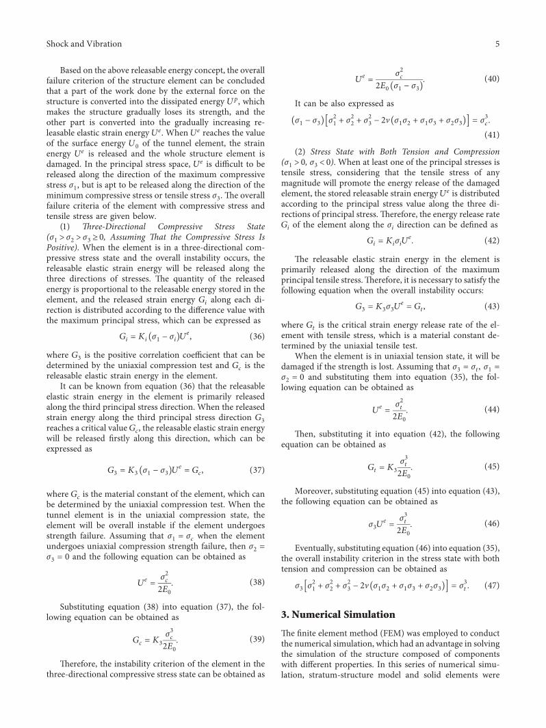
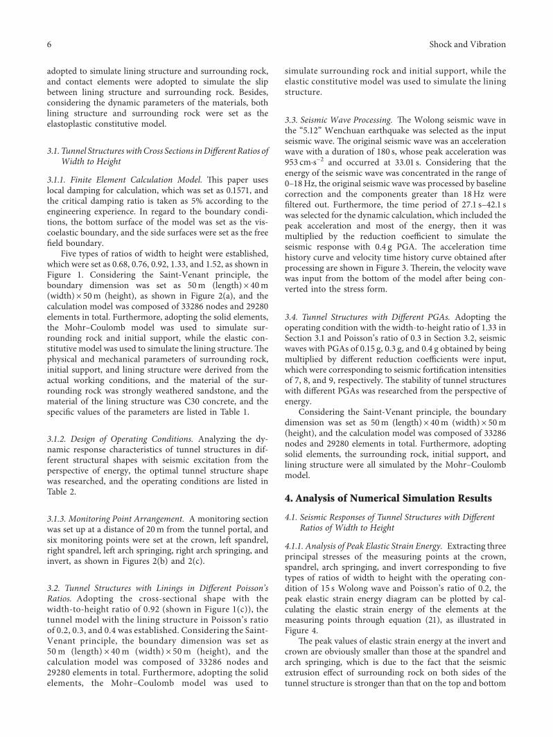
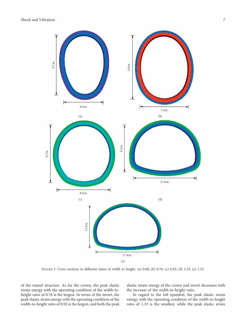
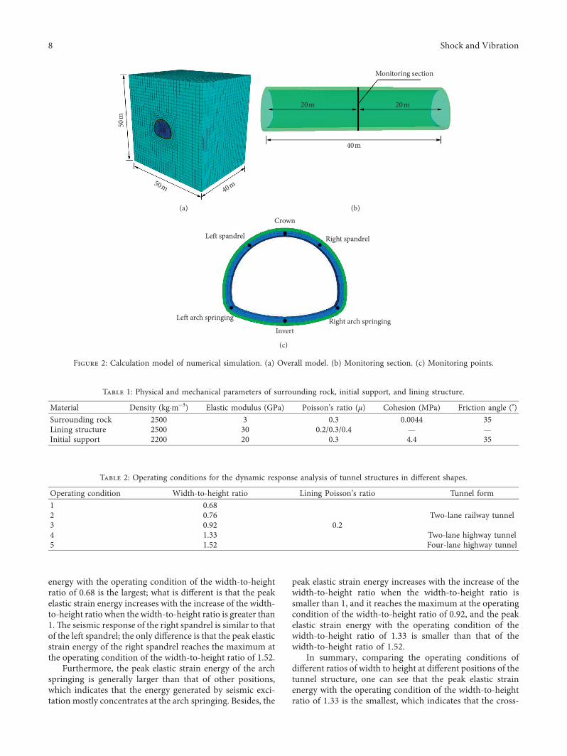
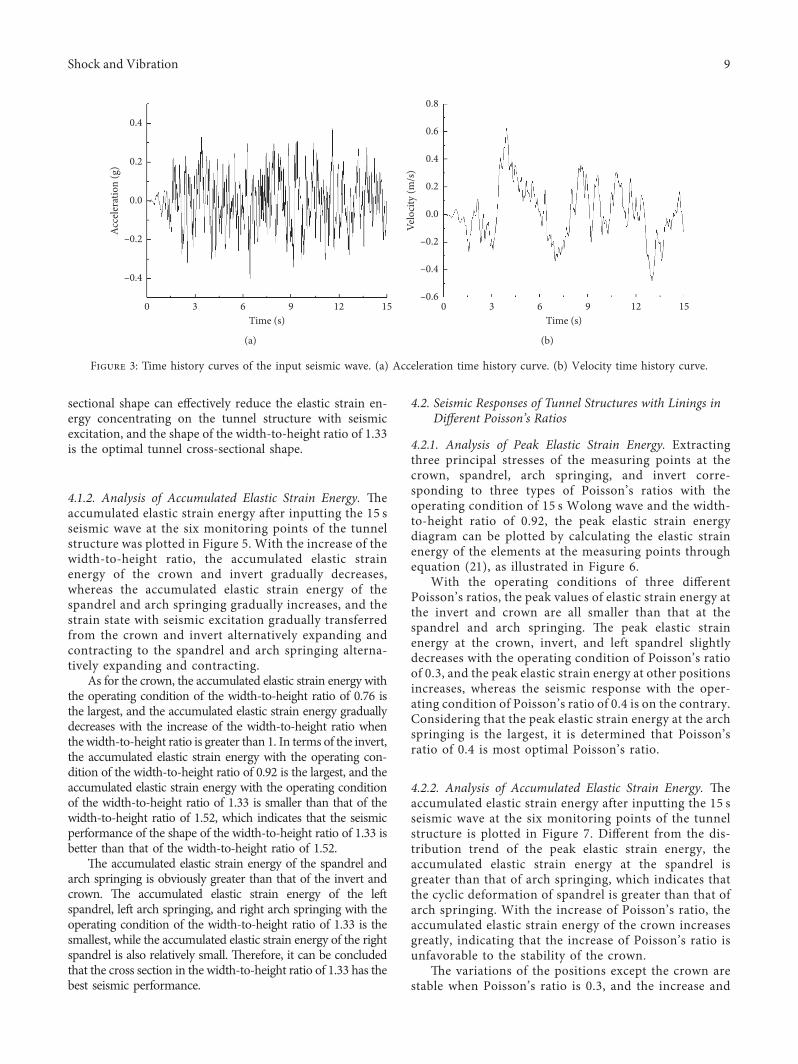
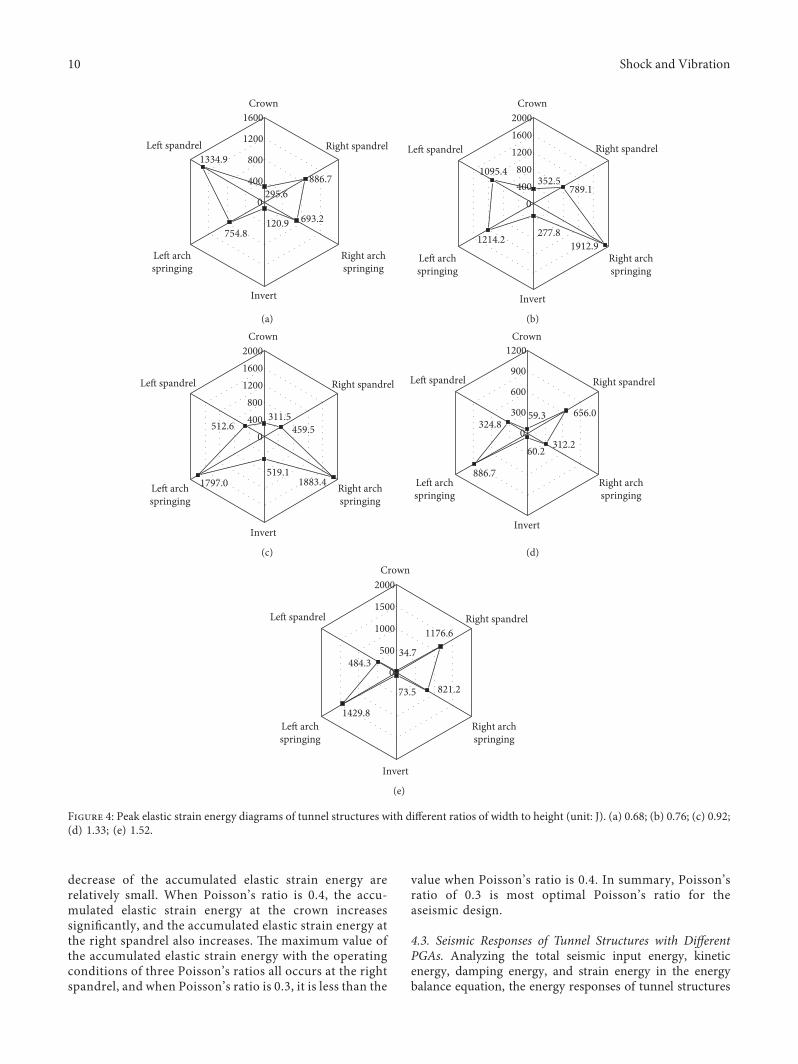
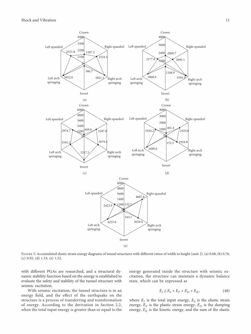
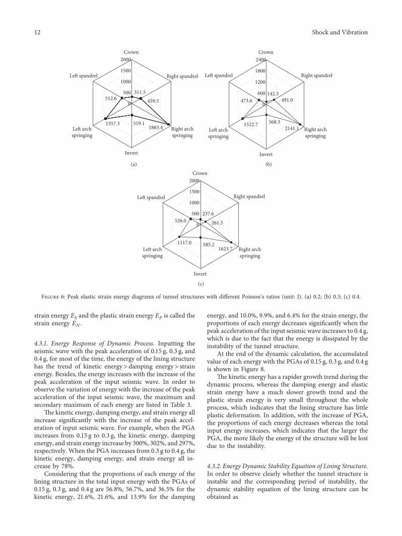
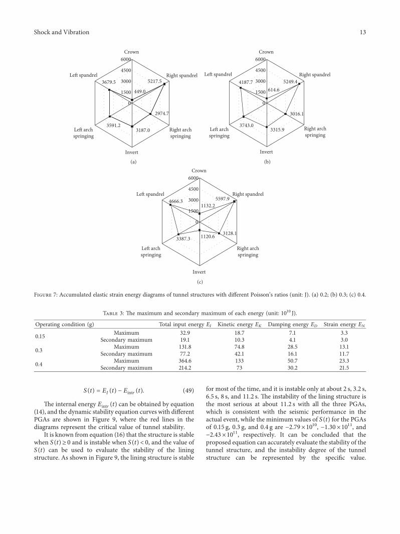
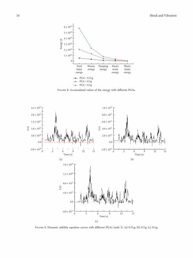
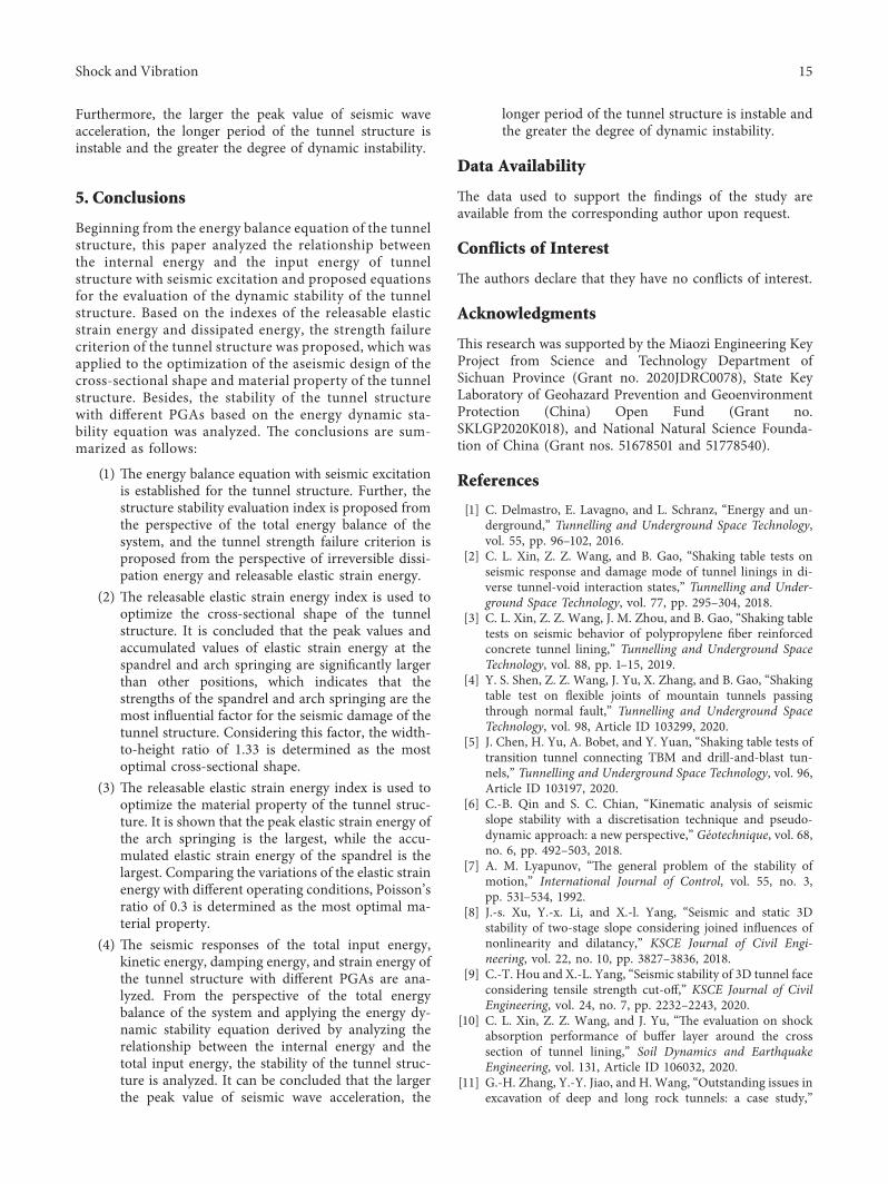
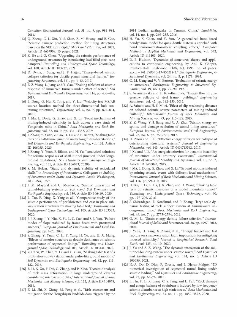