Embed Size (px)
Citation preview
BROWNSVILLE NAVIGATION DISTRICT
BULK CARGO DOCK IMPROVEMENTS
STRUCTURAL STEEL SPECIFICATION
Rev Description Date Prepared Reviewed Approved Client B Issued for Bid 05/07/2018 TMB MDP DRK
EDG Job No. 6966.003 EDG Document No. 6966003-40900-00001

Port of Brownsville Brownsville, Texas Bulk Cargo Dock Improvements Structural Steel Specification
6966003-40900-00001-B-StructuralSteel.docx Page 2 of 13
Change Log
REV SECTION CHANGE DESCRIPTION
A - None – First Issuance
B - Issued for Bid
Document Holds
REV SECTION CHANGE DESCRIPTION
A - None
B - None
Port of Brownsville Brownsville, Texas Bulk Cargo Dock Improvements Structural Steel Specification
6966003-40900-00001-B-StructuralSteel.docx Page 3 of 13
TABLE OF CONTENTS
1.0 GENERAL ............................................................................................................ 4
1.1. Scope of Work .......................................................................................... 4
1.2. Applicable Standards and Codes ........................................................... 4
1.3. Qualifications ........................................................................................... 4
1.4. Shop Drawings ......................................................................................... 5
2.0 PRODUCTS ......................................................................................................... 5
2.1. Materials ................................................................................................... 5
3.0 EXECUTION ......................................................................................................... 7
3.1. Fabrication ............................................................................................... 7
3.2. Material Handling ..................................................................................... 8
3.3. Material Preparation ................................................................................ 9
3.4. Cleaning and Painting ............................................................................. 9
3.5. Erection .................................................................................................... 9
3.6. Welding ................................................................................................... 10
3.7. Rework and Fairing................................................................................ 11
3.8. Weld Inspection ..................................................................................... 11
3.9. Completion ............................................................................................. 13
Port of Brownsville Brownsville, Texas Bulk Cargo Dock Improvements Structural Steel Specification
6966003-40900-00001-B-StructuralSteel.docx Page 4 of 13
1.0 GENERAL
1.1. Scope of Work
The provisions of this section are applicable to all the structural steel, miscellaneous metal work, and steel items required to complete the work as shown on the Contract Drawings and as outlined in the Specifications.
1.2. Applicable Standards and Codes
A. Comply with requirements of the latest edition of the following standards (including all supplements and addenda), unless noted otherwise:
1. American Institute of Steel Construction (AISC):
a. “Steel Construction Manual” - Fourteenth Edition
b. “Detailing for Steel Construction” – Third Edition
c. “Code of Standard Practice for Steel Buildings and Bridges”
d. “Allowable Stress Design Specification for Structural Joints Using A325 or A490 Bolts”
2. American Welding Society "Structural Welding Code" (AWS D1.1).
3. 2012 International Building Code.
4. “Minimum Design Loads for Buildings and Other Structures” (ASCE/SEI 7-10).
5. “Building Code Requirements for Structural Concrete and Commentary” (ACI 318-11).
6. American Society for Testing and Materials (ASTM) – Applicable Referenced Specifications.
7. Occupational Safety and Health Administration (OSHA) – As required by State and Federal Regulations.
B. Where provisions of pertinent codes and standards conflict with these Specifications, the more stringent provisions shall govern.
1.3. Qualifications
A. Steel fabricator shall be a member of the American Institute of Steel Construction or approved by Owner’s Representative, who can further demonstrate at least ten (10) years of qualified experience.
Port of Brownsville Brownsville, Texas Bulk Cargo Dock Improvements Structural Steel Specification
6966003-40900-00001-B-StructuralSteel.docx Page 5 of 13
B. Qualify welding procedures, welders and welding operators in accordance with AWS D1.1. Only certified welders shall perform the work.
C. The Fabricator is required to obtain mill certificates from the supplier for all structural steel and furnish copies of the certificates to the Owner’s Representative. The certificates shall be maintained in an orderly file and cross-referenced to the specific area of the project into which the steel was included in fabrication.
1.4. Shop Drawings
A. Prepare Shop Drawings in accordance with the latest edition of the AISC manual “Structural Steel Detailing.”
1. Include diameters of bolt holes; types, sizes and strengths of bolts; yield strength of steel; shop and field welding details; arc-welding electrode designation; and manufacturer’s name, color, and number of coats of shop paint.
2. Include erection diagrams showing elevations and cross sections, which will locate all members by piece mark and provide essential dimensions and necessary erection information.
3. Design all connections not shown on the Contract Drawings. Design of connections shall be as outlined on the Contract Drawings.
4. Substitution of sections or modification of details will not be accepted unless approved in writing by the Owner’s Representative.
B. Do not start fabrication until approval of shop drawings from Owner’s representative is received.
2.0 PRODUCTS
2.1. Materials
A. Bars, Plates and Shapes
1. Structural rolled shapes shall conform to ASTM A36, A572 Grade 50 or A992. Structural plates shall conform to ASTM A36 or A572 Grade 50. Wide flange (W) shapes shall conform to ASTM A992.
2. All structural steel bars, plates and shapes shall conform to ASTM A6 “General Requirements for Rolled Structural Steel Bars, Plates, Shapes and Sheet Piling.”
3. Plates shall be produced from cut lengths of flat product. Plates produced from coil are specifically disallowed. Plates shall be purchased oversized and cut to fabricated dimensions or purchased
Port of Brownsville Brownsville, Texas Bulk Cargo Dock Improvements Structural Steel Specification
6966003-40900-00001-B-StructuralSteel.docx Page 6 of 13
with sheared, gas, or plasma cut edges in exact sizes. Mill edge plates are not to be used in fabrication.
B. Bolts, Nuts, and Washers
1. All bolts not with vendor-furnished equipment packages shall conform to the following ASTM Designations: A307, A449, F3125 Grade A325 or A490, A563, and as indicated in the Contract Drawings. Nuts shall be ASTM A563 heavy hex nuts. Washers shall conform to ASTM F436. Where necessary, bolts may be purchased under the equivalent SAE specification of grade 8 if mechanical properties are shown to be equivalent. All bolts, nuts and washers shall be galvanized.
2. All bolts shall be of the size indicated in the Contract Drawings and shall be UNC coarse thread series. Nuts shall be heavy hex series and fitted with hardened washers, lock washers, or other washers as indicated on the Contract Drawings.
3. All bolts, nuts, and threaded holes in structural steel shall be thoroughly cleaned of any foreign matter including machining chips and oil before the bolts are installed. The threaded portion of the bolt to engage with the nut and/or the threaded steel shall be coated with a thread-locking compound suitable for disassembly with hand tools.
4. The minimum number of lines of bolts in any connection shall be two.
5. Beveled washers shall be used on all tapered flanges.
6. Bolts shall be of proper length to permit full thread in the nut, but shall not project more than ¼” beyond the face of the nut.
C. Welding Electrodes
1. Welding electrodes shall conform to ANSI/AWS with a minimum electrode tensile strength of 70 ksi.
D. Threaded Rods and Anchor Bolts
1. Threaded rods, nuts, and couplings shall be Grade 75, and they shall meet the strength requirements of ASTM A615.
2. Anchor Bolts shall meet the strength requirements of ASTM F1554 Grade 36, 55, or 105 as noted on the Contract Drawings.
Port of Brownsville Brownsville, Texas Bulk Cargo Dock Improvements Structural Steel Specification
6966003-40900-00001-B-StructuralSteel.docx Page 7 of 13
3.0 EXECUTION
3.1. Fabrication
A. Fabricate items of structural steel in accordance with AISC Specifications and as indicated on the approved Shop Drawings. Provide camber in structural members as shown.
B. Properly mark and match-mark materials for field assembly and for identification as to structure and site for which intended. Fabricate for delivery sequence that will expedite erection and minimize field handling of materials.
C. Furnish main steel members in one piece without splicing, unless noted otherwise on Contract Drawings approved by the Owner and/or Owner’s Representative.
D. Weld acceptance criteria shall be per AWS requirements. Remove all defects and reweld as required.
E. Contractor to verify all existing dimensions and elevations before fabrication. The completed structure shall be dimensionally accurate to the extent that parts shall move and function freely without unnecessary strain, wear, vibration or deflections.
F. In regard to items not indicated on the Contract Drawings or referenced in the Specifications or Design, the requirements of the AISC Code of Standard Practice for Steel Buildings and Bridges shall govern.
G. General dimensional tolerances not specified on the Contract Drawings shall meet the requirements of the AISC Code of Standard Practice for Steel Buildings and Bridges. Dimensional tolerances for fitting at joints to be welded shall meet the requirements of AWS D1.1 for pre-qualified and/or Fabricator-qualified welding procedures.
H. All workmanship must be first-class in all respects, and any exposed members not presenting a finished and workmanlike appearance will be rejected. All finished members shall be free from warps, twists, bends or open joints.
I. Faulty work shall be immediately corrected at no additional expense to the Owner and/or Owner’s Representative.
J. All members shall be true to length so that assembling may be done without fillers, except where fillers are required as detailed. There shall be no projecting edges or corners where different members are assembled.
K. All coping, blocking and mitering shall be done with care. Copes, blocks and cuts shall be per recommended practice of AISC “Steel Construction Manual” 14th Ed.
Port of Brownsville Brownsville, Texas Bulk Cargo Dock Improvements Structural Steel Specification
6966003-40900-00001-B-StructuralSteel.docx Page 8 of 13
L. All welds on exposed surfaces shall be smooth and flush with the adjacent surfaces.
M. All details and connections shall be carefully made and fitted to produce a thoroughly neat and workmanlike appearance. All detail pieces shall be made in accordance with Shop Drawings and all projecting corners clipped and all filler pieces made flush.
N. Provide all lugs, clips, connections, bolts and the like, necessary for complete fabrication and erection, and to engage with the adjacent construction. Provide setting diagrams for loose items to be built into concrete work indicating location, elevation and projection of loose items.
O. Burning shapes to length in the shop with a standard flame-cutting machine will be permitted. There shall be no burning in the field without the consent of the Owner and/or Owner’s Representative. If consent is given, burned members shall be finished to an acceptable appearance, which shall be the equal of a sheared finish.
P. Cut, drill, bore or punch holes for bolts, pins and miscellaneous attachments. Drill holes in bearing plates. Flame burning is not allowed to cut holes or enlarge holes in structural steel with the exception of using flame burning to remove excessive material prior to finishing the parts with machine tools. Burning of holes will not be permitted in the shop.
3.2. Material Handling
A. Where possible, material shall be handled with slings, straps, and/or plate clamps to minimize the attachment of welded plate clips and lifting lugs to the structure. Where necessary, lifting clips, eyes, and lugs may be fitted on a temporary basis and removed after member erection. Where this course is followed, the base material shall be refinished to original surface condition by welding gouges and grinding surface irregularities to a flush, finished condition.
B. In areas where lifting lugs may be left on the structure without detriment to the function or appearance to the structure, the Fabricator shall be permitted to leave the lifting attachments permanently in place. The attachments shall be welded continuously and shall receive surface preparation and protective coating systems identical to the surrounding structure to which they are attached.
C. Material shall be stored so as to avoid contact with the ground, exposure to corrosive environment, weld splatter, or other conditions that will adversely affect the milled surface finish on the material to be used in fabrication. Material shall be protected against weathering. Material shall be stored in a manner to insure that no members, protruding flanges, stiffeners, gussets plates, and other attachments are bent or otherwise damaged during storage.
Port of Brownsville Brownsville, Texas Bulk Cargo Dock Improvements Structural Steel Specification
6966003-40900-00001-B-StructuralSteel.docx Page 9 of 13
D. If such defects or damage in material cannot be corrected in the field to the entire satisfaction of the Owner and/or Owner’s Representative, the material shall be returned to the shop, or new parts furnished, as the Owner and/or Owner’s Representative will direct. The Contractor shall pay all expenses for such actions.
E. Material determined unacceptable by the Owner and/or Owner’s Representative shall be corrected or replaced as required, all at the Contractor’s expense.
3.3. Material Preparation
A. Material shall be carefully cut to length and dimensioned using optical or numerical burning equipment, saws, shears, etc. where possible. Material that is cut using hand torches shall be carefully ground to finished dimensions and to remove any edge irregularities prior to fabrication.
B. Individual parts shall be clearly marked with semi-permanent markers to indicate the steel grade from which the part has been fabricated.
3.4. Cleaning and Painting
A. Clean and coat all structural steel and other miscellaneous steel items as outlined in the Coating Specifications.
B. Do not shop coat:
1. Surfaces within 2 inches of field welds.
2. Surfaces to be galvanized.
C. After erection, erection contractor shall field paint all unpainted surfaces and abraded spots with primer and finish coats as outlined in Coating Specifications.
3.5. Erection
A. Brace and maintain all steel in alignment until other parts of construction necessary for permanent bracing or support are completed.
B. Erect steel fabrications plumb and true, in positions indicated. All work shall be formed, fabricated and erected or installed true to lines, levels, and dimensions, plumb and square. Level and plumb individual members of the structure within specified AISC tolerances.
C. All workmanship must be first-class in all respects, and any exposed members not presenting a finished and workmanlike appearance will be rejected. All finished members shall be free from warps, twists, bends, or open joints.
Port of Brownsville Brownsville, Texas Bulk Cargo Dock Improvements Structural Steel Specification
6966003-40900-00001-B-StructuralSteel.docx Page 10 of 13
D. Faulty work shall be immediately corrected at no additional expense to the Owner and/or Owner’s Representative.
3.6. Welding
A. General
1. Welding details shall conform to the size and configurations indicated on the Contract Drawings and Fabricator-prepared Shop Drawings.
2. All welding shall fully comply with the requirements of AWS D1.1 Structural Welding Code – Steel.
B. Welding Procedures
1. All standard procedures shall be pre-qualified or qualified under the requirements of AWS D1.1.
2. Formal written welding procedures shall be prepared by the Contractor and submitted to the Owner and/or Owner’s Representative for review prior to the commencement of fabrication. All procedures shall be either pre-qualified or qualified by the Fabricator on a case-by-case basis.
3. The formal welding procedures shall contain sketches indicating joint geometry; welding processes; base material specification and thickness limits; groove preparation dimensions and tolerances; permitted welding positions; rod, wire, flux and gas shield information; current type, range, and polarity; and preheat and interpass temperature ranges.
4. Welding procedures that are not pre-qualified by AWS D1.1 and qualified by the Fabricator shall be qualified in the presence of the Owner and/or Owner’s Representative.
5. Allowable welding processes are:
a. Shielded Metal Arc Welding (SMAW)
b. Gas Metal Arc Welding (GMAW)
c. Flux Core Arc Welding (FCAW)
d. Submerged Arc Welding (SAW)
6. Filler material requirements shall be per AWS.
7. Remove backing bars from all accessible complete joint penetration welds.
Port of Brownsville Brownsville, Texas Bulk Cargo Dock Improvements Structural Steel Specification
6966003-40900-00001-B-StructuralSteel.docx Page 11 of 13
C. Welding Operator Qualifications
1. Each welding operator shall be qualified on the process and filler material he will use during the fabrication of the structure. Operator qualification shall be in strict accordance with AWS D1.1.
2. An operator previously qualified on a particular process, position, and filler combination will not be required to re-qualify provided he or she meets the requirements of AWS D1.1, and the records required are available to the Owner and/or Owner’s Representative for examination.
3.7. Rework and Fairing
A. Fabricated steel that is out of dimensional tolerances and/or not fair to the eye shall be replaced and/or repaired at the Fabricator’s expense. If heat fairing shall be used, the material shall not be heated to more than 1200°F. During heat fairing procedures, the Fabricator shall monitor the material temperature with temp sticks or lacquer, surface applied thermocouple gauges, or some other suitable form of temperature measuring system.
3.8. Weld Inspection
A. Inspection of welded splices of main members and all complete penetration welds selected by the Contractor and submitted for approval by the Owner and/or Owner’s Representative shall be by a testing laboratory approved by the Owner and/or Owner’s Representative and paid for by the Contractor, unless noted otherwise in the Contract Documents. All weld testing shall be in accordance with the AWS.
B. The Contractor shall cooperate with and assist the Owner and/or Owner’s Representative with the inspection of welds.
C. Visual Inspection
1. The Fabricator’s quality control personnel and the Owner’s Representative shall visually inspect welding joint fit-up and preparation prior to the commencement of production welding. Joint fit-up details that are outside the tolerances listed in the appropriate welding procedures shall be repaired or replaced prior to the commencement of production welding.
2. The Fabricator’s quality control personnel and the Owner’s Representative shall visually inspect 100%-completed production welding immediately following its completion. Any irregularities such as undercuts, surface irregularities, etc. shall be repaired. Following any repairs required after visual inspection, the weld and adjacent parent material shall be thoroughly cleaned of any contamination such
Port of Brownsville Brownsville, Texas Bulk Cargo Dock Improvements Structural Steel Specification
6966003-40900-00001-B-StructuralSteel.docx Page 12 of 13
as weld flux, BB’s, etc. in preparation for non-destructive testing of welds.
D. Non-Destructive Testing (NDT)
1. General
a. The Contractor shall furnish non-destructive testing services for verifying weld quality. The personnel performing the testing shall be the employees of an independent testing firm suitable to the Fabricator and Owner and/or Owner’s Representative. The Owner’s Representative shall have the right to dismiss the independent testing firm if the quality of inspection services is deemed unsatisfactory. Upon this occurrence, another mutually suitable firm shall continue with the NDT procedures.
b. The NDT technicians shall be qualified in accordance with the current edition of the American Society for Non-Destructive Testing Recommended Practice No. SNT-TC-1A and shall be qualified for NDT Level II. All testing shall fully comply with the requirements of AWS D1.1, Chapter 6 “Inspection,” and the additional requirements stipulated herein.
c. The preparation and disposition of reports shall be as stipulated in AWS D1.1 unless the Owner and/or Owner’s Representative requests an alternative disposition.
2. Radiographic Testing (RT)
a. All complete penetration shop welds in main structural members shall be inspected using RT procedures that conform to the requirements of ASW D1.1, Chapter 6 Part B.
b. The acceptability criteria for flaws found in welds shall be as detailed in AWS D1.1.
3. Magnetic Particle Inspection (MPI)
a. MPI shall conform to the procedures and standards set forth in AWS D1.1 and ASTM E709.
4. Ultrasonic Testing (UT)
a. All complete penetration field welds shall be inspected using UT procedures.
b. Ultrasonic testing shall conform to the procedures and standards set forth in AWS D1.1, Ultrasonic Testing of Groove Welds.
Port of Brownsville Brownsville, Texas Bulk Cargo Dock Improvements Structural Steel Specification
6966003-40900-00001-B-StructuralSteel.docx Page 13 of 13
5. The Contractor shall correct improper workmanship and remove, replace, or correct as instructed all welds found unacceptable or deficient by the Owner and/or Owner’s Representative. The Contractor shall pay for all corrections. 3.9 Field Quality Control
3.9. Pile Tests and Inspections
A. Testing Agency: General Contractor will engage a qualified independent testing agency to perform tests and inspections.
B. Dynamic Pile Testing: High-strain dynamic monitoring shall be performed and reported according to ASTM D 4945 during initial driving and during restriking of 8% of the 30in diameter piles.
3.10. Completion
A. Upon completion or when directed, conduct careful inspection and correct all defective work.
B. Remove scrap, litter and debris resulting from operations specified herein, and leave work and the premises in clean satisfactory condition, ready to receive subsequent work.
END OF SECTION
BROWNSVILLE NAVIGATION DISTRICT
BULK CARGO DOCK IMPROVEMENTS
CAST-IN-PLACE CONCRETE SPECIFICATION
Rev Description Date Prepared Reviewed Approved Client B Issued for Bid 05/07/2018 TMB MDP DRK
EDG Job No. 6966.003 EDG Document No. 6966003-40900-00002
Port of Brownsville Brownsville, Texas Bulk Cargo Dock Improvements Cast-In-Place Concrete Specification
6966003-40900-00002-B-Cast-In-PlaceConcrete.docx Page 2 of 17
Change Log
REV SECTION CHANGE DESCRIPTION
A - None – First Issuance
B - Issued for Bid
Document Holds
REV SECTION CHANGE DESCRIPTION
A - None
B - None
Port of Brownsville Brownsville, Texas Bulk Cargo Dock Improvements Cast-In-Place Concrete Specification
6966003-40900-00002-B-Cast-In-PlaceConcrete.docx Page 3 of 17
TABLE OF CONTENTS
1.0 SCOPE ................................................................................................................. 4
2.0 QUALITY ASSURANCE ...................................................................................... 4
3.0 SUBMITTALS ...................................................................................................... 5
4.0 PROJECT CONDITIONS ..................................................................................... 6
5.0 DELIVERING AND STORING .............................................................................. 7
6.0 FORM MATERIALS ............................................................................................. 7
7.0 REINFORCING MATERIALS ............................................................................... 7
8.0 CONCRETE MATERIALS.................................................................................... 8
9.0 RELATED MATERIALS ....................................................................................... 8
10.0 PROPORTIONING AND DESIGN OF MIXES ...................................................... 9
11.0 CONCRETE MIXING .......................................................................................... 10
12.0 PLACING FORMS ............................................................................................. 10
13.0 PLACING REINFORCEMENT ........................................................................... 11
14.0 INSTALLATION OF EMBEDDED ITEMS .......................................................... 11
15.0 PREPARATION OF FORM SURFACES ........................................................... 11
16.0 CONCRETE PLACEMENT ................................................................................ 12
17.0 FINISH OF FORMED SURFACES ..................................................................... 13
18.0 TOP SURFACE FINISHES ................................................................................ 13
19.0 CONCRETE CURING AND PROTECTION ....................................................... 14
20.0 REMOVAL OF FORMS ...................................................................................... 15
21.0 RE-USE OF FORMS .......................................................................................... 15
22.0 MISCELLANEOUS CONCRETE ITEMS ........................................................... 15
23.0 CONCRETE SURFACE REPAIRS .................................................................... 15
Port of Brownsville Brownsville, Texas Bulk Cargo Dock Improvements Cast-In-Place Concrete Specification
6966003-40900-00002-B-Cast-In-PlaceConcrete.docx Page 4 of 17
1.0 SCOPE
1.1 This specification provides the Contractor with cast-in-place concrete requirements. The extent of concrete work required is shown on the project drawings and includes, but this is not limited to:
A. Formwork B. Reinforcing C. Placing Concrete D. Testing E. Finishing
2.0 QUALITY ASSURANCE
2.1 Comply with provisions of following codes, specifications and standards, except where more stringent requirements are shown or specified:
A. ACI 301 "Specifications for Structural Concrete for Buildings".
B. ACI 318 "Building Code Requirements for Structural Concrete”.
C. Concrete Reinforcing Steel Institute, "Manual of Standard Practice".
D. International Building Code 2012.
E. Keep one copy of the Field Reference Manual, ACI MNL-15 in the project office at all times during construction.
2.2 Concrete Testing Service: Employ at Contractor's expense a testing laboratory
acceptable to Owner to perform material evaluation tests and to design concrete mixes.
A. Following tests will be required:
1. Sampling: Per ASTM C172 2. Slump: Per ASTM C143, one (1) test for each load at point of
discharge. 3. Air Content: Per ASTM C173, one (1) test for each set of
compressive strength specimens. 2.3 Sampling Fresh Concrete: ASTM C172, except modified for slump to comply
with ASTM C94.
A. Slump: ASTM C143; one test for each concrete load at point of discharge; and one test for each set of compressive strength test specimens.
B. Air Content: ASTM C231 pressure for normal weight concrete; one for each set of compressive strength test specimens.
Port of Brownsville Brownsville, Texas Bulk Cargo Dock Improvements Cast-In-Place Concrete Specification
6966003-40900-00002-B-Cast-In-PlaceConcrete.docx Page 5 of 17
C. Concrete Temperature: Test hourly when air temperature is 40 degrees F (4 degrees C) and below, and when 80 degrees F (27 degrees C), and above; and each time a set of compression test specimens made.
D. Compression Test Specimen: ASTM C31; one set of 6 standard cylinders for each compressive strength test, unless otherwise directed. Mold and store cylinders for laboratory cured test specimens except when field-cure test specimens are required.
E. Compressive Strength Tests: ASTM C39; one set for each 100 cu. yds. or fraction thereof, or 2500 sq. ft. of slab, of each concrete class placed in any one day; 2 specimens tested at 7 days, 3 specimens tested at 28 days, and 1 specimen retained in reserve for later testing if required.
F. When frequency of testing will provide less than 5 strength tests for a given class of concrete, conduct testing from at least 5 randomly selected batches or from each batch if fewer than 5 are used.
G. When strength of field-cured cylinders is less than 85% of companion laboratory-cured cylinders, evaluate current operations and provide corrective procedures for protecting and curing the in-place concrete.
H. Strength level of concrete will be considered satisfactory if averages of sets of three consecutive strength test results equal or exceed specified compressive strength, and no individual strength test result falls below specified compressive by more than 500 psi.
2.4 Test results will be reported in writing to Owner and Contractor on same day that
tests are made. Reports of compressive strength tests shall contain the project identification name and number, date of concrete placement, name of concrete testing service, concrete type and class, location of concrete mix proportions and materials; compressive breaking strength and type of break for both 7-day tests and 28-day tests.
2.5 Additional Tests: The testing service will make additional tests of in-place concrete when test results indicate specified concrete strengths and other characteristics have not been attained in the structure, as directed by Owner. Testing service may conduct tests to determine adequacy of concrete by cored cylinders complying with ASTM C42, or by other methods as directed. Contractor shall pay for such tests conducted, and any other additional testing as may be required, when unacceptable concrete is verified.
3.0 SUBMITTALS
3.1 Product Data: Submit data for all materials and items, including cement, aggregates, water, mix design, reinforcement, forming accessories, admixtures, patching compounds, water stops, joint systems, curing compounds, finish materials, and others for Owner review.
Port of Brownsville Brownsville, Texas Bulk Cargo Dock Improvements Cast-In-Place Concrete Specification
6966003-40900-00002-B-Cast-In-PlaceConcrete.docx Page 6 of 17
3.2 Shop Drawings - Reinforcing
A. Meet requirements of applicable portions of "Details and Detailing of Concrete Reinforcement" by ACI 315, latest edition.
B. Show bending, assembly, splicing, sizes, bar lengths, quantity and marking of
bars. Indicate bar spacing by dimension. C. Show wall, column, and beam reinforcing with necessary details in elevation.
Show slab reinforcing, with necessary details, in plan. Locate sleeves, holes, accessories, and anchors by dimensions.
D. Furnish prints of approved shop drawings to trades that have items to be
embedded in, or connected to concrete work. E. Do not use Engineer’s drawings as base sheets for shop drawings.
3.3 Samples: Submit samples of materials as requested by Owner’s Representative,
including names, sources, and descriptions.
3.4 Laboratory Test Results: Submit laboratory test reports for concrete materials and mix design test.
3.5 Material Certificates: Provide materials certificates/mill reports in lieu of materials laboratory test reports when permitted by Owner’s Representative. Materials certificates shall be signed by manufacturer and Contractor, certifying that each material item complies with, or exceeds, specified requirements. Provide certificates from admixture manufacturers that chloride content complies with specification requirements.
4.0 PROJECT CONDITIONS
4.1 Comply with applicable requirements of "Cold Weather Concreting", ACI 306R-16, and "Hot Weather Concreting", ACI 305R-10.
4.2 Do not place concrete if temperature is below 40 degrees F or shows signs to be below 40 degrees F within the set time of the pour. except with specific approval, and then be prepared to provide heat to maintain concrete temperature as recommended in ACI 306R-16.
4.3 Reduce concrete temperatures to prevent rapid evaporation of water in hot weather.
4.4 Protect persons from injury and property from damage. Satisfactorily repair or remove and replace work that has been damaged.
Port of Brownsville Brownsville, Texas Bulk Cargo Dock Improvements Cast-In-Place Concrete Specification
6966003-40900-00002-B-Cast-In-PlaceConcrete.docx Page 7 of 17
5.0 DELIVERING AND STORING
5.1 Deliver unopened, packaged materials to site in manufacturer's original labeled containers. Schedule deliveries to avoid delays and to prevent greater accumulations that can be suitably store at site.
5.2 Arrange deliveries to provide sufficient quantities to permit continuity of placing for any phase of work. Do not change suppliers or brands for any phase of work, without specific approval.
5.3 Store materials to prevent damage to other materials or to structure. Store cementitious material in dry, weathertight, ventilated spaces. Store aggregates to exclude foreign matter and to maintain gradation. Do not store reinforcing in contact with the ground.
5.4 Laboratory Tests: Submit laboratory test reports for concrete materials and mix design test as specified.
5.5 Samples: Submit samples of materials as specified and as otherwise required by Owner, including names, sources and descriptions.
6.0 FORM MATERIALS
6.1 Forms for Exposed Concrete: Provide plywood, metal framed plywood or other acceptable panel-type materials.
6.2 Use plywood complying with U.S. Product Standard PS-1 "B-B (Concrete Form) Plywood", Class I, Exterior Grade or better, mill-oiled and edge-sealed, with each piece bearing legible inspection trademark.
6.3 Forms for Unexposed Concrete: Provide plywood, lumber, metal or other acceptable material. Provide lumber dressed or at least 2 edges and one side for tight fit.
6.4 Form Coatings: Provide commercial formulation form-coating compounds that will not bond with, stain nor adversely affect concrete surfaces, and will not impair subsequent treatments of concrete surfaces.
7.0 REINFORCING MATERIALS
7.1 Reinforcing Bars: ASTM A615, or A706, Grade 60 deformed.
7.2 Steel Wire: ASTM A1064, plain, cold-drawn, steel.
7.3 Welded Wire Fabric: ASTM A1064, welded steel wire fabric.
7.4 Supports for reinforcement: Provide bolsters, chairs, spacers and other devices for spacing, supporting and fastening reinforcing bars and welded wire fabric in place. Use wire bar type supports complying with CRSI recommendations, with plastic tips or stainless steel.
Port of Brownsville Brownsville, Texas Bulk Cargo Dock Improvements Cast-In-Place Concrete Specification
6966003-40900-00002-B-Cast-In-PlaceConcrete.docx Page 8 of 17
8.0 CONCRETE MATERIALS
8.1 Portland Cement: ASTM C150, Type II or Type IIA. Use one brand of cement throughout project.
8.2 Normal Weight Aggregates: ASTM C33, and as herein specified. Provide aggregates from a single source for exposed concrete.
8.3 Water: Potable.
8.4 Water-Reducing Admixture: ANSI/ASTM C494, Type A and contain not more than 1% chloride ions.
A. Available Products: Subject to compliance with requirements, products, which may be incorporated in the work include, but are not limited to, the following:
B. Products: Subject to compliance with requirements, provide one of the following:
1. "Pozzolith 322N"; Master Builders 2. "Plastocrete 160"; Sika Chemical Corporation
8.5 High-Range Water-Reducing Admixture (Super Plasticizer): ASTM C494, Type
F of the sulfonated melamine formaldehyde condensate based materials type and contain not more than 1% chloride ions.
8.6 Water-Reducing, Retarding Admixture: ASTM C494, Type D and contain not more than 1% chloride ions.
8.7 Calcium Chloride not permitted.
8.8 Fly Ash up to 15% by weight of cementitious materials may be used. Fly ash shall conform to ASTM C618, Class C or F.
9.0 RELATED MATERIALS
9.1 Non-Corrosive, Non-Stain, Non-Shrink cementious precision grout compliance with CRD-C-621. Acceptable products Crystex/Duragrout by L&M, Master-Flow 713 by Master Builders, 5 Star by U.S. Grout, and SikaGrout 212 by Sika.
9.2 Bonding Compound - Non-reversible acrylic. Everbond by L&M, Acryl 600 by Price Research, and SikaBond by Sika.
9.3 Epoxy Bonding Adhesive shall be used to eliminate cold joints, 2 part, 100% solids for use on DAMP or DRY surfaces. Acceptable products include: Bond-1 by Permagile Industries Inc., Hi-Mod by Sika and Epobond by L&M.
Port of Brownsville Brownsville, Texas Bulk Cargo Dock Improvements Cast-In-Place Concrete Specification
6966003-40900-00002-B-Cast-In-PlaceConcrete.docx Page 9 of 17
9.4 Form Release Agent - Shall be non-transferring, non-staining, and 100% chemically active. DeBond by L&M, Magic Coat by Nox-Crete, and Pro-Cote by Protex.
9.5 Curing:
A. Moisture-Retaining Cover: Waterproof paper or a polyethylene film complying with ANSI/ASTM C171.
B. Liquid Membrane-Forming Curing Compound: Liquid type membrane-forming compound complying with ANSI/ASTM C309, Type I, Class A with minimum 30% solids content unless other type acceptable to Engineer.
C. Products: Subject to compliance with requirements, provide one of the
following:
1. "Masterseal"; Master Builders 2. "Clear Seal"; W.R. Grace 3. "Kure-N-Seal"; Sonneborn-Contech 4. "L&M Cure"; L & M Construction Chemicals 5. "Hardtop"; Gifford-Hill
10.0 PROPORTIONING AND DESIGN OF MIXES
10.1 Mix design for each strength of concrete required shall be prepared by an independent testing laboratory and submitted to the Owner Representative for approval. No concrete shall be poured until Owner Representative approval has been received.
10.2 Design mixes to provide normal weight concrete with the following properties, as indicated on drawings and schedules:
A. 5000 psi 28-day compressive strength
10.3 Adjustment to Concrete Mixes: Mix design adjustment may be requested by Contractor when characteristics of materials, job conditions, weather, test results, or other circumstances warrant as approved by and at no additional cost to Owner. Laboratory test data for revised mix design and strength results must be submitted to and accepted by Owner Representative before using in work.
10.4 Slump Limits: Proportion and design mixes to result in concrete slump at point of placement as follows:
A. Without water reducing admixture: Not less than 1" and not more than 3".
B. Concrete containing HRWR admixture (super plasticizer): Not more than 8".
Port of Brownsville Brownsville, Texas Bulk Cargo Dock Improvements Cast-In-Place Concrete Specification
6966003-40900-00002-B-Cast-In-PlaceConcrete.docx Page 10 of 17
11.0 CONCRETE MIXING
11.1 Ready-Mix Concrete: Comply with requirements of ASTM C94, and as herein specified.
A. Do not add additional water to the batch without the approval of the Owner’s Representative.
11.2 During hot weather, or under conditions contributing to rapid setting of concrete,
a shorter mixing time than specified in ASTM C94 may be required.
A. When air temperature is between 85 degrees F (30 degrees c) and 90 degrees F (32 degrees C) reduce mixing and delivery time from 1-1/2 hours to 75 minutes, and when air temperature is above 90 degrees F. (30 degrees C) reduce mixing and delivery time to 60 minutes.
12.0 PLACING FORMS
12.1 Design, erect, support, brace and maintain formwork to support all vertical and lateral loads that might be applied until such loads can be supported by concrete structures.
12.2 Construct forms complying with ACI 347, to sizes, shapes, lines and dimensions shown, and to obtain accurate alignment, location, grades, level, and plumb work in finished structures. Provide for openings, offsets, sinkages, keyways, recesses, moldings, rustications, reglets, chamfers, blocking, screeds, bulkheads, anchorages, inserts, and other features required in work. Use selected materials to obtain required finishes. Solidly butt joints and provide back-up at joints to prevent leakage of cement paste.
12.3 Fabricate forms for easy removal without hammering or prying against concrete surfaces. Provide crush plates or wrecking plates where stripping may damage cast concrete surfaces.
12.4 Provide 1” chamfer at all exposed corners and edges as indicated, using wood, metal PVC or rubber chamfer strips fabricated to produce uniform smooth lines and tight edge joints.
12.5 Form Ties: Factory-fabricated, adjustable-length, removable or snapoff metal form ties, designed to prevent form deflection, and to prevent spalling concrete surfaces upon removal.
A. Provide ties so portion remaining within concrete after removal is at least 1-1/2" inside concrete and which will not leave holes larger than 1" diameter in concrete surfaces.
12.6 Provisions for other trades: Provide openings/embedments in concrete formwork
to accommodate work of other trades. Accurately place and securely support
Port of Brownsville Brownsville, Texas Bulk Cargo Dock Improvements Cast-In-Place Concrete Specification
6966003-40900-00002-B-Cast-In-PlaceConcrete.docx Page 11 of 17
items built into forms. Contractor to verify opening/embedment locations with Certified Vendor Data as required.
12.7 Cleaning and Tightening: Thoroughly clean forms and adjacent surfaces to receive concrete. Remove chips, wood, sawdust, dirt or other debris just before concrete is placed.
13.0 PLACING REINFORCEMENT
13.1 Comply with Concrete Reinforcing Steel Institute's recommended practice for "Placing Reinforcing Bars", for details and methods of reinforcement placement and supports, and as herein specified.
13.2 Clean reinforcement of loose rust and mill scale, earth, ice and other materials which reduce bond with concrete.
13.3 Accurately position, support and secure reinforcement against displacement by formwork construction, or concrete placement operations. Locate and support reinforcing by metal chairs, runners, bolsters, spacers, and hangers, as required.
13.4 Place reinforcement to obtain at least minimum coverage for concrete protection. Arrange, space, and securely tie bars and bar supports to hold reinforcement in position during concrete placement operations. Set wire ties so ends are directed into concrete, not toward exposed concrete surfaces.
13.5 Provide corner bars at corners to match horizontal reinforcing, with minimum length of each leg 45 bar diameters. Show bars on Shop Drawings.
13.6 Lap all reinforcing bars at points of low stress, in accordance with ACI 318 and ACI 315, or as noted on the drawings. Show all splices on Shop Drawings.
14.0 INSTALLATION OF EMBEDDED ITEMS
14.1 Set and build into forms anchorage devices and other embedded items required for other work that is attached to, or supported by, cast-in-place concrete. Use setting drawings, diagrams, instructions and directions provided by suppliers of items to be attached thereto.
14.2 Edge Forms and Screed Strips and Slabs: Set edge forms or bulkheads and intermediate screed strips for slabs to obtain required elevations and contours in finished slab surface. Provide and secure units sufficiently strong to support types of screed strips by use of strike-off templates or accepted compacting type screeds.
15.0 PREPARATION OF FORM SURFACES
15.1 Coat contact surfaces of forms with a form-coating compound before reinforcement in places.
Port of Brownsville Brownsville, Texas Bulk Cargo Dock Improvements Cast-In-Place Concrete Specification
6966003-40900-00002-B-Cast-In-PlaceConcrete.docx Page 12 of 17
A. Thin form-coating compounds only with thinning agent of type, and in amount, and under conditions of form-coating compound manufacturer's directions.
B. Do not allow excess form-coating materials to accumulate in forms or to come into contact with concrete surfaces against which fresh concrete will be placed. Apply in compliance with manufacturer's instructions.
15.2 Coat steel forms with a non-staining, rust-preventative form oil or otherwise
protect against rusting. Rust-stained steel formwork is not acceptable.
16.0 CONCRETE PLACEMENT
16.1 Pre-placement Inspection, inspect formwork installation, and reinforcing steel for completeness. Notify Owner’s Representative at least 5 days before concrete pour to allow inspection. Notify other crafts to permit installation of their work; cooperate with other trades in setting such work. Moisten woods forms immediately before placing concrete where form coatings are not used.
16.2 Coordinate the installation of joint materials and moisture barriers with placement of forms and reinforcing steel.
16.3 Comply with ACI 304 and as herein specified.
16.4 Deposit concrete continuously or in layers of such thickness that no concrete will be placed on concrete which has hardened sufficiently to cause the formation of seams or planes of weakness. If a section cannot be placed continuously, provide construction joints as herein specified. Deposit concrete as nearly as practicable to its final location to avoid segregation.
16.5 Placing Concrete in Forms in horizontal layers not deeper than 24" and in a manner to avoid inclined construction joints. Where placement consists of several layers, place each layer while preceding layer is still plastic to avoid cold joints.
16.6 Consolidate placed concrete by mechanical vibrating equipment supplemented by hand-spading, rodding or tamping. Use equipment and procedures for consolidation of concrete in accordance with ACI recommended practices.
16.7 Do not use vibrators to transport concrete inside forms. Insert and withdraw vibrators vertically at uniformly spaced locations not farther than visible effectiveness of machine. Place vibrators to rapidly penetrate placed layer and at least 6" into preceding layer. Do not insert vibrators into lower layers of concrete that have begun to set. At each insertion limit duration of vibration to time necessary to consolidate concrete and complete embedment of reinforcement and other embedded items without causing segregation of mix.
16.8 Consolidate concrete during placing operation so that concrete is thoroughly worked around reinforcement and other embedded items and into corners.
Port of Brownsville Brownsville, Texas Bulk Cargo Dock Improvements Cast-In-Place Concrete Specification
6966003-40900-00002-B-Cast-In-PlaceConcrete.docx Page 13 of 17
16.9 Bring finished surfaces to correct level with straightedge and strikeoff. Use bull floats or darbies to smooth surface, free of humps or hollows. Do not disturb slab surfaces prior to beginning finishing operations.
16.10 Maintain reinforcing in proper position during concrete placement operations.
16.11 Hot Weather Placing: When hot weather conditions exist that would seriously impair quality and strength of concrete, place concrete in compliance with ACI 305R-10.
16.12 Cool ingredients before mixing to maintain concrete temperature at time of placement below 90 degrees F (32 degrees C). Mixing water may be chilled, or chopped ice may be used to control temperature provided water equivalent of ice is calculated to total amount of mixing.
16.13 Cover reinforcing steel with water-soaked retarding admixture (Type D) when required by high temperatures, low humidity or other adverse placing conditions.
17.0 FINISH OF FORMED SURFACES
17.1 Rough Form Finish (RfFm-Fn): For formed concrete surfaces not exposed-to-view in the finished work, unless otherwise indicated. Tie holes and defective areas shall be repaired and patched and fins and other projections exceeding 1/4" in height rubbed down or chipped off.
17.2 Smooth Form Finish (SmFm-Fn): For formed concrete surfaces exposed-to-view, or that are to be covered with a coating material applied directly to concrete, or a covering material applied directly to concrete, such as waterproofing, dampproofing, painting or other similar system. Obtained with selected form facing material, arranged orderly and symmetrically with a minimum of seams. Repair and patch defective areas with fins or other projections completely removed and smoothed.
17.3 Related Unformed Surfaces: At tops of walls, horizontal offsets surfaces occurring adjacent to formed surfaces, strike-off smooth and finish with a texture matching adjacent formed surfaces. Continue final surface treatment of formed surfaces uniformly across adjacent unformed surfaces.
18.0 TOP SURFACE FINISHES
18.1 Non-Slip Broom Finish (NSBrm-Fn): Apply non-slip broom finish to all walking surfaces.
A. Immediately after trowel finishing, slightly roughen concrete surface by brooming with fiber bristle broom perpendicular to main traffic route. Coordination required final finish with Owner’s Representative before application.
Port of Brownsville Brownsville, Texas Bulk Cargo Dock Improvements Cast-In-Place Concrete Specification
6966003-40900-00002-B-Cast-In-PlaceConcrete.docx Page 14 of 17
19.0 CONCRETE CURING AND PROTECTION
19.1 General: Protect freshly placed concrete from premature drying and excessive cold or hot temperatures.
A. Start initial curing as soon as free water has disappeared from concrete surface after placing and finishing. Weather permitting; keep continuously moist for not less than 72 hours.
B. Continue final curing for at least 7 days in accordance with ACI 301 procedures. Avoid rapid drying at end of final curing period.
19.2 Curing Methods: Perform curing of concrete by moist curing, by moisture-
retaining cover or by membrane curing.
19.3 Provide moisture curing by following methods:
A. Continuous water-fog spray.
B. Covering concrete surface with specified absorptive cover, thoroughly saturating cover with water and keeping continuously wet. Place absorptive cover to provide coverage of concrete surfaces and edges with 4" lap over adjacent absorptive covers.
19.4 Provide moisture-curing as follows:
A. Cover concrete surfaces with moisture-retaining cover for curing concrete, placed in widest practicable width with sides and ends lapped at least 3" and sealed by waterproof tape or adhesive. Immediately repair any holes or tears during curing period using cover material and waterproof tape.
19.5 Provide curing compound to horizontal exposed surfaces as follows:
A. Apply specified curing and sealing compound to concrete slabs as soon as final finishing operations are complete (within 2 hours). Apply uniformly in continuous operation by power-spray or roller in accordance with manufacturer's directions. Recoat areas subjected to heavy rainfall within 3 hours after initial application. Maintain continuity of coating and repair damage during curing period.
19.6 Curing Formed Surfaces: Leave forms in-place until concrete has obtained at
least 50% of design strength, then moist cure as per above.
19.7 Curing Unformed Surfaces: Cure unformed surfaces, such as slabs, floor topping, and other flat surfaces by application of appropriate curing method.
19.8 Final cure concrete surfaces to receive liquid floor hardener or finish flooring by use of moisture-retaining cover, unless otherwise directed.
Port of Brownsville Brownsville, Texas Bulk Cargo Dock Improvements Cast-In-Place Concrete Specification
6966003-40900-00002-B-Cast-In-PlaceConcrete.docx Page 15 of 17
19.9 Sealer and Dustproofer: Apply a second coat of specified curing and sealing compound only to surfaces given a first coat.
20.0 REMOVAL OF FORMS
20.1 Formwork not supporting weight of concrete, such as sides of beams, walls, columns and similar parts of the work, may be removed after cumulatively curing at not less than 50 degrees F (10 degrees C) for 24 hours after placing concrete, provide concrete is sufficiently hard to not be damaged by form removal operations, and provided curing and protection operations are maintained.
20.2 Formwork supporting weight of concrete, such as beam soffits, joints, slabs and other structural elements, may not be removed in less than 14 days and until concrete has attained design minimum compressive strength at 28-days. Determine potential compressive strength of in-place concrete by testing field-cured specimens representative of concrete location or members.
20.3 Form facing material may be removed 4 days after placement, only if shores and other vertical supports have been arranged to permit removal of form facing material without loosening or disturbing shores and supports.
21.0 RE-USE OF FORMS
21.1 Clean and repair surfaces of forms to be re-used in work. Split, frayed, delaminated or otherwise damaged form facing material will not be acceptable for exposed surfaces. Apply new form coating compound as specified for new formwork.
21.2 When forms are extended for successive concrete placement, thoroughly clean surfaces, remove fins and laitance, and tighten forms to close joints. Align and secure joint to avoid offsets. Do not use "patched" forms for exposed concrete surfaces, except as acceptable to Engineer.
22.0 MISCELLANEOUS CONCRETE ITEMS
22.1 Filling-In: Fill in holes and openings left in concrete structures for passage of work by other trades, unless otherwise shown or directed, after work of other trades is in place. Mix, place and cure concrete as herein specified, to blend with in-place construction. Provide other miscellaneous concrete filling shown or required to complete work.
22.2 Grout base plates and foundations indicated, using specified non-shrink, non-metallic grout.
23.0 CONCRETE SURFACE REPAIRS
23.1 Patching Defective Areas: Concrete repair and patching must be approved by Owner’s Representative prior to execution. Owner and Owner’s Representative reserves the right to have defective concrete work removed and replaced.
Port of Brownsville Brownsville, Texas Bulk Cargo Dock Improvements Cast-In-Place Concrete Specification
6966003-40900-00002-B-Cast-In-PlaceConcrete.docx Page 16 of 17
23.2 Cut out honeycomb, rock pockets, voids over 1/2" in any dimension, holes left by tie rods and bolts, down to solid concrete but, in no case to a depth of less than 1". Make edges of cuts perpendicular to the concrete surface. Thoroughly clean, dampen with water and brush-coat the area to be patched with specified bonding agent. Place patching mortar after bonding compound has dried. Patching shall take place as soon as practical after removal of forms.
23.3 For exposed-to-view surfaces, blend white portland cement and standard portland cement so that, when dry, patching mortar will match color surrounding. Provide test areas at inconspicuous location to verify mixture and color match before proceeding with patching. Compact mortar in place and strike-off slightly higher than surrounding surface.
23.4 Repair of Formed Surfaces: Remove and replace concrete having defective surfaces if defects cannot be repaired to satisfaction of Owner. Repair surface defects including color and texture irregularities, cracks, spalls, air bubbles, honeycomb, rock pockets; fins and other projections on surface; and stains and other discolorations that cannot be removed by cleaning. Flush out form tie holes, fill with dry pack mortar, or precast cement cone plugs secured in place with bonding agent.
23.5 Repair concealed formed surfaces, where possible, that contain defects that affect the durability of concrete. If defects cannot be repaired, remove and replace concrete.
23.6 Repair of Unformed Surfaces: Test unformed surfaces, such as exposed top horizontal surfaces, for smoothness and verify surface plane to tolerances specified for each surface and finish. Correct low and high areas as herein specified. Test unformed surfaces sloped to drain for trueness of slope, in addition to smoothness using a template having required slope.
23.7 Repair finish unformed surfaces that contain defects which affect durability of concrete. Repair surface defects, as such, cracks in excess of 0.001" wide or which penetrate to reinforcement or completely through non-reinforced section regardless of width, spalling, pop-outs, honeycomb, rock pockets, and other objectionable conditions.
23.8 Correct high areas in unformed surfaces by grinding, after concrete has cured at least 14 days.
23.9 Correct low areas in unformed surfaces during, or immediately after completion of surface finishing operations by cutting out low areas and replacing with fresh concrete. Finish repaired areas to blend into adjacent concrete. Proprietary patching compounds may be used when acceptable toOwner’s Representative.
23.10 Repair defective areas, except random cracks and single holes not exceeding 1" diameter, by cutting out and replacing with fresh concrete. Remove defective areas to sound concrete with clean, square cuts and expose reinforcing steel with at least 3/4" clearance all around. Dampen concrete surfaces in contact with
Port of Brownsville Brownsville, Texas Bulk Cargo Dock Improvements Cast-In-Place Concrete Specification
6966003-40900-00002-B-Cast-In-PlaceConcrete.docx Page 17 of 17
patching concrete and apply bonding compound. Mix patching concrete of same materials to provide concrete of same type or class as original concrete. Place compact and finish to blend with adjacent finished concrete. Cure in the same manner as adjacent concrete.
23.11 Repair isolated random cracks and single holes not over 1" diameter by dry-pack method. Groove top of cracks and cut-out holes to sound concrete and clean of dust, dirt, and loose particles. Dampen concrete surfaces in contact with patching concrete of same materials to provide concrete of same type or class as original concrete. Place compact and finish to blend with adjacent finish to blend with adjacent finish concrete.
23.12 Use the following specified applicable methods for conditions for COATING, PATCHING and REPAIRING.
A. Injection Applications - Contractor to have 5 years of experience and job references. Acceptable Epoxy Systems include: PERM-INJECT by Permagile Industries Inc. and Sikadur 52 Injection System by Sika. Others require written approval byOwner’s Representative.
B. Epoxy Grouting where shown or as required shall equal or exceed MMM-G-
650B CANC. Acceptable products include: 1-270 Epoxy Grout by Permagile Industries Inc. and approval by Owner’s Representative.
C. Epoxy Bonding Agents - Shall be moisture insensitive, 100% reactive solids, waterproof complying with ASTM C881. Manufacturer shall offer all grades and types. Acceptable products include: 1-215 HM bond 1 by Permagile Industries Inc. and Hi-Mod by Sika. Other products require written approval by Owner’s Representative.
D. Epoxy Decorative, Protective & Waterproof Coatings - 100% solids, solvent free, and flexibilized Epoxy Coating which equal or exceeds ASTM D638 (tensile strength), ASTM D695 (Compressive strength), and ASTM D790. Shall be offered in all grades, types, and colors. Acceptable products include: CAT COAT by Permagile Industries Inc., Sikagard Hi-Bild by Sika, and Duraltex by Dural. Other products require written approval by Owner’s Representative.
E. Epoxy Acid Resistant coating & Resurfacing System where shown or as required will be 100% solids, have superior resistance to organic and mineral acids, alkalines, sugar solutions, fatty acids, animal & vegetable oils, soaps and detergents. Product shall equal or exceed ASTM D695 (compressive) ASTM D638 (tensile), ASTM D790 (flexural) and Shore D. ASTM D2240 (hardness) and shall be offered in all grades, types, and colors. Acceptable products include: PG-2112-2 by Permagile Industries Inc., #1305 by Concresive Products, and Dural 313 by Dural. Other products require written approval by Owner’s Representative.
END OF SECTION
BROWNSVILLE NAVIGATION DITRICT
BULK CARGO DOCK IMPROVEMENTS
COATINGS SPECIFICATION
Rev Description Date Prepared Reviewed Approved Client B Issued for Bid 05/07/2018 TMB MDP DRK
EDG Job No. 6966.003 EDG Document No. 6966003-40900-00003

Port of Brownsville Brownsville, Texas Bulk Cargo Dock Improvements Coatings Specification
6966003-40900-00003-B-Coatings.docx Page 2 of 10
Change Log
REV SECTION CHANGE DESCRIPTION
A - None – First Issuance
B - Issued for Bid
Document Holds
REV SECTION CHANGE DESCRIPTION
A - None
B - None
Port of Brownsville Brownsville, Texas Bulk Cargo Dock Improvements Coatings Specification
6966003-40900-00003-B-Coatings.docx Page 3 of 10
TABLE OF CONTENTS
1.0 GENERAL ............................................................................................................ 4
1.1 Scope ........................................................................................................ 4
1.2 Applicable Standards and Codes ........................................................... 4
1.3 Quality Assurance ................................................................................... 4
1.4 Submittals ................................................................................................ 5
1.5 Product Delivery, Storage, and Handling .............................................. 6
2.0 PRODUCTS ......................................................................................................... 6
2.1 Acceptable Manufacturers ...................................................................... 6
2.2 Materials ................................................................................................... 6
3.0 EXECUTION ......................................................................................................... 7
3.1 General ..................................................................................................... 7
3.2 Surface Preparation ................................................................................. 8
3.3 Application ............................................................................................... 8
3.4 Applicable Codes and Standards ........................................................... 9
3.5 Finish Color .............................................................................................. 9
3.6 Field Painting Precautions ...................................................................... 9
3.7 Inspections ............................................................................................. 10
3.8 Stacking and Shipping .......................................................................... 10
Port of Brownsville Brownsville, Texas Bulk Cargo Dock Improvements Coatings Specification
6966003-40900-00003-B-Coatings.docx Page 4 of 10
1.0 GENERAL
1.1 Scope
A. This Specification covers required material, labor and equipment for surface preparation and application of a paint system in an industrial environment for steel plate work, structural, and miscellaneous steel. Note that any equipment “Manufacturer’s Standard” primer and finish system must be approved by the Owner’s Representative before substitution is allowed. All quotations shall be based on the systems outlined herein.
B. The Vendor / Contractor shall furnish all labor, tools, paints, equipment, and materials to complete all work covered by this specification. The work includes, but is not limited to, the following:
1. Structural steel members
2. Steel pipe piles and H-piles
3. Miscellaneous steel items such as ladders, existing bollards, base plates, cap plates, etc.
1.2 Applicable Standards and Codes
A. Except as modified by governing codes and by the Contract Documents, comply with the applicable provisions and recommendations of the following:
1. American National Standards Institute (ANSI)
2. American Society for Testing and Materials (ASTM)
3. The Society for Protective Coatings (SSPC)
1.3 Quality Assurance
A. Product identification:
Include on label of containers the manufacturer's name, trade name of coating, manufacturer's stock number, date of manufacture, color, instructions for reducing (where applicable), and label analysis.
B. Samples:
1. When requested, furnish test samples to the Owner’s Representative for approval of color and method of application.
2. Size of samples is to be not less than 12 inches x 12 inches.
Port of Brownsville Brownsville, Texas Bulk Cargo Dock Improvements Coatings Specification
6966003-40900-00003-B-Coatings.docx Page 5 of 10
C. Applicable SSPC (The Society for Protective Coatings) standards:
1. SSPC Painting Manual
Good Painting Practice, Steel Structures Painting Manual, Vol. 1
2. SSPC – PA2 Measurement of Dry Coating Thickness with Magnetic Gages
3. SSPC – SP1 Solvent Clearing
4. SSPC – SP3 Power Tool Cleaning
5. SSPC – SP6 Commercial Blast Cleaning
6. SSPC – SP7 Brush-Off Blast Cleaning
7. SSPC – SP8 Pickling
8. SSPC – SP10 Near White Blast Cleaning
9. SSPC – SP11 Power Tool Cleaning to Bare Metal
10. SSPC – SP12 Surface Preparation and Cleaning of Steel and Other Hard Materials by High and Ultrahigh- Pressure Water Jetting prior to Recoating.
11. SSPC – VIS-1 Pictorial Surface Preparation Standards
12. ASTM A123 Zinc (Hot-dipped Galvanized) Coatings on iron and steel products
13. ASTM A153 Specification for Zinc (Hot-Dip) on Iron and Steel Products
14. ASTM A53 Hot Dipped, Zinc-Coated Welded and Seamless Steel Pipe
12. ASTM A780 Practice for Repair of Damaged and Uncontrol Areas of Hot-Dip Galvanized Coatings
1.4 Submittals
A. Submit to the Owner’s Representative a complete schedule identifying manufacturer and specific brand name or number of coating products proposed for finishing specified surfaces. Provide all applicable manufacturers’ recommended application data, a current printed description, and a material safety data sheet for each coating system.
Port of Brownsville Brownsville, Texas Bulk Cargo Dock Improvements Coatings Specification
6966003-40900-00003-B-Coatings.docx Page 6 of 10
1.5 Product Delivery, Storage, and Handling
A. Deliver material in original, unopened, labeled containers.
B. All coating system components shall be stored in accordance with the manufacturer’s written instruction, and as a minimum stored off the ground, under cover, with sufficient ventilation to prevent the buildup of flammable vapors and at temperatures between 50 and 110 degrees F.
C. Keep storage space clean and orderly. Keep all waste and paint rags in tightly covered metal containers, or safely dispose of them at the end of each working day. Take every precaution to avoid fire. Provide approved type of fire extinguisher immediately outside each paint storage area.
2.0 PRODUCTS
2.1 Acceptable Manufacturers
A. Products listed below indicate basic types of materials required.
B. Products of another manufacturer which closely parallel materials named herein may be used if approved by the Owner’s Representative.
2.2 Materials
A. All painting material shall be furnished in unbroken, original containers bearing the Manufacturer’s name, identifying code and material safety data sheets or other designation as stated in this Specification.
B. No thinners, except as specified by coating system manufacturer, shall be added to improve the spreading characteristics of the paint for brush application.
C. Connection bolts, anchors, ladders, and miscellaneous iron, shall be hot-dip galvanized.
D. The following paint specifications refer to specific vendor products; bid shall be based upon these products. Contractor may submit additional materials to the Owner’s Representative for approval if sufficient technical data is provided for justification.
E. Structural steel members, steel pipe piles, and miscellaneous iron (except bolts, anchors, baseplates, and ladders) shall receive the following paint system:
Surface Preparation: SSPC SP10 near-white metal blast cleaning
Coating: Two (2) 8mils of Coal Tar Epoxy (total 16mil dft)
F. Bolts shall be Hot Dip Galvanized.
Port of Brownsville Brownsville, Texas Bulk Cargo Dock Improvements Coatings Specification
6966003-40900-00003-B-Coatings.docx Page 7 of 10
G. Ladders shall be hot dip galvanized and coated with a three (3) part epoxy. Color shall be safety yellow.
H. Existing Bollards shall be coated with a three (3) part epoxy. Color shall be safety yellow.
I. Contractor to apply protective coating to interface of existing undisturbed pile wrap.
3.0 EXECUTION
3.1 General
A. Surface preparation shall not commence and protective coating systems shall not be applied until all welding and non-destructive testing is completed on the prefabricated components of the structure. Holes for bolts and other similar attachments shall be completed prior to surface preparation and the interior areas of the holes shall be surface prepared and coated where possible. Where coating systems are damaged and/or at areas of field weld joints, the coating systems shall be repaired in strict accordance with the manufacturer’s recommendations.
B. Apply coating in strict accordance with manufacturer’s recommendations as outlined on product labels.
C. Thin or reduce materials only as directed by manufacturer’s recommendations.
D. Apply no paint or other coatings when temperature falls below 50 degrees F or above 110 degrees F.
E. Apply coatings with suitable brushes, rollers, conventional or airless spray at a rate not to exceed that recommended by manufacturer for surface being painted.
F. Apply successive coats in strict accordance with manufacturer’s minimum and maximum time frames for recoating and/or overcoating.
G. Sand and dust between coats to remove defects visible from a distance of 5 feet.
H. Finish coats shall be smooth and free of brush marks, streaks, laps or pile-up of paint and skipped or missed areas.
I. Shop painting shall be the Contractor’s responsibility for each item. Shop priming and any finish coat shall be performed, as specified herein, prior to delivery of the fabricated items to the jobsite.
J. All structural steel items which are totally shop fabricated and require no further welding or heating at the jobsite shall receive surface preparation and
Port of Brownsville Brownsville, Texas Bulk Cargo Dock Improvements Coatings Specification
6966003-40900-00003-B-Coatings.docx Page 8 of 10
finish coats in the shop, as specified. After handling and erection is completed, all damage to shop applied finish coat shall be touched up in the field by Contractor in accordance with this Specification.
K. All partially or totally field fabricated steel items which require cutting, welding, drilling or heating during or before erection shall receive surface preparation and shop applied prime and finish coat on all surfaces except for those edges prepared for field welding. All field-welded surfaces shall be primed and finish painted, in accordance with this specification, by the Contractor after field welding has been completed.
L. Any abrasive blast cleaning and priming performed in the field shall be performed in a restricted area of the jobsite prior to installation so as not to cause interference with ongoing operations or construction. Abrasive blast cleaning shall be avoided in process areas or areas where machinery or machinery items are present and will not be conducted without the permission of the Owner’s Representative.
M. OSHA, State, Local and all applicable safety codes shall be carefully observed for all phases of work.
3.2 Surface Preparation
A. Structural Steel and ladders
1. Remove oil, grease, dirt, and dampness from surfaces to be painted.
2. Prepare surface in accordance with manufacturer recommendations.
3. Prepared structural steel shall be coated within twenty-four (24) hours after the surface preparation and before rusting or any contamination occurs.
B. Galvanized steel touch-up
Prepare surfaces for touch-up in accordance with Steel Structures Painting Council SSPC-SP-1, “Solvent Cleaning, “followed by SSPC-SP-3 “Power Tool Cleaning.” Apply two coats of epoxy-based, zinc-rich coating.
C. Painted steel touch-up
Prepare welded and damaged surfaces to original surface preparation specifications and apply paint/coatings per manufacturer specifications for repairs.
3.3 Application
A. Coating materials shall be applied only in accordance with Manufacturer’s recommendations. All thicknesses refer to dry film thickness (dft).
Port of Brownsville Brownsville, Texas Bulk Cargo Dock Improvements Coatings Specification
6966003-40900-00003-B-Coatings.docx Page 9 of 10
B. As soon as any coated surface is dry, “ready for recoating,” or finished after “final top coating,” the dry film shall be examined for compliance with this Specification.
C. All gauges to measure dry film thickness shall be calibrated regularly to agree with NBS Certified Coating Standards No. SRM 1632 and 1363.
D. Where the dry film thickness does not meet the required uniform thickness, as specified, additional material shall be applied to bring the film thickness to that specified or the surface shall be returned to its original condition and coating reapplied.
E. Shipment, storage and erection operations shall be carried out so as to avoid damage to shop applied protective coatings. After erection, coatings shall be touched-up with the specified coatings. Such touch-up shall include the specified surface preparation, the specified number of coats, and shall encompass all areas damaged by handling, welding or other contact, and uncoated areas around structural connections.
F. Skilled painters shall perform all paintwork. The criteria for satisfactory workmanship shall be proper surface preparation, proper coating thickness and uniform paint surface free of holidays, blisters, bubbles, craters, sags, runs, dry spray, and lap marks.
G. The number of coats used to achieve total DFT shall be increased as required to ensure proper drying. Any increase in the number of coats shall be at the Contractor’s expense.
3.4 Applicable Codes and Standards
A. The applicable specifications from the following publications shall be considered part of this Specification:
1. The Society for Protective Coatings (SSPC), Volume 1, “Good Painting Practice,” latest edition.
2. The Society for Protective Coatings (SSPC), Volume 2, “Systems and Specifications,” latest edition.
3.5 Finish Color
A. Structural Steel Framing: match existing steel.
B. Ladders and Bollards: safety yellow.
3.6 Field Painting Precautions
A. Work of other trades, and facility operations and equipment, whether to be painted or not, shall be protected against damage by painting. Damage shall
Port of Brownsville Brownsville, Texas Bulk Cargo Dock Improvements Coatings Specification
6966003-40900-00003-B-Coatings.docx Page 10 of 10
be corrected by cleaning, repairing or replacing and repainting, as acceptable to Owner’s Representative.
B. “Wet Paint” signs shall be provided to protect newly painted finishes. Temporary protective wrappings provided by others for protection of their work shall be removed after completion of painting operations.
C. Painting Contractor shall coordinate work activities with Owner’s Representative when working in an existing operation.
3.7 Inspections
A. Make a visual comparison of cleanliness of prepared surfaces with pictorial standards in accordance with SSPC-VIS-1.
B. Visually inspect shop-painted surfaces for loss of adhesion, blistering, peeling, mud cracking, dry spray, runs, sags, embedded particles, rusting, and skipped or missed areas.
C. Measure film thickness using a magnetic film thickness gage in accordance with SSPC-PA2.
3.8 Stacking and Shipping
A. Keep coated steel off the ground by placing on wooden supports and keep members from touching each other by using wooden separators for stacking.
B. Take measures to avoid damaging coating while stacking, loading, or unloading and use wooden protectors to prevent damage from chain or cable.
END OF SECTION
BROWNSVILLE NAVIGATION DISTRICT
BULK CARGO DOCK IMPROVEMENTS
DEMOLITION SPECIFICATION
Rev Description Date Prepared Reviewed Approved Client B Issued for Bid 05/07/2018 TMB MDP DRK
EDG Job No. 6966.003 EDG Document No. 6966003-40900-00004

Port of Brownsville Brownsville, Texas Bulk Cargo Dock Improvements Demolition Specification
6966003-40900-00004-B-Demolition.docx Page 2 of 7
Change Log
REV SECTION CHANGE DESCRIPTION
A - None – First Issuance
B - Issued for Bid
Document Holds
REV SECTION CHANGE DESCRIPTION
A - None
B - None
Port of Brownsville Brownsville, Texas Bulk Cargo Dock Improvements Demolition Specification
6966003-40900-00004-B-Demolition.docx Page 3 of 7
TABLE OF CONTENTS
1.0 GENERAL ............................................................................................................ 4
1.1 Scope of Work .......................................................................................... 4
1.2 Related Work Specified Elsewhere ........................................................ 4
1.3 Applicable Standards and Codes ........................................................... 4
1.4 Quality Assurance ................................................................................... 5
1.5 Submittals ................................................................................................ 5
1.6 Protection ................................................................................................. 5
2.0 PRODUCTS ......................................................................................................... 6
3.0 EXECUTION ......................................................................................................... 6
3.1 General ..................................................................................................... 6
Port of Brownsville Brownsville, Texas Bulk Cargo Dock Improvements Demolition Specification
6966003-40900-00004-B-Demolition.docx Page 4 of 7
1.0 GENERAL
1.1 Scope of Work
A. The Work includes demolition, salvage of identified items and materials, and removal of rubbish and debris. Rubbish and debris shall be removed from the Owner’s property daily, unless otherwise directed by the Owner’s Representative. Salvaged items and materials shall be stored at locations designated by the Owner.
B. Work shall include but is not limited to:
1. Removal of designated areas of dock steel structural members and braces as shown on Demolition Contract Drawings.
2. Removal of existing timber fender system as shown on Demolition Contract Drawings.
3. Removal of existing cleats mounted to timber fender system as shown on Demolition Contract Drawings.
4. Removal of concrete sections on existing deck as shown on Demolition Contract Drawings.
5. Removal of fiberglass pile wraps with or without concrete fill as shown on Demolition Contract Drawings.
6. Removal of existing overboard ladders as shown on Demolition Contract Drawings.
1.2 Related Work Specified Elsewhere
A. Related work in the following specifications:
1. 6966003 – 40900 – 00001 – A – Structural Steel
2. 6966003 – 40900 – 00002 – A – Cast-In-Place Concrete
3. 6966003 – 40900 – 00005 – A – Fender System
4. 6966003 – 40900 – 00006 – A – Timber Piles
5. 6966003 – 51000 – 00001 – A – Construction SOW
1.3 Applicable Standards and Codes
A. Comply with all the applicable provisions of the 2012 International Building Code.
B. All OSHA safety requirements.
Port of Brownsville Brownsville, Texas Bulk Cargo Dock Improvements Demolition Specification
6966003-40900-00004-B-Demolition.docx Page 5 of 7
C. All site and terminal specific safety requirements.
D. All safety regulations as dictated by the local governmental agencies.
1.4 Quality Assurance
A. Qualified, skilled, and experienced workers on the specific demolition work to be performed shall be utilized. Workers shall be familiar with the demolition methods for the items included in this specification, referenced material, and Contract Drawings.
B. Any material or structure damaged during demolition and not scheduled to be demolished in the Demolition Contract Drawings shall be replaced and/or repaired, when possible, at the Contractor’s expense. The damaged items shall be repaired to Owner’s standards or replaced in their entirety if deemed by the Owner’s Representative to not be in acceptable conditions.
1.5 Submittals
A. Contractor shall submit a demolition plan for review and approval by Owner’s Representative. Demolition plan shall include sequence of demolition, detailed methods for demolition of all specific items specified on the Contract Drawings to be removed, and storage locations of items to be reused. Contractor is responsible for the proper and legal disposal of the demolished material. Demolished items shall be disposed daily.
B. Demolition plan shall include name, address, and phone number of proposed disposal site. If materials are to be disposed at various disposal sites, the Contractor shall include information for all disposal sites.
C. Contractor shall provide report of the proposed dust control measures to be taken.
D. Contractor shall provide manifests of demolished items.
1.6 Protection
A. Contractor shall be responsible for following all OSHA and terminal specific safety requirements. Contractor shall follow all applicable federal, state or local safety requirements.
B. Perform demolition in such manner as to eliminate hazards to persons and property; to minimize interference with use of adjacent areas, utilities and structures or interruption of use of such utilities; and to provide free passage to and from such adjacent areas of structures.
C. Provide proper signage, temporary barriers, and lights to keep site safe.
D. Maintain fences, barricades, lights, and other similar items around exposed excavations until such excavations have been completely filled.
Port of Brownsville Brownsville, Texas Bulk Cargo Dock Improvements Demolition Specification
6966003-40900-00004-B-Demolition.docx Page 6 of 7
E. Prevent spread of flying particles and dust. Sprinkle rubbish and debris with water to keep dust to a minimum. Do not use water if it results in hazardous or objectionable condition such as, but not limited to: ice, flooding, or pollution. Vacuum and dust the work area daily.
F. Before beginning any demolition work, the Contractor shall survey the site and examine the drawings and specifications to determine the extent of the work. The Contractor shall take necessary precautions to avoid damages to existing items to remain in place, to be reused. Any damaged items shall be repaired or replaced as approved by the Owner’s Representative. The Contractor shall coordinate the work of this section with all other work and shall construct and maintain shoring, bracing, and supports as required. The Contractor shall ensure that structural elements are not overloaded and shall be responsible for increasing structural supports or adding new supports as may be required as a result of any cutting, removal, or demolition work performed under this contract. Do not overload structural elements. Provide new supports and reinforcement for existing construction weakened by demolition or removal works. Repairs, reinforcement, or structural replacement must have Owner’s Representative approval.
2.0 PRODUCTS
A. Contractor is responsible for providing all material and tools not specified but necessary for the demolition of the items specified on the Contract Drawings. Such materials shall be subject to the review and approval of the Owner’s representative.
3.0 EXECUTION
3.1 General
A. Items depicted on Contract Drawings are for information only; Contractor shall be responsible of verifying the existing condition and location of the items scheduled for demolition.
B. Contractor is responsible for identifying, locating, and marking the limits of the demolition on site.
C. Contractor is responsible for demolishing and disposing the scheduled items.
D. Contractor shall not burn or bury demolished materials on site.
E. Demolition activities shall not begin prior to approval of demolition plan.
F. Following approval of demolition plan by Owner’s Representative, Contractor shall commence and carry out demolition activities as outlined on demolition plan and taking into account the following recommendations:
Port of Brownsville Brownsville, Texas Bulk Cargo Dock Improvements Demolition Specification
6966003-40900-00004-B-Demolition.docx Page 7 of 7
1. Saw cut concrete along straight lines to full specified depth. Do not cut through steel flanges of steel elements below deck concrete sections
2. Remove timber fender system in its entirety down to a foot above the mudline.
3. Trim existing pile wraps 1ft below proposed cut line to allow room for attachment between the existing steel and replaced steel members.
G. All demolished material shall become property of contractor and shall be disposed of in compliance with applicable federal, state or local permits, rules and/or regulations.
H. Any structure damaged during demolition and not scheduled to be demolished in the demolition contract drawings shall be replaced and/or repaired, when possible, at the contractor’s expense.
END OF SECTION

BROWNSVILLE NAVIGATION DISTRICT
BULK CARGO DOCK IMPROVEMENTS
FENDER SYSTEM SPECIFICATION
Rev Description Date Prepared Reviewed Approved Client
B Issued for Bid 05/07/2018 TMB MDP DRK
EDG Job No. 6966.003 EDG Document No. 6966003-40900-00005
Port of Brownsville Brownsville, Texas Bulk Cargo Dock Improvements Fender System Specification
6966003-40900-00005-B-Fender-System.docx Page 2 of 10
Change Log
REV SECTION CHANGE DESCRIPTION
A - None – First Issuance
B - Issued for Bid
Document Holds
REV SECTION CHANGE DESCRIPTION
A - None
B - None
Port of Brownsville Brownsville, Texas Bulk Cargo Dock Improvements Fender System Specification
6966003-40900-00005-B-Fender-System.docx Page 3 of 10
TABLE OF CONTENTS
1.0 GENERAL ............................................................................................................ 4
1.1 Scope ........................................................................................................ 4
1.2 Arrangement ............................................................................................ 4
2.0 PERFORMANCE REQUIREMENTS .................................................................... 4
2.1 Fender ....................................................................................................... 4
2.2 Panel ......................................................................................................... 7
2.3 Storage, Handling, and Protection Recommendations ........................ 8
3.0 SUBMITTALS ...................................................................................................... 9
3.1 Fender Manufacturer Proposal ............................................................... 9
3.2 Submittals ................................................................................................ 9
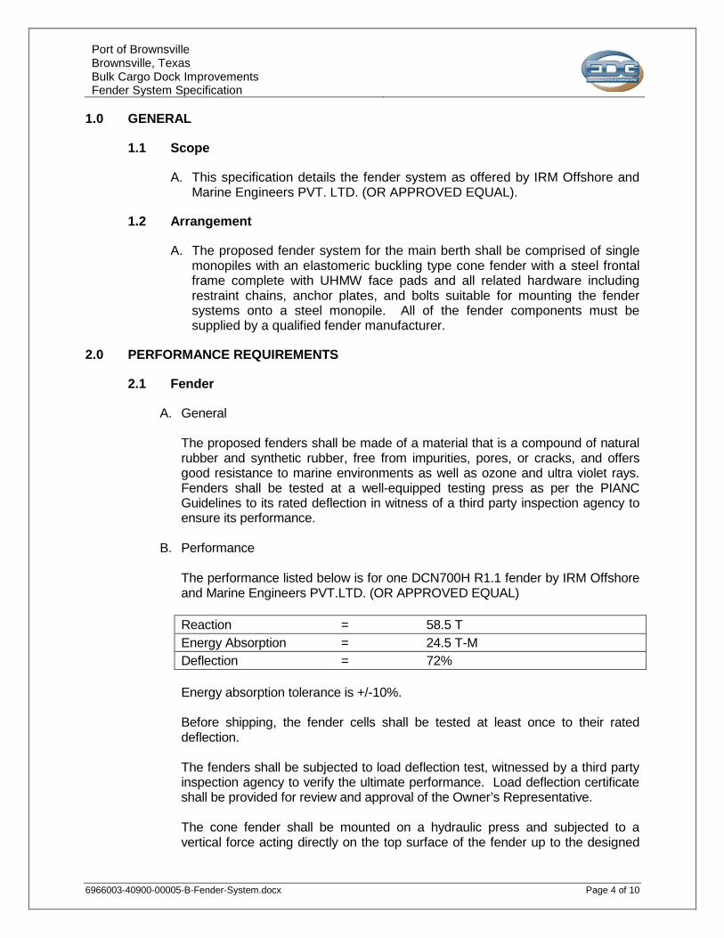
Port of Brownsville Brownsville, Texas Bulk Cargo Dock Improvements Fender System Specification
6966003-40900-00005-B-Fender-System.docx Page 4 of 10
1.0 GENERAL
1.1 Scope
A. This specification details the fender system as offered by IRM Offshore and Marine Engineers PVT. LTD. (OR APPROVED EQUAL).
1.2 Arrangement
A. The proposed fender system for the main berth shall be comprised of single monopiles with an elastomeric buckling type cone fender with a steel frontal frame complete with UHMW face pads and all related hardware including restraint chains, anchor plates, and bolts suitable for mounting the fender systems onto a steel monopile. All of the fender components must be supplied by a qualified fender manufacturer.
2.0 PERFORMANCE REQUIREMENTS
2.1 Fender
A. General The proposed fenders shall be made of a material that is a compound of natural rubber and synthetic rubber, free from impurities, pores, or cracks, and offers good resistance to marine environments as well as ozone and ultra violet rays. Fenders shall be tested at a well-equipped testing press as per the PIANC Guidelines to its rated deflection in witness of a third party inspection agency to ensure its performance.
B. Performance
The performance listed below is for one DCN700H R1.1 fender by IRM Offshore and Marine Engineers PVT.LTD. (OR APPROVED EQUAL) Reaction = 58.5 T Energy Absorption = 24.5 T-M Deflection = 72% Energy absorption tolerance is +/-10%. Before shipping, the fender cells shall be tested at least once to their rated deflection. The fenders shall be subjected to load deflection test, witnessed by a third party inspection agency to verify the ultimate performance. Load deflection certificate shall be provided for review and approval of the Owner’s Representative.
The cone fender shall be mounted on a hydraulic press and subjected to a vertical force acting directly on the top surface of the fender up to the designed
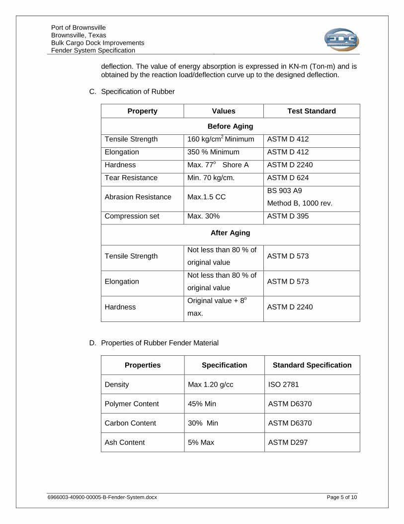
Port of Brownsville Brownsville, Texas Bulk Cargo Dock Improvements Fender System Specification
6966003-40900-00005-B-Fender-System.docx Page 5 of 10
deflection. The value of energy absorption is expressed in KN-m (Ton-m) and is obtained by the reaction load/deflection curve up to the designed deflection.
C. Specification of Rubber
Property Values Test Standard
Before Aging Tensile Strength 160 kg/cm2 Minimum ASTM D 412
Elongation 350 % Minimum ASTM D 412
Hardness Max. 77o Shore A ASTM D 2240
Tear Resistance Min. 70 kg/cm. ASTM D 624
Abrasion Resistance Max.1.5 CC BS 903 A9
Method B, 1000 rev.
Compression set Max. 30% ASTM D 395
After Aging
Tensile Strength Not less than 80 % of
original value ASTM D 573
Elongation Not less than 80 % of
original value ASTM D 573
Hardness Original value + 8o
max. ASTM D 2240
D. Properties of Rubber Fender Material
Properties Specification Standard Specification
Density Max 1.20 g/cc ISO 2781
Polymer Content 45% Min ASTM D6370
Carbon Content 30% Min ASTM D6370
Ash Content 5% Max ASTM D297
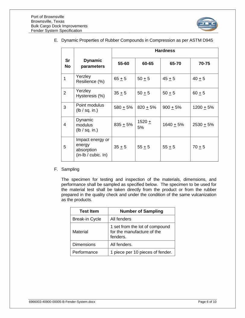
Port of Brownsville Brownsville, Texas Bulk Cargo Dock Improvements Fender System Specification
6966003-40900-00005-B-Fender-System.docx Page 6 of 10
E. Dynamic Properties of Rubber Compounds in Compression as per ASTM D945
Sr No
Dynamic parameters
Hardness
55-60 60-65 65-70 70-75
1 Yerzley Resilience (%) 65 + 5 50 + 5 45 + 5 40 + 5
2 Yerzley Hysteresis (%) 35 + 5 50 + 5 50 + 5 60 + 5
3 Point modulus (lb / sq. in.) 580 + 5% 820 + 5% 900 + 5% 1200 + 5%
4 Dynamic modulus (lb / sq. in.)
835 + 5% 1520 + 5% 1640 + 5% 2530 + 5%
5 Impact energy or energy absorption (in-lb / cubic. In)
35 + 5 55 + 5 55 + 5 70 + 5
F. Sampling
The specimen for testing and inspection of the materials, dimensions, and performance shall be sampled as specified below. The specimen to be used for the material test shall be taken directly from the product or from the rubber prepared in the quality check and under the condition of the same vulcanization as the products.
Test Item Number of Sampling Break-in Cycle All fenders
Material 1 set from the lot of compound for the manufacture of the fenders.
Dimensions All fenders.
Performance 1 piece per 10 pieces of fender.
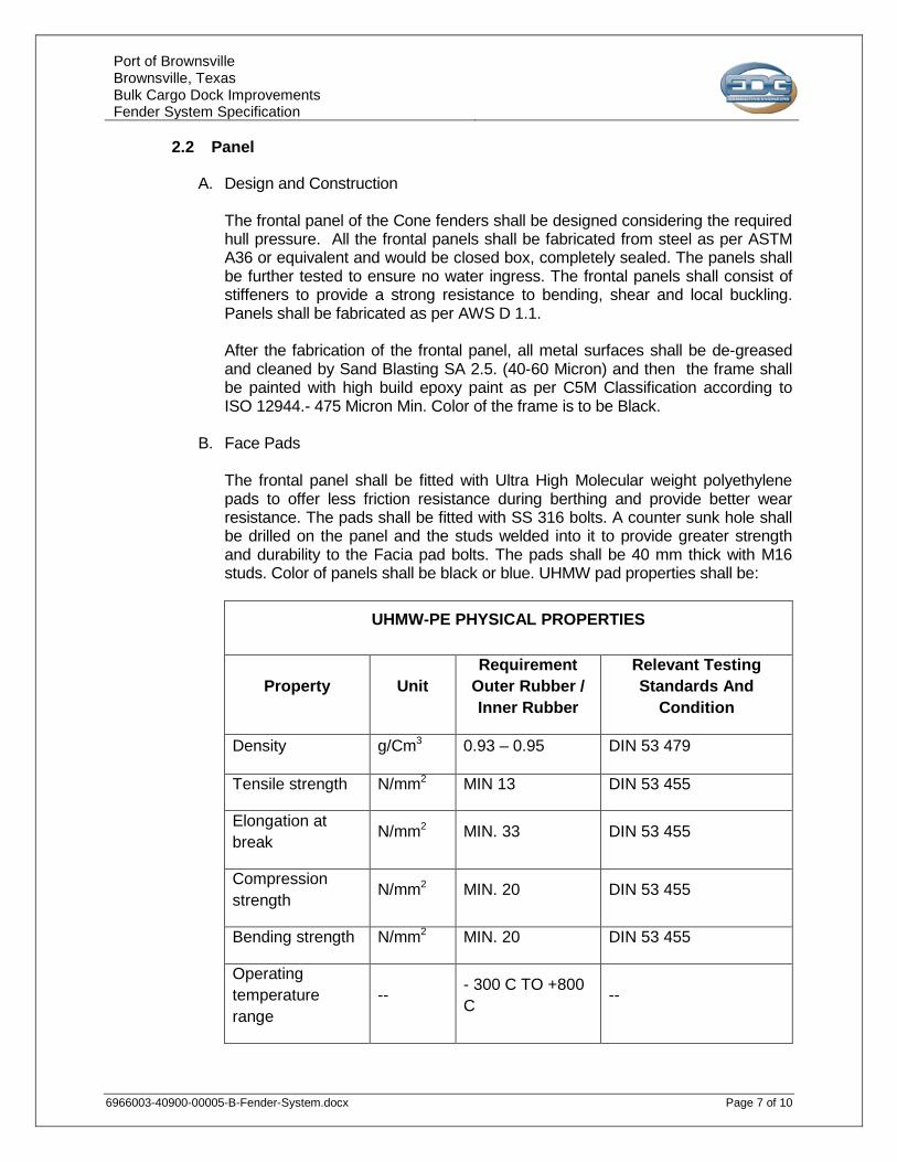
Port of Brownsville Brownsville, Texas Bulk Cargo Dock Improvements Fender System Specification
6966003-40900-00005-B-Fender-System.docx Page 7 of 10
2.2 Panel
A. Design and Construction The frontal panel of the Cone fenders shall be designed considering the required hull pressure. All the frontal panels shall be fabricated from steel as per ASTM A36 or equivalent and would be closed box, completely sealed. The panels shall be further tested to ensure no water ingress. The frontal panels shall consist of stiffeners to provide a strong resistance to bending, shear and local buckling. Panels shall be fabricated as per AWS D 1.1.
After the fabrication of the frontal panel, all metal surfaces shall be de-greased and cleaned by Sand Blasting SA 2.5. (40-60 Micron) and then the frame shall be painted with high build epoxy paint as per C5M Classification according to ISO 12944.- 475 Micron Min. Color of the frame is to be Black.
B. Face Pads The frontal panel shall be fitted with Ultra High Molecular weight polyethylene pads to offer less friction resistance during berthing and provide better wear resistance. The pads shall be fitted with SS 316 bolts. A counter sunk hole shall be drilled on the panel and the studs welded into it to provide greater strength and durability to the Facia pad bolts. The pads shall be 40 mm thick with M16 studs. Color of panels shall be black or blue. UHMW pad properties shall be:
UHMW-PE PHYSICAL PROPERTIES
Property Unit Requirement
Outer Rubber / Inner Rubber
Relevant Testing Standards And
Condition
Density g/Cm3 0.93 – 0.95 DIN 53 479
Tensile strength N/mm2 MIN 13 DIN 53 455
Elongation at break N/mm2 MIN. 33 DIN 53 455
Compression strength N/mm2 MIN. 20 DIN 53 455
Bending strength N/mm2 MIN. 20 DIN 53 455
Operating temperature range
-- - 300 C TO +800 C --
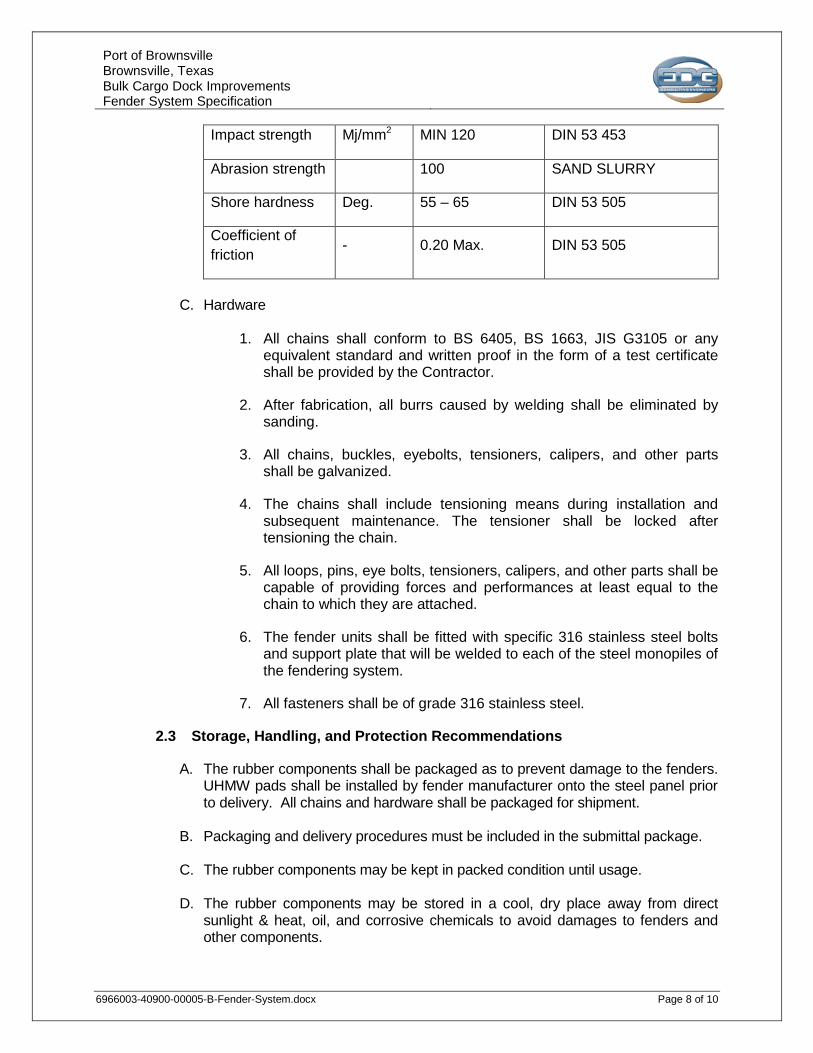
Port of Brownsville Brownsville, Texas Bulk Cargo Dock Improvements Fender System Specification
6966003-40900-00005-B-Fender-System.docx Page 8 of 10
Impact strength Mj/mm2 MIN 120 DIN 53 453
Abrasion strength 100 SAND SLURRY
Shore hardness Deg. 55 – 65 DIN 53 505
Coefficient of friction - 0.20 Max. DIN 53 505
C. Hardware
1. All chains shall conform to BS 6405, BS 1663, JIS G3105 or any
equivalent standard and written proof in the form of a test certificate shall be provided by the Contractor.
2. After fabrication, all burrs caused by welding shall be eliminated by sanding.
3. All chains, buckles, eyebolts, tensioners, calipers, and other parts shall be galvanized.
4. The chains shall include tensioning means during installation and subsequent maintenance. The tensioner shall be locked after tensioning the chain.
5. All loops, pins, eye bolts, tensioners, calipers, and other parts shall be capable of providing forces and performances at least equal to the chain to which they are attached.
6. The fender units shall be fitted with specific 316 stainless steel bolts and support plate that will be welded to each of the steel monopiles of the fendering system.
7. All fasteners shall be of grade 316 stainless steel.
2.3 Storage, Handling, and Protection Recommendations
A. The rubber components shall be packaged as to prevent damage to the fenders. UHMW pads shall be installed by fender manufacturer onto the steel panel prior to delivery. All chains and hardware shall be packaged for shipment.
B. Packaging and delivery procedures must be included in the submittal package.
C. The rubber components may be kept in packed condition until usage.
D. The rubber components may be stored in a cool, dry place away from direct sunlight & heat, oil, and corrosive chemicals to avoid damages to fenders and other components.
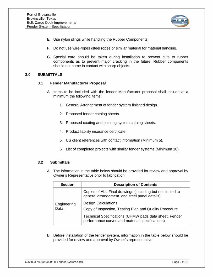
Port of Brownsville Brownsville, Texas Bulk Cargo Dock Improvements Fender System Specification
6966003-40900-00005-B-Fender-System.docx Page 9 of 10
E. Use nylon slings while handling the Rubber Components.
F. Do not use wire-ropes /steel ropes or similar material for material handling.
G. Special care should be taken during installation to prevent cuts to rubber
components as to prevent major cracking in the future. Rubber components should not come in contact with sharp objects.
3.0 SUBMITTALS
3.1 Fender Manufacturer Proposal
A. Items to be included with the fender Manufacturer proposal shall include at a minimum the following items:
1. General Arrangement of fender system finished design.
2. Proposed fender catalog sheets.
3. Proposed coating and painting system catalog sheets.
4. Product liability insurance certificate.
5. US client references with contact information (Minimum 5).
6. List of completed projects with similar fender systems (Minimum 10).
3.2 Submittals
A. The information in the table below should be provided for review and approval by Owner’s Representative prior to fabrication.
Section Description of Contents
Engineering Data
Copies of ALL Final drawings (including but not limited to general arrangement and steel panel details)
Design Calculations Copy of Inspection, Testing Plan and Quality Procedure
Technical Specifications (UHMW pads data sheet, Fender performance curves and material specifications)
B. Before installation of the fender system, information in the table below should be provided for review and approval by Owner’s representative.
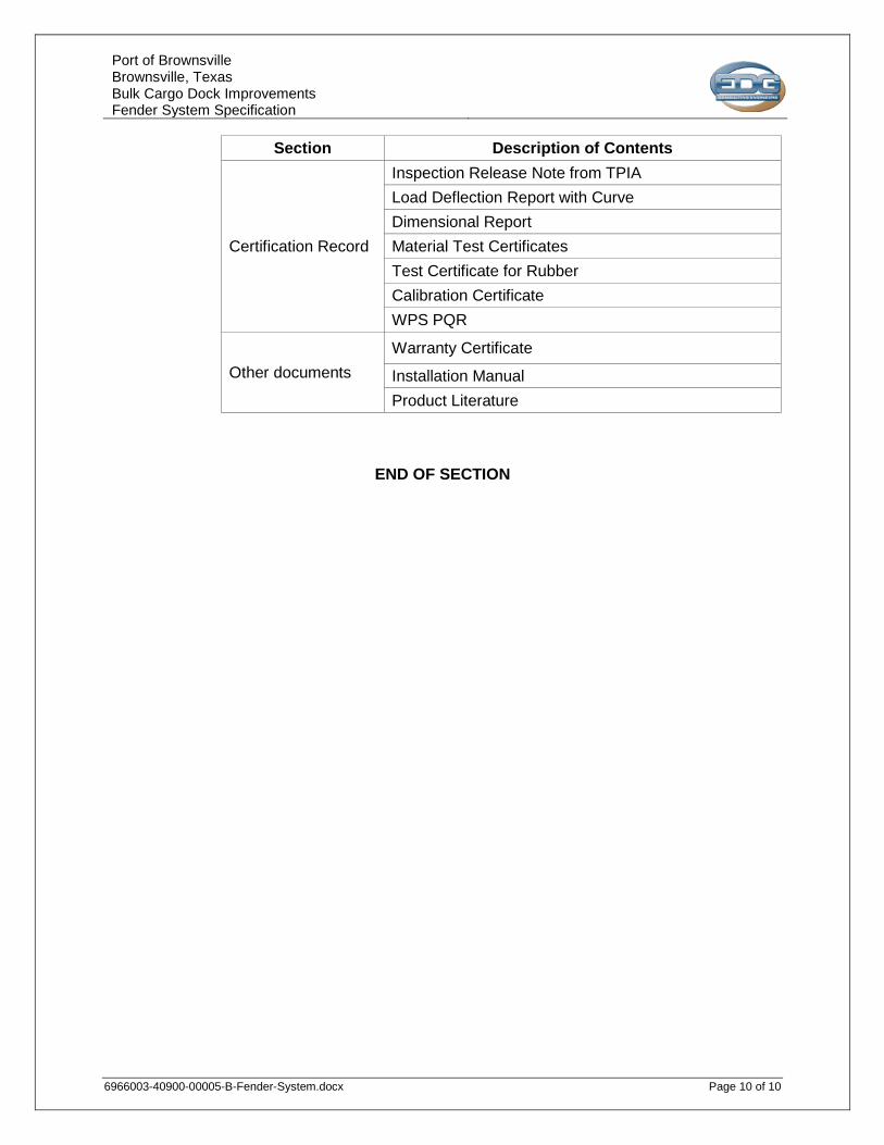
Port of Brownsville Brownsville, Texas Bulk Cargo Dock Improvements Fender System Specification
6966003-40900-00005-B-Fender-System.docx Page 10 of 10
Section Description of Contents
Certification Record
Inspection Release Note from TPIA Load Deflection Report with Curve Dimensional Report Material Test Certificates Test Certificate for Rubber Calibration Certificate WPS PQR
Other documents Warranty Certificate
Installation Manual Product Literature
END OF SECTION
BROWNSVILLE NAVIGATION DISTRICT
BULK CARGO DOCK IMPROVEMENTS
TIMBER PILES SPECIFICATION
Rev Description Date Prepared Reviewed Approved Client B Issued for Bid 05/07/2018 TMB MDP DRK
EDG Job No. 6966.003
EDG Document No. 6966003-40900-00006

Port of Brownsville Brownsville, Texas Bulk Cargo Dock Improvements Timber Piles Specification
6966003-40900-00006-B-TimberPiles.docx Page 2 of 8
Change Log
REV SECTION CHANGE DESCRIPTION
A - None – First Issuance B - Issued for Bid
Document Holds
REV SECTION CHANGE DESCRIPTION
A - None B - None
Port of Brownsville Brownsville, Texas Bulk Cargo Dock Improvements Timber Piles Specification
6966003-40900-00006-B-TimberPiles.docx Page 3 of 8
TABLE OF CONTENTS
1.0 GENERAL .......................................................................................................................4
1.1 Related Documents ................................................................................................... 4
1.2 Summary .................................................................................................................... 4
1.3 Action Submittals ...................................................................................................... 4
1.4 Information Submittals .............................................................................................. 4
1.5 Quality Assurance ..................................................................................................... 5
1.6 Delivery, Storage, and Handling ............................................................................... 5
1.7 Project Conditions ..................................................................................................... 5
2.0 GENERAL WORK DESCRIPTION .................................................................................5
2.1 Timber Piles ............................................................................................................... 5
2.2 Fabrication ................................................................................................................. 6
3.0 EXECUTION ...................................................................................................................6
3.1 Examination ............................................................................................................... 6
3.2 Driving Equipment ..................................................................................................... 6
3.3 Driving Piles ............................................................................................................... 6
3.4 Field Quality Control .................................................................................................. 8
3.5 Disposal ...................................................................................................................... 8
Port of Brownsville Brownsville, Texas Bulk Cargo Dock Improvements Timber Piles Specification
6966003-40900-00006-B-TimberPiles.docx Page 4 of 8
1.0 GENERAL
1.1 Related Documents
A. Drawings and general provisions of the Contract.
1.2 Summary
A. Specification includes round timber piles.
1.3 Action Submittals
A. Product Data: For each type of product indicated.
B. Shop Drawings: For timber piles. Show fabrication and installation details for piles, including details of driving shoes, tips or boots, and pile butt protection.
1.4 Information Submittals
A. Qualification Data: For qualified Installer.
B. Round timber pile treatment data as follows, including chemical treatment manufacturer's written instructions for handling, storing, installing, and finishing treated material:
1. For each type of preservative-treated timber product include certification by treating plant stating type of preservative solution and pressure process used, net amount of preservative retained, and compliance with applicable standards.
2. For waterborne-treated products include statement that moisture content of treated materials was reduced to levels indicated before shipment to Project site.
C. Pile-Driving Equipment Data: Include type, make, and rated energy range; weight of striking part of hammer; weight of drive cap; and, type, size, and properties of hammer cushion.
D. Static Pile Test Reports: Submit within three days of completing each test.
E. Pile-Driving Records: Submit within three days of driving each pile.
F. Field quality-control reports.
G. Warranty of chemical treatment manufacturer for each type of treatment.
H. Preconstruction Photographs: Photographs or video of existing conditions of adjacent construction. Submit before the Work begins.
Port of Brownsville Brownsville, Texas Bulk Cargo Dock Improvements Timber Piles Specification
6966003-40900-00006-B-TimberPiles.docx Page 5 of 8
1.5 Quality Assurance
A. Installer Qualifications: Manufacturer's authorized representative who is trained and approved for installation of units required for this Project.
1. Installer's responsibility includes engaging a qualified professional engineer to provide hammer design, testing, and prepare pile-driving records.
B. Testing Agency Qualifications: Qualified according to ASTM E 329 for testing indicated.
C. Pre-installation Conference: Conduct conference at Project site.
1.6 Delivery, Storage, and Handling
A. Deliver piles to Project site in such quantities and at such times to ensure continuity of installation. Handle and store piles at Project site to prevent breaks, cuts, abrasions, or other physical damage and as required by AWPA M4.
1. Do not drill holes or drive spikes or nails into pile below cutoff elevation, with exception of pile tension connectors.
1.7 Project Conditions
A. Protect structures, underground utilities, and other construction from damage caused by pile driving.
B. Site Information: A geotechnical report (Report by MEG Engineering) has been prepared for this Project and is referenced elsewhere in the Project Specifications for information only. For additional soil borings see General Notes on Contract Drawings.
C. Preconstruction Photographs: Inventory and record the condition of adjacent structures, underground utilities, and other construction. Provide photographs of conditions that might be misconstrued as damage caused by pile driving.
2.0 GENERAL WORK DESCRIPTION
2.1 Timber Piles
A. Round Timber Piles: ASTM D25, unused, clean peeled, one piece from butt to tip; of the following species and size basis:
1. Species: Southern yellow pine.
2. Size Basis: ASTM D25, minimum 12 inch butt, 9 inch tip.
Port of Brownsville Brownsville, Texas Bulk Cargo Dock Improvements Timber Piles Specification
6966003-40900-00006-B-TimberPiles.docx Page 6 of 8
B. Pressure-treat round timber piles according to AWPA C3 and AWPA C18 as follows:
3. Service Condition: Foundation.
4. Treatment: Treated to retain 0.80 CCA per AWPA C3.
2.2 Fabrication
A. Pile Butt: Trim pile butt and cut perpendicular to longitudinal axis of pile. Chamfer and shape butt to fit tightly to driving cap of hammer.
B. Field-Applied Wood Preservative: Treat field cuts, holes, and other penetrations according to AWPA M4.
1. Coal-tar roofing cement for treating drilled holes or sealing cutoffs
shall be free of asbestos.
C. Pile Splices: Splices will not be permitted.
D. Pile-Length Markings: Mark each pile with horizontal lines at 12-inch intervals; label the distance from pile tip at 60-inch intervals. Maintain markings on piles until driven.
3.0 EXECUTION
3.1 Examination
A. Site Conditions: Do not start pile-driving operations until earthwork fills have been completed or excavations have reached an elevation of 6 to 12 inches (152 to 305 mm) above bottom of footing or pile cap.
3.2 Driving Equipment
A. Pile Hammer: Air type capable of consistently delivering adequate peak-force duration and magnitude to develop the ultimate capacity required for type and size of pile driven and character of subsurface material anticipated.
B. Hammer Cushions and Driving Caps: Between hammer and top of pile, provide hammer cushion and steel driving cap as recommended by hammer manufacturer and as required to drive pile without damage.
C. Leads: Use fixed, semifixed, or hanging-type pile-driver leads that will hold full length of pile firmly in position and in axial alignment with hammer.
3.3 Driving Piles
A. General: Continuously drive piles to elevations or penetration resistance indicated on Contract Drawings. Establish and maintain axial alignment of leads and piles before and during driving.
Port of Brownsville Brownsville, Texas Bulk Cargo Dock Improvements Timber Piles Specification
6966003-40900-00006-B-TimberPiles.docx Page 7 of 8
B. Heaved Piles: Redrive heaved piles to tip elevation at least as deep as original tip elevation with a driving resistance at least as great as original driving resistance.
C. Driving Tolerances: Drive piles without exceeding the following tolerances, measured at pile heads:
1. Location: 3 inches (102 mm) from location indicated.
2. Plumb: Maintain 1 inch (25 mm) in 4 feet (1.2 m) from vertical, or a maximum of 4 inches (102 mm), measured when pile is aboveground in leads.
D. Withdraw damaged or defective piles and piles that exceed driving tolerances and install new piles within driving tolerances.
1. Fill holes left by withdrawn piles using cohesionless soil material such as gravel, broken stone, and gravel-sand mixtures. Place and compact in lifts not exceeding 72 inches (1.83 m).
2. Fill holes left by withdrawn piles as directed by Owner’s Representative.
E. Remove rejected piles and install new piles in locations as directed byOwner’s Representative.
F. Cutting Off: Cut off butts of driven piles square with pile axis and at elevations indicated.
1. Cover cut-off piling surfaces with minimum three coats of preservative treatment according to AWPA M4.
G. Pile-Driving Records: Maintain accurate driving records for each pile, compiled and attested to by a qualified professional engineer. Include the following data:
1. Project name and number.
2. Name of Contractor.
3. Pile species.
4. Pile location in pile group and designation of pile group.
5. Sequence of driving in pile group.
6. Pile dimensions.
7. Ground elevation.
Port of Brownsville Brownsville, Texas Bulk Cargo Dock Improvements Timber Piles Specification
6966003-40900-00006-B-TimberPiles.docx Page 8 of 8
8. Elevation of tips after driving.
9. Final tip and cutoff elevations of piles after driving pile group.
10. Records of redriving.
11. Type, make, model, and rated energy of hammer.
12. Weight and stroke of hammer.
13. Type of pile-driving cap used.
14. Cushion material and thickness.
15. Actual stroke and blow rate of hammer.
16. Pile-driving start and finish times, and total driving time.
17. Time, pile-tip elevation, and reason for interruptions.
18. Number of blows for every 12 inches (305 mm) of penetration, and number of blows per 1 inch (25 mm) for the last 6 inches (152 mm) of driving.
19. Pile deviations from location and plumb.
20. Pre-boring, jetting, or special procedures used.
21. Unusual occurrences during pile driving.
3.4 Field Quality Control
A. Testing Agency: General Contractor will engage a qualified independent testing agency to perform tests and inspections.
B. Tests and Inspections:
Dynamic Pile Testing: High-strain dynamic monitoring shall be performed and reported according to ASTM D 4945 during initial driving and during restriking on one pile from the two westernmost mooring bollard foundations and one pile from the eastern most mooring bollard foundation.
3.5 Disposal
A. Remove withdrawn piles and cutoff sections of piles from site and legally dispose of them off Owner's property.
END OF SECTION