Embed Size (px)
Citation preview
Loughborough UniversityInstitutional Repository
Structure from motion(SFM) photogrammetry
This item was submitted to Loughborough University's Institutional Repositoryby the/an author.
Citation: MICHELETTI, N., CHANDLER, J.H. and LANE, S.N., 2015. Struc-ture from motion (SFM) photogrammetry. IN: Clarke, L.E. and Nield, J.M.(Eds.) Geomorphological Techniques (Online Edition). London: British Soci-ety for Geomorphology. ISSN: 2047-0371, Chap. 2, Sec. 2.2.
Additional Information:
• This is an edited book chapter in Geomorphological Techniques(Online Edition) (ISSN 2047-0371). It is also available at:http://www.geomorphology.org.uk/sites/default/files/geom_tech_chapters/2.2.2_sfm.pdf
Metadata Record: https://dspace.lboro.ac.uk/2134/17493
Version: Published
Publisher: British Society for Geomorphology
Rights: This work is made available according to the conditions of the Cre-ative Commons Attribution-NonCommercial-NoDerivatives 4.0 International(CC BY-NC-ND 4.0) licence. Full details of this licence are available at:https://creativecommons.org/licenses/by-nc-nd/4.0/
Please cite the published version.
British Society for Geomorphology Geomorphological Techniques, Chap. 2, Sec. 2.2 (2015)
Structure from Motion (SfM) Photogrammetry Natan Micheletti1 , Jim H Chandler2 , Stuart N Lane1 1 Institute of Earth Surface Dynamics, University of Lausanne ([email protected]) 2 School of Civil and Building Engineering, Loughborough University
ABSTRACT: Topographic data measurement is a fundamental aspect of many geomorphic research applications, particularly those including landform monitoring and investigation of changes in topography. However, most surveying techniques require relatively expensive technologies or specialized user supervision. Structure from Motion (SfM) photogrammetric technology reduces both these constraints by allowing the use of consumer grade digital cameras and highly automated data processing, which can be free to use. SfM photogrammetry therefore offers the possibility of fast, automated and low-cost acquisition of 3-D data, which has inevitably created great interest amongst the geomorphological community. In this contribution, the basic concepts of SfM photogrammetry are presented, whilst recognising its heritage. A few examples are employed to illustrate the potential of SfM applications for geomorphological research. In particular, SfM photogrammetry offers to geomorphologists a tool for high-resolution characterisation of 3-D forms at a range of scales and for change detection purposes. The high level of automation of SfM data processing creates both opportunities and threats, particularly because user control tends to focus upon visualisation of the final product rather than upon inherent data quality. Accordingly, this contribution seeks to guide potential new users in successfully applying SfM for a range of geomorphic studies. KEYWORDS: Structure from Motion, close-range photogrammetry, smartphone technology, surveying systems, surface morphology
Introduction Geomorphological approaches for the acquisition of topographic data are experiencing a remarkable technological leap nowadays, with both a substantial increase in the possible frequency of three-dimensional terrain surveying and the ease in which associated methods can be applied. Traditionally, topographic research focused upon constructing digital elevation models (DEMs) using photogrammetric (e.g. Lane et al., 1994; Barker et al., 1997; Chandler, 1999; Lane, 2000; Westaway et al., 2000; Bennett et al., 2012) and differential global positioning system (dGPS) (e.g. Fix and Burt, 1995; Brasington et al., 2000; Young, 2012) data. More recently, both airborne and terrestrial laser scanner have been widely employed to collect very high-quality and high resolution data (Heritage and Hetherington, 2007; Alho et al., 2009; Hodge et al., 2009a, 2009b;
Schaefer and Inkpen, 2010). However, most of these techniques still require expensive equipment and specialized user expertise to process data and improve its quality. In contrast, the development of Structure from Motion (SfM) methods provides the opportunity for very low-cost three-dimensional data acquisition with strongly reduced user supervision and required expertise. The ability to extract high resolution and accurate spatial data using cheap consumer grade digital cameras appears truly remarkable and SfM photogrammetry could answer a range of new research questions. As in traditional photogrammetry, SfM photogrammetry employs overlapping images acquired from multiple viewpoints. However, SfM photogrammetry differs from traditional photogrammetric approaches by determining internal camera geometry and camera
ISSN 2047-0371
Structure from Motion 2
British Society for Geomorphology Geomorphological Techniques, Chap. 2, Sec. 2.2 (2015)
position and orientation automatically and without the need for a pre-defined set of “ground control”, visible points at known three-dimensional positions (Westoby et al., 2012). The need for a high degree of overlap to cover the full geometry of the object or scene of interest, gives rise to the name: structure derived from a moving sensor. Whilst the exact implementation of SfM may vary with how it is coded, the general approach has been outlined by other authors (Westoby et al., 2012; James and Robson, 2012; Fonstad et al., 2013; Micheletti et al., 2014) and only a brief explanation is required here. In essence, multiple views of an object are captured with a digital camera from a range of different positions. A scale invariant feature transform (SIFT) then identifies common feature points across the image set, sufficient to establish the spatial relationships between the original image locations in an arbitrary 3-D coordinate system. A sparse bundle adjustment (e.g. Snavely et al., 2008), needed to transform measured image co-ordinates into 3-D points covering the area of interest, is used in this process. The result is three-dimensional locations of the feature points in the form of a sparse point cloud in the same local 3-D co-ordinate system. Accurate key point correspondence requires the availability of visually distinct texture appearing in the imagery, which can present a problem with some objects and/or lighting conditions. The sparse point cloud is then intensified using Multi View Stereo (MVS) techniques (e.g. Furukawa and Ponce, 2010; Rothermel et al., 2012). It is the ability of these techniques to generate very high resolution datasets, whilst isolating and removing gross errors, which is now allowing such visually impressive 3-D models to be generated so easily when compared to traditional stereo based DEM generation methods involving “stereomatching” (Remondino et al., 2014). Effectively, because of the ease with which sensor distortion can be modelled, all consumer grade digital cameras, including the ubiquitous “smartphone”, can acquire valuable geomorphic data (Micheletti et al., 2014). Furthermore, the recent development of low-cost, sometimes free, internet-based processing systems enable the upload, processing and download of the derived 3-D data in just a few minutes, potentially during field data collection. This is in direct contrast
to traditional photogrammetric software, where the user is forced to define and to determine interior and exterior orientation parameters explicitly. Most SfM platforms are now fully automated. The advantage of SfM is that it provides a black-box tool where expert supervision is unnecessary. It may also be a disadvantage in that the user has much less involvement in data quality control and the origins of error in data may not be identifiable. This paper presents guidelines and a workflow for the application of SfM photogrammetry with a hand-held camera, to help avoid generating such inaccurate datasets. Examples and considerations are taken from a study conducted by Micheletti et al. (2014) involving ground-based imagery. Although not discussed formally here, all principles also remain valid for images obtained using other approaches such as with Unmanned Aerial Vehicles (UAVs) or drones.
Photogrammetric heritage The term Structure-from-Motion has evolved from the machine vision community, specifically for tracking points across sequences of images occupied from different positions (e.g. Spetsakis and Aloimonos, 1999; Boufama et al., 1993; Szeliski and Kang, 1994). SfM owes its existence to innovations and mathematical models developed many generations ago, particularly in photogrammetry. The coplanarity condition, now used to establish the spatial relationship between images, was applied in the 1950 and 1960s for numerical aerial triangulation and mapping from aerial photography (Thompson, 1965). The bundle adjustment, which implements the collinearity condition to establish a mathematically rigorous relationship between image and object, was established later by Brown (1971, 1976), Kenefick et al. (1972) and Granshaw (1980). Only perfect metric cameras generate images which are distortion free. However, a “self-calibrating” bundle adjustment (Kenefick et al., 1972; Faig and Moniwa, 1973) can model and estimate additional parameters suitable to represent a wide range of internal distortions associated with consumer grade digital cameras. Unfortunately, much of this important pioneering work necessary to establish both appropriate camera models
3 Natan Micheletti et al.
British Society for Geomorphology Geomorphological Techniques, Chap. 2, Sec. 2.2 (2015)
(e.g. Patias and Streilein, 1996; Shortis et al., 1998) and appropriate geometry necessary for their accurate recovery (Fraser, 1984; Wester-Ebbinghaus, 1986), and the lessons that come from this work, is often overlooked. The freely available and fully automated software packages are flexible and do not assume that the same camera has been used to acquire all images. Each frame may therefore be calibrated individually and inappropriate geometry/image overlaps can generate inaccurate camera models and hence inaccurate datasets.
Method Software There are a range of SfM tools now available. PC software, smartphone and web-based apps usually provide similar services for 3-D model generation but differ in the range of post-processing options. Nevertheless, a distinction can be made between solutions that upload images to companies’ servers to be processed and provide a download of the results afterwards (e.g. Autodesk 123D Catch, www.123dapp.com/catch or Microsoft Photosynth, www.photosynth.net) and tools that actually process the data on the local machine (e.g. Agisoft PhotoScan, www-agisoft.com, or VisualSFM developed by Wu, 2013, ccwum.me/vsfm). Most tools are available freely, but recently SfM algorithms have been implemented in more conventional and commercial close-range photogrammetry software requiring a subscription (e.g. PhotoModeler release 2014). Whilst, most offer the possibility to download or extract 3-D outputs, some online services still act primarly as web-based 3-D visualization platforms. SfM services vary in their characteristics and options. Some software resamples images to speed up computations (e.g. Autodesk 123D Catch, currently reduces image resolution to 3 Mega Pixels). Thus, a high-resolution sensor is not usually required but this may limit the precision of generated data. It necessitates careful consideration of the distance between the sensor and the zone of interest, to maintain required resolution. The availability of data used to describe the camera geometry also varies, limiting objective assessment of internal geometry. In contrast, the output is commonly easy to use,
generally 3-D meshes with a basic control upon their density. Point clouds (the nodes of the meshes) can normally be exported in LAS or ASCII format files, allowing further analysis or use in other software.
Data acquisition SfM involves a process that automatically finds and matches a limited number of common features between images which are then used to establish both interior and exterior orientation parameters. A subsequent procedure then extracts a high resolution and colour-coded point cloud to represent the object. For this reason, the acquisition of imagery with the right characteristics is critical. A range of cameras can be used but a digital SLR camera equipped with fixed focus lens will generate the most accurate data as widely varying zoom settings can cause difficulties (Shortis et al., 2006, Sanz-Ablanedo et al., 2012). Images do not need to be acquired from the same distance or have the same scale (see Figure 1). On the contrary, it is advisable to acquire multi-scale image sets which initially capture the whole site with a few frames before obtaining closer range images to capture the desired detail at the required precision. This is particularly important when capturing areas of detail which are physically obscured by other features (i.e. occlusions). The whole set of images is used for feature extraction, so it is fundamental to ensure that the scene is static and that exposures capture the detail required. Flash photography frequently creates inconsistent image textures which can confuse the feature-matching process (Micheletti et al., 2014). The spatial relationship between images is more flexible than traditional photogrammetric image acquisition using stereo-pairs (Chandler, 1999, Remondino et al., 2014). However, it is critical to acquire imagery from as many different spatial positions as possible. The wide range of image directions then creates a dataset with a strong geometry, important to recover both internal camera models and precise, and hence accurate, object coordinates. The exact number of photographs required is dictated on a case-by-case basis and is a function of occlusion, shape complexity and scale. A range between 10 and 100 should be a good starting point for most applications at close (cm to 10s of m) and intermediate (<
Structure from Motion 4
British Society for Geomorphology Geomorphological Techniques, Chap. 2, Sec. 2.2 (2015)
1km) scales. Micheletti et al. (2014) demonstrated that increasing the number of images produces denser meshes and improves model accuracy. More significantly, this investigation showed how larger datasets help to remove outliers when the number of images is already sufficient for a good representation of the surface of interest. Hence, very large datasets are not always necessary as even small image sets are able to provide outputs of very satisfying quality, provided image geometry remains strong throughout the area of interest. An important practical constraint is computer memory and the associated time users are willing to wait for results. Transparent, reflective or homogeneous surfaces present difficulties because incorrect features can be linked during the automatic feature-matching process (Autodesk, 2014). Finally, and of importance to many geomorphic studies, the post-registration procedures combined with a clear idea of what these quantitative data are to be used for, must be planned in advance (see detailed section below).
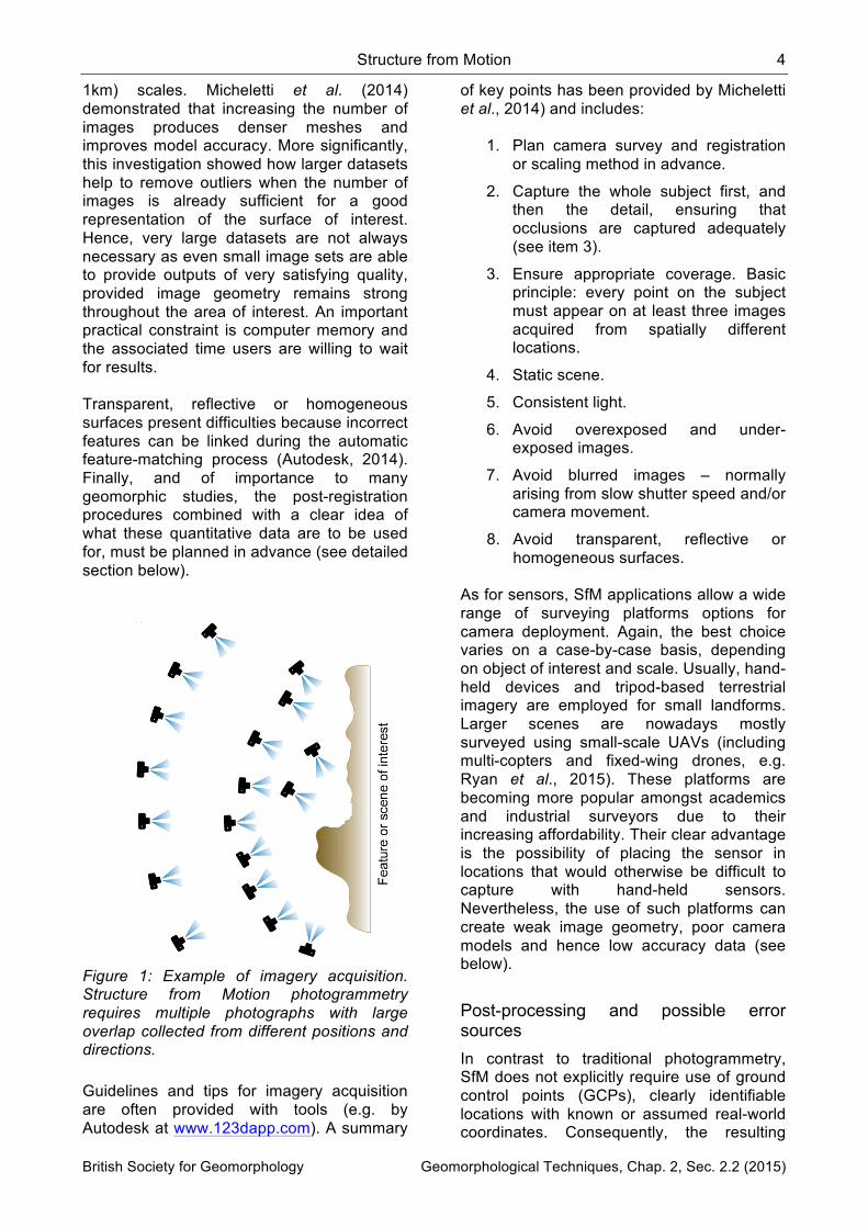
Figure 1: Example of imagery acquisition. Structure from Motion photogrammetry requires multiple photographs with large overlap collected from different positions and directions. Guidelines and tips for imagery acquisition are often provided with tools (e.g. by Autodesk at www.123dapp.com). A summary
of key points has been provided by Micheletti et al., 2014) and includes:
1. Plan camera survey and registration or scaling method in advance.
2. Capture the whole subject first, and then the detail, ensuring that occlusions are captured adequately (see item 3).
3. Ensure appropriate coverage. Basic principle: every point on the subject must appear on at least three images acquired from spatially different locations.
4. Static scene.
5. Consistent light.
6. Avoid overexposed and under-exposed images.
7. Avoid blurred images – normally arising from slow shutter speed and/or camera movement.
8. Avoid transparent, reflective or homogeneous surfaces.
As for sensors, SfM applications allow a wide range of surveying platforms options for camera deployment. Again, the best choice varies on a case-by-case basis, depending on object of interest and scale. Usually, hand-held devices and tripod-based terrestrial imagery are employed for small landforms. Larger scenes are nowadays mostly surveyed using small-scale UAVs (including multi-copters and fixed-wing drones, e.g. Ryan et al., 2015). These platforms are becoming more popular amongst academics and industrial surveyors due to their increasing affordability. Their clear advantage is the possibility of placing the sensor in locations that would otherwise be difficult to capture with hand-held sensors. Nevertheless, the use of such platforms can create weak image geometry, poor camera models and hence low accuracy data (see below).
Post-processing and possible error sources In contrast to traditional photogrammetry, SfM does not explicitly require use of ground control points (GCPs), clearly identifiable locations with known or assumed real-world coordinates. Consequently, the resulting
5 Natan Micheletti et al.
British Society for Geomorphology Geomorphological Techniques, Chap. 2, Sec. 2.2 (2015)
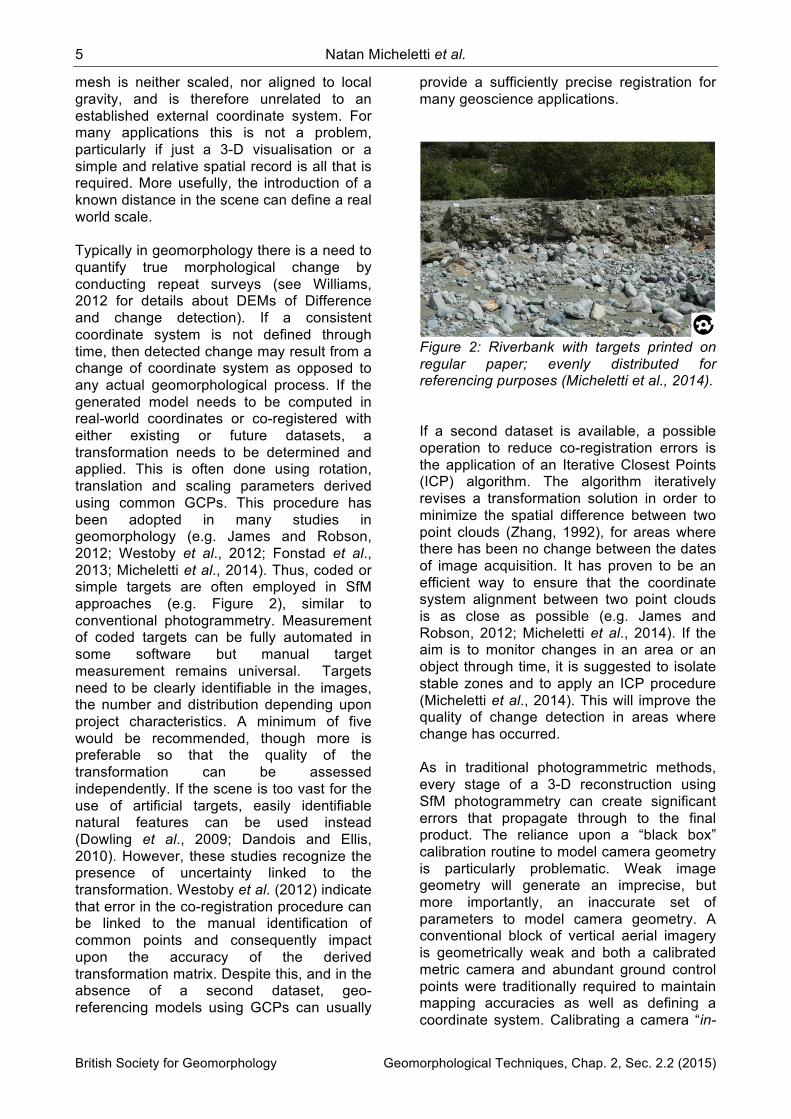
mesh is neither scaled, nor aligned to local gravity, and is therefore unrelated to an established external coordinate system. For many applications this is not a problem, particularly if just a 3-D visualisation or a simple and relative spatial record is all that is required. More usefully, the introduction of a known distance in the scene can define a real world scale. Typically in geomorphology there is a need to quantify true morphological change by conducting repeat surveys (see Williams, 2012 for details about DEMs of Difference and change detection). If a consistent coordinate system is not defined through time, then detected change may result from a change of coordinate system as opposed to any actual geomorphological process. If the generated model needs to be computed in real-world coordinates or co-registered with either existing or future datasets, a transformation needs to be determined and applied. This is often done using rotation, translation and scaling parameters derived using common GCPs. This procedure has been adopted in many studies in geomorphology (e.g. James and Robson, 2012; Westoby et al., 2012; Fonstad et al., 2013; Micheletti et al., 2014). Thus, coded or simple targets are often employed in SfM approaches (e.g. Figure 2), similar to conventional photogrammetry. Measurement of coded targets can be fully automated in some software but manual target measurement remains universal. Targets need to be clearly identifiable in the images, the number and distribution depending upon project characteristics. A minimum of five would be recommended, though more is preferable so that the quality of the transformation can be assessed independently. If the scene is too vast for the use of artificial targets, easily identifiable natural features can be used instead (Dowling et al., 2009; Dandois and Ellis, 2010). However, these studies recognize the presence of uncertainty linked to the transformation. Westoby et al. (2012) indicate that error in the co-registration procedure can be linked to the manual identification of common points and consequently impact upon the accuracy of the derived transformation matrix. Despite this, and in the absence of a second dataset, geo-referencing models using GCPs can usually
provide a sufficiently precise registration for many geoscience applications.
Figure 2: Riverbank with targets printed on regular paper; evenly distributed for referencing purposes (Micheletti et al., 2014). If a second dataset is available, a possible operation to reduce co-registration errors is the application of an Iterative Closest Points (ICP) algorithm. The algorithm iteratively revises a transformation solution in order to minimize the spatial difference between two point clouds (Zhang, 1992), for areas where there has been no change between the dates of image acquisition. It has proven to be an efficient way to ensure that the coordinate system alignment between two point clouds is as close as possible (e.g. James and Robson, 2012; Micheletti et al., 2014). If the aim is to monitor changes in an area or an object through time, it is suggested to isolate stable zones and to apply an ICP procedure (Micheletti et al., 2014). This will improve the quality of change detection in areas where change has occurred. As in traditional photogrammetric methods, every stage of a 3-D reconstruction using SfM photogrammetry can create significant errors that propagate through to the final product. The reliance upon a “black box” calibration routine to model camera geometry is particularly problematic. Weak image geometry will generate an imprecise, but more importantly, an inaccurate set of parameters to model camera geometry. A conventional block of vertical aerial imagery is geometrically weak and both a calibrated metric camera and abundant ground control points were traditionally required to maintain mapping accuracies as well as defining a coordinate system. Calibrating a camera “in-
Structure from Motion 6
British Society for Geomorphology Geomorphological Techniques, Chap. 2, Sec. 2.2 (2015)
situ” using a conventional block of vertical imagery acquired using a UAV is likely to generate inaccurate data. This typically manifests itself in the form of a systematic error surface or “dome” caused by an inaccurate lens model (Wackrow and Chandler, 2008; James and Robson, 2014) which can often be overlooked (e.g. Ouédraogo et al., 2014). One simple recommendation is to strengthen image geometry by obtaining oblique imagery in addition to the vertical dataset acquired for object coverage. This requires particularly careful attention to be given to the design of UAV surveys. Together, imagery acquisition and output registration remain delicate steps in otherwise highly automated SfM photogrammetry. For this reason, it is important to consider a priori the best strategy whilst considering the specific geoscience application and accuracies that are realistic.
Useful tools and alternatives Commonly, freely available SfM packages have very limited post-processing functions. As a result, it is often necessary to rely on other software for registration or quantitative analyses. Since many packages offer the possibility to export mesh nodes in LAS or ASCII format files, it is not difficult to find appropriate software to read the data and, if needed, interpolate it to facilitate its use. If working on point clouds is desired, the point cloud data management software CloudCompare developed by EDF R&D (http://progress.edf.com) is a convenient solution in terms of both cost and performance (the software is freely available at www.danielgm.net/cc). CloudCompare provides basic manual registration tools, an application of the ICP algorithm and also a point cloud – point cloud comparison tool in the form of the chamfer matching algorithm (Barrow et al., 1977). The chamfer matching algorithm returns values of dissimilarity between two datasets in the form of three-dimensional distances computed by associating each point in the compared dataset with its closest point in the reference
data. Furthermore, CloudCompare now supports the M3C2 cloud-to-cloud differencing algorithm (Brodu and Lague, 2012) as well, an alternative to the original cloud-to-cloud approach. Despite being more computationally demanding than elevation differencing of rasterized DEMs, cloud-to-cloud approaches remain a flexible alternative to comparing more complex 3-D datasets. For point cloud registration, the transformation applied by Westoby et al. (2012) and Micheletti et al. (2014) uses a Matlab implementation of the Horn’s absolute orientation algorithm (Horn, 1987) called ABSOR (Jacobson, 2009). Finally, Table 1 summarises the technical aspects of a range of hand-held sensors used to acquire high resolution topographic data.
Examples An investigation on the quality of SfM applications for close-range measurement and intermediate measurement scales is presented in Micheletti et al. (2014). The freely available, internet-based SfM service offered by Autodesk 123D Catch (www.123dapp.com/catch) was used in conjunction with imagery collected with both a smartphone (Apple iPhone 4) and a digital single-lens reflex camera (Nikon D7000). Extracted models were compared with PhotoModeler implementing traditional stereo based model extraction, whilst using terrestrial laser scanner (TLS) data as a benchmark. Close-range measurement scale For a close-range measurement study, the riverbank used (Figure 2) was 10 m long by 1.20 m high and characterized by heterogeneous texture, with grains of different sizes in a coarse-sand and gravel matrix. Using only 13 photographs it was possible to create automatically a three-dimensional point cloud using 123D Catch (Figure 3).

7 Natan Micheletti et al.
British Society for Geomorphology Geomorphological Techniques, Chap. 2, Sec. 2.2 (2015)
Table 1: Technical aspects and some possible alternatives for the acquisition of high resolution topographic data in terrain surveys (Micheletti et al., 2014). See also Young (2012).
Technical aspect Options Main characteristics
Survey Smartphone Low cost, portable wireless internet access, low quality
Consumer-grade digital sensor Low cost, moderate quality
High-quality digital SLR sensor High quality, portable, moderate cost, no internet access
Laser Scanning (TLS and ALS) High precision, expensive, less portable
Image processing
Internet-based SfM Free, near real time, fully automatic, lower quality
Local software SfM Mostly free and automatic, better quality expected
Traditional « stereo » photogrammetry
High quality, subscription cost, expert knowledge
SfM-MVS photogrammetry As above, but also greater automation and reliability
Co-registration Scaling Fast and easy, comparison with other datasets not possible
Tie points Comparison with other datasets only, average precision
Targets + GCP Any coordinate system, high precision, not always possible
ICP Refinement of alignment, needs two co-registered datasets
Figure 3: Image-covered mesh (above) and its wireframe (below) generated using smartphone imagery and 123D Catch (Micheletti et al., 2014). Photogrammetric targets were used to transform the point cloud for comparison purposes using the methodology described
earlier. The comparison was performed in Cloud Compare using TLS data as a benchmark. Median error was 0.0044 and 0.0148 meters for the Nikon D7000 and for the smartphone imagery respectively. These values reduced to 0.0034 and 0.0079 meters after ICP application, proving how registration errors can play a critical role. Despite the downscaling applied to the images prior to data processing, the Nikon D7000 imagery provided optimum results. However, the advantage of a smartphone, in addition to cost, is the possibility of previewing output in the field using wireless communication systems. In any case, sub-centimetre precision could be achieved using SfM photogrammetry for close-range studies, if appropriate care is used during the co-registration procedure. In the low light conditions prevalent in higher latitudes during the winter, tripod-based
Structure from Motion 8
British Society for Geomorphology Geomorphological Techniques, Chap. 2, Sec. 2.2 (2015)
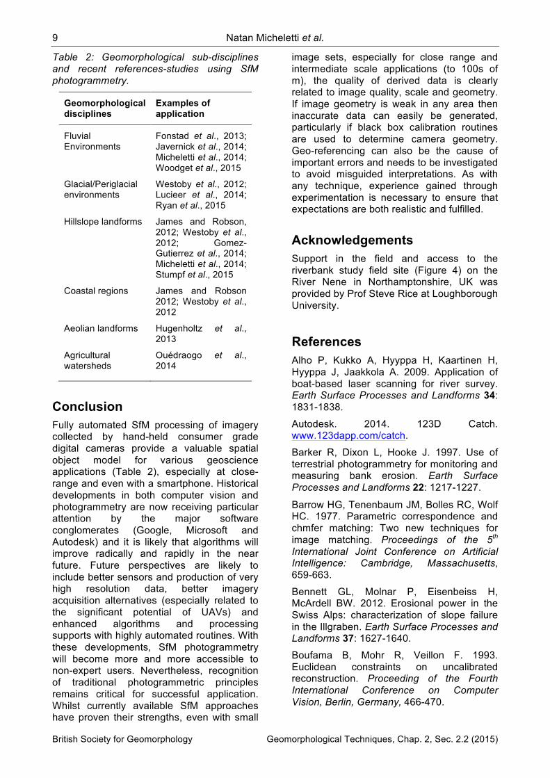
terrestrial imagery can be valuable. A Nikon D7000 digital SLR camera was used to acquire 25 images from a range of distances, necessary to capture a 6 m section of another evolving riverbank in Northamptonshire, UK, on a cloudy day in November. A ground control network was established using a Trimble Total Station, suitable for longer term monitoring and registration purposes. Imagery has been processed using the internet-based, freely available 123D Catch support, but also with the commercial PhotoModeler-SfM/MVS software to perform a comparison (Figure 4). Although the number of points extracted differed (c. 1,9 million for PhotoModeler versus 255,045 for 123D Catch), results demonstrate the high accuracy of the free software. A cloud-to-cloud comparison between the two highlighted just minor differences, median error being 0.004 m for the non-vegetated area.
Figure 4: Data extracted using tripod-based terrestrial Nikon D7000 imagery with PhotoModeler SfM/MVS (above) and 123D Catch (below). Targets for registration purposes are distributed throughout the area of interest.
Intermediate measurement scale An alluvial fan of approximately 87,000 m2
was chosen to represent an intermediate case study. A number of complications characterise this experiment, particularly the size of the object and the receding oblique viewpoint from the valley-based imagery. Accordingly, features on the fan are not all captured at the ideal angles/levels of texture. Further, since the object was too large to use photogrammetric targets easily, well-defined
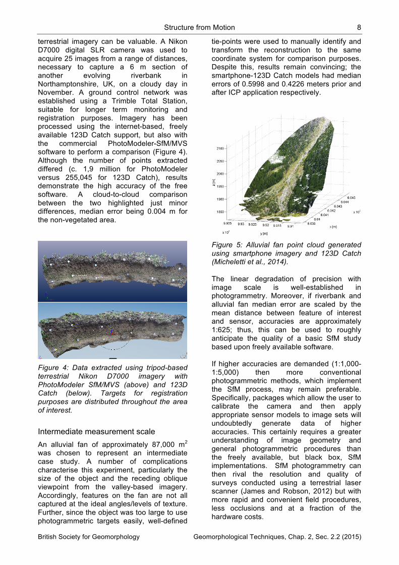
tie-points were used to manually identify and transform the reconstruction to the same coordinate system for comparison purposes. Despite this, results remain convincing; the smartphone-123D Catch models had median errors of 0.5998 and 0.4226 meters prior and after ICP application respectively.
Figure 5: Alluvial fan point cloud generated using smartphone imagery and 123D Catch (Micheletti et al., 2014). The linear degradation of precision with image scale is well-established in photogrammetry. Moreover, if riverbank and alluvial fan median error are scaled by the mean distance between feature of interest and sensor, accuracies are approximately 1:625; thus, this can be used to roughly anticipate the quality of a basic SfM study based upon freely available software. If higher accuracies are demanded (1:1,000-1:5,000) then more conventional photogrammetric methods, which implement the SfM process, may remain preferable. Specifically, packages which allow the user to calibrate the camera and then apply appropriate sensor models to image sets will undoubtedly generate data of higher accuracies. This certainly requires a greater understanding of image geometry and general photogrammetric procedures than the freely available, but black box, SfM implementations. SfM photogrammetry can then rival the resolution and quality of surveys conducted using a terrestrial laser scanner (James and Robson, 2012) but with more rapid and convenient field procedures, less occlusions and at a fraction of the hardware costs.
9 Natan Micheletti et al.
British Society for Geomorphology Geomorphological Techniques, Chap. 2, Sec. 2.2 (2015)
Table 2: Geomorphological sub-disciplines and recent references-studies using SfM photogrammetry.
Geomorphological disciplines
Examples of application
Fluvial Environments
Fonstad et al., 2013; Javernick et al., 2014; Micheletti et al., 2014; Woodget et al., 2015
Glacial/Periglacial environments
Westoby et al., 2012; Lucieer et al., 2014; Ryan et al., 2015
Hillslope landforms James and Robson, 2012; Westoby et al., 2012; Gomez-Gutierrez et al., 2014; Micheletti et al., 2014; Stumpf et al., 2015
Coastal regions James and Robson 2012; Westoby et al., 2012
Aeolian landforms Hugenholtz et al., 2013
Agricultural watersheds
Ouédraogo et al., 2014
Conclusion Fully automated SfM processing of imagery collected by hand-held consumer grade digital cameras provide a valuable spatial object model for various geoscience applications (Table 2), especially at close-range and even with a smartphone. Historical developments in both computer vision and photogrammetry are now receiving particular attention by the major software conglomerates (Google, Microsoft and Autodesk) and it is likely that algorithms will improve radically and rapidly in the near future. Future perspectives are likely to include better sensors and production of very high resolution data, better imagery acquisition alternatives (especially related to the significant potential of UAVs) and enhanced algorithms and processing supports with highly automated routines. With these developments, SfM photogrammetry will become more and more accessible to non-expert users. Nevertheless, recognition of traditional photogrammetric principles remains critical for successful application. Whilst currently available SfM approaches have proven their strengths, even with small
image sets, especially for close range and intermediate scale applications (to 100s of m), the quality of derived data is clearly related to image quality, scale and geometry. If image geometry is weak in any area then inaccurate data can easily be generated, particularly if black box calibration routines are used to determine camera geometry. Geo-referencing can also be the cause of important errors and needs to be investigated to avoid misguided interpretations. As with any technique, experience gained through experimentation is necessary to ensure that expectations are both realistic and fulfilled.
Acknowledgements Support in the field and access to the riverbank study field site (Figure 4) on the River Nene in Northamptonshire, UK was provided by Prof Steve Rice at Loughborough University.
References Alho P, Kukko A, Hyyppa H, Kaartinen H, Hyyppa J, Jaakkola A. 2009. Application of boat-based laser scanning for river survey. Earth Surface Processes and Landforms 34: 1831-1838.
Autodesk. 2014. 123D Catch. www.123dapp.com/catch.
Barker R, Dixon L, Hooke J. 1997. Use of terrestrial photogrammetry for monitoring and measuring bank erosion. Earth Surface Processes and Landforms 22: 1217-1227.
Barrow HG, Tenenbaum JM, Bolles RC, Wolf HC. 1977. Parametric correspondence and chmfer matching: Two new techniques for image matching. Proceedings of the 5th International Joint Conference on Artificial Intelligence: Cambridge, Massachusetts, 659-663.
Bennett GL, Molnar P, Eisenbeiss H, McArdell BW. 2012. Erosional power in the Swiss Alps: characterization of slope failure in the Illgraben. Earth Surface Processes and Landforms 37: 1627-1640.
Boufama B, Mohr R, Veillon F. 1993. Euclidean constraints on uncalibrated reconstruction. Proceeding of the Fourth International Conference on Computer Vision, Berlin, Germany, 466-470.
Structure from Motion 10
British Society for Geomorphology Geomorphological Techniques, Chap. 2, Sec. 2.2 (2015)
Brasington J, Rumsby BT, McVey RA. 2000. Monitoring and modelling morphological change in braided gravel-bed river using high resolution GPS-based survey. Earth Surface Processes and Landforms 25: 973-990.
Brodu N, Lague D, 2012. 3D Terrestrial lidar data classification of complex natural scenes using a multi-scale dimensionality criterion: applications in geomorphology. Journal of Photogrammetry and Remote Sensing, 68: 121-134
Brown, DC, 1971. Close-Range Camera Calibration. Photogrammetric Engineering, 37(8): 855–866.
Brown, DC. 1976. The bundle adjustment-progress and prospects. International Archives of Photogrammetry. 21 B3, Helsinki.
Chandler, J., 1999. Effective application of automated digital photogrammetry. Earth Surface Processes and Landforms, 24:51–63.
Dandois JP, Ellis EC. 2010. Remote sensing of vegetation structure using computer vision. Remote Sensing 2: 1157-1176.
Dowling TI, Read AM, Gallant JC. 2009. Very high resolution DEM acquisition at low cost using a digital camera and free software. 18th World IMACS/MODSIM09 International Congress on Modelling and Simulation, Cairns, Australia 25: 973-990.
Faig W, Moniwa H. 1973. Convergent photos for close-range. Photogrammetric Engineering and Remote Sensing 39: 605-610.
Fix RE, Burt TP. 1995. Global positioning system: an effective way to map a small area or catchment. Earth Surface Processes and Landforms 20: 817-827.
Fonstad MA, Dietrich JT, Courville BC, Carbonneau PE. 2013. Topographic structure from motion: a new development in photogrammetric measurements. Earth Surface Processes and Landforms 20: 817-827.
Fraser CS. 1984. Network design considerations for non-topographic photogrammetry. Photogrammetric Engineering and Remote Sensing 50: 1115-1126.
Furukawa Y, Ponce J. 2010. Accurate, dense, and robust multiview stereopsis. IEEE
Transactions on Pattern Analysis and Machine Intelligence 32: 1362–1376.
Gomez-Gutierrez A, Schnabel S, Berenguer-Sempere F, Lavado-Contador F, Rubio-Delgado J. 2014. Using 3D photo-reconstruction methods to estimate gully headcut erosion. Catena 120: 91-101.
Granshaw SI. 1980. Bundle adjustment methods in engineering photogrammetry. The Photogrammetric Record 10: 181-207.
Heritage G, Hetherington, D. 2007. Towards a protocol for laser scanning in fluvial geomorphology. Earth Surface Processes and Landforms 32: 66-74.
Hodge R, Brasington J, Richards KS. 2009a. Analysing laser-scanned digital terrain models of gravel bed surfaces: linking morphology to sediment transport processes and hydraulics. Sedimentology 56: 2024-2043.
Hodge R, Brasington J, Richards KS. 2009a. In situ characterization of grain-scale fluvial morphology using terrestrial laser scanning. Earth Surface Processes and Landforms 34: 954-968.
Horn BKP. 1987. Closed-form solution of absolute orientation using unit quaterions. Journal of the Optical Society of America 4: 629-642.
Hugenholtz CH, Whitehead K, Brown OW, Barchyn TE, Moorman BJ, LeClair A, Riddell K, Hamilton T. 2013. Geomorphological mapping with small unmanned aircraft system (sUAS): Feature detection and accuracy assessment of a photogrammetrically-derived digital terrain model. Geomorphology 194: 16-24.
Jacobson M. 2009. Absolute Orientation – Horn’s method ABSOR. http://www.mathworks.com/matlabcentral/fileexchange/26186-absolute-orientation-horn-s-method.
James MR, Robson S. 2012. Straightforward reconstruction of 3D surfaces and topography with a camera: accuracy and geoscience application. Journal of Geophysical Research 117: F03017.
James MR, Robson S. 2014. Mitigating systematic error in topographic models derived from UAV and ground-based image networks. Earth Surface Processes and Landforms 39: 1413-1420.
11 Natan Micheletti et al.
British Society for Geomorphology Geomorphological Techniques, Chap. 2, Sec. 2.2 (2015)
Javernick L, Brasington J, Caruso B. 2014. Modeling the topography of shallow braided rivers using Structure-from-Motion photogrammetry. Geomorphology 213: 166-182.
Kenefick JF, Gyer MS, Harp BF. 1972. Analytical self-calibration. Photogrammetric Engineering and Remote Sensing 38: 1117-1126.
Lane SN, Richards KS, Chandler JH. 1994. Developments in monitoring and modelling small-scale river bed topography. Earth Surface Processes and Landforms 19: 349-368.
Lane SN. 2000. The measurement of river channel morphology using digital photogrammetry. Photogrammetric Record 16: 937-961.
Lucieer A, Turner D, King DH, Robinson SA. 2013. Using an Unmanned Aerial Vehicle (UAV) to capture micro-topography of Antarctic moss beds. International Journal of Applied Earth Observation and Geoinformation 27: 53-62.
Micheletti N, Chandler JH, Lane SN. 2014. Investigating the geomorphological potential of freely available and accessible structure-from-motion photogrammetry using a smartphone. Earth Surface Processes and Landforms, DOI: 10.1002/esp.3648.
Ouédraogo MM, Degré A, Debouche C, Lisein J. 2014. The evaluation of unmanned aerial system-based photogrammetry and terrestrial laser scanning to generate DEMs of agricultural watersheds. Geomorphology 214 : 339-355.
Patias, P. Streilein, A., 1996. Contribution of videogrammetry to the Architectural Restitution. Results Of The CIPA ‘‘O.Wagner Pavillion’’ test. International Archives of Photogrammetry and Remote Sensing, 31(b5): 457–462.
Remondino, F, Spera, MG, Nocerino, E, Menna, F. and Nex, F. 2014. State of the art in high density image matching. The Photogrammetric Record, 29: 144–166.
Rothermel M, Wenzel K, Fritsch D, Haala N. 2012. SURE: photogrammetry surface reconstruction from imagery. LC3D Workshop: Berlin, Germany, pp 9.
Ryan JC, Hubbard AL, Box JE, Todd J, Christoffersen P, Carr JR, Holt TO, Snooke N. 2015. UAV photogrammetry and structure
from motion to assess calving dynamics at Store Glacier, a large outlet draining the Greenland ice sheet. The Cryosphere 9:1-11.
Sanz-Ablanedo E, Chandler JH, Wackrow R. 2012. Parametrising Internal Camera Geometry with Focusing Distance. The Photogrammetric Record 27: 210-226.
Schaefer M, Inkpen R. 2010. Towards a protocol for laser scanning of rock surfaces. Earth Surface Processes and Landforms 35: 417-423.
Shortis MR, Bellman CJ, Robson S, Johnston GJ, Johnson GW. 2006. Stability of zoom and fixed lenses used with digital SLR cameras. International Archives Photogrammetry Remote Sensing and Spatial Information Sciences 36: 285-290.
Shortis MR, Robson S, Beyer HA. 1998. Principal point behaviour and calibration parameter models for Kodak DCS cameras. The Photogrammetric Record, 16: 165–186.
Snavely N, Seitz SN, Szeliski R. 2008. Modeling the world from internet photo collections. International Journal of Computer Vision 80: 189-210.
Spetsakis ME, Aloimonos Y. 1991. A multi-frame approach to visual motion perception. International Journal of Computer Vision 6: 245-255.
Stumpf A, Malet JP, Allemand P, Pierrot-Deseilligny M, Skupinski G. 2015. Ground-based multi-view photogrammetry for the monitoring of landslide deformation and erosion. Geomorphology 231: 130-145.
Szeliski R, Kang SB. 1994. Recovering 3-D shape and motion from image streams using nonlinear least squares. Journal of Visual Communication and Image Representation 5: 10-28.
Thompson, EH. 1965. Review of methods independent model aerial triangulation. The Photogrammetric Record, 5: 72–79.
Wackrow R, Chandler JH. 2008. A convergent image configuration for DEM extraction that minimises the systematic effects caused by an inaccurate lens model. The Photogrammetric Record, 23: 6–18.
Westaway RM, Lane SN, Hicks DM. 2000. The development of an automated correction procedure for digital photogrammetry for the study of wide, shallow, gravel-bed rivers.
Structure from Motion 12
British Society for Geomorphology Geomorphological Techniques, Chap. 2, Sec. 2.2 (2015)
Earth Surface Processes and Landforms 25: 209-226.
Wester-Ebbinghaus W. 1986. Analytical camera calibration. International Archives of Photogrammetry and Remote Sensing 26: 77-84.
Westoby M, Brasington J, Glasser NF, Hambrey MJ, Reyonds MJ. 2012. Structure-from Motion photogrammetry: a low-cost, effective tool for geoscience applications. Geomorphology 179: 300-314.
Williams RD. 2012. Section 2.3.3: DEMs of Difference. In: Clarke LE, Nield JM. (Eds.) Geomorphological Techniques (Online Edition). British Society for Geomorphology: London, UK. Woodget AS, Carbonneau PE, Visser F, Maddock IP. 2015. Quantifying submerged fluvial topography using hyperspatial resolution UAS imagery and structure from motion photogrammetry. Earth Surface Processes and Landforms 40: 47-64.
Wu C. 2013. Towards Linear-time Incremental Structure from Motion, International Conference on 3D Vision 3DV 2013.
Young EJ. 2012. Section 2.1.3: dGPS. In: Clarke LE, Nield JM. (Eds.) Geomorphological Techniques (Online Edition). British Society for Geomorphology: London, UK.
Zhang Z. 1992. Iterative point matching for registration of free-form curves. International Journal of Computer Vision 13: 119-152.


![A Concept for Three-Dimensional Particle Metrology Based ... · SfM photogrammetry [18] is sometimes also called “close-range photogrammetry” [19]. SfM photogrammetry has been](https://img.pdfslide.net/doc/110x75/5f048f2e7e708231d40e91e8/a-concept-for-three-dimensional-particle-metrology-based-sfm-photogrammetry.jpg)