Embed Size (px)
Citation preview
Studies on the Aeroelastic Behavior of Wing Structures in Postbuckling Regime
Leonardo Cosme de OliveiraRichard Degenhardt
Institute of Composite Structures and Adaptive Systems
Summary
Short CVObjective and Motivations State of the Art: Composite Structures in PostbucklingState of the Art: Nonlinear AeroelasticityMethodologyCase StudyConclusions and Next Steps
Institute of Composite Structures and Adaptive Systems
Short CV
Mechanical Engineering (Bachelor and Master) – Universidade Federal do Rio de Janeiro (UFRJ) - BrazilEMBRAER - Loads and Aeroelasticity Department (5 years)
Dynamic loads analyses using finite element modelsTuned and continuous gust loads calculationProjects EMBRAER 170, 190 and 195
EMBRAER - CAE/CAD Technologies Department (5 years)Technical support for engineering analyses and software toolsDevelopment of customized applications for engineeringMDO Project
DLR Braunschweig – Institute of Composite Structures and Adaptive Systems - PhD Studies
Institute of Composite Structures and Adaptive Systems
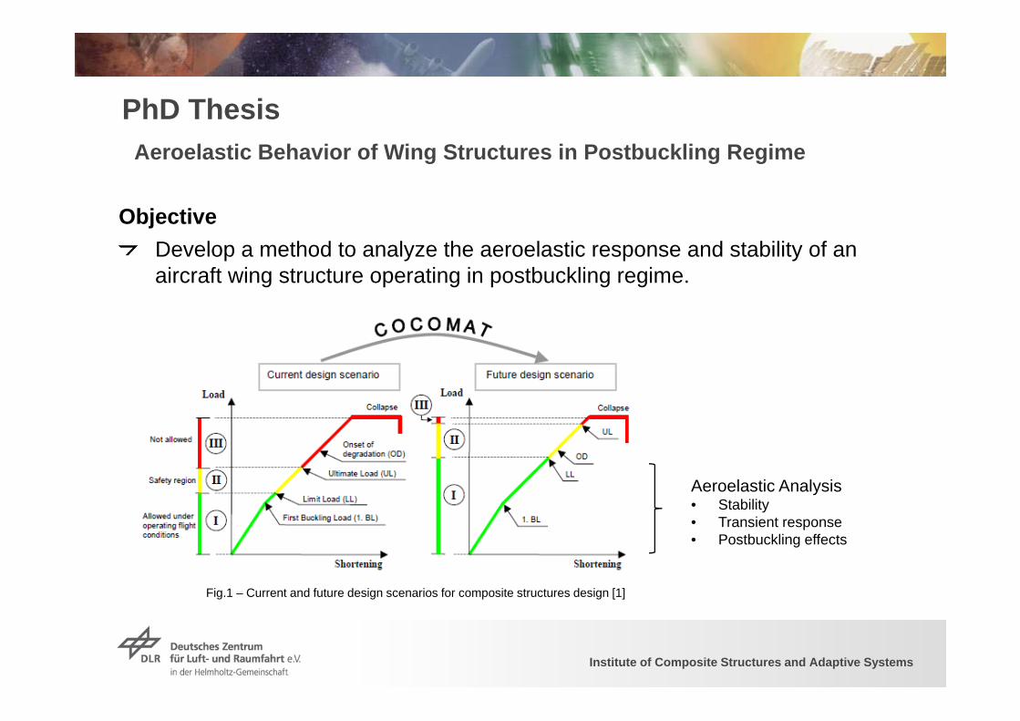
PhD ThesisAeroelastic Behavior of Wing Structures in Postbuckling Regime
Aeroelastic Analysis• Stability• Transient response• Postbuckling effects
Fig.1 – Current and future design scenarios for composite structures design [1]
ObjectiveDevelop a method to analyze the aeroelastic response and stability of an aircraft wing structure operating in postbuckling regime.
Institute of Composite Structures and Adaptive Systems 55
Contribute to recent efforts to achieve weight and costreductions in composite wing structures allowing themto work in postbuckling regime when subjected to limitloads.
Investigate the effect of stiffness changes caused bypostbuckling on the aeroelastic response and stabilityof composite wings.
Provide additional guidelines for the design inpostbuckling regime of new light-weight compositewing structures taking into account the aeroelasticbehavior.
5
Motivations
Institute of Composite Structures and Adaptive Systems 6
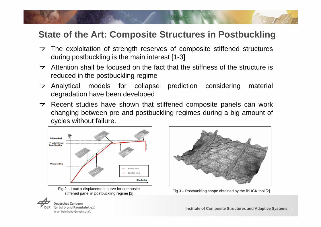
State of the Art: Composite Structures in PostbucklingThe exploitation of strength reserves of composite stiffened structuresduring postbuckling is the main interest [1-3]Attention shall be focused on the fact that the stiffness of the structure isreduced in the postbuckling regimeAnalytical models for collapse prediction considering materialdegradation have been developedRecent studies have shown that stiffened composite panels can workchanging between pre and postbuckling regimes during a big amount ofcycles without failure.
Fig.3 – Postbuckling shape obtained by the iBUCK tool [2]Fig.2 – Load x displacement curve for composite stiffened panel in postbuckling regime [2]
Institute of Composite Structures and Adaptive Systems
State of the Art: Composite Structures in Postbuckling
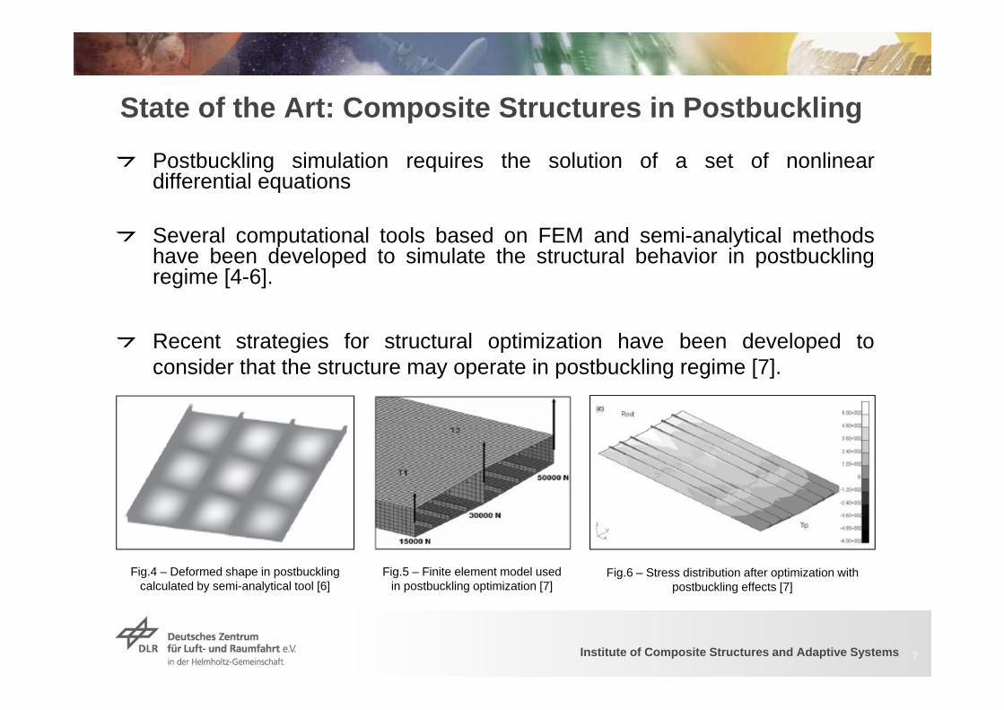
Postbuckling simulation requires the solution of a set of nonlineardifferential equations
Several computational tools based on FEM and semi-analytical methodshave been developed to simulate the structural behavior in postbucklingregime [4-6].
Recent strategies for structural optimization have been developed toconsider that the structure may operate in postbuckling regime [7].
7
Fig.4 – Deformed shape in postbuckling calculated by semi-analytical tool [6]
Fig.5 – Finite element model used in postbuckling optimization [7]
Fig.6 – Stress distribution after optimization with postbuckling effects [7]
Institute of Composite Structures and Adaptive Systems
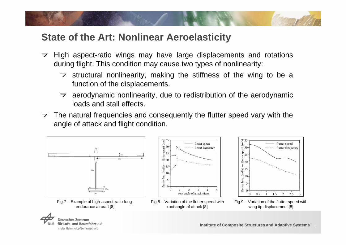
State of the Art: Nonlinear AeroelasticityHigh aspect-ratio wings may have large displacements and rotationsduring flight. This condition may cause two types of nonlinearity:
structural nonlinearity, making the stiffness of the wing to be afunction of the displacements.aerodynamic nonlinearity, due to redistribution of the aerodynamicloads and stall effects.
The natural frequencies and consequently the flutter speed vary with theangle of attack and flight condition.
8
Fig.7 – Example of high-aspect-ratio-long-endurance aircraft [8]
Fig.8 – Variation of the flutter speed with root angle of attack [8]
Fig.9 – Variation of the flutter speed with wing tip displacement [8]
Institute of Composite Structures and Adaptive Systems
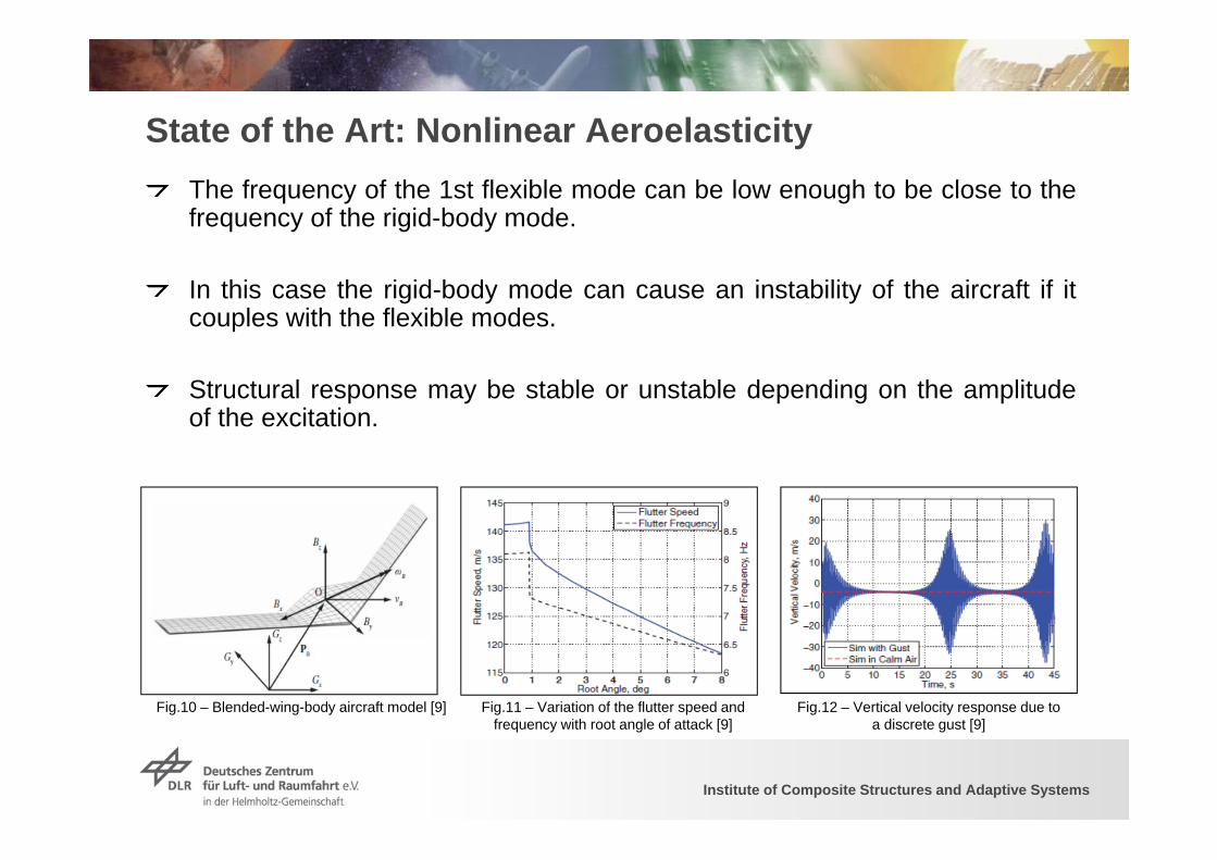
State of the Art: Nonlinear AeroelasticityThe frequency of the 1st flexible mode can be low enough to be close to thefrequency of the rigid-body mode.
In this case the rigid-body mode can cause an instability of the aircraft if itcouples with the flexible modes.
Structural response may be stable or unstable depending on the amplitudeof the excitation.
Fig.10 – Blended-wing-body aircraft model [9] Fig.11 – Variation of the flutter speed and frequency with root angle of attack [9]
Fig.12 – Vertical velocity response due to a discrete gust [9]
Institute of Composite Structures and Adaptive Systems
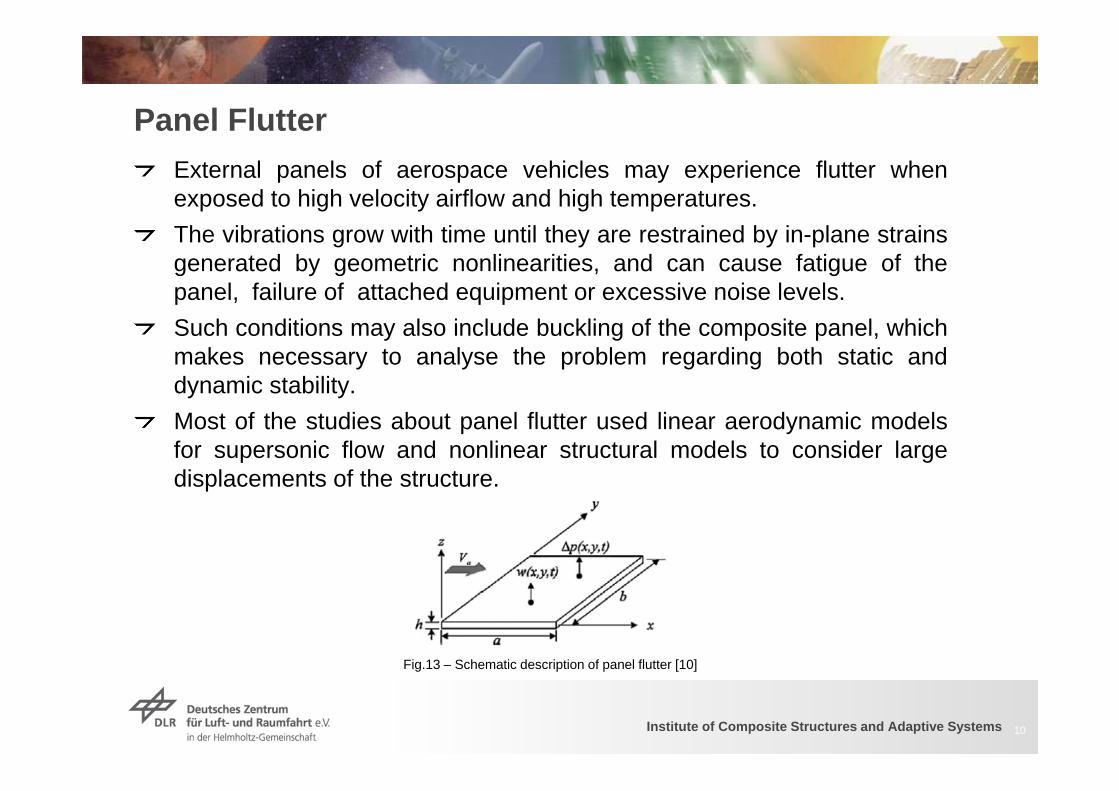
Panel FlutterExternal panels of aerospace vehicles may experience flutter whenexposed to high velocity airflow and high temperatures.The vibrations grow with time until they are restrained by in-plane strainsgenerated by geometric nonlinearities, and can cause fatigue of thepanel, failure of attached equipment or excessive noise levels.Such conditions may also include buckling of the composite panel, whichmakes necessary to analyse the problem regarding both static anddynamic stability.Most of the studies about panel flutter used linear aerodynamic modelsfor supersonic flow and nonlinear structural models to consider largedisplacements of the structure.
10
Fig.13 – Schematic description of panel flutter [10]
Institute of Composite Structures and Adaptive Systems
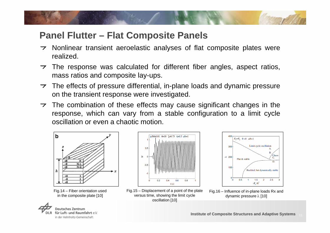
Panel Flutter – Flat Composite PanelsNonlinear transient aeroelastic analyses of flat composite plates wererealized.The response was calculated for different fiber angles, aspect ratios,mass ratios and composite lay-ups.The effects of pressure differential, in-plane loads and dynamic pressureon the transient response were investigated.The combination of these effects may cause significant changes in theresponse, which can vary from a stable configuration to a limit cycleoscillation or even a chaotic motion.
11
Fig.14 – Fiber orientation used in the composite plate [10]
Fig.15 – Displacement of a point of the plate versus time, showing the limit cycle
oscillation [10]
Fig.16 – Influence of in-plane loads Rx and dynamic pressure [10]
Institute of Composite Structures and Adaptive Systems
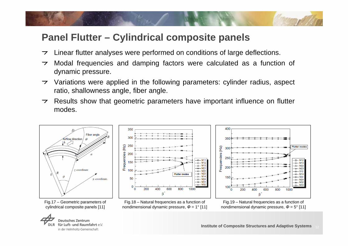
Panel Flutter – Cylindrical composite panelsLinear flutter analyses were performed on conditions of large deflections.Modal frequencies and damping factors were calculated as a function ofdynamic pressure.Variations were applied in the following parameters: cylinder radius, aspectratio, shallowness angle, fiber angle.Results show that geometric parameters have important influence on fluttermodes.
12
Fig.17 – Geometric parameters of cylindrical composite panels [11]
Fig.18 – Natural frequencies as a function of nondimensional dynamic pressure, Φ = 1° [11]
Fig.19 – Natural frequencies as a function of nondimensional dynamic pressure, Φ = 5° [11]
Institute of Composite Structures and Adaptive Systems
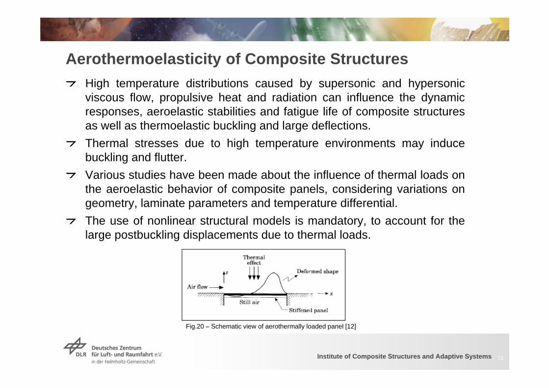
Aerothermoelasticity of Composite StructuresHigh temperature distributions caused by supersonic and hypersonicviscous flow, propulsive heat and radiation can influence the dynamicresponses, aeroelastic stabilities and fatigue life of composite structuresas well as thermoelastic buckling and large deflections.Thermal stresses due to high temperature environments may inducebuckling and flutter.Various studies have been made about the influence of thermal loads onthe aeroelastic behavior of composite panels, considering variations ongeometry, laminate parameters and temperature differential.The use of nonlinear structural models is mandatory, to account for thelarge postbuckling displacements due to thermal loads.
13
Fig.20 – Schematic view of aerothermally loaded panel [12]
Institute of Composite Structures and Adaptive Systems
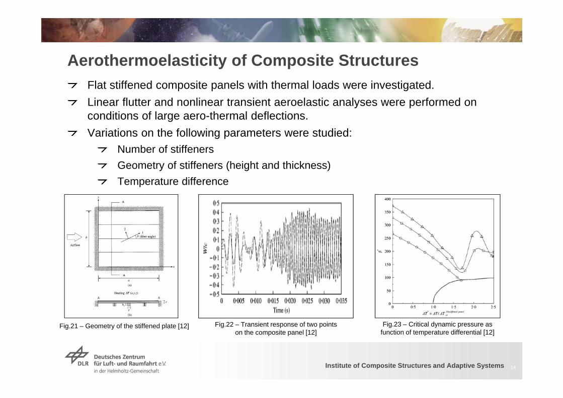
Aerothermoelasticity of Composite StructuresFlat stiffened composite panels with thermal loads were investigated.Linear flutter and nonlinear transient aeroelastic analyses were performed onconditions of large aero-thermal deflections.Variations on the following parameters were studied:
Number of stiffenersGeometry of stiffeners (height and thickness)Temperature difference
14
Fig.21 – Geometry of the stiffened plate [12] Fig.23 – Critical dynamic pressure as function of temperature differential [12]
Fig.22 – Transient response of two points on the composite panel [12]
Institute of Composite Structures and Adaptive Systems
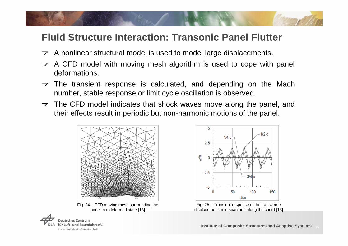
Fluid Structure Interaction: Transonic Panel FlutterA nonlinear structural model is used to model large displacements.A CFD model with moving mesh algorithm is used to cope with paneldeformations.The transient response is calculated, and depending on the Machnumber, stable response or limit cycle oscillation is observed.The CFD model indicates that shock waves move along the panel, andtheir effects result in periodic but non-harmonic motions of the panel.
15
Fig. 24 – CFD moving mesh surrounding the panel in a deformed state [13]
Fig. 25 – Transient response of the transverse displacement, mid span and along the chord [13]
Institute of Composite Structures and Adaptive Systems
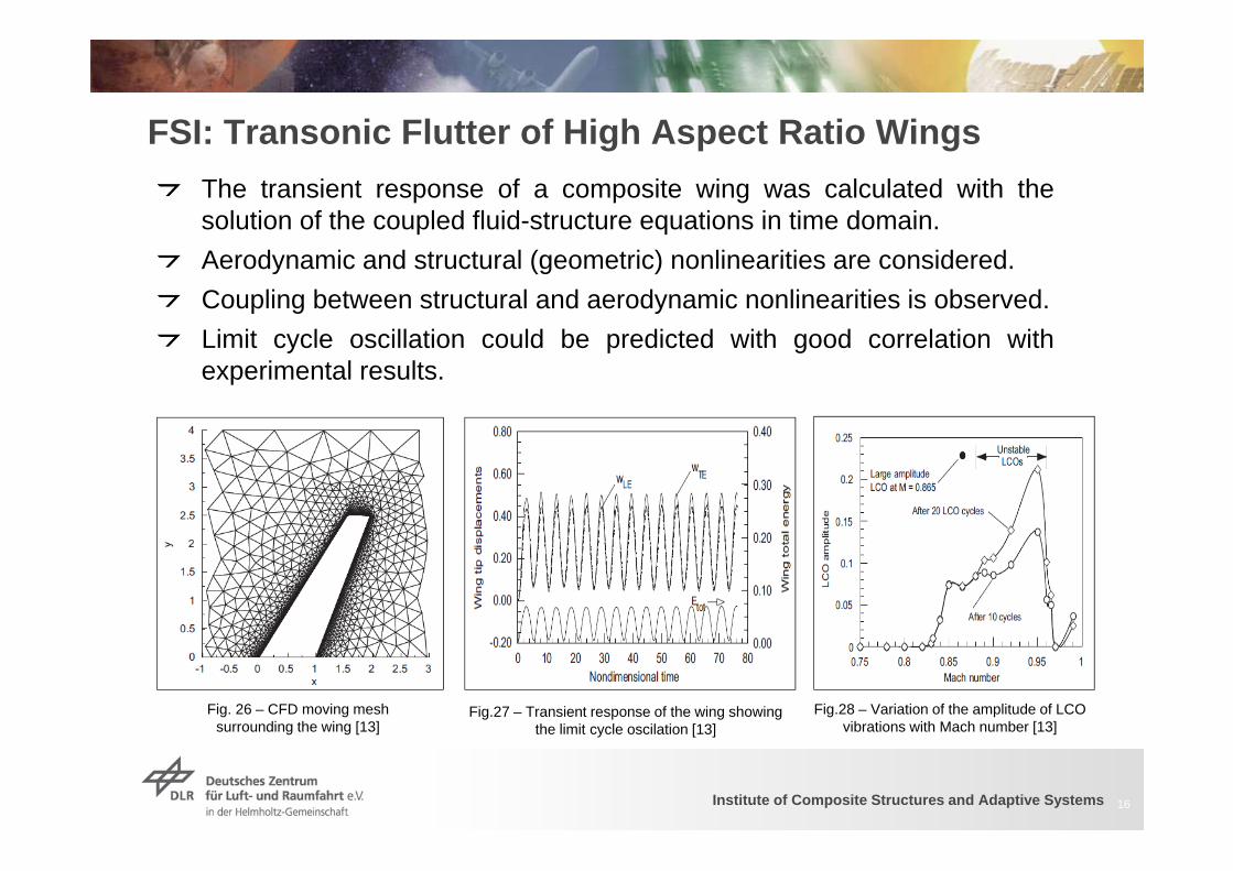
FSI: Transonic Flutter of High Aspect Ratio WingsThe transient response of a composite wing was calculated with thesolution of the coupled fluid-structure equations in time domain.Aerodynamic and structural (geometric) nonlinearities are considered.Coupling between structural and aerodynamic nonlinearities is observed.Limit cycle oscillation could be predicted with good correlation withexperimental results.
16
Fig. 26 – CFD moving mesh surrounding the wing [13]
Fig.27 – Transient response of the wing showing the limit cycle oscilation [13]
Fig.28 – Variation of the amplitude of LCO vibrations with Mach number [13]
Institute of Composite Structures and Adaptive Systems
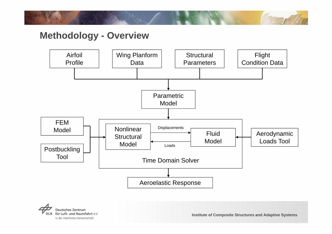
Methodology - Overview
Airfoil Profile
Structural Parameters
Flight Condition Data
Parametric Model
Fluid Model
Nonlinear Structural
Model
Aeroelastic Response
Wing Planform Data
FEMModel
PostbucklingTool Time Domain Solver
Displacements
Loads
Aerodynamic Loads Tool
Institute of Composite Structures and Adaptive Systems
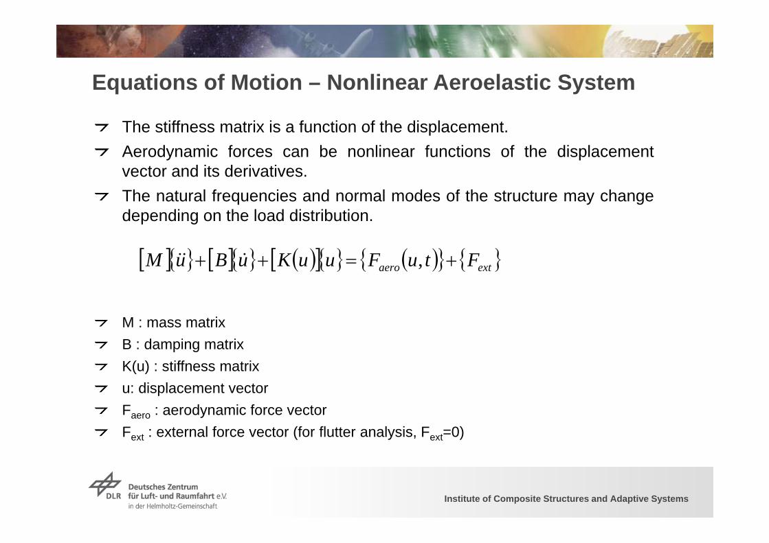
Equations of Motion – Nonlinear Aeroelastic System
extaero FtuFuuKuBuM ,
The stiffness matrix is a function of the displacement.Aerodynamic forces can be nonlinear functions of the displacementvector and its derivatives.The natural frequencies and normal modes of the structure may changedepending on the load distribution.
M : mass matrixB : damping matrixK(u) : stiffness matrixu: displacement vectorFaero : aerodynamic force vectorFext : external force vector (for flutter analysis, Fext=0)
Institute of Composite Structures and Adaptive Systems
Open Questions
Postbuckling design may be used to decrease weight and increase theload-carrying capacity, but what are the effects on aeroelasticity ?If a wing or fuselage structure changes its condition between prebucklingand postbuckling during a gust excitation, what is the influence on theaeroelastic response ?What is the best way to design composite wing and fuselage structuresworking in postbuckling regime and having the best compromise withaeroelastic response and stability ?
19
Institute of Composite Structures and Adaptive Systems
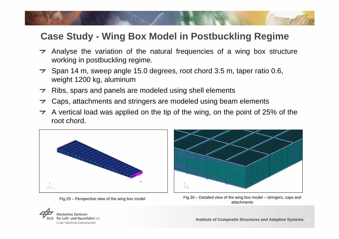
Case Study - Wing Box Model in Postbuckling RegimeAnalyse the variation of the natural frequencies of a wing box structureworking in postbuckling regime.Span 14 m, sweep angle 15.0 degrees, root chord 3.5 m, taper ratio 0.6, weight 1200 kg, aluminumRibs, spars and panels are modeled using shell elementsCaps, attachments and stringers are modeled using beam elementsA vertical load was applied on the tip of the wing, on the point of 25% of theroot chord.
20
Fig.29 – Perspective view of the wing box model Fig.30 – Detailed view of the wing box model – stringers, caps and attachments
Institute of Composite Structures and Adaptive Systems
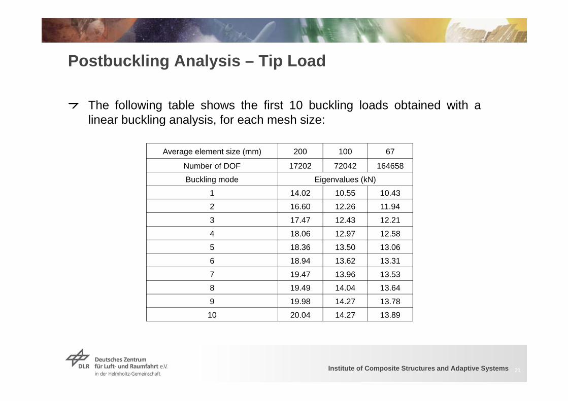
Postbuckling Analysis – Tip Load
The following table shows the first 10 buckling loads obtained with alinear buckling analysis, for each mesh size:
21
Average element size (mm) 200 100 67
Number of DOF 17202 72042 164658
Buckling mode Eigenvalues (kN)
1 14.02 10.55 10.43
2 16.60 12.26 11.94
3 17.47 12.43 12.21
4 18.06 12.97 12.58
5 18.36 13.50 13.06
6 18.94 13.62 13.31
7 19.47 13.96 13.53
8 19.49 14.04 13.64
9 19.98 14.27 13.78
10 20.04 14.27 13.89
Institute of Composite Structures and Adaptive Systems
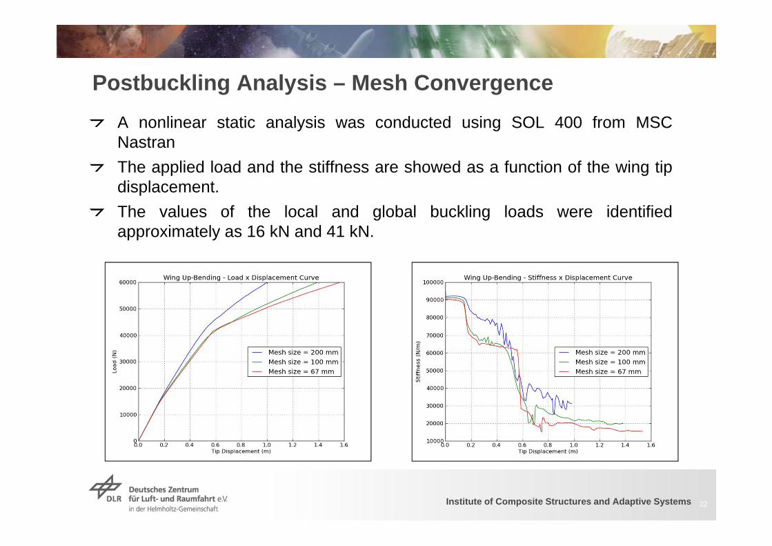
Postbuckling Analysis – Mesh ConvergenceA nonlinear static analysis was conducted using SOL 400 from MSCNastranThe applied load and the stiffness are showed as a function of the wing tipdisplacement.The values of the local and global buckling loads were identifiedapproximately as 16 kN and 41 kN.
22
Institute of Composite Structures and Adaptive Systems
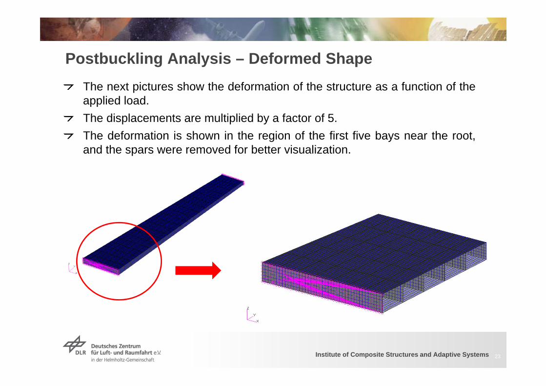
Postbuckling Analysis – Deformed Shape
23
The next pictures show the deformation of the structure as a function of theapplied load.The displacements are multiplied by a factor of 5.The deformation is shown in the region of the first five bays near the root,and the spars were removed for better visualization.
Institute of Composite Structures and Adaptive Systems
Postbuckling Analysis – Deformed Shape
24
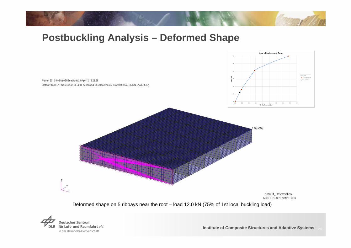
Deformed shape on 5 ribbays near the root – load 12.0 kN (75% of 1st local buckling load)

Institute of Composite Structures and Adaptive Systems
Postbuckling Analysis – Deformed Shape
25
Deformed shape on 5 ribbays near the root – load 18.0 kN (113% of 1st local buckling load)
Institute of Composite Structures and Adaptive Systems
Postbuckling Analysis – Deformed Shape
26
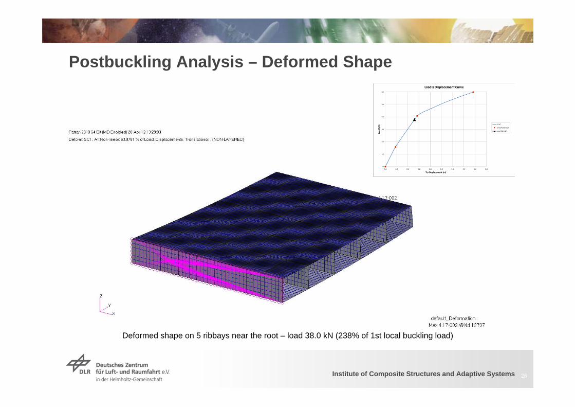
Deformed shape on 5 ribbays near the root – load 38.0 kN (238% of 1st local buckling load)

Institute of Composite Structures and Adaptive Systems
Postbuckling Analysis – Deformed Shape
27
Deformed shape on 5 ribbays near the root – load 45.0 kN (281% of 1st local buckling load)
Institute of Composite Structures and Adaptive Systems
Postbuckling Analysis – Deformed Shape
28
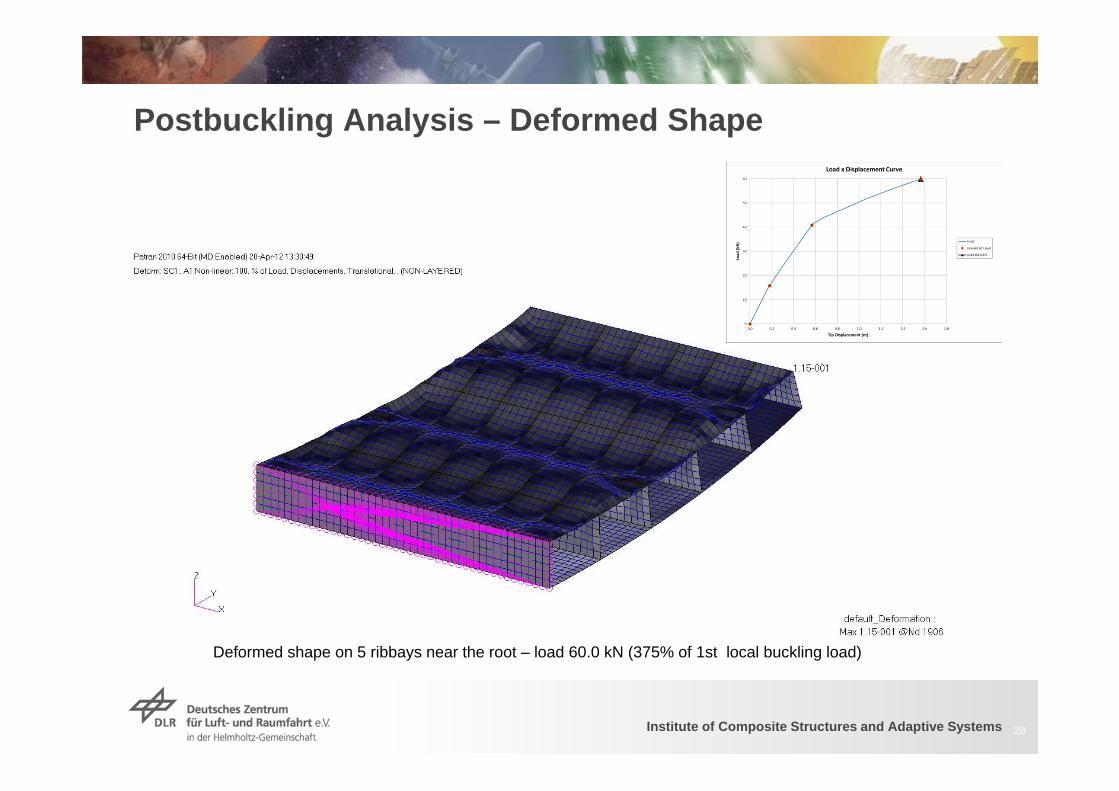
Deformed shape on 5 ribbays near the root – load 60.0 kN (375% of 1st local buckling load)
Institute of Composite Structures and Adaptive Systems
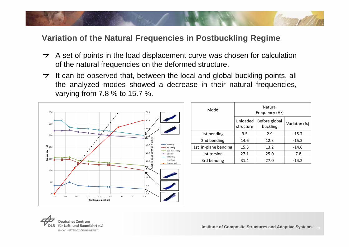
Variation of the Natural Frequencies in Postbuckling Regime
A set of points in the load displacement curve was chosen for calculationof the natural frequencies on the deformed structure.It can be observed that, between the local and global buckling points, allthe analyzed modes showed a decrease in their natural frequencies,varying from 7.8 % to 15.7 %.
29
Mode Natural Frequency (Hz)
Unloaded structure
Before global buckling Variaton (%)
1st bending 3.5 2.9 ‐15.72nd bending 14.6 12.3 ‐15.2
1st in‐plane bending 15.5 13.2 ‐14.61st torsion 27.1 25.0 ‐7.83rd bending 31.4 27.0 ‐14.2
Institute of Composite Structures and Adaptive Systems 30
ConclusionsStructural and aerodynamic nonlinearities may cause a significantchange in the dynamic and aeroelastic behavior of a structureThe natural frequencies of a wing structure may be significantly affectedif the wing is operating in postbuckling regime
Next StepsIntroduce composite parts on the wing modelIncrease the level of details of the wing structureImprove the mass distribution representationApply a realistic aerodynamic load distribution on the structureEvaluate the effect of postbuckling on the flutter speed and transientresponse due to a gustInvestigate the effect of different wing configurations, including enginesand winglets

Institute of Composite Structures and Adaptive Systems
Questions ?
Thank you !
Institute of Composite Structures and Adaptive Systems
References1. Degenhardt R et al. COCOMAT – “Improved Material Exploitation of Composite Airframe Structures by Accurate
Simulation of Postbuckling and Collapse”. Composite Structures 73 (2006) 175–1782. Degenhardt R, Kling A, Orifici AC, Thomson RS. “Design and analysis of stiffened composite panels including post-
buckling and collapse”. Computers and Structures 86 (2008) 919–929.3. Ghilai G,Feldman E,David A.“COCOMAT Design and Analysis Guidelines for CFRP-Stiffened Panels in Buckling
and Postbuckling”. International Journal of Structural Stability and Dynamics, Vol.10, No.4 (2010) pp 917-9264. Doreille M, Merazzi S, Rohwer K, Degenhardt R. “Post-buckling Analysis of Composite Shell Structures – Towards
Fast and Accurate Tools with Implicit FEM Methods”. International Journal of Structural Stability and Dynamics,2009
5. Orifici AC, Thomson RS, Degenhardt R, Bisagni C, Bayandor J. “An Analysis Tool For Design and Certification ofPostbuckling Composite Aerospace Structures”. April 2009
6. Bisagni C, Vescovini R.“Analytical formulation for local buckling and post-buckling analysis of stiffened laminatedpanels.” Thin-Walled Structures 47(2009), pp. 318–334
7. Qu S, Kennedy D, Featherston CA. “A multilevel framework for optimization of an aircraft wing incorporatingpostbuckling effects”. Proceedings of the Institution of Mechanical Engineers, Part G: Journal of AerospaceEngineering published online 9 November 2011
8. Patil, M. J., Hodges, D. H., and Cesnik, C. E. S., “Nonlinear Aeroelasticity and Flight Dynamics of High-AltitudeLong-Endurance Aircraft,” Journal of Aircraft, Vol. 38, No. 1, 2001, pp. 88–94. doi:10.2514/2.2738
9. Su W, Cesnik CES. “Nonlinear Aeroelasticity of a Very Flexible Blended-Wing-Body Aircraft”. Journal of Aircraft ,Vol. 47, No. 5, September–October 2010
10. Kouchakzadeh M. A., Rasekh M., Haddadpour H. “Panel flutter analysis of general laminated composite plates .Composite Structures 92 (2010) 2906–2915“
11. Oha IK, Kim DH. “Vibration characteristics and supersonic flutter of cylindrical composite panels with largethermoelastic deflections “. Composite Structures 90 (2009) 208–216
12. Oh IK, Lee I. “Nonlinear transient response of fluttering stiffened composite plates subject to thermal load “. Journalof Sound and Vibration (2001) 245(4), 715-736
13. Bendiksen OO, Seber G. “Fluid–structure interactions with both structural and fluid nonlinearities“. Journal of Soundand Vibration 315 (2008) 664–684


![Impact and Postbuckling Analyses - imechanicaPostbuckling Analyses Geometric Imperfections for Postbuckling Analyses • Using buckling modes for imperfections]..](https://img.pdfslide.net/doc/110x75/5e279cdbcab01659037bd7a7/impact-and-postbuckling-analyses-imechanica-postbuckling-analyses-geometric-imperfections.jpg)


![Aeroelastic Stability Analysis of a Darrieus Wind Turbine · [GI] = diagonal generalized mass matrix [2EUNGI] ... [GIUN2] = diagonal generalized stiffness matrix E = structural damping](https://img.pdfslide.net/doc/110x75/5e3f3d2f6e7f9028a159bcde/aeroelastic-stability-analysis-of-a-darrieus-wind-turbine-gi-diagonal-generalized.jpg)