Embed Size (px)
Citation preview
Study of Drill String Safety Valves
ADAM T. BOURGOYNE, JR., LSU
September 6, 2002
Craft and Hawkins Department of Petroleum EngineeringBaton Rouge, LA 70803
225 578 5215
Table of Contents
EXECUTIVE SUMMARY ............................... 2
ACKNOWLEDGEMENT ............................................................ 4
INTRODUCTION ............................................ 5
INDUSTRY AND LITERATURE SURVEY.... 8
Common Modes of Failure...................................................... 8Literature and Patent Search................................................. 12
DEVELOPMENT OF NOVEL DSSV DESIGN......................................................................... 15
PHASE II DESIGN ..................................................................... 15PHASE II STATIC TEST RESULTS......................................... 18Torque to Open under Differential Pressure ...................... 19Torque to Close DSSV under Equalized Pressure ............. 20Post Test Valve Inspection................................................... 21Finite Element Analysis of Bearing Bore ............................ 21PHASE III DESIGN.................................................................... 24Design Changes ..................................................................... 25Testing of Belleville Springs................................................. 27Assembly Procedure.............................................................. 28Phase III DSSV Test Program............................................... 29Theoretical Operating Torque.............................................. 31Test Results ............................................................................ 34
DEVELOPMENT OF DSSV STORAGESTAND............................................................ 38
DESIGN ..................................................................................... 38Hydraulic Pump ...................................................................... 39Hydraulic Cylinders ............................................................... 40Fluid Reservoir........................................................................ 40Hydraulic Fluid ....................................................................... 41Control Panel........................................................................... 41Storage Structure.................................................................... 41ASSEMBLY AND TESTING ..................................................... 42
CONCLUSIONS ANDRECOMMENDATIONS................................ 44
CONCLUSIONS......................................................................... 45RECOMMENDATIONS............................................................. 45
BIBLIOGRAPHY........................................... 46
PHASE III PROTOTYPE DSSV .................... 47
PHASE IV PROTOTYPE DSSVSTORAGE STAND......................................... 58
E X E C U T I V E S U M M A R Y
2
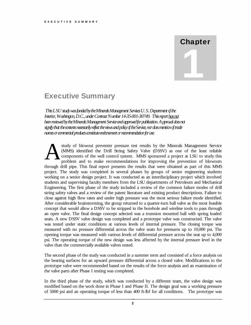
Executive Summary
This LSU study was funded by the Minerals Management Services U. S. Department of theInterior, Washington, D.C., under Contract Number 14-35-001-30749. This report has notbeen reviewed by the Minerals Management Service and approved for publication. Approval does notsignify that the contents necessarily reflect the views and policy of the Service, nor does mention of tradenames or commercial products constitute endorsement or recommendation for use.
study of blowout preventer pressure test results by the Minerals Management Service(MMS) identified the Drill String Safety Valve (DSSV) as one of the least reliablecomponents of the well control system. MMS sponsored a project at LSU to study thisproblem and to make recommendations for improving the prevention of blowouts
through drill pipe. This final report presents the results that were obtained as part of this MMSproject. The study was completed in several phases by groups of senior engineering studentsworking on a senior design project. It was conducted as an interdisciplinary project which involvedstudents and supervising faculty members from the LSU departments of Petroleum and MechanicalEngineering. The first phase of the study included a review of the common failure modes of drillstring safety valves and a review of the patent literature and existing product descriptions. Failure toclose against high flow rates and under high pressure was the most serious failure mode identified.After considerable brainstorming, the group returned to a quarter-turn ball valve as the most feasibleconcept that would allow a DSSV to be stripped in the borehole and wireline tools to pass throughan open valve. The final design concept selected was a trunnion mounted ball with spring loadedseats. A new DSSV valve design was completed and a prototype valve was constructed. The valvewas tested under static conditions at various levels of internal pressure. The closing torque wasmeasured with no pressure differential across the valve seats for pressures up to 10,000 psi. Theopening torque was measured with various levels of differential pressure across the seat up to 4,000psi. The operating torque of the new design was less affected by the internal pressure level in thevalve than the commercially available valves tested.
The second phase of the study was conducted in a summer term and consisted of a force analysis onthe bearing surfaces for an upward pressure differential across a closed valve. Modifications to theprototype valve were recommended based on the results of the force analysis and an examination ofthe valve parts after Phase I testing was completed.
In the third phase of the study, which was conducted by a different team, the valve design wasmodified based on the work done in Phase I and Phase II. The design goal was a working pressureof 5000 psi and an operating torque of less than 400 ft-lbf for all conditions. The prototype was
Chapter
1
A

E X E C U T I V E S U M M A R Y
3
modified and a flow loop for testing drillstring safety valves under flowing conditions at a desiredflow rate and internal pressure was also constructed. Theoretical operating torque versus differentialpressure curves were calculated for the prototype design prior to testing. The prototype design wastested along with several of the most commonly used commercially available drillstring safety valves.Although the measured operating torque was higher than the theoretical values calculated, the newdesign met the design goal.
It was noted during the Phase III testing that the operating torque requirements of a commerciallyavailable DSSV that was tested with the new prototype had increased significantly over previouslymeasurements made during early tests. It was hypothesized that mud debris from testing andweathering of valve components during periods of outside storage had increased friction betweenthe valve moving parts. Internal clearances could also have changed after conduction a number ofvalve operations under high pressure and high torque conditions. Phase IV of the study was thedesign and construction of a valve storage system capable of maintaining a drillstring safety valve in alike new condition on the rig floor in an offshore environment. A storage stand was designed thatcould store up to four DSSV units submerged in “environmentally friendly” oil and allow any of thefour valves to be retrieved with an air hoist in less than 10 seconds. Each DSSV is stored in acylindrical chamber and rests on a piston that can quickly elevate the DSSV by opening a valve thatallows hydraulic pressure to be applied beneath the piston. The storage stand was demonstrated atan LSU/MMS Well Control Workshop.
As a result of the study, the following recommendations are made regarding the use of Drill StringSafety Valves:
1. The DSSV intended for use as a stabbing valve to stop flow through the drillstring during trippingoperations should not be used in the drillstring for other operations. The stabbing valve should bemaintained in a “like-new“ condition and used only during periodic pressure testing with fresh water.
2. Operators and/or drilling contractors should check threads, valve wrench, and lift sub on the stabbingvalve and actuate the stabbing valve close and open each tour.
3. Operators and/or drilling contractors should use a drillstring float whenever practical to provideredundant protection against a high-rate flow through the drill-string during tripping operations.
4. When floats are not used, shear rams are recommended for redundant protection against blowoutsthrough the drillstring during tripping operations.
5. Drill String Safety Valves should not be the only means for stopping flow from the drillstring at thesurface when reverse circulating the well during completion operations. Flow should be routed throughhydraulically operated valves and a choke manifold.
6. Drill string safety valves should not be the only means for stopping flow through the drill string whensignificant piping and flow restrictions are present above the valve.
E X E C U T I V E S U M M A R Y
4
AcknowledgementThe work for this interdisciplinary project was supervised by Dr. A. T. (Ted) Bourgoyne, Jr. and Dr.L. S. (Scott) Stephens. The work was done by the following students:
Angelique Lawless;
Karl Eubanks;
Richard Duncan;
Daniel Reed;
Arthur J. Boudreaux;
Lance Fish;
Mark A. Casemore;
Elliot D. Coleman;
Thomas T. Core, Jr;
Brad W. Smith;
Jason Micas;
Jarield Francis;
Brian Puls; and
Hugh Kilpatrick.
Jim Cunningham of M&M International was the industry sponsor for the project and providedvaluable guidance and assistance. Mr. Cunningham also donated considerable shop time and suppliesand made his manufacturing and testing facilities available to the students on a number of occasions.
I N T R O D U C T I O N
5
Introduction
In this chapter, the basic drill string safety valve terminology will be reviewed. In addition, the currentproblem areas identified in this study from a literature review and from consultation with industryrepresentatives will be presented.
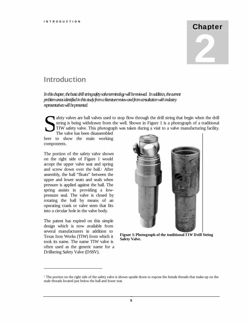
afety valves are ball valves used to stop flow through the drill string that begin when the drillstring is being withdrawn from the well. Shown in Figure 1 is a photograph of a traditionalTIW safety valve. This photograph was taken during a visit to a valve manufacturing facility.The valve has been disassembled
here to show the main workingcomponents.
The portion of the safety valve shownon the right side of Figure 1 wouldaccept the upper valve seat and springand screw down over the ball.1 Afterassembly, the ball “floats” between theupper and lower seats and seals whenpressure is applied against the ball. Thespring assists in providing a low-pressure seal. The valve is closed byrotating the ball by means of anoperating crank or valve stem that fitsinto a circular hole in the valve body.
The patent has expired on this simpledesign which is now available fromseveral manufacturers in addition toTexas Iron Works (TIW) from which ittook its name. The name TIW valve isoften used as the generic name for aDrillstring Safety Valve (DSSV).
1 The portion on the right side of the safety valve is shown upside down to expose the female threads that make-up on themale threads located just below the ball and lower seat.
Chapter
2S
Figure 1: Photograph of the traditional TIW Drill StringSafety Valve.
I N T R O D U C T I O N
6
Shown in Figure 2 are the traditional locationsof safety valves which include upper andlower kelly cocks as well as a stabbing valve.Government regulations require that a safetyvalve and operating wrench be maintained onthe rig floor at all times.
Displayed in Figure 3 is a photograph of asafety valve made-up on top of a section ofdrillpipe which has been cutaway so that theball and seats may be observed. The safetyvalve shown is a one-piece valve design thateliminates the need for threads in the valvebody area. This not only decreases the numberof possible leak paths, but also eliminates theproblem of ball locking due to excessivetorque. The valve is operated by means of anoperating-wrench that is inserted into the valvestem and turned one-quarter turn.
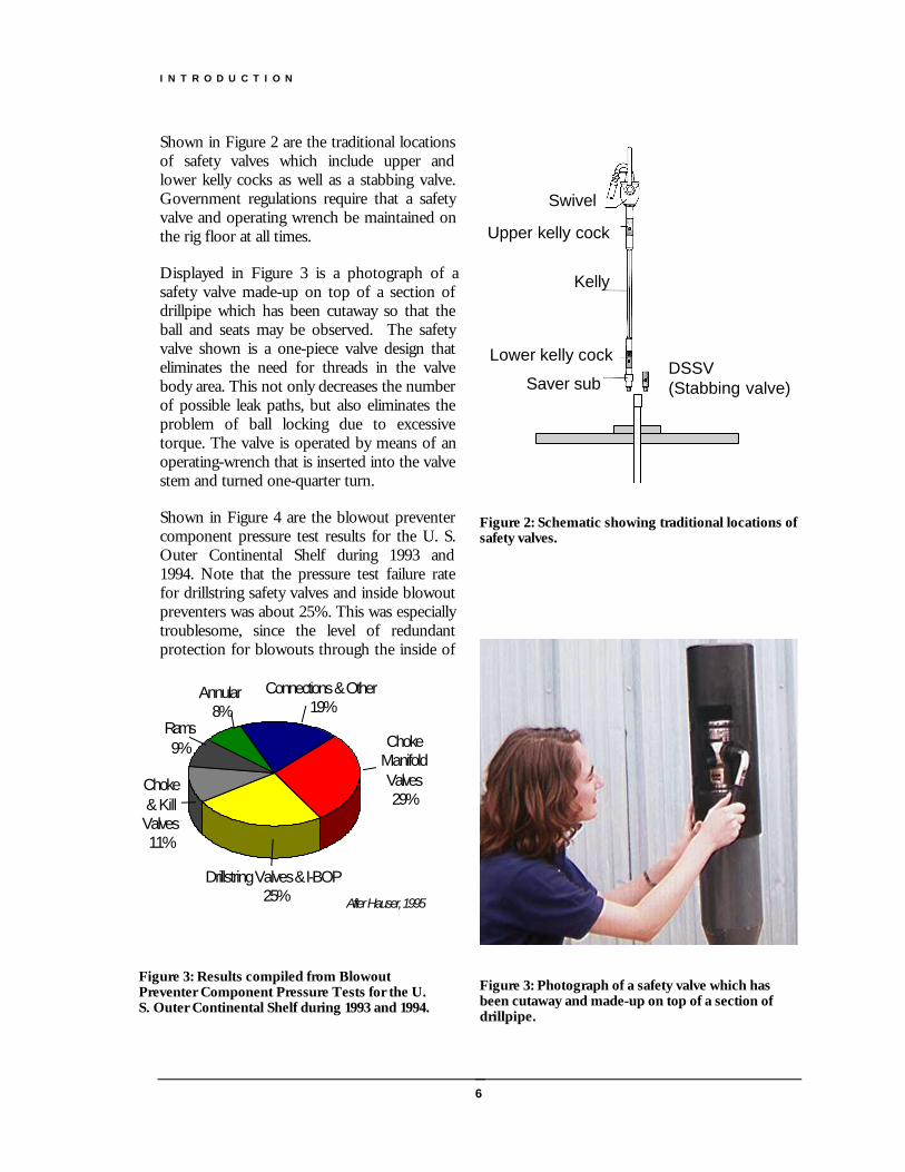
Shown in Figure 4 are the blowout preventercomponent pressure test results for the U. S.Outer Continental Shelf during 1993 and1994. Note that the pressure test failure ratefor drillstring safety valves and inside blowoutpreventers was about 25%. This was especiallytroublesome, since the level of redundantprotection for blowouts through the inside of
Swivel
Lower kelly cock
Kelly
Saver subDSSV(Stabbing valve)
Upper kelly cock
Figure 2: Schematic showing traditional locations ofsafety valves.
Figure 3: Photograph of a safety valve which hasbeen cutaway and made-up on top of a section ofdrillpipe.
Drillstring Valves & I-BOP 25%
Choke Manifold Valves29%
Connections & Other19%
Choke & Kill Valves11%
Rams9%
Annular8%
After Hauser, 1995
Figure 3: Results compiled from BlowoutPreventer Component Pressure Tests for the U.S. Outer Continental Shelf during 1993 and 1994.
I N T R O D U C T I O N
7
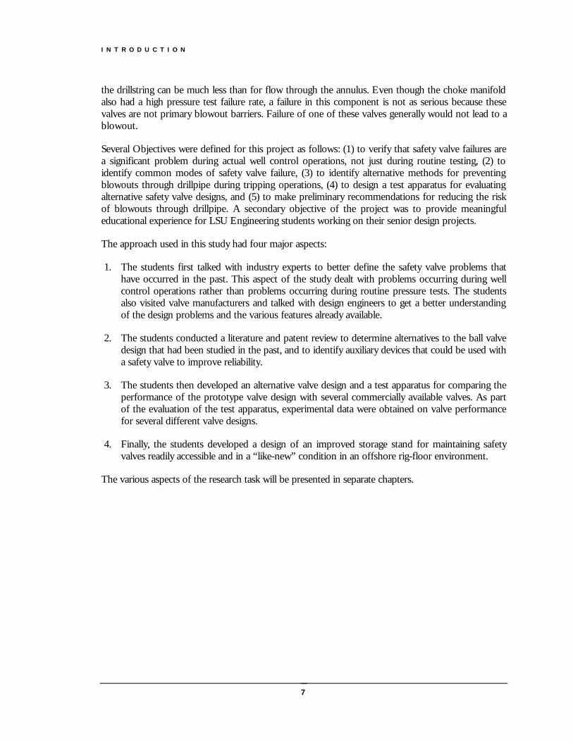
the drillstring can be much less than for flow through the annulus. Even though the choke manifoldalso had a high pressure test failure rate, a failure in this component is not as serious because thesevalves are not primary blowout barriers. Failure of one of these valves generally would not lead to ablowout.
Several Objectives were defined for this project as follows: (1) to verify that safety valve failures area significant problem during actual well control operations, not just during routine testing, (2) toidentify common modes of safety valve failure, (3) to identify alternative methods for preventingblowouts through drillpipe during tripping operations, (4) to design a test apparatus for evaluatingalternative safety valve designs, and (5) to make preliminary recommendations for reducing the riskof blowouts through drillpipe. A secondary objective of the project was to provide meaningfuleducational experience for LSU Engineering students working on their senior design projects.
The approach used in this study had four major aspects:
1. The students first talked with industry experts to better define the safety valve problems thathave occurred in the past. This aspect of the study dealt with problems occurring during wellcontrol operations rather than problems occurring during routine pressure tests. The studentsalso visited valve manufacturers and talked with design engineers to get a better understandingof the design problems and the various features already available.
2. The students conducted a literature and patent review to determine alternatives to the ball valvedesign that had been studied in the past, and to identify auxiliary devices that could be used witha safety valve to improve reliability.
3. The students then developed an alternative valve design and a test apparatus for comparing theperformance of the prototype valve design with several commercially available valves. As partof the evaluation of the test apparatus, experimental data were obtained on valve performancefor several different valve designs.
4. Finally, the students developed a design of an improved storage stand for maintaining safetyvalves readily accessible and in a “like-new” condition in an offshore rig-floor environment.
The various aspects of the research task will be presented in separate chapters.
D E V E L O P M E N T O F N O V E L D S S V D E S I G N
8
Industry and Literature Survey
The results of consultation with industry experts provided much valuable information, some of which hadbeen published in the literature
obil Oil Company conducted an industry survey in 1994 and identified 29 safety valve failuresduring well control operations over an unspecified period. The survey was conducted afterMobil experienced a number of problems in 1993 with stabbing valves leaking after beingstripped into a well in a threatened blowout situation. The survey also identified several
common failure modes for safety valves. The Mobil Oil study also agreed with experiences reported byother industry experts that were consulted.
Common Modes of Failure
The common modes of failure identified in the industry survey conducted by Mobil included:
1. Failure to close due to high torque (valve lock up);
2. Failure to seal due to flow erosion;
3. Failure to seal against pressure from below;
4. Failure to seal against pressure from above;
5. Failure to seal against pressure from outside; and
6. Failures to open due to high torque (valve lock up).
The most serious of these failure modes is failure of the valve to close due to high torque. Blowoutsthat occur due to this failure mode continue to occur. The author is aware of a blowout in 1996 andanother in 2001 that resulted in loss of life after a DSSV could not be closed.2 About 400 ft-lbf isgenerally regarded as an upper limit of torque that can be applied manually with an operating wrench. Ifthe torque required to completely close the valve is exceeded before the valve is fully closed, the failuresassociated with partially closed valves occurs. High torque values are caused by the build up of pressurein the valve as the valve begins to restrict the flow. The pressure pushes the valve stem further into andagainst the valve body and the ball is forced against the upper seat. These two actions create can frictionforces that can not be overcome, especially if the ball and stem dimensions are out of tolerance due to
2 In both cases, other human errors also contributed to the loss of life.
Chapter
3M
D E V E L O P M E N T O F N O V E L D S S V D E S I G N
9
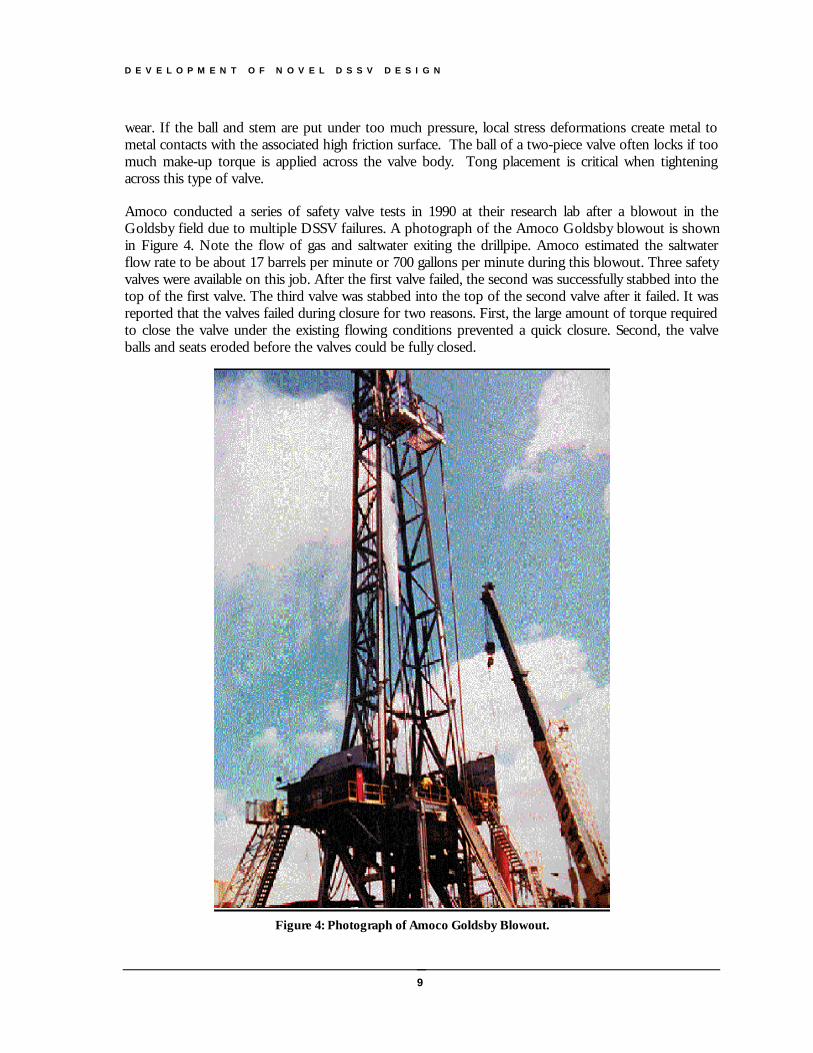
Figure 4: Photograph of Amoco Goldsby Blowout.
wear. If the ball and stem are put under too much pressure, local stress deformations create metal tometal contacts with the associated high friction surface. The ball of a two-piece valve often locks if toomuch make-up torque is applied across the valve body. Tong placement is critical when tighteningacross this type of valve.
Amoco conducted a series of safety valve tests in 1990 at their research lab after a blowout in theGoldsby field due to multiple DSSV failures. A photograph of the Amoco Goldsby blowout is shownin Figure 4. Note the flow of gas and saltwater exiting the drillpipe. Amoco estimated the saltwaterflow rate to be about 17 barrels per minute or 700 gallons per minute during this blowout. Three safetyvalves were available on this job. After the first valve failed, the second was successfully stabbed into thetop of the first valve. The third valve was stabbed into the top of the second valve after it failed. It wasreported that the valves failed during closure for two reasons. First, the large amount of torque requiredto close the valve under the existing flowing conditions prevented a quick closure. Second, the valveballs and seats eroded before the valves could be fully closed.
D E V E L O P M E N T O F N O V E L D S S V D E S I G N
10
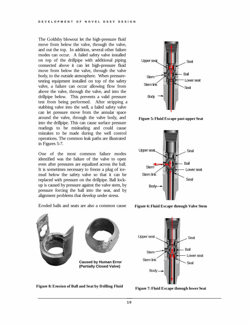
The Goldsby blowout let the high-pressure fluidmove from below the valve, through the valve,and out the top. In addition, several other failuremodes can occur. A failed safety valve installedon top of the drillpipe with additional pipingconnected above it can let high-pressure fluidmove from below the valve, through the valvebody, to the outside atmosphere. When pressure-testing equipment installed on top of the safetyvalve, a failure can occur allowing flow fromabove the valve, through the valve, and into thedrillpipe below. This prevents a valid pressuretest from being performed. After stripping astabbing valve into the well, a failed safety valvecan let pressure move from the annular spacearound the valve, through the valve body, andinto the drillpipe. This can cause surface pressurereadings to be misleading and could causemistakes to be made during the well controloperations. The common leak paths are illustratedin Figures 5-7.
One of the most common failure modesidentified was the failure of the valve to openeven after pressures are equalized across the ball.It is sometimes necessary to freeze a plug of ice-mud below the safety valve so that it can bereplaced with pressure on the drillpipe. Ball lock-up is caused by pressure against the valve stem, bypressure forcing the ball into the seat, and byalignment problems that develop under stress.
Eroded balls and seats are also a common cause
Upper seat
Stem
Stem link
Body
Ball
Seal
Lower seat
Seal
Figure 5: Fluid Escape past upper Seat
Upper seat
Stem
Stem link
Body
Ball
Seal
Lower seat
Seal
Figure 6: Fluid Escape through Valve Stem
Upper seat
Stem
Stem link
Body
Ball
Seal
Lower seat
Seal
Figure 7: Fluid Escape through lower Seat
Caused by Human Error(Partially Closed Valve)
Figure 8: Erosion of Ball and Seat by Drilling Fluid
D E V E L O P M E N T O F N O V E L D S S V D E S I G N
11
of failure identified in this study. The erosioncould be due by flow of mud solids throughthe valve as it is being closed. However, ifthe ball is not aligned perfectly in the openposition, erosion in an upper or lower Kellyvalve will also occur during normal drillingoperations (Figure 8). In addition, erosion iscaused by wireline work done through thevalve. Failed elastomers can also cause leaksthrough the stem and around the valve seats.In addition, stress cracks in the valve bodyor threads also can occur.
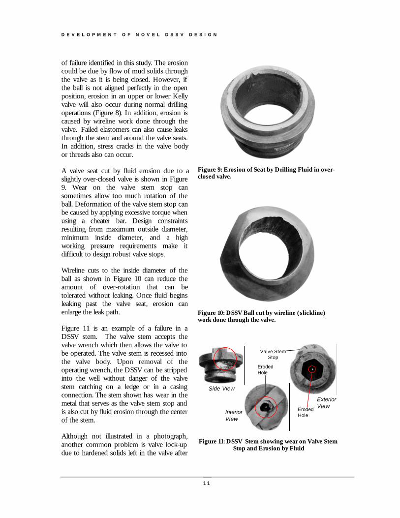
A valve seat cut by fluid erosion due to aslightly over-closed valve is shown in Figure9. Wear on the valve stem stop cansometimes allow too much rotation of theball. Deformation of the valve stem stop canbe caused by applying excessive torque whenusing a cheater bar. Design constraintsresulting from maximum outside diameter,minimum inside diameter, and a highworking pressure requirements make itdifficult to design robust valve stops.
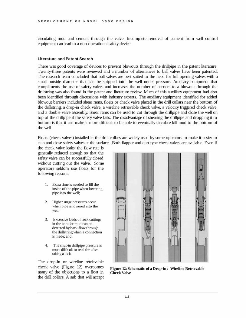
Wireline cuts to the inside diameter of theball as shown in Figure 10 can reduce theamount of over-rotation that can betolerated without leaking. Once fluid beginsleaking past the valve seat, erosion canenlarge the leak path.
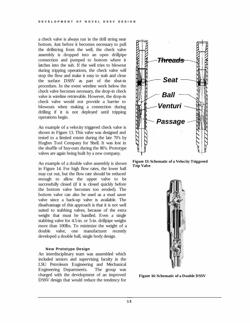
Figure 11 is an example of a failure in aDSSV stem. The valve stem accepts thevalve wrench which then allows the valve tobe operated. The valve stem is recessed intothe valve body. Upon removal of theoperating wrench, the DSSV can be strippedinto the well without danger of the valvestem catching on a ledge or in a casingconnection. The stem shown has wear in themetal that serves as the valve stem stop andis also cut by fluid erosion through the centerof the stem.
Although not illustrated in a photograph,another common problem is valve lock-updue to hardened solids left in the valve after
Figure 9: Erosion of Seat by Drilling Fluid in over-closed valve.
Figure 10: DSSV Ball cut by wireline (slickline)work done through the valve.
Side View
InteriorView
ExteriorView
Valve StemStop
Eroded Hole
Eroded Hole
Figure 11: DSSV Stem showing wear on Valve StemStop and Erosion by Fluid
D E V E L O P M E N T O F N O V E L D S S V D E S I G N
12
circulating mud and cement through the valve. Incomplete removal of cement from well controlequipment can lead to a non-operational safety device.
Literature and Patent Search
There was good coverage of devices to prevent blowouts through the drillpipe in the patent literature.Twenty-three patents were reviewed and a number of alternatives to ball valves have been patented.The research team concluded that ball valves are best suited to the need for full opening valves with asmall outside diameter that can be stripped into the well under pressure. Auxiliary equipment thatcompliments the use of safety valves and increases the number of barriers to a blowout through thedrillstring was also found in the patent and literature review. Much of this auxiliary equipment had alsobeen identified through discussions with industry experts. The auxiliary equipment identified for addedblowout barriers included shear rams, floats or check valve placed in the drill collars near the bottom ofthe drillstring, a drop-in check valve, a wireline retrievable check valve, a velocity triggered check valve,and a double valve assembly. Shear rams can be used to cut through the drillpipe and close the well ontop of the drillpipe if the safety valve fails. The disadvantage of shearing the drillpipe and dropping it tobottom is that it can make it more difficult to be able to eventually circulate kill mud to the bottom ofthe well.
Floats (check valves) installed in the drill collars are widely used by some operators to make it easier tostab and close safety valves at the surface. Both flapper and dart type check valves are available. Even ifthe check valve leaks, the flow rate isgenerally reduced enough so that thesafety valve can be successfully closedwithout cutting out the valve. Someoperators seldom use floats for thefollowing reasons:
1. Extra time is needed to fill theinside of the pipe when loweringpipe into the well;
2. Higher surge pressures occurwhen pipe is lowered into thewell;
3. Excessive loads of rock cuttingsin the annular mud can bedetected by back-flow throughthe drillstring when a connectionis made; and
4. The shut-in drillpipe pressure ismore difficult to read the aftertaking a kick.
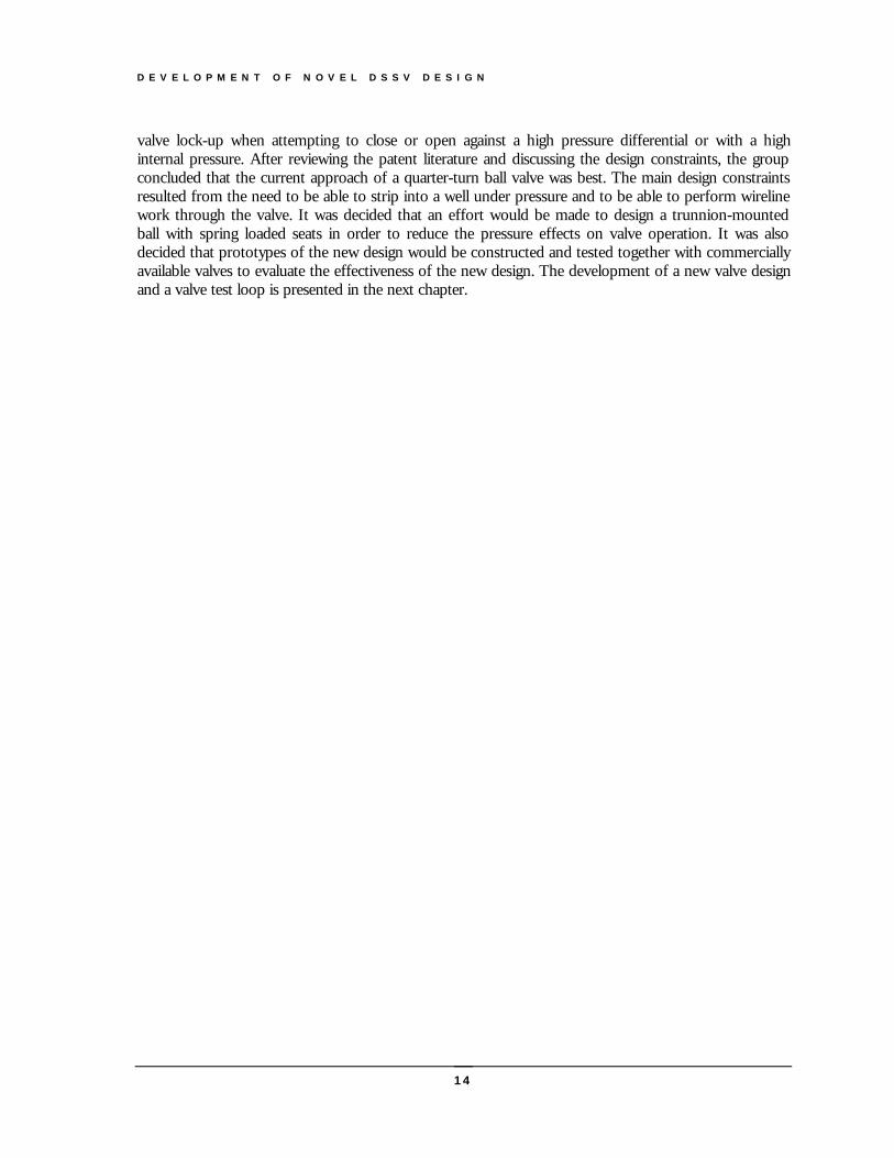
The drop-in or wireline retrievablecheck valve (Figure 12) overcomesmany of the objections to a float inthe drill collars. A sub that will accept
Figure 12: Schematic of a Drop-in / Wireline RetrievableCheck Valve
D E V E L O P M E N T O F N O V E L D S S V D E S I G N
13
Threads
Seat
Ball
Passage
Venturi
Figure 13: Schematic of a Velocity TriggeredTrip Valve
Figure 14: Schematic of a Double DSSV
a check valve is always run in the drill string nearbottom. Just before it becomes necessary to pullthe drillstring from the well, the check valveassembly is dropped into an open drillpipeconnection and pumped to bottom where itlatches into the sub. If the well tries to blowoutduring tripping operations, the check valve willstop the flow and make it easy to stab and closethe surface DSSV as part of the shut-inprocedure. In the event wireline work below thecheck valve becomes necessary, the drop-in checkvalve is wireline retrievable. However, the drop-incheck valve would not provide a barrier toblowouts when making a connection duringdrilling if it is not deployed until trippingoperations begin.
An example of a velocity triggered check valve isshown in Figure 13. This valve was designed andtested to a limited extent during the late 70’s byHughes Tool Company for Shell. It was lost inthe shuffle of buy-outs during the 80’s. Prototypevalves are again being built by a new company.
An example of a double valve assembly is shownin Figure 14. For high flow rates, the lower ballmay cut out, but the flow rate should be reducedenough to allow the upper valve to besuccessfully closed (if it is closed quickly beforethe bottom valve becomes too eroded). Thebottom valve can also be used as a mud savervalve since a back-up valve is available. Thedisadvantage of this approach is that it is not wellsuited to stabbing valves, because of the extraweight that must be handled. Even a singlestabbing valve for 4.5-in. or 5-in. drillpipe weighsmore than 100lbs. To minimize the weight of adouble valve, one manufacturer recentlydeveloped a double ball, single body design.
New Prototype DesignAn interdisciplinary team was assembled whichincluded seniors and supervising faculty in theLSU Petroleum Engineering and MechanicalEngineering Departments. The group wascharged with the development of an improvedDSSV design that would reduce the tendency for
D E V E L O P M E N T O F N O V E L D S S V D E S I G N
14
valve lock-up when attempting to close or open against a high pressure differential or with a highinternal pressure. After reviewing the patent literature and discussing the design constraints, the groupconcluded that the current approach of a quarter-turn ball valve was best. The main design constraintsresulted from the need to be able to strip into a well under pressure and to be able to perform wirelinework through the valve. It was decided that an effort would be made to design a trunnion-mountedball with spring loaded seats in order to reduce the pressure effects on valve operation. It was alsodecided that prototypes of the new design would be constructed and tested together with commerciallyavailable valves to evaluate the effectiveness of the new design. The development of a new valve designand a valve test loop is presented in the next chapter.
D E V E L O P M E N T O F N O V E L D S S V D E S I G N
15
Development of Novel DSSV Design
Drill String Safety Valves (DSSVs) are used to prevent blowouts through thedrillstring during tripping operations. Several case history reviews of well controlevents have shown evidence of severe problems with DSSVs. Of those problems, valvelock up is most significant resulting in failure to open or close due to high torque.
his Chapter describes the design and testing of a prototype low torque DSSV of the ball valve type. Theprototype design relies upon a trunnion-mounted ball and pseudo-fixed seats to achieve low torqueoperation, with the idealized design goal being a constant actuation torque independent of valve internalpressure. Development of the novel DSSV took place in Phase II and Phase III of the project. Phase IIincluded the design, construction, and testing of an initial prototype. In Phase III, the design was improved
based on the results of Phase II and finite element modeling of stresses in the bearing surfaces. Additional testing wasthen completed. Commercially available valves were tested with the new prototype to provide a basis for evaluation ofthe new ball and seat design concept.
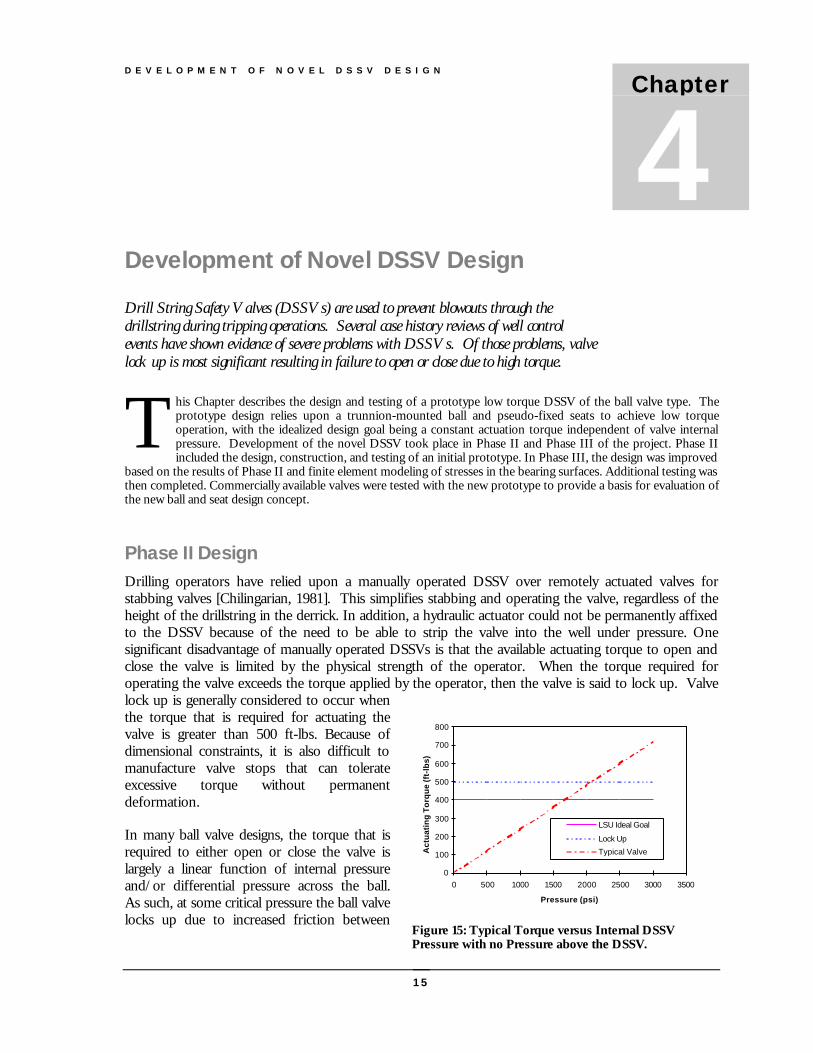
Phase II DesignDrilling operators have relied upon a manually operated DSSV over remotely actuated valves forstabbing valves [Chilingarian, 1981]. This simplifies stabbing and operating the valve, regardless of theheight of the drillstring in the derrick. In addition, a hydraulic actuator could not be permanently affixedto the DSSV because of the need to be able to strip the valve into the well under pressure. Onesignificant disadvantage of manually operated DSSVs is that the available actuating torque to open andclose the valve is limited by the physical strength of the operator. When the torque required foroperating the valve exceeds the torque applied by the operator, then the valve is said to lock up. Valvelock up is generally considered to occur whenthe torque that is required for actuating thevalve is greater than 500 ft-lbs. Because ofdimensional constraints, it is also difficult tomanufacture valve stops that can tolerateexcessive torque without permanentdeformation.
In many ball valve designs, the torque that isrequired to either open or close the valve islargely a linear function of internal pressureand/or differential pressure across the ball.As such, at some critical pressure the ball valvelocks up due to increased friction between
Chapter
4
T
0
100
200
300
400
500
600
700
800
0 500 1000 1500 2000 2500 3000 3500
Pressure (psi)
Act
uat
ing
To
rqu
e (f
t-lb
s)
LSU Ideal Goal
Lock Up
Typical Valve
Figure 15: Typical Torque versus Internal DSSVPressure with no Pressure above the DSSV.
D E V E L O P M E N T O F N O V E L D S S V D E S I G N
16
internal components. Figure 15 illustrates the problem of lock up for a typical manually actuated ballvalve. An ideal DSSV ball valve design is one where the required actuation torque is constant andindependent of the valve pressure, up to the maximum design sealing pressure. For such a valve, lockup will never occur as long as the constant required actuation torque is below the lock up torque value.Figure 15 also illustrates this idealized concept.
The objective of Phase I was to design, construct and test a DSSV with an actuation torque vs.differential pressure curve that approaches the idealized, constant torque design. This work focusesupon the low torque ability of the DSSV to open under large differential pressures and to close underhigh flow conditions. It considers low torque ability of the DSSV to close under equalized pressure as asecondary design criterion, as much less torque is required when the pressure above the DSSV is equalto the internal DSSV pressure.
Ball valve designs commonly employ either a trunnion-mounted ball with floating seats or a floating ballwith fixed seats [Piper, 1985]. In both cases, the pressure of the fluid being sealed generates the sealingforce between the ball and the seats. The seats are then said to be energized. Of course, due to thefriction between the ball and the seats, and under ideal conditions, the required actuation torque forthese designs increases linearly with this pressure. In order to achieve the design goal of an actuationtorque independent of differential pressure, the fluid being sealed cannot be used to energize the seats.One way of achieving thisperformance is to mount both theseats and the ball in the valve body.In this manner all forces which acton the ball and the seats are directlytransferred to the valve body. Sucha design then requires a separatemeans to energize the seats with aforce large enough to provideadequate sealing up to themaximum rated pressure. This isthe basis for the design resultingfrom this project.
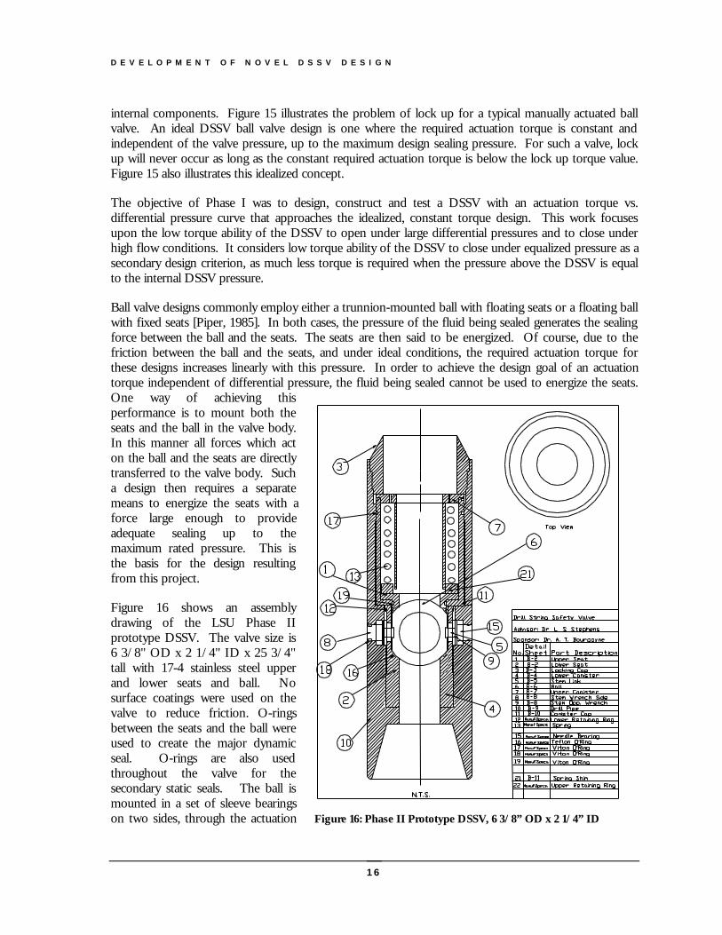
Figure 16 shows an assemblydrawing of the LSU Phase IIprototype DSSV. The valve size is6 3/8" OD x 2 1/4" ID x 25 3/4"tall with 17-4 stainless steel upperand lower seats and ball. Nosurface coatings were used on thevalve to reduce friction. O-ringsbetween the seats and the ball wereused to create the major dynamicseal. O-rings are also usedthroughout the valve for thesecondary static seals. The ball ismounted in a set of sleeve bearingson two sides, through the actuation Figure 16: Phase II Prototype DSSV, 6 3/8” OD x 2 1/4” ID
D E V E L O P M E N T O F N O V E L D S S V D E S I G N
17
stem and stem link. The tolerances between the ball, stem link, stem and bearings are kept small suchthat the ball can "float" only a few thousandths of an inch before engaging the sleeve bearings. Inessence the ball is trunnion mounted. Using this mounting, the pressure acting against the ball istransferred to the valve body through the bearings. The bearing load capacity is thus a limiting factorfor the valve design. Stresses are concentrated in the bearing bore rather than being distributed acrossthe ball and seat. Commercially available bearings were reviewed for this service and those with thegreatest load capacity for the given space constraint were selected. Even so, the bearing load capacitylimits the differential pressure capability of the valve to 4000 psi. This is only 80% of the target designspecification of a differential pressure of 5000 psi. It should also be noted that the torque required toactuate the valve must increase with differential pressure to the extent that the bearing frictional forceincreases. However, the pressure range was sufficient to allow testing of the new design concept.
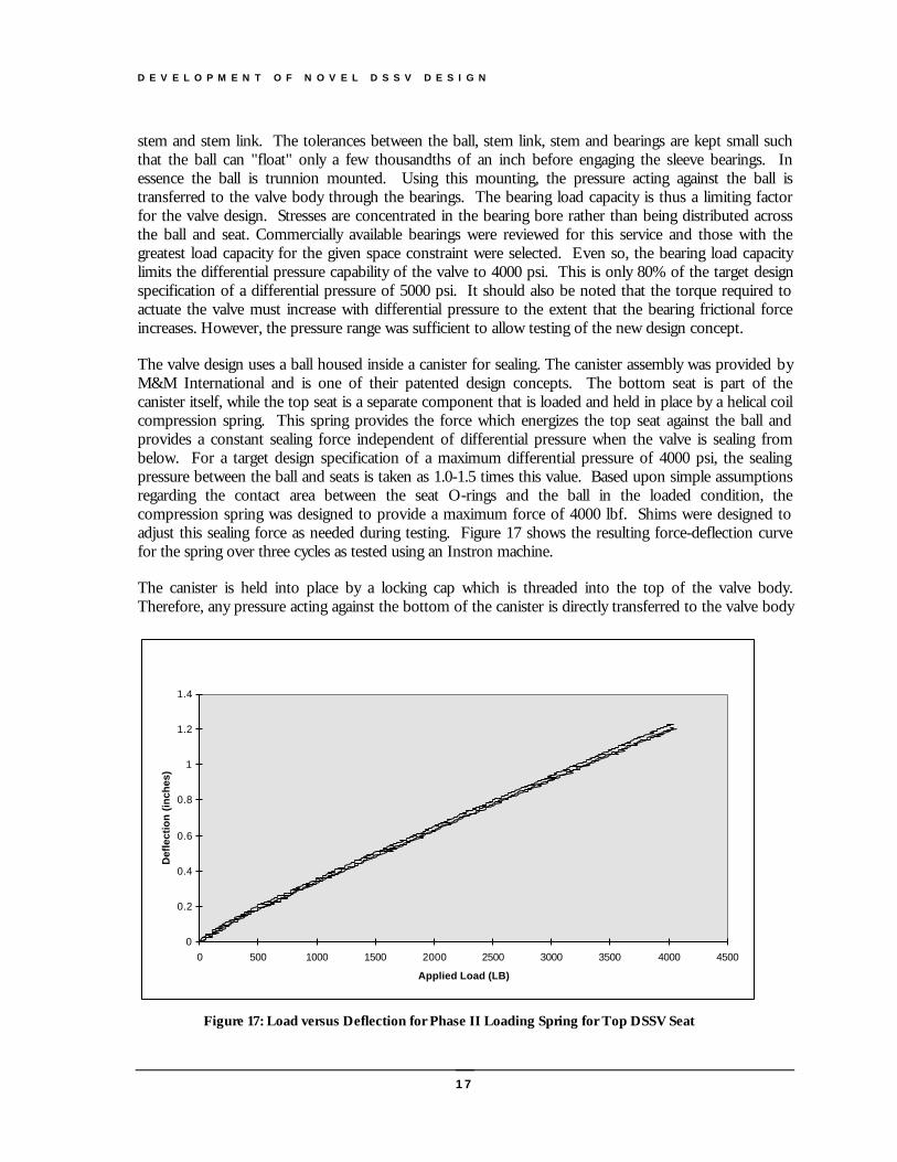
The valve design uses a ball housed inside a canister for sealing. The canister assembly was provided byM&M International and is one of their patented design concepts. The bottom seat is part of thecanister itself, while the top seat is a separate component that is loaded and held in place by a helical coilcompression spring. This spring provides the force which energizes the top seat against the ball andprovides a constant sealing force independent of differential pressure when the valve is sealing frombelow. For a target design specification of a maximum differential pressure of 4000 psi, the sealingpressure between the ball and seats is taken as 1.0-1.5 times this value. Based upon simple assumptionsregarding the contact area between the seat O-rings and the ball in the loaded condition, thecompression spring was designed to provide a maximum force of 4000 lbf. Shims were designed toadjust this sealing force as needed during testing. Figure 17 shows the resulting force-deflection curvefor the spring over three cycles as tested using an Instron machine.
The canister is held into place by a locking cap which is threaded into the top of the valve body.Therefore, any pressure acting against the bottom of the canister is directly transferred to the valve body
0
0.2
0.4
0.6
0.8
1
1.2
1.4
0 500 1000 1500 2000 2500 3000 3500 4000 4500
Applied Load (LB)
Def
lect
ion
(in
ches
)
Figure 17: Load versus Deflection for Phase II Loading Spring for Top DSSV Seat
D E V E L O P M E N T O F N O V E L D S S V D E S I G N
18
through the locking cap. Together, the bearings, canister, spring and locking cap provide a designwhere the differential pressure contribution to the actuation torque depends primarily upon the sleevebearing internal friction. Optimal selection of frictionless bearings then results in a low torque DSSVdesign when sealing a differential pressure from the below. Another limitation of the prototype designshown in Figure 16 is that when pressure is applied from above, the low torque operation is lost. Thisis not considered to be a significant limitation as the pressure when sealing from above can becontrolled by the operator. Finally, thrust bearings are mounted on the actuation stems to reduce thefriction between internal components due to the pressure difference between the interior and exterior ofthe valve. This design can be termed a trunnion-mounted ball, pseudo-fixed seat design. Table 1below summarizes the specification of the Phase II DSSV.
Table 1: Phase II Prototype Design - Trunnion Mounted Ball, Pseudo-Fixed Seats
Internal Component Material 17-4 Stainless SteelSealing Surface Viton O-rings
Max. Body Pressure 10,000 psiMax. Differential Pressure 4,000 psi (Sealing from Below)Low Torque Operation Sealing from Below OnlyPrimary Sealing Surface Top Seat, sealing from above and below
Phase II Static Test ResultsThree types of static pressure tests were performed on the prototype safety valve. These were ahydrostatic test on the valve body, a measurement of torque required to open under a differentialpressure, and a measurement of torque required to close under 100% equalized pressure. No testsunder flow conditions were conducted in this first series of tests. All tests were performed using water,pressurized by a hydraulic test stand at a local valve manufacturer’s facility. These tests were similar tothose performed by the commercial DSSV manufacturer. Torque readings were made by a calibrateddigital torque wrench. The hydrostatic pressure test required the valve body and stem seals to effectivelyseal twice the maximum allowable working pressure of the valve for 5 minutes. The valve exceededthis performance by sealing a pressure of 10,000 psi for a 15-minute period. Torque measurementsunder differential and 100% equalized pressure were obtained as part of the following testingprocedure:
1. Begin with valve in closed position;
2. Pressurize valve from below to the desired level;
3. Hold at this pressure for 5 minutes and check for evidence of leakage across the ball;
4. Open the valve using the torque wrench to obtain the torque required to open under differential pressure (The valve is now at 100% equalized pressure on both sides of the ball);
5. Close the valve using the torque wrench to obtain the torque required to close under 100% equalizedpressure.
D E V E L O P M E N T O F N O V E L D S S V D E S I G N
19
Torque to Open under Differential Pressure
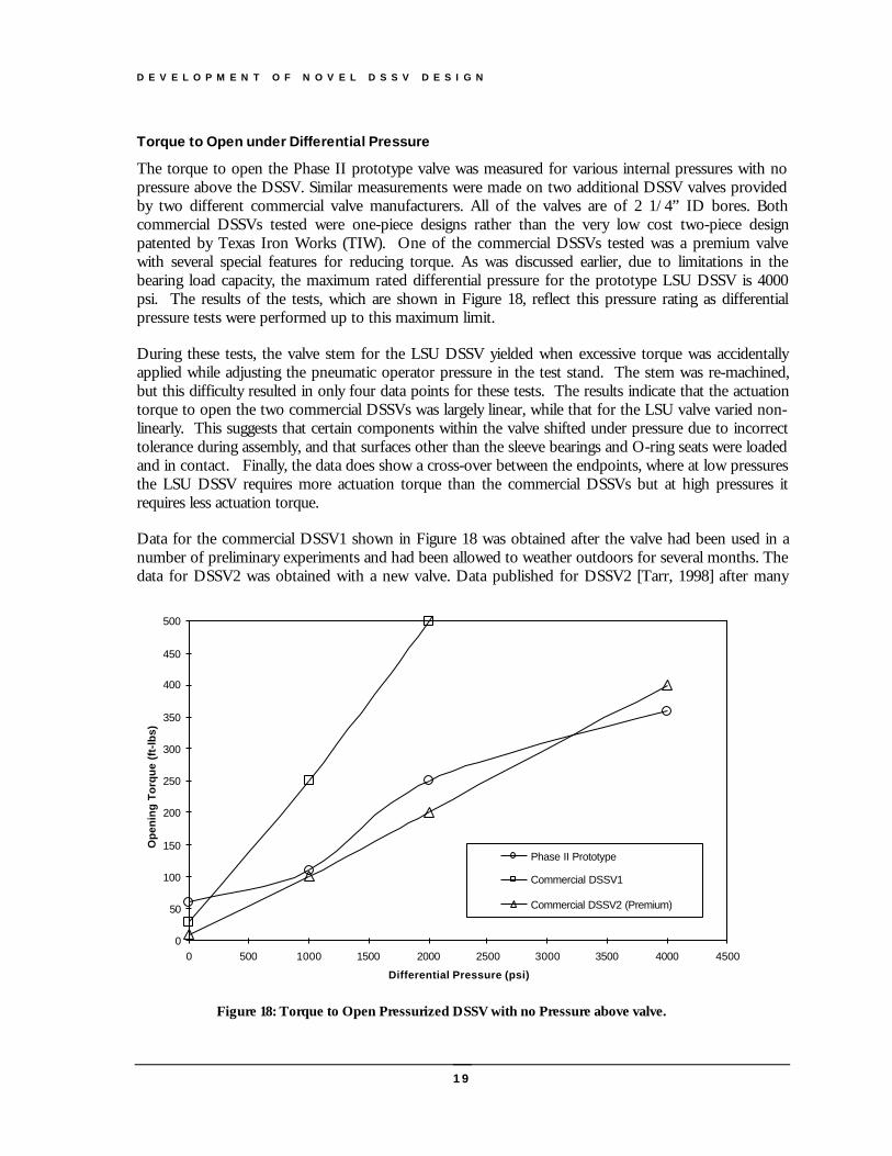
The torque to open the Phase II prototype valve was measured for various internal pressures with nopressure above the DSSV. Similar measurements were made on two additional DSSV valves providedby two different commercial valve manufacturers. All of the valves are of 2 1/4” ID bores. Bothcommercial DSSVs tested were one-piece designs rather than the very low cost two-piece designpatented by Texas Iron Works (TIW). One of the commercial DSSVs tested was a premium valvewith several special features for reducing torque. As was discussed earlier, due to limitations in thebearing load capacity, the maximum rated differential pressure for the prototype LSU DSSV is 4000psi. The results of the tests, which are shown in Figure 18, reflect this pressure rating as differentialpressure tests were performed up to this maximum limit.
During these tests, the valve stem for the LSU DSSV yielded when excessive torque was accidentallyapplied while adjusting the pneumatic operator pressure in the test stand. The stem was re-machined,but this difficulty resulted in only four data points for these tests. The results indicate that the actuationtorque to open the two commercial DSSVs was largely linear, while that for the LSU valve varied non-linearly. This suggests that certain components within the valve shifted under pressure due to incorrecttolerance during assembly, and that surfaces other than the sleeve bearings and O-ring seats were loadedand in contact. Finally, the data does show a cross-over between the endpoints, where at low pressuresthe LSU DSSV requires more actuation torque than the commercial DSSVs but at high pressures itrequires less actuation torque.
Data for the commercial DSSV1 shown in Figure 18 was obtained after the valve had been used in anumber of preliminary experiments and had been allowed to weather outdoors for several months. Thedata for DSSV2 was obtained with a new valve. Data published for DSSV2 [Tarr, 1998] after many
0
50
100
150
200
250
300
350
400
450
500
0 500 1000 1500 2000 2500 3000 3500 4000 4500
Differential Pressure (psi)
Op
enin
g T
orq
ue
(ft-
lbs)
Phase II Prototype
Commercial DSSV1
Commercial DSSV2 (Premium)
Figure 18: Torque to Open Pressurized DSSV with no Pressure above valve.
D E V E L O P M E N T O F N O V E L D S S V D E S I G N
20
cycles and after exposure to a water-base mud containing sand fell slightly above the data for DSSV1.Experience during the development of the testing program indicated that the operating torque forDSSVs under a differential pressure depended to a great extent upon the previous history of the valve.
Torque to Close DSSV under Equalized Pressure
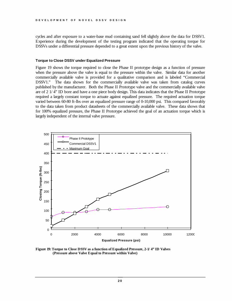
Figure 19 shows the torque required to close the Phase II prototype design as a function of pressurewhen the pressure above the valve is equal to the pressure within the valve. Similar data for anothercommercially available valve is provided for a qualitative comparison and is labeled “CommercialDSSV1.” The data shown for the commercially available valve was taken from catalog curvespublished by the manufacturer. Both the Phase II Prototype valve and the commercially available valveare of 2 1/4” ID bore and have a one piece body design. This data indicates that the Phase II Prototyperequired a largely constant torque to actuate against equalized pressure. The required actuation torquevaried between 60-80 ft-lbs over an equalized pressure range of 0-10,000 psi. This compared favorablyto the data taken from product datasheets of the commercially available valve. These data shows thatfor 100% equalized pressure, the Phase II Prototype achieved the goal of an actuation torque which islargely independent of the internal valve pressure.
0
50
100
150
200
250
300
350
400
450
500
0 2000 4000 6000 8000 10000 12000
Equalized Pressure (psi)
Clo
sin
g T
orq
ue
(ft-
lbs)
Phase II Prototype
Commercial DSSV1
Maximum Goal
Figure 19: Torque to Close DSSV as a function of Equalized Pressure, 2-1/4” ID Valves (Pressure above Valve Equal to Pressure within Valve)
D E V E L O P M E N T O F N O V E L D S S V D E S I G N
21
Post Test Valve Inspection
Upon completion of the testing, the valve was disassembled and inspected. Inspection revealedsignificant galling3 between the lower seat and the ball, between the ball and stem link, and between thestem link and stem. This wear indicates incorrect dimensional tolerance after assembly of the parts.Indeed, an assembly review revealed that the O-ring groove for the bottom seat was machined to thewrong size. The wear pattern between the ball and the stem link indicated that the ball was slightly offcenter. Finally, wear between the stem and the canister windows indicated that the bearing toleranceswere too loose and the canister acted as a bearing surface. Each of these deficiencies would beexpected to increase actuation torque for the ball valve as a function of differential pressure.
The results achieved with the Phase II prototype indicated that the basic design concept was valid andthe research team recommended that this design concept be kept for the Phase III design team. It wasalso recommended that additional analytical work be done to model stress and strain in the bearingassembly before doing the Phase III design work.
Finite Element Analysis of Bearing Bore
During the Phase II design of the valve, the bearing bore was identified as a key element to the successof the new design concept. The bearing bore was designed to fit into the outer shell or body of thevalve. The double stem bearing bore assembly must handle loads as high as 20,000 psi to achieve aDSSV with a 10,000 psi working pressure and a 2.25-in internal diameter. In terms of load handling,the bearing surface must be able to handle high loads with very little deflection. A Finite ElementAnalysis (FEA) was used to better understand how displacements and stresses on the bearing surface actunder certain load conditions. ANSYS 5.0, a commercial software package, was used to perform thefinite element analysis.
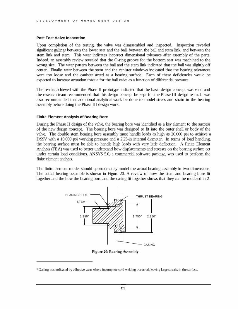
The finite element model should approximately model the actual bearing assembly in two dimensions.The actual bearing assemble is shown in Figure 20. A review of how the stem and bearing bore fittogether and the how the bearing bore and the casing fit together shows that they can be modeled in 2-
3 Galling was indicated by adhesive wear where incomplete cold welding occurred, leaving large streaks in the surface.
1.750"
CASING
1.250"
STEM
BEARING BORE
2.250"
THRUST BEARING
Figure 20: Bearing Assembly
D E V E L O P M E N T O F N O V E L D S S V D E S I G N
22
D as two concentric circles. The bearing was modeled as a “plane 82 2-D 8-node” structural-solid withthe key-option set to three in the ANSYS software package. What this means is that there are eightnodes with each having two degrees of freedom to move in the x and y coordinate directions. Thekey-option of three allows the model to be plane stress with a thickness to be input. The two sets of o-rings were left out of the model because they are used only as a seal surface and not a bearing surface.The model assumes that the valve body is rigid, allowing no deflection of the outer surface. The bearingmaterial was assumed to be homogeneous, having a modulus of elasticity of 30 Mpsi and a Poisson’sratio of 0.292. The compressive strength of the bearing material was 135,000 psi in an annealedcondition. The effect of a Melonite coating on the bearing surface was not included in the modelanalysis. Radial clearances of 0.001 to 0.003 inches were investigated.
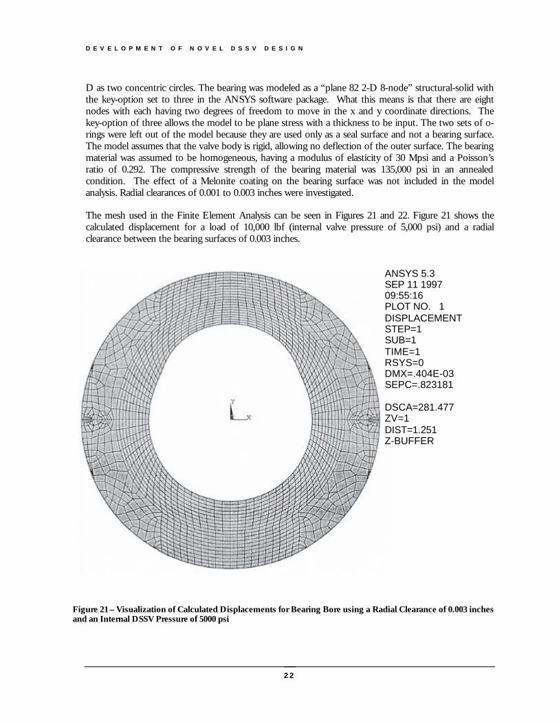
The mesh used in the Finite Element Analysis can be seen in Figures 21 and 22. Figure 21 shows thecalculated displacement for a load of 10,000 lbf (internal valve pressure of 5,000 psi) and a radialclearance between the bearing surfaces of 0.003 inches.
ANSYS 5.3SEP 11 199709:55:16PLOT NO. 1DISPLACEMENTSTEP=1SUB=1TIME=1RSYS=0DMX=.404E-03SEPC=.823181
DSCA=281.477ZV=1DIST=1.251Z-BUFFER
Figure 21 – Visualization of Calculated Displacements for Bearing Bore using a Radial Clearance of 0.003 inchesand an Internal DSSV Pressure of 5000 psi
D E V E L O P M E N T O F N O V E L D S S V D E S I G N
23
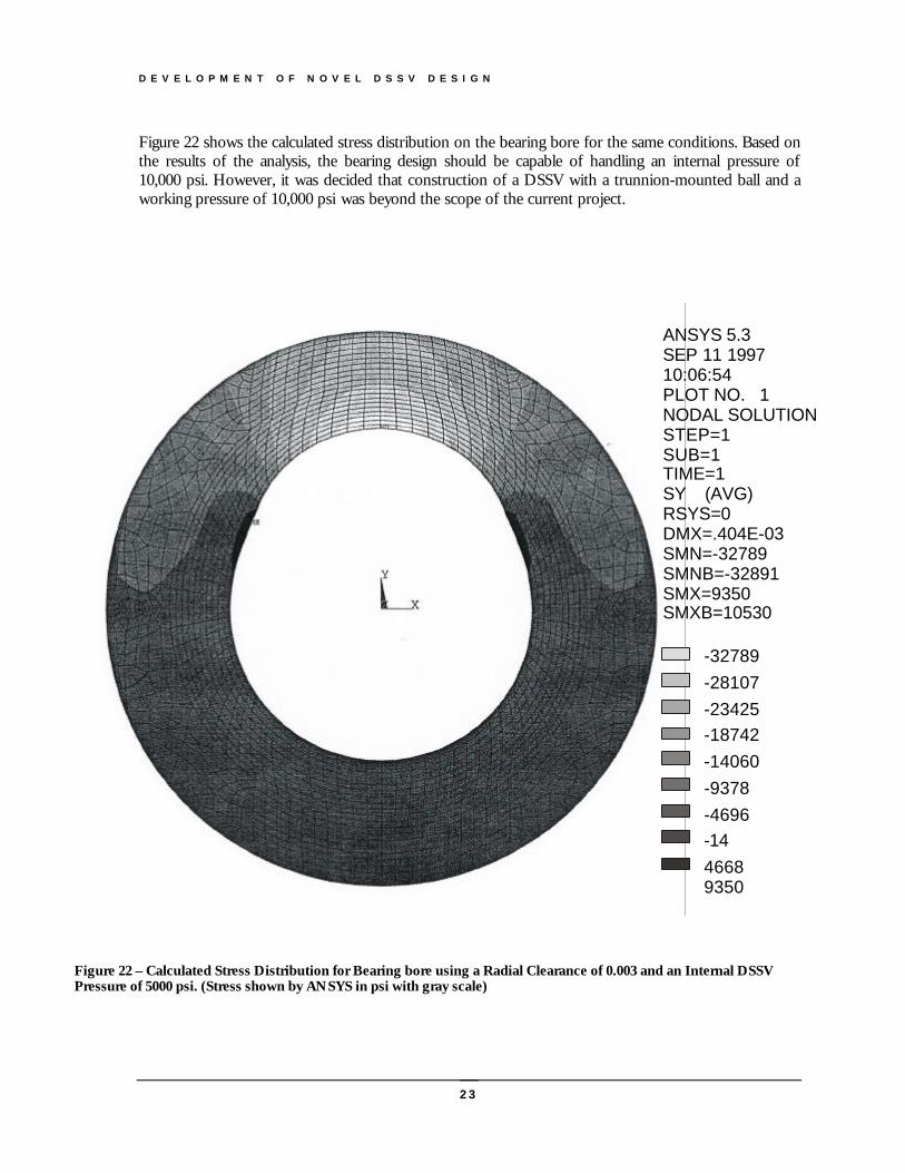
Figure 22 shows the calculated stress distribution on the bearing bore for the same conditions. Based onthe results of the analysis, the bearing design should be capable of handling an internal pressure of10,000 psi. However, it was decided that construction of a DSSV with a trunnion-mounted ball and aworking pressure of 10,000 psi was beyond the scope of the current project.
ANSYS 5.3SEP 11 199710:06:54PLOT NO. 1NODAL SOLUTIONSTEP=1SUB=1TIME=1SY (AVG)RSYS=0DMX=.404E-03SMN=-32789SMNB=-32891SMX=9350SMXB=10530
-32789-28107-23425-18742-14060-9378-4696-1446689350
Figure 22 – Calculated Stress Distribution for Bearing bore using a Radial Clearance of 0.003 and an Internal DSSVPressure of 5000 psi. (Stress shown by ANSYS in psi with gray scale)
D E V E L O P M E N T O F N O V E L D S S V D E S I G N
24
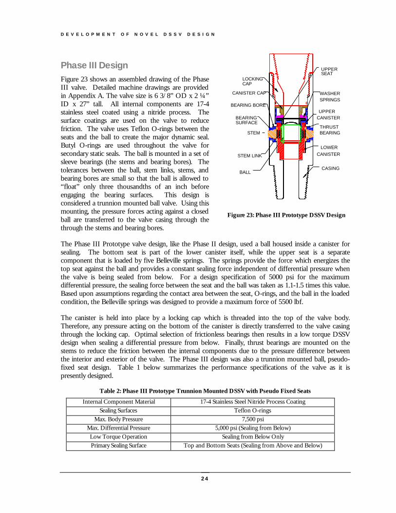
Phase III DesignFigure 23 shows an assembled drawing of the PhaseIII valve. Detailed machine drawings are providedin Appendix A. The valve size is 6 3/8” OD x 2 ¼”ID x 27” tall. All internal components are 17-4stainless steel coated using a nitride process. Thesurface coatings are used on the valve to reducefriction. The valve uses Teflon O-rings between theseats and the ball to create the major dynamic seal.Butyl O-rings are used throughout the valve forsecondary static seals. The ball is mounted in a set ofsleeve bearings (the stems and bearing bores). Thetolerances between the ball, stem links, stems, andbearing bores are small so that the ball is allowed to“float” only three thousandths of an inch beforeengaging the bearing surfaces. This design isconsidered a trunnion mounted ball valve. Using thismounting, the pressure forces acting against a closedball are transferred to the valve casing through thethrough the stems and bearing bores.
The Phase III Prototype valve design, like the Phase II design, used a ball housed inside a canister forsealing. The bottom seat is part of the lower canister itself, while the upper seat is a separatecomponent that is loaded by five Belleville springs. The springs provide the force which energizes thetop seat against the ball and provides a constant sealing force independent of differential pressure whenthe valve is being sealed from below. For a design specification of 5000 psi for the maximumdifferential pressure, the sealing force between the seat and the ball was taken as 1.1-1.5 times this value.Based upon assumptions regarding the contact area between the seat, O-rings, and the ball in the loadedcondition, the Belleville springs was designed to provide a maximum force of 5500 lbf.
The canister is held into place by a locking cap which is threaded into the top of the valve body.Therefore, any pressure acting on the bottom of the canister is directly transferred to the valve casingthrough the locking cap. Optimal selection of frictionless bearings then results in a low torque DSSVdesign when sealing a differential pressure from below. Finally, thrust bearings are mounted on thestems to reduce the friction between the internal components due to the pressure difference betweenthe interior and exterior of the valve. The Phase III design was also a trunnion mounted ball, pseudo-fixed seat design. Table 1 below summarizes the performance specifications of the valve as it ispresently designed.
Table 2: Phase III Prototype Trunnion Mounted DSSV with Pseudo Fixed Seats
Internal Component Material 17-4 Stainless Steel Nitride Process CoatingSealing Surfaces Teflon O-rings
Max. Body Pressure 7,500 psiMax. Differential Pressure 5,000 psi (Sealing from Below)Low Torque Operation Sealing from Below OnlyPrimary Sealing Surface Top and Bottom Seats (Sealing from Above and Below)
UPPERSEAT
BEARINGSURFACE
BEARING BORE
STEM LINK
BALL
LOCKINGCAP
CANISTER CAP
THRUST
CASING
LOWERCANISTER
WASHERSPRINGS
UPPERCANISTER
STEM BEARING
Figure 23: Phase III Prototype DSSV Design
D E V E L O P M E N T O F N O V E L D S S V D E S I G N
25
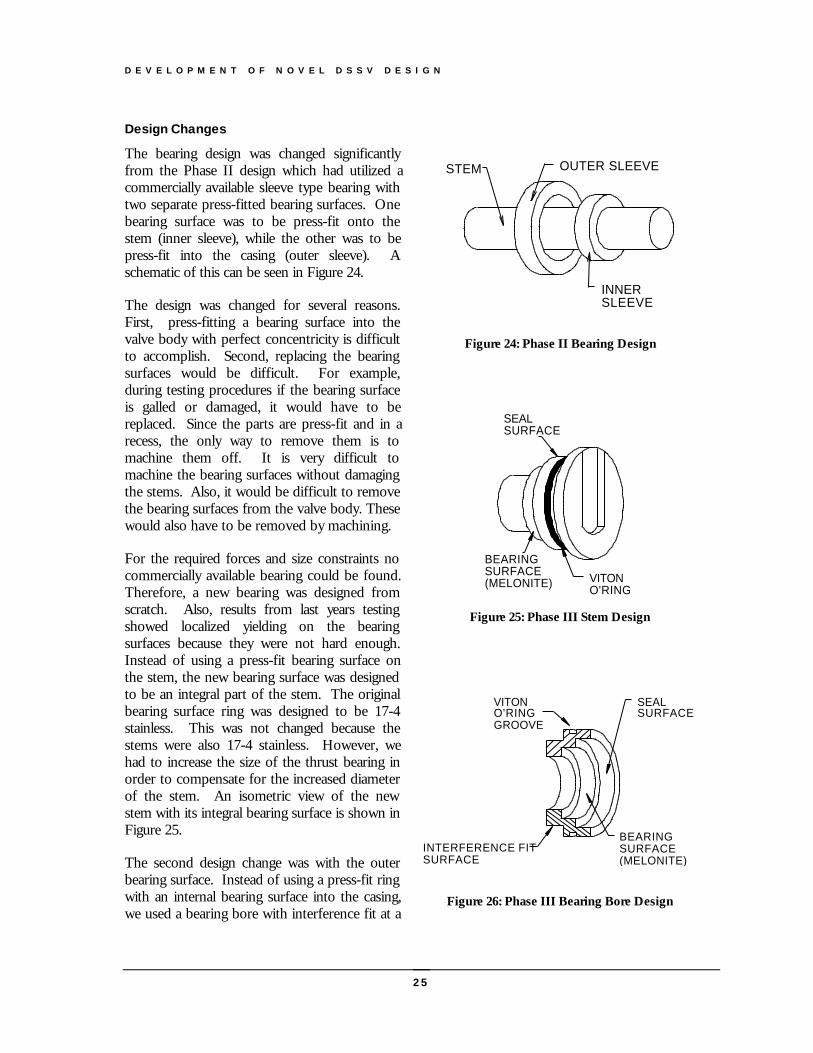
Design Changes
The bearing design was changed significantlyfrom the Phase II design which had utilized acommercially available sleeve type bearing withtwo separate press-fitted bearing surfaces. Onebearing surface was to be press-fit onto thestem (inner sleeve), while the other was to bepress-fit into the casing (outer sleeve). Aschematic of this can be seen in Figure 24.
The design was changed for several reasons.First, press-fitting a bearing surface into thevalve body with perfect concentricity is difficultto accomplish. Second, replacing the bearingsurfaces would be difficult. For example,during testing procedures if the bearing surfaceis galled or damaged, it would have to bereplaced. Since the parts are press-fit and in arecess, the only way to remove them is tomachine them off. It is very difficult tomachine the bearing surfaces without damagingthe stems. Also, it would be difficult to removethe bearing surfaces from the valve body. Thesewould also have to be removed by machining.
For the required forces and size constraints nocommercially available bearing could be found.Therefore, a new bearing was designed fromscratch. Also, results from last years testingshowed localized yielding on the bearingsurfaces because they were not hard enough.Instead of using a press-fit bearing surface onthe stem, the new bearing surface was designedto be an integral part of the stem. The originalbearing surface ring was designed to be 17-4stainless. This was not changed because thestems were also 17-4 stainless. However, wehad to increase the size of the thrust bearing inorder to compensate for the increased diameterof the stem. An isometric view of the newstem with its integral bearing surface is shown inFigure 25.
The second design change was with the outerbearing surface. Instead of using a press-fit ringwith an internal bearing surface into the casing,we used a bearing bore with interference fit at a
OUTER SLEEVE
INNERSLEEVE
STEM
Figure 24: Phase II Bearing Design
BEARINGSURFACE(MELONITE)
VITONO'RING
SEALSURFACE
Figure 25: Phase III Stem Design
INTERFERENCE FITSURFACE
SEALSURFACE
BEARINGSURFACE(MELONITE)
VITONO'RINGGROOVE
Figure 26: Phase III Bearing Bore Design
D E V E L O P M E N T O F N O V E L D S S V D E S I G N
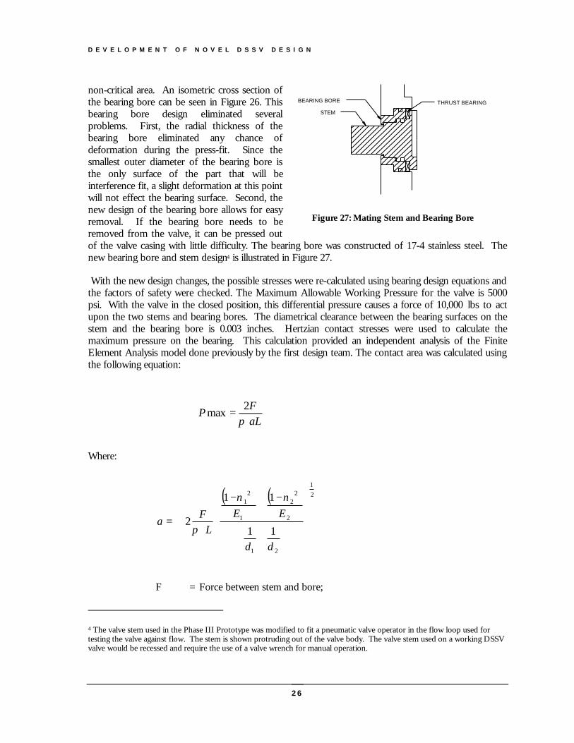
26
non-critical area. An isometric cross section ofthe bearing bore can be seen in Figure 26. Thisbearing bore design eliminated severalproblems. First, the radial thickness of thebearing bore eliminated any chance ofdeformation during the press-fit. Since thesmallest outer diameter of the bearing bore isthe only surface of the part that will beinterference fit, a slight deformation at this pointwill not effect the bearing surface. Second, thenew design of the bearing bore allows for easyremoval. If the bearing bore needs to beremoved from the valve, it can be pressed outof the valve casing with little difficulty. The bearing bore was constructed of 17-4 stainless steel. Thenew bearing bore and stem design4 is illustrated in Figure 27.
With the new design changes, the possible stresses were re-calculated using bearing design equations andthe factors of safety were checked. The Maximum Allowable Working Pressure for the valve is 5000psi. With the valve in the closed position, this differential pressure causes a force of 10,000 lbs to actupon the two stems and bearing bores. The diametrical clearance between the bearing surfaces on thestem and the bearing bore is 0.003 inches. Hertzian contact stresses were used to calculate themaximum pressure on the bearing. This calculation provided an independent analysis of the FiniteElement Analysis model done previously by the first design team. The contact area was calculated usingthe following equation:
Where:
F = Force between stem and bore;
4 The valve stem used in the Phase III Prototype was modified to fit a pneumatic valve operator in the flow loop used fortesting the valve against flow. The stem is shown protruding out of the valve body. The valve stem used on a working DSSVvalve would be recessed and require the use of a valve wrench for manual operation.
STEM
BEARING BORE THRUST BEARING
Figure 27: Mating Stem and Bearing Bore
( ) ( ) 21
21
2
22
1
21
11
11
2
+
−+
−
=
dd
EEL
Fa
νν
π
aLF
P 2
maxπ
=

D E V E L O P M E N T O F N O V E L D S S V D E S I G N
27
L = Length of bearing surface;
ν = Poisson’s Ratio;
E = Modulus of Elasticity;
d1 = Diameter of bearing surface on stem;
d2 = Diameter of bearing surface on bearing bore;
1 = Denotes stem material properties; and
2 = Denotes bearing bore material properties.
The static factor of safety was calculated by dividing the yield strength by the maximum pressure(Pmax). The factor of safety for a 5000 psi working pressure is 4.4. This is the ideal situation in whichonly the intended “bearing surface” is being used. For a 10,000 psi working pressure, the static factorof safety would be about 2.2.
There is a second scenario in which the factor of safety will change. The seal surfaces between thebearing bore and stem could come into contact when pressure is applied to the valve. This is becausethe required diametrical clearance between the sealing surfaces is only slightly above that of the bearingclearance (approximately 0.002”). In the case that the sealing surfaces and the bearing surface do comeinto contact, the contact area would increase thus causing the maximum pressure to decrease. Theworst case would be if the sealing surface absorbed all loads and the intended bearing surface absorbednone. This could happen if the tolerances between the stem bearing surface and the bearing bore werenot met. This case was also modeled using the equations given above. A factor of safety of 2.37 wascalculated for a working pressure of 5000 psi. For a working pressure of 10,000 psi, the factor ofsafety would be about 1.18.
Testing of Belleville Springs
The Belleville springs were used in the Phase III design to force the seat against the ball. The Bellevillewasher springs were designed to have an inside height of 0.080”, and a thickness of 0.150”, giving aheight over thickness ratio (the “h/t” ratio) of 0.533. This h/t ratio gives an approximately linearresponse when deflection is plotted against force. The springs as received from the manufacturer
differed from the original design. The receivedinside height was 0.070” and the thickness is0.105”. The h/t ratio is 0.667 and thecalculated spring response is less linear. Theforce of the received springs was computed tobe 1115 lbf at 0.065” of deflection. Five springsshould produce a force of 5575 lbf at the0.065” of deflection specified in the design.
To check the computed spring values, the asbuilt springs were tested in an Instroncompression tester. First, each spring was testedindividually to determine the individual springconstants. The springs were loaded betweenflat steel plates. Second, a stack of five springs
Spring Constant = 61098.46
lbs/in
y = 118673x2 + 74983x - 343.23
0
1000
2000
3000
4000
5000
6000
0 0.02 0.04 0.06 0.08
Deflection (in)
Lo
ad (
lbs)
Figure 28: Load versus Deflection for the stack of FiveSprings used in Phase III Prototype DSSV
D E V E L O P M E N T O F N O V E L D S S V D E S I G N
28
was tested. This test was done to verify that (1) the actual spring load was near the computed springload and (2) that the total load could be computed using the sum of the individual spring constants andthe same deflection for all five springs. The results of the tests showed that a force of 5032 lbf wouldbe generated for the stack of five springs used in the Phase III Prototype. Shown in Figure 28 are thetest results.
Assembly Procedure
The Drill String Safety Valve consists of many different integratingparts. Therefore, assembling the parts in the correct order is a must.The following is the procedure that was used to assemble the valve.
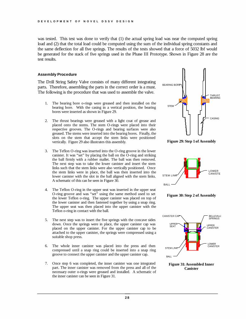
1. The bearing bore o-rings were greased and then installed on thebearing bore. With the casing in a vertical position, the bearingbores were inserted as shown in Figure 29.
2. The thrust bearings were greased with a light coat of grease andplaced onto the stems. The stem O-rings were placed into theirrespective grooves. The O-rings and bearing surfaces were alsogreased. The stems were inserted into the bearing bores. Finally, theslots on the stem that accept the stem links were positionedvertically. Figure 29 also illustrates this assembly.
3. The Teflon O-ring was inserted into the O-ring groove in the lowercanister. It was “set” by placing the ball on the O-ring and strikingthe ball firmly with a rubber mallet. The ball was then removed.The next step was to take the lower canister and insert the stemlinks such that the stem links were also vertically positioned. Oncethe stem links were in place, the ball was then inserted into thelower canister with the slot in the ball aligned with the stem links.A schematic of this can be seen in Figure 30.
4. The Teflon O-ring in the upper seat was inserted in the upper seatO-ring groove and was “set” using the same method used to setthe lower Teflon o-ring. The upper canister was placed on top ofthe lower canister and then fastened together by using a snap ring.The upper seat was then placed into the upper canister with theTeflon o-ring in contact with the ball.
5. The next step was to insert the five springs with the concave sidesdown. Once the springs were in place, the upper canister cap wasplaced on the upper canister. For the upper canister cap to beattached to the upper canister, the springs were compressed using asuitable shop press.
6. The whole inner canister was placed into the press and thencompressed until a snap ring could be inserted into a snap ringgroove to connect the upper canister and the upper canister cap.
7. Once step 6 was completed, the inner canister was one integratedpart. The inner canister was removed from the press and all of thenecessary outer o-rings were greased and installed. A schematic ofthe inner canister can be seen in Figure 31.
BEARING BORE
STEM
THRUST BEARING
CASING
Figure 29: Step 1 of Assembly
STEM LINK
BALL
LOWERCANISTER
Figure 30: Step 2 of Assembly
BELLEVILLE SPRINGS
STEM LINK
BALL
CANISTER CAP
UPPERSEAT
LOWERCANISTER
UPPERCANISTER
Figure 31: Assembled InnerCanister
D E V E L O P M E N T O F N O V E L D S S V D E S I G N
29
8. The final step was to insert the inner canister into the valve body. Once the inner canister was situatedproperly in the casing, the upper casing cap with its attached and greased o-ring was screwed on and theassembly was thus completed.
Phase III DSSV Test Program
The initial test conducted on the Phase III Prototype were hydrostatic tests conducted at a commercialvalve manufacturing facility. The test was similar to the test performed after manufacturer of acommercial valve. This test began with the water-filled valve in the closed position and one end of thevalve fitted with a threaded cap. The threaded cap was ported to allow hydrostatic pressure to beapplied. A high-pressure pump was used to increase the internal pressure of half of the valve. To passthe test, the pressure must be held for ten minutes with no significant leaks or drops in pressure. Theopposite end of the valve is then tested in a similar manner. The Phase III Prototype was testedsuccessfully in this manner to 7500 psi, which was 1.50 times working pressure of the valve. The DSSVwas then removed from the test apparatus and actuated to ensure no deformation occurred with themoving parts of the valve. Finally, the valve was disassembled and inspected for internal damage ordeformation of internal components.
The second type of tests conducted on the Phase III Prototype was a measurement of the torque tooperate the valve with internal pressure. For these tests, the pressure above the ball and upper seat wasequal to the internal pressure so that there was no pressure differential across the ball and seat. Thesetests were conducted at the LSU Research Well Facility operated by the Department of PetroleumEngineering. Similar tests were also performed on two commercially available DSSVs using the LSUfacility. Additional test results of this type had been reported in the literature for other valves. Thisallowed the performance of the Phase III prototype to be compared to several other valve designs.
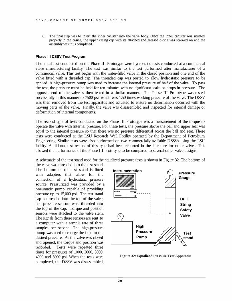
A schematic of the test stand used for the equalized pressure tests is shown in Figure 32. The bottom ofthe valve was threaded into the test stand.The bottom of the test stand is fittedwith adapters that allow for theconnection of a hydrostatic pressuresource. Pressurized was provided by apneumatic pump capable of providingpressure up to 15,000 psi. The test standcap is threaded into the top of the valve,and pressure sensors were threaded intothe top of the cap. Torque and positionsensors were attached to the valve stem.The signals from these sensors are sent toa computer with a sample rate of threesamples per second. The high-pressurepump was used to charge the fluid to thedesired pressure. As the valve was closedand opened, the torque and position wasrecorded. Tests were repeated threetimes for pressures of 1000, 2000, 3000,4000 and 5000 psi. When the tests werecompleted, the DSSV was disassembled,
HighPressurePump
Instrumentation PressureGauge
Teststand
DrillStringSafetyValve
Figure 32: Equalized Pressure Test Apparatus
D E V E L O P M E N T O F N O V E L D S S V D E S I G N
30
and the internal components were again inspected for damage and deformation. The test data ispresented and compared graphically to other DSSVs in the next section of this report
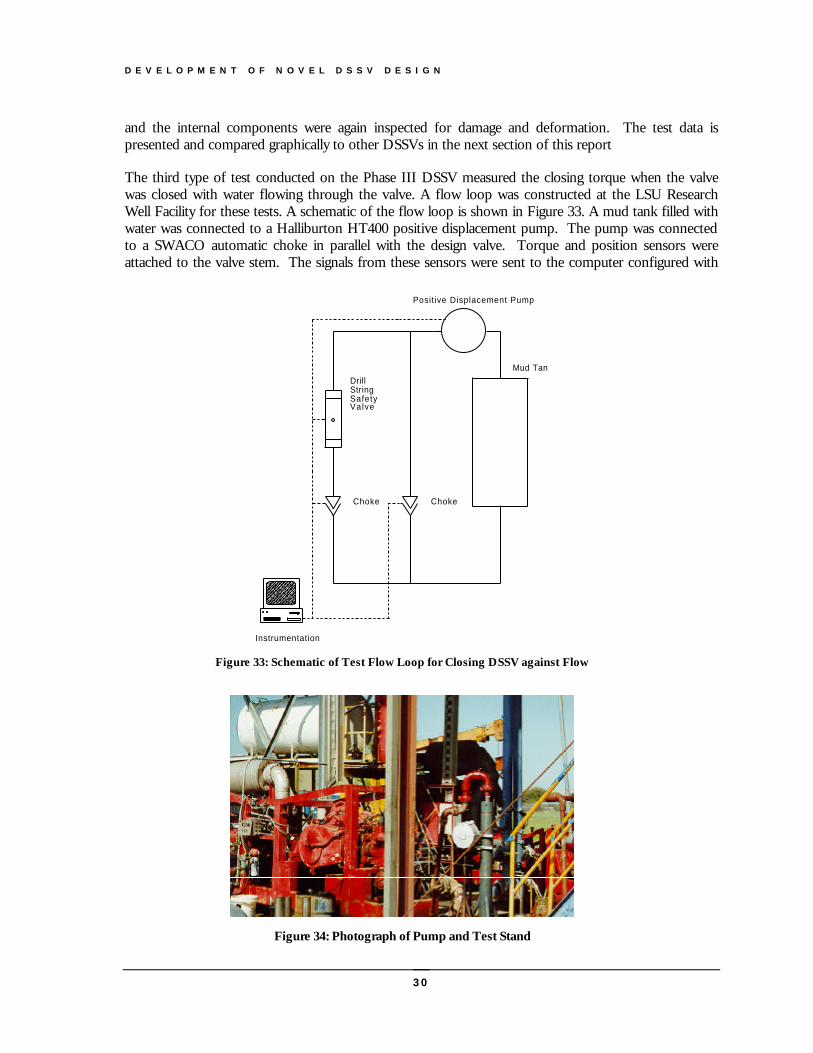
The third type of test conducted on the Phase III DSSV measured the closing torque when the valvewas closed with water flowing through the valve. A flow loop was constructed at the LSU ResearchWell Facility for these tests. A schematic of the flow loop is shown in Figure 33. A mud tank filled withwater was connected to a Halliburton HT400 positive displacement pump. The pump was connectedto a SWACO automatic choke in parallel with the design valve. Torque and position sensors wereattached to the valve stem. The signals from these sensors were sent to the computer configured with
Choke
Instrumentation
Choke
DrillStringSafetyValve
Positive Displacement Pump
Mud Tank
Figure 33: Schematic of Test Flow Loop for Closing DSSV against Flow
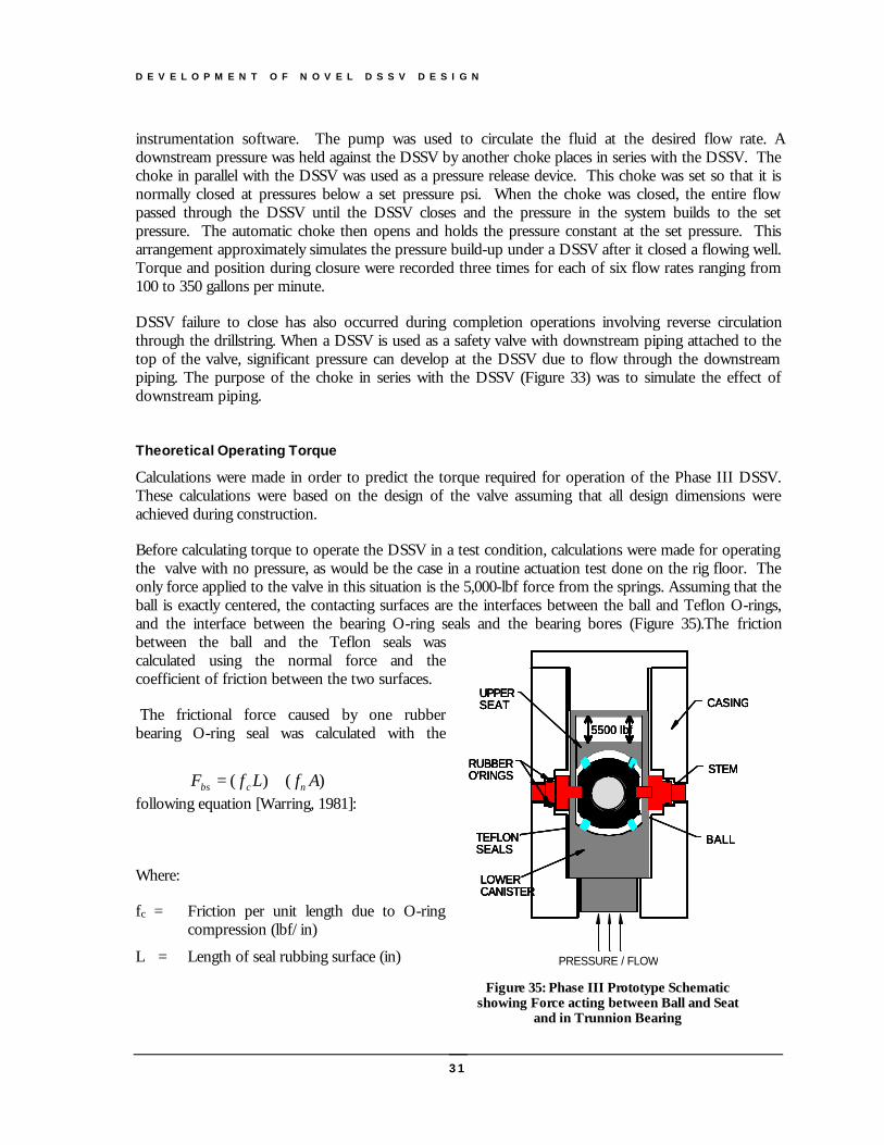
Figure 34: Photograph of Pump and Test Stand
D E V E L O P M E N T O F N O V E L D S S V D E S I G N
31
instrumentation software. The pump was used to circulate the fluid at the desired flow rate. Adownstream pressure was held against the DSSV by another choke places in series with the DSSV. Thechoke in parallel with the DSSV was used as a pressure release device. This choke was set so that it isnormally closed at pressures below a set pressure psi. When the choke was closed, the entire flowpassed through the DSSV until the DSSV closes and the pressure in the system builds to the setpressure. The automatic choke then opens and holds the pressure constant at the set pressure. Thisarrangement approximately simulates the pressure build-up under a DSSV after it closed a flowing well.Torque and position during closure were recorded three times for each of six flow rates ranging from100 to 350 gallons per minute.
DSSV failure to close has also occurred during completion operations involving reverse circulationthrough the drillstring. When a DSSV is used as a safety valve with downstream piping attached to thetop of the valve, significant pressure can develop at the DSSV due to flow through the downstreampiping. The purpose of the choke in series with the DSSV (Figure 33) was to simulate the effect ofdownstream piping.
Theoretical Operating Torque
Calculations were made in order to predict the torque required for operation of the Phase III DSSV.These calculations were based on the design of the valve assuming that all design dimensions wereachieved during construction.
Before calculating torque to operate the DSSV in a test condition, calculations were made for operatingthe valve with no pressure, as would be the case in a routine actuation test done on the rig floor. Theonly force applied to the valve in this situation is the 5,000-lbf force from the springs. Assuming that theball is exactly centered, the contacting surfaces are the interfaces between the ball and Teflon O-rings,and the interface between the bearing O-ring seals and the bearing bores (Figure 35).The frictionbetween the ball and the Teflon seals wascalculated using the normal force and thecoefficient of friction between the two surfaces.
The frictional force caused by one rubberbearing O-ring seal was calculated with the
following equation [Warring, 1981]:
Where:
fc = Friction per unit length due to O-ringcompression (lbf/in)
L = Length of seal rubbing surface (in)
BALLBALLBALLBALL
STEMSTEMSTEMSTEM
CASINGCASINGCASINGCASING
TEFLONSEALSTEFLONSEALSTEFLONSEALSTEFLONSEALS
PRESSURE / FLOW
LOWERCANISTERLOWERCANISTERLOWERCANISTERLOWERCANISTER
5500 lbf5500 lbf5500 lbf5500 lbf
UPPERSEATUPPERSEATUPPERSEATUPPERSEAT
RUBBERO'RINGSRUBBERO'RINGSRUBBERO'RINGSRUBBERO'RINGS
Figure 35: Phase III Prototype Schematicshowing Force acting between Ball and Seat
and in Trunnion Bearing
)()( AfLfF ncbs +=
D E V E L O P M E N T O F N O V E L D S S V D E S I G N
32
fn = Friction per unit area due to fluidpressure (lbf/in2)
A = Projected area of seal (in2)
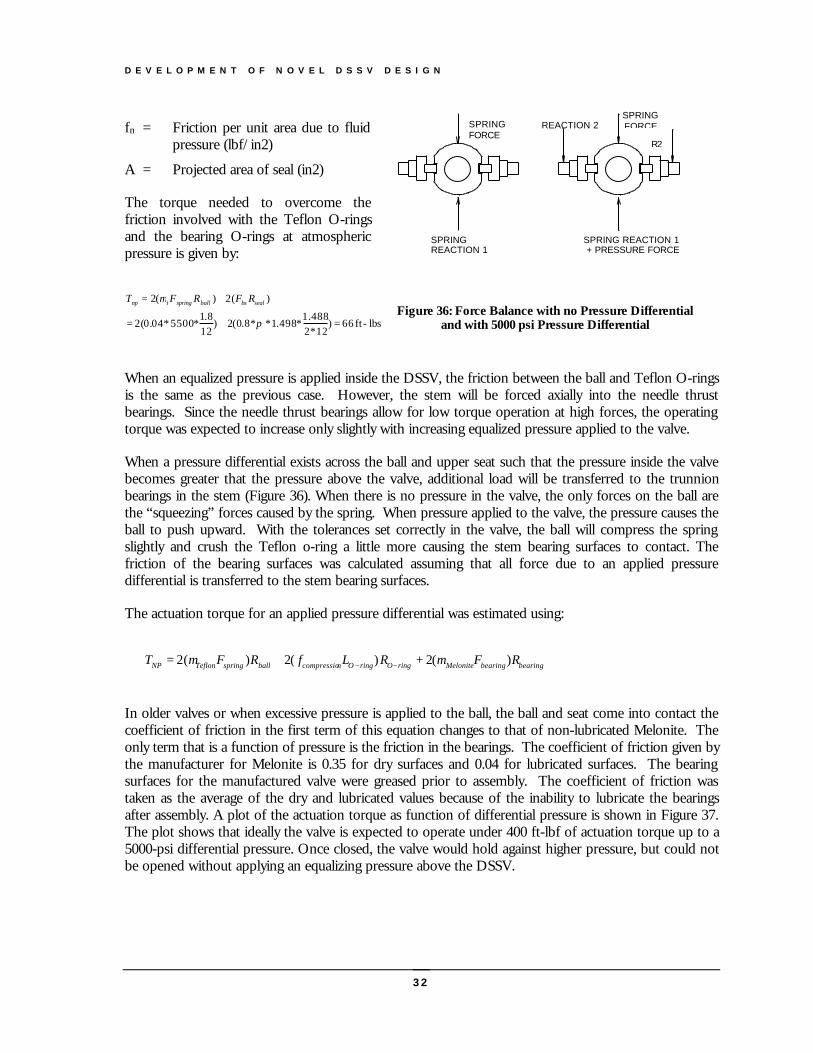
The torque needed to overcome thefriction involved with the Teflon O-ringsand the bearing O-rings at atmosphericpressure is given by:
When an equalized pressure is applied inside the DSSV, the friction between the ball and Teflon O-ringsis the same as the previous case. However, the stem will be forced axially into the needle thrustbearings. Since the needle thrust bearings allow for low torque operation at high forces, the operatingtorque was expected to increase only slightly with increasing equalized pressure applied to the valve.
When a pressure differential exists across the ball and upper seat such that the pressure inside the valvebecomes greater that the pressure above the valve, additional load will be transferred to the trunnionbearings in the stem (Figure 36). When there is no pressure in the valve, the only forces on the ball arethe “squeezing” forces caused by the spring. When pressure applied to the valve, the pressure causes theball to push upward. With the tolerances set correctly in the valve, the ball will compress the springslightly and crush the Teflon o-ring a little more causing the stem bearing surfaces to contact. Thefriction of the bearing surfaces was calculated assuming that all force due to an applied pressuredifferential is transferred to the stem bearing surfaces.
The actuation torque for an applied pressure differential was estimated using:
In older valves or when excessive pressure is applied to the ball, the ball and seat come into contact thecoefficient of friction in the first term of this equation changes to that of non-lubricated Melonite. Theonly term that is a function of pressure is the friction in the bearings. The coefficient of friction given bythe manufacturer for Melonite is 0.35 for dry surfaces and 0.04 for lubricated surfaces. The bearingsurfaces for the manufactured valve were greased prior to assembly. The coefficient of friction wastaken as the average of the dry and lubricated values because of the inability to lubricate the bearingsafter assembly. A plot of the actuation torque as function of differential pressure is shown in Figure 37.The plot shows that ideally the valve is expected to operate under 400 ft-lbf of actuation torque up to a5000-psi differential pressure. Once closed, the valve would hold against higher pressure, but could notbe opened without applying an equalizing pressure above the DSSV.
lbs-ft 66)12*2
488.1*498.1**8.0(2)
128.1
*5500*04.0(2
)(2)(2
=+=
+=
π
µ sealbsballspringtnp RFRFT
SPRINGREACTION 1
SPRINGFORCE
REACTION 2
R2
SPRING REACTION 1 + PRESSURE FORCE
SPRING FORCE
Figure 36: Force Balance with no Pressure Differentialand with 5000 psi Pressure Differential
bearingbearingMeloniteringOringOncompressioballspringTeflonNP RFRLfRFT )(2+)(2)(2 µµ −−+=
D E V E L O P M E N T O F N O V E L D S S V D E S I G N
33
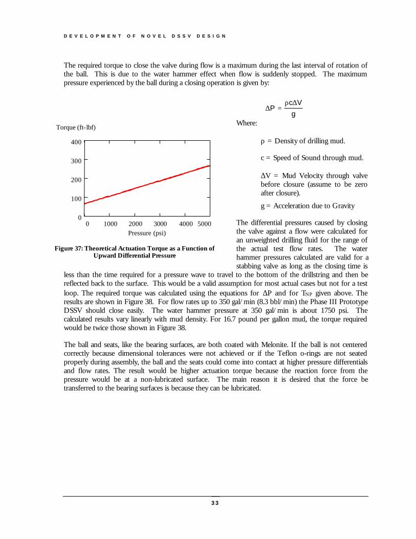
The required torque to close the valve during flow is a maximum during the last interval of rotation ofthe ball. This is due to the water hammer effect when flow is suddenly stopped. The maximumpressure experienced by the ball during a closing operation is given by:
Where:
ρ = Density of drilling mud.
c = Speed of Sound through mud.
∆V = Mud Velocity through valvebefore closure (assume to be zeroafter closure).
g = Acceleration due to Gravity
The differential pressures caused by closingthe valve against a flow were calculated foran unweighted drilling fluid for the range ofthe actual test flow rates. The waterhammer pressures calculated are valid for astabbing valve as long as the closing time is
less than the time required for a pressure wave to travel to the bottom of the drillstring and then bereflected back to the surface. This would be a valid assumption for most actual cases but not for a testloop. The required torque was calculated using the equations for ∆P and for TNP given above. Theresults are shown in Figure 38. For flow rates up to 350 gal/min (8.3 bbl/min) the Phase III PrototypeDSSV should close easily. The water hammer pressure at 350 gal/min is about 1750 psi. Thecalculated results vary linearly with mud density. For 16.7 pound per gallon mud, the torque requiredwould be twice those shown in Figure 38.
The ball and seats, like the bearing surfaces, are both coated with Melonite. If the ball is not centeredcorrectly because dimensional tolerances were not achieved or if the Teflon o-rings are not seatedproperly during assembly, the ball and the seats could come into contact at higher pressure differentialsand flow rates. The result would be higher actuation torque because the reaction force from thepressure would be at a non-lubricated surface. The main reason it is desired that the force betransferred to the bearing surfaces is because they can be lubricated.
0 1000 2000 3000 4000 50000
100
200
300
400
Pressure (psi)
Torque (ft-lbf)
Figure 37: Theoretical Actuation Torque as a Function ofUpward Differential Pressure
∆∆
Pc V
g=
ρ
D E V E L O P M E N T O F N O V E L D S S V D E S I G N
34
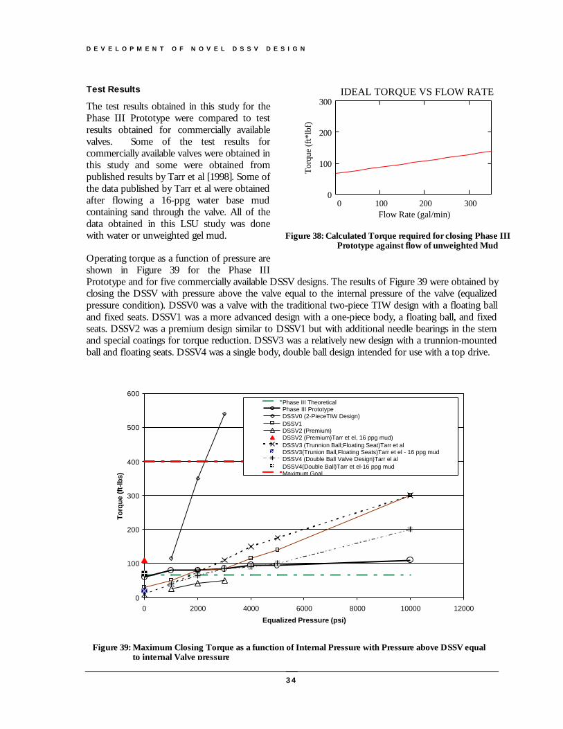
Test Results
The test results obtained in this study for thePhase III Prototype were compared to testresults obtained for commercially availablevalves. Some of the test results forcommercially available valves were obtained inthis study and some were obtained frompublished results by Tarr et al [1998]. Some ofthe data published by Tarr et al were obtainedafter flowing a 16-ppg water base mudcontaining sand through the valve. All of thedata obtained in this LSU study was donewith water or unweighted gel mud.
Operating torque as a function of pressure areshown in Figure 39 for the Phase IIIPrototype and for five commercially available DSSV designs. The results of Figure 39 were obtained byclosing the DSSV with pressure above the valve equal to the internal pressure of the valve (equalizedpressure condition). DSSV0 was a valve with the traditional two-piece TIW design with a floating balland fixed seats. DSSV1 was a more advanced design with a one-piece body, a floating ball, and fixedseats. DSSV2 was a premium design similar to DSSV1 but with additional needle bearings in the stemand special coatings for torque reduction. DSSV3 was a relatively new design with a trunnion-mountedball and floating seats. DSSV4 was a single body, double ball design intended for use with a top drive.
0 100 200 3000
100
200
300IDEAL TORQUE VS FLOW RATE
Flow Rate (gal/min)
Torq
ue (f
t*lb
f)
Figure 38: Calculated Torque required for closing Phase IIIPrototype against flow of unweighted Mud
0
100
200
300
400
500
600
0 2000 4000 6000 8000 10000 12000
Equalized Pressure (psi)
Torq
ue (f
t-lb
s)
Phase III TheoreticalPhase III PrototypeDSSV0 (2-PieceTIW Design)DSSV1DSSV2 (Premium)DSSV2 (Premium)Tarr et el, 16 ppg mud)DSSV3 (Trunnion Ball;Floating Seat)Tarr et alDSSV3(Trunion Ball,Floating Seats)Tarr et el - 16 ppg mudDSSV4 (Double Ball Valve Design)Tarr el alDSSV4(Double Ball)Tarr et el-16 ppg mudMaximum Goal
Figure 39: Maximum Closing Torque as a function of Internal Pressure with Pressure above DSSV equalto internal Valve pressure

D E V E L O P M E N T O F N O V E L D S S V D E S I G N
35
Note that the operating torque for the Phase III Prototype was much less sensitive to pressure than thecommercially available valves tested. At high pressures, the Phase III Prototype could be operated atmuch lower values of torque than the commercially available valves. At low internal pressures, the PhaseIII Prototype required a higher torque to close the valve than the commercially available valves. This wasan expected effect of the high spring force squeezing the upper seat against the ball. There was goodagreement between the calculated theoretical torque to close the valve and the measured torque to closethe valve for internal pressures below 1000 psi. However, at high values of internal pressure themeasured torque value were about 30% higher than the calculated theoretical values. It is believed thatthe reason for this discrepancy was because not all of the pressure loading was being transferred to thestem bearings as was assumed in the theoretical analysis. Compression of the spring with increasedpressure likely increased the friction between the ball and the seat, which was not considered in thetheoretical analysis. A more complex finite-element analysis, that was beyond the scope of this project,would be needed to consider these effects.
The maximum torque to open the Phase III DSSV with pressure inside the valve and atmosphericpressure above the closed ball and seat are shown in Figure 40. Note that in this test, the Phase IIIPrototype achieved the best results at the highest differential pressures used in the tests. DSSV2(Premium one-piece design) was a close second at 4000 psi and gave slightly better results than thePhase III Prototype at the lower differential pressures used in the tests. However, data taken in sandymud and reported by Tarr et al [1998] showed a much poorer performance for DSSV2. Although notsubjected to the sandy mud test protocol, the Phase III design would be expected to perform betterbecause the ball and seat are held in firm contact. Thus, solids cannot pass between the ball and seat andenter the valve body. Note that most DSSVs should not be expected to open with less than 400 ft-lbfof torque at differential pressures above about 1000 psi.
0
100
200
300
400
500
600
0 1000 2000 3000 4000 5000
Pressure Differential across Valve (psi)
To
rqu
e (f
t-lb
s)
Phase III Theoretical
Phase III Prototype
DSSV1
DSSV2 (Premium)
DSSV2 (Premium) Tarr et al - 16 ppg mud
DSSV3 (Trunnion Ball, Floating Seats) Tarr et al - Water
DSSV3 (Trunnion Ball, Floating Seats) Tarr et al - 16 ppg mud
Maximum Goal
Figure 40: Maximum Torque to Open DSSV as a function of Internal Pressure with AtmosphericPressure above DSSV
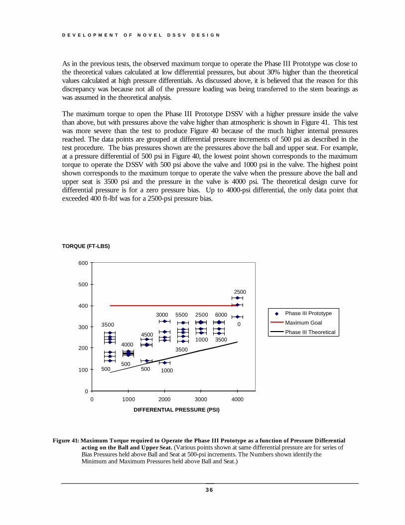
D E V E L O P M E N T O F N O V E L D S S V D E S I G N
36
As in the previous tests, the observed maximum torque to operate the Phase III Prototype was close tothe theoretical values calculated at low differential pressures, but about 30% higher than the theoreticalvalues calculated at high pressure differentials. As discussed above, it is believed that the reason for thisdiscrepancy was because not all of the pressure loading was being transferred to the stem bearings aswas assumed in the theoretical analysis.
The maximum torque to open the Phase III Prototype DSSV with a higher pressure inside the valvethan above, but with pressures above the valve higher than atmospheric is shown in Figure 41. This testwas more severe than the test to produce Figure 40 because of the much higher internal pressuresreached. The data points are grouped at differential pressure increments of 500 psi as described in thetest procedure. The bias pressures shown are the pressures above the ball and upper seat. For example,at a pressure differential of 500 psi in Figure 40, the lowest point shown corresponds to the maximumtorque to operate the DSSV with 500 psi above the valve and 1000 psi in the valve. The highest pointshown corresponds to the maximum torque to operate the valve when the pressure above the ball andupper seat is 3500 psi and the pressure in the valve is 4000 psi. The theoretical design curve fordifferential pressure is for a zero pressure bias. Up to 4000-psi differential, the only data point thatexceeded 400 ft-lbf was for a 2500-psi pressure bias.
3500
4500
1000
3000
1000
2500
0
2500
0
100
200
300
400
500
600
0 1000 2000 3000 4000
DIFFERENTIAL PRESSURE (PSI)
TORQUE (FT-LBS)
Phase III Prototype
Maximum Goal
Phase III Theoretical
40003500
5500
3500
6000
500500
500
Figure 41: Maximum Torque required to Operate the Phase III Prototype as a function of Pressure Differentialacting on the Ball and Upper Seat. (Various points shown at same differential pressure are for series ofBias Pressures held above Ball and Seat at 500-psi increments. The Numbers shown identify theMinimum and Maximum Pressures held above Ball and Seat.)
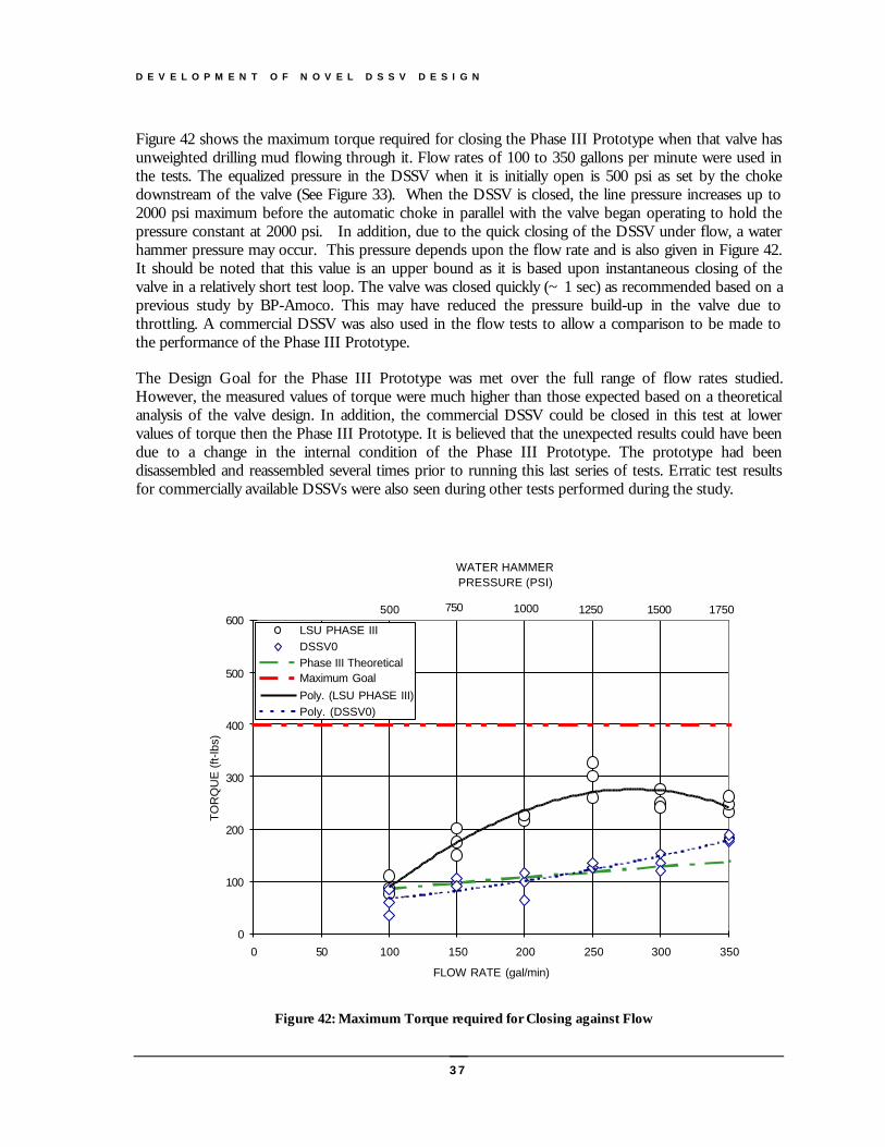
D E V E L O P M E N T O F N O V E L D S S V D E S I G N
37
Figure 42 shows the maximum torque required for closing the Phase III Prototype when that valve hasunweighted drilling mud flowing through it. Flow rates of 100 to 350 gallons per minute were used inthe tests. The equalized pressure in the DSSV when it is initially open is 500 psi as set by the chokedownstream of the valve (See Figure 33). When the DSSV is closed, the line pressure increases up to2000 psi maximum before the automatic choke in parallel with the valve began operating to hold thepressure constant at 2000 psi. In addition, due to the quick closing of the DSSV under flow, a waterhammer pressure may occur. This pressure depends upon the flow rate and is also given in Figure 42.It should be noted that this value is an upper bound as it is based upon instantaneous closing of thevalve in a relatively short test loop. The valve was closed quickly (~ 1 sec) as recommended based on aprevious study by BP-Amoco. This may have reduced the pressure build-up in the valve due tothrottling. A commercial DSSV was also used in the flow tests to allow a comparison to be made tothe performance of the Phase III Prototype.
The Design Goal for the Phase III Prototype was met over the full range of flow rates studied.However, the measured values of torque were much higher than those expected based on a theoreticalanalysis of the valve design. In addition, the commercial DSSV could be closed in this test at lowervalues of torque then the Phase III Prototype. It is believed that the unexpected results could have beendue to a change in the internal condition of the Phase III Prototype. The prototype had beendisassembled and reassembled several times prior to running this last series of tests. Erratic test resultsfor commercially available DSSVs were also seen during other tests performed during the study.
12501000750
WATER HAMMER PRESSURE (PSI)
0
100
200
300
400
500
600
0 50 100 150 200 250 300 350
FLOW RATE (gal/min)
TO
RQ
UE
(ft-
lbs)
LSU PHASE IIIDSSV0Phase III TheoreticalMaximum GoalPoly. (LSU PHASE III)Poly. (DSSV0)
1500 1750500
Figure 42: Maximum Torque required for Closing against Flow
D E V E L O P M E N T O F D S S V S T O R A G E S T A N D
38
Development of DSSV Storage Stand
It was observed in the test program that the torque required for operating a DSSVchanged with time and use. This is not surprising since the internal moving partsare exposed to the slurries periodically pumped through the valve and toweathering. In addition, the lack of lubrication of the mating parts between thestem and the ball more susceptible to binding if some parts are slightly out oftolerance. The purpose of this phase of the research program was to design a storagecontainer that will preserve DSSVs in a like new working condition and allow foreasy accessibility at the rig floor, thus resulting in improved reliability.
he design goals were determined by the student design team after talking with a number ofdifferent drilling operators. It was found that more than one size DSSV is often required onthe rig floor at all times making it necessary for the stand to accommodate more than oneDSSV. The storage container must hold the largest diameter of DSSVs listed in API
Specification 7, which is 7.875 inches. In order to maintain the DSSVs in a like new condition, it isimportant that corrosion is prevented and that debris is not allowed to solidify on the movingcomponents. In order to account for the quick retrieval of the DSSV, in less than 10 seconds, theremust be a fast and easy way of removing it from storage. Since the valves are also used off shore,the container and its components must be environmentally safe. Due to the corrosive environmentoffshore the stand must be made to resist all conditions and maintain its integrity for a design life offive years. In addition, it was believed that industry would accept the new technology more readily ifthe cost of the unit were below $4,000.
DesignThe design proposed is a storage structure, containing four storage cylinders. Each storage cylindercontains enough oil for a DSSV stored in the cylinder to be immersed in oil. A mechanism toquickly lift the DSSV out of the oil bath is driven by a hydraulic pump. In the prototype, the pumpis manually actuated to supply the required fluid and pressure to lift each valve from its cylinder. Asingle fluid reservoir located centrally, supplies oil to the pump. Machine drawings for the prototypestorage structure are given in Appendix B.
The storage stand consists of two basic components: the storage structure and the hydraulic system.The storage structure includes the all the components that act as containment, including a side plates,bottom plate, lid, and maintenance panel. The hydraulic system consists of all parts used to store thevalves in the bath as well as those components which raise or lower the valves. The basic
Chapter
5
T
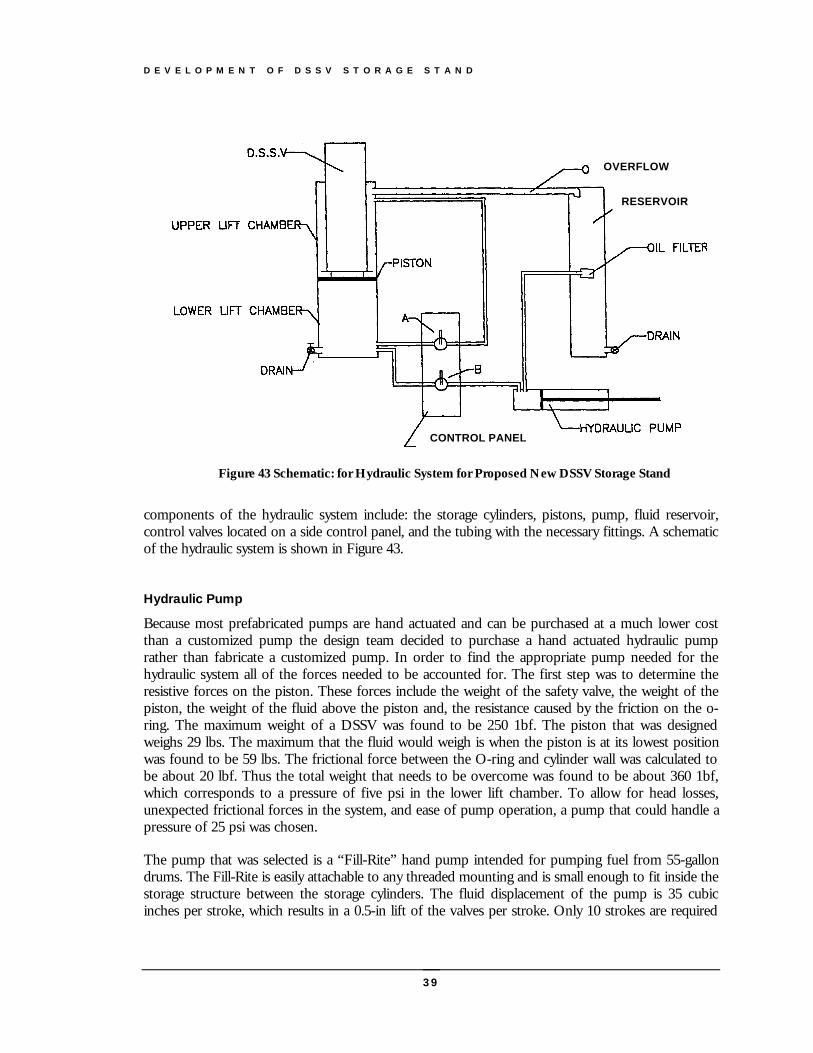
D E V E L O P M E N T O F D S S V S T O R A G E S T A N D
39
components of the hydraulic system include: the storage cylinders, pistons, pump, fluid reservoir,control valves located on a side control panel, and the tubing with the necessary fittings. A schematicof the hydraulic system is shown in Figure 43.
Hydraulic Pump
Because most prefabricated pumps are hand actuated and can be purchased at a much lower costthan a customized pump the design team decided to purchase a hand actuated hydraulic pumprather than fabricate a customized pump. In order to find the appropriate pump needed for thehydraulic system all of the forces needed to be accounted for. The first step was to determine theresistive forces on the piston. These forces include the weight of the safety valve, the weight of thepiston, the weight of the fluid above the piston and, the resistance caused by the friction on the o-ring. The maximum weight of a DSSV was found to be 250 1bf. The piston that was designedweighs 29 lbs. The maximum that the fluid would weigh is when the piston is at its lowest positionwas found to be 59 lbs. The frictional force between the O-ring and cylinder wall was calculated tobe about 20 lbf. Thus the total weight that needs to be overcome was found to be about 360 1bf,which corresponds to a pressure of five psi in the lower lift chamber. To allow for head losses,unexpected frictional forces in the system, and ease of pump operation, a pump that could handle apressure of 25 psi was chosen.
The pump that was selected is a “Fill-Rite” hand pump intended for pumping fuel from 55-gallondrums. The Fill-Rite is easily attachable to any threaded mounting and is small enough to fit inside thestorage structure between the storage cylinders. The fluid displacement of the pump is 35 cubicinches per stroke, which results in a 0.5-in lift of the valves per stroke. Only 10 strokes are required
OVERFLOW
RESERVOIR
CONTROL PANEL
Figure 43 Schematic: for Hydraulic System for Proposed New DSSV Storage Stand

D E V E L O P M E N T O F D S S V S T O R A G E S T A N D
40
to raise the valves the desired 5 inches. Each stroke of the pump took less than 1 second to executeallowing the minimum lift time requirement to be met. Also, the Fill-Rite operates at maximumpressure of 25 psi.
A check valve was placed at the inlet of the control panel to relieve any pressure that the pumpwould experience while the valves were in their lifted positions. The check valve holds the pressureof the fluid and valve weight exerted when the valves are completely lifted. The maximum pressurethe check valve can withstand is 250 psi making it more that sufficient to handle the pressure exerted.This was a precautionary measure implemented to improve the life and reliability of the hydraulicpump.
Hydraulic Cylinders
The hydraulic cylinders were designed to accommodate all sizes of DSSVs listed in API spec 7. Themaximum height of a safety valve was found to be 2 inches. The maximum size that the cylinderscan hold is 30 inches. The largest outer diameter of a safety valve was determined to be 7.875 inchesso, the cylinders were made to hold valves up to 9.5 inches in diameter. An overflow pipe waswelded on to the top of the hydraulic cylinders. One-inch pipe was welded below the over flow toallow for the flow from the lower chamber to the upper chamber. Also, one-inch pipe was weldedat the bottom of the cylinder to allow the fluid to flow out of the lower chamber. To attach thecylinders to the bottom plate of the outer storage container, three steel feet were welded to thebottom of each of the cylinders.
For a piston cylinder devise to work properly there are many factors that must be considered duringthe design. A surface finish between 8 to 16 micro-inches was selected to minimize frictional forces.A Nitrile O-ring material was selected to be compatible with the oil used in the hydraulic system andoil bath. A gasket width of .210-in was selected for the pump and .275-in for the lift. Since thepressure requirements were very low for a piston, a large tolerance could be used. This helpedprovide a low-cost construction process.
One of the concerns of the proposed design was the possibility of the DSSV tipping over duringremoval or resting on the inside wall of the storage cylinder. To prevent lateral movement of theDSSV, a threaded shaft was inserted into the piston. The maximum allowable tilt angle with the rodinserted is 7 degrees or 0.75 inches laterally. The rod was designed against bending and shear failure.The rod is 314 stainless steel and the dimensions are 10 inches long with a minor diameter of 7/8inch on the threaded part located at the base of the piston. Using the lateral load of 250 pounds andthe dimensions and material properties of the rod, it was determined that the rod had a factor ofsafety of 1.3 against bending failure and 240 against shear failure.
Fluid Reservoir
The reservoir was built to store extra fluid that gets displaced when safety valves are inserted and tocollect drilling fluid solids that settles out of the oil. The reservoir is made of 10-inch OD steel pipewith four two-inch openings for the overflow pipes that lead to each cylinder. There is also a one-inch drain at the bottom to allow for cleaning. The reservoir was attached to the pump intake usingone-inch pipe located 10 inches from the bottom of the reservoir. It was put near the center of thereservoir so the only oil would get sucked out to the pump in the event water and solids began
D E V E L O P M E N T O F D S S V S T O R A G E S T A N D
41
collecting in the bottom of the reservoir. Three steel feet were welded to the bottom of the reservoirto attach it to the bottom plate.
Hydraulic Fluid
The hydraulic fluid must bathe and lubricate internal valve parts and create a non-corrosiveenvironment ensuring the valve is in a “like-new” condition if needed. Next, the fluid must beenvironmentally friendly, in order to be compatible with offshore use. The hydraulic fluid must alsohave the versatility to remain operable under the range of temperatures experienced and maintain areasonable viscosity to allow for easy pumping. The viscosity of the hydraulic fluid is not a realfactor in the performance of the system due to the low pressures and velocities. Additionally, thehead loss the hydraulic fluid experiences while being pumped through the system is negligible due tothe large diameters of tubing and valves.
The fluid selected is called EAL-224H Hydraulic Fluid, and is produced by Mobil. The EAL-224Hhas excellent corrosion and rust resistance creating an excellent environment for the valves. Inaddition, 224H is recommended for use between 0-180 degrees Fahrenheit. This temperature wasfelt to be suitable for rig floor conditions. The 224H is not only non-toxic, but is also bio-degradable. It is recommended in marine applications.
Control Panel
Since there is only one pump for the four hydraulic lifts, a control panel was needed to direct thefluid flow that will determine which of the DSSVs is accessed or stored. To do this, hydraulic lineswere run to a control panel containing ball valves. In order to lift a DSSV, the ball valve for thatcylinder is opened and the drain valve is closed. The valve positions are reversed when lowering avalve into the storage position.
Storage Structure
Since the DSSV Phase III valve is 27 inches long, and most commercial valves are no longer than 32inches in length, a height for the storage stand of 3 feet was selected. In order to house a maximumof four valves with an outer diameter of 6 to 8 inches and have a small footprint on the rig floorarea, a 3-foot cubic stand was chosen.
The materials considered for the stand construction included stainless steel, aluminum, and carbonsteel. Aluminum would have been a good choice as far as weight and moderate strength, but failedin the area of corrosion resistance. Stainless steel was strongly considered because it is non-corrosive,has high strength, and is very durable. However, manufacturing costs would have caused the designgoal to be exceeded. After consulting with several oil-field service personnel and steel distributors, itwas discovered that the vast majority of containers used offshore are made from regular carbonsteel that has been sandblasted and painted. The design chose carbon steel for construction of theprototype DSSV Storage Stand.
The components of the storage structure considered were the bottom plate, side plates, back wall,the lid, and maintenance panel. Due to the heavy weight of the hydraulic system, the bottom plate
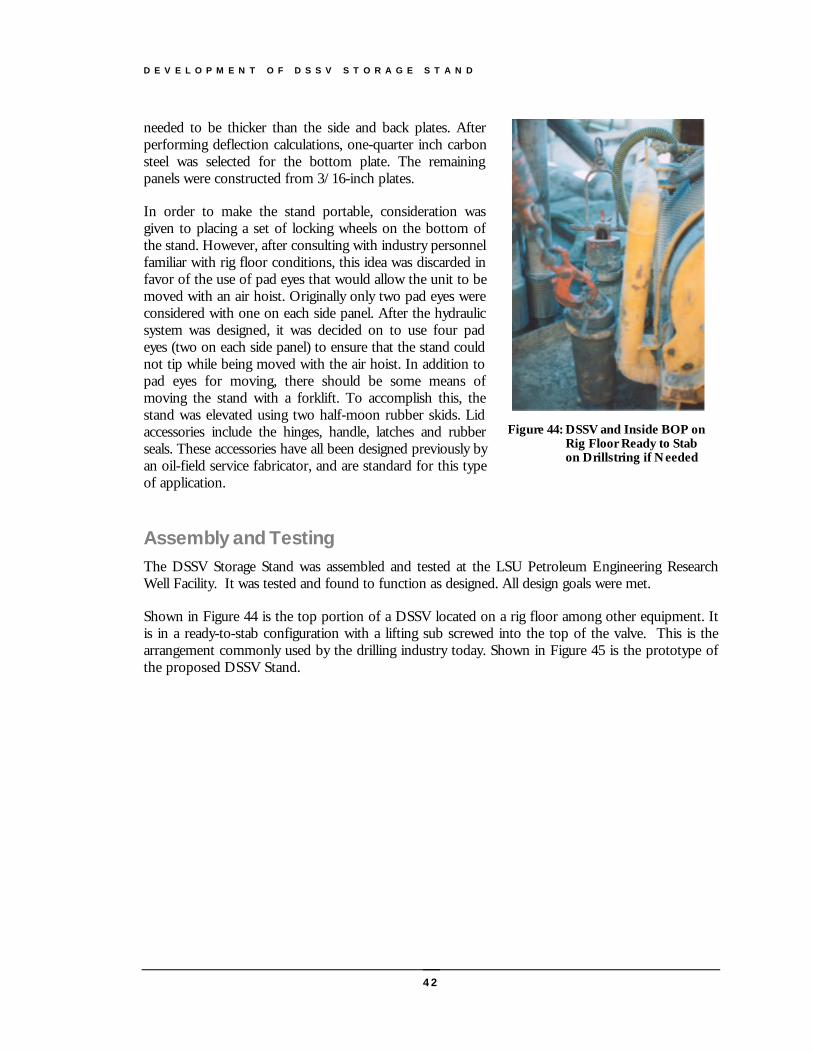
D E V E L O P M E N T O F D S S V S T O R A G E S T A N D
42
needed to be thicker than the side and back plates. Afterperforming deflection calculations, one-quarter inch carbonsteel was selected for the bottom plate. The remainingpanels were constructed from 3/16-inch plates.
In order to make the stand portable, consideration wasgiven to placing a set of locking wheels on the bottom ofthe stand. However, after consulting with industry personnelfamiliar with rig floor conditions, this idea was discarded infavor of the use of pad eyes that would allow the unit to bemoved with an air hoist. Originally only two pad eyes wereconsidered with one on each side panel. After the hydraulicsystem was designed, it was decided on to use four padeyes (two on each side panel) to ensure that the stand couldnot tip while being moved with the air hoist. In addition topad eyes for moving, there should be some means ofmoving the stand with a forklift. To accomplish this, thestand was elevated using two half-moon rubber skids. Lidaccessories include the hinges, handle, latches and rubberseals. These accessories have all been designed previously byan oil-field service fabricator, and are standard for this typeof application.
Assembly and TestingThe DSSV Storage Stand was assembled and tested at the LSU Petroleum Engineering ResearchWell Facility. It was tested and found to function as designed. All design goals were met.
Shown in Figure 44 is the top portion of a DSSV located on a rig floor among other equipment. Itis in a ready-to-stab configuration with a lifting sub screwed into the top of the valve. This is thearrangement commonly used by the drilling industry today. Shown in Figure 45 is the prototype ofthe proposed DSSV Stand.
Figure 44: DSSV and Inside BOP onRig Floor Ready to Stabon Drillstring if Needed
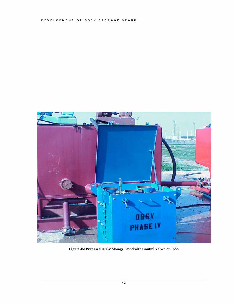
D E V E L O P M E N T O F D S S V S T O R A G E S T A N D
43
Figure 45: Proposed DSSV Storage Stand with Control Valves on Side.
C O N C L U S I O N S A N D R E C O M M E N D A T I O N S
44
Conclusions and Recommendations
This study was undertaken by LSU under the sponsorship of the MMS to improvesafety and reduce risk of blowouts through the drill string. MMS has beenmandated by congress to insure that the best available and safest technology isutilized by industry in developing our natural resources on the outer continentalshelf.
robust Drill String Safety Valves DSSV is difficult to design because the DSSV must fit in thedrillstring and be full-opening enough to allow wireline work to be done through the valve.The valves have been shown to have one of the highest failure rates of the blowout control
equipment routinely used on drilling rigs. Blowouts have occurred on a number of occasions when aDSSV could not be closed to stop flow from the well up the drillstring. Other failure modes havealso been reported that have not caused blowouts but have made well control difficult to achieve.
Most DSSVs that are commercially available are primarily quarter-turn ball valves in which the ballfloats between fixed seats and depend on well pressure to force the closed ball against a seat toform a seal. This design minimizes the crushing force placed on the ball and distributes stressesthrough the seats over a wide area. However, interference between parts can result during ballrotation if dimensional tolerances are not met. A relatively new DSSV design has recently becomeavailable that utilizes a trunnion mounted fixed ball and floating seats. This design reduces the risk ofinterference between parts during ball rotation but results in more concentrated stresses in the valvestem and ball.
In this project, DSSV failure modes were studied in detail and procedures for reducing the risk ofblowouts due to a DSSV failure were identified. A novel DSSV design was explored that used atrunnion-mounted ball and spring loaded seats was constructed and tested by an interdisciplinaryresearch team composed of Petroleum Engineering and Mechanical Engineering seniors and faculty.The novel design results in operating torque being less affected by internal pressure but also results inmore concentrated stresses in the valve stem. The test program indicated that the design objectivesof the new design were achieved. The test program also revealed that the torque required to operatea DSSV type ball valve can change with use (especially after being operated in a high torquecondition), with internal exposure to drilling slurries, and with non-use and exposure to the elements.In addition to a new valve design, a new DSSV storage stand was designed and tested that couldmaintain a DSSV on the rig floor in a “like-new” condition.
As a result of the work done in this study, the following conclusions and recommendations weremade:
Chapter
6
A
C O N C L U S I O N S A N D R E C O M M E N D A T I O N S
45
Conclusions1. Failure of a DSSV to close against a high flow rate or under high pressure has resulted
in a number of blowouts.2. Test results obtained and this study and results published in the literature show that the
torque required for operating a DSSV increase with internal valve pressure and canexceed 400 ft-lbf at pressures as low as 1000 psi.
3. The new prototype design developed in this work shows promise of reducing theoperating torque at high pressures.
4. High pressure on a DSSV valve before closing can occur when there is a significantlength of piping and or restrictions downstream of the DSSV.
5. The link between the ball and stem in a DSSV is generally a two piece design to facilitatedisassembly and rebuilding the internal components of the valve. This design issusceptible to binding during rotation of the ball under flow or pressure if dimensionaltolerances are not closely observed during manufacturing and assembly.
6. Low cost DSSVs utilize a threaded two-piece body construction to allow the valve tobe disassembled and rebuilt in the field. The torque used to remake the body threadscan affect critical dimensional tolerances of the component placement in the valve body.Applying excessive torque across the valve body when making up the valve in thedrillstring can bind the ball between the seats.
7. Redundant barriers to blowouts are needed for the drillstring during tripping operationssimilar to the use of redundant barriers provided in the blowout preventer stack forstopping a flow up the annulus.
8. Experience has shown that maintaining multiple DSSVs available on the rig-floor asstabbing valves does not always prevent blowouts.
Recommendations1. The DSSV intended for use as a stabbing valve to stop flow through the drillstring during tripping
operations should not be used in the drillstring for other operations. The stabbing valve should bemaintained in a “like-new“ condition and used only during periodic pressure testing with fresh water.
2. Operators and/or drilling contractors should check threads, valve wrench, and lift sub on the stabbingvalve and actuate the stabbing valve close and open each tour.
3. Operators and/or drilling contractors should use a drillstring float whenever practical to provideredundant protection against a high-rate flow through the drill-string during tripping operations.
4. When floats are not used, shear rams are recommended for redundant protection against blowoutsthrough the drillstring during tripping operations.
5. Drill String Safety Valves should not be the only means for stopping flow from the drillstring at thesurface when reverse circulating the well during completion operations. Flow should be routed throughhydraulically operated valves and a choke manifold.
6. Drill string safety valves should not be the only means for stopping flow through the drill string whensignificant piping and flow restrictions are present above the valve.
B I B L I O G R A P H Y
46
Bibliography
1. Chilingarian, G.V., Drilling and Drilling Fluids, Elsevier Scientific PublishingCompany, Amsterdam, 1981
2. Piper, C.F, Mud Equipment Manual, Gulf Publishing Company, Houston, 1985.
3. Tarr, Brian A.: “Research Targets Drillstring Safety Valve Improvements,” Gas Tips(Spring, 1996).
4. Tarr, B.A. et. Al, “New Generation Drill String Safety Valves,” IADC/SPE Paper39320, IADC/SPE Drilling Conference (March 306, 1998), Dallas, TX.
5. Hauser, William: “Minerals Management Service (MMS) Review of Blowout Preventer(BOP) Testing and Maintenance Requirements for Drilling Activities on the OuterContinental Shelf (OCS),” paper presented at the IADC Well Control Conference ofthe Americas, 1995.
6. Dayton, R. W.; Sleeve Bearing Materials. American Society for Metals, 1949.
7. Gupta, Pradeep K.; Advanced Dynamics of Rolling Elements. Springer-Verlag NewYork Inc., 1984.
8. Harris, Tedric A.; Rolling Bearing Analysis. John Wiley & Sons, Inc., 1966.
9. Mischke, Charles R. and Joseph Edward Shigley; Mechanical Engineering Design.McGraw-Hill, Inc., 1989.
10. Warring, R.H.; Seals and Sealing Handout; Gulf Publishing Company, 1981.

M A C H I N E D R A W I N G S F O R P H A S E I I I P R O T O T Y P E D S S V
47
Phase III Prototype DSSV
This appendix contains the machine drawings for the Phase III prototype DSSV.
Appendix
A

M A C H I N E D R A W I N G S F O R P H A S E I I I P R O T O T Y P E D S S V
48

M A C H I N E D R A W I N G S F O R P H A S E I I I P R O T O T Y P E D S S V
49
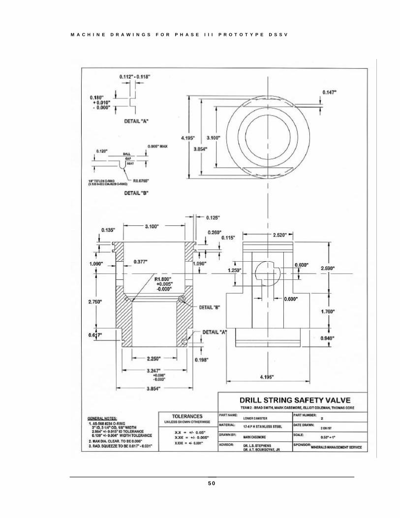
M A C H I N E D R A W I N G S F O R P H A S E I I I P R O T O T Y P E D S S V
50
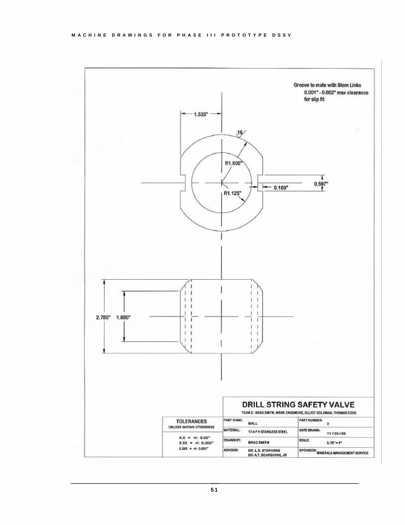
M A C H I N E D R A W I N G S F O R P H A S E I I I P R O T O T Y P E D S S V
51
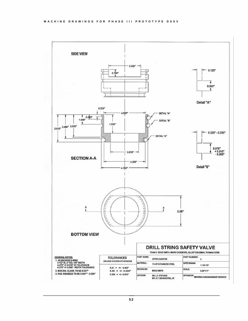
M A C H I N E D R A W I N G S F O R P H A S E I I I P R O T O T Y P E D S S V
52
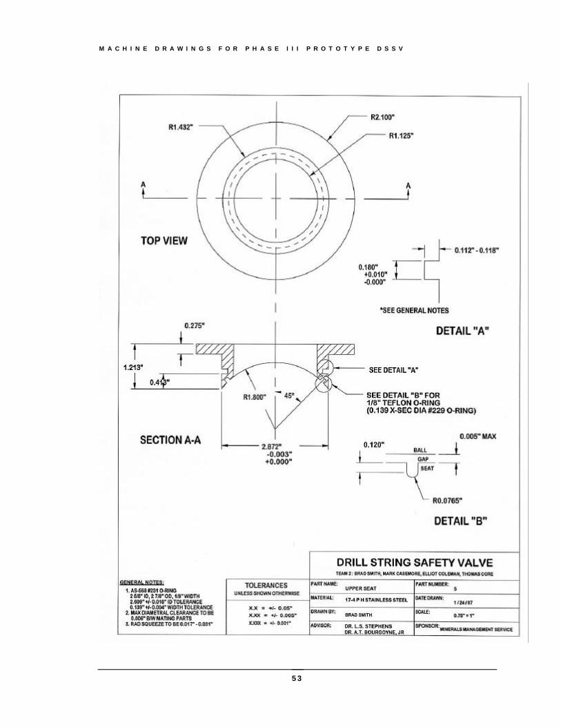
M A C H I N E D R A W I N G S F O R P H A S E I I I P R O T O T Y P E D S S V
53
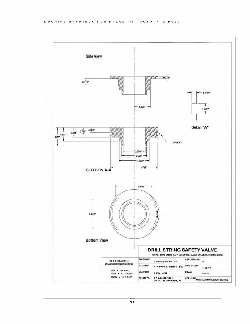
M A C H I N E D R A W I N G S F O R P H A S E I I I P R O T O T Y P E D S S V
54
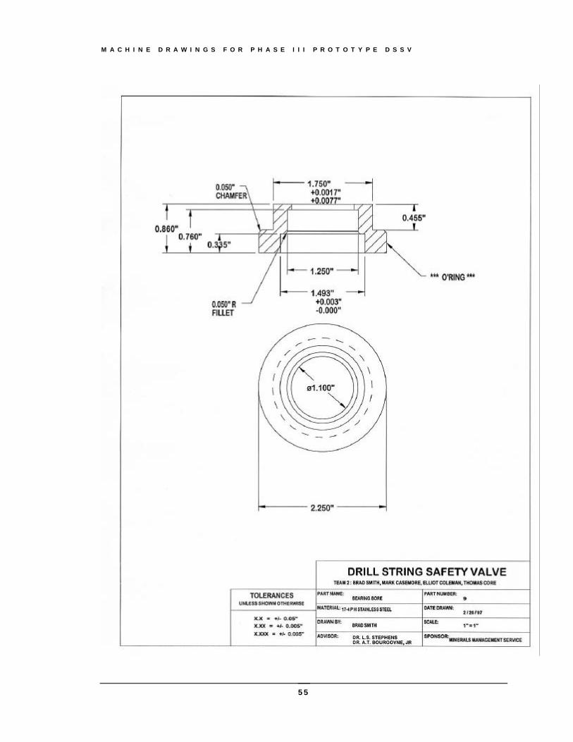
M A C H I N E D R A W I N G S F O R P H A S E I I I P R O T O T Y P E D S S V
55
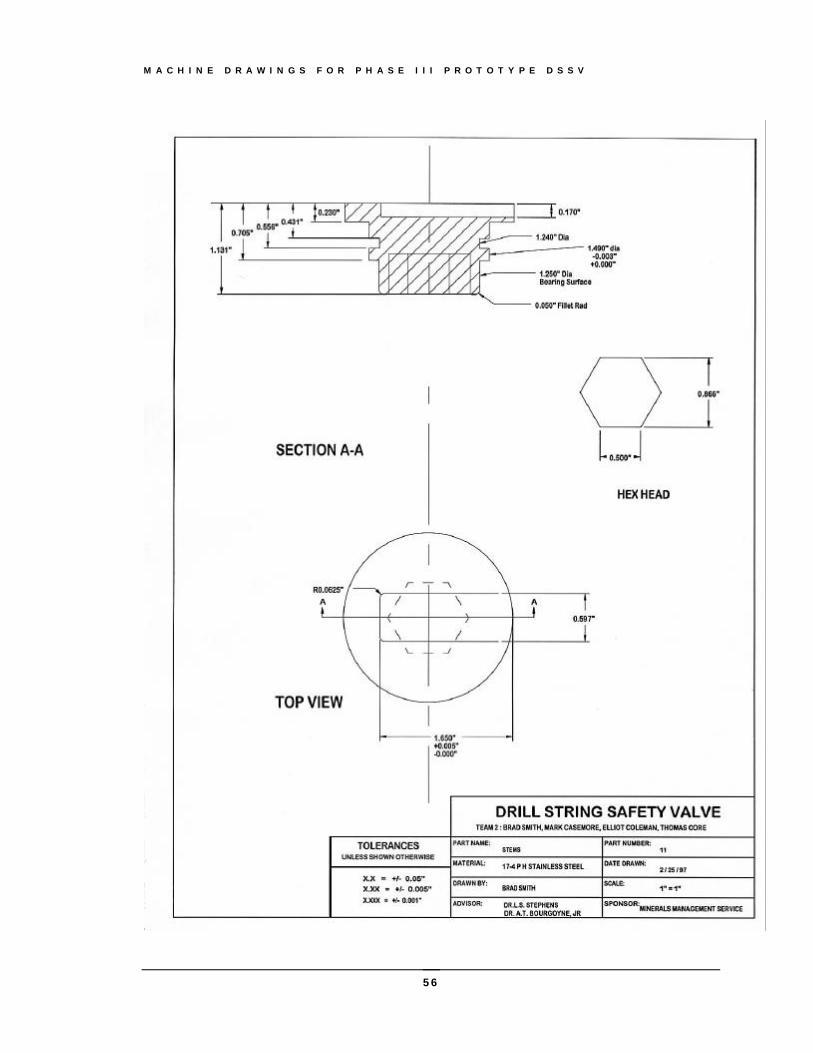
M A C H I N E D R A W I N G S F O R P H A S E I I I P R O T O T Y P E D S S V
56
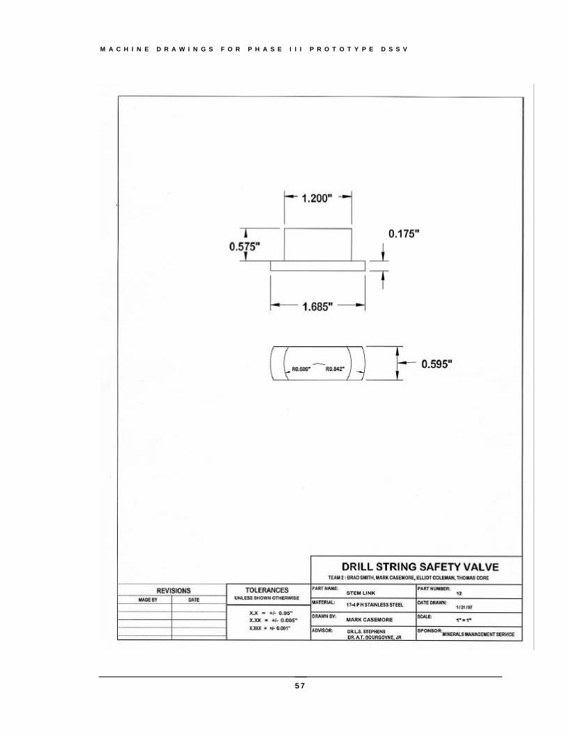
M A C H I N E D R A W I N G S F O R P H A S E I I I P R O T O T Y P E D S S V
57

Phase IV Prototype DSSV Storage Stand
This appendix contains the machine drawings for the Phase IV prototype DSSV Storage Stand..
Appendix
B
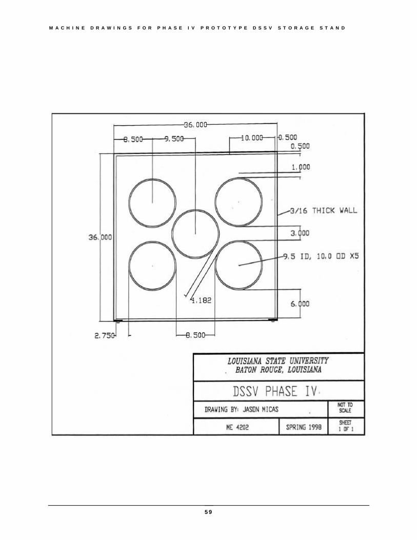
M A C H I N E D R A W I N G S F O R P H A S E I V P R O T O T Y P E D S S V S T O R A G E S T A N D
59
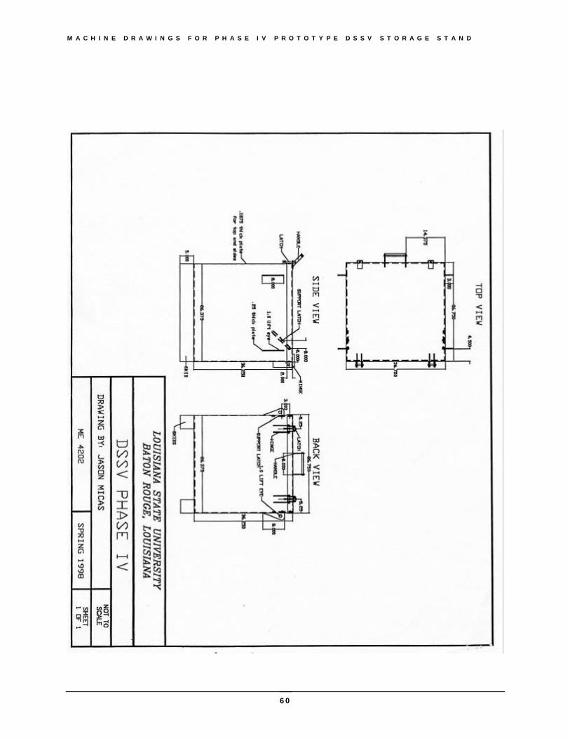
M A C H I N E D R A W I N G S F O R P H A S E I V P R O T O T Y P E D S S V S T O R A G E S T A N D
60

M A C H I N E D R A W I N G S F O R P H A S E I V P R O T O T Y P E D S S V S T O R A G E S T A N D
61