Embed Size (px)
Citation preview
20-12-2008 Im310 Page 1
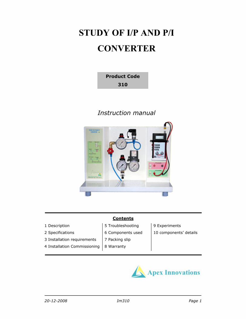
STUDY OF I/P AND P/I
CONVERTER
Instruction manual
Contents
1 Description
2 Specifications
3 Installation requirements
4 Installation Commissioning
5 Troubleshooting
6 Components used
7 Packing slip
8 Warranty
9 Experiments
10 components’ details
Product Code
310
Apex Innovations
20-12-2008 Im310 Page 2
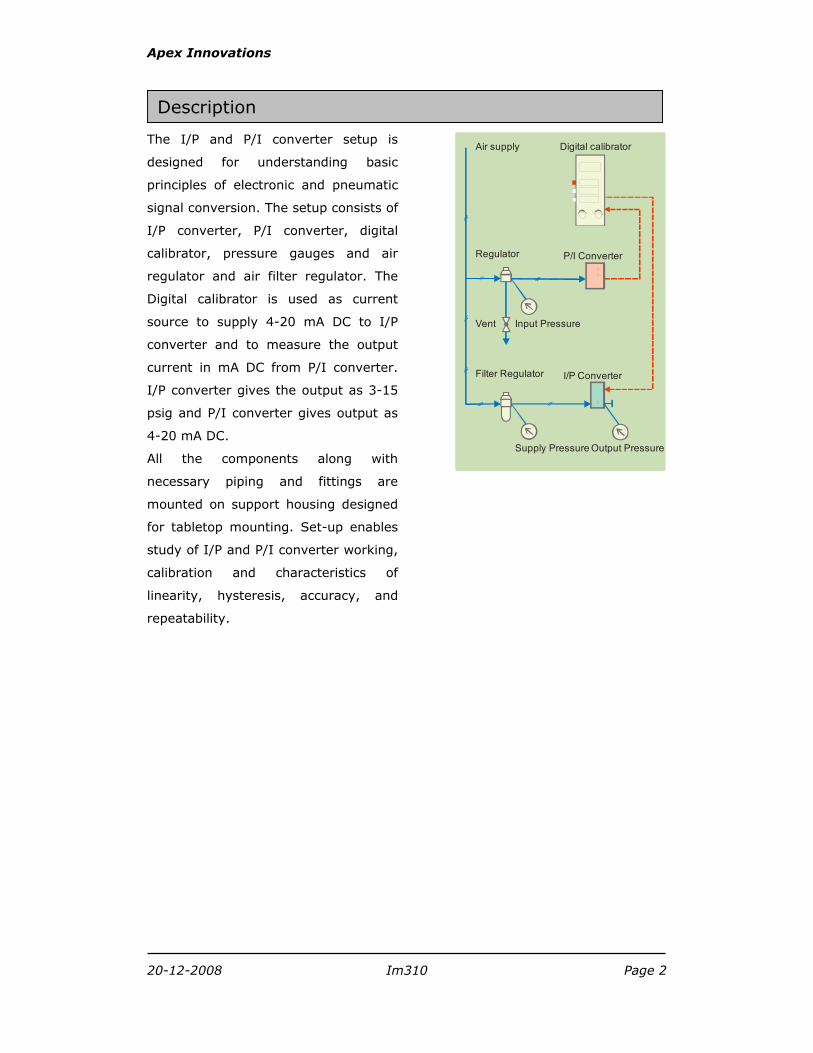
The I/P and P/I converter setup is
designed for understanding basic
principles of electronic and pneumatic
signal conversion. The setup consists of
I/P converter, P/I converter, digital
calibrator, pressure gauges and air
regulator and air filter regulator. The
Digital calibrator is used as current
source to supply 4-20 mA DC to I/P
converter and to measure the output
current in mA DC from P/I converter.
I/P converter gives the output as 3-15
psig and P/I converter gives output as
4-20 mA DC.
All the components along with
necessary piping and fittings are
mounted on support housing designed
for tabletop mounting. Set-up enables
study of I/P and P/I converter working,
calibration and characteristics of
linearity, hysteresis, accuracy, and
repeatability.
Supply Pressure
Input PressureVent
P/I Converter
Filter Regulator
Regulator
I/P Converter
Air supply
Output Pressure
Digital calibrator
Description
Apex Innovations
20-12-2008 Im310 Page 3
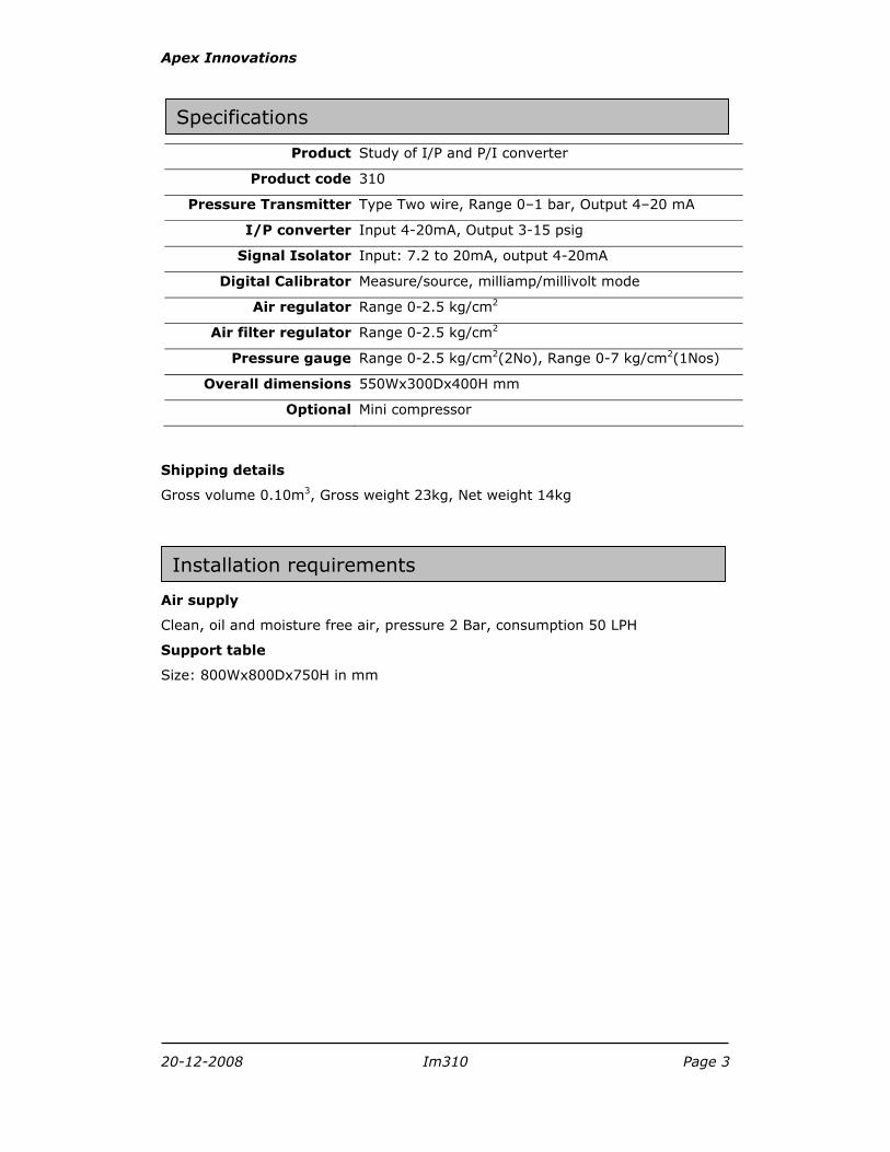
Product Study of I/P and P/I converter
Product code 310
Pressure Transmitter Type Two wire, Range 0–1 bar, Output 4–20 mA
I/P converter Input 4-20mA, Output 3-15 psig
Signal Isolator Input: 7.2 to 20mA, output 4-20mA
Digital Calibrator Measure/source, milliamp/millivolt mode
Air regulator Range 0-2.5 kg/cm2
Air filter regulator Range 0-2.5 kg/cm2
Pressure gauge Range 0-2.5 kg/cm2(2No), Range 0-7 kg/cm2(1Nos)
Overall dimensions 550Wx300Dx400H mm
Optional Mini compressor
Shipping details
Gross volume 0.10m3, Gross weight 23kg, Net weight 14kg
Air supply
Clean, oil and moisture free air, pressure 2 Bar, consumption 50 LPH
Support table
Size: 800Wx800Dx750H in mm
Specifications
Installation requirements
Apex Innovations
20-12-2008 Im310 Page 4
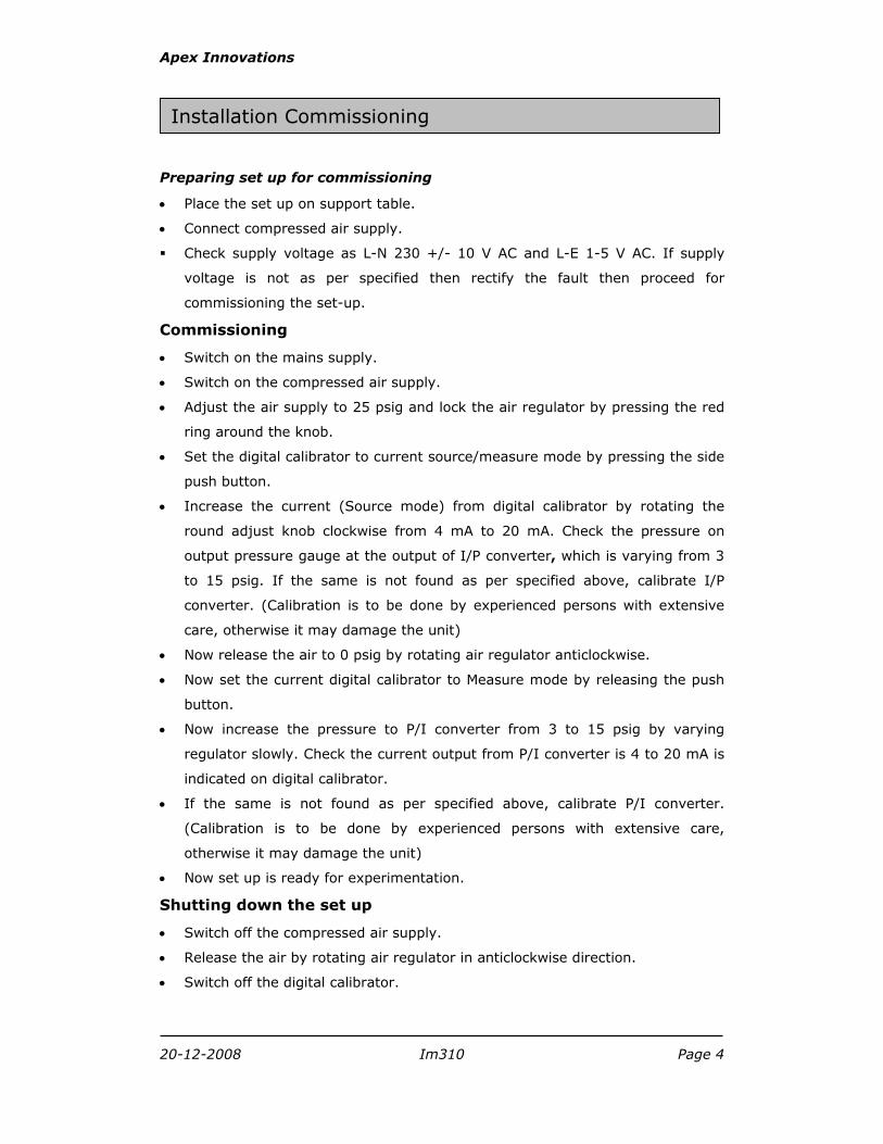
Preparing set up for commissioning
• Place the set up on support table.
• Connect compressed air supply.
Check supply voltage as L-N 230 +/- 10 V AC and L-E 1-5 V AC. If supply
voltage is not as per specified then rectify the fault then proceed for
commissioning the set-up.
Commissioning
• Switch on the mains supply.
• Switch on the compressed air supply.
• Adjust the air supply to 25 psig and lock the air regulator by pressing the red
ring around the knob.
• Set the digital calibrator to current source/measure mode by pressing the side
push button.
• Increase the current (Source mode) from digital calibrator by rotating the
round adjust knob clockwise from 4 mA to 20 mA. Check the pressure on
output pressure gauge at the output of I/P converter, which is varying from 3
to 15 psig. If the same is not found as per specified above, calibrate I/P
converter. (Calibration is to be done by experienced persons with extensive
care, otherwise it may damage the unit)
• Now release the air to 0 psig by rotating air regulator anticlockwise.
• Now set the current digital calibrator to Measure mode by releasing the push
button.
• Now increase the pressure to P/I converter from 3 to 15 psig by varying
regulator slowly. Check the current output from P/I converter is 4 to 20 mA is
indicated on digital calibrator.
• If the same is not found as per specified above, calibrate P/I converter.
(Calibration is to be done by experienced persons with extensive care,
otherwise it may damage the unit)
• Now set up is ready for experimentation.
Shutting down the set up
• Switch off the compressed air supply.
• Release the air by rotating air regulator in anticlockwise direction.
• Switch off the digital calibrator.
Installation Commissioning
Apex Innovations
20-12-2008 Im310 Page 5
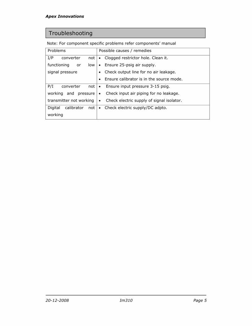
Note: For component specific problems refer components’ manual
Problems Possible causes / remedies
I/P converter not
functioning or low
signal pressure
• Clogged restrictor hole. Clean it.
• Ensure 25-psig air supply.
• Check output line for no air leakage.
• Ensure calibrator is in the source mode.
P/I converter not
working and pressure
transmitter not working
• Ensure input pressure 3-15 psig.
• Check input air piping for no leakage.
• Check electric supply of signal isolator.
Digital calibrator not
working
• Check electric supply/DC adpto.
Troubleshooting
Apex Innovations
20-12-2008 Im310 Page 6
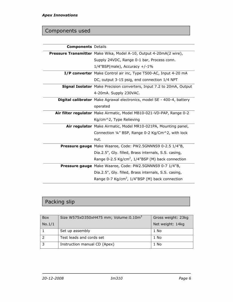
Components Details
Pressure Transmitter Make Wika, Model A-10, Output 4-20mA(2 wire),
Supply 24VDC, Range 0-1 bar, Process conn.
1/4"BSP(male), Accuracy +/-1%
I/P converter Make Control air inc, Type T500-AC, Input 4-20 mA
DC, output 3-15 psig, end connection 1/4 NPT
Signal Isolator Make Precision converters, Input 7.2 to 20mA, Output
4-20mA. Supply 230VAC.
Digital calibrator Make Agrawal electronics, model SE - 400-4, battery
operated
Air filter regulator Make Airmatic, Model MB10-021-VD-PAP, Range 0-2
Kg/cm^2, Type Relieving
Air regulator Make Airmatic, Model MR10-021PA, Mounting panel,
Connection ¼” BSP, Range 0-2 Kg/Cm^2, with lock
nut.
Pressure gauge Make Waaree, Code: PW2.5GNNNS9 0-2.5 1/4"B,
Dia.2.5", Gly. filled, Brass internals, S.S. casing,
Range 0-2.5 Kg/cm2, 1/4"BSP (M) back connection
Pressure gauge Make Waaree, Code: PW2.5GNNNS9 0-7 1/4"B,
Dia.2.5", Gly. filled, Brass internals, S.S. casing,
Range 0-7 Kg/cm2, 1/4"BSP (M) back connection
Box
No.1/1
Size W575xD350xH475 mm; Volume:0.10m3 Gross weight: 23kg
Net weight: 14kg
1 Set up assembly 1 No
2 Test leads and cords set 1 No
3 Instruction manual CD (Apex) 1 No
Packing slip
Components used
Apex Innovations
20-12-2008 Im310 Page 7
This product is warranted for a period of 12 months from the date of supply
against manufacturing defects. You shall inform us in writing any defect in the
system noticed during the warranty period. On receipt of your written notice,
Apex at its option either repairs or replaces the product if proved to be defective
as stated above. You shall not return any part of the system to us before
receiving our confirmation to this effect.
The foregoing warranty shall not apply to defects resulting from:
Buyer/ User shall not have subjected the system to unauthorized
alterations/ additions/ modifications.
Unauthorized use of external software/ interfacing.
Unauthorized maintenance by third party not authorized by Apex.
Improper site utilities and/or maintenance.
We do not take any responsibility for accidental injuries caused while working
with the set up.
Apex Innovations Pvt. Ltd. E9/1, MIDC, Kupwad, Sangli-416436 (Maharashtra) India
Telefax:0233-2644098, 2644398
Email: [email protected] Web: www.apexinnovations.co.in
Warranty
Apex Innovations
20-12-2008 Im310 Page 8
In recent years the performance requirements for process plants have become
increasingly difficult to satisfy. Stronger competition, tougher environmental and
safety regulations, and rapidly changing economic conditions have been key
factors in the tightening of plant product quality specifications. A further
complication is that modern processes have become more difficult to operate
because of the trend toward larger, more highly integrated plants with smaller
surge capacities between the various processing units. Such plants give the
operator little opportunity to prevent upsets from propagating from one unit to
other interconnected units. In view of increased emphasis placed on safe, efficient
plant operation, it is only natural that the subject of process control has become
increasingly important in recent years. In fact, without process control it would
not be possible to operate most modern processes safely and profitably, while
satisfying plant quality standards.
Commonly used terms in process control
Linearity
Linearity indicates for each value of the input variable there exists one unique
value of the output variable. We see that linear relationship can be represented
by the equation of a straight line:
y=mx+C
Where,
y = output of measure
m = slope of straight line
x = Variable to be measure
C = offset or intercept of straight line
Hysteresis
Hystersis is a predictable error resulting from differences in the transfer functions
when a reading is taken from above or below the value to be measured.
Hystersis =Output at decreasing Input – Output at increasing input.
Accuracy
This term is used to specify the maximum overall error (The algebraic difference
between the indicated value & the actual value of a measured variable is called
THEORY
Apex Innovations
20-12-2008 Im310 Page 9
the error) to be expected from a device, such as measurement of a variable.
Accuracy usually is expressed as the inaccuracy and can appear in several forms:
1. Measured variable, as the accuracy is +/-2oC in some temperature
measurement. Thus, there would be an uncertainty of +/- 2oC in any value of
temperature measured.
2. Percentage of the instrument full-scale (FS) reading. Thus, an accuracy of +/-
0.5% FS in a 5-volt full-scale range meter would mean the inaccuracy or
uncertainty in any measurement is +/-0.025 volts.
3. Percentage of instrument span, that is percentage of the range of instrument
measurement capability. Thus, for a device measuring +/-3% of span for a
20-50 psi range of pressure, the accuracy would be(+/-0.03)(50-20)=
+/-0.9psi.
4. Percentage of the actual reading. Thus, for a +/-2% of reading voltmeter, we
would have an inaccuracy of +/-0.04 volts for a reading of 2 volts.
Repeatability
Repeatability is the value of same output for given input in repeated trials is
defined as repeatability of instrument. Repeatability can be found out in % of
each reading.
Final control
Pneumatic signals
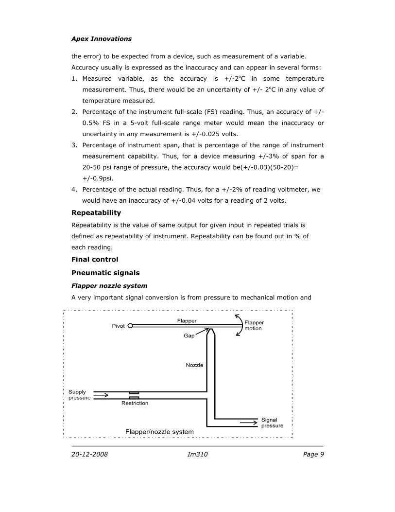
Flapper nozzle system
A very important signal conversion is from pressure to mechanical motion and
Apex Innovations
20-12-2008 Im310 Page 10
vice versa. This conversion can be provided by a flapper/nozzle system
(sometimes called a baffle /nozzle system). A diagram of this device is shown in
Fig.I below. A regulated supply of pressure, usually 20 psig, provides a source of
air through the restriction. The nozzle is open at the end where the gap exists
between the nozzle and flapper, and air escapes in this region. If the flapper
moves down and closes off the nozzle opening so that no air leaks, the signal
pressure will rise to the supply pressure. As the flapper moves away, the signal
pressure will drop because of leaking of the leaking air. Finally, when the flapper
is far away, the pressure will stabilise at some value determined by the maximum
leak through the nozzle.
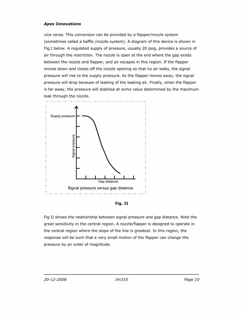
Fig. II
Fig II shows the relationship between signal pressure and gap distance. Note the
great sensitivity in the central region. A nozzle/flapper is designed to operate in
the central region where the slope of the line is greatest. In this region, the
response will be such that a very small motion of the flapper can change the
pressure by an order of magnitude.
Apex Innovations
20-12-2008 Im310 Page 11
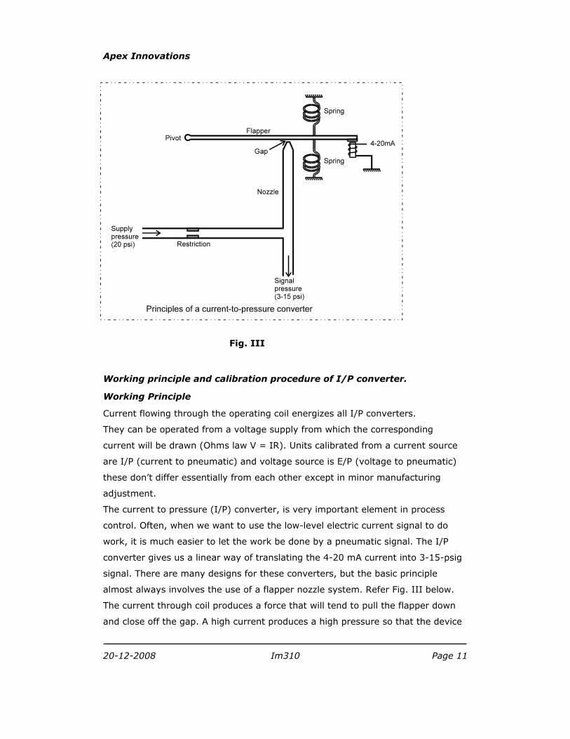
Fig. III
Working principle and calibration procedure of I/P converter.
Working Principle
Current flowing through the operating coil energizes all I/P converters.
They can be operated from a voltage supply from which the corresponding
current will be drawn (Ohms law V = IR). Units calibrated from a current source
are I/P (current to pneumatic) and voltage source is E/P (voltage to pneumatic)
these don’t differ essentially from each other except in minor manufacturing
adjustment.
The current to pressure (I/P) converter, is very important element in process
control. Often, when we want to use the low-level electric current signal to do
work, it is much easier to let the work be done by a pneumatic signal. The I/P
converter gives us a linear way of translating the 4-20 mA current into 3-15-psig
signal. There are many designs for these converters, but the basic principle
almost always involves the use of a flapper nozzle system. Refer Fig. III below.
The current through coil produces a force that will tend to pull the flapper down
and close off the gap. A high current produces a high pressure so that the device

Apex Innovations
20-12-2008 Im310 Page 12
is direct acting. Adjustment of the springs and perhaps the position relative to the
pivot to which they are attached allows the unit to calibrated so that 4 mA
corresponds to 3 psig and 20 mA corresponds to 15 psig.
Current to pneumatic converters are two-wire precision instruments designed to
convert standard industrial electrical input signals into proportional pneumatic
output signal. They are force balance instruments using a coil suspended in a
magnetic field to operate a flapper valve against a air nozzle to create back
pressure on the control diaphragm of a booster relay. They are compact robust
instruments suitable for panel or field mounting applications.
Input signal: 4-20 mA DC.
Output signal: 3-15 psi
Supply pressure: 20 psig
Calibration procedure
Generally I/P converter is calibrated for standard industrial signals as 4-20 mA
input and 3-15 psig output. These are standard factory settings and need not to
be changed.
Refer following steps to calibrate I/P converter:
1. Set digital calibrator in source mode.
2. Remove the top cover from the unit by gently prying up on the two snap-in
cover tabs.
3. Connect 20-psig supply pressure and connect input signal i.e. 4-20 mA.
4. Set the input signal to 4 mA and check the output pressure on gauge as 3
psig.
5. If the pressure is showing more or less than 3 psig then adjust zero. Turn
zero adjustment screw slowly by very small turn to obtain 3-psig pressure.
More turning of zero adjustment may damage the I/P converter.
Counterclockwise rotation increases the pressure, and clockwise rotation
decreases the pressure.
6. Set the input current signal to 20 mA and check the output pressure on gauge
as 15 psig.
7. Turn the span adjustment potentiometer very slowly by small turn to obtain
15-psig pressure. More turning of span adjustment may damage the I/P
converter.

Apex Innovations
20-12-2008 Im310 Page 13
8. Repeat step 4 to check that the desired low value (4 mA ~ 3 psig) has not
changed after adjusting the span. If necessary repeat steps 3 through 4 to
fine-tune the unit.
9. Snap the top cover in the place.
(Note: It is strongly recommended NOT to change the calibration
set per standard factory setting.)
Apex Innovations
20-12-2008 Im310 Page 14
Working principle and calibration procedure of P/I converter.
Working Principle
Pressure to current (P/I) converters is two-wire precision instrument designed to
convert standard pneumatic input signals into proportional output electrical
signal. They are compact robust instruments suitable for panel or field mounting
applications.
Input signal: 3-15 psig.
Output signal: 4-20 mA DC
Supply voltage: 24 VDC
Calibration procedure
Generally P/I converter is calibrated for standard industrial signals as 3-15 psig
input corresponds to 4-20 mA DC output. These are standard factory settings and
need not to be changed.
To adjust the zero and span settings proceed as follows:
Two adjustments for zero and span are provided in front face of unit.
1. Set digital calibrator on measure mode.
2. Connect input signal i.e. 3-15 psig.
3. Set the input signal to 3 psig and check the output current as 4 mA.
4. If the current is showing more or less than 4 mA then adjust zero on the
isolator.
5. Set the input pressure signal to 15 psig and check the output current 20 mA.
6. Turn the span adjustment potentiometer on signal
7. Repeat step 3 to check that the desired low value (3 psig ~ 4mA) has not
changed after adjusting the span. If necessary repeat steps 3 through 4 to
fine-tune the unit.
Apex Innovations
20-12-2008 Im310 Page 15
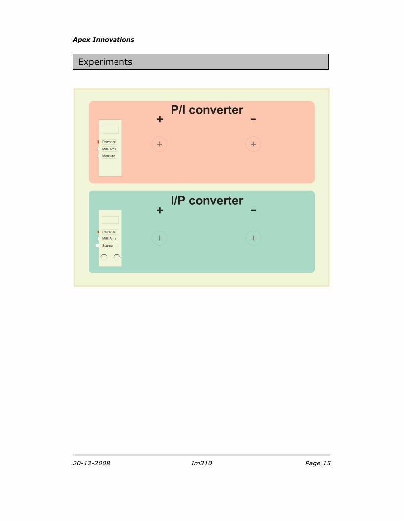
P/I converter+
Power on
Milli Amp
Measure
I/P converter+
Power on
Milli Amp
Source
Experiments
Apex Innovations
20-12-2008 Im310 Page 16
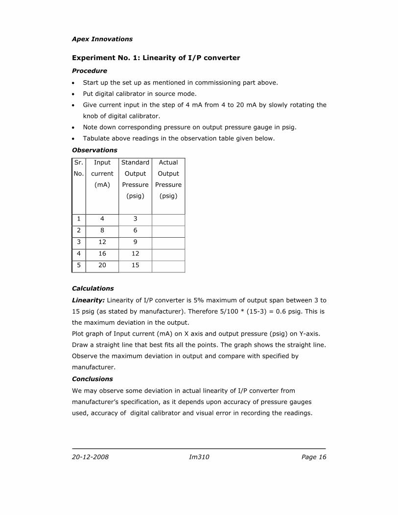
Experiment No. 1: Linearity of I/P converter
Procedure
• Start up the set up as mentioned in commissioning part above.
• Put digital calibrator in source mode.
• Give current input in the step of 4 mA from 4 to 20 mA by slowly rotating the
knob of digital calibrator.
• Note down corresponding pressure on output pressure gauge in psig.
• Tabulate above readings in the observation table given below.
Observations
Sr.
No.
Input
current
(mA)
Standard
Output
Pressure
(psig)
Actual
Output
Pressure
(psig)
1 4 3
2 8 6
3 12 9
4 16 12
5 20 15
Calculations
Linearity: Linearity of I/P converter is 5% maximum of output span between 3 to
15 psig (as stated by manufacturer). Therefore 5/100 * (15-3) = 0.6 psig. This is
the maximum deviation in the output.
Plot graph of Input current (mA) on X axis and output pressure (psig) on Y-axis.
Draw a straight line that best fits all the points. The graph shows the straight line.
Observe the maximum deviation in output and compare with specified by
manufacturer.
Conclusions
We may observe some deviation in actual linearity of I/P converter from
manufacturer’s specification, as it depends upon accuracy of pressure gauges
used, accuracy of digital calibrator and visual error in recording the readings.
Apex Innovations
20-12-2008 Im310 Page 17
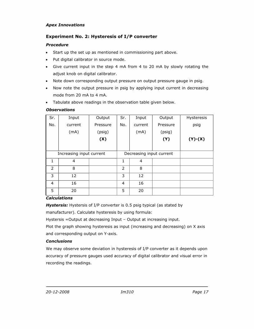
Experiment No. 2: Hysteresis of I/P converter
Procedure
• Start up the set up as mentioned in commissioning part above.
• Put digital calibrator in source mode.
• Give current input in the step 4 mA from 4 to 20 mA by slowly rotating the
adjust knob on digital calibrator.
• Note down corresponding output pressure on output pressure gauge in psig.
• Now note the output pressure in psig by applying input current in decreasing
mode from 20 mA to 4 mA.
• Tabulate above readings in the observation table given below.
Observations
Sr.
No.
Input
current
(mA)
Output
Pressure
(psig)
(X)
Sr.
No.
Input
current
(mA)
Output
Pressure
(psig)
(Y)
Hysteresis
psig
(Y)-(X)
Increasing input current Decreasing input current
1 4 1 4
2 8 2 8
3 12 3 12
4 16 4 16
5 20 5 20
Calculations
Hystersis: Hystersis of I/P converter is 0.5 psig typical (as stated by
manufacturer). Calculate hysteresis by using formula:
Hystersis =Output at decreasing Input – Output at increasing input.
Plot the graph showing hysteresis as input (increasing and decreasing) on X axis
and corresponding output on Y-axis.
Conclusions
We may observe some deviation in hysteresis of I/P converter as it depends upon
accuracy of pressure gauges used accuracy of digital calibrator and visual error in
recording the readings.
Apex Innovations
20-12-2008 Im310 Page 18
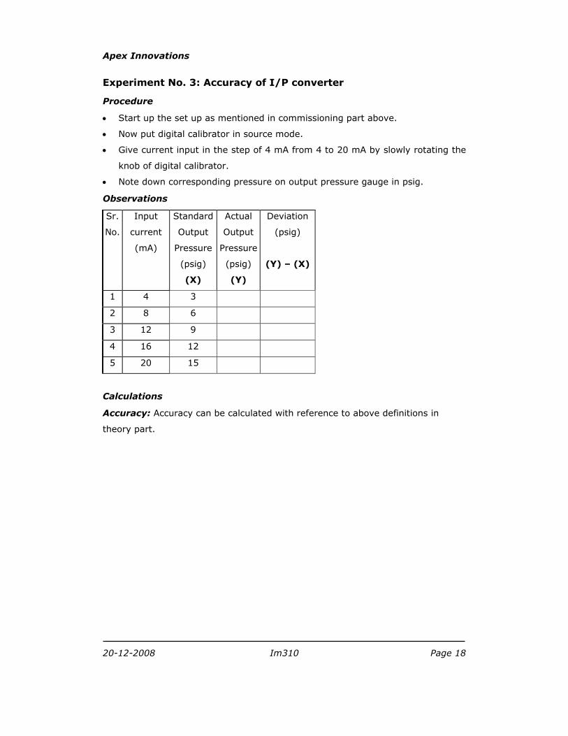
Experiment No. 3: Accuracy of I/P converter
Procedure
• Start up the set up as mentioned in commissioning part above.
• Now put digital calibrator in source mode.
• Give current input in the step of 4 mA from 4 to 20 mA by slowly rotating the
knob of digital calibrator.
• Note down corresponding pressure on output pressure gauge in psig.
Observations
Sr.
No.
Input
current
(mA)
Standard
Output
Pressure
(psig)
(X)
Actual
Output
Pressure
(psig)
(Y)
Deviation
(psig)
(Y) – (X)
1 4 3
2 8 6
3 12 9
4 16 12
5 20 15
Calculations
Accuracy: Accuracy can be calculated with reference to above definitions in
theory part.
Apex Innovations
20-12-2008 Im310 Page 19
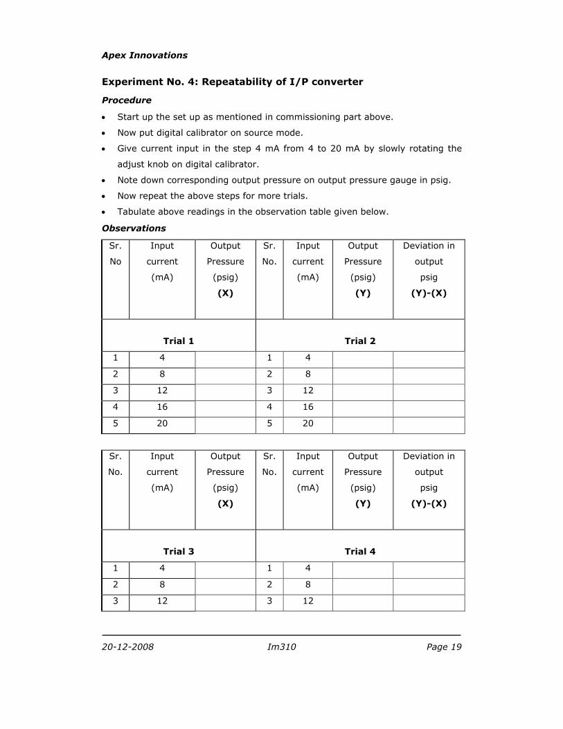
Experiment No. 4: Repeatability of I/P converter
Procedure
• Start up the set up as mentioned in commissioning part above.
• Now put digital calibrator on source mode.
• Give current input in the step 4 mA from 4 to 20 mA by slowly rotating the
adjust knob on digital calibrator.
• Note down corresponding output pressure on output pressure gauge in psig.
• Now repeat the above steps for more trials.
• Tabulate above readings in the observation table given below.
Observations
Sr.
No
Input
current
(mA)
Output
Pressure
(psig)
(X)
Sr.
No.
Input
current
(mA)
Output
Pressure
(psig)
(Y)
Deviation in
output
psig
(Y)-(X)
Trial 1
Trial 2
1 4 1 4
2 8 2 8
3 12 3 12
4 16 4 16
5 20 5 20
Sr.
No.
Input
current
(mA)
Output
Pressure
(psig)
(X)
Sr.
No.
Input
current
(mA)
Output
Pressure
(psig)
(Y)
Deviation in
output
psig
(Y)-(X)
Trial 3
Trial 4
1 4 1 4
2 8 2 8
3 12 3 12

Apex Innovations
20-12-2008 Im310 Page 20
4 16 4 16
5 20 5 20
Calculations
Repeatability: Note down the values of output for same input in repeated trials.
Repeatability can be found out in % of each reading.
Apex Innovations
20-12-2008 Im310 Page 21
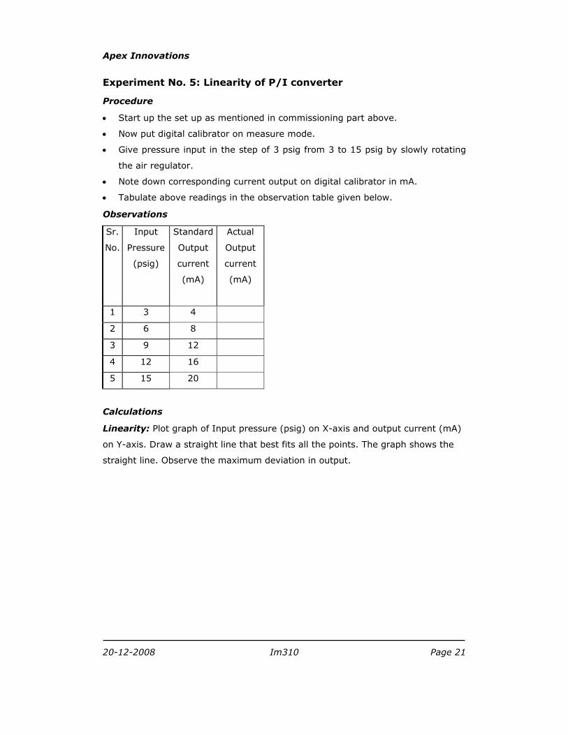
Experiment No. 5: Linearity of P/I converter
Procedure
• Start up the set up as mentioned in commissioning part above.
• Now put digital calibrator on measure mode.
• Give pressure input in the step of 3 psig from 3 to 15 psig by slowly rotating
the air regulator.
• Note down corresponding current output on digital calibrator in mA.
• Tabulate above readings in the observation table given below.
Observations
Sr.
No.
Input
Pressure
(psig)
Standard
Output
current
(mA)
Actual
Output
current
(mA)
1 3 4
2 6 8
3 9 12
4 12 16
5 15 20
Calculations
Linearity: Plot graph of Input pressure (psig) on X-axis and output current (mA)
on Y-axis. Draw a straight line that best fits all the points. The graph shows the
straight line. Observe the maximum deviation in output.
Apex Innovations
20-12-2008 Im310 Page 22
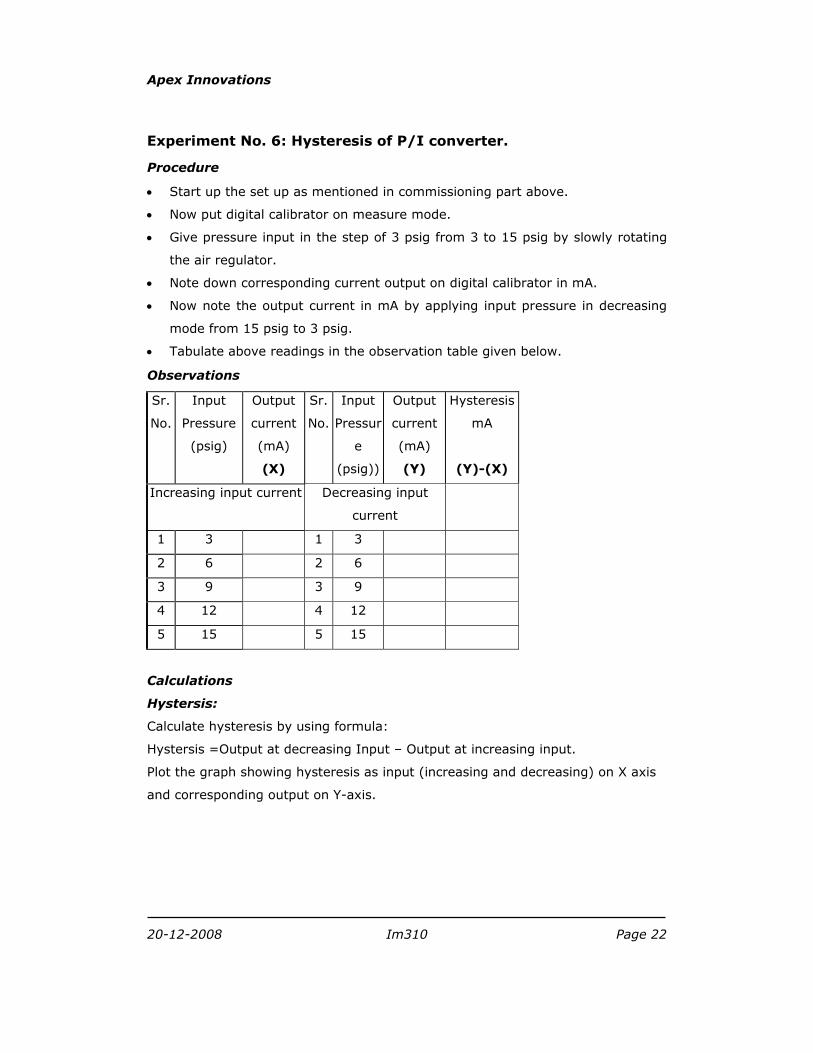
Experiment No. 6: Hysteresis of P/I converter.
Procedure
• Start up the set up as mentioned in commissioning part above.
• Now put digital calibrator on measure mode.
• Give pressure input in the step of 3 psig from 3 to 15 psig by slowly rotating
the air regulator.
• Note down corresponding current output on digital calibrator in mA.
• Now note the output current in mA by applying input pressure in decreasing
mode from 15 psig to 3 psig.
• Tabulate above readings in the observation table given below.
Observations
Sr.
No.
Input
Pressure
(psig)
Output
current
(mA)
(X)
Sr.
No.
Input
Pressur
e
(psig))
Output
current
(mA)
(Y)
Hysteresis
mA
(Y)-(X)
Increasing input current Decreasing input
current
1 3 1 3
2 6 2 6
3 9 3 9
4 12 4 12
5 15 5 15
Calculations
Hystersis:
Calculate hysteresis by using formula:
Hystersis =Output at decreasing Input – Output at increasing input.
Plot the graph showing hysteresis as input (increasing and decreasing) on X axis
and corresponding output on Y-axis.
Apex Innovations
20-12-2008 Im310 Page 23
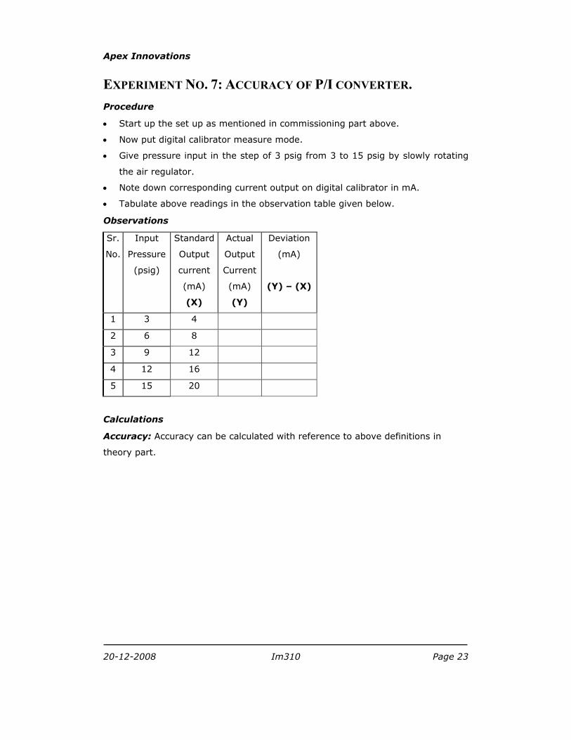
EXPERIMENT NO. 7: ACCURACY OF P/I CONVERTER. Procedure
• Start up the set up as mentioned in commissioning part above.
• Now put digital calibrator measure mode.
• Give pressure input in the step of 3 psig from 3 to 15 psig by slowly rotating
the air regulator.
• Note down corresponding current output on digital calibrator in mA.
• Tabulate above readings in the observation table given below.
Observations
Sr.
No.
Input
Pressure
(psig)
Standard
Output
current
(mA)
(X)
Actual
Output
Current
(mA)
(Y)
Deviation
(mA)
(Y) – (X)
1 3 4
2 6 8
3 9 12
4 12 16
5 15 20
Calculations
Accuracy: Accuracy can be calculated with reference to above definitions in
theory part.

Apex Innovations
20-12-2008 Im310 Page 24
Experiment No. 8: Repeatability of P/I converter
Procedure
• Start up the set up as mentioned in commissioning part above.
• Now put digital calibrator in measure mode.
• Give pressure input in the step of 3 psig from 3 to 15 psig by slowly rotating
the air regulator.
• Note down corresponding current output on digital calibrator in mA.
• Now repeat the above steps for more trials.
• Tabulate above readings in the observation table given below.
Observations
Sr.
No.
Input
current
(mA)
Output
Pressure
(psig)
(X)
Sr.
No.
Input
current
(mA)
Output
Pressure
(psig)
(Y)
Deviation
in output
psig
(Y)-(X)
Trial 1
Trial 2
1 3 1 3
2 6 2 6
3 9 3 9
4 12 4 12
5 15 5 15
Sr.
No.
Input
current
(mA)
Output
Pressure
(psig)
(X)
Sr.
No.
Input
current
(mA)
Output
Pressure
(psig)
(Y)
Deviation
in output
psig
(Y)-(X)
Trial 3
Trial 4
1 3 1 3
2 6 2 6
3 9 3 9

Apex Innovations
20-12-2008 Im310 Page 25
4 12 4 12
5 15 5 15
Calculations
Repeatability: Note down the values of output for same input in repeated trials.
Repeatability can be found out in % of each reading.
20-12-2008 Im310 Page 26
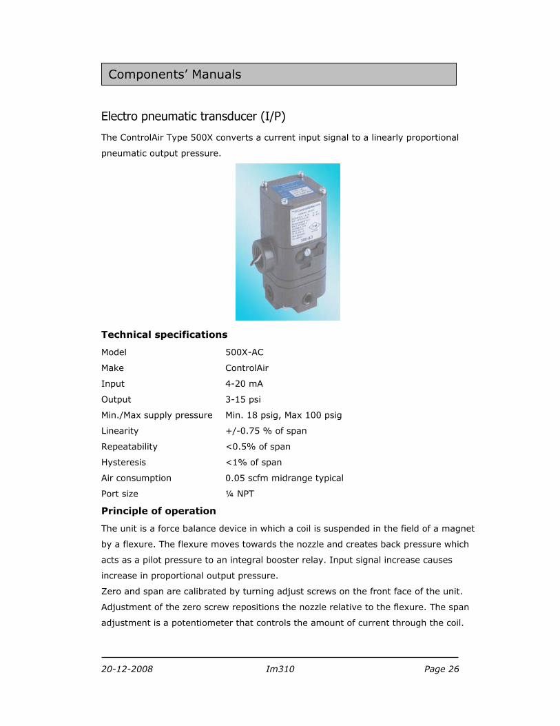
Electro pneumatic transducer (I/P)
The ControlAir Type 500X converts a current input signal to a linearly proportional
pneumatic output pressure.
Technical specifications
Model 500X-AC
Make ControlAir
Input 4-20 mA
Output 3-15 psi
Min./Max supply pressure Min. 18 psig, Max 100 psig
Linearity +/-0.75 % of span
Repeatability <0.5% of span
Hysteresis <1% of span
Air consumption 0.05 scfm midrange typical
Port size ¼ NPT
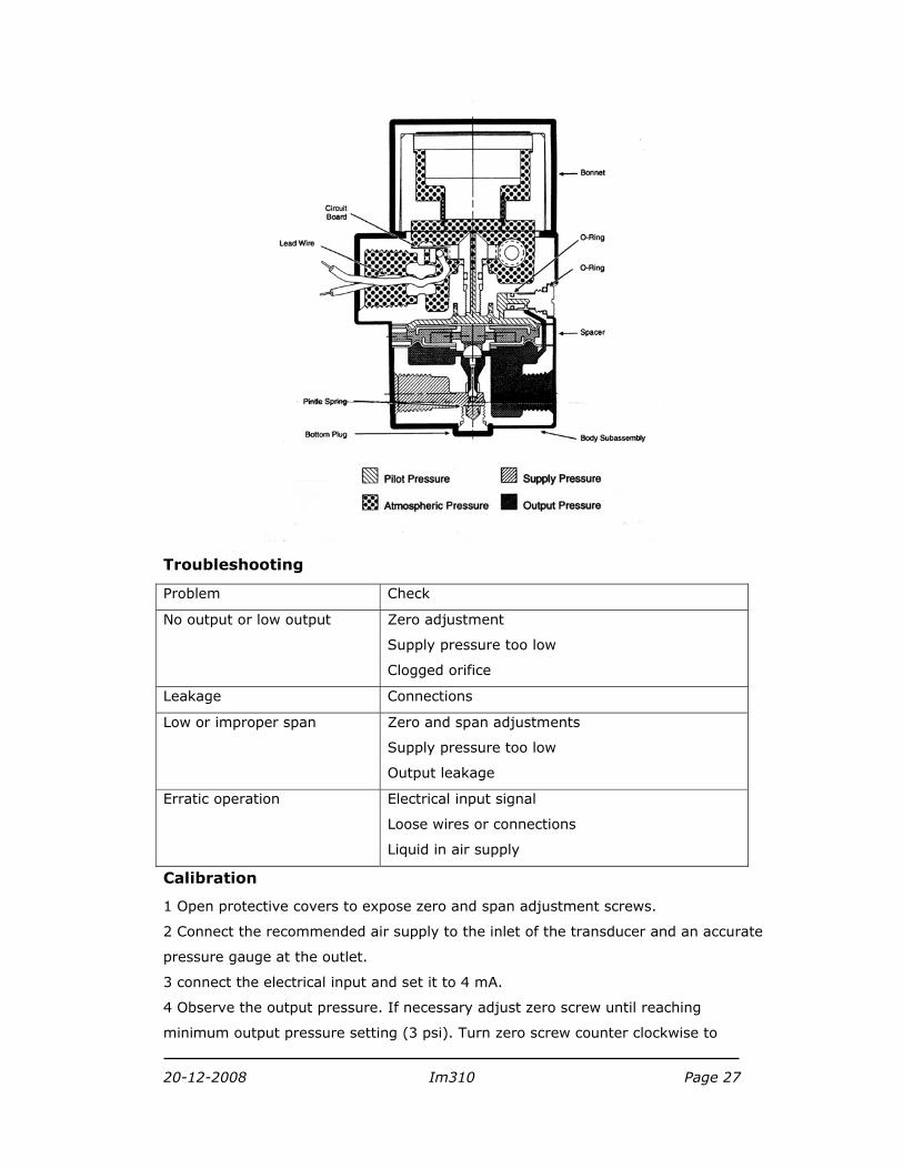
Principle of operation
The unit is a force balance device in which a coil is suspended in the field of a magnet
by a flexure. The flexure moves towards the nozzle and creates back pressure which
acts as a pilot pressure to an integral booster relay. Input signal increase causes
increase in proportional output pressure.
Zero and span are calibrated by turning adjust screws on the front face of the unit.
Adjustment of the zero screw repositions the nozzle relative to the flexure. The span
adjustment is a potentiometer that controls the amount of current through the coil.
Components’ Manuals
20-12-2008 Im310 Page 27
Troubleshooting
Problem Check
No output or low output Zero adjustment
Supply pressure too low
Clogged orifice
Leakage Connections
Low or improper span Zero and span adjustments
Supply pressure too low
Output leakage
Erratic operation Electrical input signal
Loose wires or connections
Liquid in air supply
Calibration
1 Open protective covers to expose zero and span adjustment screws.
2 Connect the recommended air supply to the inlet of the transducer and an accurate
pressure gauge at the outlet.
3 connect the electrical input and set it to 4 mA.
4 Observe the output pressure. If necessary adjust zero screw until reaching
minimum output pressure setting (3 psi). Turn zero screw counter clockwise to
20-12-2008 Im310 Page 28
increase pressure, clockwise to decrease pressure. If unable to achieve output
during calibration process, turn zero adjustment screw counter clockwise
for up to 30 revolutions, until output pressure rises.
5 Increase electrical input to 20 mA
6 Observe the output pressure. If necessary adjust the span screw until output
pressure reaching 15 psi. Turn span screw counter clockwise to increase pressure,
clockwise to decrease pressure.
7 The zero span adjustments are interactive. After adjusting the span it will be
necessary to recheck the zero. Repeat steps 3-6 until both end points are at the
required values.
Manufacturer’s address
Control Air Inc.
8 Columbia Drive, Amherst, NH 03031
USA
Email: [email protected]
Indian supplier:
Control teknics
5,Aboorva Flats, old No.6, New No. 11
7th main road, Raja Annamalaipuram
Chennai - 600 028
Email: [email protected]

20-12-2008 Im310 Page 29
Mini combination air filter regulator
These modular series filter regulator are high flow, low pressure, and high accuracy.
Technical specifications
Make Airmatic
Model MB10-021-VD-PAP
Range 0 – 2 Kg/cm2
Type Diaphragm, Relieving
Connection ¼”BSP
Body Aluminium
Bowl Polycarbonate
Element Porous material
Drain Brass
Seals Buna – N
Diaphragm Buna – N
Spring pressure Spring steel Zn plated
Spring valve Stainless steel
Spring cage and nob Acetyl resin
Gauge ports Two
Element rating 25 micron
Drain Manual
Bowl capacity 30 ml
Max. pressure 12kg/cm2
Max. temperature 500C
Overall dimensions 40diameter x 155 H mm
Weight 220 gm

20-12-2008 Im310 Page 30
Manufacturer’s address
Shah pneumatics, 28/30, Navketan Industrial Estate,
Mahakali Caves Road, Andheri (E), Mumbai – 400 093.
E-mail: [email protected] Web: www.shahpneumatics.com