Embed Size (px)
Citation preview

2011
AIM
MA
NU
AL
FRA
NK
LIN
ELE
CTR
IC
SUBMERSIBLE MOTORSAPPLICATION | INSTALLATION | MAINTENANCE60 Hz, Single-Phase and Three-Phase Motors
AIM MANUAL
2015 EDITION
franklinwater.com

FRANKLIN ELECTRIC GLOBAL HEADQUARTERS & ENGINEERING DEVELOPMENT CENTER, FORT WAYNE, INDIANA
COMMITMENT TO QUALITYFranklin Electric is committed to provide customers with defect free products through our program of continuous improvement. Quality shall, in every case, take precedence over quantity.
ATTENTION!IMPORTANT INFORMATION FOR INSTALLERS OF THIS EQUIPMENT!
THIS EQUIPMENT IS INTENDED FOR INSTALLATION BY TECHNICALLY QUALIFIED PERSONNEL. FAILURE TO INSTALL IT IN COMPLIANCE WITH NATIONAL AND LOCAL ELECTRICAL CODES, AND WITHIN FRANKLIN ELECTRIC RECOMMENDATIONS, MAY RESULT IN ELECTRICAL SHOCK OR FIRE HAZARD, UNSATISFACTORY
PERFORMANCE, AND EQUIPMENT FAILURE. FRANKLIN INSTALLATION INFORMATION IS AVAILABLE FROM PUMP MANUFACTURERS AND DISTRIBUTORS, AND DIRECTLY FROM FRANKLIN ELECTRIC. CALL FRANKLIN TOLL FREE 800-348-2420 FOR INFORMATION.
WARNINGSERIOUS OR FATAL ELECTRICAL SHOCK MAY RESULT FROM FAILURE TO CONNECT THE MOTOR, CONTROL ENCLOSURES, METAL PLUMBING, AND ALL OTHER METAL NEAR THE MOTOR OR CABLE, TO THE POWER SUPPLY GROUND TERMINAL USING WIRE NO SMALLER THAN MOTOR CABLE WIRES. TO REDUCE RISK
OF ELECTRICAL SHOCK, DISCONNECT POWER BEFORE WORKING ON OR AROUND THE WATER SYSTEM. DO NOT USE MOTOR IN SWIMMING AREAS.
ATTENTION!INFORMATIONS IMPORTANTES POUR L’INSTALLATEUR DE CET EQUIPEMENT.
CET EQUIPEMENT DOIT ETRE INTALLE PAR UN TECHNICIEN QUALIFIE. SI L’INSTALLATION N’EST PAS CONFORME AUX LOIS NATIONALES OU LOCALES AINSI QU’AUX RECOMMANDATIONS DE FRANKLIN ELECTRIC, UN CHOC ELECTRIQUE, LE FEU, UNE PERFORMANCE NON ACCEPTABLE, VOIRE MEME LE NON-
FONCTIONNEMENT PEUVENT SURVENIR. UN GUIDE D’INSTALLATION DE FRANKLIN ELECTRIC EST DISPONIBLE CHEZ LES MANUFACTURIERS DE POMPES, LES DISTRIBUTEURS, OU DIRECTEMENT CHEZ FRANKLIN. POUR DE PLUS AMPLES RENSEIGNEMENTS, APPELEZ SANS FRAIS LE 800-348-2420.
AVERTISEMENTUN CHOC ELECTRIQUE SERIEUX OU MEME MORTEL EST POSSIBLE, SI L’ON NEGLIGE DE CONNECTER LE MOTEUR, LA PLOMBERIE METALLIQUE, BOITES DE
CONTROLE ET TOUT METAL PROCHE DU MOTEUR A UN CABLE ALLANT VERS UNE ALIMENTATION D’ENERGIE AVEC BORNE DE MISE A LA TERRE UTILISANT AU MOINS LE MEME CALIBRE QUE LES FILS DU MOTEUR. POUR REDUIRE LE RISQUE DE CHOC ELECTRIQUE. COUPER LE COURANT AVANT DE TRAVAILLER
PRES OU SUR LE SYSTEM D’EAU. NE PAS UTILISER CE MOTEUR DANS UNE ZONE DE BAIGNADE.
ATENCION!INFORMACION PARA EL INSTALADOR DE ESTE EQUIPO.
PARA LA INSTALACION DE ESTE EQUIPO, SE REQUIERE DE PERSONAL TECNICO CALIFICADO. EL NO CUMPLIR CON LAS NORMAS ELECTRICAS NACIONALES Y LOCALES, ASI COMO CON LAS RECOMENDACIONES DE FRANKLIN ELECTRIC DURANTE SU INSTALACION, PUEDE OCASIONAR, UN CHOQUE ELECTRICO,
PELIGRO DE UN INCENDIO, OPERACION DEFECTUOSA E INCLUSO LA DESCOMPOSTURA DEL EQUIPO. LOS MANUALES DE INSTALACION Y PUESTA EN MARCHA DE LOS EQUIPOS, ESTAN DISPONIBLES CON LOS DISTRIBUIDORES, FABRICANTES DE BOMBAS O DIRECTAMENTE CON FRANKLIN ELECTRIC. PUEDE
LLAMAR GRATUITAMENTE PARA MAYOR INFORMACION AL TELEFONO 800-348-2420.
ADVERTENCIAPUEDE OCURRIR UN CHOQUE ELECTRICO, SERIO O FATAL DEBIDO A UNA ERRONEA CONECCION DEL MOTOR, DE LOS TABLEROS ELECTRICOS, DE LA TUBERIA,
DE CUALQUIER OTRA PARTE METALICA QUE ESTA CERCA DEL MOTOR O POR NO UTILIZAR UN CABLE PARA TIERRA DE CALIBRE IGUAL O MAYOR AL DE LA ALIMENTACION. PARA REDUCIR EL RIESGO DE CHOQUE ELECTRIC, DESCONECTAR LA ALIMENTACION ELECTRICA ANTES DE INICIAR A TRABAJAR EN EL
SISTEMA HIDRAULICO. NO UTILIZAR ESTE MOTOR EN ALBERCAS O AREAS EN DONDE SE PRACTIQUE NATACION.

Contents
The submersible motor is a reliable, efficient and trouble-free means of powering a pump. Its needs for a long operational life are simple. They are:
1. A suitable operating environment2. An adequate supply of electricity3. An adequate flow of cooling water over the motor4. An appropriate pump load
All considerations of application, installation, and maintenance of submersible motors relating to these four areas are presented in this manual. Franklin Electric’s web page, www.franklin-electric.com, should be checked for the latest updates.
Application • Installation • Maintenance Manual
Application
Installation
Maintenance
All MotorsStorage................................................................................................................................................3Frequency of Starts ............................................................................................................................3Mounting Position ..............................................................................................................................3Transformer Capacity ........................................................................................................................ 4Effects of Torque ............................................................................................................................... 4Use of Engine Driven Generators ......................................................................................................5Use of Check Valves ...........................................................................................................................5Well Diameters, Uncased, Top Feeding, Screens ............................................................................ 6Water Temperature and Flow .......................................................................................................... 6Flow Inducer Sleeve .......................................................................................................................... 6
Pumptec ProductsHead Loss Past Motor.........................................................................................................................7Hot Water Applications ................................................................................................................. 7-8Drawdown Seals ............................................................................................................................... 9Grounding Control Boxes and Panels .............................................................................................. 9Grounding Surge Arrestors............................................................................................................... 9Control Box, Pumptec Products and Panel Environment .............................................................. 9Equipment Grounding ...................................................................................................................... 9
Single-Phase Motors3-Wire Control Boxes ....................................................................................................................... 102-Wire Motor Solid State Controls................................................................................................... 10QD Relays (Solid State) .................................................................................................................... 10Cable Selection 2-Wire or 3-Wire .................................................................................................... 11Two Different Cable Sizes ................................................................................................................ 12Single-Phase Motor Specifications ................................................................................................. 13 Single-Phase Motor Fuse Sizing...................................................................................................... 14Auxiliary Running Capacitors .......................................................................................................... 15Buck-Boost Transformers ................................................................................................................ 15
All MotorsSubmersible Motors - Dimensions .................................................................................................42Tightening Lead Connector Jam Nut ..............................................................................................43Pump to Motor Coupling .................................................................................................................43
All MotorsSystem Troubleshooting ............................................................................................................44-45Preliminary Tests ............................................................................................................................. 46Insulation Resistance .................................................................................................................46-47Resistance of Drop Cable ...........................................................................................................46-47
Single-Phase Motors and ControlsIdentification of Cables................................................................................................................... 48Single-Phase Control Boxes ........................................................................................................... 48Ohmmeter Tests .............................................................................................................................. 49QD Control Box Parts ....................................................................................................................... 50
Integral hp Control Box Parts .....................................................................................................51-52Control Box Wiring Diagrams .................................................................................................... 53-57
Electronic ControlsPumptec-Plus Troubleshooting During Installation...................................................................... 61Pumptec-Plus and Pumptec After Installation .............................................................................62QD Pumptec and Pumptec Troubleshooting .................................................................................63SubDrive/MonoDrive Troubleshooting .................................................................................... 64-69SubMonitor Troubleshooting ..........................................................................................................70Abbreviations ................................................................................................................................... 71
Pump to Motor Assembly................................................................................................................43 Shaft Height and Free End Play ......................................................................................................43Submersible Leads and Cables .......................................................................................................43
Three-Phase MotorsCable Selection - 60 °C Three-Wire ............................................................................................16-17 Cable Selection - 60 °C Six-Wire ..................................................................................................... 18Cable Selection - 75 °C Three-Wire ........................................................................................... 19-20 Cable Selection - 75 °C Six-Wire...................................................................................................... 21Three-Phase Motor Specifications ............................................................................................ 22-28 Overload Protection ....................................................................................................................29-31
Submersible Motor Installation Record (Action Facts) Submersible Motor Installation Record (No. 2207) Submersible Booster Installation Record (No. 3655)
SubMonitor .......................................................................................................................................32Power Factor Correction ..................................................................................................................32Three-Phase Starter Diagrams .......................................................................................................33Three-Phase Power Unbalance.......................................................................................................34Rotation and Current Unbalance ....................................................................................................34Three-Phase Motor Lead Identification ..........................................................................................35Phase Converters .............................................................................................................................35Reduced Voltage Starters ................................................................................................................36Inline Booster Pump Systems ................................................................................................... 36-39Variable Speed Operation ......................................................................................................... 40-41
Electronic Products
SubDrive/MonoDrive Overview ......................................................................................................58SubDrive/MonoDrive Generator Sizing ..........................................................................................58SubDrive/MonoDrive Ground Wire Location ..................................................................................58SubDrive/MonoDrive Fuse/Circuit Breaker Sizing .........................................................................59SubDrive/MonoDrive Wire Sizing ...................................................................................................59 SubDrive/MonoDrive Pressure Tank Sizing ................................................................................... 60SubDrive/MonoDrive Pressure Tank Pre-Charge .......................................................................... 60
60 Hz, Single-Phase and Three-PhaseSUBMERSIBLE MOTOR
All MotorsAPPLICATION
Franklin submersible motors are designed primarily for operation in the vertical, shaft-up position.
During acceleration, the pump thrust increases as its output head increases. In cases where the pump head stays below its normal operating range during startup and full speed condition, the pump may create upward thrust. This creates upward thrust on the motor upthrust bearing. This is an acceptable operation for short periods at each start, but running continuously with upthrust will cause excessive wear on the upthrust bearing.
With certain additional restrictions as listed in this section and the Inline Booster Pump Systems sections of this manual, motors are also suitable for operation in positions from shaft-up to shaft-horizontal. As the mounting position becomes further from vertical and closer to horizontal, the probability of shortened thrust bearing life increases. For normal motor life expectancy with motor positions other than shaft-up, follow these recommendations:
Franklin Electric submersible motors are a water-lubricated design. The fill solution consists of a mixture of deionized water and Propylene Glycol (a non-toxic antifreeze). The solution will prevent damage from freezing in temperatures to -40 °F (-40 °C); motors should be stored in areas that do not go below this temperature. The solution will partially freeze below 27 °F (-3 °C), but no damage occurs. Repeated freezing and thawing should be avoided to prevent possible loss of fill solution.
There may be an interchange of fill solution with well water during operation. Care must be taken with motors removed from wells during freezing conditions to prevent damage.
When the storage temperature does not exceed 100 °F (37 °C), storage time should be limited to two years. Where temperatures reach 100° to 130 °F, storage time should be limited to one year.
Loss of a few drops of liquid will not damage the motor as an excess amount is provided, and the filter check valve will allow lost liquid to be replaced by filtered well water upon installation. If there is reason to believe there has been a considerable amount of leakage, consult the factory for checking procedures.
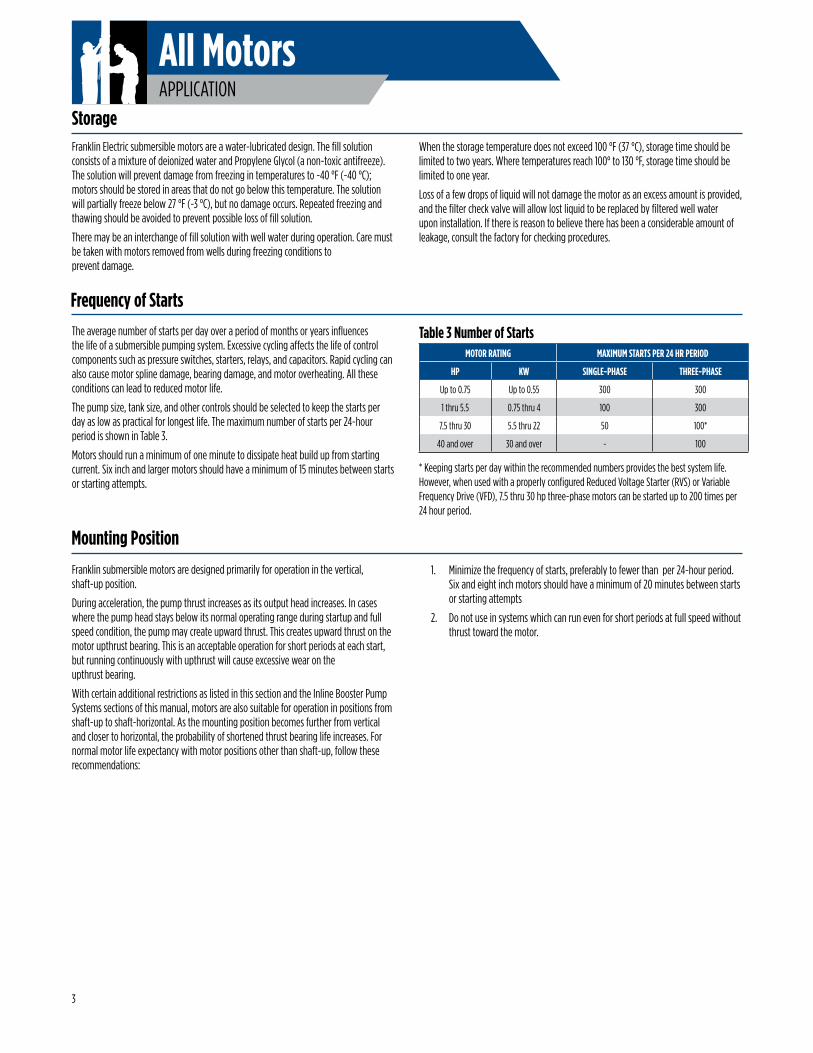
The average number of starts per day over a period of months or years influences the life of a submersible pumping system. Excessive cycling affects the life of control components such as pressure switches, starters, relays, and capacitors. Rapid cycling can also cause motor spline damage, bearing damage, and motor overheating. All these conditions can lead to reduced motor life.
The pump size, tank size, and other controls should be selected to keep the starts per day as low as practical for longest life. The maximum number of starts per 24-hour period is shown in Table 3.
Motors should run a minimum of one minute to dissipate heat build up from starting current. Six inch and larger motors should have a minimum of 15 minutes between starts or starting attempts.
1. Minimize the frequency of starts, preferably to fewer than per 24-hour period. Six and eight inch motors should have a minimum of 20 minutes between starts or starting attempts
2. Do not use in systems which can run even for short periods at full speed without thrust toward the motor.
Storage
Frequency of Starts
Mounting Position
MOTOR RATING MAXIMUM STARTS PER 24 HR PERIOD
HP KW SINGLE-PHASE THREE-PHASE
Up to 0.75 Up to 0.55 300 300
1 thru 5.5 0.75 thru 4 100 300
7.5 thru 30 5.5 thru 22 50 100*
40 and over 30 and over - 100
Table 3 Number of Starts
* Keeping starts per day within the recommended numbers provides the best system life. However, when used with a properly configured Reduced Voltage Starter (RVS) or Variable Frequency Drive (VFD), 7.5 thru 30 hp three-phase motors can be started up to 200 times per 24 hour period.
3
All MotorsAPPLICATION
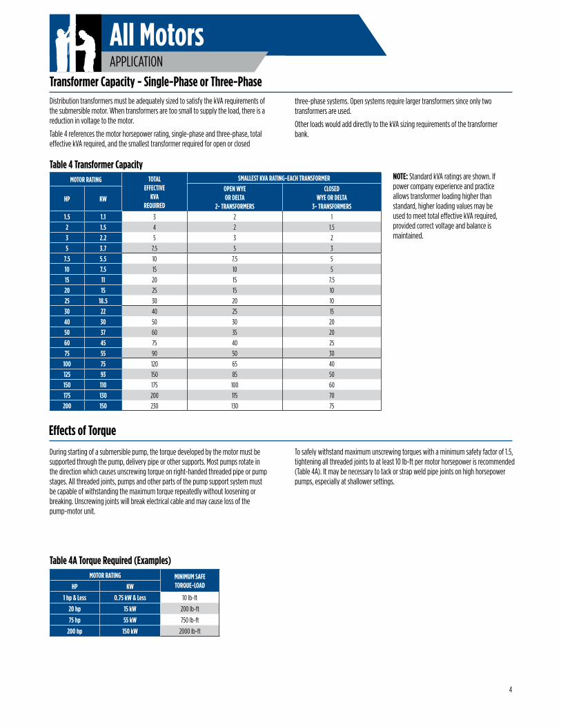
Distribution transformers must be adequately sized to satisfy the kVA requirements of the submersible motor. When transformers are too small to supply the load, there is a reduction in voltage to the motor.
Table 4 references the motor horsepower rating, single-phase and three-phase, total effective kVA required, and the smallest transformer required for open or closed
Transformer Capacity - Single-Phase or Three-Phase
NOTE: Standard kVA ratings are shown. If power company experience and practice allows transformer loading higher than standard, higher loading values may be used to meet total effective kVA required, provided correct voltage and balance is maintained.
three-phase systems. Open systems require larger transformers since only two transformers are used.
Other loads would add directly to the kVA sizing requirements of the transformer bank.
During starting of a submersible pump, the torque developed by the motor must be supported through the pump, delivery pipe or other supports. Most pumps rotate in the direction which causes unscrewing torque on right-handed threaded pipe or pump stages. All threaded joints, pumps and other parts of the pump support system must be capable of withstanding the maximum torque repeatedly without loosening or breaking. Unscrewing joints will break electrical cable and may cause loss of the pump-motor unit.
To safely withstand maximum unscrewing torques with a minimum safety factor of 1.5, tightening all threaded joints to at least 10 lb-ft per motor horsepower is recommended (Table 4A). It may be necessary to tack or strap weld pipe joints on high horsepower pumps, especially at shallower settings.
Effects of Torque
Table 4A Torque Required (Examples)
MOTOR RATING TOTALEFFECTIVE
KVAREQUIRED
SMALLEST KVA RATING-EACH TRANSFORMEROPEN WYEOR DELTA
2- TRANSFORMERS
CLOSED WYE OR DELTA
3- TRANSFORMERSHP KW
1.5 1.1 3 2 1
2 1.5 4 2 1.5
3 2.2 5 3 2
5 3.7 7.5 5 3
7.5 5.5 10 7.5 5
10 7.5 15 10 5
15 11 20 15 7.5
20 15 25 15 10
25 18.5 30 20 10
30 22 40 25 15
40 30 50 30 20
50 37 60 35 20
60 45 75 40 25
75 55 90 50 30
100 75 120 65 40
125 93 150 85 50
150 110 175 100 60
175 130 200 115 70
200 150 230 130 75
Table 4 Transformer Capacity
MOTOR RATING MINIMUM SAFE TORQUE-LOAD HP KW
1 hp & Less 0.75 kW & Less 10 lb-ft
20 hp 15 kW 200 lb-ft
75 hp 55 kW 750 lb-ft
200 hp 150 kW 2000 lb-ft
4
All MotorsAPPLICATION
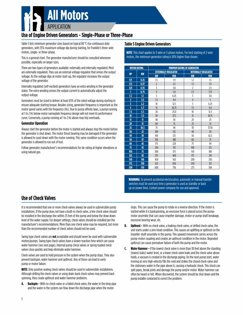
WARNING: To prevent accidental electrocution, automatic or manual transfer switches must be used any time a generator is used as standby or back up on power lines. Contact power company for use and approval.
Table 5 lists minimum generator sizes based on typical 80 °C rise continuous duty generators, with 35% maximum voltage dip during starting, for Franklin’s three-wire motors, single- or three-phase.
This is a general chart. The generator manufacturer should be consulted whenever possible, especially on larger sizes.
There are two types of generators available: externally and internally regulated. Most are externally regulated. They use an external voltage regulator that senses the output voltage. As the voltage dips at motor start-up, the regulator increases the output voltage of the generator.
Internally regulated (self-excited) generators have an extra winding in the generator stator. The extra winding senses the output current to automatically adjust the output voltage.
Generators must be sized to deliver at least 65% of the rated voltage during starting to ensure adequate starting torque. Besides sizing, generator frequency is important as the motor speed varies with the frequency (Hz). Due to pump affinity laws, a pump running at 1 to 2 Hz below motor nameplate frequency design will not meet its performance curve. Conversely, a pump running at 1 to 2 Hz above may trip overloads.
Generator Operation Always start the generator before the motor is started and always stop the motor before the generator is shut down. The motor thrust bearing may be damaged if the generator is allowed to coast down with the motor running. This same condition occurs when the generator is allowed to run out of fuel.
Follow generator manufacturer’s recommendations for de-rating at higher elevations or using natural gas.
It is recommended that one or more check valves always be used in submersible pump installations. If the pump does not have a built-in check valve, a line check valve should be installed in the discharge line within 25 feet of the pump and below the draw down level of the water supply. For deeper settings, check valves should be installed per the manufacturer’s recommendations. More than one check valve may be required, but more than the recommended number of check valves should not be used.
Swing type check valves are not acceptable and should never be used with submersible motors/pumps. Swing type check valves have a slower reaction time which can cause water hammer (see next page). Internal pump check valves or spring loaded check valves close quickly and help eliminate water hammer.
Check valves are used to hold pressure in the system when the pump stops. They also prevent backspin, water hammer and upthrust. Any of these can lead to early pump or motor failure.
NOTE: Only positive sealing check valves should be used in submersible installations. Although drilling the check valves or using drain-back check valves may prevent back spinning, they create upthrust and water hammer problems.
A. Backspin - With no check valve or a failed check valve, the water in the drop pipe and the water in the system can flow down the discharge pipe when the motor
stops. This can cause the pump to rotate in a reverse direction. If the motor is started while it is backspinning, an excessive force is placed across the pump-motor assembly that can cause impeller damage, motor or pump shaft breakage, excessive bearing wear, etc.
B. Upthrust - With no check valve, a leaking check valve, or drilled check valve, the unit starts under a zero head condition. This causes an uplifting or upthrust on the impeller-shaft assembly in the pump. This upward movement carries across the pump-motor coupling and creates an upthrust condition in the motor. Repeated upthrust can cause premature failure of both the pump and the motor.
C. Water Hammer - If the lowest check valve is more than 30 feet above the standing (lowest static) water level, or a lower check valve leaks and the check valve above holds, a vacuum is created in the discharge piping. On the next pump start, water moving at very high velocity fills the void and strikes the closed check valve and the stationary water in the pipe above it, causing a hydraulic shock. This shock can split pipes, break joints and damage the pump and/or motor. Water hammer can often be heard or felt. When discovered, the system should be shut down and the pump installer contacted to correct the problem.
Use of Engine Driven Generators - Single-Phase or Three-PhaseTable 5 Engine Driven Generators
MOTOR RATING MINIMUM RATING OF GENERATOR
HP KWEXTERNALLY REGULATED INTERNALLY REGULATEDKW KVA KW KVA
1/3 0.25 1.5 1.9 1.2 1.51/2 0.37 2 2.5 1.5 1.93/4 0.55 3 3.8 2 2.5
1 0.75 4 5.0 2.5 3.131.5 1.1 5 6.25 3 3.82 1.5 7.5 9.4 4 53 2.2 10 12.5 5 6.255 3.7 15 18.75 7.5 9.4
7.5 5.5 20 25.0 10 12.510 7.5 30 37.5 15 18.7515 11 40 50 20 2520 15 60 75 25 3125 18.5 75 94 30 37.5030 22 100 125 40 5040 30 100 125 50 62.550 37 150 188 60 7560 45 175 220 75 9475 55 250 313 100 125
100 75 300 375 150 188125 93 375 469 175 219150 110 450 563 200 250175 130 525 656 250 313200 150 600 750 275 344
Use of Check Valves
NOTE: This chart applies to 3-wire or 3-phase motors. For best starting of 2-wire motors, the minimum generator rating is 50% higher than shown.
5
All MotorsAPPLICATION
Franklin Electric submersible motors are designed to operate with a cooling flow of water over and around the full length of the motor.
If the pump installation does not provide the minimum flow shown in Table 6, a flow inducer sleeve (flow sleeve) must be used. The conditions requiring a flow sleeve are:
Wells – Large Diameter, Uncased, Top Feeding and Screened Sections• Well diameter is too large to meet Table 6 flow requirements
• Pump is in an open body of water
• Pump is in a rock well or below the well casing
• The well is “top-feeding” (a.k.a. cascading)
• Pump is set in or below screens or perforations
Franklin Electric’s standard submersible motors, except Hi-Temp designs (see note below), are designed to operate up to maximum service factor horsepower in water up to 86 °F (30 °C). A flow of 0.25 ft/s for 4" motors rated 3 hp and higher, and 0.5 ft/s for 6" and 8" motors is required for proper cooling. Table 6 shows minimum flow rates, in gpm, for various well diameters and motor sizes.
If a standard motor is operated in water over 86 °F (30 °C), water flow past the motor must be increased to maintain safe motor operating temperatures. See HOT WATER APPLICATIONS on page 7.
NOTE: Franklin Electric offers a line of Hi-Temp motors designed to operate in water at higher temperatures or lower flow conditions. Consult factory for details.
Water Temperature and Flow
0.25 ft/s = 7.62 cm/sec 0.50 ft/s = 15.24 cm/sec 1 inch = 2.54 cm
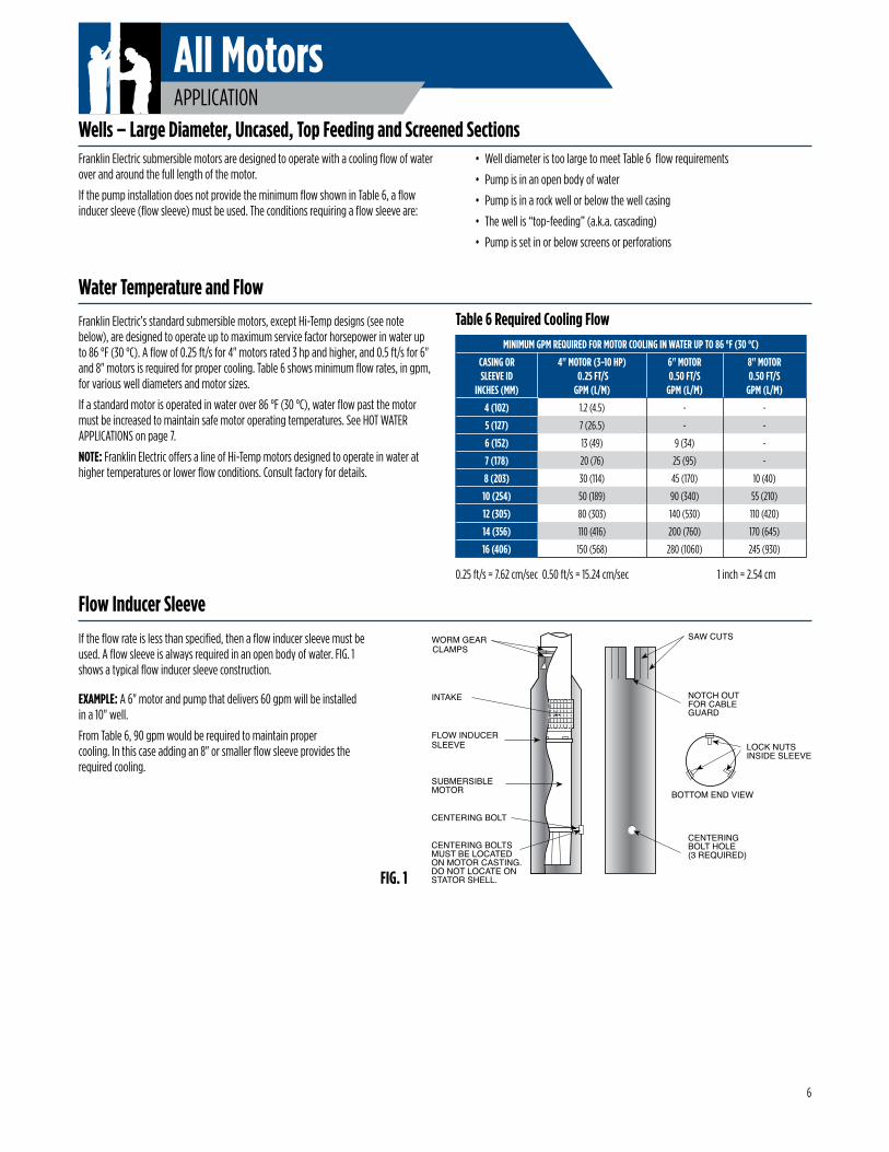
If the flow rate is less than specified, then a flow inducer sleeve must be used. A flow sleeve is always required in an open body of water. FIG. 1 shows a typical flow inducer sleeve construction.
EXAMPLE: A 6" motor and pump that delivers 60 gpm will be installed in a 10" well.
From Table 6, 90 gpm would be required to maintain proper cooling. In this case adding an 8" or smaller flow sleeve provides the required cooling.
FIG. 1
WORM GEARCLAMPS
INTAKE
FLOW INDUCERSLEEVE
SUBMERSIBLEMOTOR
CENTERING BOLT
LOCK NUTS INSIDE SLEEVE
CENTERINGBOLT HOLE(3 REQUIRED)
BOTTOM END VIEW
NOTCH OUTFOR CABLEGUARD
SAW CUTS
CENTERING BOLTSMUST BE LOCATEDON MOTOR CASTING.DO NOT LOCATE ONSTATOR SHELL.
Table 6 Required Cooling FlowMINIMUM GPM REQUIRED FOR MOTOR COOLING IN WATER UP TO 86 °F (30 °C)
CASING ORSLEEVE ID
INCHES (MM)
4" MOTOR (3-10 HP) 0.25 FT/S
GPM (L/M)
6" MOTOR0.50 FT/S
GPM (L/M)
8" MOTOR0.50 FT/S
GPM (L/M)
4 (102) 1.2 (4.5) - -
5 (127) 7 (26.5) - -
6 (152) 13 (49) 9 (34) -
7 (178) 20 (76) 25 (95) -
8 (203) 30 (114) 45 (170) 10 (40)
10 (254) 50 (189) 90 (340) 55 (210)
12 (305) 80 (303) 140 (530) 110 (420)
14 (356) 110 (416) 200 (760) 170 (645)
16 (406) 150 (568) 280 (1060) 245 (930)
Flow Inducer Sleeve
6
All MotorsAPPLICATION
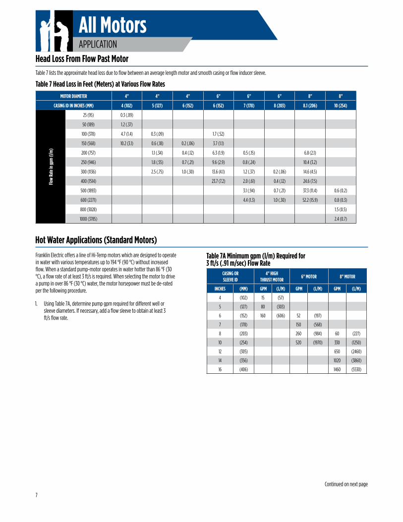
Table 7 lists the approximate head loss due to flow between an average length motor and smooth casing or flow inducer sleeve.
Head Loss From Flow Past Motor
Hot Water Applications (Standard Motors)Franklin Electric offers a line of Hi-Temp motors which are designed to operate in water with various temperatures up to 194 °F (90 °C) without increased flow. When a standard pump-motor operates in water hotter than 86 °F (30 °C), a flow rate of at least 3 ft/s is required. When selecting the motor to drive a pump in over 86 °F (30 °C) water, the motor horsepower must be de-rated per the following procedure.
1. Using Table 7A, determine pump gpm required for different well or sleeve diameters. If necessary, add a flow sleeve to obtain at least 3 ft/s flow rate.
MOTOR DIAMETER 4" 4" 4" 6" 6" 6" 8" 8"
CASING ID IN INCHES (MM) 4 (102) 5 (127) 6 (152) 6 (152) 7 (178) 8 (203) 8.1 (206) 10 (254)
Flow
Rate
in gp
m (l/
m)
25 (95) 0.3 (.09)
50 (189) 1.2 (.37)
100 (378) 4.7 (1.4) 0.3 (.09) 1.7 (.52)
150 (568) 10.2 (3.1) 0.6 (.18) 0.2 (.06) 3.7 (1.1)
200 (757) 1.1 (.34) 0.4 (.12) 6.3 (1.9) 0.5 (.15) 6.8 (2.1)
250 (946) 1.8 (.55) 0.7 (.21) 9.6 (2.9) 0.8 (.24) 10.4 (3.2)
300 (1136) 2.5 (.75) 1.0 (.30) 13.6 (4.1) 1.2 (.37) 0.2 (.06) 14.6 (4.5)
400 (1514) 23.7 (7.2) 2.0 (.61) 0.4 (.12) 24.6 (7.5)
500 (1893) 3.1 (.94) 0.7 (.21) 37.3 (11.4) 0.6 (0.2)
600 (2271) 4.4 (1.3) 1.0 (.30) 52.2 (15.9) 0.8 (0.3)
800 (3028) 1.5 (0.5)
1000 (3785) 2.4 (0.7)
Table 7 Head Loss in Feet (Meters) at Various Flow Rates
CASING ORSLEEVE ID
4" HIGH THRUST MOTOR
6" MOTOR 8" MOTOR
INCHES (MM) GPM (L/M) GPM (L/M) GPM (L/M)
4 (102) 15 (57)
5 (127) 80 (303)
6 (152) 160 (606) 52 (197)
7 (178) 150 (568)
8 (203) 260 (984) 60 (227)
10 (254) 520 (1970) 330 (1250)
12 (305) 650 (2460)
14 (356) 1020 (3860)
16 (406) 1460 (5530)
Table 7A Minimum gpm (l/m) Required for 3 ft/s (.91 m/sec) Flow Rate
7
Continued on next page
All MotorsAPPLICATION
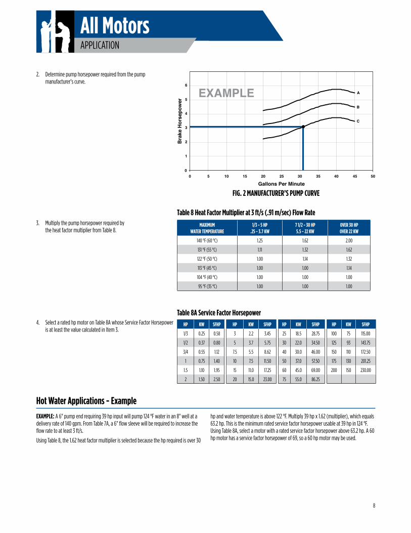
EXAMPLE: A 6" pump end requiring 39 hp input will pump 124 °F water in an 8" well at a delivery rate of 140 gpm. From Table 7A, a 6" flow sleeve will be required to increase the flow rate to at least 3 ft/s.
Using Table 8, the 1.62 heat factor multiplier is selected because the hp required is over 30
3. Multiply the pump horsepower required by the heat factor multiplier from Table 8.
4. Select a rated hp motor on Table 8A whose Service Factor Horsepower is at least the value calculated in Item 3.
Hot Water Applications - Examplehp and water temperature is above 122 °F. Multiply 39 hp x 1.62 (multiplier), which equals 63.2 hp. This is the minimum rated service factor horsepower usable at 39 hp in 124 °F. Using Table 8A, select a motor with a rated service factor horsepower above 63.2 hp. A 60 hp motor has a service factor horsepower of 69, so a 60 hp motor may be used.
Table 8 Heat Factor Multiplier at 3 ft/s (.91 m/sec) Flow Rate
Table 8A Service Factor Horsepower
2. Determine pump horsepower required from the pump manufacturer’s curve.
FIG. 2 MANUFACTURER’S PUMP CURVE
00 5 10 15 20 25 30 35 40 45 50
Gallons Per MinuteB
rake
Hor
sepo
wer
1
2
3
4
5
6
A
B
C
EXAMPLE
MAXIMUMWATER TEMPERATURE
1/3 - 5 HP.25 - 3.7 KW
7 1/2 - 30 HP5.5 - 22 KW
OVER 30 HPOVER 22 KW
140 °F (60 °C) 1.25 1.62 2.00
131 °F (55 °C) 1.11 1.32 1.62
122 °F (50 °C) 1.00 1.14 1.32
113 °F (45 °C) 1.00 1.00 1.14
104 °F (40 °C) 1.00 1.00 1.00
95 °F (35 °C) 1.00 1.00 1.00
HP KW SFHP HP KW SFHP HP KW SFHP HP KW SFHP
1/3 0.25 0.58 3 2.2 3.45 25 18.5 28.75 100 75 115.00
1/2 0.37 0.80 5 3.7 5.75 30 22.0 34.50 125 93 143.75
3/4 0.55 1.12 7.5 5.5 8.62 40 30.0 46.00 150 110 172.50
1 0.75 1.40 10 7.5 11.50 50 37.0 57.50 175 130 201.25
1.5 1.10 1.95 15 11.0 17.25 60 45.0 69.00 200 150 230.00
2 1.50 2.50 20 15.0 23.00 75 55.0 86.25
8
All MotorsAPPLICATION
The primary purpose of grounding the metal drop pipe and/or metal well casing in an installation is safety. It is done to limit the voltage between nonelectrical (exposed metal) parts of the system and ground, thus minimizing dangerous shock hazards. Using wire at least the size of the motor cable wires provides adequate current-carrying capability for any ground fault that might occur. It also provides a low resistance path to ground, ensuring that the current to ground will be large enough to trip any overcurrent device designed to detect faults (such as a ground fault circuit interrupter, or GFCI).
Normally, the ground wire to the motor would provide the primary path back to the power supply ground for any ground fault. There are conditions, however, where the ground wire connection could become compromised. One such example would be the case where the water in the well is abnormally corrosive or aggressive. In this example, a grounded metal drop pipe or casing would then become the primary path to ground.
Franklin Electric control boxes, Pumptec products and three-phase panels meet UL requirements for NEMA Type 3R enclosures. They are suitable for indoor and outdoor applications within temperatures of +14 °F (-10 °C) to 122 °F (50 °C). Operating control boxes below +14 °F can cause reduced starting torque and loss of overload protection when overloads are located in control boxes.
Control boxes, Pumptec products, and three-phase panels should never be mounted in direct sunlight or high temperature locations. This will cause shortened capacitor life (where applicable) and unnecessary tripping of overload protectors. A ventilated
Control Box, Pumptec Products, and Panel Environmentenclosure painted white to reflect heat is recommended for an outdoor, high temperature location.
A damp well pit, or other humid location, accelerates component failure from corrosion.
Control boxes with voltage relays are designed for vertical upright mounting only. Mounting in other positions will affect the operation of the relay.
Allowable motor temperature is based on atmospheric pressure or higher surrounding the motor. “Drawdown seals,” which seal the well to the pump above its intake to
Grounding Surge ArrestorsAn above ground surge arrestor must be grounded, metal to metal, all the way to the lowest draw down water strata for the surge arrestor to be effective. GROUNDING THE ARRESTOR TO THE SUPPLY GROUND OR TO A DRIVEN GROUND ROD PROVIDES LITTLE OR NO SURGE PROTECTION FOR THE MOTOR.
maximize delivery are not recommended, since the suction created can be lower than atmospheric pressure.
Equipment GroundingHowever, the many installations that now use plastic drop pipes and/or casings require further steps to be taken for safety purposes, so that the water column itself does not become the conductive path to ground.
When an installation has abnormally corrosive water AND the drop pipe or casing is plastic, Franklin Electric recommends the use of a GFCI with a 10 mA set-point. In this case, the motor ground wire should be routed through the current-sensing device along with the motor power leads. Wired this way, the GFCI will trip only when a ground fault has occurred AND the motor ground wire is no longer functional.
WARNING: Serious or fatal electrical shock may result from failure to connect the motor, control enclosures, metal plumbing, and all other metal near the motor or cable to the power supply ground terminal using wire no smaller than motor cable wires.
WARNING: Failure to ground the control frame can result in a serious or fatal electrical shock hazard.
The National Electrical Code requires that the control box or panel-grounding terminal always be connected to supply ground. If the circuit has no grounding conductor and no metal conduit from the box to supply panel, use a wire at least as large as line conductors and connect as required by the National Electrical Code, from the grounding terminal to the electrical supply ground.
Drawdown Seals
Grounding Control Boxes and Panels
9
Single-Phase MotorsAPPLICATION
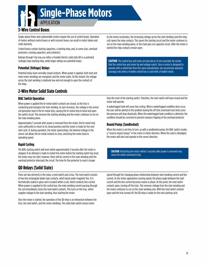
BIAC Switch OperationWhen power is applied the bi-metal switch contacts are closed, so the triac is conducting and energizes the start winding. As rpm increases, the voltage in the sensor coil generates heat in the bi-metal strip, causing the bi-metal strip to bend and open the switch circuit. This removes the starting winding and the motor continues to run on the main winding alone.
Approximately 5 seconds after power is removed from the motor, the bi-metal strip cools sufficiently to return to its closed position and the motor is ready for the next start cycle. If, during operation, the motor speed drops, the lowered voltage in the sensor coil allows the bi-metal contacts to close, and bring the motor back to operating speed.
Rapid CyclingThe BIAC starting switch will reset within approximately 5 seconds after the motor is stopped. If an attempt is made to restart the motor before the starting switch has reset, the motor may not start; however, there will be current in the main winding until the overload protector interrupts the circuit. The time for the protector to reset is longer
2-Wire Motor Solid State Controlsthan the reset of the starting switch. Therefore, the start switch will have closed and the motor will operate.
A waterlogged tank will cause fast cycling. When a waterlogged condition does occur, the user will be alerted to the problem during the off time (overload reset time) since the pressure will drop drastically. When the waterlogged tank condition is detected, the condition should be corrected to prevent nuisance tripping of the overload protector.
Bound Pump (Sandlocked)When the motor is not free to turn, as with a sandlocked pump, the BIAC switch creates a “reverse impact torque” in the motor in either direction. When the sand is dislodged, the motor will start and operate in the correct direction.
There are two elements in the relay: a reed switch and a triac. The reed switch consists of two tiny rectangular blade-type contacts, which bend under magnetic flux. It is hermetically sealed in glass and is located within a coil, which conducts line current. When power is supplied to the control box, the main winding current passing through the coil immediately closes the reed switch contacts. This turns on the triac, which supplies voltage to the start winding, thus starting the motor.
Once the motor is started, the operation of the QD relay is an interaction between the triac, the reed switch, and the motor windings. The solid state switch senses motor
speed through the changing phase relationship between start winding current and line current. As the motor approaches running speed, the phase angle between the start current and the line current becomes nearly in phase. At this point, the reed switch contacts open, turning off the triac. This removes voltage from the start winding and the motor continues to run on the main winding only. With the reed switch contacts open and the triac turned off, the QD relay is ready for the next starting cycle.
Single-phase three-wire submersible motors require the use of control boxes. Operation of motors without control boxes or with incorrect boxes can result in motor failure and voids warranty.
Control boxes contain starting capacitors, a starting relay, and, in some sizes, overload protectors, running capacitors, and contactors.
Ratings through 1 hp may use either a Franklin Electric solid state QD or a potential (voltage) type starting relay, while larger ratings use potential relays.
Potential (Voltage) Relays Potential relays have normally closed contacts. When power is applied, both start and main motor windings are energized, and the motor starts. At this instant, the voltage across the start winding is relatively low and not enough to open the contacts of the relay.
3-Wire Control Boxes
CAUTION: The control box and motor are two pieces of one assembly. Be certain that the control box and motor hp and voltage match. Since a motor is designed to operate with a control box from the same manufacturer, we can promise warranty coverage only when a Franklin control box is used with a Franklin motor.
CAUTION: Restarting the motor within 5 seconds after power is removed may cause the motor overload to trip.
QD Relays (Solid State)
10
As the motor accelerates, the increasing voltage across the start winding (and the relay coil) opens the relay contacts. This opens the starting circuit and the motor continues to run on the main winding alone, or the main plus run capacitor circuit. After the motor is started the relay contacts remain open.
Single-Phase MotorsAPPLICATION
75 °C
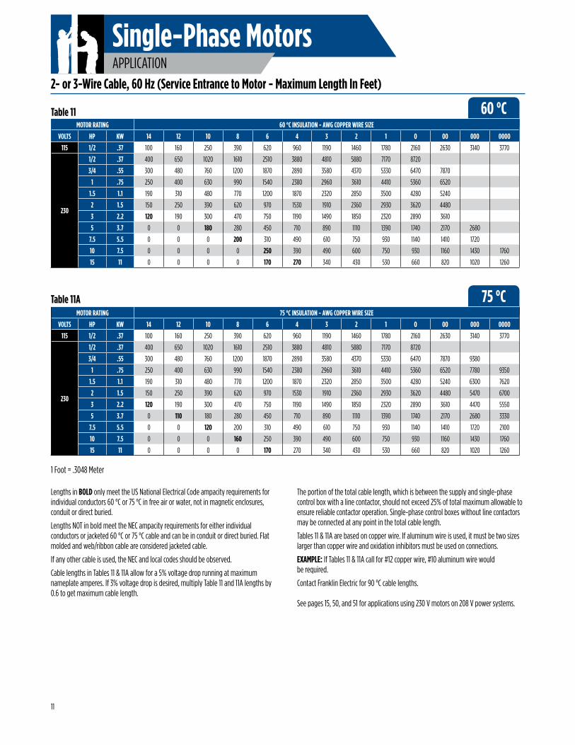
2- or 3-Wire Cable, 60 Hz (Service Entrance to Motor - Maximum Length In Feet)
Lengths in BOLD only meet the US National Electrical Code ampacity requirements for individual conductors 60 °C or 75 °C in free air or water, not in magnetic enclosures, conduit or direct buried.
Lengths NOT in bold meet the NEC ampacity requirements for either individual conductors or jacketed 60 °C or 75 °C cable and can be in conduit or direct buried. Flat molded and web/ribbon cable are considered jacketed cable.
If any other cable is used, the NEC and local codes should be observed.
Cable lengths in Tables 11 & 11A allow for a 5% voltage drop running at maximum nameplate amperes. If 3% voltage drop is desired, multiply Table 11 and 11A lengths by 0.6 to get maximum cable length.
The portion of the total cable length, which is between the supply and single-phase control box with a line contactor, should not exceed 25% of total maximum allowable to ensure reliable contactor operation. Single-phase control boxes without line contactors may be connected at any point in the total cable length.
Tables 11 & 11A are based on copper wire. If aluminum wire is used, it must be two sizes larger than copper wire and oxidation inhibitors must be used on connections.
EXAMPLE: If Tables 11 & 11A call for #12 copper wire, #10 aluminum wire would be required.
Contact Franklin Electric for 90 °C cable lengths. See pages 15, 50, and 51 for applications using 230 V motors on 208 V power systems.
MOTOR RATING 60 °C INSULATION - AWG COPPER WIRE SIZE
VOLTS HP KW 14 12 10 8 6 4 3 2 1 0 00 000 0000
115 1/2 .37 100 160 250 390 620 960 1190 1460 1780 2160 2630 3140 3770
230
1/2 .37 400 650 1020 1610 2510 3880 4810 5880 7170 8720
3/4 .55 300 480 760 1200 1870 2890 3580 4370 5330 6470 7870
1 .75 250 400 630 990 1540 2380 2960 3610 4410 5360 6520
1.5 1.1 190 310 480 770 1200 1870 2320 2850 3500 4280 5240
2 1.5 150 250 390 620 970 1530 1910 2360 2930 3620 4480
3 2.2 120 190 300 470 750 1190 1490 1850 2320 2890 3610
5 3.7 0 0 180 280 450 710 890 1110 1390 1740 2170 2680
7.5 5.5 0 0 0 200 310 490 610 750 930 1140 1410 1720
10 7.5 0 0 0 0 250 390 490 600 750 930 1160 1430 1760
15 11 0 0 0 0 170 270 340 430 530 660 820 1020 1260
Table 11
MOTOR RATING 75 °C INSULATION - AWG COPPER WIRE SIZE
VOLTS HP KW 14 12 10 8 6 4 3 2 1 0 00 000 0000
115 1/2 .37 100 160 250 390 620 960 1190 1460 1780 2160 2630 3140 3770
230
1/2 .37 400 650 1020 1610 2510 3880 4810 5880 7170 8720
3/4 .55 300 480 760 1200 1870 2890 3580 4370 5330 6470 7870 9380
1 .75 250 400 630 990 1540 2380 2960 3610 4410 5360 6520 7780 9350
1.5 1.1 190 310 480 770 1200 1870 2320 2850 3500 4280 5240 6300 7620
2 1.5 150 250 390 620 970 1530 1910 2360 2930 3620 4480 5470 6700
3 2.2 120 190 300 470 750 1190 1490 1850 2320 2890 3610 4470 5550
5 3.7 0 110 180 280 450 710 890 1110 1390 1740 2170 2680 3330
7.5 5.5 0 0 120 200 310 490 610 750 930 1140 1410 1720 2100
10 7.5 0 0 0 160 250 390 490 600 750 930 1160 1430 1760
15 11 0 0 0 0 170 270 340 430 530 660 820 1020 1260
Table 11A
1 Foot = .3048 Meter
60 °C
11
Single-Phase MotorsAPPLICATION
3 hp, 230 VSingle-Phase Motor
310 ft
#6 A
WG
(41.3%
of al
lowab
le ca
ble)
160 ft #10 AWG(53.3% of allowable cable)
Pump Controls
Cable
Service Entrance(Main Fuse Box From Meter)
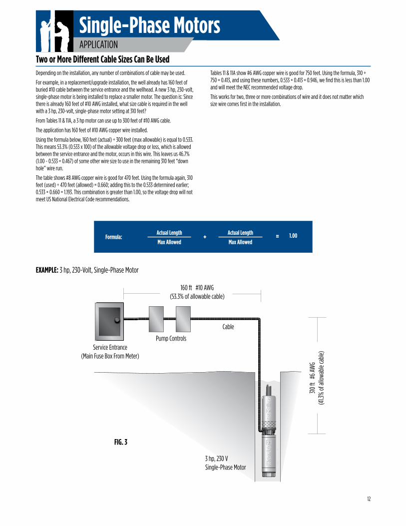
Depending on the installation, any number of combinations of cable may be used.
For example, in a replacement/upgrade installation, the well already has 160 feet of buried #10 cable between the service entrance and the wellhead. A new 3 hp, 230-volt, single-phase motor is being installed to replace a smaller motor. The question is: Since there is already 160 feet of #10 AWG installed, what size cable is required in the well with a 3 hp, 230-volt, single-phase motor setting at 310 feet?
From Tables 11 & 11A, a 3 hp motor can use up to 300 feet of #10 AWG cable.
The application has 160 feet of #10 AWG copper wire installed.
Using the formula below, 160 feet (actual) ÷ 300 feet (max allowable) is equal to 0.533. This means 53.3% (0.533 x 100) of the allowable voltage drop or loss, which is allowed between the service entrance and the motor, occurs in this wire. This leaves us 46.7% (1.00 - 0.533 = 0.467) of some other wire size to use in the remaining 310 feet “down hole” wire run.
The table shows #8 AWG copper wire is good for 470 feet. Using the formula again, 310 feet (used) ÷ 470 feet (allowed) = 0.660; adding this to the 0.533 determined earlier; 0.533 + 0.660 = 1.193. This combination is greater than 1.00, so the voltage drop will not meet US National Electrical Code recommendations.
Tables 11 & 11A show #6 AWG copper wire is good for 750 feet. Using the formula, 310 ÷ 750 = 0.413, and using these numbers, 0.533 + 0.413 = 0.946, we find this is less than 1.00 and will meet the NEC recommended voltage drop.
This works for two, three or more combinations of wire and it does not matter which size wire comes first in the installation.
EXAMPLE: 3 hp, 230-Volt, Single-Phase Motor
Two or More Different Cable Sizes Can Be Used
FIG. 3
Formula: + = 1.00Actual Length
Max Allowed
Actual Length
Max Allowed
12
Single-Phase MotorsAPPLICATION
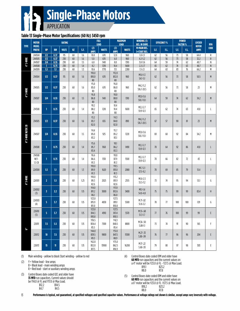
(1) Main winding - yellow to black Start winding - yellow to red
(2) Y = Yellow lead - line amps B = Black lead - main winding amps R = Red lead - start or auxiliary winding amps
(3) Control Boxes date coded 02C and older have 35 MFD run capacitors. Current values should be Y14.0 @ FL and Y17.0 @ Max Load. B12.2 B14.5 R4.7 R4.5
(4) Control Boxes date coded 01M and older have 60 MFD run capacitors and the current values on a 4" motor will be Y23.0 @ FL - Y27.5 @ Max Load. B19.1 B23.2 R8.0 R7.8
(5) Control Boxes date coded 01M and older have 60 MFD run capacitors and the current values on a 6" motor will be Y23.0 @ FL -Y27.5 @ Max Load. B18.2 B23.2 R8.0 R7.8
Performance is typical, not guaranteed, at specified voltages and specified capacitor values. Performance at voltage ratings not shown is similar, except amps vary inversely with voltage.
TYPEMOTORMODELPREFIX
RATINGFULL
LOADMAXIMUM
LOADWINDING (1)RES. IN OHMS
EFFICIENCY %POWER
FACTOR %LOCKEDROTORAMPS
KVACODE
HP KW VOLTS HZ S.F.(2)
AMPSWATTS
(2)AMPS
WATTSM=MAIN RES.S=START RES.
S.F. F.L. S.F. F.L.
4" 2-
WIR
E
244504 1/2 0.37 115 60 1.6 10.0 670 12.0 960 1.0-1.3 62 56 73 58 64.4 R244505 1/2 0.37 230 60 1.6 5.0 670 6.0 960 4.2-5.2 62 56 73 58 32.2 R244507 3/4 0.55 230 60 1.5 6.8 940 8.0 1310 3.0-3.6 64 59 74 62 40.7 N244508 1 0.75 230 60 1.4 8.2 1210 10.4 1600 2.2-2.7 65 62 74 63 48.7 N244309 1.5 1.1 230 60 1.3 10.6 1770 13.1 2280 1.5-2.1 64 63 83 76 66.2 M
Table 13 Single-Phase Motor Specifications (60 Hz) 3450 rpm
13
4" 3-
WIR
E
214504 1/2 0.37 115 60 1.6Y10.0B10.0
R0670
Y12.0B12.0
R0960
M1.0-1.3S4.1-5.1
62 56 73 58 50.5 M
214505 1/2 0.37 230 60 1.6Y5.0B5.0R0
670Y6.0B6.0R0
960M4.2-5.2
S16.7-20.562 56 73 58 23 M
214507 3/4 0.55 230 60 1.5Y6.8B6.8R0
940Y8.0B8.0R0
1310M3.0-3.6S10.7-13.1
64 59 74 62 34.2 M
214508 1 0.75 230 60 1.4Y8.2B8.2R0
121010.410.4R0
1600M2.2-2.7S9.9-12.1
65 62 74 63 41.8 L
4" 3-
WIR
E W/C
RC CB
214505 1/2 0.37 230 60 1.6Y3.2B3.7R2.0
655Y4.3B4.0R2.0
890M4.2-5.2
S16.7-20.567 57 90 81 23 M
214507 3/4 0.55 230 60 1.5Y4.4B5.0R3.2
925Y5.7B5.2R3.1
1220M3.0-3.6S10.7-13.1
69 60 92 84 34.2 M
214508 1 0.75 230 60 1.4Y5.6B5.7R3.4
1160Y8.1B6.2R3.3
1490M2.2-2.7S9.9-12.1
70 64 92 86 41.8 L
4" 3-
WIR
E
214508W/1- 1.5 CB
1 0.75 230 60 1.4Y6.6B6.6R1.3
1130Y8.0B7.9R1.3
1500M2.2-2.7S9.9-12.1
70 66 82 72 43 L
224300 1.5 1.1 230 60 1.3Y10.0B9.9R1.3
1620Y11.5B11.0R1.3
2080M1.7-2.1S7.5-9.2
70 69 85 79 51.4 J
224301 2 1.5 230 60 1.25Y10.0B9.3R2.6
2025Y13.2B11.9R2.6
2555M1.8-2.3S5.5-7.2
73 74 95 94 53.1 G
224302(3)
3 2.2 230 60 1.15Y14.0B11.2R6.1
3000Y17.0B12.6R6.0
3400M1.1-1.4
S4.0-4.875 75 99 99 83.4 H
224303(4)
5 3.7 230 60 1.15Y23.0B15.9R11.0
4830Y27.5B19.1R10.8
5500M.71-.82S1.8-2.2
78 77 100 100 129 G
6"
226110(5)
5 3.7 230 60 1.15Y23.0B14.3R10.8
4910Y27.5B17.4R10.5
5570M.55-.68S1.3-1.7
77 76 100 99 99 E
226111 7.5 5.5 230 60 1.15Y36.5B34.4R5.5
7300Y42.1B40.5R5.4
8800M.36-.50S.88-1.1
73 74 91 90 165 F
226112 10 7.5 230 60 1.15Y44.0B39.5R9.3
9800Y51.0B47.5R8.9
11300M.27-.33S.80-.99
76 77 96 96 204 E
226113 15 11 230 60 1.15Y62.0B52.0R17.5
13900Y75.0B62.5R16.9
16200M.17-.22S.68-.93
79 80 97 98 303 E
Single-Phase MotorsAPPLICATION
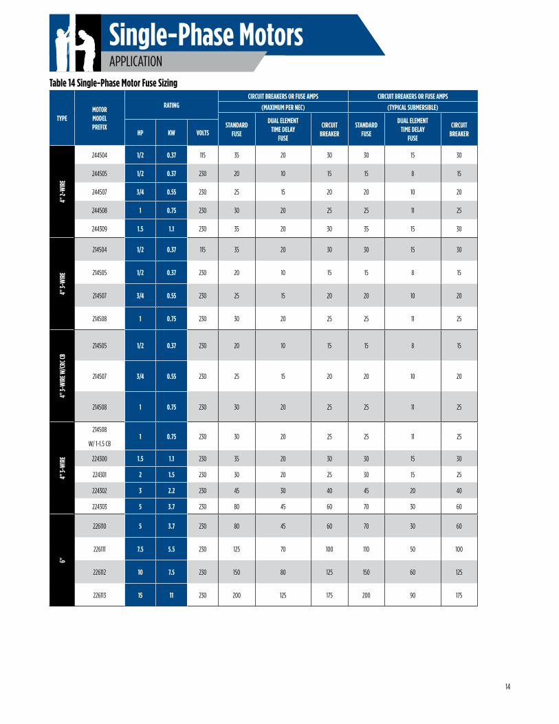
Table 14 Single-Phase Motor Fuse Sizing
TYPEMOTORMODELPREFIX
RATINGCIRCUIT BREAKERS OR FUSE AMPS CIRCUIT BREAKERS OR FUSE AMPS
(MAXIMUM PER NEC) (TYPICAL SUBMERSIBLE)
STANDARDFUSE
DUAL ELEMENTTIME DELAY
FUSE
CIRCUITBREAKER
STANDARDFUSE
DUAL ELEMENTTIME DELAY
FUSE
CIRCUITBREAKERHP KW VOLTS
4" 2-
WIR
E
244504 1/2 0.37 115 35 20 30 30 15 30
244505 1/2 0.37 230 20 10 15 15 8 15
244507 3/4 0.55 230 25 15 20 20 10 20
244508 1 0.75 230 30 20 25 25 11 25
244309 1.5 1.1 230 35 20 30 35 15 30
4" 3-
WIR
E
214504 1/2 0.37 115 35 20 30 30 15 30
214505 1/2 0.37 230 20 10 15 15 8 15
214507 3/4 0.55 230 25 15 20 20 10 20
214508 1 0.75 230 30 20 25 25 11 25
4" 3-
WIR
E W/C
RC CB
214505 1/2 0.37 230 20 10 15 15 8 15
214507 3/4 0.55 230 25 15 20 20 10 20
214508 1 0.75 230 30 20 25 25 11 25
4" 3-
WIR
E
2145081 0.75 230 30 20 25 25 11 25
W/ 1-1.5 CB
224300 1.5 1.1 230 35 20 30 30 15 30
224301 2 1.5 230 30 20 25 30 15 25
224302 3 2.2 230 45 30 40 45 20 40
224303 5 3.7 230 80 45 60 70 30 60
6"
226110 5 3.7 230 80 45 60 70 30 60
226111 7.5 5.5 230 125 70 100 110 50 100
226112 10 7.5 230 150 80 125 150 60 125
226113 15 11 230 200 125 175 200 90 175
14
Single-Phase MotorsAPPLICATION
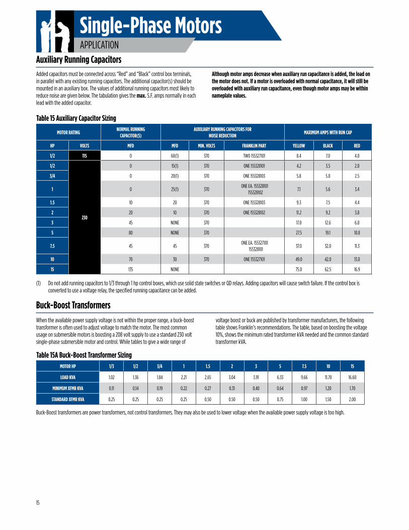
Buck-Boost transformers are power transformers, not control transformers. They may also be used to lower voltage when the available power supply voltage is too high.
When the available power supply voltage is not within the proper range, a buck-boost transformer is often used to adjust voltage to match the motor. The most common usage on submersible motors is boosting a 208 volt supply to use a standard 230 volt single-phase submersible motor and control. While tables to give a wide range of
voltage boost or buck are published by transformer manufacturers, the following table shows Franklin’s recommendations. The table, based on boosting the voltage 10%, shows the minimum rated transformer kVA needed and the common standard transformer kVA.
(1) Do not add running capacitors to 1/3 through 1 hp control boxes, which use solid state switches or QD relays. Adding capacitors will cause switch failure. If the control box is converted to use a voltage relay, the specified running capacitance can be added.
Table 15A Buck-Boost Transformer Sizing
Table 15 Auxiliary Capacitor Sizing
MOTOR RATINGNORMAL RUNNING
CAPACITOR(S)AUXILIARY RUNNING CAPACITORS FOR
NOISE REDUCTIONMAXIMUM AMPS WITH RUN CAP
HP VOLTS MFD MFD MIN. VOLTS FRANKLIN PART YELLOW BLACK RED
1/2 115 0 60(1) 370 TWO 155327101 8.4 7.0 4.0
1/2
230
0 15(1) 370 ONE 155328101 4.2 3.5 2.0
3/4 0 20(1) 370 ONE 155328103 5.8 5.0 2.5
1 0 25(1) 370 ONE EA. 155328101
1553281027.1 5.6 3.4
1.5 10 20 370 ONE 155328103 9.3 7.5 4.4
2 20 10 370 ONE 155328102 11.2 9.2 3.8
3 45 NONE 370 17.0 12.6 6.0
5 80 NONE 370 27.5 19.1 10.8
7.5 45 45 370 ONE EA. 155327101
15532810137.0 32.0 11.3
10 70 30 370 ONE 155327101 49.0 42.0 13.0
15 135 NONE 75.0 62.5 16.9
MOTOR HP 1/3 1/2 3/4 1 1.5 2 3 5 7.5 10 15
LOAD KVA 1.02 1.36 1.84 2.21 2.65 3.04 3.91 6.33 9.66 11.70 16.60
MINIMUM XFMR KVA 0.11 0.14 0.19 0.22 0.27 0.31 0.40 0.64 0.97 1.20 1.70
STANDARD XFMR KVA 0.25 0.25 0.25 0.25 0.50 0.50 0.50 0.75 1.00 1.50 2.00
Auxiliary Running Capacitors
Buck-Boost Transformers
Added capacitors must be connected across “Red” and “Black” control box terminals, in parallel with any existing running capacitors. The additional capacitor(s) should be mounted in an auxiliary box. The values of additional running capacitors most likely to reduce noise are given below. The tabulation gives the max. S.F. amps normally in each lead with the added capacitor.
Although motor amps decrease when auxiliary run capacitance is added, the load on the motor does not. If a motor is overloaded with normal capacitance, it will still be overloaded with auxiliary run capacitance, even though motor amps may be within nameplate values.
15
Three-Phase MotorsAPPLICATION
Continued on next page
60 °CMOTOR RATING 60 °C INSULATION - AWG COPPER WIRE SIZE MCM COPPER WIRE SIZE
VOLTS HP KW 14 12 10 8 6 4 3 2 1 0 00 000 0000 250 300 350 400 500
200 V60 Hz
Three-Phase
3 - Lead
1/2 0.37 710 1140 1800 2840 44203/4 0.55 510 810 1280 2030 3160
1 0.75 430 690 1080 1710 2670 4140 51401.5 1.1 310 500 790 1260 1960 3050 37802 1.5 240 390 610 970 1520 2360 2940 3610 4430 54203 2.2 180 290 470 740 1160 1810 2250 2760 3390 41305 3.7 110 170 280 440 690 1080 1350 1660 2040 2490 3050 3670 4440 5030
7.5 5.5 0 0 200 310 490 770 960 1180 1450 1770 2170 2600 3150 356010 7.5 0 0 0 230 370 570 720 880 1090 1330 1640 1970 2390 2720 3100 3480 3800 442015 11 0 0 0 160 250 390 490 600 740 910 1110 1340 1630 1850 2100 2350 2570 298020 15 0 0 0 0 190 300 380 460 570 700 860 1050 1270 1440 1650 1850 2020 236025 18.5 0 0 0 0 0 240 300 370 460 570 700 840 1030 1170 1330 1500 1640 190030 22 0 0 0 0 0 0 250 310 380 470 580 700 850 970 1110 1250 1360 1590
230 V60 Hz
Three-Phase
3 - Lead
1/2 0.37 930 1490 2350 3700 5760 89103/4 0.55 670 1080 1700 2580 4190 6490 8060 9860
1 0.75 560 910 1430 2260 3520 5460 6780 82901.5 1.1 420 670 1060 1670 2610 4050 5030 6160 7530 91702 1.5 320 510 810 1280 2010 3130 3890 4770 5860 7170 87803 2.2 240 390 620 990 1540 2400 2980 3660 4480 5470 6690 8020 96805 3.7 140 230 370 590 920 1430 1790 2190 2690 3290 4030 4850 5870 6650 7560 8460 9220
7.5 5.5 0 160 260 420 650 1020 1270 1560 1920 2340 2870 3440 4160 4710 5340 5970 6500 751010 7.5 0 0 190 310 490 760 950 1170 1440 1760 2160 2610 3160 3590 4100 4600 5020 584015 11 0 0 0 210 330 520 650 800 980 1200 1470 1780 2150 2440 2780 3110 3400 394020 15 0 0 0 0 250 400 500 610 760 930 1140 1380 1680 1910 2180 2450 2680 312025 18.5 0 0 0 0 0 320 400 500 610 750 920 1120 1360 1540 1760 1980 2160 252030 22 0 0 0 0 0 260 330 410 510 620 760 930 1130 1280 1470 1650 1800 2110
380 V60 Hz
Three-Phase
3 - Lead
1/2 0.37 2690 4290 67303/4 0.55 2000 3190 5010 7860
1 0.75 1620 2580 4060 6390 99801.5 1.1 1230 1970 3100 4890 76302 1.5 870 1390 2180 3450 5400 83803 2.2 680 1090 1710 2690 4200 6500 8020 98305 3.7 400 640 1010 1590 2490 3870 4780 5870 7230 8830
7.5 5.5 270 440 690 1090 1710 2640 3260 4000 4930 6010 7290 878010 7.5 200 320 510 800 1250 1930 2380 2910 3570 4330 5230 6260 7390 8280 934015 11 0 0 370 590 920 1430 1770 2170 2690 3290 4000 4840 5770 6520 7430 8250 899020 15 0 0 0 440 700 1090 1350 1670 2060 2530 3090 3760 4500 5110 5840 6510 7120 819025 18.5 0 0 0 360 570 880 1100 1350 1670 2050 2510 3040 3640 4130 4720 5250 5740 659030 22 0 0 0 0 470 730 910 1120 1380 1700 2080 2520 3020 3430 3920 4360 4770 549040 30 0 0 0 0 0 530 660 820 1010 1240 1520 1840 2200 2500 2850 3170 3470 399050 37 0 0 0 0 0 0 540 660 820 1000 1220 1480 1770 2010 2290 2550 2780 319060 45 0 0 0 0 0 0 0 560 690 850 1030 1250 1500 1700 1940 2150 2350 270075 55 0 0 0 0 0 0 0 0 570 700 860 1050 1270 1440 1660 1850 2030 2350
100 75 0 0 0 0 0 0 0 0 0 510 630 760 910 1030 1180 1310 1430 1650125 93 0 0 0 0 0 0 0 0 0 0 0 620 740 840 950 1060 1160 1330150 110 0 0 0 0 0 0 0 0 0 0 0 0 620 700 790 880 960 1090175 130 0 0 0 0 0 0 0 0 0 0 0 0 0 650 750 840 920 1070200 150 0 0 0 0 0 0 0 0 0 0 0 0 0 0 630 700 760 880
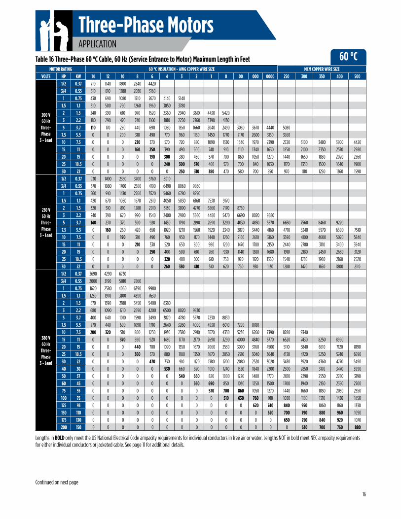
Lengths in BOLD only meet the US National Electrical Code ampacity requirements for individual conductors in free air or water. Lengths NOT in bold meet NEC ampacity requirements for either individual conductors or jacketed cable. See page 11 for additional details.
Table 16 Three-Phase 60 °C Cable, 60 Hz (Service Entrance to Motor) Maximum Length in Feet
16
Three-Phase MotorsAPPLICATION
60 °CMOTOR RATING 60 °C INSULATION - AWG COPPER WIRE SIZE MCM COPPER WIRE SIZE
VOLTS HP KW 14 12 10 8 6 4 3 2 1 0 00 000 0000 250 300 350 400 500
460 V60 Hz
Three-Phase
3 - Lead
1/2 0.37 3770 6020 9460
3/4 0.55 2730 4350 6850
1 0.75 2300 3670 5770 9070
1.5 1.1 1700 2710 4270 6730
2 1.5 1300 2070 3270 5150 8050
3 2.2 1000 1600 2520 3970 6200
5 3.7 590 950 1500 2360 3700 5750
7.5 5.5 420 680 1070 1690 2640 4100 5100 6260 7680
10 7.5 310 500 790 1250 1960 3050 3800 4680 5750 7050
15 11 0 340 540 850 1340 2090 2600 3200 3930 4810 5900 7110
20 15 0 0 410 650 1030 1610 2000 2470 3040 3730 4580 5530
25 18.5 0 0 0 530 830 1300 1620 1990 2450 3010 3700 4470 5430
30 22 0 0 0 430 680 1070 1330 1640 2030 2490 3060 3700 4500 5130 5860
40 30 0 0 0 0 500 790 980 1210 1490 1830 2250 2710 3290 3730 4250
50 37 0 0 0 0 0 640 800 980 1210 1480 1810 2190 2650 3010 3420 3830 4180 4850
60 45 0 0 0 0 0 540 670 830 1020 1250 1540 1850 2240 2540 2890 3240 3540 4100
75 55 0 0 0 0 0 0 0 680 840 1030 1260 1520 1850 2100 2400 2700 2950 3440
100 75 0 0 0 0 0 0 0 0 620 760 940 1130 1380 1560 1790 2010 2190 2550
125 93 0 0 0 0 0 0 0 0 0 0 740 890 1000 1220 1390 1560 1700 1960
150 110 0 0 0 0 0 0 0 0 0 0 0 760 920 1050 1190 1340 1460 1690
175 130 0 0 0 0 0 0 0 0 0 0 0 0 810 930 1060 1190 1300 1510
200 150 0 0 0 0 0 0 0 0 0 0 0 0 0 810 920 1030 1130 1310
575 V60 Hz
Three-Phase
3 - Lead
1/2 0.37 5900 9410
3/4 0.55 4270 6810
1 0.75 3630 5800 9120
1.5 1.1 2620 4180 6580
2 1.5 2030 3250 5110 8060
3 2.2 1580 2530 3980 6270
5 3.7 920 1480 2330 3680 5750
7.5 5.5 660 1060 1680 2650 4150
10 7.5 490 780 1240 1950 3060 4770 5940
15 11 330 530 850 1340 2090 3260 4060
20 15 0 410 650 1030 1610 2520 3140 3860 4760 5830
25 18.5 0 0 520 830 1300 2030 2530 3110 3840 4710
30 22 0 0 430 680 1070 1670 2080 2560 3160 3880 4770 5780 7030 8000
40 30 0 0 0 500 790 1240 1540 1900 2330 2860 3510 4230 5140 5830
50 37 0 0 0 0 640 1000 1250 1540 1890 2310 2840 3420 4140 4700 5340 5990 6530 7580
60 45 0 0 0 0 0 850 1060 1300 1600 1960 2400 2890 3500 3970 4520 5070 5530 6410
75 55 0 0 0 0 0 690 860 1060 1310 1600 1970 2380 2890 3290 3750 5220 4610 5370
100 75 0 0 0 0 0 0 0 790 970 1190 1460 1770 2150 2440 2790 3140 3430 3990
125 93 0 0 0 0 0 0 0 0 770 950 1160 1400 1690 1920 2180 2440 2650 3070
150 110 0 0 0 0 0 0 0 0 0 800 990 1190 1440 1630 1860 2080 2270 2640
175 130 0 0 0 0 0 0 0 0 0 0 870 1050 1270 1450 1650 1860 2030 2360
200 150 0 0 0 0 0 0 0 0 0 0 0 920 1110 1260 1440 1620 1760 2050
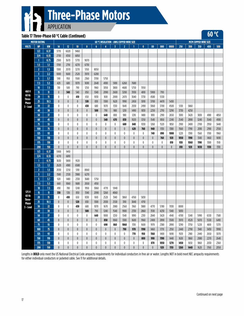
Lengths in BOLD only meet the US National Electrical Code ampacity requirements for individual conductors in free air or water. Lengths NOT in bold meet NEC ampacity requirements for either individual conductors or jacketed cable. See 11 for additional details.
Table 17 Three-Phase 60 °C Cable (Continued)
Continued on next page
17

Three-Phase MotorsAPPLICATION
60 °CMOTOR RATING 60 °C INSULATION - AWG COPPER WIRE SIZE MCM COPPER WIRE SIZE
VOLTS HP KW 14 12 10 8 6 4 3 2 1 0 00 000 0000 250 300 350 400 500
200 V60 Hz
Three-Phase
6 - LeadY-D
5 3.7 160 250 420 660 1030 1620 2020 2490 3060 3730 4570 5500 6660 75407.5 5.5 110 180 300 460 730 1150 1440 1770 2170 2650 3250 3900 4720 534010 7.5 80 130 210 340 550 850 1080 1320 1630 1990 2460 2950 3580 4080 4650 5220 5700 663015 11 0 0 140 240 370 580 730 900 1110 1360 1660 2010 2440 2770 3150 3520 3850 447020 15 0 0 0 170 280 450 570 690 850 1050 1290 1570 1900 2160 2470 2770 3030 354025 18.5 0 0 0 140 220 360 450 550 690 850 1050 1260 1540 1750 1990 2250 2460 285030 22 0 0 0 0 180 294 370 460 570 700 870 1050 1270 1450 1660 1870 2040 2380
230 V60 Hz
Three-Phase
6 - LeadY-D
5 3.7 210 340 550 880 1380 2140 2680 3280 4030 4930 6040 7270 8800 99707.5 5.5 150 240 390 630 970 1530 1900 2340 2880 3510 4300 5160 6240 7060 8010 8950 975010 7.5 110 180 280 460 730 1140 1420 1750 2160 2640 3240 3910 4740 5380 6150 6900 7530 876015 11 0 0 190 310 490 780 970 1200 1470 1800 2200 2670 3220 3660 4170 4660 5100 591020 15 0 0 140 230 370 600 750 910 1140 1390 1710 2070 2520 2860 3270 3670 4020 468025 18.5 0 0 0 190 300 480 600 750 910 1120 1380 1680 2040 2310 2640 2970 3240 378030 22 0 0 0 150 240 390 490 610 760 930 1140 1390 1690 1920 2200 2470 2700 3160
380 V60 Hz
Three-Phase
6 - LeadY-D
5 3.7 600 960 1510 2380 3730 5800 7170 88007.5 5.5 400 660 1030 1630 2560 3960 4890 6000 7390 901010 7.5 300 480 760 1200 1870 2890 3570 4360 5350 6490 7840 939015 11 210 340 550 880 1380 2140 2650 3250 4030 4930 6000 7260 8650 978020 15 160 260 410 660 1050 1630 2020 2500 3090 3790 4630 5640 6750 7660 4260 976025 18.5 0 210 330 540 850 1320 1650 2020 2500 3070 3760 4560 5460 6190 7080 7870 8610 988030 22 0 0 270 430 700 1090 1360 1680 2070 2550 3120 3780 4530 5140 5880 6540 7150 823040 30 0 0 0 320 510 790 990 1230 1510 1860 2280 2760 3300 3750 4270 4750 5200 598050 37 0 0 0 250 400 630 810 990 1230 1500 1830 2220 2650 3010 3430 3820 4170 478060 45 0 0 0 0 340 540 660 840 1030 1270 1540 1870 2250 2550 2910 3220 3520 405075 55 0 0 0 0 0 450 550 690 855 1050 1290 1570 1900 2160 2490 2770 3040 3520
100 75 0 0 0 0 0 0 420 520 640 760 940 1140 1360 1540 1770 1960 2140 2470125 93 0 0 0 0 0 0 0 400 490 600 730 930 1110 1260 1420 1590 1740 1990150 110 0 0 0 0 0 0 0 0 420 510 620 750 930 1050 1180 1320 1440 1630175 130 0 0 0 0 0 0 0 0 360 440 540 660 780 970 1120 1260 1380 1600200 150 0 0 0 0 0 0 0 0 0 0 480 580 690 790 940 1050 1140 1320
460 V60 Hz
Three-Phase
6 - LeadY-D
5 3.7 880 1420 2250 3540 5550 86207.5 5.5 630 1020 1600 2530 3960 6150 7650 939010 7.5 460 750 1180 1870 2940 4570 5700 7020 862015 11 310 510 810 1270 2010 3130 3900 4800 5890 7210 885020 15 230 380 610 970 1540 2410 3000 3700 4560 5590 6870 829025 18.5 190 310 490 790 1240 1950 2430 2980 3670 4510 5550 6700 814030 22 0 250 410 640 1020 1600 1990 2460 3040 3730 4590 5550 6750 7690 879040 30 0 0 300 480 750 1180 1470 1810 2230 2740 3370 4060 4930 5590 637050 37 0 0 0 370 590 960 1200 1470 1810 2220 2710 3280 3970 4510 5130 5740 6270 727060 45 0 0 0 320 500 810 1000 1240 1530 1870 2310 2770 3360 3810 4330 4860 5310 615075 55 0 0 0 0 420 660 810 1020 1260 1540 1890 2280 2770 3150 3600 4050 4420 5160
100 75 0 0 0 0 0 500 610 760 930 1140 1410 1690 2070 2340 2680 3010 3280 3820125 93 0 0 0 0 0 0 470 590 730 880 1110 1330 1500 1830 2080 2340 2550 2940150 110 0 0 0 0 0 0 0 510 630 770 950 1140 1380 1570 1790 2000 2180 2530175 130 0 0 0 0 0 0 0 0 550 680 830 1000 1220 1390 1580 1780 1950 2270200 150 0 0 0 0 0 0 0 0 0 590 730 880 1070 1210 1380 1550 1690 1970
575 V60 Hz
Three-Phase
6 - LeadY-D
5 3.7 1380 2220 3490 5520 86207.5 5.5 990 1590 2520 3970 622010 7.5 730 1170 1860 2920 4590 7150 891015 11 490 790 1270 2010 3130 4890 609020 15 370 610 970 1540 2410 3780 4710 5790 7140 874025 18.5 300 490 780 1240 1950 3040 3790 4660 5760 706030 22 240 400 645 1020 1600 2500 3120 3840 4740 5820 7150 867040 30 0 300 480 750 1180 1860 2310 2850 3490 4290 5260 6340 7710 874050 37 0 0 380 590 960 1500 1870 2310 2830 3460 4260 5130 6210 7050 8010 8980 979060 45 0 0 0 500 790 1270 1590 1950 2400 2940 3600 4330 5250 5950 6780 7600 8290 961075 55 0 0 0 420 660 1030 1290 1590 1960 2400 2950 3570 4330 4930 5620 6330 6910 8050
100 75 0 0 0 0 400 780 960 1180 1450 1780 2190 2650 3220 3660 4180 4710 5140 5980125 93 0 0 0 0 0 600 740 920 1150 1420 1740 2100 2530 2880 3270 3660 3970 4600150 110 0 0 0 0 0 0 650 800 990 1210 1480 1780 2160 2450 2790 3120 3410 3950175 130 0 0 0 0 0 0 0 700 860 1060 1300 1570 1910 2170 2480 2780 3040 3540200 150 0 0 0 0 0 0 0 0 760 930 1140 1370 1670 1890 2160 2420 2640 3070
Lengths in BOLD only meet the US National Electrical Code ampacity requirements for individual conductors in free air or water. Lengths NOT in bold meet NEC ampacity requirements for either individual conductors or jacketed cable. See page 11 for additional details.
Table 18 Three-Phase 60 °C Cable (Continued)
18
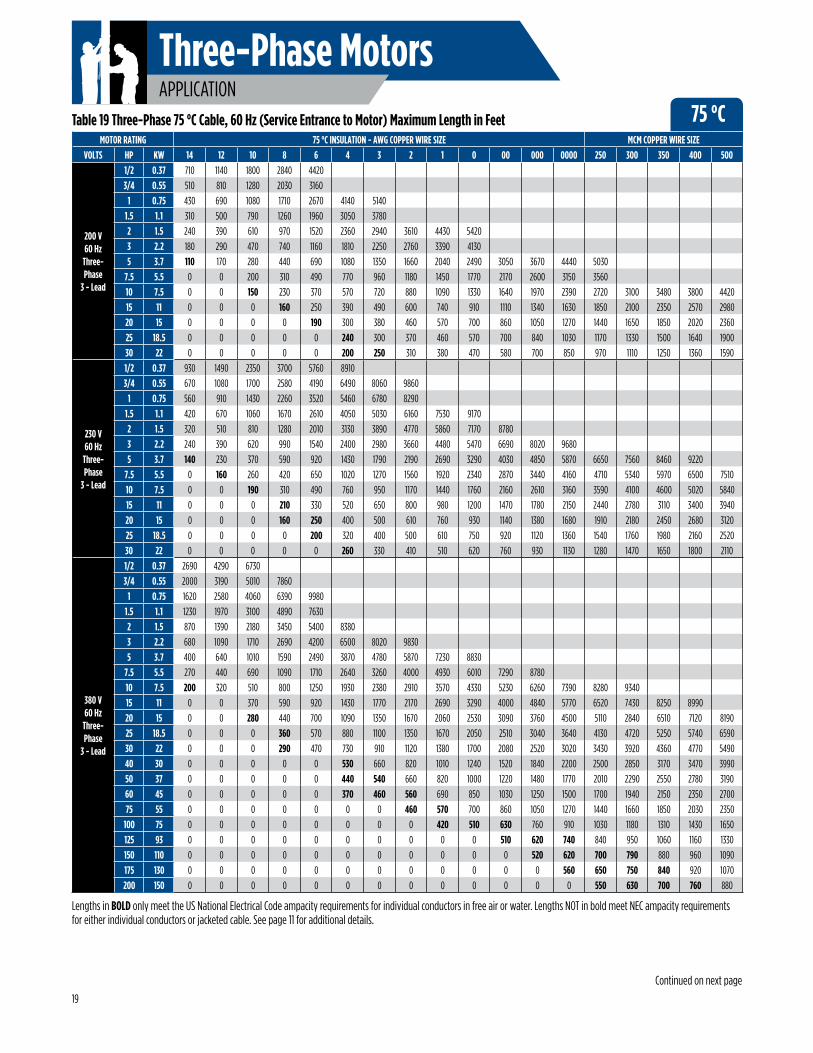
Three-Phase MotorsAPPLICATION
Continued on next page
75 °CMOTOR RATING 75 °C INSULATION - AWG COPPER WIRE SIZE MCM COPPER WIRE SIZE
VOLTS HP KW 14 12 10 8 6 4 3 2 1 0 00 000 0000 250 300 350 400 500
200 V60 Hz
Three-Phase
3 - Lead
1/2 0.37 710 1140 1800 2840 4420
3/4 0.55 510 810 1280 2030 3160
1 0.75 430 690 1080 1710 2670 4140 5140
1.5 1.1 310 500 790 1260 1960 3050 3780
2 1.5 240 390 610 970 1520 2360 2940 3610 4430 5420
3 2.2 180 290 470 740 1160 1810 2250 2760 3390 4130
5 3.7 110 170 280 440 690 1080 1350 1660 2040 2490 3050 3670 4440 5030
7.5 5.5 0 0 200 310 490 770 960 1180 1450 1770 2170 2600 3150 3560
10 7.5 0 0 150 230 370 570 720 880 1090 1330 1640 1970 2390 2720 3100 3480 3800 4420
15 11 0 0 0 160 250 390 490 600 740 910 1110 1340 1630 1850 2100 2350 2570 2980
20 15 0 0 0 0 190 300 380 460 570 700 860 1050 1270 1440 1650 1850 2020 2360
25 18.5 0 0 0 0 0 240 300 370 460 570 700 840 1030 1170 1330 1500 1640 1900
30 22 0 0 0 0 0 200 250 310 380 470 580 700 850 970 1110 1250 1360 1590
230 V60 Hz
Three-Phase
3 - Lead
1/2 0.37 930 1490 2350 3700 5760 8910
3/4 0.55 670 1080 1700 2580 4190 6490 8060 9860
1 0.75 560 910 1430 2260 3520 5460 6780 8290
1.5 1.1 420 670 1060 1670 2610 4050 5030 6160 7530 9170
2 1.5 320 510 810 1280 2010 3130 3890 4770 5860 7170 8780
3 2.2 240 390 620 990 1540 2400 2980 3660 4480 5470 6690 8020 9680
5 3.7 140 230 370 590 920 1430 1790 2190 2690 3290 4030 4850 5870 6650 7560 8460 9220
7.5 5.5 0 160 260 420 650 1020 1270 1560 1920 2340 2870 3440 4160 4710 5340 5970 6500 7510
10 7.5 0 0 190 310 490 760 950 1170 1440 1760 2160 2610 3160 3590 4100 4600 5020 5840
15 11 0 0 0 210 330 520 650 800 980 1200 1470 1780 2150 2440 2780 3110 3400 3940
20 15 0 0 0 160 250 400 500 610 760 930 1140 1380 1680 1910 2180 2450 2680 3120
25 18.5 0 0 0 0 200 320 400 500 610 750 920 1120 1360 1540 1760 1980 2160 2520
30 22 0 0 0 0 0 260 330 410 510 620 760 930 1130 1280 1470 1650 1800 2110
380 V60 Hz
Three-Phase
3 - Lead
1/2 0.37 2690 4290 6730
3/4 0.55 2000 3190 5010 7860
1 0.75 1620 2580 4060 6390 9980
1.5 1.1 1230 1970 3100 4890 7630
2 1.5 870 1390 2180 3450 5400 8380
3 2.2 680 1090 1710 2690 4200 6500 8020 9830
5 3.7 400 640 1010 1590 2490 3870 4780 5870 7230 8830
7.5 5.5 270 440 690 1090 1710 2640 3260 4000 4930 6010 7290 8780
10 7.5 200 320 510 800 1250 1930 2380 2910 3570 4330 5230 6260 7390 8280 9340
15 11 0 0 370 590 920 1430 1770 2170 2690 3290 4000 4840 5770 6520 7430 8250 8990
20 15 0 0 280 440 700 1090 1350 1670 2060 2530 3090 3760 4500 5110 2840 6510 7120 8190
25 18.5 0 0 0 360 570 880 1100 1350 1670 2050 2510 3040 3640 4130 4720 5250 5740 6590
30 22 0 0 0 290 470 730 910 1120 1380 1700 2080 2520 3020 3430 3920 4360 4770 5490
40 30 0 0 0 0 0 530 660 820 1010 1240 1520 1840 2200 2500 2850 3170 3470 3990
50 37 0 0 0 0 0 440 540 660 820 1000 1220 1480 1770 2010 2290 2550 2780 3190
60 45 0 0 0 0 0 370 460 560 690 850 1030 1250 1500 1700 1940 2150 2350 2700
75 55 0 0 0 0 0 0 0 460 570 700 860 1050 1270 1440 1660 1850 2030 2350
100 75 0 0 0 0 0 0 0 0 420 510 630 760 910 1030 1180 1310 1430 1650
125 93 0 0 0 0 0 0 0 0 0 0 510 620 740 840 950 1060 1160 1330
150 110 0 0 0 0 0 0 0 0 0 0 0 520 620 700 790 880 960 1090
175 130 0 0 0 0 0 0 0 0 0 0 0 0 560 650 750 840 920 1070
200 150 0 0 0 0 0 0 0 0 0 0 0 0 0 550 630 700 760 880
Lengths in BOLD only meet the US National Electrical Code ampacity requirements for individual conductors in free air or water. Lengths NOT in bold meet NEC ampacity requirements for either individual conductors or jacketed cable. See page 11 for additional details.
Table 19 Three-Phase 75 °C Cable, 60 Hz (Service Entrance to Motor) Maximum Length in Feet
19
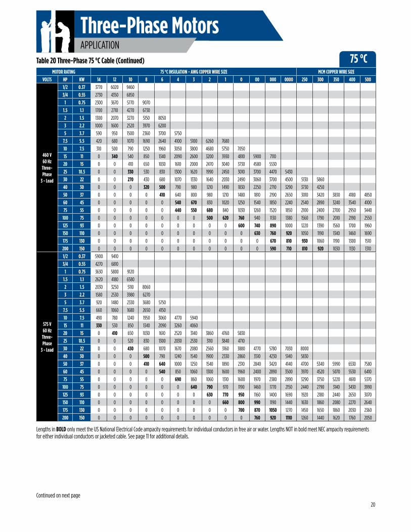
Three-Phase MotorsAPPLICATION
75 °CMOTOR RATING 75 °C INSULATION - AWG COPPER WIRE SIZE MCM COPPER WIRE SIZE
VOLTS HP KW 14 12 10 8 6 4 3 2 1 0 00 000 0000 250 300 350 400 500
460 V60 Hz
Three-Phase
3 - Lead
1/2 0.37 3770 6020 9460
3/4 0.55 2730 4350 6850
1 0.75 2300 3670 5770 9070
1.5 1.1 1700 2710 4270 6730
2 1.5 1300 2070 3270 5150 8050
3 2.2 1000 1600 2520 3970 6200
5 3.7 590 950 1500 2360 3700 5750
7.5 5.5 420 680 1070 1690 2640 4100 5100 6260 7680
10 7.5 310 500 790 1250 1960 3050 3800 4680 5750 7050
15 11 0 340 540 850 1340 2090 2600 3200 3930 4810 5900 7110
20 15 0 0 410 650 1030 1610 2000 2470 3040 3730 4580 5530
25 18.5 0 0 330 530 830 1300 1620 1990 2450 3010 3700 4470 5430
30 22 0 0 270 430 680 1070 1330 1640 2030 2490 3060 3700 4500 5130 5860
40 30 0 0 0 320 500 790 980 1210 1490 1830 2250 2710 3290 3730 4250
50 37 0 0 0 0 410 640 800 980 1210 1480 1810 2190 2650 3010 3420 3830 4180 4850
60 45 0 0 0 0 0 540 670 830 1020 1250 1540 1850 2240 2540 2890 3240 3540 4100
75 55 0 0 0 0 0 440 550 680 840 1030 1260 1520 1850 2100 2400 2700 2950 3440
100 75 0 0 0 0 0 0 0 500 620 760 940 1130 1380 1560 1790 2010 2190 2550
125 93 0 0 0 0 0 0 0 0 0 600 740 890 1000 1220 1390 1560 1700 1960
150 110 0 0 0 0 0 0 0 0 0 0 630 760 920 1050 1190 1340 1460 1690
175 130 0 0 0 0 0 0 0 0 0 0 0 670 810 930 1060 1190 1300 1510
200 150 0 0 0 0 0 0 0 0 0 0 0 590 710 810 920 1030 1130 1310
575 V60 Hz
Three-Phase
3 - Lead
1/2 0.37 5900 9410
3/4 0.55 4270 6810
1 0.75 3630 5800 9120
1.5 1.1 2620 4180 6580
2 1.5 2030 3250 5110 8060
3 2.2 1580 2530 3980 6270
5 3.7 920 1480 2330 3680 5750
7.5 5.5 660 1060 1680 2650 4150
10 7.5 490 780 1240 1950 3060 4770 5940
15 11 330 530 850 1340 2090 3260 4060
20 15 0 410 650 1030 1610 2520 3140 3860 4760 5830
25 18.5 0 0 520 830 1300 2030 2530 3110 3840 4710
30 22 0 0 430 680 1070 1670 2080 2560 3160 3880 4770 5780 7030 8000
40 30 0 0 0 500 790 1240 1540 1900 2330 2860 3510 4230 5140 5830
50 37 0 0 0 410 640 1000 1250 1540 1890 2310 2840 3420 4140 4700 5340 5990 6530 7580
60 45 0 0 0 0 540 850 1060 1300 1600 1960 2400 2890 3500 3970 4520 5070 5530 6410
75 55 0 0 0 0 0 690 860 1060 1310 1600 1970 2380 2890 3290 3750 5220 4610 5370
100 75 0 0 0 0 0 0 640 790 970 1190 1460 1770 2150 2440 2790 3140 3430 3990
125 93 0 0 0 0 0 0 0 630 770 950 1160 1400 1690 1920 2180 2440 2650 3070
150 110 0 0 0 0 0 0 0 0 660 800 990 1190 1440 1630 1860 2080 2270 2640
175 130 0 0 0 0 0 0 0 0 0 700 870 1050 1270 1450 1650 1860 2030 2360
200 150 0 0 0 0 0 0 0 0 0 0 760 920 1110 1260 1440 1620 1760 2050
Lengths in BOLD only meet the US National Electrical Code ampacity requirements for individual conductors in free air or water. Lengths NOT in bold meet NEC ampacity requirements for either individual conductors or jacketed cable. See page 11 for additional details.
Table 20 Three-Phase 75 °C Cable (Continued)
Continued on next page
20
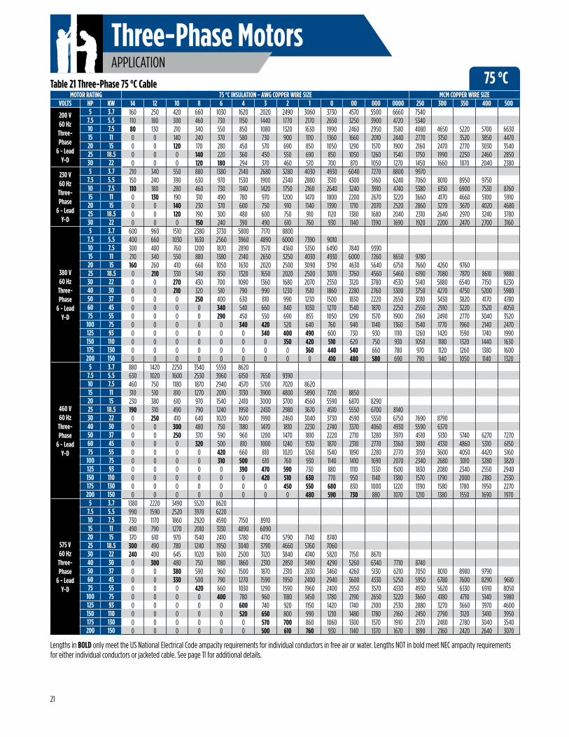
Three-Phase MotorsAPPLICATION
75 °CMOTOR RATING 75 °C INSULATION - AWG COPPER WIRE SIZE MCM COPPER WIRE SIZE
VOLTS HP KW 14 12 10 8 6 4 3 2 1 0 00 000 0000 250 300 350 400 500
200 V60 Hz
Three-Phase
6 - LeadY-D
5 3.7 160 250 420 660 1030 1620 2020 2490 3060 3730 4570 5500 6660 75407.5 5.5 110 180 300 460 730 1150 1440 1770 2170 2650 3250 3900 4720 534010 7.5 80 130 210 340 550 850 1080 1320 1630 1990 2460 2950 3580 4080 4650 5220 5700 663015 11 0 0 140 240 370 580 730 900 1110 1360 1660 2010 2440 2770 3150 3520 3850 447020 15 0 0 120 170 280 450 570 690 850 1050 1290 1570 1900 2160 2470 2770 3030 354025 18.5 0 0 0 140 220 360 450 550 690 850 1050 1260 1540 1750 1990 2250 2460 285030 22 0 0 0 120 180 294 370 460 570 700 870 1050 1270 1450 1660 1870 2040 2380
230 V60 Hz
Three-Phase
6 - LeadY-D
5 3.7 210 340 550 880 1380 2140 2680 3280 4030 4930 6040 7270 8800 99707.5 5.5 150 240 390 630 970 1530 1900 2340 2880 3510 4300 5160 6240 7060 8010 8950 975010 7.5 110 180 280 460 730 1140 1420 1750 2160 2640 3240 3910 4740 5380 6150 6900 7530 876015 11 0 130 190 310 490 780 970 1200 1470 1800 2200 2670 3220 3660 4170 4660 5100 591020 15 0 0 140 230 370 600 750 910 1140 1390 1710 2070 2520 2860 3270 3670 4020 468025 18.5 0 0 120 190 300 480 600 750 910 1120 1380 1680 2040 2310 2640 2970 3240 378030 22 0 0 0 150 240 390 490 610 760 930 1140 1390 1690 1920 2200 2470 2700 3160
380 V60 Hz
Three-Phase
6 - LeadY-D
5 3.7 600 960 1510 2380 3730 5800 7170 88007.5 5.5 400 660 1030 1630 2560 3960 4890 6000 7390 901010 7.5 300 480 760 1200 1870 2890 3570 4360 5350 6490 7840 939015 11 210 340 550 880 1380 2140 2650 3250 4030 4930 6000 7260 8650 978020 15 160 260 410 660 1050 1630 2020 2500 3090 3790 4630 5640 6750 7660 4260 976025 18.5 0 210 330 540 850 1320 1650 2020 2500 3070 3760 4560 5460 6190 7080 7870 8610 988030 22 0 0 270 430 700 1090 1360 1680 2070 2550 3120 3780 4530 5140 5880 6540 7150 823040 30 0 0 210 320 510 790 990 1230 1510 1860 2280 2760 3300 3750 4270 4750 5200 598050 37 0 0 0 250 400 630 810 990 1230 1500 1830 2220 2650 3010 3430 3820 4170 478060 45 0 0 0 0 340 540 660 840 1030 1270 1540 1870 2250 2550 2910 3220 3520 405075 55 0 0 0 0 290 450 550 690 855 1050 1290 1570 1900 2160 2490 2770 3040 3520
100 75 0 0 0 0 0 340 420 520 640 760 940 1140 1360 1540 1770 1960 2140 2470125 93 0 0 0 0 0 0 340 400 490 600 730 930 1110 1260 1420 1590 1740 1990150 110 0 0 0 0 0 0 0 350 420 510 620 750 930 1050 1180 1320 1440 1630175 130 0 0 0 0 0 0 0 0 360 440 540 660 780 970 1120 1260 1380 1600200 150 0 0 0 0 0 0 0 0 0 410 480 580 690 790 940 1050 1140 1320
460 V60 Hz
Three-Phase
6 - LeadY-D
5 3.7 880 1420 2250 3540 5550 86207.5 5.5 630 1020 1600 2530 3960 6150 7650 939010 7.5 460 750 1180 1870 2940 4570 5700 7020 862015 11 310 510 810 1270 2010 3130 3900 4800 5890 7210 885020 15 230 380 610 970 1540 2410 3000 3700 4560 5590 6870 829025 18.5 190 310 490 790 1240 1950 2430 2980 3670 4510 5550 6700 814030 22 0 250 410 640 1020 1600 1990 2460 3040 3730 4590 5550 6750 7690 879040 30 0 0 300 480 750 1180 1470 1810 2230 2740 3370 4060 4930 5590 637050 37 0 0 250 370 590 960 1200 1470 1810 2220 2710 3280 3970 4510 5130 5740 6270 727060 45 0 0 0 320 500 810 1000 1240 1530 1870 2310 2770 3360 3810 4330 4860 5310 615075 55 0 0 0 0 420 660 810 1020 1260 1540 1890 2280 2770 3150 3600 4050 4420 5160
100 75 0 0 0 0 310 500 610 760 930 1140 1410 1690 2070 2340 2680 3010 3280 3820125 93 0 0 0 0 0 390 470 590 730 880 1110 1330 1500 1830 2080 2340 2550 2940150 110 0 0 0 0 0 0 420 510 630 770 950 1140 1380 1570 1790 2000 2180 2530175 130 0 0 0 0 0 0 0 450 550 680 830 1000 1220 1390 1580 1780 1950 2270200 150 0 0 0 0 0 0 0 0 480 590 730 880 1070 1210 1380 1550 1690 1970
575 V60 Hz
Three-Phase
6 - LeadY-D
5 3.7 1380 2220 3490 5520 86207.5 5.5 990 1590 2520 3970 622010 7.5 730 1170 1860 2920 4590 7150 891015 11 490 790 1270 2010 3130 4890 609020 15 370 610 970 1540 2410 3780 4710 5790 7140 874025 18.5 300 490 780 1240 1950 3040 3790 4660 5760 706030 22 240 400 645 1020 1600 2500 3120 3840 4740 5820 7150 867040 30 0 300 480 750 1180 1860 2310 2850 3490 4290 5260 6340 7710 874050 37 0 0 380 590 960 1500 1870 2310 2830 3460 4260 5130 6210 7050 8010 8980 979060 45 0 0 330 500 790 1270 1590 1950 2400 2940 3600 4330 5250 5950 6780 7600 8290 961075 55 0 0 0 420 660 1030 1290 1590 1960 2400 2950 3570 4330 4930 5620 6330 6910 8050
100 75 0 0 0 0 400 780 960 1180 1450 1780 2190 2650 3220 3660 4180 4710 5140 5980125 93 0 0 0 0 0 600 740 920 1150 1420 1740 2100 2530 2880 3270 3660 3970 4600150 110 0 0 0 0 0 520 650 800 990 1210 1480 1780 2160 2450 2790 3120 3410 3950175 130 0 0 0 0 0 0 570 700 860 1060 1300 1570 1910 2170 2480 2780 3040 3540200 150 0 0 0 0 0 0 500 610 760 930 1140 1370 1670 1890 2160 2420 2640 3070
Lengths in BOLD only meet the US National Electrical Code ampacity requirements for individual conductors in free air or water. Lengths NOT in bold meet NEC ampacity requirements for either individual conductors or jacketed cable. See page 11 for additional details.
Table 21 Three-Phase 75 °C Cable
21
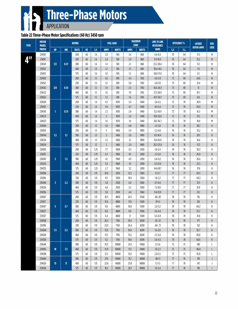
Three-Phase MotorsAPPLICATION
Table 22 Three-Phase Motor Specifications (60 Hz) 3450 rpm
22
TYPEMOTOR MODEL PREFIX
RATING FULL LOAD MAXIMUM
LOADLINE TO LINE RESISTANCE
OHMS
EFFICIENCY % LOCKED ROTOR AMPS
KVA CODE
HP KW VOLTS HZ S.F. AMPS WATTS AMPS WATTS S.F. F.L.
4"234501
1/2 0.37
200 60 1.6 2.8 585 3.4 860 6.6-8.4 70 64 17.5 N
234511 230 60 1.6 2.4 585 2.9 860 9.5-10.9 70 64 15.2 N
234541 380 60 1.6 1.4 585 2.1 860 23.2-28.6 70 64 9.2 N
234521 460 60 1.6 1.2 585 1.5 860 38.4-44.1 70 64 7.6 N
234531 575 60 1.6 1.0 585 1.2 860 58.0-71.0 70 64 6.1 N
234502
3/4 0.55
200 60 1.5 3.6 810 4.4 1150 4.6-5.9 73 69 24.6 N
234512 230 60 1.5 3.1 810 3.8 1150 6.8-7.8 73 69 21.4 N
234542 380 60 1.5 1.9 810 2.5 1150 16.6-20.3 73 69 13 N
234522 460 60 1.5 1.6 810 1.9 1150 27.2-30.9 73 69 10.7 N
234532 575 60 1.5 1.3 810 1.6 1150 41.5-50.7 73 69 8.6 N
234503
1 0.75
200 60 1.4 4.5 1070 5.4 1440 3.8-4.5 72 70 30.9 M
234513 230 60 1.4 3.9 1070 4.7 1440 4.9-5.6 72 70 26.9 M
234543 380 60 1.4 2.3 1070 2.8 1440 12.2-14.9 72 70 16.3 M
234523 460 60 1.4 2 1070 2.4 1440 19.9-23.0 72 70 13.5 M
234533 575 60 1.4 1.6 1070 1.9 1440 30.1-36.7 72 70 10.8 M
234504
1.5 1.1
200 60 1.3 5.8 1460 6.8 1890 2.5-3.0 76 76 38.2 K
234514 230 60 1.3 5 1460 5.9 1890 3.2-4.0 76 76 33.2 K
234544 380 60 1.3 3 1460 3.6 1890 8.5-10.4 76 76 20.1 K
234524 460 60 1.3 2.5 1460 3.1 1890 13.0-16.0 76 76 16.6 K
234534 575 60 1.3 2 1460 2.4 1890 20.3-25.0 76 76 13.3 K
234305
2 1.5
200 60 1.25 7.7 1960 9.3 2430 1.8-2.4 76 76 50.3 K
234315 230 60 1.25 6.7 1960 8.1 2430 2.3-3.0 76 76 45.0 K
234345 380 60 1.25 4.1 1960 4.9 2430 6.6-8.2 76 76 26.6 K
234325 460 60 1.25 3.4 1960 4.1 2430 9.2-12.0 76 76 22.5 K
234335 575 60 1.25 2.7 1960 3.2 2430 14.6-18.7 76 76 17.8 K
234306
3 2.2
200 60 1.15 10.9 2920 12.5 3360 1.3-1.7 77 77 69.5 K
234316 230 60 1.15 9.5 2920 10.9 3360 1.8-2.2 77 77 60.3 K
234346 380 60 1.15 5.8 2920 6.6 3360 4.7-6.0 77 77 37.5 K
234326 460 60 1.15 4.8 2920 5.5 3360 7.2-8.8 77 77 31.0 K
234336 575 60 1.15 3.8 2920 4.4 3360 11.4-13.9 77 77 25.1 K
234307
5 3.7
200 60 1.15 18.3 4800 20.5 5500 .68-.83 78 78 116 K
234317 230 60 1.15 15.9 4800 17.8 5500 .91-1.1 78 78 102 K
234347 380 60 1.15 9.6 4800 10.8 5500 2.6-3.2 78 78 60.2 K
234327 460 60 1.15 8.0 4800 8.9 5500 3.6-4.4 78 78 53.7 K
234337 575 60 1.15 6.4 4800 7.1 5500 5.6-6.9 78 78 41.8 K
234308
7.5 5.5
200 60 1.15 26.5 7150 30.5 8200 .43-.53 78 78 177 K
234318 230 60 1.15 23.0 7150 26.4 8200 .60-.73 78 78 152 K
234348 380 60 1.15 13.9 7150 16.0 8200 1.6-2.0 78 78 92.7 K
234328 460 60 1.15 11.5 7150 13.2 8200 2.3-2.8 78 78 83.8 K
234338 575 60 1.15 9.2 7150 10.6 8200 3.6-4.5 78 78 64.6 K
234549
10 7.5
380 60 1.15 19.3 10000 21.0 11400 1.2-1.6 75 75 140 L
234595 460 60 1.15 15.9 10000 17.3 11400 1.8-2.3 75 75 116.0 L
234598 575 60 1.15 12.5 10000 13.6 11400 2.8-3.5 75 75 92.8 L
234646
15 11
380 60 1.15 27.6 14600 31.2 16800 .86-1.1 77 76 178 J
234626 460 60 1.15 22.8 14600 25.8 16800 1.2-1.5 77 76 147 J
234636 575 60 1.15 18.2 14600 20.7 16800 1.9-2.4 77 76 118 J
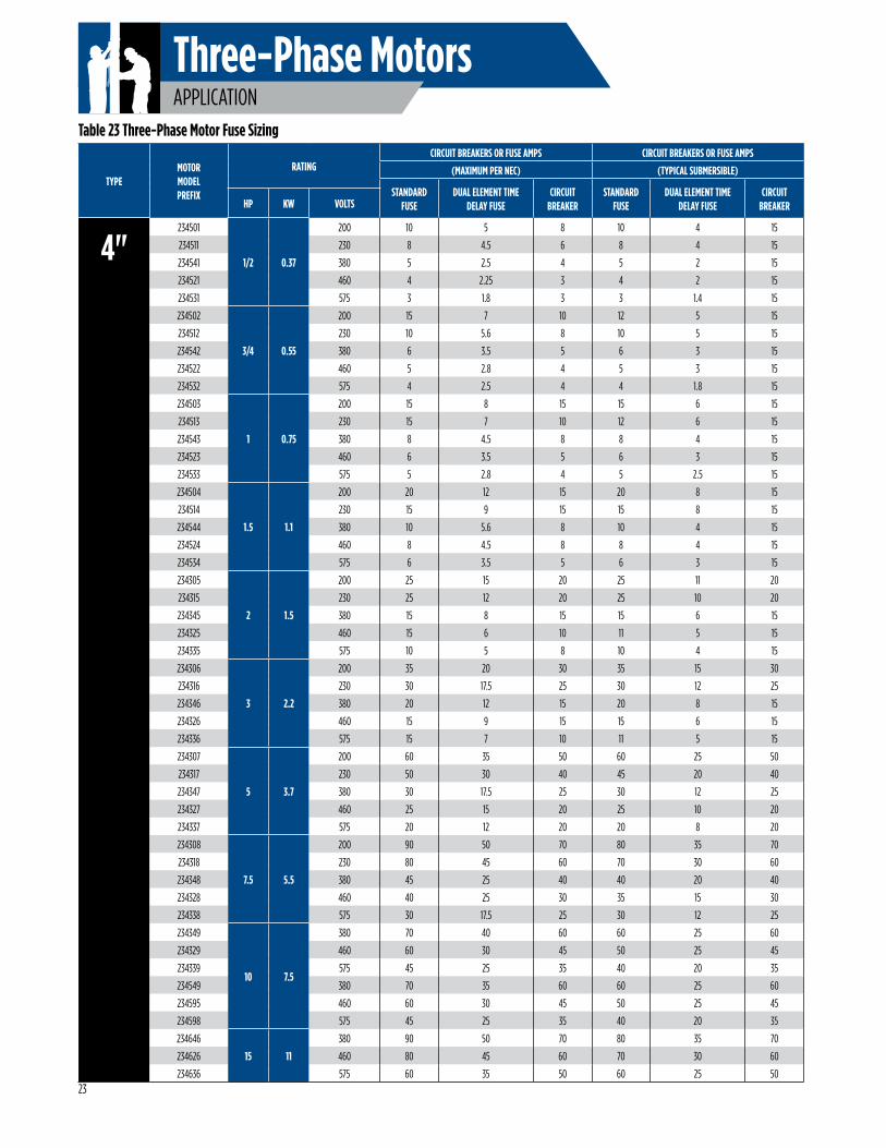
Three-Phase MotorsAPPLICATION
Table 23 Three-Phase Motor Fuse Sizing
TYPEMOTOR MODEL PREFIX
RATINGCIRCUIT BREAKERS OR FUSE AMPS CIRCUIT BREAKERS OR FUSE AMPS
(MAXIMUM PER NEC) (TYPICAL SUBMERSIBLE)
STANDARD FUSE
DUAL ELEMENT TIME DELAY FUSE
CIRCUIT BREAKER
STANDARD FUSE
DUAL ELEMENT TIME DELAY FUSE
CIRCUIT BREAKERHP KW VOLTS
4"234501
1/2 0.37
200 10 5 8 10 4 15
234511 230 8 4.5 6 8 4 15
234541 380 5 2.5 4 5 2 15
234521 460 4 2.25 3 4 2 15
234531 575 3 1.8 3 3 1.4 15
234502
3/4 0.55
200 15 7 10 12 5 15
234512 230 10 5.6 8 10 5 15
234542 380 6 3.5 5 6 3 15
234522 460 5 2.8 4 5 3 15
234532 575 4 2.5 4 4 1.8 15
234503
1 0.75
200 15 8 15 15 6 15
234513 230 15 7 10 12 6 15
234543 380 8 4.5 8 8 4 15
234523 460 6 3.5 5 6 3 15
234533 575 5 2.8 4 5 2.5 15
234504
1.5 1.1
200 20 12 15 20 8 15
234514 230 15 9 15 15 8 15
234544 380 10 5.6 8 10 4 15
234524 460 8 4.5 8 8 4 15
234534 575 6 3.5 5 6 3 15
234305
2 1.5
200 25 15 20 25 11 20
234315 230 25 12 20 25 10 20
234345 380 15 8 15 15 6 15
234325 460 15 6 10 11 5 15
234335 575 10 5 8 10 4 15
234306
3 2.2
200 35 20 30 35 15 30
234316 230 30 17.5 25 30 12 25
234346 380 20 12 15 20 8 15
234326 460 15 9 15 15 6 15
234336 575 15 7 10 11 5 15
234307
5 3.7
200 60 35 50 60 25 50
234317 230 50 30 40 45 20 40
234347 380 30 17.5 25 30 12 25
234327 460 25 15 20 25 10 20
234337 575 20 12 20 20 8 20
234308
7.5 5.5
200 90 50 70 80 35 70
234318 230 80 45 60 70 30 60
234348 380 45 25 40 40 20 40
234328 460 40 25 30 35 15 30
234338 575 30 17.5 25 30 12 25
234349
10 7.5
380 70 40 60 60 25 60
234329 460 60 30 45 50 25 45
234339 575 45 25 35 40 20 35
234549 380 70 35 60 60 25 60
234595 460 60 30 45 50 25 45
234598 575 45 25 35 40 20 35
234646
15 11
380 90 50 70 80 35 70
234626 460 80 45 60 70 30 60
234636 575 60 35 50 60 25 5023
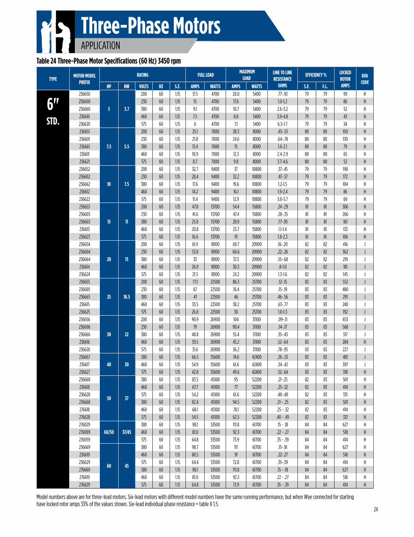
Three-Phase MotorsAPPLICATION
Model numbers above are for three-lead motors. Six-lead motors with different model numbers have the same running performance, but when Wye connected for starting have locked rotor amps 33% of the values shown. Six-lead individual phase resistance = table X 1.5.
Table 24 Three-Phase Motor Specifications (60 Hz) 3450 rpm
TYPEMOTOR MODEL
PREFIXRATING FULL LOAD
MAXIMUM LOAD
LINE TO LINE RESISTANCE
OHMS
EFFICIENCY % LOCKED ROTOR AMPS
KVA CODE
HP KW VOLTS HZ S.F. AMPS WATTS AMPS WATTS S.F. F.L.
6"STD.
236650
5 3.7
200 60 1.15 17.5 4700 20.0 5400 .77-.93 79 79 99 H236600 230 60 1.15 15 4700 17.6 5400 1.0-1.2 79 79 86 H236660 380 60 1.15 9.1 4700 10.7 5400 2.6-3.2 79 79 52 H236610 460 60 1.15 7.5 4700 8.8 5400 3.9-4.8 79 79 43 H236620 575 60 1.15 6 4700 7.1 5400 6.3-7.7 79 79 34 H236651
7.5 5.5
200 60 1.15 25.1 7000 28.3 8000 .43-.53 80 80 150 H236601 230 60 1.15 21.8 7000 24.6 8000 .64-.78 80 80 130 H236661 380 60 1.15 13.4 7000 15 8000 1.6-2.1 80 80 79 H236611 460 60 1.15 10.9 7000 12.3 8000 2.4-2.9 80 80 65 H236621 575 60 1.15 8.7 7000 9.8 8000 3.7-4.6 80 80 52 H236652
10 7.5
200 60 1.15 32.7 9400 37 10800 .37-.45 79 79 198 H236602 230 60 1.15 28.4 9400 32.2 10800 .47-.57 79 79 172 H236662 380 60 1.15 17.6 9400 19.6 10800 1.2-1.5 79 79 104 H236612 460 60 1.15 14.2 9400 16.1 10800 1.9-2.4 79 79 86 H236622 575 60 1.15 11.4 9400 12.9 10800 3.0-3.7 79 79 69 H236653
15 11
200 60 1.15 47.8 13700 54.4 15800 .24-.29 81 81 306 H236603 230 60 1.15 41.6 13700 47.4 15800 .28-.35 81 81 266 H236663 380 60 1.15 25.8 13700 28.9 15800 .77-.95 81 81 161 H236613 460 60 1.15 20.8 13700 23.7 15800 1.1-1.4 81 81 133 H236623 575 60 1.15 16.6 13700 19 15800 1.8-2.3 81 81 106 H236654
20 15
200 60 1.15 61.9 18100 69.7 20900 .16-.20 82 82 416 J236604 230 60 1.15 53.8 18100 60.6 20900 .22-.26 82 82 362 J236664 380 60 1.15 33 18100 37.3 20900 .55-.68 82 82 219 J236614 460 60 1.15 26.9 18100 30.3 20900 .8-1.0 82 82 181 J236624 575 60 1.15 21.5 18100 24.2 20900 1.3-1.6 82 82 145 J236655
25 18.5
200 60 1.15 77.1 22500 86.3 25700 .12-.15 83 83 552 J236605 230 60 1.15 67 22500 76.4 25700 .15-.19 83 83 480 J236665 380 60 1.15 41 22500 46 25700 .46-.56 83 83 291 J236615 460 60 1.15 33.5 22500 38.2 25700 .63-.77 83 83 240 J236625 575 60 1.15 26.8 22500 30 25700 1.0-1.3 83 83 192 J236656
30 22
200 60 1.15 90.9 26900 104 31100 .09-.11 83 83 653 J236606 230 60 1.15 79 26900 90.4 31100 .14-.17 83 83 568 J236666 380 60 1.15 48.8 26900 55.4 31100 .35-.43 83 83 317 J236616 460 60 1.15 39.5 26900 45.2 31100 .52-.64 83 83 284 H236626 575 60 1.15 31.6 26900 36.2 31100 .78-.95 83 83 227 J236667
40 30380 60 1.15 66.5 35600 74.6 42400 .26-.33 83 83 481 J
236617 460 60 1.15 54.9 35600 61.6 42400 .34-.42 83 83 397 J236627 575 60 1.15 42.8 35600 49.6 42400 .52-.64 83 83 318 H236668
50 37
380 60 1.15 83.5 45100 95 52200 .21-.25 82 83 501 H236618 460 60 1.15 67.7 45100 77 52200 .25-.32 82 83 414 H236628 575 60 1.15 54.2 45100 61.6 52200 .40-.49 82 83 331 H276668 380 60 1.15 82.4 45100 94.5 52200 .21 - .25 82 83 501 H276618 460 60 1.15 68.1 45100 78.1 52200 .25 - .32 82 83 414 H276628 575 60 1.15 54.5 45100 62.5 52200 .40 - .49 82 83 331 H276029
60/50 37/45380 60 1.15 98.1 53500 111.8 61700 .15 - .18 84 84 627 H
276009 460 60 1.15 81.0 53500 92.3 61700 .22 - .27 84 84 518 H276059 575 60 1.15 64.8 53500 73.9 61700 .35 - .39 84 84 414 H236669
60 45
380 60 1.15 98.7 53500 111 61700 .15-.18 84 84 627 H236619 460 60 1.15 80.5 53500 91 61700 .22-.27 84 84 518 H236629 575 60 1.15 64.4 53500 72.8 61700 .35-.39 84 84 414 H276669 380 60 1.15 98.1 53500 111.8 61700 .15 - .18 84 84 627 H276619 460 60 1.15 81.0 53500 92.3 61700 .22 - .27 84 84 518 H276629 575 60 1.15 64.8 53500 73.9 61700 .35 - .39 84 84 414 H
24
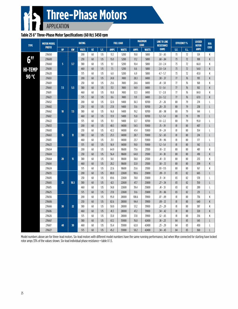
Three-Phase MotorsAPPLICATION
TYPEMOTOR MODEL
PREFIXRATING FULL LOAD
MAXIMUM LOAD
LINE TO LINE RESISTANCE
OHMS
EFFICIENCY % LOCKED ROTOR AMPS
KVA CODE
HP KW VOLTS HZ S.F. AMPS WATTS AMPS WATTS S.F. F.L.
6"HI-TEMP
90 °C
276650
5 3.7
200 60 1.15 17.2 5200 19.8 5800 .53 - .65 73 72 124 K
276600 230 60 1.15 15.0 5200 17.2 5800 .68 - .84 73 72 108 K
276660 380 60 1.15 9.1 5200 10.4 5800 2.0 - 2.4 73 72 66.0 K
276610 460 60 1.15 7.5 5200 8.6 5800 2.8 - 3.4 73 72 54.0 K
276620 575 60 1.15 6.0 5200 6.9 5800 4.7 - 5.7 73 72 43.0 K
276651
7.5 5.5
200 60 1.15 24.8 7400 28.3 8400 .30 - .37 77 76 193 K
276601 230 60 1.15 21.6 7400 24.6 8400 .41 - .50 77 76 168 K
276661 380 60 1.15 13.1 7400 14.9 8400 1.1 - 1.4 77 76 102 K
276611 460 60 1.15 10.8 7400 12.3 8400 1.7 - 2.0 77 76 84.0 K
276621 575 60 1.15 8.6 7400 9.9 8400 2.6 - 3.2 77 76 67.0 K
276652
10 7.5
200 60 1.15 32.0 9400 36.3 10700 .21 - .26 80 79 274 L
276602 230 60 1.15 27.8 9400 31.6 10700 .28 - .35 80 79 238 L
276662 380 60 1.15 16.8 9400 19.2 10700 .80 - .98 80 79 144 L
276612 460 60 1.15 13.9 9400 15.8 10700 1.2 - 1.4 80 79 119 L
276622 575 60 1.15 11.1 9400 12.7 10700 1.8 - 2.2 80 79 95.0 L
276653
15 11
200 60 1.15 48.5 14000 54.5 15900 .15 - .19 81 80 407 L
276603 230 60 1.15 42.2 14000 47.4 15900 .19 - .24 81 80 354 L
276663 380 60 1.15 25.5 14000 28.7 15900 .52 - .65 81 80 214 L
276613 460 60 1.15 21.1 14000 23.7 15900 .78 - .96 81 80 177 L
276623 575 60 1.15 16.9 14000 19.0 15900 1.2 - 1.4 81 80 142 L
276654
20 15
200 60 1.15 64.9 18600 73.6 21300 .10 - .12 80 80 481 K
276604 230 60 1.15 56.4 18600 64.0 21300 .14 - .18 80 80 418 K
276664 380 60 1.15 34.1 18600 38.8 21300 .41 - .51 80 80 253 K
276614 460 60 1.15 28.2 18600 32.0 21300 .58 - .72 80 80 209 K
276624 575 60 1.15 22.6 18600 25.6 21300 .93 - 1.15 80 80 167 K
276655
25 18.5
200 60 1.15 80.0 22600 90.6 25800 .09 - .11 83 82 665 L
276605 230 60 1.15 69.6 22600 78.8 25800 .11 - .14 83 82 578 L
276665 380 60 1.15 42.1 22600 47.7 25800 .27 - .34 83 82 350 L
276615 460 60 1.15 34.8 22600 39.4 25800 .41 - .51 83 82 289 L
276625 575 60 1.15 27.8 22600 31.6 25800 .70 - .86 83 82 231 L
276656
30 22
200 60 1.15 95.0 28000 108.6 31900 .07 - .09 81 80 736 K
276606 230 60 1.15 82.6 28000 94.4 31900 .09 - .12 81 80 640 K
276666 380 60 1.15 50.0 28000 57.2 31900 .23 - .29 81 80 387 K
276616 460 60 1.15 41.3 28000 47.2 31900 .34 - .42 81 80 320 K
276626 575 60 1.15 33.0 28000 37.8 31900 .52 - .65 81 80 256 K
276667
40 30
380 60 1.15 67.2 35900 76.0 42400 .18 - .23 84 83 545 L
276617 460 60 1.15 55.4 35900 62.8 42400 .23 - .29 84 83 450 L
276627 575 60 1.15 45.2 35900 50.2 42400 .34 - .43 84 83 360 L
Table 25 6" Three-Phase Motor Specifications (60 Hz) 3450 rpm
Model numbers above are for three-lead motors. Six-lead motors with different model numbers have the same running performance, but when Wye connected for starting have locked rotor amps 33% of the values shown. Six-lead individual phase resistance = table X 1.5.
25
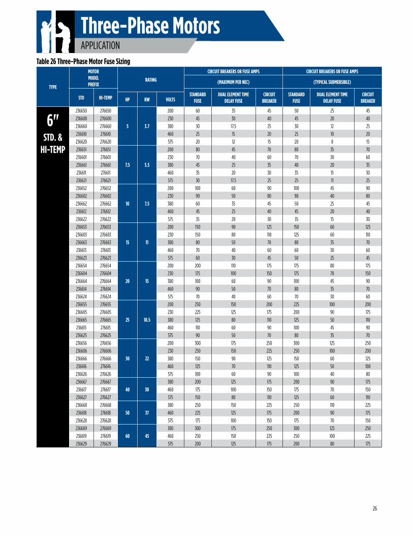
Three-Phase MotorsAPPLICATION
TYPE
MOTOR MODEL PREFIX
RATING
CIRCUIT BREAKERS OR FUSE AMPS CIRCUIT BREAKERS OR FUSE AMPS
(MAXIMUM PER NEC) (TYPICAL SUBMERSIBLE)
STD HI-TEMPSTANDARD
FUSEDUAL ELEMENT TIME
DELAY FUSECIRCUIT
BREAKERSTANDARD
FUSEDUAL ELEMENT TIME
DELAY FUSECIRCUIT
BREAKERHP KW VOLTS
6"STD. &
HI-TEMP
236650 276650
5 3.7
200 60 35 45 50 25 45
236600 276600 230 45 30 40 45 20 40
236660 276660 380 30 17.5 25 30 12 25
236610 276610 460 25 15 20 25 10 20
236620 276620 575 20 12 15 20 8 15
236651 276651
7.5 5.5
200 80 45 70 80 35 70
236601 276601 230 70 40 60 70 30 60
236661 276661 380 45 25 35 40 20 35
236611 276611 460 35 20 30 35 15 30
236621 276621 575 30 17.5 25 25 11 25
236652 276652
10 7.5
200 100 60 90 100 45 90
236602 276602 230 90 50 80 90 40 80
236662 276662 380 60 35 45 50 25 45
236612 276612 460 45 25 40 45 20 40
236622 276622 575 35 20 30 35 15 30
236653 276653
15 11
200 150 90 125 150 60 125
236603 276603 230 150 80 110 125 60 110
236663 276663 380 80 50 70 80 35 70
236613 276613 460 70 40 60 60 30 60
236623 276623 575 60 30 45 50 25 45
236654 276654
20 15
200 200 110 175 175 80 175
236604 276604 230 175 100 150 175 70 150
236664 276664 380 100 60 90 100 45 90
236614 276614 460 90 50 70 80 35 70
236624 276624 575 70 40 60 70 30 60
236655 276655
25 18.5
200 250 150 200 225 100 200
236605 276605 230 225 125 175 200 90 175
236665 276665 380 125 80 110 125 50 110
236615 276615 460 110 60 90 100 45 90
236625 276625 575 90 50 70 80 35 70
236656 276656
30 22
200 300 175 250 300 125 250
236606 276606 230 250 150 225 250 100 200
236666 276666 380 150 90 125 150 60 125
236616 276616 460 125 70 110 125 50 100
236626 276626 575 100 60 90 100 40 80
236667 276667
40 30380 200 125 175 200 90 175
236617 276617 460 175 100 150 175 70 150
236627 276627 575 150 80 110 125 60 110
236668 276668
50 37380 250 150 225 250 110 225
236618 276618 460 225 125 175 200 90 175
236628 276628 575 175 100 150 175 70 150
236669 276669
60 45380 300 175 250 300 125 250
236619 276619 460 250 150 225 250 100 225
236629 276629 575 200 125 175 200 80 175
Table 26 Three-Phase Motor Fuse Sizing
26
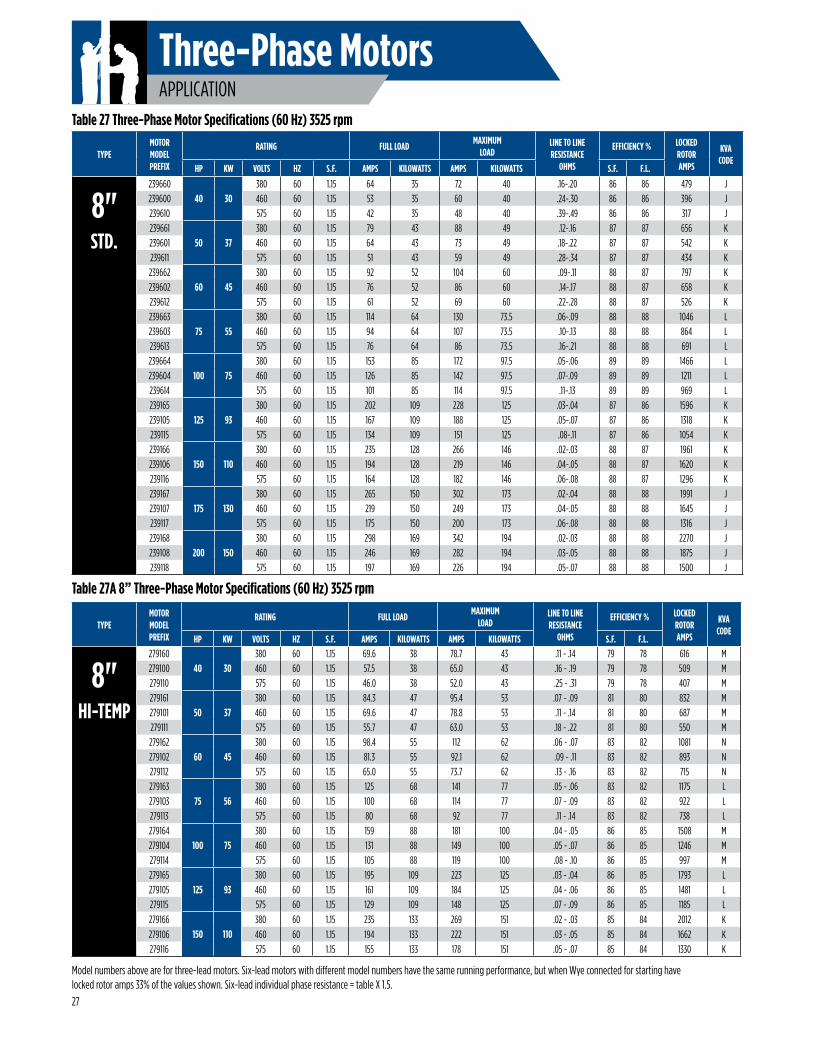
Three-Phase MotorsAPPLICATION
Model numbers above are for three-lead motors. Six-lead motors with different model numbers have the same running performance, but when Wye connected for starting have locked rotor amps 33% of the values shown. Six-lead individual phase resistance = table X 1.5.
Table 27 Three-Phase Motor Specifications (60 Hz) 3525 rpm
TYPEMOTOR MODELPREFIX
RATING FULL LOADMAXIMUM
LOADLINE TO LINE RESISTANCE
OHMS
EFFICIENCY % LOCKED ROTOR AMPS
KVA CODE
HP KW VOLTS HZ S.F. AMPS KILOWATTS AMPS KILOWATTS S.F. F.L.
TYPEMOTOR MODELPREFIX
RATING FULL LOADMAXIMUM
LOADLINE TO LINE RESISTANCE
OHMS
EFFICIENCY % LOCKED ROTOR AMPS
KVA CODE
HP KW VOLTS HZ S.F. AMPS KILOWATTS AMPS KILOWATTS S.F. F.L.
27
8"STD.
23966040 30
380 60 1.15 64 35 72 40 .16-.20 86 86 479 J239600 460 60 1.15 53 35 60 40 .24-.30 86 86 396 J239610 575 60 1.15 42 35 48 40 .39-.49 86 86 317 J239661
50 37380 60 1.15 79 43 88 49 .12-.16 87 87 656 K
239601 460 60 1.15 64 43 73 49 .18-.22 87 87 542 K239611 575 60 1.15 51 43 59 49 .28-.34 87 87 434 K239662
60 45380 60 1.15 92 52 104 60 .09-.11 88 87 797 K
239602 460 60 1.15 76 52 86 60 .14-.17 88 87 658 K239612 575 60 1.15 61 52 69 60 .22-.28 88 87 526 K239663
75 55380 60 1.15 114 64 130 73.5 .06-.09 88 88 1046 L
239603 460 60 1.15 94 64 107 73.5 .10-.13 88 88 864 L239613 575 60 1.15 76 64 86 73.5 .16-.21 88 88 691 L239664
100 75380 60 1.15 153 85 172 97.5 .05-.06 89 89 1466 L
239604 460 60 1.15 126 85 142 97.5 .07-.09 89 89 1211 L239614 575 60 1.15 101 85 114 97.5 .11-.13 89 89 969 L239165
125 93380 60 1.15 202 109 228 125 .03-.04 87 86 1596 K
239105 460 60 1.15 167 109 188 125 .05-.07 87 86 1318 K239115 575 60 1.15 134 109 151 125 .08-.11 87 86 1054 K239166
150 110380 60 1.15 235 128 266 146 .02-.03 88 87 1961 K
239106 460 60 1.15 194 128 219 146 .04-.05 88 87 1620 K239116 575 60 1.15 164 128 182 146 .06-.08 88 87 1296 K239167
175 130380 60 1.15 265 150 302 173 .02-.04 88 88 1991 J
239107 460 60 1.15 219 150 249 173 .04-.05 88 88 1645 J239117 575 60 1.15 175 150 200 173 .06-.08 88 88 1316 J239168
200 150380 60 1.15 298 169 342 194 .02-.03 88 88 2270 J
239108 460 60 1.15 246 169 282 194 .03-.05 88 88 1875 J239118 575 60 1.15 197 169 226 194 .05-.07 88 88 1500 J
8"HI-TEMP
27916040 30
380 60 1.15 69.6 38 78.7 43 .11 - .14 79 78 616 M279100 460 60 1.15 57.5 38 65.0 43 .16 - .19 79 78 509 M279110 575 60 1.15 46.0 38 52.0 43 .25 - .31 79 78 407 M279161
50 37380 60 1.15 84.3 47 95.4 53 .07 - .09 81 80 832 M
279101 460 60 1.15 69.6 47 78.8 53 .11 - .14 81 80 687 M279111 575 60 1.15 55.7 47 63.0 53 .18 - .22 81 80 550 M279162
60 45380 60 1.15 98.4 55 112 62 .06 - .07 83 82 1081 N
279102 460 60 1.15 81.3 55 92.1 62 .09 - .11 83 82 893 N279112 575 60 1.15 65.0 55 73.7 62 .13 - .16 83 82 715 N279163
75 56380 60 1.15 125 68 141 77 .05 - .06 83 82 1175 L
279103 460 60 1.15 100 68 114 77 .07 - .09 83 82 922 L279113 575 60 1.15 80 68 92 77 .11 - .14 83 82 738 L279164
100 75380 60 1.15 159 88 181 100 .04 - .05 86 85 1508 M
279104 460 60 1.15 131 88 149 100 .05 - .07 86 85 1246 M279114 575 60 1.15 105 88 119 100 .08 - .10 86 85 997 M279165
125 93380 60 1.15 195 109 223 125 .03 - .04 86 85 1793 L
279105 460 60 1.15 161 109 184 125 .04 - .06 86 85 1481 L279115 575 60 1.15 129 109 148 125 .07 - .09 86 85 1185 L
279166150 110
380 60 1.15 235 133 269 151 .02 - .03 85 84 2012 K
279106 460 60 1.15 194 133 222 151 .03 - .05 85 84 1662 K279116 575 60 1.15 155 133 178 151 .05 - .07 85 84 1330 K
Table 27A 8” Three-Phase Motor Specifications (60 Hz) 3525 rpm
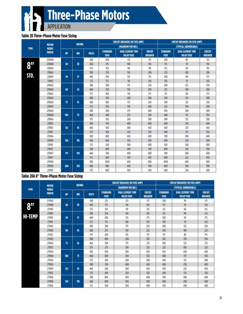
Three-Phase MotorsAPPLICATION
Table 28 Three-Phase Motor Fuse Sizing
TYPEMOTORMODELPREFIX
RATINGCIRCUIT BREAKERS OR FUSE AMPS CIRCUIT BREAKERS OR FUSE AMPS
(MAXIMUM PER NEC) (TYPICAL SUBMERSIBLE)
STANDARD FUSE
DUAL ELEMENT TIME DELAY FUSE
CIRCUIT BREAKER
STANDARD FUSE
DUAL ELEMENT TIME DELAY FUSE
CIRCUIT BREAKER
HP KW VOLTS
8"STD.
23966040 30
380 200 125 175 200 80 175239600 460 175 100 150 175 70 150239610 575 150 80 110 125 60 110239661
50 37380 250 150 200 225 100 200
239601 460 200 125 175 200 80 175239611 575 175 90 150 150 70 150239662
60 45380 300 175 250 300 125 250
239602 460 250 150 200 225 100 200239612 575 200 110 175 175 80 175239663
75 55380 350 200 300 350 150 300
239603 460 300 175 250 300 125 250239613 575 250 150 200 225 100 200239664
100 75380 500 275 400 450 200 400
239604 460 400 225 350 400 175 350239614 575 350 200 300 300 125 300239165
125 93380 700 400 600 600 250 600
239105 460 500 300 450 500 225 450239115 575 450 250 350 400 175 350239166
150 110380 800 450 600 700 300 600
239106 460 600 350 500 600 250 500239116 575 500 300 400 450 200 400239167
175 130380 800 500 700 800 350 700
239107 460 700 400 600 700 300 600239117 575 600 350 450 600 225 450239168
200 150380 1000 600 800 1000 400 800
239108 460 800 450 700 800 350 700239118 575 600 350 500 600 250 500
TYPEMOTORMODELPREFIX
RATINGCIRCUIT BREAKERS OR FUSE AMPS CIRCUIT BREAKERS OR FUSE AMPS
(MAXIMUM PER NEC) (TYPICAL SUBMERSIBLE)
STANDARD FUSE
DUAL ELEMENT TIME DELAY FUSE
CIRCUIT BREAKER
STANDARD FUSE
DUAL ELEMENT TIME DELAY FUSE
CIRCUIT BREAKER
HP KW VOLTS
8"HI-TEMP
27916040 30
380 225 125 175 200 90 175279100 460 175 110 150 175 70 150279110 575 150 90 125 125 60 125279161
50 37380 250 150 225 225 110 225
279101 460 200 125 175 200 90 175279111 575 175 100 150 150 70 150279162
60 45380 300 175 250 300 125 250
279102 460 275 150 225 250 100 225279112 575 200 125 175 175 80 175279163
75 56380 400 200 350 350 150 350
279103 460 300 175 275 300 125 275279113 575 275 150 225 225 100 225279164
100 75380 500 300 450 450 200 450
279104 460 400 250 350 400 175 350279114 575 350 200 300 300 125 300279165
125 93380 700 400 600 600 250 600
279105 460 500 300 450 500 225 450279115 575 450 250 350 400 175 350279166
150 110380 800 450 600 700 300 600
279106 460 600 350 500 600 250 500279116 575 500 300 400 450 200 400
Table 28A 8" Three-Phase Motor Fuse Sizing
28
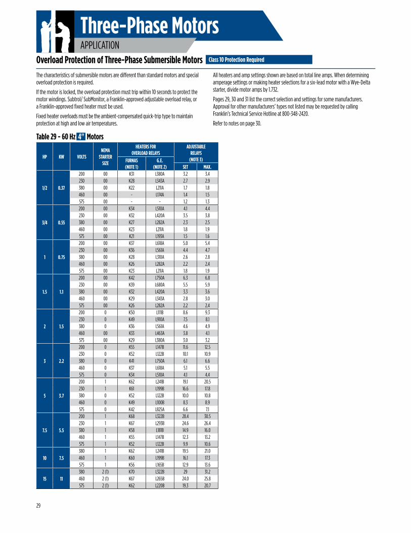
Three-Phase MotorsAPPLICATION
Overload Protection of Three-Phase Submersible MotorsThe characteristics of submersible motors are different than standard motors and special overload protection is required.
If the motor is locked, the overload protection must trip within 10 seconds to protect the motor windings. Subtrol/ SubMonitor, a Franklin-approved adjustable overload relay, or a Franklin-approved fixed heater must be used.
Fixed heater overloads must be the ambient-compensated quick-trip type to maintain protection at high and low air temperatures.
All heaters and amp settings shown are based on total line amps. When determining amperage settings or making heater selections for a six-lead motor with a Wye-Delta starter, divide motor amps by 1.732.
Pages 29, 30 and 31 list the correct selection and settings for some manufacturers. Approval for other manufacturers’ types not listed may be requested by calling Franklin’s Technical Service Hotline at 800-348-2420.
Refer to notes on page 30.
HP KW VOLTSNEMA
STARTERSIZE
HEATERS FOROVERLOAD RELAYS
ADJUSTABLERELAYS
(NOTE 3)FURNAS(NOTE 1)
G.E.(NOTE 2) SET MAX.
1/2 0.37
200 00 K31 L380A 3.2 3.4230 00 K28 L343A 2.7 2.9380 00 K22 L211A 1.7 1.8460 00 - L174A 1.4 1.5575 00 - - 1.2 1.3
3/4 0.55
200 00 K34 L510A 4.1 4.4230 00 K32 L420A 3.5 3.8380 00 K27 L282A 2.3 2.5460 00 K23 L211A 1.8 1.9575 00 K21 L193A 1.5 1.6
1 0.75
200 00 K37 L618A 5.0 5.4230 00 K36 L561A 4.4 4.7380 00 K28 L310A 2.6 2.8460 00 K26 L282A 2.2 2.4575 00 K23 L211A 1.8 1.9
1.5 1.1
200 00 K42 L750A 6.3 6.8230 00 K39 L680A 5.5 5.9380 00 K32 L420A 3.3 3.6460 00 K29 L343A 2.8 3.0575 00 K26 L282A 2.2 2.4
2 1.5
200 0 K50 L111B 8.6 9.3230 0 K49 L910A 7.5 8.1380 0 K36 L561A 4.6 4.9460 00 K33 L463A 3.8 4.1575 00 K29 L380A 3.0 3.2
3 2.2
200 0 K55 L147B 11.6 12.5230 0 K52 L122B 10.1 10.9380 0 K41 L750A 6.1 6.6460 0 K37 L618A 5.1 5.5575 0 K34 L510A 4.1 4.4
5 3.7
200 1 K62 L241B 19.1 20.5230 1 K61 L199B 16.6 17.8380 0 K52 L122B 10.0 10.8460 0 K49 L100B 8.3 8.9575 0 K42 L825A 6.6 7.1
7.5 5.5
200 1 K68 L322B 28.4 30.5230 1 K67 L293B 24.6 26.4380 1 K58 L181B 14.9 16.0460 1 K55 L147B 12.3 13.2575 1 K52 L122B 9.9 10.6
10 7.5380 1 K62 L241B 19.5 21.0460 1 K60 L199B 16.1 17.3575 1 K56 L165B 12.9 13.6
15 11380 2 (1) K70 L322B 29 31.2460 2 (1) K67 L265B 24.0 25.8575 2 (1) K62 L220B 19.3 20.7
Class 10 Protection Required
Table 29 - 60 Hz 4" Motors
29
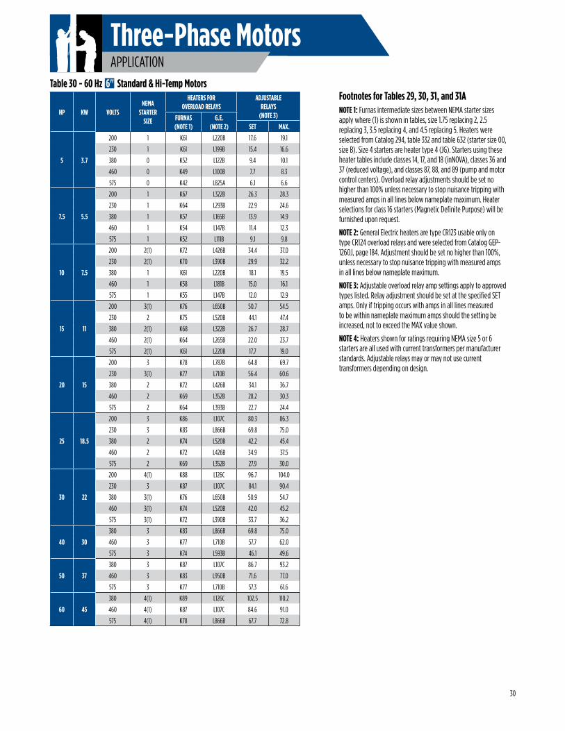
Three-Phase MotorsAPPLICATION
Footnotes for Tables 29, 30, 31, and 31A NOTE 1: Furnas intermediate sizes between NEMA starter sizes apply where (1) is shown in tables, size 1.75 replacing 2, 2.5 replacing 3, 3.5 replacing 4, and 4.5 replacing 5. Heaters were selected from Catalog 294, table 332 and table 632 (starter size 00, size B). Size 4 starters are heater type 4 (JG). Starters using these heater tables include classes 14, 17, and 18 (inNOVA), classes 36 and 37 (reduced voltage), and classes 87, 88, and 89 (pump and motor control centers). Overload relay adjustments should be set no higher than 100% unless necessary to stop nuisance tripping with measured amps in all lines below nameplate maximum. Heater selections for class 16 starters (Magnetic Definite Purpose) will be furnished upon request.
NOTE 2: General Electric heaters are type CR123 usable only on type CR124 overload relays and were selected from Catalog GEP-126OJ, page 184. Adjustment should be set no higher than 100%, unless necessary to stop nuisance tripping with measured amps in all lines below nameplate maximum.
NOTE 3: Adjustable overload relay amp settings apply to approved types listed. Relay adjustment should be set at the specified SET amps. Only if tripping occurs with amps in all lines measured to be within nameplate maximum amps should the setting be increased, not to exceed the MAX value shown.
NOTE 4: Heaters shown for ratings requiring NEMA size 5 or 6 starters are all used with current transformers per manufacturer standards. Adjustable relays may or may not use current transformers depending on design.
HP KW VOLTSNEMA
STARTERSIZE
HEATERS FOROVERLOAD RELAYS
ADJUSTABLERELAYS
(NOTE 3)FURNAS(NOTE 1)
G.E.(NOTE 2) SET MAX.
5 3.7
200 1 K61 L220B 17.6 19.1
230 1 K61 L199B 15.4 16.6
380 0 K52 L122B 9.4 10.1
460 0 K49 L100B 7.7 8.3
575 0 K42 L825A 6.1 6.6
7.5 5.5
200 1 K67 L322B 26.3 28.3
230 1 K64 L293B 22.9 24.6
380 1 K57 L165B 13.9 14.9
460 1 K54 L147B 11.4 12.3
575 1 K52 L111B 9.1 9.8
10 7.5
200 2(1) K72 L426B 34.4 37.0
230 2(1) K70 L390B 29.9 32.2
380 1 K61 L220B 18.1 19.5
460 1 K58 L181B 15.0 16.1
575 1 K55 L147B 12.0 12.9
15 11
200 3(1) K76 L650B 50.7 54.5
230 2 K75 L520B 44.1 47.4
380 2(1) K68 L322B 26.7 28.7
460 2(1) K64 L265B 22.0 23.7
575 2(1) K61 L220B 17.7 19.0
20 15
200 3 K78 L787B 64.8 69.7
230 3(1) K77 L710B 56.4 60.6
380 2 K72 L426B 34.1 36.7
460 2 K69 L352B 28.2 30.3
575 2 K64 L393B 22.7 24.4
25 18.5
200 3 K86 L107C 80.3 86.3
230 3 K83 L866B 69.8 75.0
380 2 K74 L520B 42.2 45.4
460 2 K72 L426B 34.9 37.5
575 2 K69 L352B 27.9 30.0
30 22
200 4(1) K88 L126C 96.7 104.0
230 3 K87 L107C 84.1 90.4
380 3(1) K76 L650B 50.9 54.7
460 3(1) K74 L520B 42.0 45.2
575 3(1) K72 L390B 33.7 36.2
40 30
380 3 K83 L866B 69.8 75.0
460 3 K77 L710B 57.7 62.0
575 3 K74 L593B 46.1 49.6
50 37
380 3 K87 L107C 86.7 93.2
460 3 K83 L950B 71.6 77.0
575 3 K77 L710B 57.3 61.6
60 45
380 4(1) K89 L126C 102.5 110.2
460 4(1) K87 L107C 84.6 91.0
575 4(1) K78 L866B 67.7 72.8
Table 30 - 60 Hz 6" Standard & Hi-Temp Motors
30
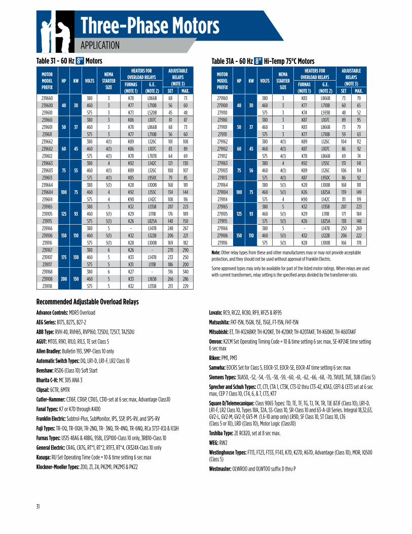
Three-Phase MotorsAPPLICATION
Advance Controls: MDR3 Overload
AEG Series: B17S, B27S, B27-2
ABB Type: RVH 40, RVH65, RVP160, T25DU, T25CT, TA25DU
AGUT: MT03, R1K1, R1L0, R1L3, TE set Class 5
Allen Bradley: Bulletin 193, SMP-Class 10 only
Automatic Switch Types: DQ, LR1-D, LR1-F, LR2 Class 10
Benshaw: RSD6 (Class 10) Soft Start
Bharita C-H: MC 305 ANA 3
Clipsal: 6CTR, 6MTR
Cutler-Hammer: C316F, C316P, C316S, C310-set at 6 sec max, Advantage Class10
Fanal Types: K7 or K7D through K400
Franklin Electric: Subtrol-Plus, SubMonitor, IPS, SSP, IPS-RV, and SPS-RV
Fuji Types: TR-OQ, TR-OQH, TR-2NQ, TR- 3NQ, TR-4NQ, TR-6NQ, RCa 3737-ICQ & ICQH
Furnas Types: US15 48AG & 48BG, 958L, ESP100-Class 10 only, 3RB10-Class 10
General Electric: CR4G, CR7G, RT*1, RT*2, RTF3, RT*4, CR324X-Class 10 only
Kasuga: RU Set Operating Time Code = 10 & time setting 6 sec max
Klockner-Moeller Types: ZOO, Z1, Z4, PKZM1, PKZM3 & PKZ2
Recommended Adjustable Overload Relays
Note: Other relay types from these and other manufacturers may or may not provide acceptable protection, and they should not be used without approval of Franklin Electric.
Some approved types may only be available for part of the listed motor ratings. When relays are used with current transformers, relay setting is the specified amps divided by the transformer ratio.
MOTOR MODEL PREFIX
HP KW VOLTSNEMA
STARTER SIZE
HEATERS FOR OVERLOAD RELAYS
ADJUSTABLERELAYS
(NOTE 3)FURNAS(NOTE 1)
G.E.(NOTE 2) SET MAX.
23966040 30
380 3 K78 L866B 68 73239600 460 3 K77 L710B 56 60239610 575 3 K73 L520B 45 48239661
50 37380 3 K86 L107C 81 87
239601 460 3 K78 L866B 68 73239611 575 3 K77 L710B 56 60239662
60 45380 4(1) K89 L126C 101 108
239602 460 4(1) K86 L107C 83 89239612 575 4(1) K78 L787B 64 69239663
75 55380 4 K92 L142C 121 130
239603 460 4(1) K89 L126C 100 107239613 575 4(1) K85 L950C 79 85239664
100 75380 5(1) K28 L100B 168 181
239604 460 4 K92 L155C 134 144239614 575 4 K90 L142C 108 116239165
125 93380 5 K32 L135B 207 223
239105 460 5(1) K29 L111B 176 189239115 575 5(1) K26 L825A 140 150239166
150 110380 5 - L147B 248 267
239106 460 5(1) K32 L122B 206 221239116 575 5(1) K28 L100B 169 182239167
175 130380 6 K26 - 270 290
239107 460 5 K33 L147B 233 250239117 575 5 K31 L111B 186 200239168
200 150380 6 K27 - 316 340
239108 460 5 K33 L165B 266 286239118 575 5 K32 L135B 213 229
Table 31 - 60 Hz 8" Motors
MOTOR MODEL PREFIX
HP KW VOLTSNEMA
STARTERSIZE
HEATERS FOR OVERLOAD RELAYS
ADJUSTABLERELAYS
(NOTE 3)FURNAS(NOTE 1)
G.E.(NOTE 2) SET MAX.
27916040 30
380 3 K83 L866B 73 79279100 460 3 K77 L710B 60 65279110 575 3 K74 L593B 48 52279161
50 37380 3 K87 L107C 89 95
279101 460 3 K83 L866B 73 79279111 575 3 K77 L710B 59 63279162
60 45380 4(1) K89 L126C 104 112
279102 460 4(1) K87 L107C 86 92279112 575 4(1) K78 L866B 69 74279163
75 56380 4 K92 L155C 131 141
279103 460 4(1) K89 L126C 106 114279113 575 4(1) K87 L950C 86 92279164
100 75380 5(1) K28 L100B 168 181
279104 460 5(1) K26 L825A 139 149279114 575 4 K90 L142C 111 119279165
125 93380 5 K32 L135B 207 223
279105 460 5(1) K29 L111B 171 184279115 575 5(1) K26 L825A 138 148279166
150 110380 5 - L147B 250 269
279106 460 5(1) K32 L122B 206 222279116 575 5(1) K28 L100B 166 178
Table 31A - 60 Hz 8" Hi-Temp 75°C Motors
Lovato: RC9, RC22, RC80, RF9, RF25 & RF95
Matsushita: FKT-15N, 15GN, 15E, 15GE, FT-15N, FHT-15N
Mitsubishi: ET, TH-K12ABKP, TH-K20KF, TH-K20KP, TH-K20TAKF, TH-K60KF, TH-K60TAKF
Omron: K2CM Set Operating Timing Code = 10 & time setting 6 sec max, SE-KP24E time setting 6 sec max
Riken: PM1, PM3
Samwha: EOCRS Set for Class 5, EOCR-ST, EOCR-SE, EOCR-AT time setting 6 sec max
Siemens Types: 3UA50, -52, -54, -55, -58, -59, -60, -61, -62, -66, -68, -70, 3VUI3, 3VE, 3UB (Class 5)
Sprecher and Schuh Types: CT, CT1, CTA 1, CT3K, CT3-12 thru CT3-42, KTA3, CEF1 & CET3 set at 6 sec max, CEP 7 Class 10, CT4, 6, & 7, CT3, KT7
Square D/Telemecanique: Class 9065 Types: TD, TE, TF, TG, TJ, TK, TR, TJE &TJF (Class 10), LR1-D, LR1-F, LR2 Class 10, Types 18A, 32A, SS-Class 10, SR-Class 10 and 63-A-LB Series. Integral 18,32,63, GV2-L, GV2-M, GV2-P, GV3-M (1.6-10 amp only) LR9D, SF Class 10, ST Class 10, LT6 (Class 5 or 10), LRD (Class 10), Motor Logic (Class10)
Toshiba Type: 2E RC820, set at 8 sec max.
WEG: RW2
Westinghouse Types: FT13, FT23, FT33, FT43, K7D, K27D, K67D, Advantage (Class 10), MOR, IQ500 (Class 5)
Westmaster: OLWROO and OLWTOO suffix D thru P
31
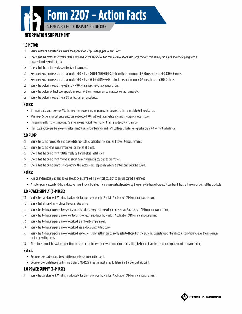
Form 2207 - Action FactsSUBMERSIBLE MOTOR INSTALLATION RECORD
INFORMATION SUPPLEMENT
1.0 MOTOR1.1 Verify motor nameplate data meets the application – hp, voltage, phase, and Hertz.
1.2 Check that the motor shaft rotates freely by hand on the second of two complete rotations. (On large motors, this usually requires a motor coupling with a cheater handle welded to it.)
1.3 Check that the motor lead assembly is not damaged.
1.4 Measure insulation resistance to ground at 500 volts – BEFORE SUBMERGED. It should be a minimum of 200 megohms or 200,000,000 ohms.
1.5 Measure insulation resistance to ground at 500 volts – AFTER SUBMERGED. It should be a minimum of 0.5 megohms or 500,000 ohms.
1.6 Verify the system is operating within the ±10% of nameplate voltage requirement.
1.7 Verify the system will not ever operate in excess of the maximum amps indicated on the nameplate.
1.8 Verify the system is operating at 5% or less current unbalance.
Notice:• If current unbalance exceeds 5%, the maximum operating amps must be derated to the nameplate Full Load Amps.
• Warning - System current unbalance can not exceed 10% without causing heating and mechanical wear issues.
• The submersible motor amperage % unbalance is typically 6x greater than its voltage % unbalance.
• Thus, 0.8% voltage unbalance = greater than 5% current unbalance, and 1.7% voltage unbalance = greater than 10% current unbalance.
2.0 PUMP2.1 Verify the pump nameplate and curve data meets the application hp, rpm, and flow/TDH requirements.
2.2 Verify the pump NPSH requirement will be met at all times.
2.3 Check that the pump shaft rotates freely by hand before installation.
2.4 Check that the pump shaft moves up about ¼ inch when it is coupled to the motor.
2.5 Check that the pump guard is not pinching the motor leads, especially where it enters and exits the guard.
Notice:• Pumps and motors 5 hp and above should be assembled in a vertical position to ensure correct alignment.
• A motor-pump assembly 5 hp and above should never be lifted from a non-vertical position by the pump discharge because it can bend the shaft in one or both of the products.
3.0 POWER SUPPLY (3-PHASE)3.1 Verify the transformer kVA rating is adequate for the motor per the Franklin Application (AIM) manual requirement.
3.2 Verify that all transformers have the same kVA rating.
3.3 Verify the 3-Ph pump panel fuses or its circuit breaker are correctly sized per the Franklin Application (AIM) manual requirement.
3.4 Verify the 3-Ph pump panel motor contactor is correctly sized per the Franklin Application (AIM) manual requirement.
3.5 Verify the 3-Ph pump panel motor overload is ambient compensated.
3.6 Verify the 3-Ph pump panel motor overload has a NEMA Class 10 trip curve.
3.7 Verify the 3-Ph pump panel motor overload heaters or its dial setting are correctly selected based on the system’s operating point and not just arbitrarily set at the maximum motor operating amps.
3.8 At no time should the system operating amps or the motor overload system running point setting be higher than the motor nameplate maximum amp rating.
Notice:• Electronic overloads should be set at the normal system operation point.
• Electronic overloads have a built-in multiplier of 115-125% times the input amps to determine the overload trip point.
4.0 POWER SUPPLY (1-PHASE)4.1 Verify the transformer kVA rating is adequate for the motor per the Franklin Application (AIM) manual requirement.
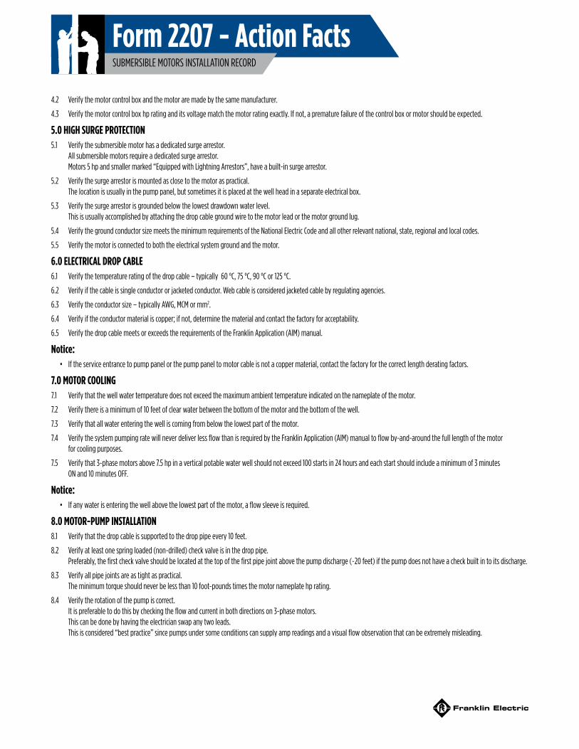
Form 2207 - Action FactsSUBMERSIBLE MOTORS INSTALLATION RECORD
4.2 Verify the motor control box and the motor are made by the same manufacturer.
4.3 Verify the motor control box hp rating and its voltage match the motor rating exactly. If not, a premature failure of the control box or motor should be expected.
5.0 HIGH SURGE PROTECTION5.1 Verify the submersible motor has a dedicated surge arrestor.
All submersible motors require a dedicated surge arrestor. Motors 5 hp and smaller marked “Equipped with Lightning Arrestors”, have a built-in surge arrestor.
5.2 Verify the surge arrestor is mounted as close to the motor as practical. The location is usually in the pump panel, but sometimes it is placed at the well head in a separate electrical box.
5.3 Verify the surge arrestor is grounded below the lowest drawdown water level. This is usually accomplished by attaching the drop cable ground wire to the motor lead or the motor ground lug.
5.4 Verify the ground conductor size meets the minimum requirements of the National Electric Code and all other relevant national, state, regional and local codes.
5.5 Verify the motor is connected to both the electrical system ground and the motor.
6.0 ELECTRICAL DROP CABLE6.1 Verify the temperature rating of the drop cable – typically 60 °C, 75 °C, 90 °C or 125 °C.
6.2 Verify if the cable is single conductor or jacketed conductor. Web cable is considered jacketed cable by regulating agencies.
6.3 Verify the conductor size – typically AWG, MCM or mm2.
6.4 Verify if the conductor material is copper; if not, determine the material and contact the factory for acceptability.
6.5 Verify the drop cable meets or exceeds the requirements of the Franklin Application (AIM) manual.
Notice:• If the service entrance to pump panel or the pump panel to motor cable is not a copper material, contact the factory for the correct length derating factors.
7.0 MOTOR COOLING7.1 Verify that the well water temperature does not exceed the maximum ambient temperature indicated on the nameplate of the motor.
7.2 Verify there is a minimum of 10 feet of clear water between the bottom of the motor and the bottom of the well.
7.3 Verify that all water entering the well is coming from below the lowest part of the motor.
7.4 Verify the system pumping rate will never deliver less flow than is required by the Franklin Application (AIM) manual to flow by-and-around the full length of the motor for cooling purposes.
7.5 Verify that 3-phase motors above 7.5 hp in a vertical potable water well should not exceed 100 starts in 24 hours and each start should include a minimum of 3 minutes ON and 10 minutes OFF.
Notice:• If any water is entering the well above the lowest part of the motor, a flow sleeve is required.
8.0 MOTOR-PUMP INSTALLATION8.1 Verify that the drop cable is supported to the drop pipe every 10 feet.
8.2 Verify at least one spring loaded (non-drilled) check valve is in the drop pipe. Preferably, the first check valve should be located at the top of the first pipe joint above the pump discharge (~20 feet) if the pump does not have a check built in to its discharge.
8.3 Verify all pipe joints are as tight as practical. The minimum torque should never be less than 10 foot-pounds times the motor nameplate hp rating.
8.4 Verify the rotation of the pump is correct. It is preferable to do this by checking the flow and current in both directions on 3-phase motors. This can be done by having the electrician swap any two leads. This is considered “best practice” since pumps under some conditions can supply amp readings and a visual flow observation that can be extremely misleading.
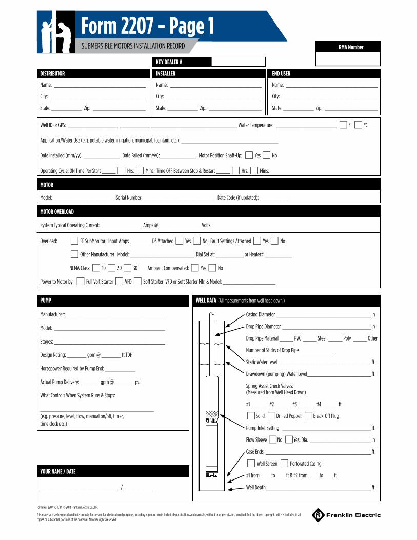
RMA Number
DISTRIBUTOR INSTALLER END USER
Name: _________________________________
City: __________________________________
State: ___________ Zip: ___________________
Name: _________________________________
City: __________________________________
State: ___________ Zip: ___________________
Name: _________________________________
City: __________________________________
State: ___________ Zip: ___________________
Well ID or GPS: __________________ ___________ _______________________________ Water Temperature: ______________________* °F * °C
Application/Water Use (e.g. potable water, irrigation, municipal, fountain, etc.): ___________________________________
Date Installed (mm/yy): _____________ Date Failed (mm/yy):_____________ Motor Position Shaft-Up: * Yes * No
Operating Cycle: ON Time Per Start _____ * Hrs. *Mins. Time OFF Between Stop & Restart _____ * Hrs. *Mins.
MOTOR
Model: ______________________ Serial Number: __________________________ Date Code (if updated): __________
MOTOR OVERLOAD
System Typical Operating Current: _______________ Amps @ _______________ Volts
Overload: * FE SubMonitor Input Amps _______ D3 Attached * Yes * No Fault Settings Attached * Yes * No
* Other Manufacturer Model: _______________________ Dial Set at: __________ or Heater# __________
NEMA Class: * 10 * 20 * 30 Ambient Compensated: * Yes * No
Power to Motor by: * Full Volt Starter * VFD * Soft Starter VFD or Soft Starter Mfr. & Model: ___________________
PUMP
Manufacturer: ____________________________________
Model: ________________________________________
Stages: ________________________________________
Design Rating: _______ gpm @ _______ ft TDH
Horsepower Required by Pump End: ___________
Actual Pump Delivery: _______ gpm @ _______ psi
What Controls When System Runs & Stops:
_________________________________________ (e.g. pressure, level, flow, manual on/off, timer, time clock etc.)
WELL DATA (All measurements from well head down.)
Casing Diameter __________________________________ in
Drop Pipe Diameter ________________________________ in
Drop Pipe Material _____ PVC _____ Steel _____ Poly _____ Other
Number of Sticks of Drop Pipe _____________
Static Water Level _________________________________ ft
Drawdown (pumping) Water Level _______________________ ft
Spring Assist Check Valves: (Measured from Well Head Down)
#1 ______ #2______ #3 ______ #4______ ft
* Solid *Drilled Poppet *Break-Off Plug
Pump Inlet Setting ________________________________ ft
Flow Sleeve * No * Yes, Dia. ______________________ in
Case Ends ______________________________________ ft
* Well Screen * Perforated Casing
#1 from ____to____ft & #2 from ____to____ft
Well Depth ______________________________________ ft
YOUR NAME / DATE
____________________________ / ___________
KEY DEALER #
Form No. 2207 v6 11/14 © 2014 Franklin Electric Co., Inc.
This material may be reproduced in its entirety for personal and educational purposes, including reproduction in technical specifications and manuals, without prior permission, provided that the above copyright notice is included in all copies or substantial portions of the material. All other rights reserved.
Form 2207 - Page 1SUBMERSIBLE MOTORS INSTALLATION RECORD
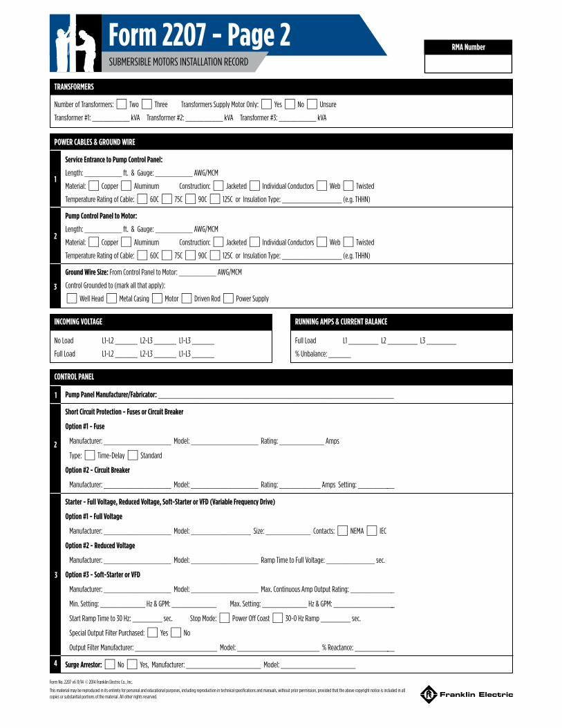
TRANSFORMERS
Number of Transformers: * Two * Three Transformers Supply Motor Only: * Yes * No * Unsure
Transformer #1: __________ kVA Transformer #2: __________ kVA Transformer #3: __________ kVA
POWER CABLES & GROUND WIRE
Service Entrance to Pump Control Panel:
Length: __________ ft. & Gauge: __________ AWG/MCM
Material: * Copper * Aluminum Construction: * Jacketed * Individual Conductors *Web * Twisted
Temperature Rating of Cable: * 60C * 75C * 90C * 125C or Insulation Type: ________________ (e.g. THHN)
Pump Control Panel to Motor:
Length: __________ ft. & Gauge: __________ AWG/MCM
Material: * Copper * Aluminum Construction: * Jacketed * Individual Conductors *Web * Twisted
Temperature Rating of Cable: * 60C * 75C * 90C * 125C or Insulation Type: ________________ (e.g. THHN)
Ground Wire Size: From Control Panel to Motor: __________ AWG/MCM
Control Grounded to (mark all that apply):
*Well Head *Metal Casing *Motor * Driven Rod * Power Supply
INCOMING VOLTAGE
No Load L1-L2 ______ L2-L3 ______ L1-L3 ______
Full Load L1-L2 ______ L2-L3 ______ L1-L3 ______
RUNNING AMPS & CURRENT BALANCE
Full Load L1 ________ L2 ________ L3 ________
% Unbalance: ______
CONTROL PANEL
Pump Panel Manufacturer/Fabricator: _______________________________________________________________
Short Circuit Protection - Fuses or Circuit Breaker
Option #1 - Fuse
Manufacturer: __________________ Model: __________________ Rating: ____________ Amps
Type: * Time-Delay * Standard
Option #2 - Circuit Breaker
Manufacturer: __________________ Model: __________________ Rating: ___________ Amps Setting: __________
Starter - Full Voltage, Reduced Voltage, Soft-Starter or VFD (Variable Frequency Drive)
Option #1 - Full Voltage
Manufacturer: __________________ Model: ________________ Size: ____________ Contacts: * NEMA * IEC
Option #2 - Reduced Voltage
Manufacturer: __________________ Model: __________________ Ramp Time to Full Voltage: _____________ sec.
Option #3 - Soft-Starter or VFD
Manufacturer: __________________ Model: __________________ Max. Continuous Amp Output Rating: ____________
Min. Setting: ____________ Hz & GPM: ____________ Max. Setting: ____________ Hz & GPM: _________________
Start Ramp Time to 30 Hz: ________ sec. Stop Mode: * Power Off Coast * 30-0 Hz Ramp ________ sec.
Special Output Filter Purchased: * Yes * No
Output Filter Manufacturer: ______________________ Model: ______________________ % Reactance: ___________
Surge Arrestor: * No * Yes, Manufacturer: ____________________ Model: ____________________
1
2
3
1
2
3
4
RMA Number
Form No. 2207 v6 11/14 © 2014 Franklin Electric Co., Inc.
This material may be reproduced in its entirety for personal and educational purposes, including reproduction in technical specifications and manuals, without prior permission, provided that the above copyright notice is included in all copies or substantial portions of the material. All other rights reserved.
Form 2207 - Page 2SUBMERSIBLE MOTORS INSTALLATION RECORD
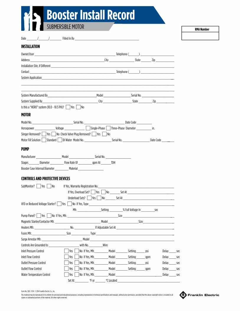
INSTALLATION
Owner/User ________________________________________________ Telephone (______) ____________________
Address ____________________________________________City _______________ State ______ Zip ___________
Installation Site, If Different _________________________________________________________________________
Contact ___________________________________________________ Telephone (______) ____________________
System Application________________________________________________________________________________
___________________________________________________________________________________________
___________________________________________________________________________________________
System Manufactured By_____________________________Model ________________ Serial No. ___________________
System Supplied By_________________________________ City _________________ State ________ Zip ___________
Is this a “HERO” system (10.0 - 10.5 PH)? *Yes *No
Date ______ /______/_______ Filled In By ______________________________________
MOTOR
Model No. ________________________ Serial No. ________________________ Date Code _________
Horsepower ____________ Voltage ____________ *Single-Phase *Three-Phase Diameter _________ in.
Slinger Removed? *Yes *No Check Valve Plug Removed? *Yes *No
Motor Fill Solution *Standard *DI Water Model No. ________________ Serial No. ________________ Date Code _________
PUMP
Manufacturer _______________ Model _______________ Serial No. _______________
Stages ______ Diameter ________ Flow Rate Of ________ gpm At ______TDH
Booster Case Internal Diameter ________ Material _______________
CONTROLS AND PROTECTIVE DEVICES
SubMonitor? *Yes *No If Yes, Warranty Registration No._____________________________________________
If Yes, Overload Set? *Yes *No ______ Set At ____________________________
Underload Sets? *Yes *No ______ Set At _______________________________
VFD or Reduced Voltage Starter? *Yes *No If Yes, Type ___________________________________________________
Mfr. ______________Setting ________% Full Voltage In ________sec
Pump Panel? *Yes *No If Yes, Mfr. ______________________________Size _______________________________
Magnetic Starter/Contactor Mfr. ___________________________ Model __________________Size___________________
Heaters Mfr. _____________________ No. ____________ If Adjustable Set At ___________________________________
Fuses Mfr. ____________________ Size ___________ Type _______________________________________________
Surge Arrestor Mfr. ________________________ Model __________________________________________________
Controls Are Grounded to __________________ with No. ________Wire
Inlet Pressure Control *Yes *No If Yes, Mfr.________ Model _______ Setting _____ psi Delay ____ sec
Inlet Flow Control *Yes *No If Yes, Mfr.________ Model _______ Setting _____ gpm Delay ____ sec
Outlet Pressure Control *Yes *No If Yes, Mfr.________ Model _______ Setting _____ psi Delay ____ sec
Outlet Flow Control *Yes *No If Yes, Mfr.________ Model _______ Setting _____ gpm Delay ____ sec
Water Temperature Control *Yes *No If Yes, Mfr.________ Model ____________________________ Delay ____ sec
Set At ________ °F or ______ °C Located _____________________________________
RMA Number
Form No. 3655 11/14 © 2014 Franklin Electric Co., Inc.
This material may be reproduced in its entirety for personal and educational purposes, including reproduction in technical specifications and manuals, without prior permission, provided that the above copyright notice is included in all copies or substantial portions of the material. All other rights reserved.
Booster Install RecordSUBMERSIBLE MOTOR

INSULATION CHECK
Initial Megs: Motor & Lead Only Black (T1/U1)_________ Yellow (T2/V1)________ Red (T3/W1)_________
Installed Megs: Motor, Lead, & Cable Black (T1/U1)_________ Yellow (T2/V1)________ Red (T3/W1)_________
VOLTAGE TO MOTOR
Non-Operating: B-Y (T1/U1 - T2/V1)________ Y-R (T2/V1 - T3/W1)________ R-B (T3/W1 - T1/U1)________
At Rated Flow of _____________gpm B-Y (T1/U1 - T2/V1)________ Y-R (T2/V1 - T3/W1)________ R-B (T3/W1 - T1/U1)________
At Open Flow _______________gpm B-Y (T1/U1 - T2/V1)________ Y-R (T2/V1 - T3/W1)________ R-B (T3/W1 - T1/U1)________
AMPS TO MOTOR
At Rated Flow of _____________gpm Black (T1/U1)____________ Yellow (T2/V1)___________ Red (T3/W1)____________
At Open Flow _______________gpm Black (T1/U1)____________ Yellow (T2/V1)___________ Red (T3/W1)____________
At Shut-Off* Black (T1/U1)____________ Yellow (T2/V1)___________ Red (T3/W1)____________
*Do NOT run at Shut-Off more than two (2) minutes.
Inlet Pressure _____________psi Outlet Pressure __________psi Water Temperature _______ °F or _______ °C
If you have any questions or problems, call the Franklin Electric Toll-Free Hot Line: 1-800-348-2420
Comments: __________________________________________________________________________________________________________
__________________________________________________________________________________________________________________
__________________________________________________________________________________________________________________
__________________________________________________________________________________________________________________
PLEASE SKETCH THE SYSTEM
Form No. 3655 11/14 © 2014 Franklin Electric Co., Inc.
This material may be reproduced in its entirety for personal and educational purposes, including reproduction in technical specifications and manuals, without prior permission, provided that the above copyright notice is included in all copies or substantial portions of the material. All other rights reserved.
Booster Installation RecordSUBMERSIBLE MOTOR
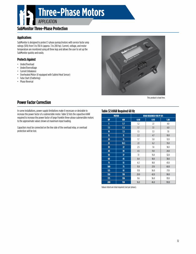
Three-Phase MotorsAPPLICATION
ApplicationsSubMonitor is designed to protect 3-phase pumps/motors with service factor amp ratings (SFA) from 5 to 350 A (approx. 3 to 200 hp). Current, voltage, and motor temperature are monitored using all three legs and allows the user to set up the SubMonitor quickly and easily.
Protects Against• Under/Overload • Under/Overvoltage • Current Unbalance • Overheated Motor (if equipped with Subtrol Heat Sensor) • False Start (Chattering) • Phase Reversal
In some installations, power supply limitations make it necessary or desirable to increase the power factor of a submersible motor. Table 32 lists the capacitive kVAR required to increase the power factor of large Franklin three-phase submersible motors to the approximate values shown at maximum input loading.
Capacitors must be connected on the line side of the overload relay, or overload protection will be lost.
Values listed are total required (not per phase).
Table 32 kVAR Required 60 HzMOTOR KVAR REQUIRED FOR PF OF:
HP KW 0.90 0.95 1.00
5 3.7 1.2 2.1 4.0
7.5 5.5 1.7 3.1 6.0
10 7.5 1.5 3.3 7.0
15 11 2.2 4.7 10.0
20 15 1.7 5.0 12.0
25 18.5 2.1 6.2 15.0
30 22 2.5 7.4 18.0
40 30 4.5 11.0 24.0
50 37 7.1 15.0 32.0
60 45 8.4 18.0 38.0
75 55 6.3 18.0 43.0
100 75 11.0 27.0 60.0
125 93 17.0 36.0 77.0
150 110 20.0 42.0 90.0
175 130 9.6 36.0 93.0
200 150 16.0 46.0 110.0
SubMonitor Three-Phase Protection
Power Factor Correction
32
This product is lead free.
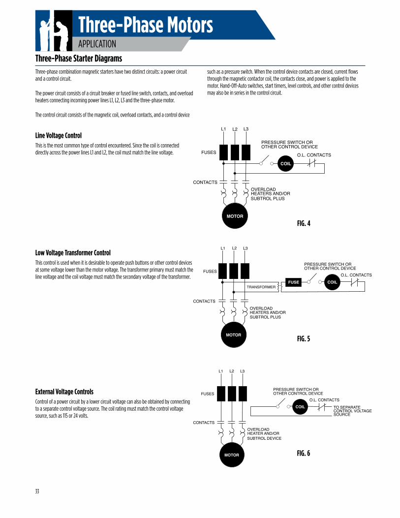
Three-Phase MotorsAPPLICATION
O.L. CONTACTS
PRESSURE SWITCH OROTHER CONTROL DEVICE
COIL
L1 L2 L3
FUSES
CONTACTSOVERLOADHEATERS AND/OR
MOTOR
SUBTROL PLUS
O.L. CONTACTS
PRESSURE SWITCH OROTHER CONTROL DEVICE
L1 L2 L3
FUSES
CONTACTSOVERLOADHEATERS AND/OR
MOTOR
TRANSFORMERCOILFUSE
SUBTROL PLUS
O.L. CONTACTS
PRESSURE SWITCH OROTHER CONTROL DEVICE
L1 L2 L3
FUSES
CONTACTSOVERLOADHEATER AND/OR
MOTOR
COIL TO SEPARATECONTROL VOLTAGESOURCE
SUBTROL DEVICE
Three-phase combination magnetic starters have two distinct circuits: a power circuit and a control circuit.
The power circuit consists of a circuit breaker or fused line switch, contacts, and overload heaters connecting incoming power lines L1, L2, L3 and the three-phase motor.
The control circuit consists of the magnetic coil, overload contacts, and a control device
External Voltage ControlsControl of a power circuit by a lower circuit voltage can also be obtained by connecting to a separate control voltage source. The coil rating must match the control voltage source, such as 115 or 24 volts.
such as a pressure switch. When the control device contacts are closed, current flows through the magnetic contactor coil, the contacts close, and power is applied to the motor. Hand-Off-Auto switches, start timers, level controls, and other control devices may also be in series in the control circuit.
Line Voltage ControlThis is the most common type of control encountered. Since the coil is connected directly across the power lines L1 and L2, the coil must match the line voltage.
Low Voltage Transformer ControlThis control is used when it is desirable to operate push buttons or other control devices at some voltage lower than the motor voltage. The transformer primary must match the line voltage and the coil voltage must match the secondary voltage of the transformer.
FIG. 4
FIG. 5
FIG. 6
Three-Phase Starter Diagrams
33
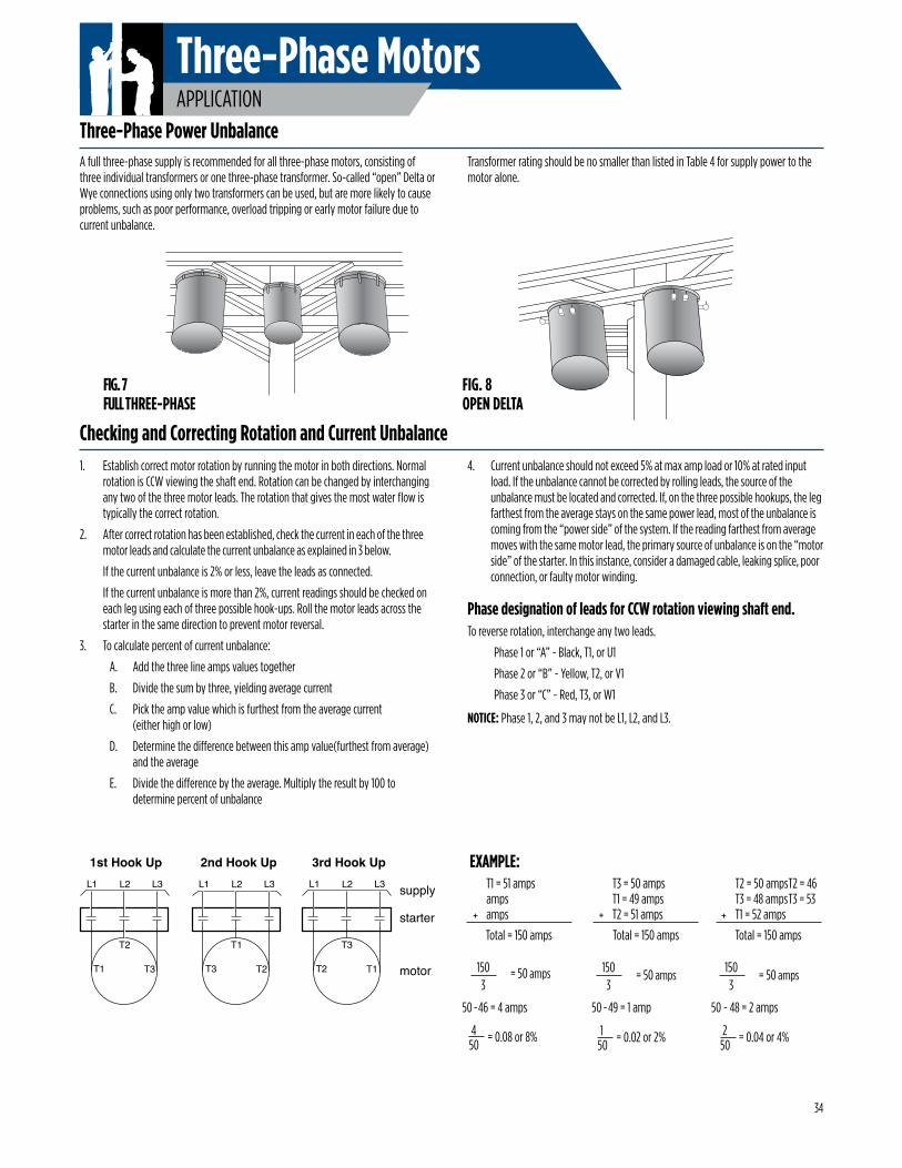
Three-Phase MotorsAPPLICATION
A full three-phase supply is recommended for all three-phase motors, consisting of three individual transformers or one three-phase transformer. So-called “open” Delta or Wye connections using only two transformers can be used, but are more likely to cause problems, such as poor performance, overload tripping or early motor failure due to current unbalance.
Transformer rating should be no smaller than listed in Table 4 for supply power to the motor alone.
1. Establish correct motor rotation by running the motor in both directions. Normal rotation is CCW viewing the shaft end. Rotation can be changed by interchanging any two of the three motor leads. The rotation that gives the most water flow is typically the correct rotation.
2. After correct rotation has been established, check the current in each of the three motor leads and calculate the current unbalance as explained in 3 below.
If the current unbalance is 2% or less, leave the leads as connected.
If the current unbalance is more than 2%, current readings should be checked on each leg using each of three possible hook-ups. Roll the motor leads across the starter in the same direction to prevent motor reversal.
3. To calculate percent of current unbalance:
A. Add the three line amps values together
B. Divide the sum by three, yielding average current
C. Pick the amp value which is furthest from the average current (either high or low)
D. Determine the difference between this amp value(furthest from average) and the average
E. Divide the difference by the average. Multiply the result by 100 to determine percent of unbalance
Checking and Correcting Rotation and Current Unbalance
T2
T1 T3
L1 L2 L3
T1
T3 T2
L1 L2 L3
T3
T2 T1
L1 L2 L3
1st Hook Up 2nd Hook Up 3rd Hook Up
supply
starter
motor
FIG. 7 FULL THREE-PHASE
FIG. 8 OPEN DELTA
150
= 0.02 or 2%
EXAMPLE: T1 = 51 amps T3 = 50 amps T2 = 50 amps T2 = 46
amps T1 = 49 amps T3 = 48 amps T3 = 53 amps T2 = 51 amps T1 = 52 amps
Total = 150 amps Total = 150 amps Total = 150 amps+ + +
50 - 46 = 4 amps 50 - 49 = 1 amp 50 - 48 = 2 amps
250
= 0.04 or 4%
150
3 = 50 amps 150
3 = 50 amps
450
= 0.08 or 8%
150
3 = 50 amps
Three-Phase Power Unbalance
34
4. Current unbalance should not exceed 5% at max amp load or 10% at rated input load. If the unbalance cannot be corrected by rolling leads, the source of the unbalance must be located and corrected. If, on the three possible hookups, the leg farthest from the average stays on the same power lead, most of the unbalance is coming from the “power side” of the system. If the reading farthest from average moves with the same motor lead, the primary source of unbalance is on the “motor side” of the starter. In this instance, consider a damaged cable, leaking splice, poor connection, or faulty motor winding.
Phase designation of leads for CCW rotation viewing shaft end.To reverse rotation, interchange any two leads.
Phase 1 or “A” - Black, T1, or U1
Phase 2 or “B” - Yellow, T2, or V1
Phase 3 or “C” - Red, T3, or W1
NOTICE: Phase 1, 2, and 3 may not be L1, L2, and L3.
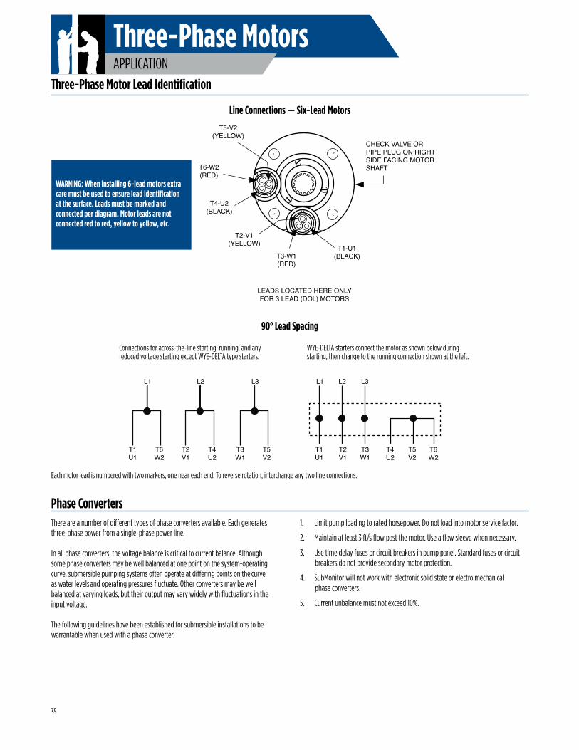
Three-Phase MotorsAPPLICATION
Three-Phase Motor Lead Identification
Each motor lead is numbered with two markers, one near each end. To reverse rotation, interchange any two line connections.
L1
T1U1
T1U1
T6W2
T6W2
L2
T2V1
T2V1
T4U2
T4U2
L3
T3W1
T3W1
T5V2
T5V2
L1 L2 L3
Connections for across-the-line starting, running, and any reduced voltage starting except WYE-DELTA type starters.
WYE-DELTA starters connect the motor as shown below during starting, then change to the running connection shown at the left.
There are a number of different types of phase converters available. Each generates three-phase power from a single-phase power line.
In all phase converters, the voltage balance is critical to current balance. Although some phase converters may be well balanced at one point on the system-operating curve, submersible pumping systems often operate at differing points on the curve as water levels and operating pressures fluctuate. Other converters may be well balanced at varying loads, but their output may vary widely with fluctuations in the input voltage.
The following guidelines have been established for submersible installations to be warrantable when used with a phase converter.
1. Limit pump loading to rated horsepower. Do not load into motor service factor.
2. Maintain at least 3 ft/s flow past the motor. Use a flow sleeve when necessary.
3. Use time delay fuses or circuit breakers in pump panel. Standard fuses or circuit breakers do not provide secondary motor protection.
4. SubMonitor will not work with electronic solid state or electro mechanical phase converters.
5. Current unbalance must not exceed 10%.
T5-V2(YELLOW)
T2-V1(YELLOW)
T4-U2(BLACK)
T1-U1(BLACK)
T6-W2(RED)
T3-W1(RED)
LEADS LOCATED HERE ONLYFOR 3 LEAD (DOL) MOTORS
CHECK VALVE OR PIPE PLUG ON RIGHTSIDE FACING MOTORSHAFT
WARNING: When installing 6-lead motors extra care must be used to ensure lead identification at the surface. Leads must be marked and connected per diagram. Motor leads are not connected red to red, yellow to yellow, etc.
Line Connections — Six-Lead Motors
90° Lead Spacing
Phase Converters
35
Three-Phase MotorsAPPLICATION
All Franklin three-phase submersible motors are suitable for full-voltage starting. Under this condition the motor speed goes from zero to full speed within a half second or less. The motor current goes from zero to locked rotor amps, then drops to running amps at full speed. This may dim lights, cause momentary voltage dips to other electrical equipment, and shock power distribution transformers.
In some cases the power companies may require reduced-voltage starters to limit this voltage dip. There are also times when reduced-voltage starters may be desirable to reduce motor starting torque thus reducing the stress on shafts, couplings, and discharge piping. Reduced-voltage starters also slow the rapid acceleration of the water on start-up to help control upthrust and water hammer.
Reduced-voltage starters may not be required if the maximum recommended cable length is used. With maximum recommended cable length there is a 5% voltage drop in the cable at running amps, resulting in about 20% reduction in starting current and about 36% reduction in starting torque compared to having rated voltage at the motor. This may be enough reduction in starting current so that reduced-voltage starters are not required.
Three-Lead Motors: Autotransformer or solid-state reduced-voltage starters may be used for soft-starting standard three-phase motors.
When autotransformer starters are used, the motor should be supplied with at least 55% of rated voltage to ensure adequate starting torque. Most autotransformer starters have 65% and 80% taps. Setting the taps on these starters depends on the percentage of the maximum allowable cable length used in the system. If the cable length is less than 50% of the maximum allowable, either the 65% or the 80% taps may be used. When the cable length is more than 50% of allowable, the 80% tap should be used.
Six-Lead Motors: Wye-Delta starters are used with six-lead Wye-Delta motors. All
Franklin 6" and 8" three-phase motors are available in six-lead Wye-Delta construction. Consult the factory for details and availability. Part winding starters are not compatible with Franklin Electric submersible motors and should not be used.
Wye-Delta starters of the open-transition type, which momentarily interrupt power during the starting cycle, are not recommended. Closed-transition starters have no interruption of power during the start cycle and can be used with satisfactory results.
Reduced-voltage starters have adjustable settings for acceleration ramp time, typically preset at 30 seconds. They must be adjusted so the motor is at full voltage within THREE SECONDS MAXIMUM to prevent excessive radial and thrust bearing wear.
If Subtrol-Plus or SubMonitor is used the acceleration time must be set to TWO SECONDS MAXIMUM due to the 3 second reaction time of the Subtrol-Plus or SubMonitor.
Solid-state starters AKA soft starts may not be compatible with Subtrol-Plus/SubMonitor. However, in some cases a bypass contactor has been used. Consult the factory for details.
During shutdown, Franklin Electric’s recommendation is for the power to be removed, allowing the pump/motor to coast down. Stopping the motor by ramping down the voltage is possible, but should be limited to three (3) seconds maximum.
Franklin Electric offers three different types of motors for non-vertical applications.
1. The Booster motors are specifically designed for booster applications. They are the “Best Choice” for sealed Reverse Osmosis applications. These motors are the result of two years of focused development and bring additional value and durability to booster module systems. These motors are only available to OEMs or Distributors who have demonstrated capability in Booster Module systems design and operation and adhere to Franklin’s Application Manual requirements.
2. The Hi-Temp motors have many of the internal design features of the Booster motor. It’s additional length allows for higher temperature handling and the Sand Fighter sealing system provides greater abrasion resistance. One or both of these conditions are often experienced in open atmosphere applications such as lakes, ponds, etc.
3. The Standard Vertical Water Well (40-125 hp) motors can be adapted to non-vertical applications when applied per the below guidelines. However, they will be more sensitive to application variances than the other two designs.
All of the above motors must be applied per the guidelines listed below. In addition, for all applications where the motor is applied in a sealed system, a Submersible Motor Booster Installation Record (Form 3655) or its equivalent must be completed at start-up and received by Franklin Electric within 60 days. A sealed system is one where the motor and pump intake are mounted in a sleeve and the water feeding the pump intake is not open to the atmosphere.
Reduced Voltage Starters
Inline Booster Pump Systems
36
Continued on next page
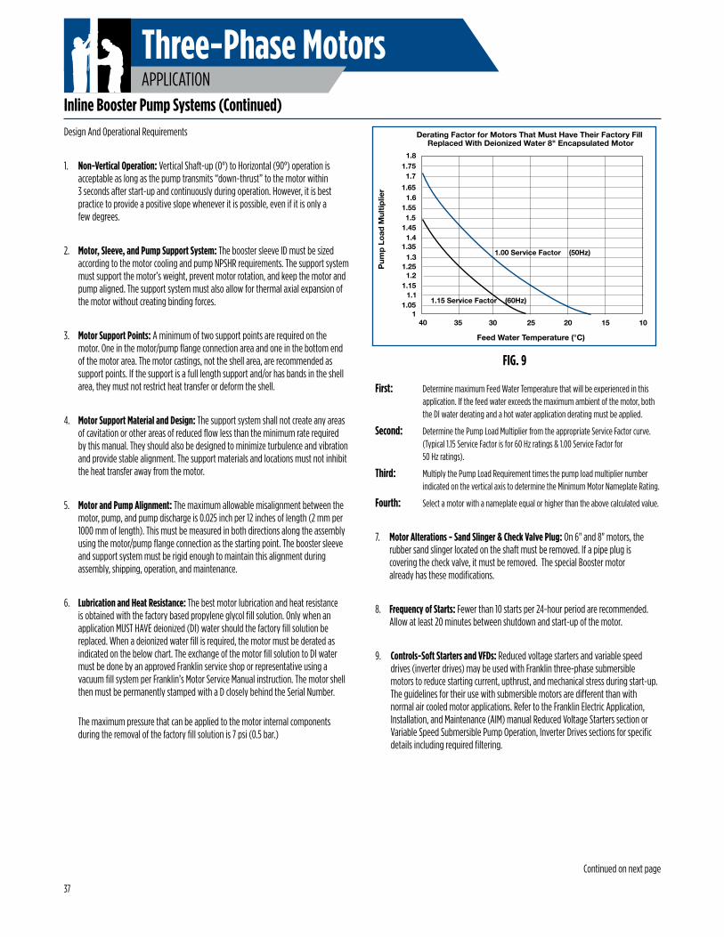
Three-Phase MotorsAPPLICATION
Design And Operational Requirements
1. Non-Vertical Operation: Vertical Shaft-up (0°) to Horizontal (90°) operation is acceptable as long as the pump transmits “down-thrust” to the motor within 3 seconds after start-up and continuously during operation. However, it is best practice to provide a positive slope whenever it is possible, even if it is only a few degrees.
2. Motor, Sleeve, and Pump Support System: The booster sleeve ID must be sized according to the motor cooling and pump NPSHR requirements. The support system must support the motor’s weight, prevent motor rotation, and keep the motor and pump aligned. The support system must also allow for thermal axial expansion of the motor without creating binding forces.
3. Motor Support Points: A minimum of two support points are required on the motor. One in the motor/pump flange connection area and one in the bottom end of the motor area. The motor castings, not the shell area, are recommended as support points. If the support is a full length support and/or has bands in the shell area, they must not restrict heat transfer or deform the shell.
4. Motor Support Material and Design: The support system shall not create any areas of cavitation or other areas of reduced flow less than the minimum rate required by this manual. They should also be designed to minimize turbulence and vibration and provide stable alignment. The support materials and locations must not inhibit the heat transfer away from the motor.
5. Motor and Pump Alignment: The maximum allowable misalignment between the motor, pump, and pump discharge is 0.025 inch per 12 inches of length (2 mm per 1000 mm of length). This must be measured in both directions along the assembly using the motor/pump flange connection as the starting point. The booster sleeve and support system must be rigid enough to maintain this alignment during assembly, shipping, operation, and maintenance.
6. Lubrication and Heat Resistance: The best motor lubrication and heat resistance is obtained with the factory based propylene glycol fill solution. Only when an application MUST HAVE deionized (DI) water should the factory fill solution be replaced. When a deionized water fill is required, the motor must be derated as indicated on the below chart. The exchange of the motor fill solution to DI water must be done by an approved Franklin service shop or representative using a vacuum fill system per Franklin’s Motor Service Manual instruction. The motor shell then must be permanently stamped with a D closely behind the Serial Number.
The maximum pressure that can be applied to the motor internal components during the removal of the factory fill solution is 7 psi (0.5 bar.)
Inline Booster Pump Systems (Continued)
First: Determine maximum Feed Water Temperature that will be experienced in this application. If the feed water exceeds the maximum ambient of the motor, both the DI water derating and a hot water application derating must be applied.
Second: Determine the Pump Load Multiplier from the appropriate Service Factor curve. (Typical 1.15 Service Factor is for 60 Hz ratings & 1.00 Service Factor for 50 Hz ratings).
Third: Multiply the Pump Load Requirement times the pump load multiplier number indicated on the vertical axis to determine the Minimum Motor Nameplate Rating.
Fourth: Select a motor with a nameplate equal or higher than the above calculated value.
7. Motor Alterations - Sand Slinger & Check Valve Plug: On 6" and 8" motors, the rubber sand slinger located on the shaft must be removed. If a pipe plug is covering the check valve, it must be removed. The special Booster motor already has these modifications.
8. Frequency of Starts: Fewer than 10 starts per 24-hour period are recommended. Allow at least 20 minutes between shutdown and start-up of the motor.
9. Controls-Soft Starters and VFDs: Reduced voltage starters and variable speed drives (inverter drives) may be used with Franklin three-phase submersible motors to reduce starting current, upthrust, and mechanical stress during start-up. The guidelines for their use with submersible motors are different than with normal air cooled motor applications. Refer to the Franklin Electric Application, Installation, and Maintenance (AIM) manual Reduced Voltage Starters section or Variable Speed Submersible Pump Operation, Inverter Drives sections for specific details including required filtering.
FIG. 9
1.8
1.7
1.6
1.5
1.4
1.3
1.2
1.1
130 25 20 15 103540
1.75
1.65
1.55
1.45
1.35
1.25
1.15
1.05
1.00 Service Factor (50Hz)
1.15 Service Factor (60Hz)
Derating Factor for Motors That Must Have Their Factory Fill Replaced With Deionized Water 8" Encapsulated Motor
Feed Water Temperature (°C)
Pum
p Lo
ad M
ultip
lier
37
Continued on next page
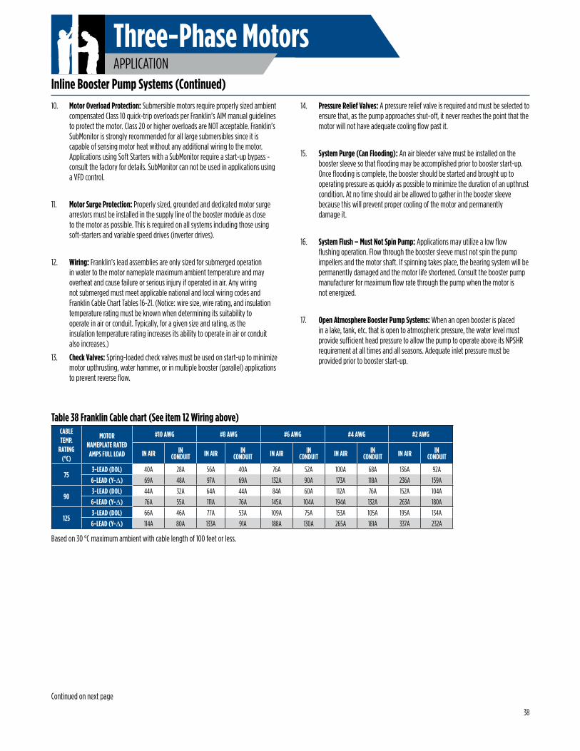
Three-Phase MotorsAPPLICATION
10. Motor Overload Protection: Submersible motors require properly sized ambient compensated Class 10 quick-trip overloads per Franklin’s AIM manual guidelines to protect the motor. Class 20 or higher overloads are NOT acceptable. Franklin’s SubMonitor is strongly recommended for all large submersibles since it is capable of sensing motor heat without any additional wiring to the motor. Applications using Soft Starters with a SubMonitor require a start-up bypass - consult the factory for details. SubMonitor can not be used in applications using a VFD control.
11. Motor Surge Protection: Properly sized, grounded and dedicated motor surge arrestors must be installed in the supply line of the booster module as close to the motor as possible. This is required on all systems including those using soft-starters and variable speed drives (inverter drives).
12. Wiring: Franklin’s lead assemblies are only sized for submerged operation in water to the motor nameplate maximum ambient temperature and may overheat and cause failure or serious injury if operated in air. Any wiring not submerged must meet applicable national and local wiring codes and Franklin Cable Chart Tables 16-21. (Notice: wire size, wire rating, and insulation temperature rating must be known when determining its suitability to operate in air or conduit. Typically, for a given size and rating, as the insulation temperature rating increases its ability to operate in air or conduit also increases.)
13. Check Valves: Spring-loaded check valves must be used on start-up to minimize motor upthrusting, water hammer, or in multiple booster (parallel) applications to prevent reverse flow.
Inline Booster Pump Systems (Continued)14. Pressure Relief Valves: A pressure relief valve is required and must be selected to
ensure that, as the pump approaches shut-off, it never reaches the point that the motor will not have adequate cooling flow past it.
15. System Purge (Can Flooding): An air bleeder valve must be installed on the booster sleeve so that flooding may be accomplished prior to booster start-up. Once flooding is complete, the booster should be started and brought up to operating pressure as quickly as possible to minimize the duration of an upthrust condition. At no time should air be allowed to gather in the booster sleeve because this will prevent proper cooling of the motor and permanently damage it.
16. System Flush – Must Not Spin Pump: Applications may utilize a low flow flushing operation. Flow through the booster sleeve must not spin the pump impellers and the motor shaft. If spinning takes place, the bearing system will be permanently damaged and the motor life shortened. Consult the booster pump manufacturer for maximum flow rate through the pump when the motor is not energized.
17. Open Atmosphere Booster Pump Systems: When an open booster is placed in a lake, tank, etc. that is open to atmospheric pressure, the water level must provide sufficient head pressure to allow the pump to operate above its NPSHR requirement at all times and all seasons. Adequate inlet pressure must be provided prior to booster start-up.
Based on 30 °C maximum ambient with cable length of 100 feet or less.
Table 38 Franklin Cable chart (See item 12 Wiring above)CABLE TEMP.
RATING (°C)
MOTOR NAMEPLATE RATED AMPS FULL LOAD
#10 AWG #8 AWG #6 AWG #4 AWG #2 AWG
IN AIR IN CONDUIT IN AIR IN
CONDUIT IN AIR IN CONDUIT IN AIR IN
CONDUIT IN AIR IN CONDUIT
753-LEAD (DOL) 40A 28A 56A 40A 76A 52A 100A 68A 136A 92A
6-LEAD (Y-∆) 69A 48A 97A 69A 132A 90A 173A 118A 236A 159A
903-LEAD (DOL) 44A 32A 64A 44A 84A 60A 112A 76A 152A 104A
6-LEAD (Y-∆) 76A 55A 111A 76A 145A 104A 194A 132A 263A 180A
1253-LEAD (DOL) 66A 46A 77A 53A 109A 75A 153A 105A 195A 134A
6-LEAD (Y-∆) 114A 80A 133A 91A 188A 130A 265A 181A 337A 232A
38
Continued on next page
Three-Phase MotorsAPPLICATION
Four Continuous Monitoring System Requirements for Sealed Booster Systems.
1. Water Temperature: Feed water on each booster must be continuously monitored and not allowed to exceed the motor nameplate maximum ambient temperature at any time. IF THE INLET TEMPERATURE EXCEEDS THE MOTOR NAMEPLATE MAXIMUM AMBIENT TEMPERATURE, THE SYSTEM MUST SHUTDOWN IMMEDIATELY TO PREVENT PERMANENT MOTOR DAMAGE. If feed water temperatures are expected to be above the allowable temperature, the motor must be derated. See Franklin’s AIM manual Hot Water Applications section for derating guidelines. (The high temperature feed water derating is in addition to the exchange to DI water derating if the motor factory fill solution was exchanged to DI water.)
2. Inlet Pressure: The inlet pressure on each booster module must be continuously monitored. It must always be positive and higher than the NPSHR (Net Positive Suction Head Requirement) of the pump. A minimum of 20 PSIG (1.38 Bar) is required at all times, except for 10 seconds or less when the motor is starting and the system is coming up to pressure. Even during these 10 seconds the pressure must remain positive and be higher than the NPSHR (Net Positive Suction Head Requirement) of the pump.
Inline Booster Pump Systems (Continued)PSIG is the actual value displayed on a pressure gauge in the system piping. PSIG is the pressure above the atmospheric conditions. If at any time these pressure requirements are not being met, the motor must be de-energized immediately to prevent permanent damage to the motor. Once the motor is damaged, it is usually not immediately noticeable, but progresses and results in a premature motor failure weeks or months after the damage occurred. Motors that will be exposed to pressure in excess of 500 psi (34.47 Bar) must undergo special high pressure testing. Consult factory for details and availability.
3. Discharge Flow: The flow rate for each pump must not be allowed to drop below the motor minimum cooling flow requirement. IF THE MOTOR MINIMUM COOLING FLOW REQUIREMENT IS NOT BEING MET FOR MORE THAN 10 SECONDS, THE SYSTEM MUST BE SHUT DOWN IMMEDIATELY TO PREVENT PERMANENT MOTOR DAMAGE.
4. Discharge Pressure: The discharge pressure must be monitored to ensure that a downthrust load toward the motor is present within 3 seconds after start-up and continuously during operation. IF THE MOTOR DISCHARGE PRESSURE IS NOT ADEQUATE TO MEET THIS REQUIREMENT, THE SYSTEM MUST BE SHUT DOWN IMMEDIATELY TO PREVENT PERMANENT MOTOR DAMAGE.
39
Three-Phase MotorsAPPLICATION
40
Variable Frequency Drive Submersible Motor RequirementsFranklin Electric’s three-phase, encapsulated submersible motors can be used with variable frequency drives (VFD) when applied within the guidelines below.
All three-phase, encapsulated submersible motors must have the VFD sized based on the motor’s nameplate maximum amps, not horsepower. The continuous rated amps of the VFD must be equal to or greater than the motor’s nameplate maximum amps or warranty will be void.
Franklin Electric’s single-phase, 2- and 3-wire, encapsulated submersible motors can only be used with the appropriate Franklin constant pressure controller.
Franklin Electric’s submersible motor Application, Installation, Maintenance (AIM) manual should be checked for the latest guidelines and can be found online at www.franklin-electric.com.
WARNING: There is a potential shock hazard from contact with and/or touching the insulated cables connected to the variable frequency drive output anytime the motor has energy applied.
Output Filter Requirement Test:NOTICE: An incoming power supply or line-side filter for the drive does not replace the need for additional output filters.
An output filter is required if the answer is yes to one or both of the items below:#1 - Does the peak voltage at the motor terminals exceed 1000-volts or is the rise time of the VFD's voltage less than 2 micro-seconds? Per NEMA MG 1-2011, the rise time is defined as the time between 10% and 90% of the steady-state voltage (i.e., DC bus voltage).
#2 - Is the motor nameplate voltage more than 379 Volts and is the cable from drive-to-motor more than 50 ft (15.2 m)?
NOTICE:More than 99% of the drives applied on water well submersible motors will require the purchase of additional output filtering based on question #1.
Output filters can be expensive. However, when needed, it is required for the motor to be considered for warranty. Make sure this item is not overlooked when quoting a job.
PWM dV/dt value can be defined as: the rate at which voltage is changing with time or how fast the voltage is accelerating. This information can be supplied by the drive manufacturer or the manufacturer’s drive specification sheet. The dV/dt value cannot be measured with typical field equipment, even when using a true-RMS voltage/amperage multi-meter.
Franklin Electric has a line of VFDs that are specifically designed for Franklin application systems. These VFDs are used in the MonoDrive and SubDrive constant pressure systems. Franklin drive systems have the required additional output filtering installed; however, the SubDrive HPX does not.
Types of Output Filters: A resistor-inductor-capacitor (RLC) filter has both a high pass filter & a low pass filter section and are considered the best practice, but a high pass reactor filter is also acceptable.
Filters should be recommended by the drive manufacturer; for the correct recommendations provide them with answers to all five of the items below.
REQUIRED ITEMS FOR PROPER VFD FILTER SIZING:(1) VFD model (2) Carrier frequency setting (3) Motor nameplate voltage (4) Motor nameplate max amps (5) Cable length from the drive output terminals to the motor
Input Current & Motor Overload Protection:• Motor input current should be set at the system’s typical operating current when running at nameplate rated voltage and frequency (Hz).
• Motor overload protection should be set to trip at 115% of the system’s typical operating current.
• Motor overload protection must trip equal to or faster than NEMA Class 10 motor overload curve requirements.
Motor Maximum Load Limits:• The system must never operate in excess of the motor nameplate maximum amps.
• On 50 Hz motors, nameplate amps are maximum amps as these motors have a 1.0 service factor.
Three-Phase MotorsAPPLICATION
Motor Operating Hertz, Cooling Requirements, and Underload Settings:
• Standard practice for large VFD installations is to limit the operation to 60 Hz max. Operating at greater than 60 Hz requires special system design considerations.
• The motor must never operate below 30 Hz. This is the minimum speed required to provide correct bearing lubrication.
• The motor’s operating speed must always operate so the minimum water flow requirements of 0.5 ft/sec for 6-inch & 8-inch motors and 0.25 ft/sec for 4-inch motors is supplied.
• The motor underload protection is normally set to trip at 80% of the system’s typical operating current. However, the underload trip point must be selected so that minimum flow requirements are always met.
Starting and Stopping Ramp Settings:• The motor must reach or pass the 30 Hz operating speed within 1 second of the motor being energized. If this does not occur, the motor bearings will be damaged and the motor life reduced.
• The best stopping method is to turn power off followed by a natural coast to stop.
• A controlled stop from 30 Hz to 0 Hz is allowed if the time does not exceed 1 second.
Drive Carrier Frequency:• The carrier frequency is set in the field. The drive typically has a selectable range between 2k and 12k Hz. The higher the carrier wave frequency setting, the greater the voltage spikes; the lower the carrier wave frequency setting, the rougher/poorer the shape of the power curve.
• The carrier frequency should be set within the range of 4k to 5k Hz for encapsulated submersible motors.
Application Function Setting:• If the VFD has a setting of centrifugal pump or propeller fan it should be used.
• Centrifugal pumps and fans have similar load characteristics.
Variable Frequency Drive Submersible Motor Requirements (Continued)
VFD Frequency of Starts:• Keeping the starts per day within the recommended numbers shown in the frequency of starts section of the AIM manual provides the best system life. However, since in-rush current is typically reduced when used with a properly configured VFD, large 3-phase submersible motors can be started more frequently. In all cases a minimum of 7 minutes must be allowed between a power off and the next restart attempt or consecutive restart attempts.
NEMA MG1 Above Ground Motor Standard Comments:• Franklin Electric encapsulated submersible motors are not declared inverter duty motors by NEMA MG1 standards. The reason is NEMA MG1 standard part 31 does not include a section covering encapsulated winding designs.
• Franklin submersible motors can be used with VFDs without problems or warranty concerns providing Franklin's Application, Installation, Maintenance (AIM) manual guidelines are followed. See Franklin's on-line AIM manual for the latest guidelines.
41
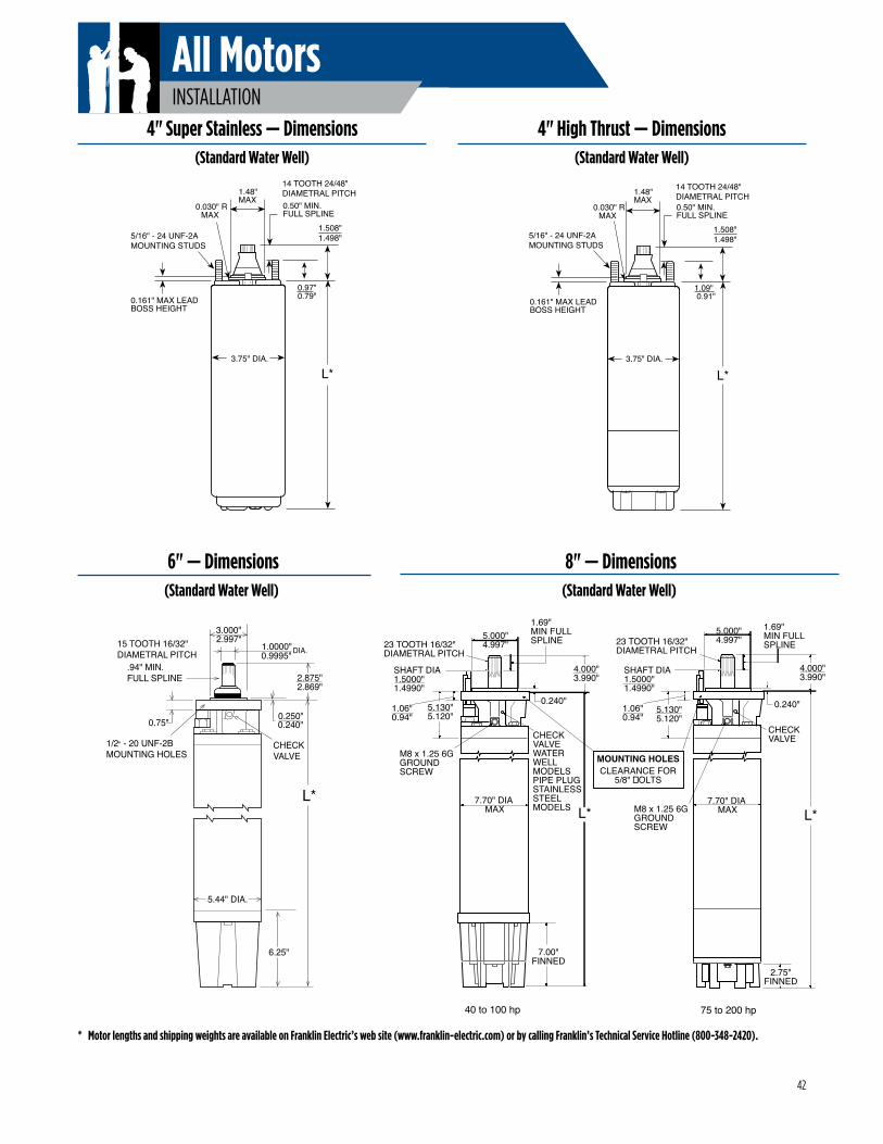
All MotorsINSTALLATION
4" Super Stainless — Dimensions(Standard Water Well)
1.508"1.498"
1.48"MAX
0.030" RMAX
0.97"0.79"
L*
0.161" MAX LEADBOSS HEIGHT
3.75" DIA.
0.50" MIN.FULL SPLINE
5/16" - 24 UNF-2AMOUNTING STUDS
14 TOOTH 24/48"DIAMETRAL PITCH
4" High Thrust — Dimensions(Standard Water Well)
L*
5.44" DIA.
0.250"0.240"
3.000"2.997"
1.0000"0.9995" DIA.
.94" MIN. FULL SPLINE 2.875"
2.869"
6.25"
CHECKVALVE
15 TOOTH 16/32"DIAMETRAL PITCH
1/2" - 20 UNF-2BMOUNTING HOLES
0.75"
6" — Dimensions(Standard Water Well)
8" — Dimensions(Standard Water Well)
* Motor lengths and shipping weights are available on Franklin Electric’s web site (www.franklin-electric.com) or by calling Franklin’s Technical Service Hotline (800-348-2420).
1.508"1.498"
1.48"MAX
0.030" RMAX
L*
0.161" MAX LEADBOSS HEIGHT
3.75" DIA.
0.50" MIN.FULL SPLINE
1.09" 0.91"
5/16" - 24 UNF-2AMOUNTING STUDS
14 TOOTH 24/48"DIAMETRAL PITCH
40 to 100 hp
5.000"4.997"
5.130"5.120"
1.69"MIN FULLSPLINE
0.240"
23 TOOTH 16/32"DIAMETRAL PITCH
SHAFT DIA1.5000"1.4990"
CHECK VALVE WATERWELL MODELSPIPE PLUG STAINLESSSTEEL MODELS
M8 x 1.25 6GGROUNDSCREW
7.70" DIA MAX
7.00"FINNED
4.000"3.990"
L*
23 TOOTH 16/32"DIAMETRAL PITCH
SHAFT DIA1.5000"1.4990"
5.130"5.120"
M8 x 1.25 6GGROUNDSCREW
2.75"FINNED
4.000"3.990"
L*
75 to 200 hp
5.000"4.997"
1.69"MIN FULLSPLINE
0.240"
CHECK VALVE
7.70" DIA MAX
MOUNTING HOLESCLEARANCE FOR
5/8" �OLTS
1.06"0.94"
1.06"0.94"
42
All MotorsINSTALLATION
4" Motors with Jam Nut: 15 to 20 ft-lb (20 to 27 Nm)
4" Motors with 2 Screw Clamp Plate: 35 to 45 in-lb (40 to 51 Nm)
6" Motors: 40 to 50 ft-lb (54 to 68 Nm)
8" Motors with 1-3/16" to 1-5/8" Jam Nut: 50 to 60 ft-lb (68 to 81 Nm)
8" Motors with 4 Screw Clamp Plate: Apply increasing torque to the screws equally in a criss-cross pattern until 80 to
90 in-lb (9.0 to 10.2 Nm) is reached.
Jam nut tightening torques recommended for field assembly are shown. Rubber compression set within the first few hours after assembly may reduce the jam nut torque. This is a normal condition which does not indicate reduced seal effectiveness. Retightening is not required, but is permissible and recommended if original torque was questionable.
A motor lead assembly should not be reused. A new lead assembly should be used whenever one is removed from the motor, because rubber set and possible damage from removal may prevent proper resealing of the old lead.
All motors returned for warranty consideration must have the lead returned with the motor.
Assemble coupling with non-toxic FDA approved waterproof grease such as Mobile FM222, Texaco CYGNUS2661, or approved equivalent. This prevents abrasives from entering the spline area and prolongs spline life.
A common question is why motor leads are smaller than specified in Franklin’s cable charts.
The leads are considered a part of the motor and actually are a connection between the large supply wire and the motor winding. The motor leads are short and there is virtually no voltage drop across the lead.
In addition, the lead assemblies operate under water, while at least part of the supply cable must operate in air. Lead assemblies running under water operate cooler.
CAUTION: Lead assemblies on submersible motors are suitable only for use in water and may overheat and cause failure if operated in air.
Shaft Height and Free End Play
Tightening Motor Lead Connector Jam Nut
Table 43
Pump to Motor Coupling
Submersible Leads and Cables
MOTORNORMAL
SHAFT HEIGHTDIMENSION
SHAFT HEIGHTFREE END PLAY
MIN. MAX.
4" 1 1/2" 38.1 mm1.508" 1.498"
38.3038.05
0.010"0.25 mm
0.045"1.14 mm
6" 2 7/8" 73.0 mm2.875"2.869"
73.0272.88
0.030"0.76 mm
0.050"1.27 mm
8" TYPE 1 4" 101.6 mm4.000"3.990"
101.60101.35
0.008"0.20 mm
0.032"0.81 mm
8" TYPE 2.1 4" 101.6 mm4.000"3.990"
101.60101.35
0.030"0.76 mm
0.080"2.03 mm
mm
mm
mm
mm
After assembling the motor to the pump, torque mounting fasteners to the following:
4" Pump and Motor: 10 lb-ft (14 Nm)
6" Pump and Motor: 50 lb-ft (68 Nm)
8" Pump and Motor: 120 lb-ft (163 Nm)
Pump to Motor Assembly
If the height, measured from the pump-mounting surface of the motor, is low and/or end play exceeds the limit, the motor thrust bearing is possibly damaged, and should be replaced.
43
All MotorsMAINTENANCE
System Troubleshooting
POSSIBLE CAUSE CHECKING PROCEDURES CORRECTIVE ACTION
A. No power or incorrect voltageCheck voltage at line terminals.The voltage must be ± 10% of rated voltage.
Contact power company if voltage is incorrect.
B. Fuses blown or circuit breakers trippedCheck fuses for recommended size and check for loose, dirty or corrodedconnections in fuse receptacle. Check for tripped circuit breakers.
Replace with proper fuse or reset circuit breakers.
C. Defective pressure switchCheck voltage at contact points. Improper contact of switch points can cause voltage less than line voltage.
Replace pressure switch or clean points.
D. Control box malfunction For detailed procedure, see pages 48-57. Repair or replace.
E. Defective wiring Check for loose or corroded connections or defective wiring. Correct faulty wiring or connections.
F. Bound pumpCheck for misalignment between pump and motor or a sand bound pump. Amp readings will be 3 to 6 times higher than normal until the overload trips.
Pull pump and correct problem. Run new installation until the water clears.
G. Defective cable or motor For detailed procedure, see pages 46 & 47. Repair or replace.
A. Pressure switch Check setting on pressure switch and examine for defects. Reset limit or replace switch.
B. Check valve - stuck open Damaged or defective check valve will not hold pressure. Replace if defective.
C. Waterlogged tank Check air charge. Clean or replace.
D. Leak in system Check system for leaks. Replace damaged pipes or repair leaks.
Motor Does Not Start
Motor Starts Too Often
44
All MotorsMAINTENANCE
System Troubleshooting
POSSIBLE CAUSE CHECKING PROCEDURES CORRECTIVE ACTION
A. Pressure switchCheck switch for welded contacts.Check switch adjustments.
Clean contacts, replace switch, or adjust setting.
B. Low water level in wellPump may exceed well capacity. Shut off pump, wait for well to recover. Check static and drawdown level from well head.
Throttle pump output or reset pump to lower level. Do not lower if sand may clog pump.
C. Leak in system Check system for leaks. Replace damaged pipes or repair leaks.
D. Worn pumpSymptoms of worn pump are similar to those of drop pipe leak or low water level in well. Reduce pressure switch setting, if pump shuts off worn parts may be the fault.
Pull pump and replace worn parts.
E. Loose coupling or broken motor shaft Check for loose coupling or damaged shaft. Replace worn or damaged parts.
F. Pump screen blocked Check for clogged intake screen. Clean screen and reset pump depth.
G. Check valve stuck closed Check operation of check valve. Replace if defective.
H. Control box malfunction See pages 48-57 for single-phase. Repair or replace.
A. Incorrect voltageUsing voltmeter, check the line terminals. Voltage must be within ± 10% of rated voltage.
Contact power company if voltage is incorrect.
B. Overheated protectorsDirect sunlight or other heat source can raise control box temperature causing protectors to trip. The box must not be hot to touch.
Shade box, provide ventilation or move box away from source.
C. Defective control box For detailed procedures, see pages 48-57. Repair or replace.
D. Defective motor or cable For detailed procedures, see pages 45 & 46. Repair or replace.
E. Worn pump or motor Check running current, see tables 13, 22, 24, 25, & 27. Replace pump and/or motor.
Motor Runs Continuously
Motor Runs But Overload Protector Trips
45
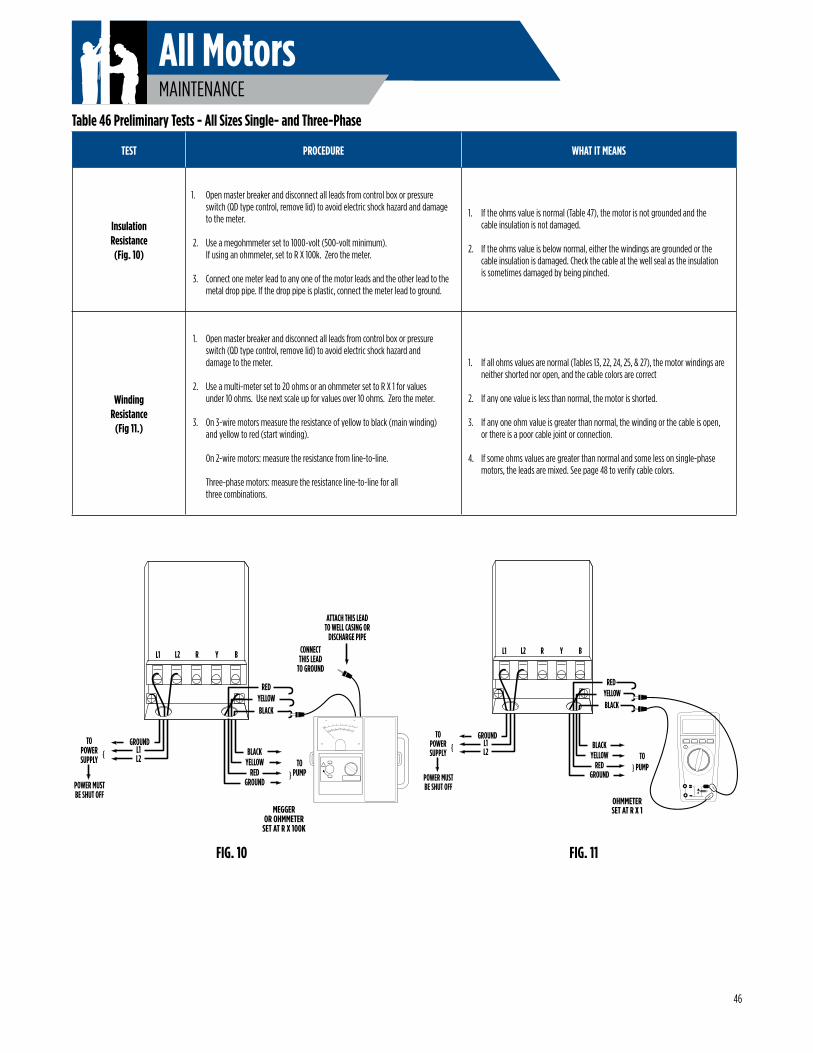
All MotorsMAINTENANCE
GROUND
L2{TO
POWERSUPPLY
BLACK
{YELLOW
REDGROUNDPOWER MUST
BE SHUT OFF
BLACKYELLOW
RED
L1 L2 R Y B
L1TO
PUMP
OHMMETERSET AT R X 1
FIG. 10 FIG. 11
Table 46 Preliminary Tests - All Sizes Single- and Three-Phase
TEST PROCEDURE WHAT IT MEANS
Insulation Resistance(Fig. 10)
1. Open master breaker and disconnect all leads from control box or pressure switch (QD type control, remove lid) to avoid electric shock hazard and damage to the meter.
2. Use a megohmmeter set to 1000-volt (500-volt minimum). If using an ohmmeter, set to R X 100k. Zero the meter.
3. Connect one meter lead to any one of the motor leads and the other lead to the metal drop pipe. If the drop pipe is plastic, connect the meter lead to ground.
1. If the ohms value is normal (Table 47), the motor is not grounded and the cable insulation is not damaged.
2. If the ohms value is below normal, either the windings are grounded or the cable insulation is damaged. Check the cable at the well seal as the insulation is sometimes damaged by being pinched.
Winding Resistance
(Fig 11.)
1. Open master breaker and disconnect all leads from control box or pressure switch (QD type control, remove lid) to avoid electric shock hazard and damage to the meter.
2. Use a multi-meter set to 20 ohms or an ohmmeter set to R X 1 for values under 10 ohms. Use next scale up for values over 10 ohms. Zero the meter.
3. On 3-wire motors measure the resistance of yellow to black (main winding) and yellow to red (start winding).
On 2-wire motors: measure the resistance from line-to-line.
Three-phase motors: measure the resistance line-to-line for all three combinations.
1. If all ohms values are normal (Tables 13, 22, 24, 25, & 27), the motor windings are neither shorted nor open, and the cable colors are correct
2. If any one value is less than normal, the motor is shorted.
3. If any one ohm value is greater than normal, the winding or the cable is open, or there is a poor cable joint or connection.
4. If some ohms values are greater than normal and some less on single-phase motors, the leads are mixed. See page 48 to verify cable colors.
46
GROUND
L2{TO
POWERSUPPLY
BLACK
{YELLOW
REDGROUNDPOWER MUST
BE SHUT OFF
BLACKYELLOW
RED
L1 L2 R Y B
L1TO
PUMP
MEGGEROR OHMMETER
SET AT R X 100K
CONNECTTHIS LEAD
TO GROUND
ATTACH THIS LEADTO WELL CASING OR
DISCHARGE PIPE
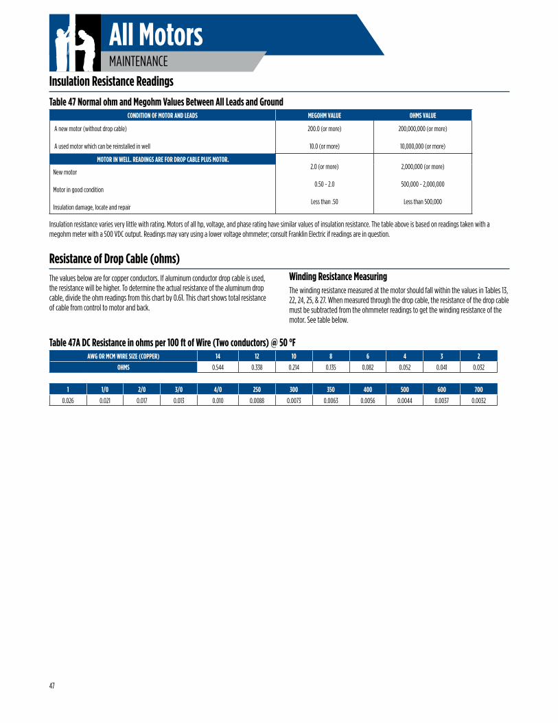
All MotorsMAINTENANCE
Insulation Resistance Readings
The values below are for copper conductors. If aluminum conductor drop cable is used, the resistance will be higher. To determine the actual resistance of the aluminum drop cable, divide the ohm readings from this chart by 0.61. This chart shows total resistance of cable from control to motor and back.
Winding Resistance MeasuringThe winding resistance measured at the motor should fall within the values in Tables 13, 22, 24, 25, & 27. When measured through the drop cable, the resistance of the drop cable must be subtracted from the ohmmeter readings to get the winding resistance of the motor. See table below.
Insulation resistance varies very little with rating. Motors of all hp, voltage, and phase rating have similar values of insulation resistance. The table above is based on readings taken with a megohm meter with a 500 VDC output. Readings may vary using a lower voltage ohmmeter; consult Franklin Electric if readings are in question.
Table 47 Normal ohm and Megohm Values Between All Leads and Ground
Table 47A DC Resistance in ohms per 100 ft of Wire (Two conductors) @ 50 °F
CONDITION OF MOTOR AND LEADS MEGOHM VALUE OHMS VALUE
A new motor (without drop cable)
A used motor which can be reinstalled in well
200.0 (or more)
10.0 (or more)
200,000,000 (or more)
10,000,000 (or more)
MOTOR IN WELL. READINGS ARE FOR DROP CABLE PLUS MOTOR.2.0 (or more)
0.50 - 2.0
Less than .50
2,000,000 (or more)
500,000 - 2,000,000
Less than 500,000
New motor Motor in good condition
Insulation damage, locate and repair
AWG OR MCM WIRE SIZE (COPPER) 14 12 10 8 6 4 3 2
OHMS 0.544 0.338 0.214 0.135 0.082 0.052 0.041 0.032
1 1/0 2/0 3/0 4/0 250 300 350 400 500 600 700
0.026 0.021 0.017 0.013 0.010 0.0088 0.0073 0.0063 0.0056 0.0044 0.0037 0.0032
Resistance of Drop Cable (ohms)
47
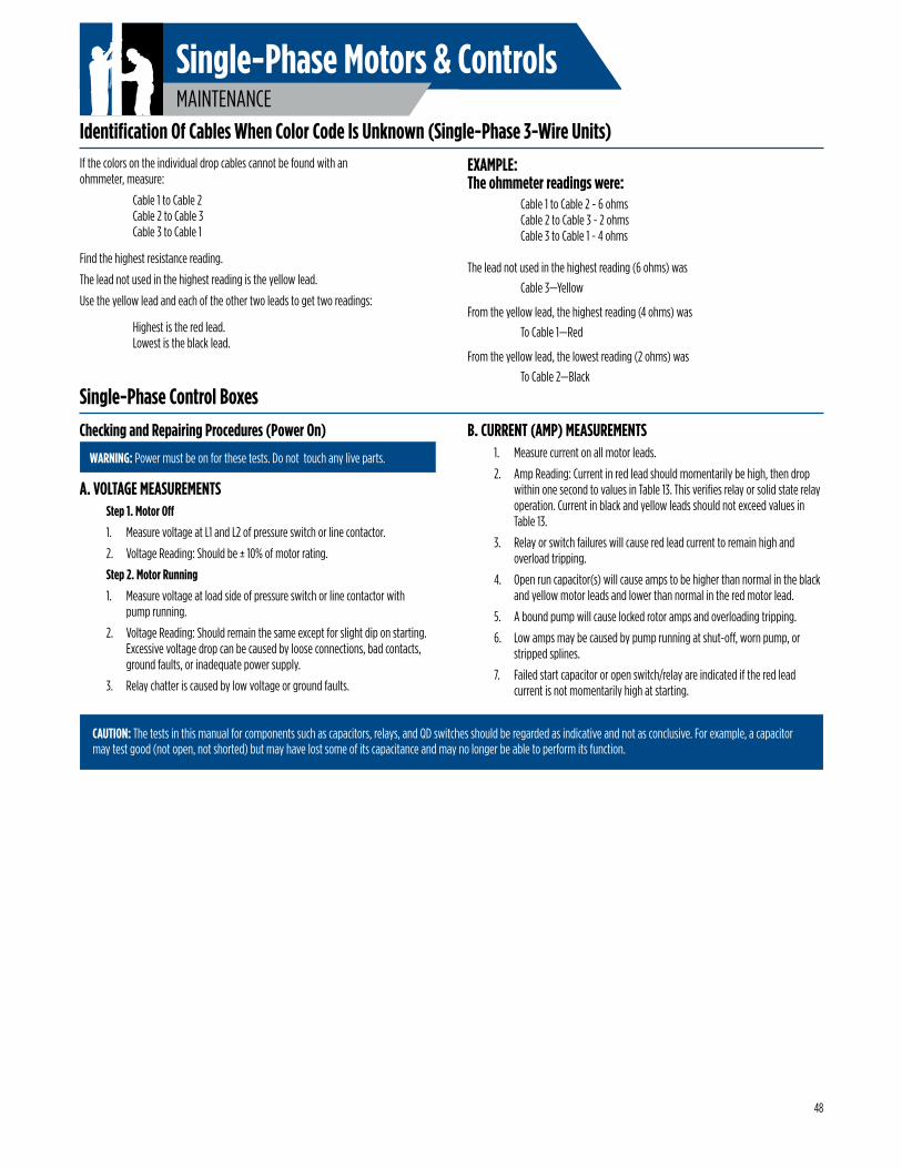
MAINTENANCE
Single-Phase Motors & Controls
WARNING: Power must be on for these tests. Do not touch any live parts.
A. VOLTAGE MEASUREMENTSStep 1. Motor Off
1. Measure voltage at L1 and L2 of pressure switch or line contactor.
2. Voltage Reading: Should be ± 10% of motor rating.
Step 2. Motor Running
1. Measure voltage at load side of pressure switch or line contactor with pump running.
2. Voltage Reading: Should remain the same except for slight dip on starting. Excessive voltage drop can be caused by loose connections, bad contacts, ground faults, or inadequate power supply.
3. Relay chatter is caused by low voltage or ground faults.
If the colors on the individual drop cables cannot be found with an ohmmeter, measure:
Cable 1 to Cable 2 Cable 2 to Cable 3 Cable 3 to Cable 1
Find the highest resistance reading.
The lead not used in the highest reading is the yellow lead.
Use the yellow lead and each of the other two leads to get two readings:
Highest is the red lead. Lowest is the black lead.
Identification Of Cables When Color Code Is Unknown (Single-Phase 3-Wire Units)EXAMPLE:The ohmmeter readings were: Cable 1 to Cable 2 - 6 ohms Cable 2 to Cable 3 - 2 ohms Cable 3 to Cable 1 - 4 ohms
The lead not used in the highest reading (6 ohms) was
Cable 3—Yellow
From the yellow lead, the highest reading (4 ohms) was
To Cable 1—Red
From the yellow lead, the lowest reading (2 ohms) was
To Cable 2—Black
Single-Phase Control BoxesB. CURRENT (AMP) MEASUREMENTS
1. Measure current on all motor leads.
2. Amp Reading: Current in red lead should momentarily be high, then drop within one second to values in Table 13. This verifies relay or solid state relay operation. Current in black and yellow leads should not exceed values in Table 13.
3. Relay or switch failures will cause red lead current to remain high and overload tripping.
4. Open run capacitor(s) will cause amps to be higher than normal in the black and yellow motor leads and lower than normal in the red motor lead.
5. A bound pump will cause locked rotor amps and overloading tripping.
6. Low amps may be caused by pump running at shut-off, worn pump, or stripped splines.
7. Failed start capacitor or open switch/relay are indicated if the red lead current is not momentarily high at starting.
CAUTION: The tests in this manual for components such as capacitors, relays, and QD switches should be regarded as indicative and not as conclusive. For example, a capacitor may test good (not open, not shorted) but may have lost some of its capacitance and may no longer be able to perform its function.
Checking and Repairing Procedures (Power On)
48
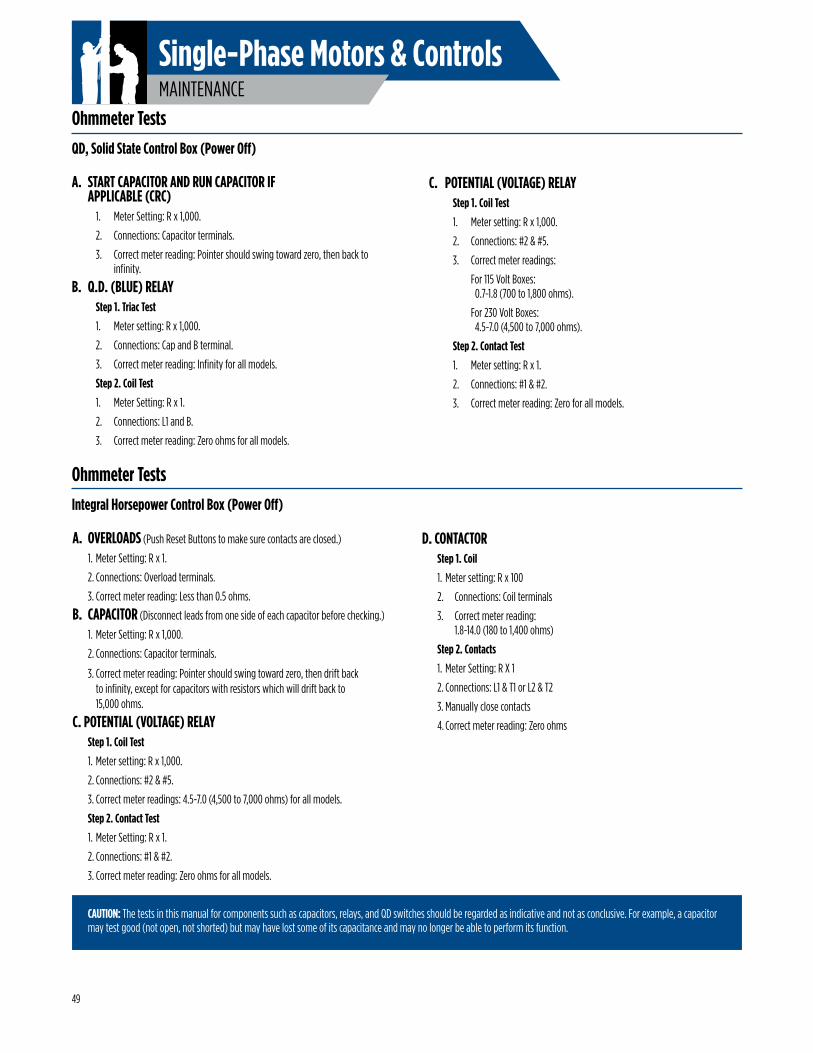
MAINTENANCE
Single-Phase Motors & Controls
Integral Horsepower Control Box (Power Off)
A. OVERLOADS (Push Reset Buttons to make sure contacts are closed.)
1. Meter Setting: R x 1.
2. Connections: Overload terminals.
3. Correct meter reading: Less than 0.5 ohms.
B. CAPACITOR (Disconnect leads from one side of each capacitor before checking.)
1. Meter Setting: R x 1,000.
2. Connections: Capacitor terminals.
3. Correct meter reading: Pointer should swing toward zero, then drift back to infinity, except for capacitors with resistors which will drift back to 15,000 ohms.
C. POTENTIAL (VOLTAGE) RELAY Step 1. Coil Test
1. Meter setting: R x 1,000.
2. Connections: #2 & #5.
3. Correct meter readings: 4.5-7.0 (4,500 to 7,000 ohms) for all models.
Step 2. Contact Test
1. Meter Setting: R x 1.
2. Connections: #1 & #2.
3. Correct meter reading: Zero ohms for all models.
QD, Solid State Control Box (Power Off)
A. START CAPACITOR AND RUN CAPACITOR IF APPLICABLE (CRC)
1. Meter Setting: R x 1,000.
2. Connections: Capacitor terminals.
3. Correct meter reading: Pointer should swing toward zero, then back to infinity.
B. Q.D. (BLUE) RELAY Step 1. Triac Test
1. Meter setting: R x 1,000.
2. Connections: Cap and B terminal.
3. Correct meter reading: Infinity for all models.
Step 2. Coil Test
1. Meter Setting: R x 1.
2. Connections: L1 and B.
3. Correct meter reading: Zero ohms for all models.
CAUTION: The tests in this manual for components such as capacitors, relays, and QD switches should be regarded as indicative and not as conclusive. For example, a capacitor may test good (not open, not shorted) but may have lost some of its capacitance and may no longer be able to perform its function.
C. POTENTIAL (VOLTAGE) RELAYStep 1. Coil Test
1. Meter setting: R x 1,000.
2. Connections: #2 & #5.
3. Correct meter readings:
For 115 Volt Boxes: 0.7-1.8 (700 to 1,800 ohms).
For 230 Volt Boxes: 4.5-7.0 (4,500 to 7,000 ohms).
Step 2. Contact Test
1. Meter setting: R x 1.
2. Connections: #1 & #2.
3. Correct meter reading: Zero for all models.
D. CONTACTOR Step 1. Coil
1. Meter setting: R x 100
2. Connections: Coil terminals
3. Correct meter reading: 1.8-14.0 (180 to 1,400 ohms)
Step 2. Contacts
1. Meter Setting: R X 1
2. Connections: L1 & T1 or L2 & T2
3. Manually close contacts
4. Correct meter reading: Zero ohms
Ohmmeter Tests
Ohmmeter Tests
49
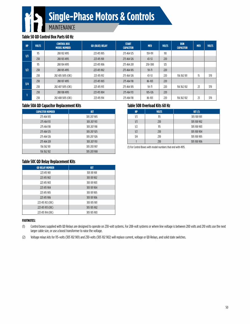
MAINTENANCE
Single-Phase Motors & Controls
FOOTNOTES:
(1) Control boxes supplied with QD Relays are designed to operate on 230-volt systems. For 208-volt systems or where line voltage is between 200 volts and 210 volts use the next larger cable size, or use a boost transformer to raise the voltage.
(2) Voltage relays kits for 115-volts (305 102 901) and 230-volts (305 102 902) will replace current, voltage or QD Relays, and solid state switches.
(1) For Control Boxes with model numbers that end with 4915.
Table 50 QD Control Box Parts 60 Hz
Table 50A QD Capacitor Replacement Kits
Table 50C QD Relay Replacement Kits
Table 50B Overload Kits 60 Hz
HP VOLTSCONTROL BOX
MODEL NUMBER QD (BLUE) RELAY
START CAPACITOR
MFD VOLTSRUN
CAPACITORMFD VOLTS
1/3115 280 102 4915 223 415 905 275 464 125 159-191 110
230 280 103 4915 223 415 901 275 464 126 43-53 220
1/2
115 280 104 4915 223 415 906 275 464 201 250-300 125
230 280 105 4915 223 415 902 275 464 105 59-71 220
230 282 405 5015 (CRC) 223 415 912 275 464 126 43-53 220 156 362 101 15 370
3/4230 280 107 4915 223 415 903 275 464 118 86-103 220
230 282 407 5015 (CRC) 223 415 913 275 464 105 59-71 220 156 362 102 23 370
1230 280 108 4915 223 415 904 275 464 113 105-126 220
230 282 408 5015 (CRC) 223 415 914 275 464 118 86-103 220 156 362 102 23 370
CAPACITOR NUMBER KIT
275 464 105 305 207 905
275 464 113 305 207 913
275 464 118 305 207 918
275 464 125 305 207 925
275 464 126 305 207 926
275 464 201 305 207 951
156 362 101 305 203 907
156 362 102 305 203 908
QD RELAY NUMBER KIT
223 415 901 305 101 901
223 415 902 305 101 902
223 415 903 305 101 903
223 415 904 305 101 904
223 415 905 305 101 905
223 415 906 305 101 906
223 415 912 (CRC) 305 105 901
223 415 913 (CRC) 305 105 902
223 415 914 (CRC) 305 105 903
HP VOLTS KIT (1)
1/3 115 305 100 901
1/3 230 305 100 902
1/2 115 305 100 903
1/2 230 305 100 904
3/4 230 305 100 905
1 230 305 100 906
50
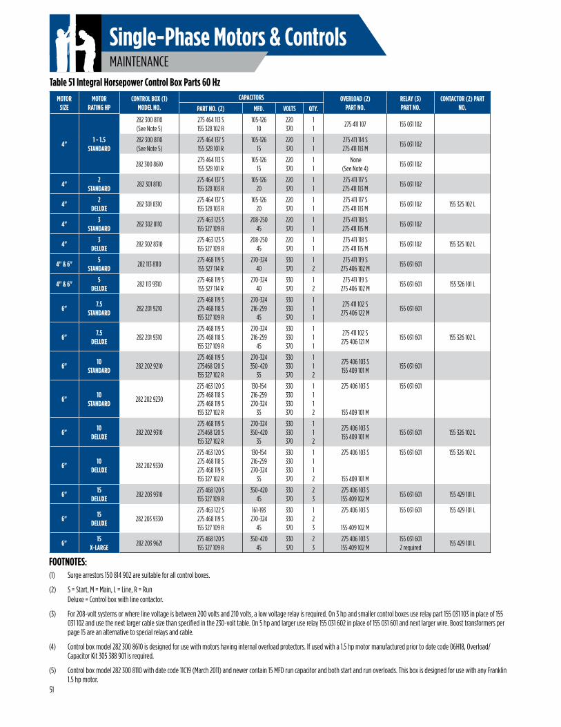
MAINTENANCE
Single-Phase Motors & Controls
FOOTNOTES:(1) Surge arrestors 150 814 902 are suitable for all control boxes.
(2) S = Start, M = Main, L = Line, R = Run Deluxe = Control box with line contactor.
(3) For 208-volt systems or where line voltage is between 200 volts and 210 volts, a low voltage relay is required. On 3 hp and smaller control boxes use relay part 155 031 103 in place of 155 031 102 and use the next larger cable size than specified in the 230-volt table. On 5 hp and larger use relay 155 031 602 in place of 155 031 601 and next larger wire. Boost transformers per page 15 are an alternative to special relays and cable.
(4) Control box model 282 300 8610 is designed for use with motors having internal overload protectors. If used with a 1.5 hp motor manufactured prior to date code 06H18, Overload/Capacitor Kit 305 388 901 is required.
(5) Control box model 282 300 8110 with date code 11C19 (March 2011) and newer contain 15 MFD run capacitor and both start and run overloads. This box is designed for use with any Franklin 1.5 hp motor.
Table 51 Integral Horsepower Control Box Parts 60 HzMOTOR
SIZEMOTOR
RATING HPCONTROL BOX (1)
MODEL NO.CAPACITORS OVERLOAD (2)
PART NO.RELAY (3) PART NO.
CONTACTOR (2) PART NO.PART NO. (2) MFD. VOLTS QTY.
4"1 - 1.5
STANDARD
282 300 8110(See Note 5)
275 464 113 S155 328 102 R
105-12610
220370
11
275 411 107 155 031 102
282 300 8110(See Note 5)
275 464 137 S155 328 101 R
105-12615
220370
11
275 411 114 S275 411 113 M
155 031 102
282 300 8610275 464 113 S155 328 101 R
105-12615
220370
11
None (See Note 4)
155 031 102
4"2
STANDARD282 301 8110
275 464 137 S155 328 103 R
105-12620
220370
11
275 411 117 S275 411 113 M
155 031 102
4"2
DELUXE282 301 8310
275 464 137 S155 328 103 R
105-12620
220370
11
275 411 117 S275 411 113 M
155 031 102 155 325 102 L
4"3
STANDARD282 302 8110
275 463 123 S155 327 109 R
208-25045
220370
11
275 411 118 S275 411 115 M
155 031 102
4"3
DELUXE282 302 8310
275 463 123 S155 327 109 R
208-25045
220370
11
275 411 118 S275 411 115 M
155 031 102 155 325 102 L
4" & 6"5
STANDARD282 113 8110
275 468 119 S155 327 114 R
270-32440
330370
12
275 411 119 S275 406 102 M
155 031 601
4" & 6"5
DELUXE282 113 9310
275 468 119 S155 327 114 R
270-32440
330370
12
275 411 119 S275 406 102 M
155 031 601 155 326 101 L
6"7.5
STANDARD282 201 9210
275 468 119 S275 468 118 S155 327 109 R
270-324216-259
45
330330370
111
275 411 102 S275 406 122 M
155 031 601
6"7.5
DELUXE282 201 9310
275 468 119 S275 468 118 S155 327 109 R
270-324216-259
45
330330370
111
275 411 102 S275 406 121 M
155 031 601 155 326 102 L
6"10
STANDARD282 202 9210
275 468 119 S275468 120 S155 327 102 R
270-324350-420
35
330330370
112
275 406 103 S155 409 101 M
155 031 601
6"10
STANDARD282 202 9230
275 463 120 S275 468 118 S275 468 119 S155 327 102 R
130-154216-259270-324
35
330330330370
1112
275 406 103 S
155 409 101 M
155 031 601
6"10
DELUXE282 202 9310
275 468 119 S275468 120 S155 327 102 R
270-324350-420
35
330330370
112
275 406 103 S155 409 101 M
155 031 601 155 326 102 L
6"10
DELUXE282 202 9330
275 463 120 S275 468 118 S275 468 119 S155 327 102 R
130-154216-259270-324
35
330330330370
1112
275 406 103 S
155 409 101 M
155 031 601 155 326 102 L
6"15
DELUXE282 203 9310
275 468 120 S155 327 109 R
350-42045
330370
23
275 406 103 S155 409 102 M
155 031 601 155 429 101 L
6"15
DELUXE282 203 9330
275 463 122 S275 468 119 S155 327 109 R
161-193270-324
45
330330370
123
275 406 103 S
155 409 102 M
155 031 601 155 429 101 L
6"15
X-LARGE282 203 9621
275 468 120 S155 327 109 R
350-42045
330370
23
275 406 103 S155 409 102 M
155 031 6012 required
155 429 101 L
51
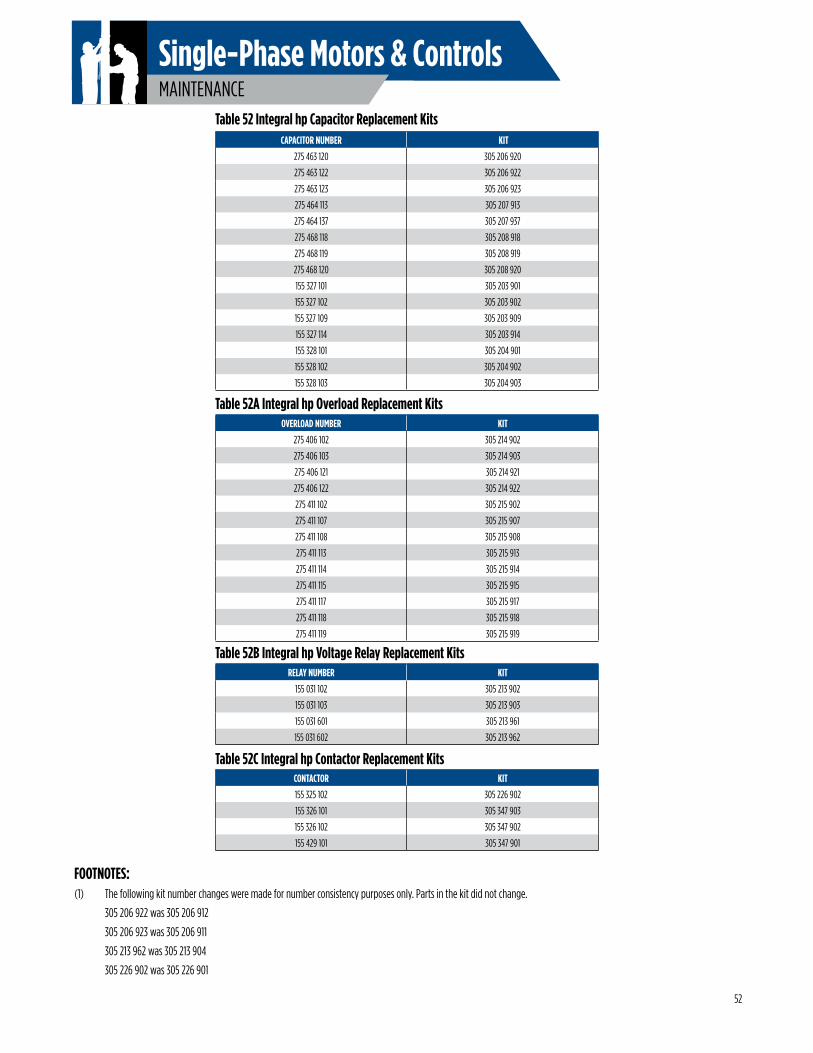
MAINTENANCE
Single-Phase Motors & Controls
CAPACITOR NUMBER KIT
275 463 120 305 206 920
275 463 122 305 206 922
275 463 123 305 206 923
275 464 113 305 207 913
275 464 137 305 207 937
275 468 118 305 208 918
275 468 119 305 208 919
275 468 120 305 208 920
155 327 101 305 203 901
155 327 102 305 203 902
155 327 109 305 203 909
155 327 114 305 203 914
155 328 101 305 204 901
155 328 102 305 204 902
155 328 103 305 204 903
OVERLOAD NUMBER KIT
275 406 102 305 214 902
275 406 103 305 214 903
275 406 121 305 214 921
275 406 122 305 214 922
275 411 102 305 215 902
275 411 107 305 215 907
275 411 108 305 215 908
275 411 113 305 215 913
275 411 114 305 215 914
275 411 115 305 215 915
275 411 117 305 215 917
275 411 118 305 215 918
275 411 119 305 215 919
RELAY NUMBER KIT
155 031 102 305 213 902
155 031 103 305 213 903
155 031 601 305 213 961
155 031 602 305 213 962
CONTACTOR KIT
155 325 102 305 226 902
155 326 101 305 347 903
155 326 102 305 347 902
155 429 101 305 347 901
Table 52 Integral hp Capacitor Replacement Kits
Table 52A Integral hp Overload Replacement Kits
Table 52B Integral hp Voltage Relay Replacement Kits
Table 52C Integral hp Contactor Replacement Kits
FOOTNOTES:(1) The following kit number changes were made for number consistency purposes only. Parts in the kit did not change.
305 206 922 was 305 206 912
305 206 923 was 305 206 911
305 213 962 was 305 213 904
305 226 902 was 305 226 901
52
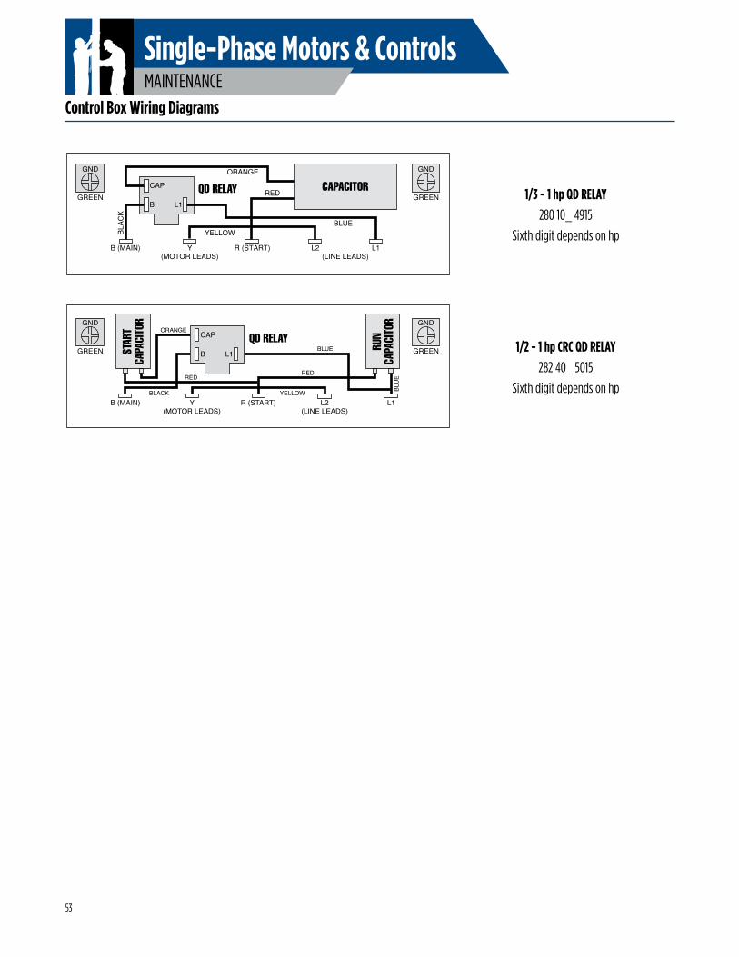
MAINTENANCE
Single-Phase Motors & Controls
1/2 - 1 hp CRC QD RELAY282 40_ 5015
Sixth digit depends on hp
Control Box Wiring Diagrams
GND
GREENCAPACITORCAP
B L1
B (MAIN) Y R (START) L2 L1(MOTOR LEADS) (LINE LEADS)
ORANGE
QD RELAY
BLA
CK
YELLOW
RED
BLUE
GND
GREEN
GND
GREEN
GND
GREEN STAR
TCA
PACI
TOR
RUN
CAPA
CITO
R
CAP
B L1
QD RELAY
B (MAIN) Y R (START) L2 L1(MOTOR LEADS) (LINE LEADS)
RED
YELLOW
BLUE
BLU
EBLACK
RED
ORANGE
1/3 - 1 hp QD RELAY280 10_ 4915
Sixth digit depends on hp
53
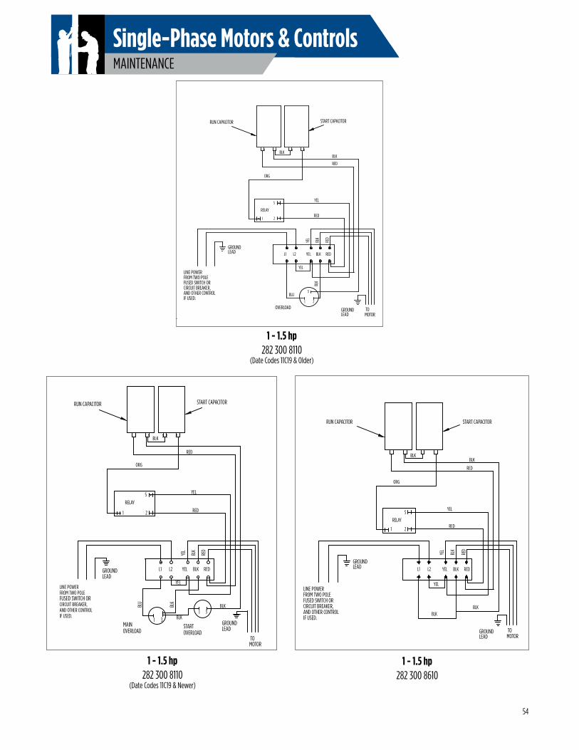
MAINTENANCE
Single-Phase Motors & Controls
1 - 1.5 hp282 300 8110
(Date Codes 11C19 & Newer)
1 - 1.5 hp282 300 8610
RELAY
L1 L2 YEL BLK RED
LINE POWERFROM TWO POLEFUSED SWITCH ORCIRCUIT BREAKER,AND OTHER CONTROLIF USED.
TOMOTOR
RED
BLK
YEL
BLKBLK
YEL
1 2
5
RED
YEL
RUN CAPACITOR START CAPACITOR
BLK
ORG
BLK
RED
GROUNDLEAD
GROUNDLEAD
LINE POWERFROM TWO POLEFUSED SWITCH ORCIRCUIT BREAKER,AND OTHER CONTROLIF USED.
OVERLOAD TOMOTOR
RED
BLK
YEL
1 2
3BLU
BLK
YEL
1 2
5
RED
YEL
START CAPACITORRUN CAPACITOR
BLK
ORG
BLK
RED
GROUNDLEAD
GROUNDLEAD
RELAY
L1 L2 YEL BLK RED
1 - 1.5 hp282 300 8110
(Date Codes 11C19 & Older)
STARTOVERLOAD
LINE POWERFROM TWO POLEFUSED SWITCH ORCIRCUIT BREAKER,AND OTHER CONTROLIF USED.
RELAY
1 2
5
TOMOTOR
BLK
RED
RED
YEL
31
MAINOVERLOAD
1 3
RED
BLK
YEL
BLU
BLK
YEL
START CAPACITORRUN CAPACITOR
BLK
BLK
ORG
GROUNDLEAD
GROUNDLEAD
L1 L2 YEL BLK RED
54
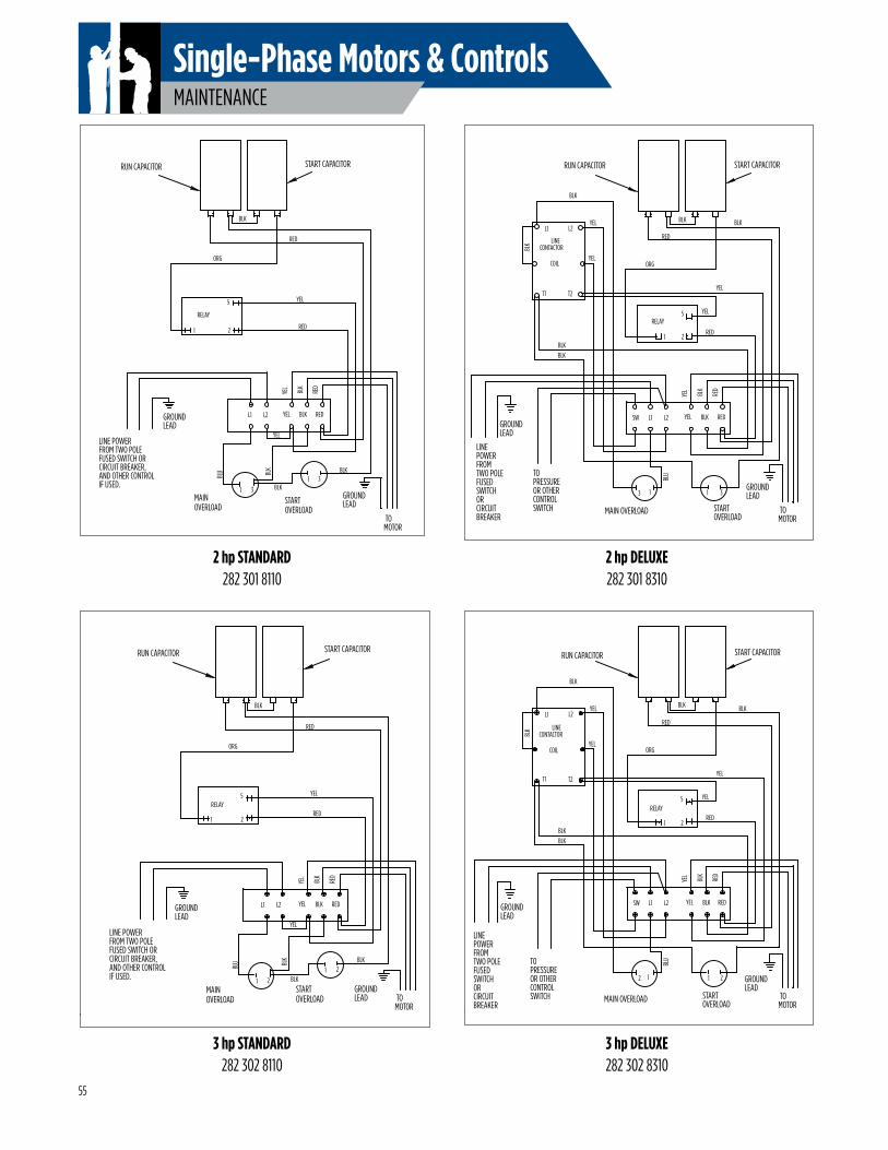
MAINTENANCE
Single-Phase Motors & Controls
STARTOVERLOAD
LINE POWERFROM TWO POLEFUSED SWITCH ORCIRCUIT BREAKER,AND OTHER CONTROLIF USED.
RELAY
1 2
5
TOMOTOR
BLK
RED
RED
YEL
31
MAINOVERLOAD
1 3
RED
BLK
YEL
BLU BL
K
YEL
START CAPACITORRUN CAPACITOR
BLK
BLK
ORG
GROUNDLEAD
GROUNDLEAD
L1 L2 YEL BLK RED
STARTOVERLOAD
LINEPOWERFROMTWO POLEFUSEDSWITCHORCIRCUITBREAKER
TOPRESSUREOR OTHERCONTROLSWITCH
RELAY
START CAPACITORRUN CAPACITOR
LINECONTACTOR
1 2
5
T2T1
L1 L2
COIL
TOMOTOR
RED
BLK
YEL
31
ORG
MAIN OVERLOAD
3 1
RED
BLK
YEL
BLU
RED
YEL
BLKBLK
BLK
BLKBLK
YEL
YEL
GROUNDLEAD
GROUNDLEAD
L1 L2 YEL BLK REDSW
STARTOVERLOAD
LINE POWERFROM TWO POLEFUSED SWITCH ORCIRCUIT BREAKER,AND OTHER CONTROLIF USED.
RELAY
1 2
5
TOMOTOR
BLK
RED
RED
YEL
21
MAINOVERLOAD
1 2
RED
BLK
YEL
BLU BL
K
YEL
START CAPACITORRUN CAPACITOR
BLK
BLK
ORG
GROUNDLEAD
GROUNDLEAD
L1 L2 YEL BLK RED
STARTOVERLOAD
LINEPOWERFROMTWO POLEFUSEDSWITCHORCIRCUITBREAKER
TOPRESSUREOR OTHERCONTROLSWITCH
RELAY
START CAPACITORRUN CAPACITOR
LINECONTACTOR
1 2
5
T2T1
L1 L2
COIL
TOMOTOR
RED
BLK
YEL
21
ORG
MAIN OVERLOAD
2 1
RED
BLK
YEL
BLU
RED
YEL
BLK
BLK
BLKBLK
YEL
YEL
GROUNDLEAD
GROUNDLEAD
L1 L2 YEL BLK REDSW
BLK
2 hp STANDARD282 301 8110
3 hp STANDARD282 302 8110
3 hp DELUXE282 302 8310
2 hp DELUXE282 301 8310
55
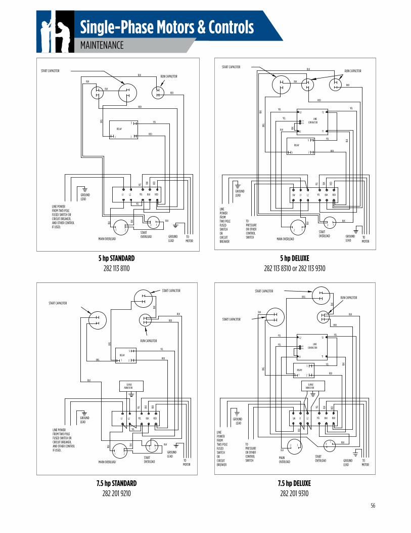
MAINTENANCE
Single-Phase Motors & Controls
STARTOVERLOAD
LINE POWERFROM TWO POLEFUSED SWITCH ORCIRCUIT BREAKER,AND OTHER CONTROLIF USED.
RELAY
START CAPACITOR
1 2
5
TOMOTOR
BLK
RED
RED
ORG
YEL
13
SURGEARRESTOR
MAIN OVERLOAD
1 2
BLK
RED
BLK
YEL
BLU BL
K
YEL
BLK
ORG
BLK
RUN CAPACITOR
START CAPACITOR
GROUNDLEAD
GROUNDLEAD
L1 L2 YEL BLK RED
STARTOVERLOAD
LINEPOWERFROMTWO POLEFUSEDSWITCHORCIRCUITBREAKER
TOPRESSUREOR OTHERCONTROLSWITCH
MAIN OVERLOAD
RELAY
START CAPACITOR
RUN CAPACITOR
1 2
5
TOMOTOR
BLK
BLK
BLK
BLU
YEL
RED
RED
ORG
YEL
REDBLKYEL
121
3
START CAPACITOR
BLK
ORG
BLK
YEL
SURGEARRESTOR
BLK
GROUNDLEAD
GROUNDLEAD
SW L1 L2 YEL BLK RED
CONTACTOR
L2
COIL
L1
COIL
T2
T1
LINE
YEL
5 hp STANDARD282 113 8110
5 hp DELUXE282 113 8310 or 282 113 9310
7.5 hp STANDARD282 201 9210
7.5 hp DELUXE282 201 9310
STARTOVERLOAD
LINEPOWERFROMTWO POLEFUSEDSWITCHORCIRCUITBREAKER
TOPRESSUREOR OTHERCONTROLSWITCH
RELAY
START CAPACITORRUN CAPACITOR
1 2
5
T2
T1L1
L2
TOMOTOR
BLK
RED
BLK
YEL
YEL
RED
RED
ORG
YEL
12
BLK
YEL
BLK
MAIN OVERLOAD
2 1
BLK
RED
BLK
YEL
BLU
BLK
GROUNDLEAD
GROUNDLEAD L1 L2 YEL BLK REDSW
COIL
COIL
BLK
LINE CONTACTOR
STARTOVERLOAD
LINE POWERFROM TWO POLEFUSED SWITCH ORCIRCUIT BREAKER,AND OTHER CONTROLIF USED.
RELAY
START CAPACITOR
RUN CAPACITOR
1 2
5
TOMOTOR
BLK
REDBLK
RED
RED
ORG
YEL
12
BLK
MAIN OVERLOAD
1 2
BLK
RED
BLK
YEL
BLU BL
K
YEL
GROUNDLEAD
GROUNDLEAD
L1 L2 YEL BLK RED
56
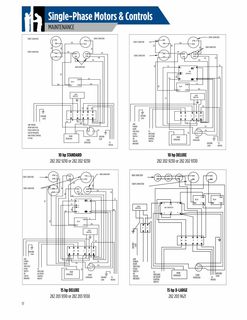
MAINTENANCE
Single-Phase Motors & Controls
BREAKERCIRCUIT
SWITCHFUSEDTWO POLEFROMPOWERLINE
OR CONTROLSWITCH
OR OTHERPRESSURETO
LEADGROUND
ORG
BLK
START CAPACITOR
START CAPACITOR
MOTOR TO
YEL
OVERLOADMAIN
BLK
BLK
OVERLOADSTART
2
1
LEADGROUND
BLK
RED
RELAY
1 2
5
YEL
BLK
YEL
ARRESTORSURGE
YEL
RED
BLK
YEL
ORG
RED
RUN CAPACITORBLK
BLK
START CAPACITOR
SW SW L1 L2 RED
CONTACTOR
L2
COIL
L1
COIL
T2
T1
LINE
BLK
RED
ORG
BLK
BLK
10 hp STANDARD282 202 9210 or 282 202 9230
10 hp DELUXE282 202 9230 or 282 202 9330
15 hp DELUXE282 203 9310 or 282 203 9330
LINE POWERFROM TWO POLEFUSED SWITCH ORCIRCUIT BREAKER,AND OTHER CONTROLIF USED.
GROUNDLEAD
START CAPACITOR
START CAPACITOR
MOTOR
MAINOVERLOAD
L1 L2
OVERLOADSTART
12
LEADGROUND
RED
YEL
YEL BLK
ORG 1 2
RELAY5
RED
ARRESTORSURGE
YEL
TO
RUN CAPACITOR
BLK
RED
BLK
START CAPACITOR
ORG
BLK
BLK
BLK
YEL
BLK
RED
BLK
REDBL
KOR
GBLK
STARTOVERLOAD
LINEPOWERFROMTWO POLEFUSEDSWITCHORCIRCUITBREAKER
TOPRESSUREOR OTHERCONTROLSWITCH
MAINOVERLOAD
RELAY
START CAPACITOR
START CAPACITOR
1 2
5
TOMOTOR
BLK
YEL
RED
RED
ORG
YEL
1
2
BLK
ORG
BLK
YEL
SURGEARRESTOR
BLK
RED
BLK
BLK
BLK
YEL
BLK
GROUNDLEAD
GROUNDLEAD
RUN CAPACITOR
SW SW L1 L2 RED
BLK
REDRED
T2T1L1
L2
BLK
COIL
COIL
YEL
BLK
BLK
15 hp X-LARGE282 203 9621
STARTOVERLOAD
LINEPOWERFROMTWO POLEFUSEDSWITCHORCIRCUITBREAKER
TOPRESSUREOR OTHERCONTROLSWITCH
MAINOVERLOAD
RELAY
START CAPACITOR
RUN CAPACITOR
LINE CONTACTOR
1 2
5
T2
T1L1
L2 COIL
TOMOTOR
1
2
COIL
SURGEARRESTOR
GROUNDLEAD
5 RELAY
21
L2 L1
GROU
NDLE
AD
SW SW B Y R
57
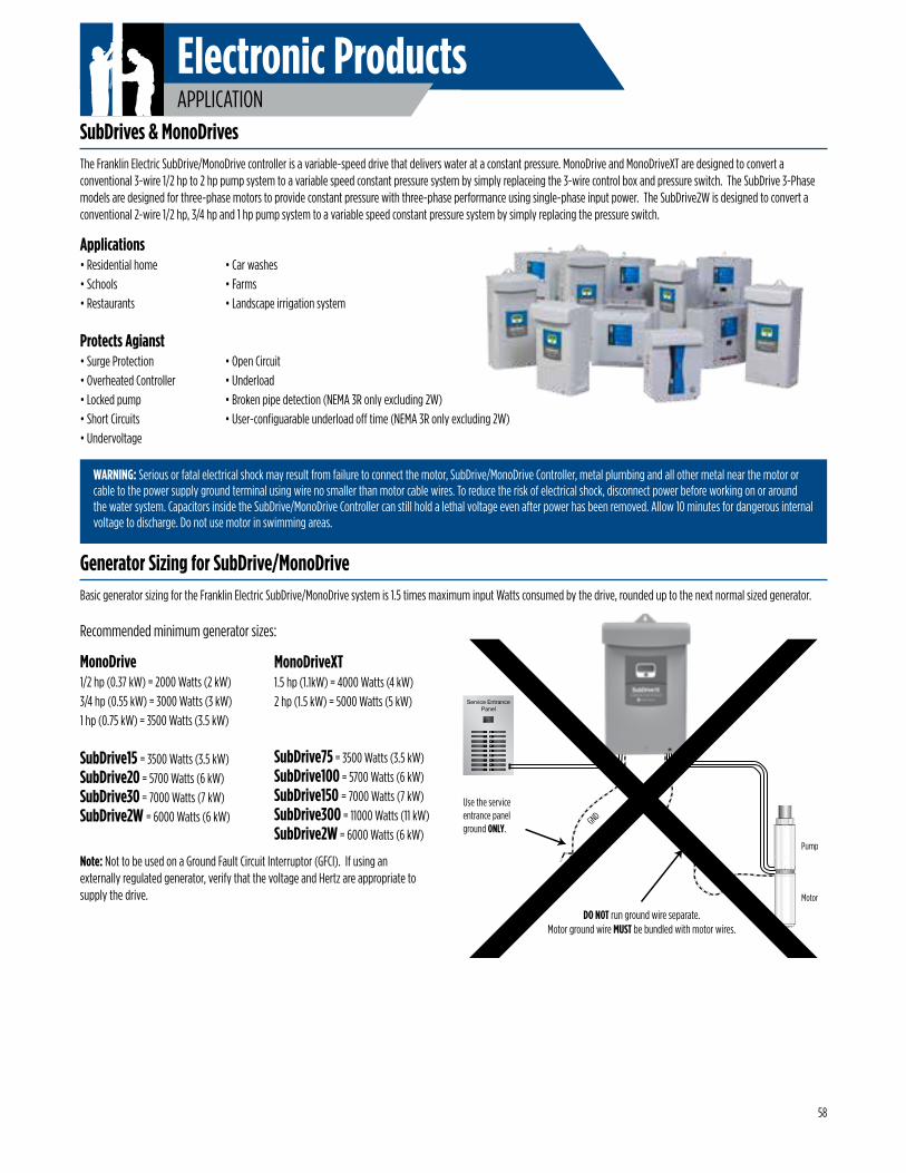
Electronic ProductsAPPLICATION
WARNING: Serious or fatal electrical shock may result from failure to connect the motor, SubDrive/MonoDrive Controller, metal plumbing and all other metal near the motor or cable to the power supply ground terminal using wire no smaller than motor cable wires. To reduce the risk of electrical shock, disconnect power before working on or around the water system. Capacitors inside the SubDrive/MonoDrive Controller can still hold a lethal voltage even after power has been removed. Allow 10 minutes for dangerous internal voltage to discharge. Do not use motor in swimming areas.
SubDrives & MonoDrivesThe Franklin Electric SubDrive/MonoDrive controller is a variable-speed drive that delivers water at a constant pressure. MonoDrive and MonoDriveXT are designed to convert a conventional 3-wire 1/2 hp to 2 hp pump system to a variable speed constant pressure system by simply replaceing the 3-wire control box and pressure switch. The SubDrive 3-Phase models are designed for three-phase motors to provide constant pressure with three-phase performance using single-phase input power. The SubDrive2W is designed to convert a conventional 2-wire 1/2 hp, 3/4 hp and 1 hp pump system to a variable speed constant pressure system by simply replacing the pressure switch.
Applications• Residential home • Car washes• Schools • Farms• Restaurants • Landscape irrigation system
Protects Agianst• Surge Protection • Overheated Controller• Locked pump• Short Circuits• Undervoltage
58
• Open Circuit• Underload• Broken pipe detection (NEMA 3R only excluding 2W)• User-configuarable underload off time (NEMA 3R only excluding 2W)
Generator Sizing for SubDrive/MonoDriveBasic generator sizing for the Franklin Electric SubDrive/MonoDrive system is 1.5 times maximum input Watts consumed by the drive, rounded up to the next normal sized generator.
Recommended minimum generator sizes:
MonoDrive1/2 hp (0.37 kW) = 2000 Watts (2 kW)3/4 hp (0.55 kW) = 3000 Watts (3 kW)1 hp (0.75 kW) = 3500 Watts (3.5 kW)
SubDrive15 = 3500 Watts (3.5 kW)SubDrive20 = 5700 Watts (6 kW)SubDrive30 = 7000 Watts (7 kW)SubDrive2W = 6000 Watts (6 kW)
MonoDriveXT1.5 hp (1.1kW) = 4000 Watts (4 kW)2 hp (1.5 kW) = 5000 Watts (5 kW)
SubDrive75 = 3500 Watts (3.5 kW)SubDrive100 = 5700 Watts (6 kW)SubDrive150 = 7000 Watts (7 kW)SubDrive300 = 11000 Watts (11 kW)SubDrive2W = 6000 Watts (6 kW)
Note: Not to be used on a Ground Fault Circuit Interruptor (GFCI). If using an externally regulated generator, verify that the voltage and Hertz are appropriate to supply the drive.
Service EntrancePanel
GNDUse the service entrance panelground ONLY.
DO NOT run ground wire separate.Motor ground wire MUST be bundled with motor wires.
Pump
Motor
GND
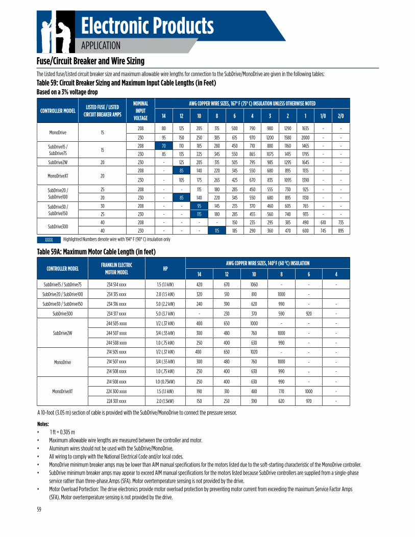
Electronic ProductsAPPLICATION
Fuse/Circuit Breaker and Wire Sizing
CONTROLLER MODELLISTED FUSE / LISTED
CIRCUIT BREAKER AMPS
NOMINAL INPUT
VOLTAGE
AWG COPPER WIRE SIZES, 167° F (75° C) INSULATION UNLESS OTHERWISE NOTED
14 12 10 8 6 4 3 2 1 1/0 2/0
MonoDrive 15208 80 125 205 315 500 790 980 1290 1635 - -
230 95 150 250 385 615 970 1200 1580 2000 - -
SubDrive15 / SubDrive75
15208 70 110 185 280 450 710 880 1160 1465 - -
230 85 135 225 345 550 865 1075 1415 1795 - -
SubDrive2W 20 230 - 125 205 315 505 795 985 1295 1645 - -
MonoDriveXT 20208 - 85 140 220 345 550 680 895 1135 - -
230 - 105 175 265 425 670 835 1095 1390 - -
SubDrive20 / SubDrive100
25 208 - - 115 180 285 450 555 730 925 - -
20 230 - 85 140 220 345 550 680 895 1130 - -
SubDrive30 / SubDrive150
30 208 - - 95 145 235 370 460 605 765 - -
25 230 - - 115 180 285 455 560 740 935 - -
SubDrive30040 208 - - - - 150 235 295 385 490 610 735
40 230 - - - 115 185 290 360 470 600 745 895
Table 59A: Maximum Motor Cable Length (in feet)
CONTROLLER MODELFRANKLIN ELECTRIC
MOTOR MODELHP
AWG COPPER WIRE SIZES, 140O F (60 OC) INSULATION
14 12 10 8 6 4
SubDrive15 / SubDrive75 234 514 xxxx 1.5 (1.1 kW) 420 670 1060 - - -
SubDrive20 / SubDrive100 234 315 xxxx 2.0 (1.5 kW) 320 510 810 1000 -
SubDrive30 / SubDrive150 234 316 xxxx 3.0 (2.2 kW) 240 390 620 990 - -
SubDrive300 234 317 xxxx 5.0 (3.7 kW) - 230 370 590 920 -
SubDrive2W
244 505 xxxx 1/2 (.37 kW) 400 650 1000 - - -
244 507 xxxx 3/4 (.55 kW) 300 480 760 1000 - -
244 508 xxxx 1.0 (.75 kW) 250 400 630 990 - -
MonoDrive
214 505 xxxx 1/2 (.37 kW) 4 400 00 650 1020 - - -
214 507 xxxx 3/4 (.55 kW) 300 480 760 1000 - -
214 508 xxxx 1.0 (.75 kW) 250 400 630 990 - -
MonoDriveXT
214 508 xxxx 1.0 (0.75kW) 250 400 630 990 - -
224 300 xxxx 1.5 (1.1 kW) 190 310 480 770 1000 -
224 301 xxxx 2.0 (1.5kW) 150 250 390 620 970 -
Table 59: Circuit Breaker Sizing and Maximum Input Cable Lengths (in Feet)Based on a 3% voltage drop
Highlighted Numbers denote wire with 194° F (90° C) insulation onlyXXXX
A 10-foot (3.05 m) section of cable is provided with the SubDrive/MonoDrive to connect the pressure sensor.
Notes:• 1 ft = 0.305 m• Maximum allowable wire lengths are measured between the controller and motor.• Aluminum wires should not be used with the SubDrive/MonoDrive.• All wiring to comply with the National Electrical Code and/or local codes.• MonoDrive minimum breaker amps may be lower than AIM manual specifications for the motors listed due to the soft-starting characteristic of the MonoDrive controller.• SubDrive minimum breaker amps may appear to exceed AIM manual specifications for the motors listed because SubDrive controllers are supplied from a single-phase
service rather than three-phase.Amps (SFA). Motor overtemperature sensing is not provided by the drive.• Motor Overload Portection: The drive electronics provide motor overload protection by preventing motor current from exceeding the maximum Service Factor Amps
(SFA). Motor overtemperature sensing is not provided by the drive.
59
The Listed fuse/Listed circuit breaker size and maximum allowable wire lengths for connection to the SubDrive/MonoDrive are given in the following tables:
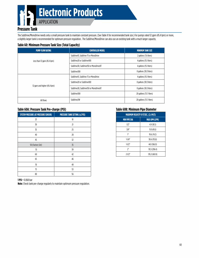
Electronic ProductsAPPLICATION
60
Pressure TankThe SubDrive/MonoDrive needs only a small pressure tank to maintain constant pressure. (See Table X for recommended tank size.) For pumps rated 12 gpm (45.4 lpm) or more, a slightly larger tank is recommended for optimum pressure regulation. The SubDrive/MonoDrive can also use an existing tank with a much larger capacity.
PUMP FLOW RATING CONTROLLER MODEL MINIMUM TANK SIZE
Less than 12 gpm (45.4 lpm)
SubDrive15, SubDrive 75 or MonoDrive 2 gallons (7.6 liters)
SubDrive20 or SubDrive100 4 gallons (15.1 liters)
SubDrive30, SubDrive150 or MonoDriveXT 4 gallons (15.1 liters)
SubDrive300 8 gallons (30.3 liters)
12 gpm and higher (45.4 lpm)
SubDrive15, SubDrive 75 or MonoDrive 4 gallons (15.1 liters)
SubDrive20 or SubDrive100 8 gallons (30.3 liters)
SubDrive30, SubDrive150 or MonoDriveXT 8 gallons (30.3 liters)
SubDrive300 20 gallons (75.7 liters)
All flows SubDrive2W 20 gallons (75.7 liters)
Table 60: Minimum Pressure Tank Size (Total Capacity)
SYSTEM PRESSURE (AT PRESSURE SENSOR) PRESSURE TANK SETTING (±2 PSI)
25 18
30 21
35 25
40 28
45 32
50 (Factory Set) 35
55 39
60 42
65 46
70 49
75 53
80 56
1 PSI = 0.068 bar Note: Check tank pre-charge regularly to maintain optimum pressure regulation.
Table 60A: Pressure Tank Pre-charge (PSI)MAXIMUM VELOCITY 8 FT/SEC. (2.4 M/S)
MIN PIPE DIA MAX GPM (LPM)
1/2" 4.9 (18.5)
3/4" 11.0 (41.6)
1" 19.6 (74.2)
1-1/4" 30.6 (115.8)
1-1/2" 44.1 (166.9)
2" 78.3 (296.4)
2-1/2" 176.3 (667.4)
Table 60B: Minimum Pipe Diameter
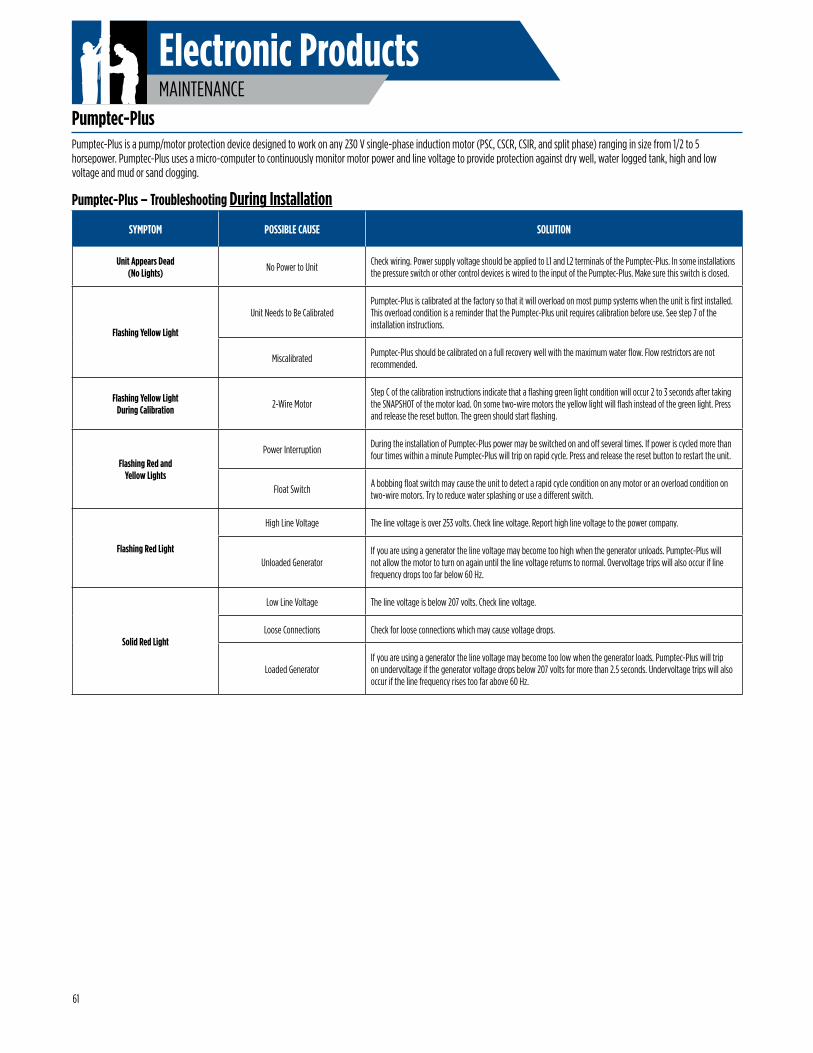
Electronic ProductsMAINTENANCE
Pumptec-PlusPumptec-Plus is a pump/motor protection device designed to work on any 230 V single-phase induction motor (PSC, CSCR, CSIR, and split phase) ranging in size from 1/2 to 5 horsepower. Pumptec-Plus uses a micro-computer to continuously monitor motor power and line voltage to provide protection against dry well, water logged tank, high and low voltage and mud or sand clogging.
Pumptec-Plus – Troubleshooting During Installation
SYMPTOM POSSIBLE CAUSE SOLUTION
Unit Appears Dead(No Lights) No Power to Unit
Check wiring. Power supply voltage should be applied to L1 and L2 terminals of the Pumptec-Plus. In some installations the pressure switch or other control devices is wired to the input of the Pumptec-Plus. Make sure this switch is closed.
Flashing Yellow Light
Unit Needs to Be CalibratedPumptec-Plus is calibrated at the factory so that it will overload on most pump systems when the unit is first installed. This overload condition is a reminder that the Pumptec-Plus unit requires calibration before use. See step 7 of the installation instructions.
MiscalibratedPumptec-Plus should be calibrated on a full recovery well with the maximum water flow. Flow restrictors are not recommended.
Flashing Yellow LightDuring Calibration 2-Wire Motor
Step C of the calibration instructions indicate that a flashing green light condition will occur 2 to 3 seconds after taking the SNAPSHOT of the motor load. On some two-wire motors the yellow light will flash instead of the green light. Press and release the reset button. The green should start flashing.
Flashing Red and Yellow Lights
Power InterruptionDuring the installation of Pumptec-Plus power may be switched on and off several times. If power is cycled more than four times within a minute Pumptec-Plus will trip on rapid cycle. Press and release the reset button to restart the unit.
Float SwitchA bobbing float switch may cause the unit to detect a rapid cycle condition on any motor or an overload condition on two-wire motors. Try to reduce water splashing or use a different switch.
Flashing Red Light
High Line Voltage The line voltage is over 253 volts. Check line voltage. Report high line voltage to the power company.
Unloaded GeneratorIf you are using a generator the line voltage may become too high when the generator unloads. Pumptec-Plus will not allow the motor to turn on again until the line voltage returns to normal. Overvoltage trips will also occur if line frequency drops too far below 60 Hz.
Solid Red Light
Low Line Voltage The line voltage is below 207 volts. Check line voltage.
Loose Connections Check for loose connections which may cause voltage drops.
Loaded GeneratorIf you are using a generator the line voltage may become too low when the generator loads. Pumptec-Plus will trip on undervoltage if the generator voltage drops below 207 volts for more than 2.5 seconds. Undervoltage trips will also occur if the line frequency rises too far above 60 Hz.
61
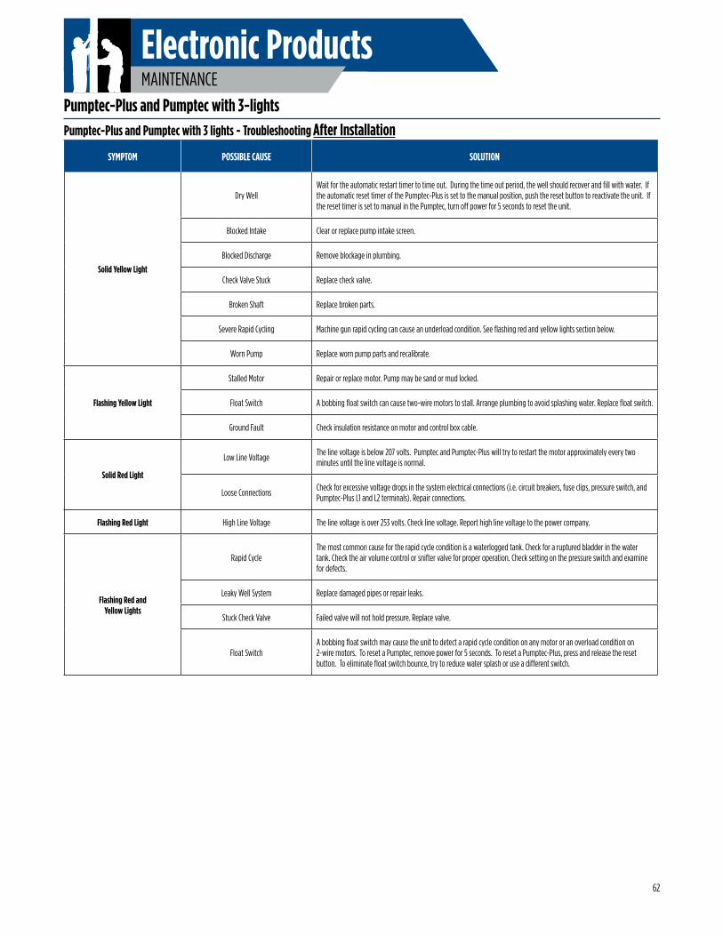
Electronic ProductsMAINTENANCE
Pumptec-Plus and Pumptec with 3-lightsPumptec-Plus and Pumptec with 3 lights - Troubleshooting After Installation
SYMPTOM POSSIBLE CAUSE SOLUTION
Solid Yellow Light
Dry WellWait for the automatic restart timer to time out. During the time out period, the well should recover and fill with water. If the automatic reset timer of the Pumptec-Plus is set to the manual position, push the reset button to reactivate the unit. If the reset timer is set to manual in the Pumptec, turn off power for 5 seconds to reset the unit.
Blocked Intake Clear or replace pump intake screen.
Blocked Discharge Remove blockage in plumbing.
Check Valve Stuck Replace check valve.
Broken Shaft Replace broken parts.
Severe Rapid Cycling Machine gun rapid cycling can cause an underload condition. See flashing red and yellow lights section below.
Worn Pump Replace worn pump parts and recalibrate.
Flashing Yellow Light
Stalled Motor Repair or replace motor. Pump may be sand or mud locked.
Float Switch A bobbing float switch can cause two-wire motors to stall. Arrange plumbing to avoid splashing water. Replace float switch.
Ground Fault Check insulation resistance on motor and control box cable.
Solid Red Light
Low Line VoltageThe line voltage is below 207 volts. Pumptec and Pumptec-Plus will try to restart the motor approximately every two minutes until the line voltage is normal.
Loose ConnectionsCheck for excessive voltage drops in the system electrical connections (i.e. circuit breakers, fuse clips, pressure switch, and Pumptec-Plus L1 and L2 terminals). Repair connections.
Flashing Red Light High Line Voltage The line voltage is over 253 volts. Check line voltage. Report high line voltage to the power company.
Flashing Red andYellow Lights
Rapid Cycle The most common cause for the rapid cycle condition is a waterlogged tank. Check for a ruptured bladder in the water tank. Check the air volume control or snifter valve for proper operation. Check setting on the pressure switch and examine for defects.
Leaky Well System Replace damaged pipes or repair leaks.
Stuck Check Valve Failed valve will not hold pressure. Replace valve.
Float SwitchA bobbing float switch may cause the unit to detect a rapid cycle condition on any motor or an overload condition on 2-wire motors. To reset a Pumptec, remove power for 5 seconds. To reset a Pumptec-Plus, press and release the reset button. To eliminate float switch bounce, try to reduce water splash or use a different switch.
62
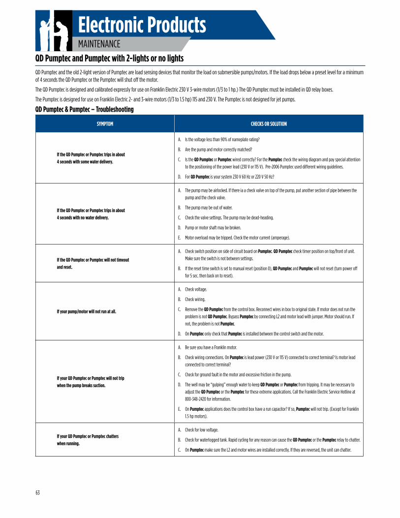
Electronic ProductsMAINTENANCE
QD Pumptec and Pumptec with 2-lights or no lights
QD Pumptec & Pumptec – Troubleshooting
SYMPTOM CHECKS OR SOLUTION
If the QD Pumptec or Pumptec trips in about 4 seconds with some water delivery.
A. Is the voltage less than 90% of nameplate rating?
B. Are the pump and motor correctly matched?
C. Is the QD Pumptec or Pumptec wired correctly? For the Pumptec check the wiring diagram and pay special attention to the positioning of the power lead (230 V or 115 V). Pre-2006 Pumptec used different wiring guidelines.
D. For QD Pumptec is your system 230 V 60 Hz or 220 V 50 Hz?
If the QD Pumptec or Pumptec trips in about4 seconds with no water delivery.
A. The pump may be airlocked. If there ia a check valve on top of the pump, put another section of pipe between the pump and the check valve.
B. The pump may be out of water.
C. Check the valve settings. The pump may be dead-heading.
D. Pump or motor shaft may be broken.
E. Motor overload may be tripped. Check the motor current (amperage).
If the QD Pumptec or Pumptec will not timeout and reset.
A. Check switch position on side of circuit board on Pumptec. QD Pumptec check timer position on top/front of unit. Make sure the switch is not between settings.
B. If the reset time switch is set to manual reset (position 0), QD Pumptec and Pumptec will not reset (turn power off for 5 sec. then back on to reset).
If your pump/motor will not run at all.
A. Check voltage.
B. Check wiring.
C. Remove the QD Pumptec from the control box. Reconnect wires in box to original state. If motor does not run the problem is not QD Pumptec. Bypass Pumptec by connecting L2 and motor lead with jumper. Motor should run. If not, the problem is not Pumptec.
D. On Pumptec only check that Pumptec is installed between the control switch and the motor.
If your QD Pumptec or Pumptec will not trip when the pump breaks suction.
A. Be sure you have a Franklin motor.
B. Check wiring connections. On Pumptec is lead power (230 V or 115 V) connected to correct terminal? Is motor lead connected to correct terminal?
C. Check for ground fault in the motor and excessive friction in the pump.
D. The well may be “gulping” enough water to keep QD Pumptec or Pumptec from tripping. It may be necessary to adjust the QD Pumptec or the Pumptec for these extreme applications. Call the Franklin Electric Service Hotline at 800-348-2420 for information.
E. On Pumptec applications does the control box have a run capacitor? If so, Pumptec will not trip. (Except for Franklin 1.5 hp motors).
If your QD Pumptec or Pumptec chatters when running.
A. Check for low voltage.
B. Check for waterlogged tank. Rapid cycling for any reason can cause the QD Pumptec or the Pumptec relay to chatter.
C. On Pumptec make sure the L2 and motor wires are installed correctly. If they are reversed, the unit can chatter.
QD Pumptec and the old 2-light version of Pumptec are load sensing devices that monitor the load on submersible pumps/motors. If the load drops below a preset level for a minimum of 4 seconds the QD Pumptec or the Pumptec will shut off the motor.
The QD Pumptec is designed and calibrated expressly for use on Franklin Electric 230 V 3-wire motors (1/3 to 1 hp.) The QD Pumptec must be installed in QD relay boxes.
The Pumptec is designed for use on Franklin Electric 2- and 3-wire motors (1/3 to 1.5 hp) 115 and 230 V. The Pumptec is not designed for jet pumps.
63
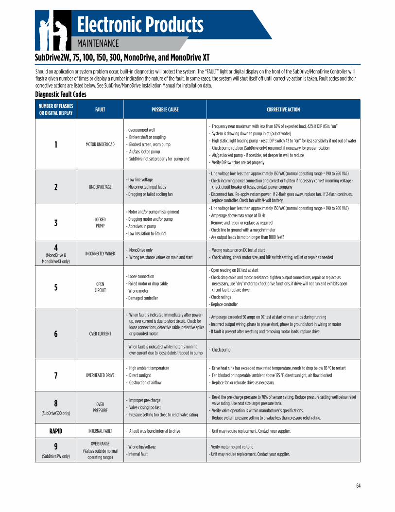
Electronic ProductsMAINTENANCE
NUMBER OF FLASHES OR DIGITAL DISPLAY
FAULT POSSIBLE CAUSE CORRECTIVE ACTION
1 MOTOR UNDERLOAD
- Overpumped well- Broken shaft or coupling- Blocked screen, worn pump- Air/gas locked pump- SubDrive not set properly for pump end
- Frequency near maximum with less than 65% of expected load, 42% if DIP #3 is “on”- System is drawing down to pump inlet (out of water)- High static, light loading pump - reset DIP switch #3 to “on” for less sensitivity if not out of water- Check pump rotation (SubDrive only) reconnect if necessary for proper rotation- Air/gas locked pump - if possible, set deeper in well to reduce- Verify DIP switches are set properly
2 UNDERVOLTAGE- Low line voltage- Misconnected input leads- Dragging or failed cooling fan
- Line voltage low, less than approximately 150 VAC (normal operating range = 190 to 260 VAC)- Check incoming power connection and correct or tighten if necessary correct incoming voltage -
check circuit breaker of fuses, contact power company- Disconnect fan. Re-apply system power. If 2-flash goes away, replace fan. If 2-flash continues,
replace controller. Check fan with 9-volt battery.
3 LOCKED PUMP
- Motor and/or pump misalignment- Dragging motor and/or pump- Abrasives in pump- Low Insulation to Ground
- Line voltage low, less than approximately 150 VAC (normal operating range = 190 to 260 VAC)- Amperage above max amps at 10 Hz- Remove and repair or replace as required- Check line to ground with a megohmmeter- Are output leads to motor longer than 1000 feet?
4 (MonoDrive &
MonoDriveXT only)
INCORRECTLY WIRED- MonoDrive only- Wrong resistance values on main and start
- Wrong resistance on DC test at start- Check wiring, check motor size, and DIP switch setting, adjust or repair as needed
5 OPEN CIRCUIT
- Loose connection- Failed motor or drop cable- Wrong motor- Damaged controller
- Open reading on DC test at start- Check drop cable and motor resistance, tighten output connections, repair or replace as
necesssary, use "dry" motor to check drive functions, if drive will not run and exhibits open circuit fault, replace drive
- Check ratings- Replace controller
6 OVER CURRENT
- When fault is indicated immediately after power-up, over current is due to short circuit. Check for loose connections, defective cable, defective splice or grounded motor.
- Amperage exceeded 50 amps on DC test at start or max amps during running- Incorrect output wiring, phase to phase short, phase to ground short in wiring or motor- If fault is present after resetting and removing motor leads, replace drive
- When fault is indicated while motor is running, over current due to loose debris trapped in pump
- Check pump
7 OVERHEATED DRIVE- High ambient temperature- Direct sunlight- Obstruction of airflow
- Drive heat sink has exceeded max rated temperature, needs to drop below 85 °C to restart- Fan blocked or inoperable, ambient above 125 °F, direct sunlight, air flow blocked- Replace fan or relocate drive as necessary
8(SubDrive300 only)
OVER PRESSURE
- Improper pre-charge- Valve closing too fast- Pressure setting too close to relief valve rating
- Reset the pre-charge pressure to 70% of sensor setting. Reduce pressure setting well below relief valve rating. Use next size larger pressure tank.
- Verify valve operation is within manufacturer’s specifications.- Reduce system pressure setting to a value less than pressure relief rating.
RAPID INTERNAL FAULT - A fault was found internal to drive - Unit may require replacement. Contact your supplier.
9(SubDrive2W only)
OVER RANGE(Values outside normal
operating range)
- Wrong hp/voltage- Internal fault
- Verify motor hp and voltage- Unit may require replacement. Contact your supplier.
Should an application or system problem occur, built-in diagnostics will protect the system. The “FAULT” light or digital display on the front of the SubDrive/MonoDrive Controller will flash a given number of times or display a number indicating the nature of the fault. In some cases, the system will shut itself off until corrective action is taken. Fault codes and their corrective actions are listed below. See SubDrive/MonoDrive Installation Manual for installation data.
SubDrive2W, 75, 100, 150, 300, MonoDrive, and MonoDrive XT
Diagnostic Fault Codes
64
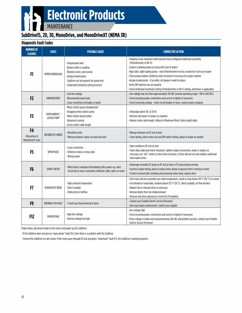
Electronic ProductsMAINTENANCE
Power down, disconnect leads to the motor and power up the SubDrive:
- If the SubDrive does not give an “open phase” fault (F5), then there is a problem with the SubDrive.
- Connect the SubDrive to a dry motor. If the motor goes through DC test and gives “underload” fault (F1), the SubDrive is working properly.
NUMBER OF FLASHES
FAULT POSSIBLE CAUSE CORRECTIVE ACTION
F1 MOTOR UNDERLOAD
- Overpumped well- Broken shaft or coupling- Blocked screen, worn pump- Air/gas locked pump- SubDrive not set properly for pump end- Underload Sensitivity setting incorrect
- Frequency near maximum with load less than configured underload sensitivity (Potentiometer or Wi-Fi)
- System is drawing down to pump inlet (out of water)- High static, light loading pump - reset Potentiometer for less sensitivity if not out of water- Check pump rotation (SubDrive only) reconnect if necessary for proper rotation- Air/gas locked pump - if possible, set deeper in well to reduce- Verify DIP switches are set properly- Check Underload Sensitivity Setting (Potentiometer or Wi-Fi setting, whichever is applicable)
F2 UNDERVOLTAGE- Low line voltage- Misconnected input leads- Loose connection at breaker or panel
- Line voltage low, less than approximately 150 VAC (normal operating range = 190 to 260 VAC)- Check incoming power connections and correct or tighten if necessary- Correct incoming voltage - check circuit breaker or fuses, contact power company
F3 OVERCURRENT / LOCKED PUMP
- Motor and/or pump misalignment- Dragging motor and/or pump- Motor and/or pump locked- Abrasives in pump- Excess motor cable length
- Amperage above SFL at 30 Hz- Remove and repair or replace as required- Reduce motor cable length. Adhere to Maximum Motor Cable Length table.
F4(MonoDrive &
MonoDriveXT only)
INCORRECTLY WIRED- MonoDrive only- Wrong resistance values on main and start
- Wrong resistance on DC test at start- Check wiring, check motor size and DIP switch setting, adjust or repair as needed
F5 OPEN PHASE- Loose connection- Defective motor or drop cable- Wrong motor
- Open reading on DC test at start.- Check drop cable and motor resistance, tighten output connections, repair or replace as
necessary, use “dry” motor to check drive functions. If drive will not run and exhibits underload fault replace drive
F6 SHORT CIRCUIT- When fault is indicated immediately after power-up, short
circuit due to loose connection, defective cable, splice or motor
- Amperage exceeded 25 amps on DC test at start or SF amps during running- Incorrect output wiring, phase to phase short, phase to ground short in wiring or motor- If fault is present after resetting and removing motor leads, replace drive
F7 OVERHEATED DRIVE- High ambient temperature- Direct sunlight- Obstruction of airflow
- Drive heat sink has exceeded max rated temperature, needs to drop below 194 °F (90 °C) to restart- Fan blocked or inoperable, ambient above 122 °F (50 °C), direct sunlight, air flow blocked- Replace fan or relocate drive as necessary- Remove debris from fan intake/exhaust- Remove and clean optional air screen kit (if installed)
F9 INTERNAL PCB FAULT - A fault was found internal to drive- Contact your Franklin Electric Service Personnel- Unit may require replacement. Contact your supplier.
F12 OVERVOLTAGE- High line voltage- Internal voltage too high
- Line voltage high- Check incoming power connections and correct or tighten if necessary- If line voltage is stable and measured below 260 VAC and problem persists, contact your Franklin
Electric Service Personnel
Diagnostic Fault Codes
SubDrive15, 20, 30, MonoDrive, and MonoDriveXT (NEMA 3R)
65
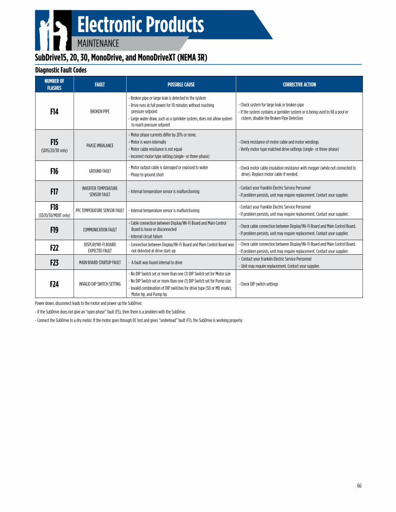
Electronic ProductsMAINTENANCE
NUMBER OF FLASHES
FAULT POSSIBLE CAUSE CORRECTIVE ACTION
F14 BROKEN PIPE
- Broken pipe or large leak is detected in the system- Drive runs at full power for 10 minutes without reaching
pressure setpoint- Large water draw, such as a sprinkler system, does not allow system
to reach pressure setpoint
- Check system for large leak or broken pipe- If the system contains a sprinkler system or is being used to fill a pool or
cistern, disable the Broken Pipe Detection
F15(SD15/20/30 only)
PHASE IMBALANCE
- Motor phase currents differ by 20% or more.- Motor is worn internally- Motor cable resistance is not equal- Incorrect motor type setting (single- or three-phase)
- Check resistance of motor cable and motor windings- Verify motor type matched drive settings (single- or three-phase)
F16 GROUND FAULT- Motor output cable is damaged or exposed to water- Phase to ground short
- Check motor cable insulation resistance with megger (while not connected to drive). Replace motor cable if needed.
F17 INVERTER TEMPERATURE SENSOR FAULT
- Internal temperature sensor is malfunctioning- Contact your Franklin Electric Service Personnel- If problem persists, unit may require replacement. Contact your supplier.
F18(SD20/30/MDXT only)
PFC TEMPERATURE SENSOR FAULT - Internal temperature sensor is malfunctioning- Contact your Franklin Electric Service Personnel- If problem persists, unit may require replacement. Contact your supplier.
F19 COMMUNICATION FAULT- Cable connection between Display/Wi-Fi Board and Main Control
Board is loose or disconnected- Internal circuit failure
- Check cable connection between Display/Wi-Fi Board and Main Control Board.- If problem persists, unit may require replacement. Contact your supplier.
F22 DISPLAY/WI-FI BOARD EXPECTED FAULT
- Connection between Display/Wi-Fi Board and Main Control Board was not detected at drive start-up
- Check cable connection between Display/Wi-Fi Board and Main Control Board.- If problem persists, unit may require replacement. Contact your supplier.
F23 MAIN BOARD STARTUP FAULT - A fault was found internal to drive- Contact your Franklin Electric Service Personnel- Unit may require replacement. Contact your supplier.
F24 INVALID DIP SWITCH SETTING
- No DIP Switch set or more than one (1) DIP Switch set for Motor size- No DIP Switch set or more than one (1) DIP Switch set for Pump size- Invalid combination of DIP switches for drive type (SD or MD mode),
Motor hp, and Pump hp.
- Check DIP switch settings
Diagnostic Fault Codes
Power down, disconnect leads to the motor and power up the SubDrive:
- If the SubDrive does not give an “open phase” fault (F5), then there is a problem with the SubDrive.
- Connect the SubDrive to a dry motor. If the motor goes through DC test and gives “underload” fault (F1), the SubDrive is working properly.
SubDrive15, 20, 30, MonoDrive, and MonoDriveXT (NEMA 3R)
66
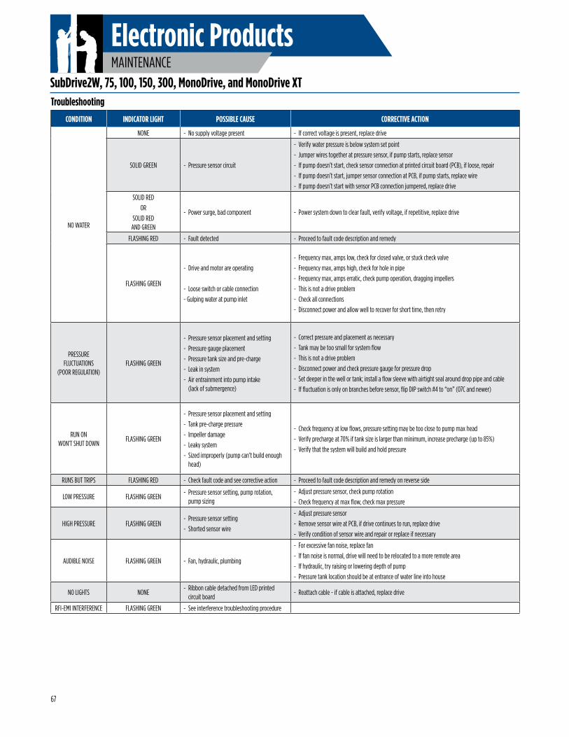
Electronic ProductsMAINTENANCE
Troubleshooting
SubDrive2W, 75, 100, 150, 300, MonoDrive, and MonoDrive XT
CONDITION INDICATOR LIGHT POSSIBLE CAUSE CORRECTIVE ACTION
NO WATER
NONE - No supply voltage present - If correct voltage is present, replace drive
SOLID GREEN - Pressure sensor circuit
- Verify water pressure is below system set point- Jumper wires together at pressure sensor, if pump starts, replace sensor- If pump doesn’t start, check sensor connection at printed circuit board (PCB), if loose, repair- If pump doesn’t start, jumper sensor connection at PCB, if pump starts, replace wire- If pump doesn’t start with sensor PCB connection jumpered, replace drive
SOLID REDOR
SOLID RED AND GREEN
- Power surge, bad component - Power system down to clear fault, verify voltage, if repetitive, replace drive
FLASHING RED - Fault detected - Proceed to fault code description and remedy
FLASHING GREEN
- Drive and motor are operating
- Loose switch or cable connection- Gulping water at pump inlet
- Frequency max, amps low, check for closed valve, or stuck check valve- Frequency max, amps high, check for hole in pipe- Frequency max, amps erratic, check pump operation, dragging impellers- This is not a drive problem- Check all connections- Disconnect power and allow well to recover for short time, then retry
PRESSURE FLUCTUATIONS
(POOR REGULATION)FLASHING GREEN
- Pressure sensor placement and setting- Pressure gauge placement- Pressure tank size and pre-charge- Leak in system- Air entrainment into pump intake
(lack of submergence)
- Correct pressure and placement as necessary- Tank may be too small for system flow- This is not a drive problem- Disconnect power and check pressure gauge for pressure drop- Set deeper in the well or tank; install a flow sleeve with airtight seal around drop pipe and cable- If fluctuation is only on branches before sensor, flip DIP switch #4 to “on” (07C and newer)
RUN ON WON’T SHUT DOWN
FLASHING GREEN
- Pressure sensor placement and setting- Tank pre-charge pressure- Impeller damage- Leaky system- Sized improperly (pump can’t build enough
head)
- Check frequency at low flows, pressure setting may be too close to pump max head- Verify precharge at 70% if tank size is larger than minimum, increase precharge (up to 85%)- Verify that the system will build and hold pressure
RUNS BUT TRIPS FLASHING RED - Check fault code and see corrective action - Proceed to fault code description and remedy on reverse side
LOW PRESSURE FLASHING GREEN- Pressure sensor setting, pump rotation,
pump sizing- Adjust pressure sensor, check pump rotation- Check frequency at max flow, check max pressure
HIGH PRESSURE FLASHING GREEN- Pressure sensor setting- Shorted sensor wire
- Adjust pressure sensor- Remove sensor wire at PCB, if drive continues to run, replace drive- Verify condition of sensor wire and repair or replace if necessary
AUDIBLE NOISE FLASHING GREEN - Fan, hydraulic, plumbing
- For excessive fan noise, replace fan- If fan noise is normal, drive will need to be relocated to a more remote area- If hydraulic, try raising or lowering depth of pump- Pressure tank location should be at entrance of water line into house
NO LIGHTS NONE- Ribbon cable detached from LED printed
circuit board- Reattach cable - if cable is attached, replace drive
RFI-EMI INTERFERENCE FLASHING GREEN - See interference troubleshooting procedure
67
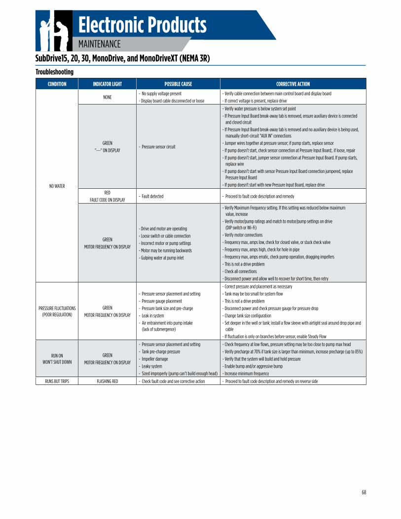
Electronic ProductsMAINTENANCE
Troubleshooting
CONDITION INDICATOR LIGHT POSSIBLE CAUSE CORRECTIVE ACTION
NO WATER
NONE- No supply voltage present- Display board cable disconnected or loose
- Verify cable connection between main control board and display board- If correct voltage is present, replace drive
GREEN"---" ON DISPLAY
- Pressure sensor circuit
- Verify water pressure is below system set point- If Pressure Input Board break-away tab is removed, ensure auxiliary device is connected
and closed circuit- If Pressure Input Board break-away tab is removed and no auxiliary device is being used,
manually short-circuit "AUX IN" connections- Jumper wires together at pressure sensor; if pump starts, replace sensor- If pump doesn’t start, check sensor connection at Pressure Input Board;. if loose, repair- If pump doesn’t start, jumper sensor connection at Pressure Input Board. If pump starts,
replace wire- If pump doesn’t start with sensor Pressure Input Board connection jumpered, replace
Pressure Input Board- If pump doesn't start with new Pressure Input Board, replace drive
REDFAULT CODE ON DISPLAY
- Fault detected - Proceed to fault code description and remedy
GREENMOTOR FREQUENCY ON DISPLAY
- Drive and motor are operating- Loose switch or cable connection- Incorrect motor or pump settings- Motor may be running backwards- Gulping water at pump inlet
- Verify Maximum Frequency setting. If this setting was reduced below maximum value, increase
- Verify motor/pump ratings and match to motor/pump settings on drive (DIP switch or Wi-Fi)
- Verify motor connections- Frequency max, amps low, check for closed valve, or stuck check valve- Frequency max, amps high, check for hole in pipe- Frequency max, amps erratic, check pump operation, dragging impellers- This is not a drive problem- Check all connections- Disconnect power and allow well to recover for short time, then retry
PRESSURE FLUCTUATIONS (POOR REGULATION)
GREENMOTOR FREQUENCY ON DISPLAY
- Pressure sensor placement and setting- Pressure gauge placement- Pressure tank size and pre-charge- Leak in system- Air entrainment into pump intake
(lack of submergence)
- Correct pressure and placement as necessary- Tank may be too small for system flow- This is not a drive problem- Disconnect power and check pressure gauge for pressure drop- Change tank size configuration- Set deeper in the well or tank; install a flow sleeve with airtight seal around drop pipe and
cable- If fluctuation is only on branches before sensor, enable Steady Flow
RUN ON WON’T SHUT DOWN
GREENMOTOR FREQUENCY ON DISPLAY
- Pressure sensor placement and setting- Tank pre-charge pressure- Impeller damage- Leaky system- Sized improperly (pump can’t build enough head)
- Check frequency at low flows, pressure setting may be too close to pump max head- Verify precharge at 70% if tank size is larger than minimum, increase precharge (up to 85%)- Verify that the system will build and hold pressure- Enable bump and/or aggressive bump- Increase minimum frequency
RUNS BUT TRIPS FLASHING RED - Check fault code and see corrective action - Proceed to fault code description and remedy on reverse side
SubDrive15, 20, 30, MonoDrive, and MonoDriveXT (NEMA 3R)
68
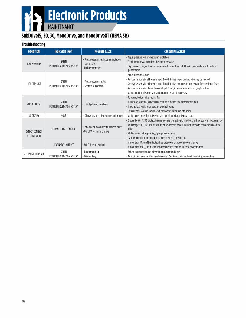
Electronic ProductsMAINTENANCE
Troubleshooting
SubDrive15, 20, 30, MonoDrive, and MonoDriveXT (NEMA 3R)
CONDITION INDICATOR LIGHT POSSIBLE CAUSE CORRECTIVE ACTION
LOW PRESSUREGREEN
MOTOR FREQUENCY ON DISPLAY
- Pressure sensor setting, pump rotation, pump sizing
- High temperature
- Adjust pressure sensor, check pump rotation- Check frequency at max flow, check max pressure- High ambient and/or drive temperature will cause drive to foldback power and run with reduced
performance
HIGH PRESSUREGREEN
MOTOR FREQUENCY ON DISPLAY - Pressure sensor setting- Shorted sensor wire
- Adjust pressure sensor- Remove sensor wire at Pressure Input Board, if drive stops running, wire may be shorted- Remove sensor wire at Pressure Input Board, if drive continues to run, replace Pressure Input Board- Remove sensor wire at new Pressure Input Board, if drive continues to run, replace drive- Verify condition of sensor wire and repair or replace if necessary
AUDIBLE NOISEGREEN
MOTOR FREQUENCY ON DISPLAY- Fan, hydraulic, plumbing
- For excessive fan noise, replace fan- If fan noise is normal, drive will need to be relocated to a more remote area- If hydraulic, try raising or lowering depth of pump- Pressure tank location should be at entrance of water line into house
NO DISPLAY NONE - Display board cable disconnected or loose - Verify cable connection between main control board and display board
CANNOT CONNECT TO DRIVE WI-FI
FE CONNECT LIGHT ON SOLID- Attempting to connect to incorrect drive- Out of Wi-Fi range of drive
- Ensure the Wi-Fi SSID (hotspot name) you are connecting to matches the drive you wish to connect to- Wi-Fi range is 100 feet line-of-site, must be closer to drive if walls or floors are between you and the
drive- Wi-Fi module not responding, cycle power to drive- Cycle Wi-Fi radio on mobile device, refresh Wi-Fi connection list
FE CONNECT LIGHT OFF - Wi-Fi timeout expired- If more than fifteen (15) minutes since last power cycle, cycle power to drive- If more than one (1) hour since last disconnection from Wi-Fi, cycle power to drive
RFI-EMI INTERFERENCEGREEN
MOTOR FREQUENCY ON DISPLAY- Poor grounding- Wire routing
- Adhere to grounding and wire routing recommendations- An additional external filter may be needed. See Accessories section for ordering information
69
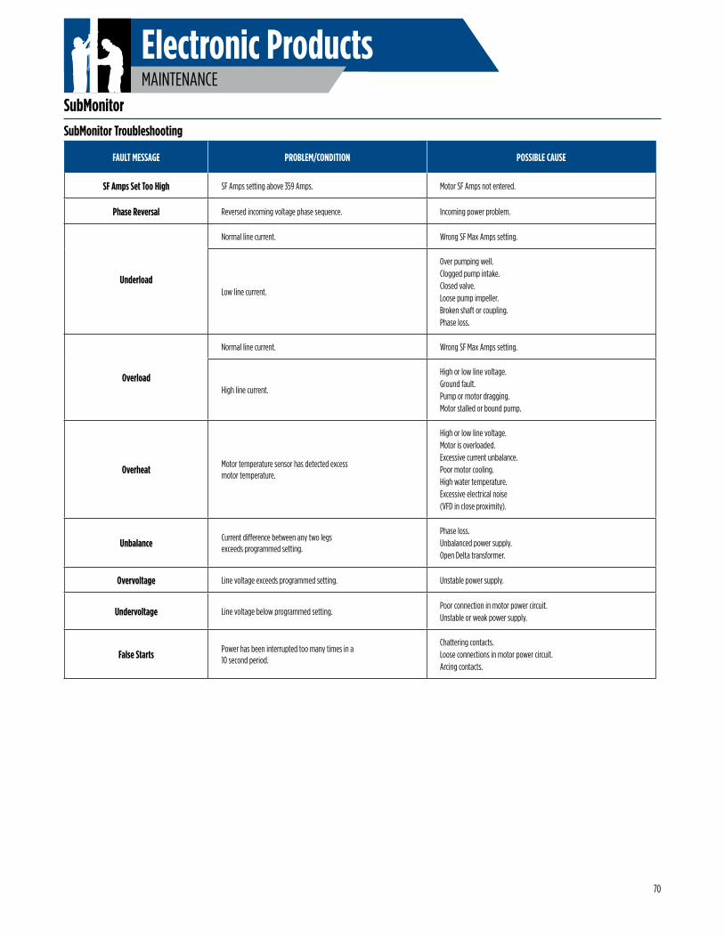
Electronic ProductsMAINTENANCE
SubMonitorSubMonitor Troubleshooting
FAULT MESSAGE PROBLEM/CONDITION POSSIBLE CAUSE
SF Amps Set Too High SF Amps setting above 359 Amps. Motor SF Amps not entered.
Phase Reversal Reversed incoming voltage phase sequence. Incoming power problem.
Underload
Normal line current. Wrong SF Max Amps setting.
Low line current.
Over pumping well.Clogged pump intake.Closed valve.Loose pump impeller.Broken shaft or coupling.Phase loss.
Overload
Normal line current. Wrong SF Max Amps setting.
High line current.
High or low line voltage.Ground fault.Pump or motor dragging.Motor stalled or bound pump.
Overheat Motor temperature sensor has detected excess motor temperature.
High or low line voltage.Motor is overloaded.Excessive current unbalance.Poor motor cooling.High water temperature.Excessive electrical noise(VFD in close proximity).
Unbalance Current difference between any two legs exceeds programmed setting.
Phase loss.Unbalanced power supply.Open Delta transformer.
Overvoltage Line voltage exceeds programmed setting. Unstable power supply.
Undervoltage Line voltage below programmed setting.Poor connection in motor power circuit.Unstable or weak power supply.
False Starts Power has been interrupted too many times in a 10 second period.
Chattering contacts.Loose connections in motor power circuit.Arcing contacts.
70
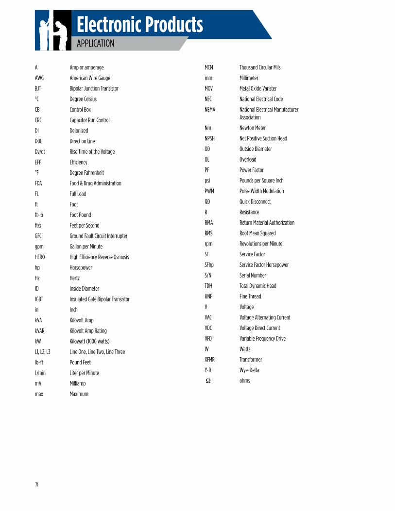
Electronic ProductsAPPLICATION
A Amp or amperage
AWG American Wire Gauge
BJT Bipolar Junction Transistor
°C Degree Celsius
CB Control Box
CRC Capacitor Run Control
DI Deionized
DOL Direct on Line
Dv/dt Rise Time of the Voltage
EFF Efficiency
°F Degree Fahrenheit
FDA Food & Drug Administration
FL Full Load
ft Foot
ft-lb Foot Pound
ft/s Feet per Second
GFCI Ground Fault Circuit Interrupter
gpm Gallon per Minute
HERO High Efficiency Reverse Osmosis
hp Horsepower
Hz Hertz
ID Inside Diameter
IGBT Insulated Gate Bipolar Transistor
in Inch
kVA Kilovolt Amp
kVAR Kilovolt Amp Rating
kW Kilowatt (1000 watts)
L1, L2, L3 Line One, Line Two, Line Three
lb-ft Pound Feet
L/min Liter per Minute
mA Milliamp
max Maximum
MCM Thousand Circular Mils
mm Millimeter
MOV Metal Oxide Varister
NEC National Electrical Code
NEMA National Electrical Manufacturer Association
Nm Newton Meter
NPSH Net Positive Suction Head
OD Outside Diameter
OL Overload
PF Power Factor
psi Pounds per Square Inch
PWM Pulse Width Modulation
QD Quick Disconnect
R Resistance
RMA Return Material Authorization
RMS Root Mean Squared
rpm Revolutions per Minute
SF Service Factor
SFhp Service Factor Horsepower
S/N Serial Number
TDH Total Dynamic Head
UNF Fine Thread
V Voltage
VAC Voltage Alternating Current
VDC Voltage Direct Current
VFD Variable Frequency Drive
W Watts
XFMR Transformer
Y-D Wye-Delta
Ω ohms
71

AIM MANUAL
Notes

AIM MANUAL
Notes


YOU JUST GOT A LITTLE MORE HELP FROM A FRIEND.
FRANKLIN ELECTRIC TECHNICAL SERVICE HOTLINE 800-348-2420 | 260-827-5102 FAX
Option 1 - Franklin Water | Option 2 - Franklin Control System | Option 3 - Little Giant Commercial
MF1311 12-14franklinwater.com
Call Franklin’s toll free TECHNICAL SERVICE HOTLINE for answers to your pump and motor installation questions. When you call, a Franklin expert will offer assistance in troubleshooting and provide immediate answers to your system application questions. Technical support is also available online.
franklinwater.com | franklin-controls.com | solar.franklin-electric.com | constantpressure.com
2015 EDITION