Embed Size (px)
Citation preview
SNC7A000000000J2323ABAT00
SUPPLEMENTAL RESTRAINT SYSTEM (SRS) (If Audio, Navigation, and Telematicsmaintenance is required)
The Civic Hybrid SRS includes a driver’s airbag in the steering wheel hub, a passenger’s airbag in the dashboardabove the glove box, seat belt tensioners in the front seat belt retractors, seat belt buckle tensioners in the front seatbelt buckles, side curtain airbags in the sides of the roof, and side airbags in the front seat-backs. Informationnecessary to safely service the SRS is included in this Service Manual. Items marked with an asterisk ( ) on thecontents page include or are located near SRS components. Servicing, disassembling, or replacing these itemsrequires special precautions and tools, and should be done only by an authorized Honda dealer.
• To avoid rendering the SRS inoperative, which could lead to personal injury or death in the event of a severe frontalor side collision, all SRS service work should be done by an authorized Honda dealer.
• Improper service procedures, including incorrect removal and installation of the SRS, could lead to personal injurycaused by unintentional deployment of the airbags and/or side airbags.
• Do not bump or impact the SRS unit, front impact sensors, or side impact sensors when the ignition switch is ON (II),or for at least 3 minutes after the ignition switch is turned OFF; otherwise, the system may fail in a collision, or theairbags may deploy.
• SRS electrical connectors are identified by yellow color coding. Related components are located in the steeringcolumn, front console, dashboard, dashboard lower panel, in the dashboard above the glove box, in the front seats,in the roof side, and around the floor. Do not use electrical test equipment on these circuits.
06/09/19 10:34:57 61SNC010_230_0001
SNC7A000000000J2323ZCAT00
Audio, Navigation, and Telematics
Audio System
Navigation System
................................................................................................................................Special Tools . 23-2
......................................................................
.................................................................................................................
...............................................................................................................
....................................................................................
.............................................................
......................................................................
...................................................................
...............................................................
......................................................................
.................................................................................................................
...............................................................................................................
....................................................................................
.............................................................
......................................................................
...................................................................
...............................................................
Component Location Index . 23-3Symptom Troubleshooting Index . 23-4System Description . 23-6Circuit Diagram . 23-16Self-diagnostic Function . 23-20Error Codes . 23-22Symptom Troubleshooting . 23-23Sound Quality Diagnosis . 23-54Audio Unit Removal/Installation . 23-59XM Receiver Removal/Installation . 23-60Speaker Replacement . 23-61Auxiliary Jack Assembly Replacement . 23-62Audio Remote Switch Test . 23-63Audio Remote Switch Replacement . 23-63AM/FM Antenna Replacement . 23-64AM/FM/XM Antenna Replacement . 23-64
..............................................................
...................................................................................
....................................................................................................
..........................................................
..................................................................
.....................................................................
...........................
Component Location Index . 23-65General Troubleshooting Information . 23-66Symptom Troubleshooting Index . 23-69System Description . 23-71Circuit Diagram . 23-88Symptom Troubleshooting . 23-89System Diagnostic Mode . 23-103CD, DVD and PC card Removal/Installation . 23-121Navigation Unit Removal/Installation . 23-122Voice Control Switch Test . 23-123Voice Control Switch Replacement . 23-123Microphone Replacement . 23-124GPS Antenna Removal/Installation . 23-124
06/09/19 10:34:57 61SNC010_230_0002
01
SNC7A000000000J2323PAAT00
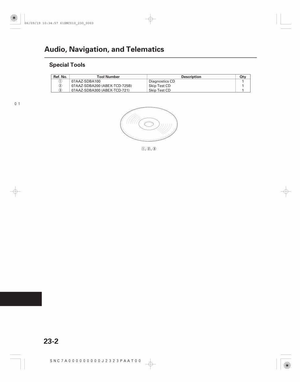
Ref. No. Tool Number Description Qty
23-2
Audio, Navigation, and Telematics
Special Tools
07AAZ-SDBA100 Diagnostics CD 107AAZ-SDBA200 (ABEX-TCD-725B) Skip Test CD 107AAZ-SDBA300 (ABEX-TCD-721) Skip Test CD 1
, ,
06/09/19 10:34:57 61SNC010_230_0003
*01
SNC7A00J10300000000DAAT80
23-3
Audio System
Component Location Index
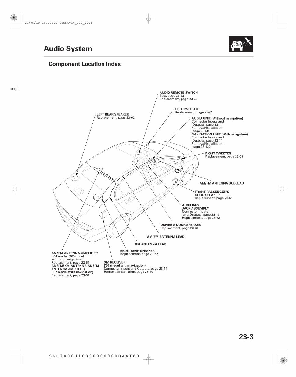
RIGHT TWEETER
AUXILIARYJACK ASSEMBLY
AUDIO UNIT (Without navigation)
LEFT TWEETER
AUDIO REMOTE SWITCH
LEFT REAR SPEAKER
AM/FM ANTENNA SUBLEAD
DRIVER’S DOOR SPEAKER
AM/FM ANTENNA LEAD
RIGHT REAR SPEAKERAM/FM ANTENNA-AMPLIFIER(’06 model, ’07 modelwithout navigation)
NAVIGATION UNIT (With navigation)
FRONT PASSENGER’SDOOR SPEAKER
XM ANTENNA LEAD
AM/FM/XM ANTENNA-AM/FMANTENNA AMPLIFIER(’07 model with navigation)
XM RECEIVER(’07 model with navigation)
Replacement, page 23-61
Connector Inputsand Outputs, page 23-15Replacement, page 23-62
Connector Inputs andOutputs, page 23-11Removal/Installation,page 23-59
Replacement, page 23-61
Test, page 23-63Replacement, page 23-63
Replacement, page 23-62
Replacement, page 23-61
Replacement, page 23-62
Replacement, page 23-64
Connector Inputs andOutputs, page 23-11Removal/Installation,page 23-122
Replacement, page 23-61
Replacement, page 23-64
Connector Inputs and Outputs, page 23-14Removal/Installation, page 23-60
06/09/19 10:35:02 61SNC010_230_0004
SNC7A00J10300000000HBAT01
Symptom Diagnostic procedure Also check for
23-4
Audio System
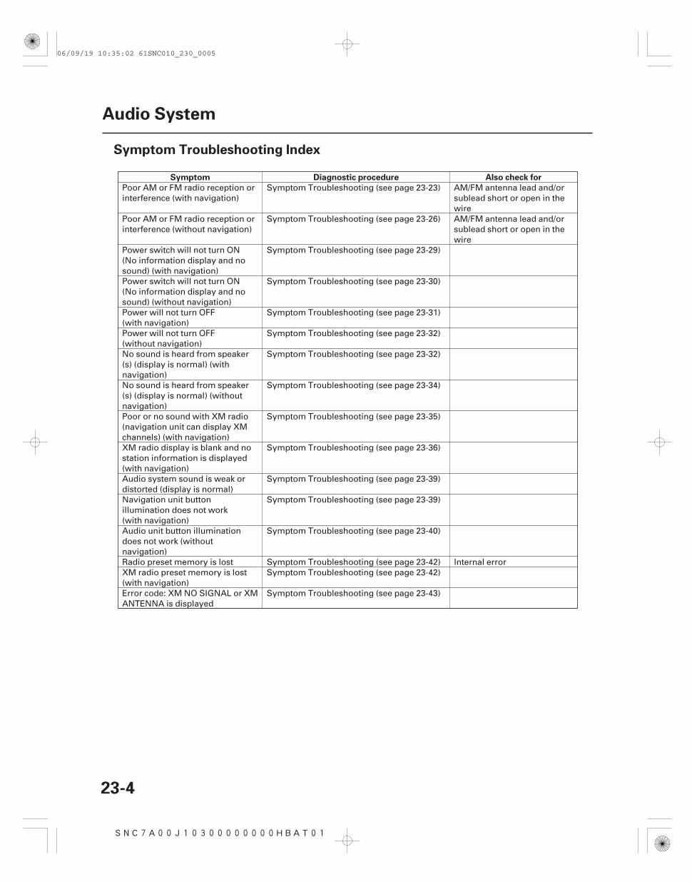
Symptom Troubleshooting Index
Poor AM or FM radio reception orinterference (with navigation)
Symptom Troubleshooting (see page 23-23) AM/FM antenna lead and/orsublead short or open in thewire
Poor AM or FM radio reception orinterference (without navigation)
Symptom Troubleshooting (see page 23-26) AM/FM antenna lead and/orsublead short or open in thewire
Power switch will not turn ON(No information display and nosound) (with navigation)
Symptom Troubleshooting (see page 23-29)
Power switch will not turn ON(No information display and nosound) (without navigation)
Symptom Troubleshooting (see page 23-30)
Power will not turn OFF(with navigation)
Symptom Troubleshooting (see page 23-31)
Power will not turn OFF(without navigation)
Symptom Troubleshooting (see page 23-32)
No sound is heard from speaker(s) (display is normal) (withnavigation)
Symptom Troubleshooting (see page 23-32)
No sound is heard from speaker(s) (display is normal) (withoutnavigation)
Symptom Troubleshooting (see page 23-34)
Poor or no sound with XM radio(navigation unit can display XMchannels) (with navigation)
Symptom Troubleshooting (see page 23-35)
XM radio display is blank and nostation information is displayed(with navigation)
Symptom Troubleshooting (see page 23-36)
Audio system sound is weak ordistorted (display is normal)
Symptom Troubleshooting (see page 23-39)
Navigation unit buttonillumination does not work(with navigation)
Symptom Troubleshooting (see page 23-39)
Audio unit button illuminationdoes not work (withoutnavigation)
Symptom Troubleshooting (see page 23-40)
Radio preset memory is lost Symptom Troubleshooting (see page 23-42) Internal errorXM radio preset memory is lost(with navigation)
Symptom Troubleshooting (see page 23-42)
Error code: XM NO SIGNAL or XMANTENNA is displayed
Symptom Troubleshooting (see page 23-43)
06/09/19 10:35:02 61SNC010_230_0005
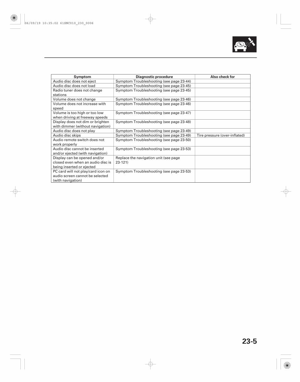
Symptom Diagnostic procedure Also check for
23-5
Audio disc does not eject Symptom Troubleshooting (see page 23-44)Audio disc does not load Symptom Troubleshooting (see page 23-45)Radio tuner does not changestations
Symptom Troubleshooting (see page 23-45)
Volume does not change Symptom Troubleshooting (see page 23-46)Volume does not increase withspeed
Symptom Troubleshooting (see page 23-46)
Volume is too high or too lowwhen driving at freeway speeds
Symptom Troubleshooting (see page 23-47)
Display does not dim or brightenwith dimmer (without navigation)
Symptom Troubleshooting (see page 23-48)
Audio disc does not play Symptom Troubleshooting (see page 23-49)Audio disc skips Symptom Troubleshooting (see page 23-49) Tire pressure (over-inflated)Audio remote switch does notwork properly
Symptom Troubleshooting (see page 23-50)
Audio disc cannot be insertedand/or ejected (with navigation)
Symptom Troubleshooting (see page 23-53)
Display can be opened and/orclosed even when an audio disc isbeing inserted or ejected
Replace the navigation unit (see page23-121)
PC card will not play/card icon onaudio screen cannot be selected(with navigation)
Symptom Troubleshooting (see page 23-53)
06/09/19 10:35:02 61SNC010_230_0006
SNC7A00J10311100000CAAT01
Overview
Speed-sensitive volume compensation (SVC)
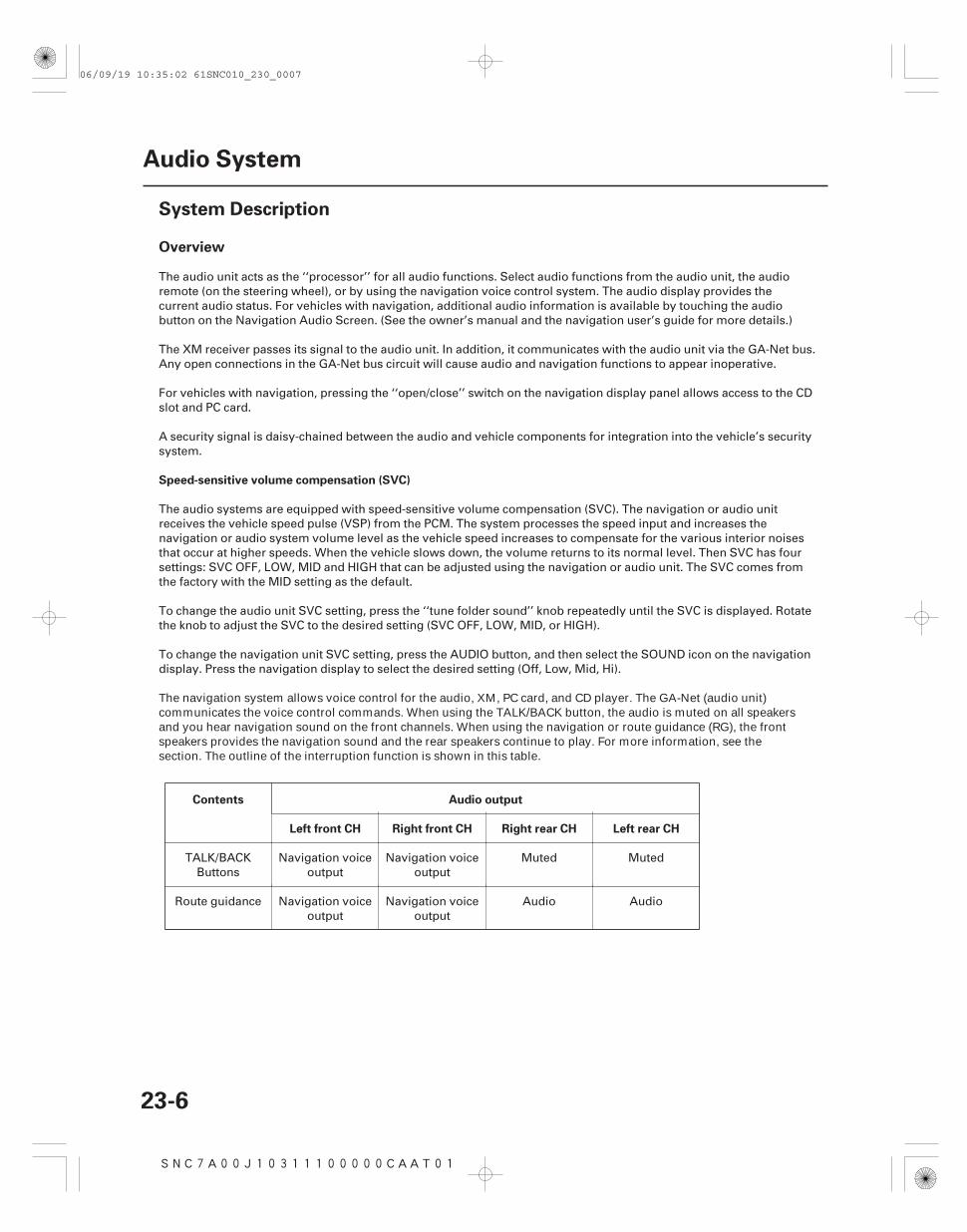
Contents Audio output
Left front CH Right front CH Right rear CH Left rear CH
23-6
Audio System
System Description
The audio unit acts as the ‘‘processor’’ for all audio functions. Select audio functions from the audio unit, the audioremote (on the steering wheel), or by using the navigation voice control system. The audio display provides thecurrent audio status. For vehicles with navigation, additional audio information is available by touching the audiobutton on the Navigation Audio Screen. (See the owner’s manual and the navigation user’s guide for more details.)
The XM receiver passes its signal to the audio unit. In addition, it communicates with the audio unit via the GA-Net bus.Any open connections in the GA-Net bus circuit will cause audio and navigation functions to appear inoperative.
For vehicles with navigation, pressing the ‘‘open/close’’ switch on the navigation display panel allows access to the CDslot and PC card.
A security signal is daisy-chained between the audio and vehicle components for integration into the vehicle’s securitysystem.
The audio systems are equipped with speed-sensitive volume compensation (SVC). The navigation or audio unitreceives the vehicle speed pulse (VSP) from the PCM. The system processes the speed input and increases thenavigation or audio system volume level as the vehicle speed increases to compensate for the various interior noisesthat occur at higher speeds. When the vehicle slows down, the volume returns to its normal level. Then SVC has foursettings: SVC OFF, LOW, MID and HIGH that can be adjusted using the navigation or audio unit. The SVC comes fromthe factory with the MID setting as the default.
To change the audio unit SVC setting, press the ‘‘tune folder sound’’ knob repeatedly until the SVC is displayed. Rotatethe knob to adjust the SVC to the desired setting (SVC OFF, LOW, MID, or HIGH).
To change the navigation unit SVC setting, press the AUDIO button, and then select the SOUND icon on the navigationdisplay. Press the navigation display to select the desired setting (Off, Low, Mid, Hi).
The navigation system allows voice control for the audio, XM, PC card, and CD player. The GA-Net (audio unit)communicates the voice control commands. When using the TALK/BACK button, the audio is muted on all speakersand you hear navigation sound on the front channels. When using the navigation or route guidance (RG), the front speakers provides the navigation sound and the rear speakers continue to play. For more information, see the section. The outline of the interruption function is shown in this table.
TALK/BACKButtons
Navigation voiceoutput
Navigation voiceoutput
Muted Muted
Route guidance Navigation voiceoutput
Navigation voiceoutput
Audio Audio
06/09/19 10:35:02 61SNC010_230_0007
*01
GA-Net Bus Configuration
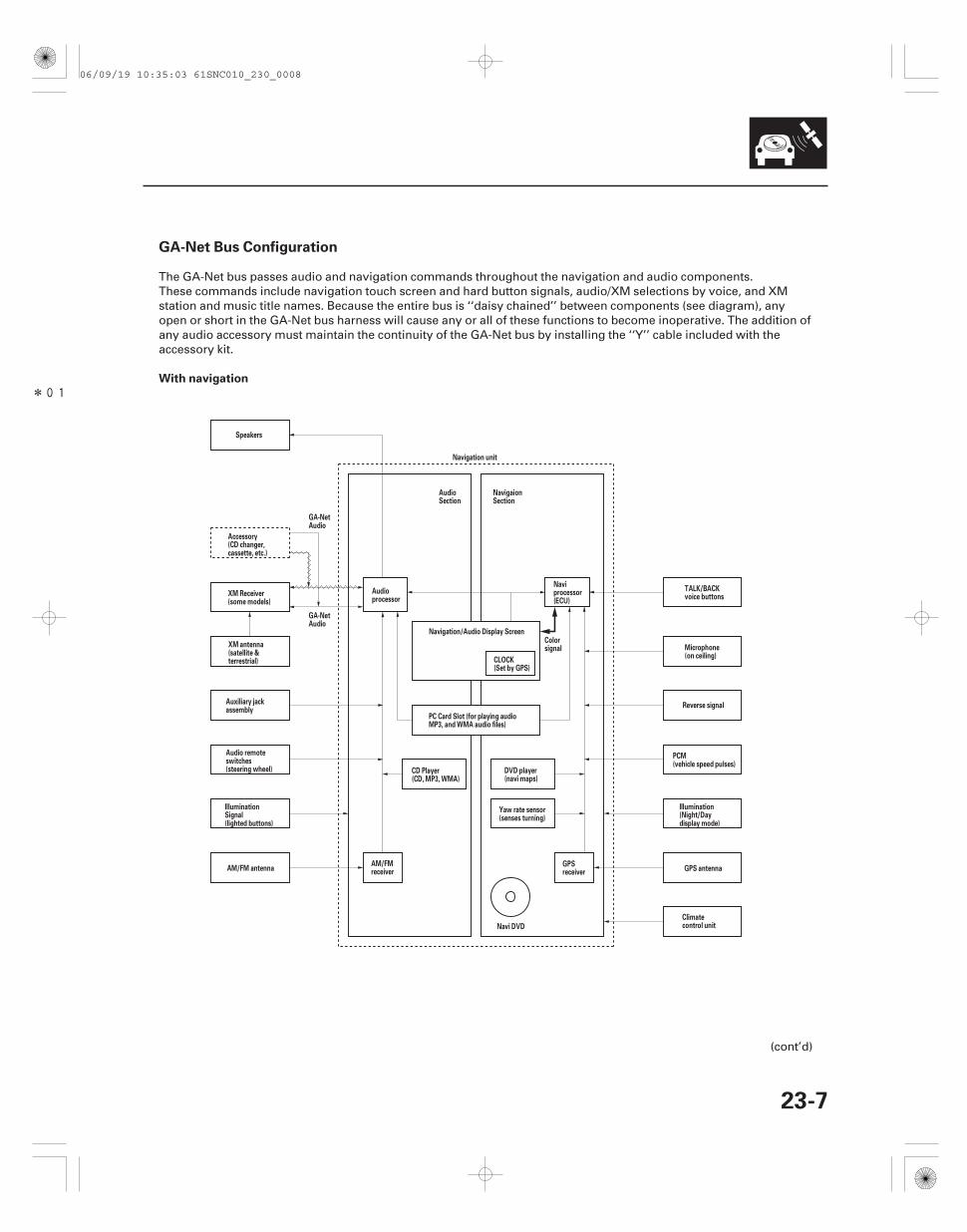
With navigation
23-7
Reverse signal
GPS antennaAM/FM antenna
Speakers
Navigation unit
Navi DVD
Navigation/Audio Display Screen
CLOCK(Set by GPS)
Colorsignal
Accessory(CD changer,cassette, etc.)
XM Receiver(some models)
XM antenna(satellite &terrestrial)
Auxiliary jackassembly
Audio remoteswitches(steering wheel)
IlluminationSignal(lighted buttons)
AM/FMreceiver
CD Player(CD, MP3, WMA)
Audioprocessor
PC Card Slot (for playing audioMP3, and WMA audio files)
Naviprocessor(ECU)
GPSreceiver
Yaw rate sensor(senses turning)
DVD player(navi maps)
GA-NetAudio
GA-NetAudio
AudioSection
NavigaionSection
Illumination(Night/Daydisplay mode)
PCM(vehicle speed pulses)
Microphone(on ceiling)
TALK/BACKvoice buttons
Climatecontrol unit
The GA-Net bus passes audio and navigation commands throughout the navigation and audio components.These commands include navigation touch screen and hard button signals, audio/XM selections by voice, and XMstation and music title names. Because the entire bus is ‘‘daisy chained’’ between components (see diagram), anyopen or short in the GA-Net bus harness will cause any or all of these functions to become inoperative. The addition ofany audio accessory must maintain the continuity of the GA-Net bus by installing the ‘‘Y’’ cable included with theaccessory kit.
(cont’d)
06/09/19 10:35:03 61SNC010_230_0008
-
Audio Glossary
Item Definition
23-8
Audio System
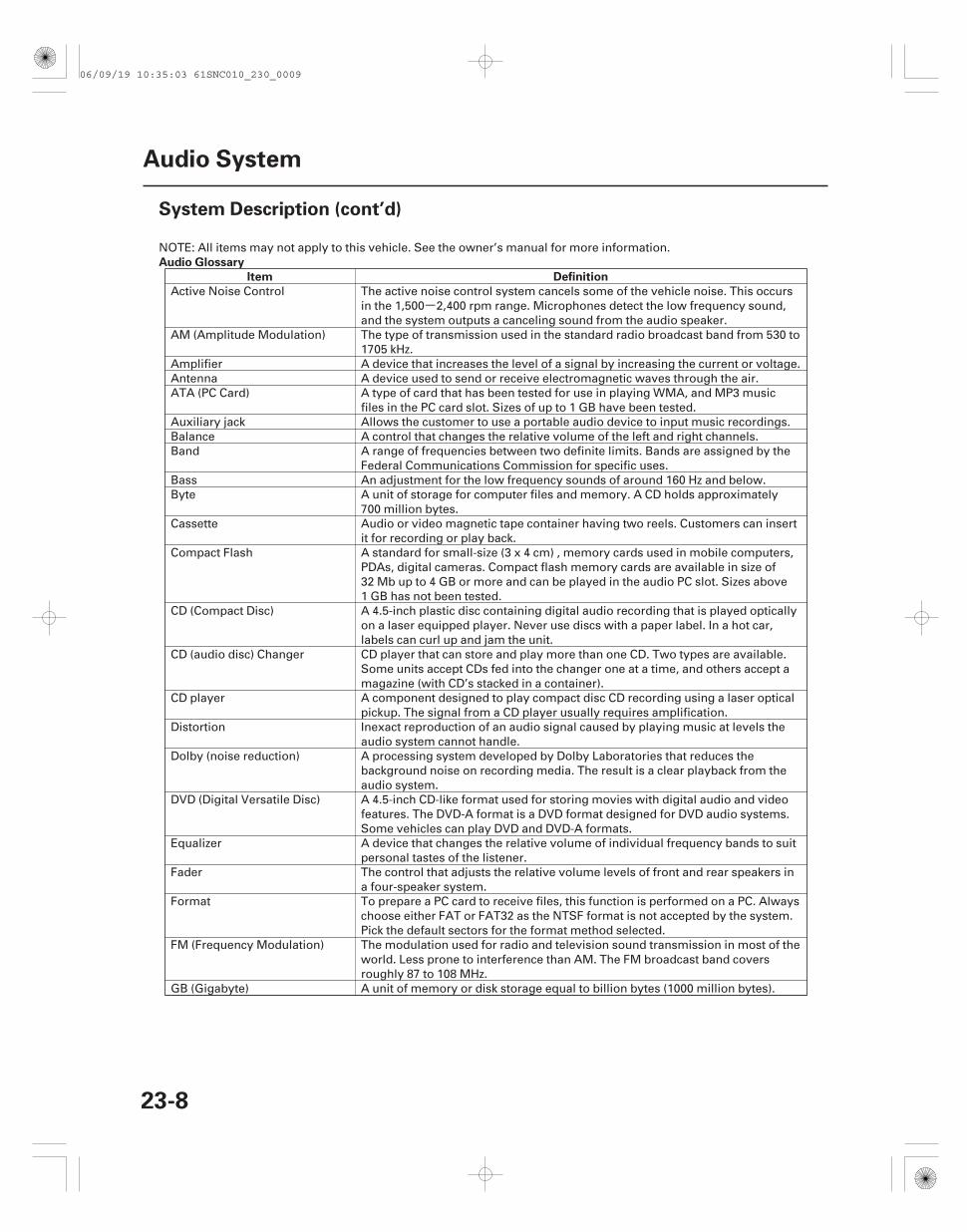
System Description (cont’d)
NOTE: All items may not apply to this vehicle. See the owner’s manual for more information.
Active Noise Control The active noise control system cancels some of the vehicle noise. This occursin the 1,500 2,400 rpm range. Microphones detect the low frequency sound,and the system outputs a canceling sound from the audio speaker.
AM (Amplitude Modulation) The type of transmission used in the standard radio broadcast band from 530 to1705 kHz.
Amplifier A device that increases the level of a signal by increasing the current or voltage.Antenna A device used to send or receive electromagnetic waves through the air.ATA (PC Card) A type of card that has been tested for use in playing WMA, and MP3 music
files in the PC card slot. Sizes of up to 1 GB have been tested.Auxiliary jack Allows the customer to use a portable audio device to input music recordings.Balance A control that changes the relative volume of the left and right channels.Band A range of frequencies between two definite limits. Bands are assigned by the
Federal Communications Commission for specific uses.Bass An adjustment for the low frequency sounds of around 160 Hz and below.Byte A unit of storage for computer files and memory. A CD holds approximately
700 million bytes.Cassette Audio or video magnetic tape container having two reels. Customers can insert
it for recording or play back.Compact Flash A standard for small-size (3 x 4 cm) , memory cards used in mobile computers,
PDAs, digital cameras. Compact flash memory cards are available in size of32 Mb up to 4 GB or more and can be played in the audio PC slot. Sizes above1 GB has not been tested.
CD (Compact Disc) A 4.5-inch plastic disc containing digital audio recording that is played opticallyon a laser equipped player. Never use discs with a paper label. In a hot car,labels can curl up and jam the unit.
CD (audio disc) Changer CD player that can store and play more than one CD. Two types are available.Some units accept CDs fed into the changer one at a time, and others accept amagazine (with CD’s stacked in a container).
CD player A component designed to play compact disc CD recording using a laser opticalpickup. The signal from a CD player usually requires amplification.
Distortion Inexact reproduction of an audio signal caused by playing music at levels theaudio system cannot handle.
Dolby (noise reduction) A processing system developed by Dolby Laboratories that reduces thebackground noise on recording media. The result is a clear playback from theaudio system.
DVD (Digital Versatile Disc) A 4.5-inch CD-like format used for storing movies with digital audio and videofeatures. The DVD-A format is a DVD format designed for DVD audio systems.Some vehicles can play DVD and DVD-A formats.
Equalizer A device that changes the relative volume of individual frequency bands to suitpersonal tastes of the listener.
Fader The control that adjusts the relative volume levels of front and rear speakers ina four-speaker system.
Format To prepare a PC card to receive files, this function is performed on a PC. Alwayschoose either FAT or FAT32 as the NTSF format is not accepted by the system.Pick the default sectors for the format method selected.
FM (Frequency Modulation) The modulation used for radio and television sound transmission in most of theworld. Less prone to interference than AM. The FM broadcast band coversroughly 87 to 108 MHz.
GB (Gigabyte) A unit of memory or disk storage equal to billion bytes (1000 million bytes).
06/09/19 10:35:03 61SNC010_230_0009
Audio Glossary
Item Definition
23-9
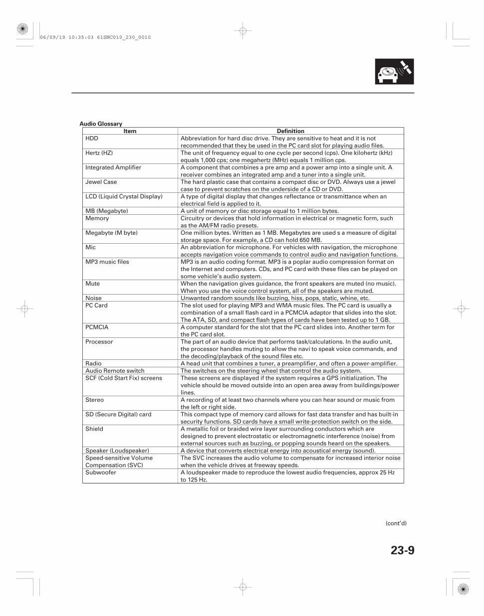
HDD Abbreviation for hard disc drive. They are sensitive to heat and it is notrecommended that they be used in the PC card slot for playing audio files.
Hertz (HZ) The unit of frequency equal to one cycle per second (cps). One kilohertz (kHz)equals 1,000 cps; one megahertz (MHz) equals 1 million cps.
Integrated Amplifier A component that combines a pre amp and a power amp into a single unit. Areceiver combines an integrated amp and a tuner into a single unit.
Jewel Case The hard plastic case that contains a compact disc or DVD. Always use a jewelcase to prevent scratches on the underside of a CD or DVD.
LCD (Liquid Crystal Display) A type of digital display that changes reflectance or transmittance when anelectrical field is applied to it.
MB (Megabyte) A unit of memory or disc storage equal to 1 million bytes.Memory Circuitry or devices that hold information in electrical or magnetic form, such
as the AM/FM radio presets.Megabyte (M byte) One million bytes. Written as 1 MB. Megabytes are used s a measure of digital
storage space. For example, a CD can hold 650 MB.Mic An abbreviation for microphone. For vehicles with navigation, the microphone
accepts navigation voice commands to control audio and navigation functions.MP3 music files MP3 is an audio coding format. MP3 is a poplar audio compression format on
the Internet and computers. CDs, and PC card with these files can be played onsome vehicle’s audio system.
Mute When the navigation gives guidance, the front speakers are muted (no music).When you use the voice control system, all of the speakers are muted.
Noise Unwanted random sounds like buzzing, hiss, pops, static, whine, etc.PC Card The slot used for playing MP3 and WMA music files. The PC card is usually a
combination of a small flash card in a PCMCIA adaptor that slides into the slot.The ATA, SD, and compact flash types of cards have been tested up to 1 GB.
PCMCIA A computer standard for the slot that the PC card slides into. Another term forthe PC card slot.
Processor The part of an audio device that performs task/calculations. In the audio unit,the processor handles muting to allow the navi to speak voice commands, andthe decoding/playback of the sound files etc.
Radio A head unit that combines a tuner, a preamplifier, and often a power-amplifier.Audio Remote switch The switches on the steering wheel that control the audio system.SCF (Cold Start Fix) screens These screens are displayed if the system requires a GPS initialization. The
vehicle should be moved outside into an open area away from buildings/powerlines.
Stereo A recording of at least two channels where you can hear sound or music fromthe left or right side.
SD (Secure Digital) card This compact type of memory card allows for fast data transfer and has built-insecurity functions. SD cards have a small write-protection switch on the side.
Shield A metallic foil or braided wire layer surrounding conductors which aredesigned to prevent electrostatic or electromagnetic interference (noise) fromexternal sources such as buzzing, or popping sounds heard on the speakers.
Speaker (Loudspeaker) A device that converts electrical energy into acoustical energy (sound).Speed-sensitive VolumeCompensation (SVC)
The SVC increases the audio volume to compensate for increased interior noisewhen the vehicle drives at freeway speeds.
Subwoofer A loudspeaker made to reproduce the lowest audio frequencies, approx 25 Hzto 125 Hz.
(cont’d)
06/09/19 10:35:03 61SNC010_230_0010
Audio Glossary
Item Definition
23-10
Audio System
System Description (cont’d)
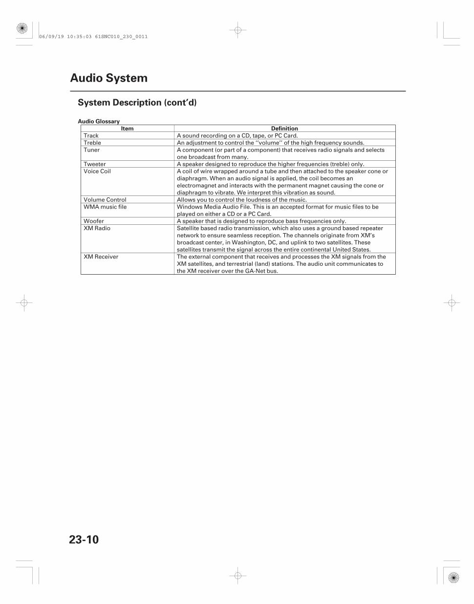
Track A sound recording on a CD, tape, or PC Card.Treble An adjustment to control the ‘‘volume’’ of the high frequency sounds.Tuner A component (or part of a component) that receives radio signals and selects
one broadcast from many.Tweeter A speaker designed to reproduce the higher frequencies (treble) only.Voice Coil A coil of wire wrapped around a tube and then attached to the speaker cone or
diaphragm. When an audio signal is applied, the coil becomes anelectromagnet and interacts with the permanent magnet causing the cone ordiaphragm to vibrate. We interpret this vibration as sound.
Volume Control Allows you to control the loudness of the music.WMA music file Windows Media Audio File. This is an accepted format for music files to be
played on either a CD or a PC Card.Woofer A speaker that is designed to reproduce bass frequencies only.XM Radio Satellite based radio transmission, which also uses a ground based repeater
network to ensure seamless reception. The channels originate from XM’sbroadcast center, in Washington, DC, and uplink to two satellites. Thesesatellites transmit the signal across the entire continental United States.
XM Receiver The external component that receives and processes the XM signals from theXM satellites, and terrestrial (land) stations. The audio unit communicates tothe XM receiver over the GA-Net bus.
06/09/19 10:35:03 61SNC010_230_0011
*02
04
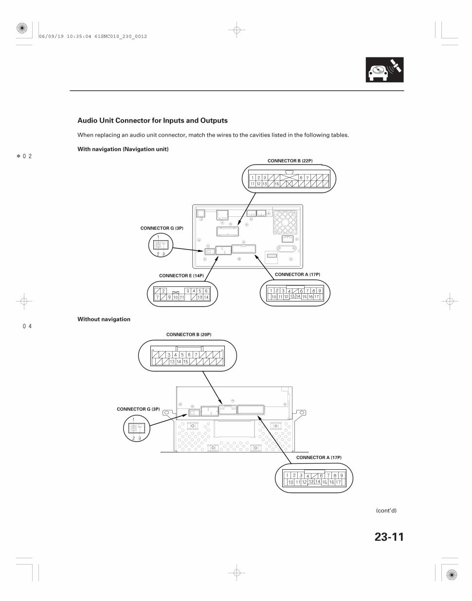
Audio Unit Connector for Inputs and Outputs
With navigation (Navigation unit)
Without navigation
23-11
CONNECTOR B (22P)
CONNECTOR G (3P)
CONNECTOR A (17P)CONNECTOR E (14P)
CONNECTOR G (3P)
CONNECTOR A (17P)
CONNECTOR B (20P)
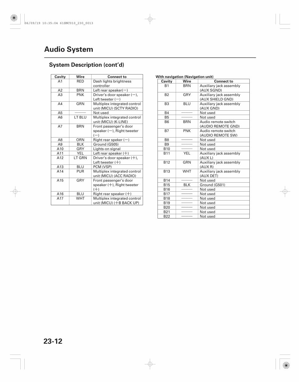
When replacing an audio unit connector, match the wires to the cavities listed in the following tables.
(cont’d)
06/09/19 10:35:04 61SNC010_230_0012
--
-
―――
--
-
++
+
++
+
+
――――――
―――――――――
―――
―――――――――――――――――――――
Cavity Wire Connect to With navigation (Navigation unit)
Cavity Wire Connect to
23-12
Audio System
System Description (cont’d)
A1 RED Dash lights brightnesscontroller
A2 BRN Left rear speaker( )A3 PNK Driver’s door speaker ( ),
Left tweeter ( )A4 GRN Multiplex integrated control
unit (MICU) (SCTY RADIO)A5 Not usedA6 LT BLU Multiplex integrated control
unit (MICU) (K-LINE)A7 BRN Front passenger’s door
speaker ( ), Right tweeter( )
A8 ORN Right rear speker ( )A9 BLK Ground (G505)A10 GRY Lights-on signalA11 YEL Left rear speaker ( )A12 LT GRN Driver’s door speaker ( ),
Left tweeter ( )A13 BLU PCM (VSP)A14 PUR Multiplex integrated control
unit (MICU) (ACC RADIO)A15 GRY Front passenger’s door
speaker ( ), Right tweeter( )
A16 BLU Right rear speaker ( )A17 WHT Multiplex integrated control
unit (MICU) ( B BACK UP)
B1 BRN Auxiliary jack assembly(AUX SGND)
B2 GRY Auxiliary jack assembly(AUX SHIELD GND)
B3 BLU Auxiliary jack assembly(AUX GND)
B4 Not usedB5 Not usedB6 BRN Audio remote switch
(AUDIO REMOTE GND)B7 PNK Audio remote switch
(AUDIO REMOTE SW)B8 Not usedB9 Not usedB10 Not usedB11 YEL Auxiliary jack assembly
(AUX L)B12 GRN Auxiliary jack assembly
(AUX R)B13 WHT Auxiliary jack assembly
(AUX DET)B14 Not usedB15 BLK Ground (G501)B16 Not usedB17 Not usedB18 Not usedB19 Not usedB20 Not usedB21 Not usedB22 Not used
06/09/19 10:35:04 61SNC010_230_0013
――――――
―――――――――――――――
―――――――――――――――
―――
++
+―――
+
-
―――--
――――――
―――+
――――――
―――+
Without navigation
Cavity Wire Connect to
With navigation
Cavity Wire Connect to
With navigation
Cavity Wire Connect to
Without navigation
Cavity Wire Connect to
23-13
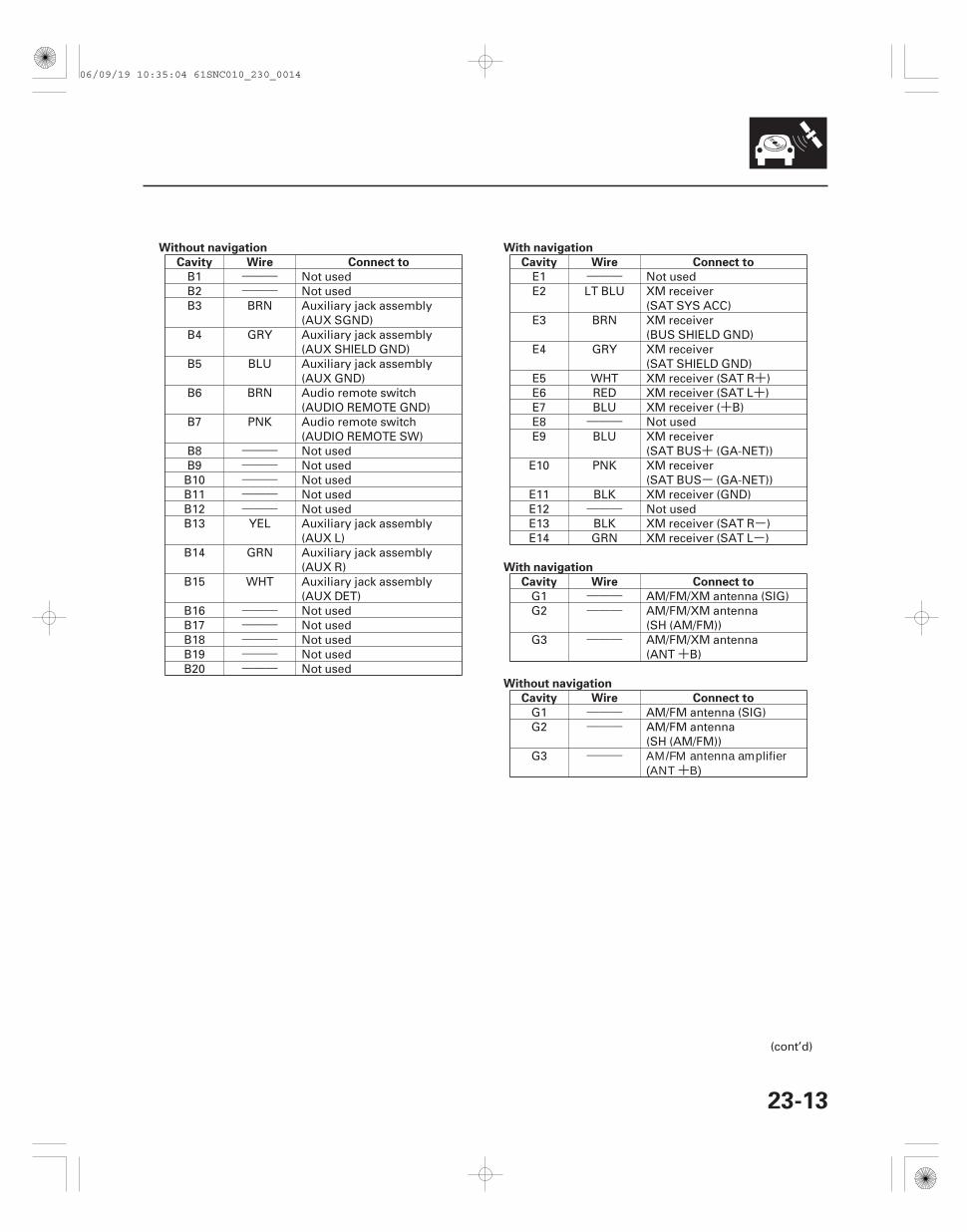
B1 Not usedB2 Not usedB3 BRN Auxiliary jack assembly
(AUX SGND)B4 GRY Auxiliary jack assembly
(AUX SHIELD GND)B5 BLU Auxiliary jack assembly
(AUX GND)B6 BRN Audio remote switch
(AUDIO REMOTE GND)B7 PNK Audio remote switch
(AUDIO REMOTE SW)B8 Not usedB9 Not usedB10 Not usedB11 Not usedB12 Not usedB13 YEL Auxiliary jack assembly
(AUX L)B14 GRN Auxiliary jack assembly
(AUX R)B15 WHT Auxiliary jack assembly
(AUX DET)B16 Not usedB17 Not usedB18 Not usedB19 Not usedB20 Not used
E1 Not usedE2 LT BLU XM receiver
(SAT SYS ACC)E3 BRN XM receiver
(BUS SHIELD GND)E4 GRY XM receiver
(SAT SHIELD GND)E5 WHT XM receiver (SAT R )E6 RED XM receiver (SAT L )E7 BLU XM receiver ( B)E8 Not usedE9 BLU XM receiver
(SAT BUS (GA-NET))E10 PNK XM receiver
(SAT BUS (GA-NET))E11 BLK XM receiver (GND)E12 Not usedE13 BLK XM receiver (SAT R )E14 GRN XM receiver (SAT L )
G1 AM/FM/XM antenna (SIG)G2 AM/FM/XM antenna
(SH (AM/FM))G3 AM/FM/XM antenna
(ANT B)
G1 AM/FM antenna (SIG)G2 AM/FM antenna
(SH (AM/FM))G3 AM/FM antenna amplifier
(ANT B)
(cont’d)
06/09/19 10:35:04 61SNC010_230_0014
+
―――++
――――――
+
-
―――--
――――――
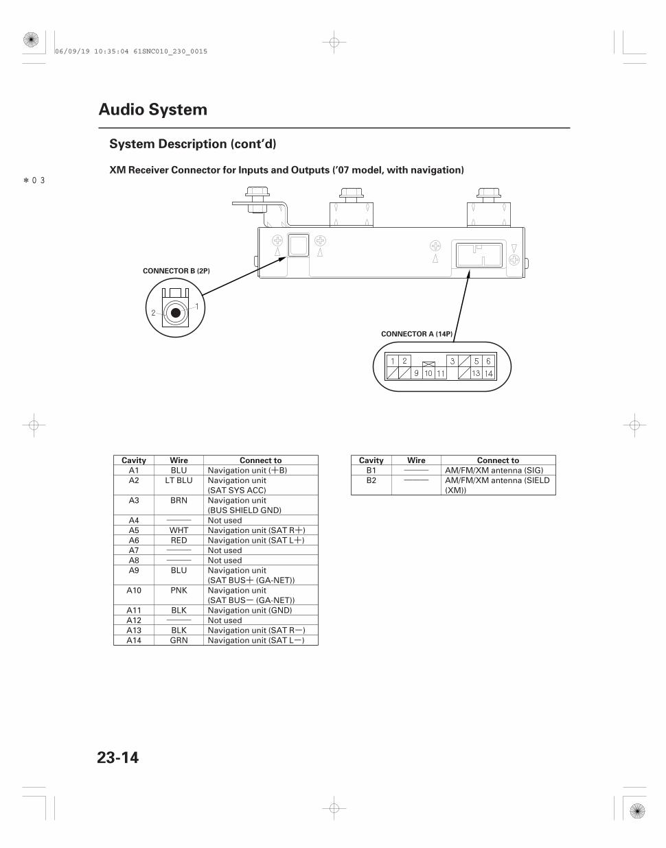
*03XM Receiver Connector for Inputs and Outputs (’07 model, with navigation)
Cavity Wire Connect to Cavity Wire Connect to
23-14
Audio System
System Description (cont’d)
CONNECTOR A (14P)
CONNECTOR B (2P)
A1 BLU Navigation unit ( B)A2 LT BLU Navigation unit
(SAT SYS ACC)A3 BRN Navigation unit
(BUS SHIELD GND)A4 Not usedA5 WHT Navigation unit (SAT R )A6 RED Navigation unit (SAT L )A7 Not usedA8 Not usedA9 BLU Navigation unit
(SAT BUS (GA-NET))A10 PNK Navigation unit
(SAT BUS (GA-NET))A11 BLK Navigation unit (GND)A12 Not usedA13 BLK Navigation unit (SAT R )A14 GRN Navigation unit (SAT L )
B1 AM/FM/XM antenna (SIG)B2 AM/FM/XM antenna (SIELD
(XM))
06/09/19 10:35:04 61SNC010_230_0015
05
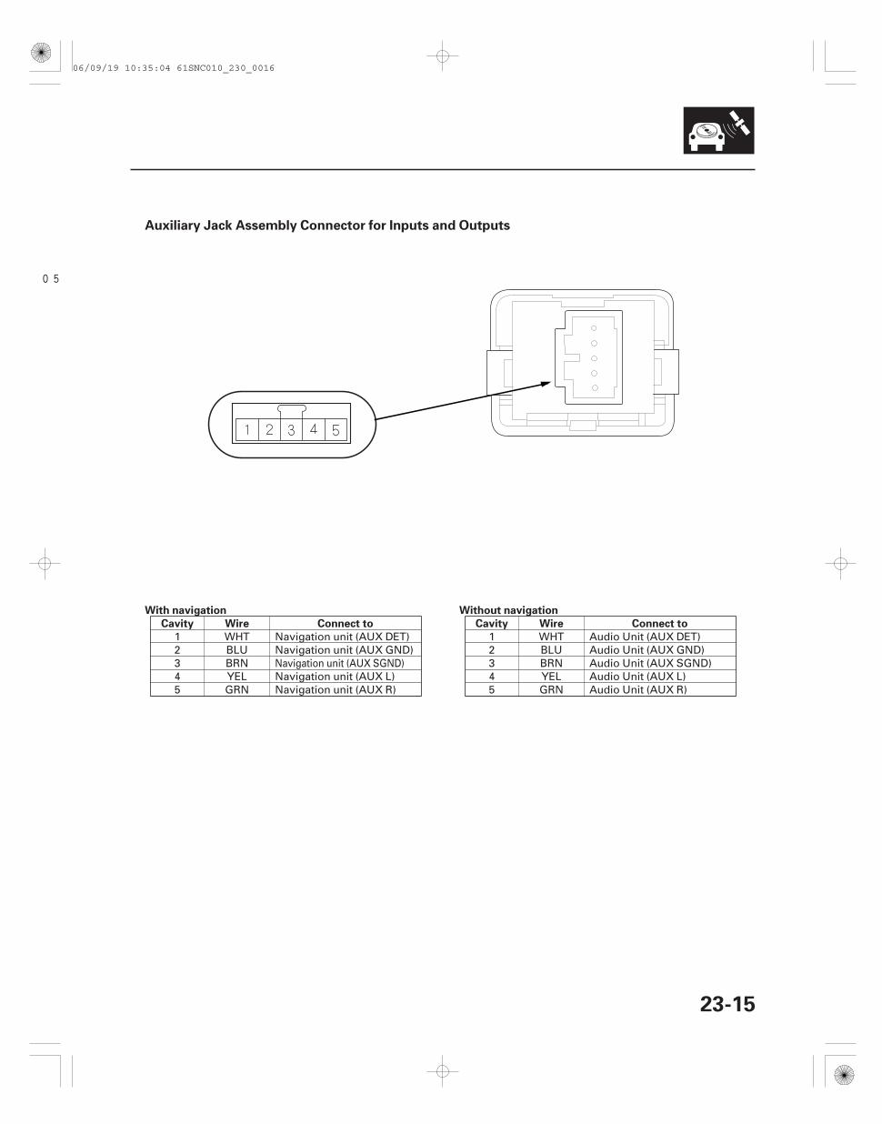
Auxiliary Jack Assembly Connector for Inputs and Outputs
With navigation
Cavity Wire Connect to
Without navigation
Cavity Wire Connect to
23-15
1 WHT Navigation unit (AUX DET)2 BLU Navigation unit (AUX GND)3 BRN4 YEL Navigation unit (AUX L)5 GRN Navigation unit (AUX R)
1 WHT Audio Unit (AUX DET)2 BLU Audio Unit (AUX GND)3 BRN Audio Unit (AUX SGND)4 YEL Audio Unit (AUX L)5 GRN Audio Unit (AUX R)
Navigation unit (AUX SGND)
06/09/19 10:35:04 61SNC010_230_0016
*90
SNC7AN1J10300000000EAAT80
- +
-
++ +
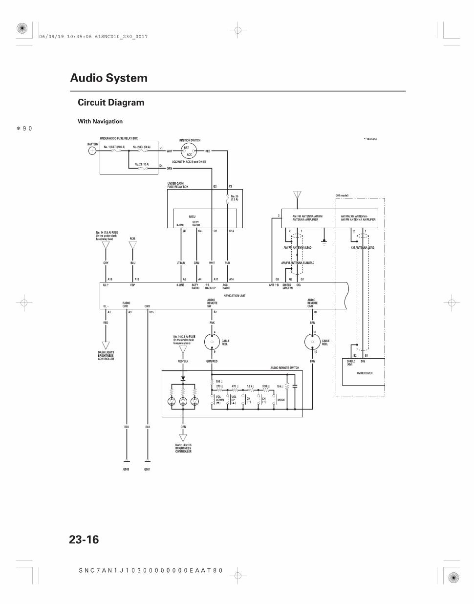
With Navigation
23-16
Audio System
Circuit Diagram
GND
G501
BLK
B15
RADIOSCTY
K-LINE
SHIELD(AM/FM)
SIG
3
G1G2
2 1
UNDER-HOOD FUSE/RELAY BOX
( ) ( )
AM/FM ANTENNA LEAD
AM/FM ANTENNA SUBLEAD
G3
ILL
A1
RED
RADIOACC
BACK UPBSCTY
RADIOK-LINE
Q8 Q4 Q1 Q14
LT BLU
A6 A4
GRN WHT
A17
VSP
PCM
BLU
A14
PUR
MICU
ACC HOT in ACC (I) and ON (II)
ORN
REDWHTACC
BAT
IGNITION SWITCH
No. 23 (10 A)
No. 2 (IG) (50 A)BATTERY
No. 1 (BAT) (100 A)
A10 A13
ILL
NAVIGATION UNIT
GRY
ANT B
10 k1.2 k470270
100
CH
(DOWNVOL VOL
UP(
MODE
BRN
B6
BRN
3.9 k
))
CH
RED/BLK GRN/RED
B7
PNK
GRN
SWREMOTEAUDIO AUDIO
REMOTEGND
9
4 3
10
AUDIO REMOTE SWITCH
BLK
G505
GNDRADIO
A9
No. 35(7.5 A)
No. 14 (7.5 A) FUSE(In the under-dashfuse/relay box)
DASH LIGHTSBRIGHTNESSCONTROLLER
AM/FM ANTENNA-AM/FMANTENNA AMPLIFIER
No. 14 (7.5 A) FUSE(In the under-dashfuse/relay box)
CABLEREEL
CABLEREEL
DASH LIGHTSBRIGHTNESSCONTROLLER
UNDER-DASHFUSE/RELAY BOX
2 1
XM ANTENNA LEAD
SHIELD(XM)
SIG
B1B2
XM RECEIVER
(’07 model)
AM/FM/XM ANTENNA-AM/FM ANTENNA AMPLIFIER
*: ’06 model
H1
D4
G2 C2
06/09/19 10:35:06 61SNC010_230_0017
*90
-++ -+ --+
-
-
+
+
-
--+
+
+
+
+-+
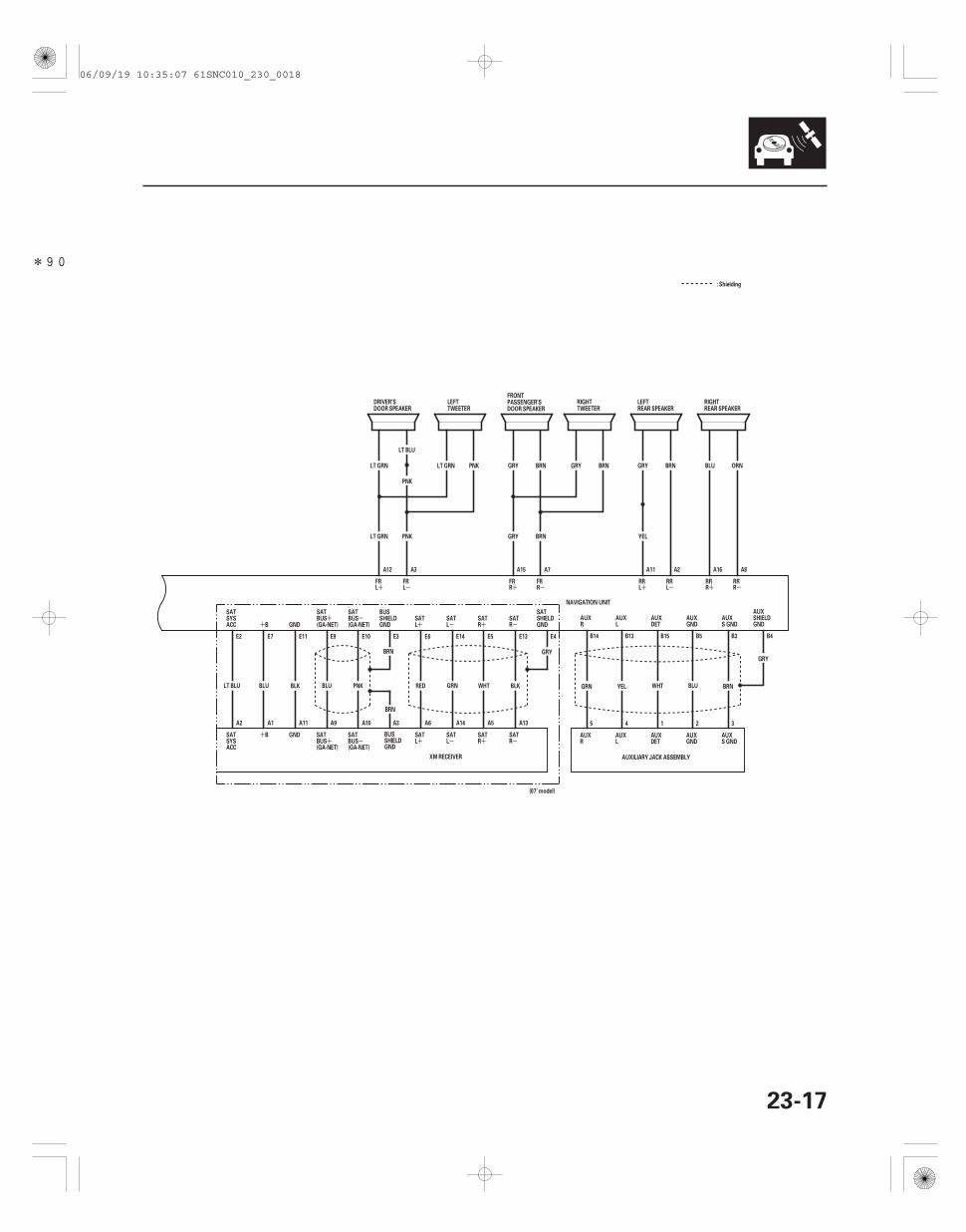
23-17
B4B3B5B15B13B14
LT BLU
32145
AUXILIARY JACK ASSEMBLY
RAUX
LAUX AUX
DET S GNDAUXAUX
GND
AUX
GNDSHIELD
GRY
GNDAUX AUX
S GND
BLU BRN
DETAUX
WHT
AUXL
YEL
AUXR
GRN
RRRRR
RLRR RR
LRFR FR
RLFR
YEL
PNK
PNKLT GRN LT GRN
PNKLT GRN
GRY
GRY
GRY BRNBRN
BRN
A8A16A11 A2
BRNGRY
A7A15A12 A3
BLU ORN
FRL
NAVIGATION UNIT
: Shielding
DRIVER’SDOOR SPEAKER
LEFTTWEETER
FRONTPASSENGER’SDOOR SPEAKER
LEFTREAR SPEAKER
RIGHTTWEETER
RIGHTREAR SPEAKER
GND
(GA-NET)GND
A13
RSAT
SATR
E13
SATR
A5
E5
RSAT
A14
LSAT
SATL
E14
GNDSHIELDBUS
E3
SATBUS
A10
E10
(GA-NET)BUSSAT
E9
A9A11
E11E7
B
B
A1A2
ACC
SAT
SYSSAT
SYSACC
E2
SAT
E6
LSAT
E4
SHIELDGND
SATL
A6
BRN
PNKBLUBLKBLULT BLU RED GRN BLKWHT
GRY
XM RECEIVER
A3
BRN
GNDSHIELDBUS
(GA-NET)
SATBUS
(GA-NET)BUSSAT
(07’ model)
06/09/19 10:35:07 61SNC010_230_0018
*91
SNC7AN0J10300000000EAAT80
- +
-
++ +
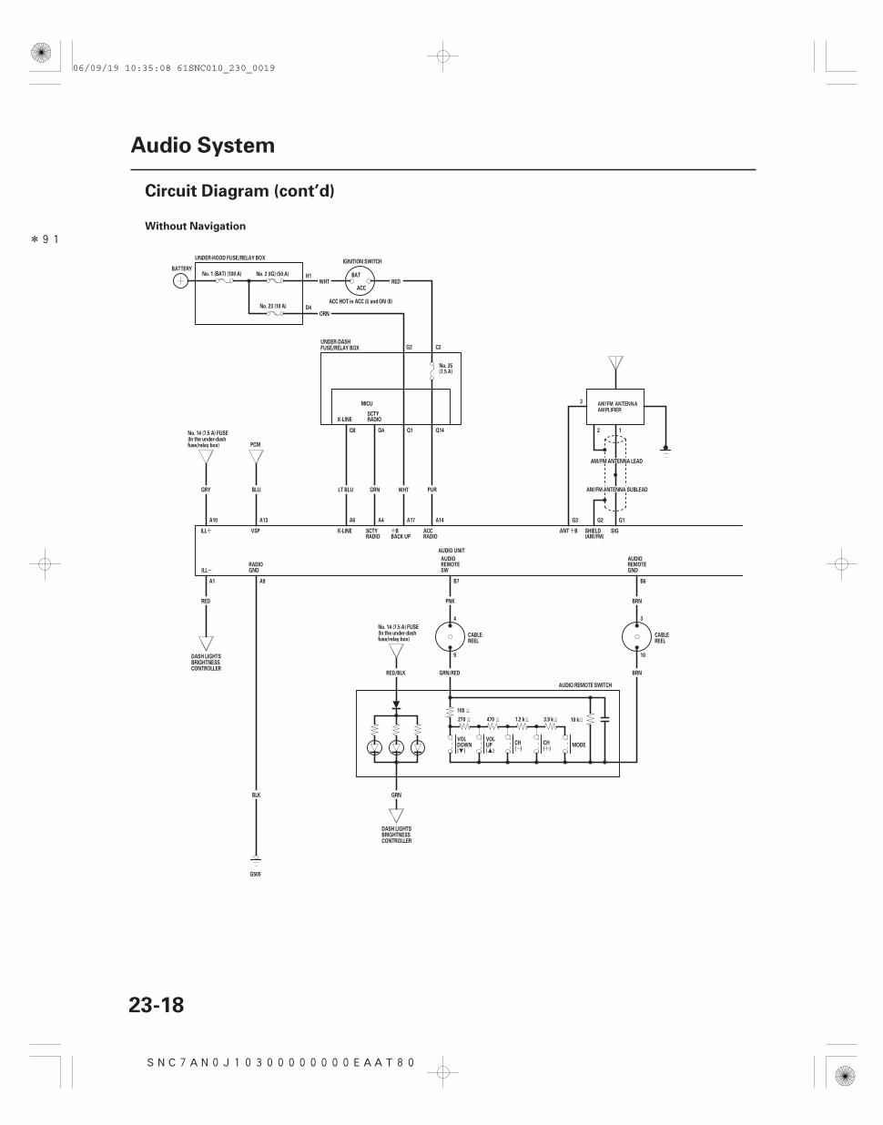
Without Navigation
23-18
Audio System
Circuit Diagram (cont’d)
RADIOSCTY
K-LINE
SHIELD(AM/FM)
SIG
3
G1G2
2 1
UNDER-HOOD FUSE/RELAY BOX
( ) ( )
AM/FM ANTENNA LEAD
AM/FM ANTENNA SUBLEAD
G3
ILL
A1
RED
RADIOACC
BACK UPBSCTY
RADIOK-LINE
Q8 Q4 Q1 Q14
LT BLU
A6 A4
GRN WHT
A17
VSP
PCM
BLU
A14
PUR
MICU
ACC HOT in ACC (I) and ON (II)
ORN
REDWHTACC
BAT
IGNITION SWITCH
No. 23 (10 A)
No. 2 (IG) (50 A)BATTERY
No. 1 (BAT) (100 A)
A10 A13
ILL
AUDIO UNIT
GRY
ANT B
10 k1.2 k470270
100
CH
(DOWNVOL VOL
UP(
MODE
BRN
B6
BRN
3.9 k
))
CH
RED/BLK GRN/RED
B7
PNK
GRN
SWREMOTEAUDIO AUDIO
REMOTEGND
9
4 3
10
AUDIO REMOTE SWITCH
BLK
G505
GNDRADIO
A9
No. 35(7.5 A)
No. 14 (7.5 A) FUSE(In the under-dashfuse/relay box)
DASH LIGHTSBRIGHTNESSCONTROLLER
AM/FM ANTENNAAMPLIFIER
No. 14 (7.5 A) FUSE(In the under-dashfuse/relay box)
CABLEREEL
CABLEREEL
DASH LIGHTSBRIGHTNESSCONTROLLER
UNDER-DASHFUSE/RELAY BOX
H1
D4
G2 C2
06/09/19 10:35:08 61SNC010_230_0019
*91
-++ -+ --+
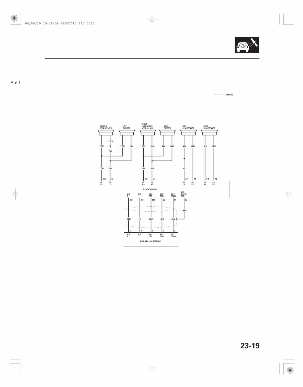
23-19
B2B1B3B13B11B12
LT BLU
32145
AUXILIARY JACK ASSEMBLY
RAUX
LAUX AUX
DET SGNDAUXAUX
GND
AUX
GNDSHIELD
GRY
GNDAUX AUX
SGND
BLU BRN
DETAUX
WHT
AUXL
YEL
AUXR
GRN
RRRRR
RLRR RR
LRFR FR
RLFR
YEL
PNK
PNKLT GRN LT GRN
PNKLT GRN
GRY
GRY
GRY BRNBRN
BRN
A8A16A11 A2
BRNGRY
A7A15A12 A3
BLU ORN
FRL
NAVIGATION UNIT
: Shielding
DRIVER’SDOOR SPEAKER
LEFTTWEETER
FRONTPASSENGER’SDOOR SPEAKER
LEFTREAR SPEAKER
RIGHTTWEETER
RIGHTREAR SPEAKER
06/09/19 10:35:09 61SNC010_230_0020
01
SNC7AN0J10300000000BBAT00
Without Navigation
How to check for audio system condition
‘‘No. 3’’ button
‘‘No. 4’’ button
‘‘No. 5’’ button
‘‘FM’’ button (Push and hold 5 sec.)
‘‘CD’’ button (Push and hold 5 sec.)
23-20
Audio System
Self-diagnostic Function
A
The audio system has a self-diagnostic function. To run the self-diagnostic function, do the following:
NOTE: The audio unit must be in the code enter screen before doing the self-diagnostic function.
1. Turn the ignition switch to the ACC (I) or ON (II) position.
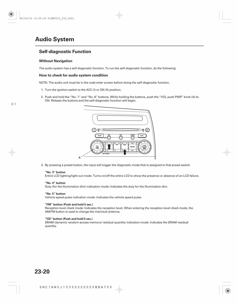
2. Push and hold the ‘‘No. 1’’ and ‘‘No. 6’’ buttons. While holding the buttons, push the ‘‘VOL push PWR’’ knob (A) toON. Release the buttons and the self-diagnostic function will begin.
3. By pressing a preset button, the input will trigger the diagnostic mode that is assigned to that preset switch.
Entire LCD lighting/light-out mode: Turns on/off the entire LCD to show the presence or absence of an LCD failure.
Duty (for the Illumination dim) indication mode: Indicates the duty for the Illumination dim.
Vehicle speed pulse indication mode: Indicates the vehicle speed pulse.
Reception level check mode: Indicates the reception level. When entering the reception level check mode, theAM/FM button is used to change the main/sub antenna.
DRAM (dynamic random-access memory) residual quantity indication mode: Indicates the DRAM residualquantity.
06/09/19 10:35:09 61SNC010_230_0021
02Display Specifications
Speaker check mode
23-21
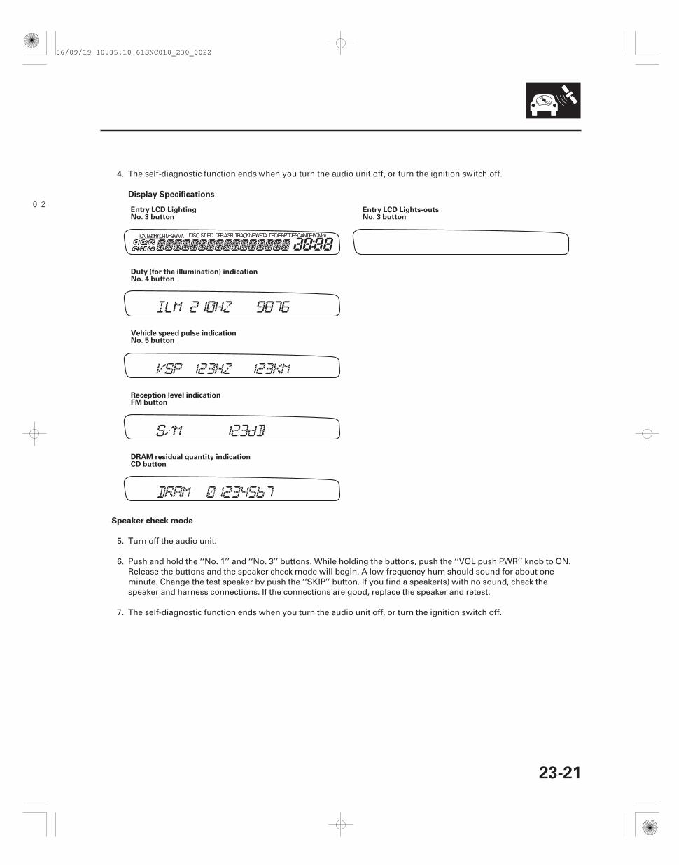
Entry LCD LightingNo. 3 button
Entry LCD Lights-outsNo. 3 button
Duty (for the illumination) indicationNo. 4 button
Vehicle speed pulse indicationNo. 5 button
Reception level indicationFM button
DRAM residual quantity indicationCD button
4. The self-diagnostic function ends when you turn the audio unit off, or turn the ignition switch off.
5. Turn off the audio unit.
6. Push and hold the ‘‘No. 1’’ and ‘‘No. 3’’ buttons. While holding the buttons, push the ‘‘VOL push PWR’’ knob to ON.Release the buttons and the speaker check mode will begin. A low-frequency hum should sound for about oneminute. Change the test speaker by push the ‘‘SKIP’’ button. If you find a speaker(s) with no sound, check thespeaker and harness connections. If the connections are good, replace the speaker and retest.
7. The self-diagnostic function ends when you turn the audio unit off, or turn the ignition switch off.
06/09/19 10:35:10 61SNC010_230_0022
--
---
-
SNC7A00J10300000000BBAT11
Error Code Displayed Possible Cause Solution
23-22
Audio System
Error Codes
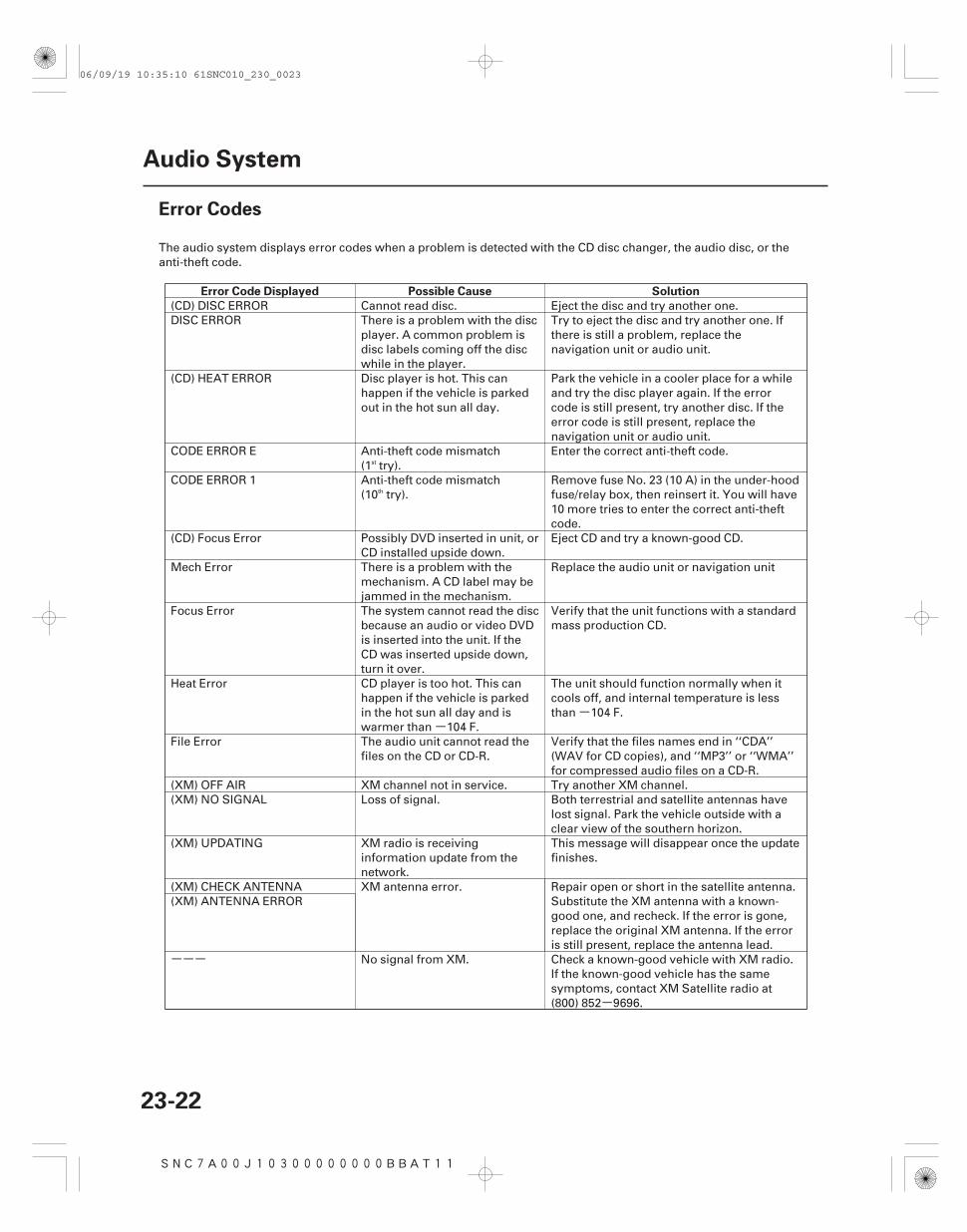
The audio system displays error codes when a problem is detected with the CD disc changer, the audio disc, or theanti-theft code.
(CD) DISC ERROR Cannot read disc. Eject the disc and try another one.DISC ERROR There is a problem with the disc
player. A common problem isdisc labels coming off the discwhile in the player.
Try to eject the disc and try another one. Ifthere is still a problem, replace thenavigation unit or audio unit.
(CD) HEAT ERROR Disc player is hot. This canhappen if the vehicle is parkedout in the hot sun all day.
Park the vehicle in a cooler place for a whileand try the disc player again. If the errorcode is still present, try another disc. If theerror code is still present, replace thenavigation unit or audio unit.
CODE ERROR E Anti-theft code mismatch(1 try).
Enter the correct anti-theft code.
CODE ERROR 1 Anti-theft code mismatch(10 try).
Remove fuse No. 23 (10 A) in the under-hoodfuse/relay box, then reinsert it. You will have10 more tries to enter the correct anti-theftcode.
(CD) Focus Error Possibly DVD inserted in unit, orCD installed upside down.
Eject CD and try a known-good CD.
Mech Error There is a problem with themechanism. A CD label may bejammed in the mechanism.
Replace the audio unit or navigation unit
Focus Error The system cannot read the discbecause an audio or video DVDis inserted into the unit. If theCD was inserted upside down,turn it over.
Verify that the unit functions with a standardmass production CD.
Heat Error CD player is too hot. This canhappen if the vehicle is parkedin the hot sun all day and iswarmer than 104 F.
The unit should function normally when itcools off, and internal temperature is lessthan 104 F.
File Error The audio unit cannot read thefiles on the CD or CD-R.
Verify that the files names end in ‘‘CDA’’(WAV for CD copies), and ‘‘MP3’’ or ‘‘WMA’’for compressed audio files on a CD-R.
(XM) OFF AIR XM channel not in service. Try another XM channel.(XM) NO SIGNAL Loss of signal. Both terrestrial and satellite antennas have
lost signal. Park the vehicle outside with aclear view of the southern horizon.
(XM) UPDATING XM radio is receivinginformation update from thenetwork.
This message will disappear once the updatefinishes.
(XM) CHECK ANTENNA XM antenna error. Repair open or short in the satellite antenna.Substitute the XM antenna with a known-good one, and recheck. If the error is gone,replace the original XM antenna. If the erroris still present, replace the antenna lead.
(XM) ANTENNA ERROR
No signal from XM. Check a known-good vehicle with XM radio.If the known-good vehicle has the samesymptoms, contact XM Satellite radio at(800) 852 9696.
st
th
06/09/19 10:35:10 61SNC010_230_0023
*01
SNC7AN1J10300000000FAAT01
-
-
-
-
-
-
-
-
-
-
Poor AM or FM radio reception orinterference (with navigation)
YES
NO
YES
NO
YES
NO
YES
NO
YES
NO
23-23
Symptom Troubleshooting
AM/FM/XM ANTENNA 3P CONNECTORor AM/FM ANTENNA 3P CONNECTOR
NOTE: Check the radio reception in an open area.Compare it to a known-good vehicle whenever possible.Poor reception/interference can be caused by thefollowing:• The radio station is far away.• Atmospheric conditions are unfavorable.• Tall buildings, mountains, or high-voltage power
lines are nearby.• Aftermarket window tinting or electronic accessories.
1. Do the seek stop test (see page 23-58).
Multipath interference or weak station.Operation is normal.
Go to step 2.
2. Check if the radio reception/interference is thesame in several locations.
Go to step 3.
Multipath interference or weak station.Operation is normal.
3. Check the reception/interference while the engineis running.
Check the antenna and radio grounds. If OK,check the charging system and the ignitionsystem.
Go to step 4.
4. Check the AM/FM/XM antenna or AM/FM antennamast for cracks or other damage. Verify that theAM/FM/XM antenna or AM/FM antenna mast is notloose.
NOTE: Do not use any tools to tighten the AM/FM/XM antenna or AM/FM antenna mast.
• Replace the AM/FM/XM antenna mast (see page23-64) (’07 model).
• Replace the AM/FM antenna mast (see page23-64) (’06 model).
Go to step 5.
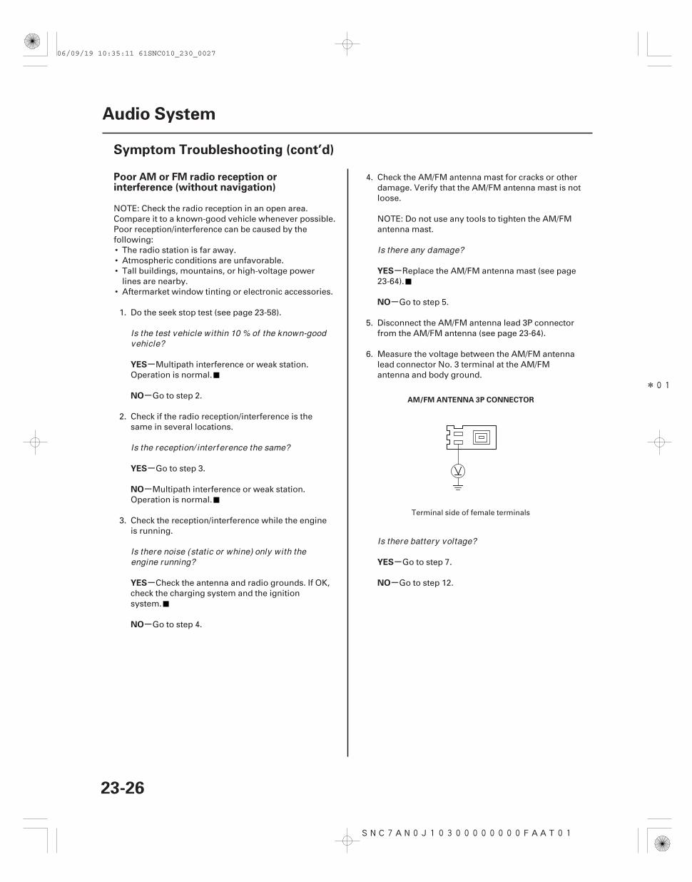
5. Disconnect the AM/FM antenna lead 3P connectorfrom the AM/FM/XM antenna or AM/FM antenna(see page 23-64).
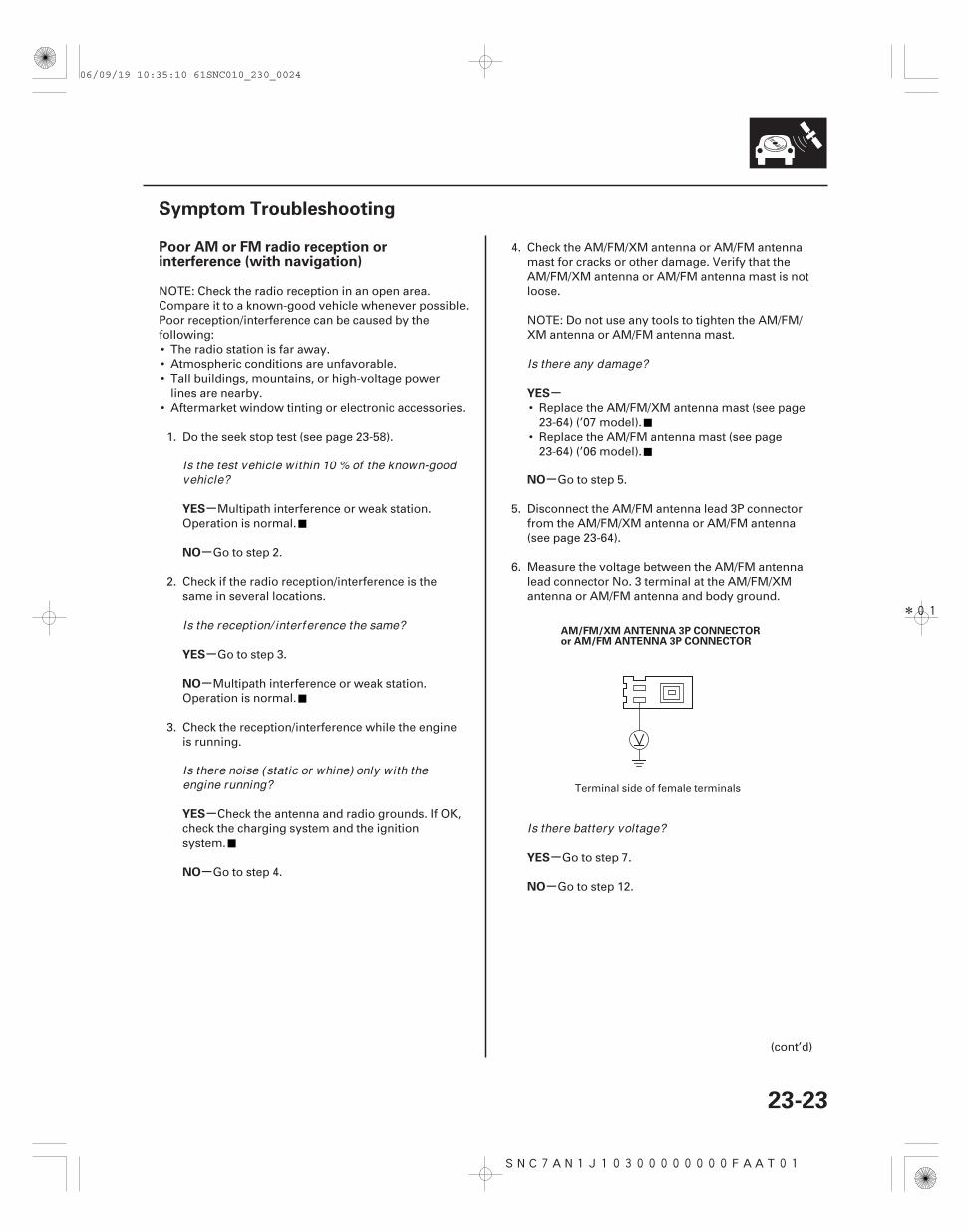
6. Measure the voltage between the AM/FM antennalead connector No. 3 terminal at the AM/FM/XMantenna or AM/FM antenna and body ground.
Go to step 7.
Go to step 12.
(cont’d)
Terminal side of female terminals
Is the test vehicle within 10 % of the known-goodvehicle?
Is the reception/ interference the same?
Is there noise (static or whine) only with theengine running?
Is there any damage?
Is there battery voltage?
06/09/19 10:35:10 61SNC010_230_0024
*02
03
-
-
-
-
YES
NO
YES
NO
23-24
Audio System
Symptom Troubleshooting (cont’d)
NAVIGATION UNIT CONNECTOR G (3P)
AM/FM/XM ANTENNA 3P CONNECTORor AM/FM ANTENNA 3P CONNECTOR
NAVIGATION UNIT CONNECTOR G (3P)
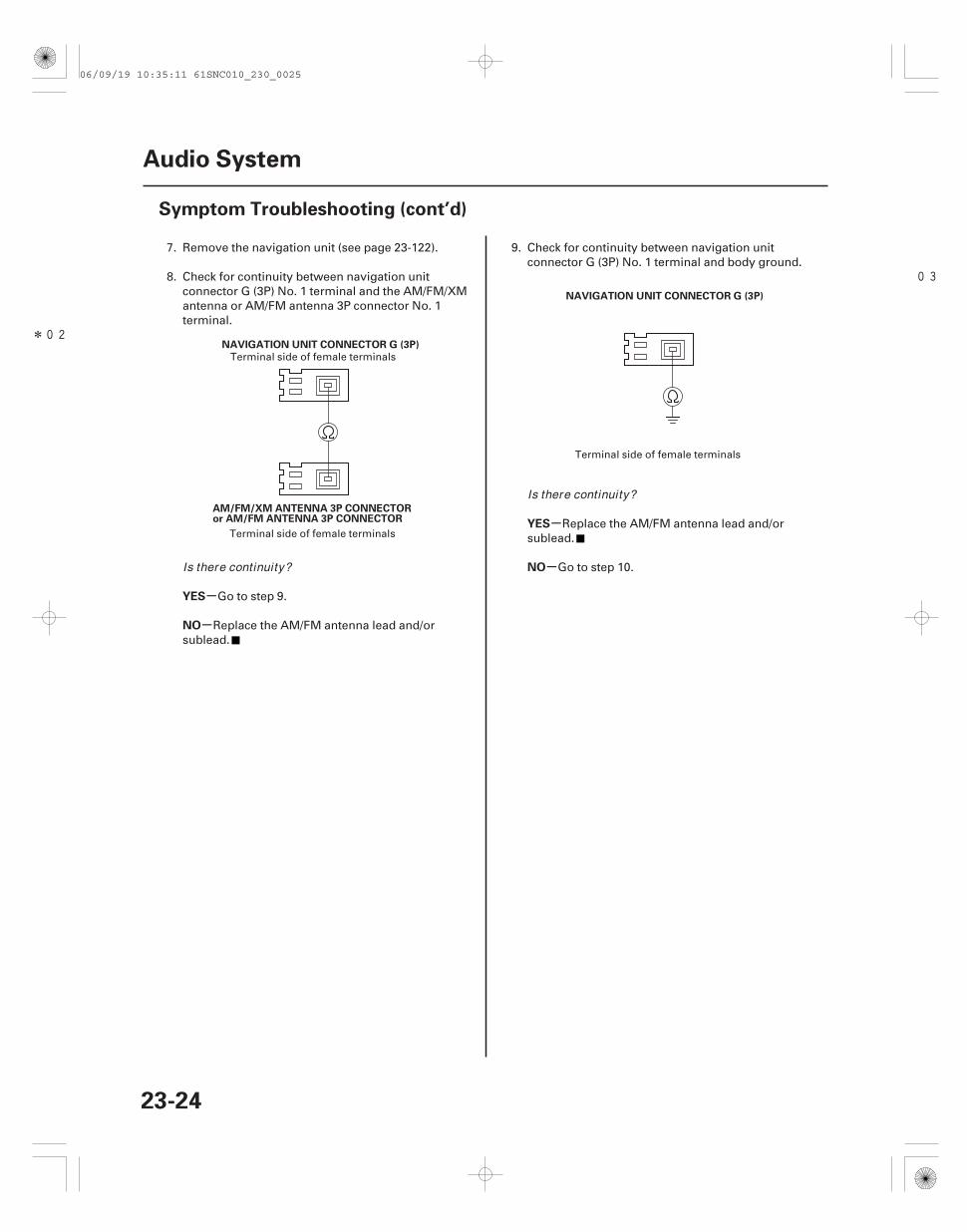
7. Remove the navigation unit (see page 23-122).
8. Check for continuity between navigation unitconnector G (3P) No. 1 terminal and the AM/FM/XMantenna or AM/FM antenna 3P connector No. 1terminal.
Go to step 9.
Replace the AM/FM antenna lead and/orsublead.
9. Check for continuity between navigation unitconnector G (3P) No. 1 terminal and body ground.
Replace the AM/FM antenna lead and/orsublead.
Go to step 10.
Terminal side of female terminals
Terminal side of female terminals
Terminal side of female terminals
Is there continuity?
Is there continuity?
06/09/19 10:35:11 61SNC010_230_0025
*03
05
*04
*05
-
-
-
-
-
-
-
-
YES
NO
YES
NO
YES
NO
YES
NO
23-25
NAVIGATION UNIT CONNECTOR G (3P)
AM/FM/XM ANTENNA 3P CONNECTORor AM/FM ANTENNA 3P CONNECTOR
NAVIGATION UNIT CONNECTOR G (3P)
NAVIGATION UNIT CONNECTOR G (3P)
AM/FM/XM ANTENNA 3P CONNECTORor AM/FM ANTENNA 3P CONNECTOR
AM/FM/XM ANTENNA 3P CONNECTORor AM/FM ANTENNA 3P CONNECTOR
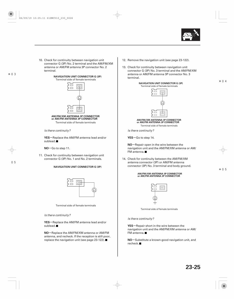
10. Check for continuity between navigation unitconnector G (3P) No. 2 terminal and the AM/FM/XMantenna or AM/FM antenna 3P connector No. 2terminal.
Replace the AM/FM antenna lead and/orsublead.
Go to step 11.
11. Check for continuity between navigation unitconnector G (3P) No. 1 and No. 2 terminals.
Replace the AM/FM antenna lead and/orsublead.
Replace the AM/FM/XM antenna or AM/FMantenna, and recheck. If the reception is still poor,replace the navigation unit (see page 23-122).
12. Remove the navigation unit (see page 23-122).
13. Check for continuity between navigation unitconnector G (3P) No. 3 terminal and the AM/FM/XMantenna or AM/FM antenna 3P connector No. 3terminal.
Go to step 14.
Repair open in the wire between thenavigation unit and the AM/FM/XM antenna or AM/FM antenna.
14. Check for continuity between the AM/FM/XMantenna connector (3P) or AM/FM antennaconnector (3P) No. 3 terminal and body ground.
Repair short in the wire between thenavigation unit and the AM/FM/XM antenna or AM/FM antenna.
Substitute a known-good navigation unit, andrecheck.
Terminal side of female terminals
Terminal side of female terminals
Terminal side of female terminals
Terminal side of female terminals
Terminal side of female terminals
Terminal side of female terminals
Is there continuity?
Is there continuity?
Is there continuity?
Is there continuity?
06/09/19 10:35:11 61SNC010_230_0026
*01
SNC7AN0J10300000000FAAT01
-
-
-
-
-
-
-
-
-
-
Poor AM or FM radio reception orinterference (without navigation)
YES
NO
YES
NO
YES
NO
YES
NO
YES
NO
23-26
Audio System
Symptom Troubleshooting (cont’d)
AM/FM ANTENNA 3P CONNECTOR
NOTE: Check the radio reception in an open area.Compare it to a known-good vehicle whenever possible.Poor reception/interference can be caused by thefollowing:• The radio station is far away.• Atmospheric conditions are unfavorable.• Tall buildings, mountains, or high-voltage power
lines are nearby.• Aftermarket window tinting or electronic accessories.
1. Do the seek stop test (see page 23-58).
Multipath interference or weak station.Operation is normal.
Go to step 2.
2. Check if the radio reception/interference is thesame in several locations.
Go to step 3.
Multipath interference or weak station.Operation is normal.
3. Check the reception/interference while the engineis running.
Check the antenna and radio grounds. If OK,check the charging system and the ignitionsystem.
Go to step 4.
4. Check the AM/FM antenna mast for cracks or otherdamage. Verify that the AM/FM antenna mast is notloose.
NOTE: Do not use any tools to tighten the AM/FMantenna mast.
Replace the AM/FM antenna mast (see page23-64).
Go to step 5.
5. Disconnect the AM/FM antenna lead 3P connectorfrom the AM/FM antenna (see page 23-64).
6. Measure the voltage between the AM/FM antennalead connector No. 3 terminal at the AM/FMantenna and body ground.
Go to step 7.
Go to step 12.
Terminal side of female terminals
Is the test vehicle within 10 % of the known-goodvehicle?
Is the reception/ interference the same?
Is there noise (static or whine) only with theengine running?
Is there any damage?
Is there battery voltage?
06/09/19 10:35:11 61SNC010_230_0027
*02
03
-
-
-
-YES
NO
YES
NO
23-27
AUDIO UNIT CONNECTOR G (3P)
AM/FM ANTENNA 3P CONNECTOR
AUDIO UNIT CONNECTOR G (3P)
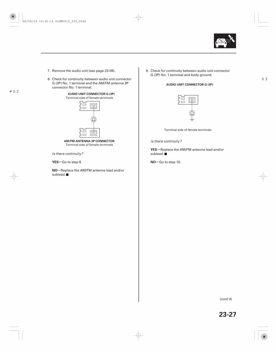
7. Remove the audio unit (see page 23-59).
8. Check for continuity between audio unit connectorG (3P) No. 1 terminal and the AM/FM antenna 3Pconnector No. 1 terminal.
Go to step 9.
Replace the AM/FM antenna lead and/orsublead.
9. Check for continuity between audio unit connectorG (3P) No. 1 terminal and body ground.
Replace the AM/FM antenna lead and/orsublead.
Go to step 10.
(cont’d)
Terminal side of female terminals
Terminal side of female terminals
Terminal side of female terminals
Is there continuity?
Is there continuity?
06/09/19 10:35:12 61SNC010_230_0028
*03
05
*04
*06
-
-
-
-
-
-
-
-
YES
NO
YES
NO
YES
NO
YES
NO
23-28
Audio System
Symptom Troubleshooting (cont’d)
AUDIO UNIT CONNECTOR G (3P)
AM/FM ANTENNA 3P CONNECTOR
AUDIO UNIT CONNECTOR G (3P)
AUDIO UNIT CONNECTOR G (3P)
AM/FM ANTENNA 3P CONNECTOR
AM/FM ANTENNA 3P CONNECTOR
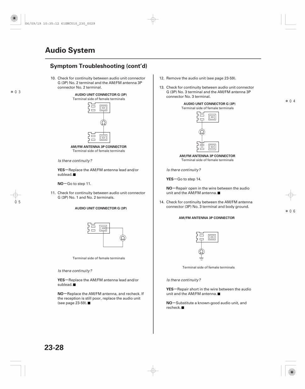
10. Check for continuity between audio unit connectorG (3P) No. 2 terminal and the AM/FM antenna 3Pconnector No. 2 terminal.
Replace the AM/FM antenna lead and/orsublead.
Go to step 11.
11. Check for continuity between audio unit connectorG (3P) No. 1 and No. 2 terminals.
Replace the AM/FM antenna lead and/orsublead.
Replace the AM/FM antenna, and recheck. Ifthe reception is still poor, replace the audio unit(see page 23-59).
12. Remove the audio unit (see page 23-59).
13. Check for continuity between audio unit connectorG (3P) No. 3 terminal and the AM/FM antenna 3Pconnector No. 3 terminal.
Go to step 14.
Repair open in the wire between the audiounit and the AM/FM antenna.
14. Check for continuity between the AM/FM antennaconnector (3P) No. 3 terminal and body ground.
Repair short in the wire between the audiounit and the AM/FM antenna.
Substitute a known-good audio unit, andrecheck.
Terminal side of female terminals
Terminal side of female terminals
Terminal side of female terminals
Terminal side of female terminals
Terminal side of female terminals
Terminal side of female terminals
Is there continuity?
Is there continuity?
Is there continuity?
Is there continuity?
06/09/19 10:35:12 61SNC010_230_0029
01
SNC7AN1J10300000000FAAT04
+-
-
-
-
-
-
-
-
Power switch will not turn ON (Noinformation display and no sound)(with navigation)
YES
NO
YES
NO
YES
NO
YES
NO
23-29
NAVIGATION UNIT CONNECTOR A (17P)
B BACK UP (WHT)ACC RADIO (PUR)
1. With the ignition switch ON (II), push the powerswitch ON to see if navigation unit turns ON.
Intermittent failure, the system is OK at thistime.
Go to step 2.
2. Turn the ignition switch OFF.
3. Check the No. 23 (10 A) fuse in the under-hoodfuse/relay box and No. 35 (7.5 A) fuse in the under-dash fuse/relay box.
Go to step 4.
Replace the fuse, and recheck.
4. Remove the navigation unit (see page 23-122).Check that the navigation unit is properlyconnected.
Go to step 5.
Reconnect the connector, and recheck thefunction.
5. Disconnect the navigation unit connector A (17P).
6. Turn the ignition switch ON (II).
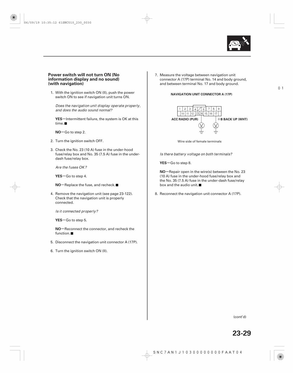
7. Measure the voltage between navigation unitconnector A (17P) terminal No. 14 and body ground,and between terminal No. 17 and body ground.
Go to step 8.
Repair open in the wire(s) between the No. 23(10 A) fuse in the under-hood fuse/relay box andthe No. 35 (7.5 A) fuse in the under-dash fuse/relaybox and the audio unit.
8. Reconnect the navigation unit connector A (17P).
(cont’d)
Wire side of female terminals
Does the navigation unit display operate proper ly,and does the audio sound normal?
Are the fuses OK ?
Is it connected proper ly?
Is there battery voltage on both terminals?
06/09/19 10:35:12 61SNC010_230_0030
02
03
SNC7AN0J10300000000FAAT05
-
-
-
-
-
-
-
-
YES
NO
YES
NO
YES
NO
YES
NO
Power switch will not turn ON (Noinformation display and no sound)(without navigation)
23-3023-30
Audio System
Symptom Troubleshooting (cont’d)
RADIO GND (BLK)
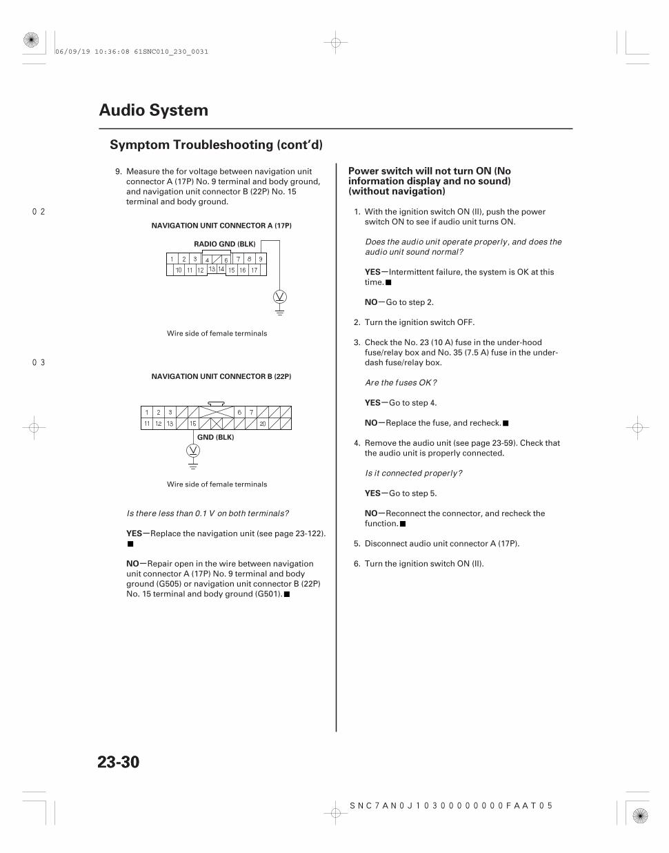
NAVIGATION UNIT CONNECTOR A (17P)
GND (BLK)
NAVIGATION UNIT CONNECTOR B (22P)
9. Measure the for voltage between navigation unitconnector A (17P) No. 9 terminal and body ground,and navigation unit connector B (22P) No. 15terminal and body ground.
Replace the navigation unit (see page 23-122).
Repair open in the wire between navigationunit connector A (17P) No. 9 terminal and bodyground (G505) or navigation unit connector B (22P)No. 15 terminal and body ground (G501).
1. With the ignition switch ON (II), push the powerswitch ON to see if audio unit turns ON.
Intermittent failure, the system is OK at thistime.
Go to step 2.
2. Turn the ignition switch OFF.
3. Check the No. 23 (10 A) fuse in the under-hoodfuse/relay box and No. 35 (7.5 A) fuse in the under-dash fuse/relay box.
Go to step 4.
Replace the fuse, and recheck.
4. Remove the audio unit (see page 23-59). Check thatthe audio unit is properly connected.
Go to step 5.
Reconnect the connector, and recheck thefunction.
5. Disconnect audio unit connector A (17P).
6. Turn the ignition switch ON (II).
Wire side of female terminals
Wire side of female terminals
Is there less than 0.1 V on both terminals?
Does the audio unit operate proper ly, and does theaudio unit sound normal?
Are the fuses OK ?
Is it connected proper ly?
06/09/19 10:36:08 61SNC010_230_0031
01
02
04
SNC7AN1J10300000000FAAT06
+
-
-
-
-
-
-
-
-
YES
NO
YES
NO
YES
NO
YES
NO
Power will not turn OFF (with navigation)
23-3123-31
AUDIO UNIT CONNECTOR A (17P)
B BACK UP (WHT)ACC RADIO (PUR)
AUDIO UNIT CONNECTOR A (17P)
RADIO GND (BLK)
ACC RADIO (PUR)
NAVIGATION UNIT CONNECTOR A (17P)
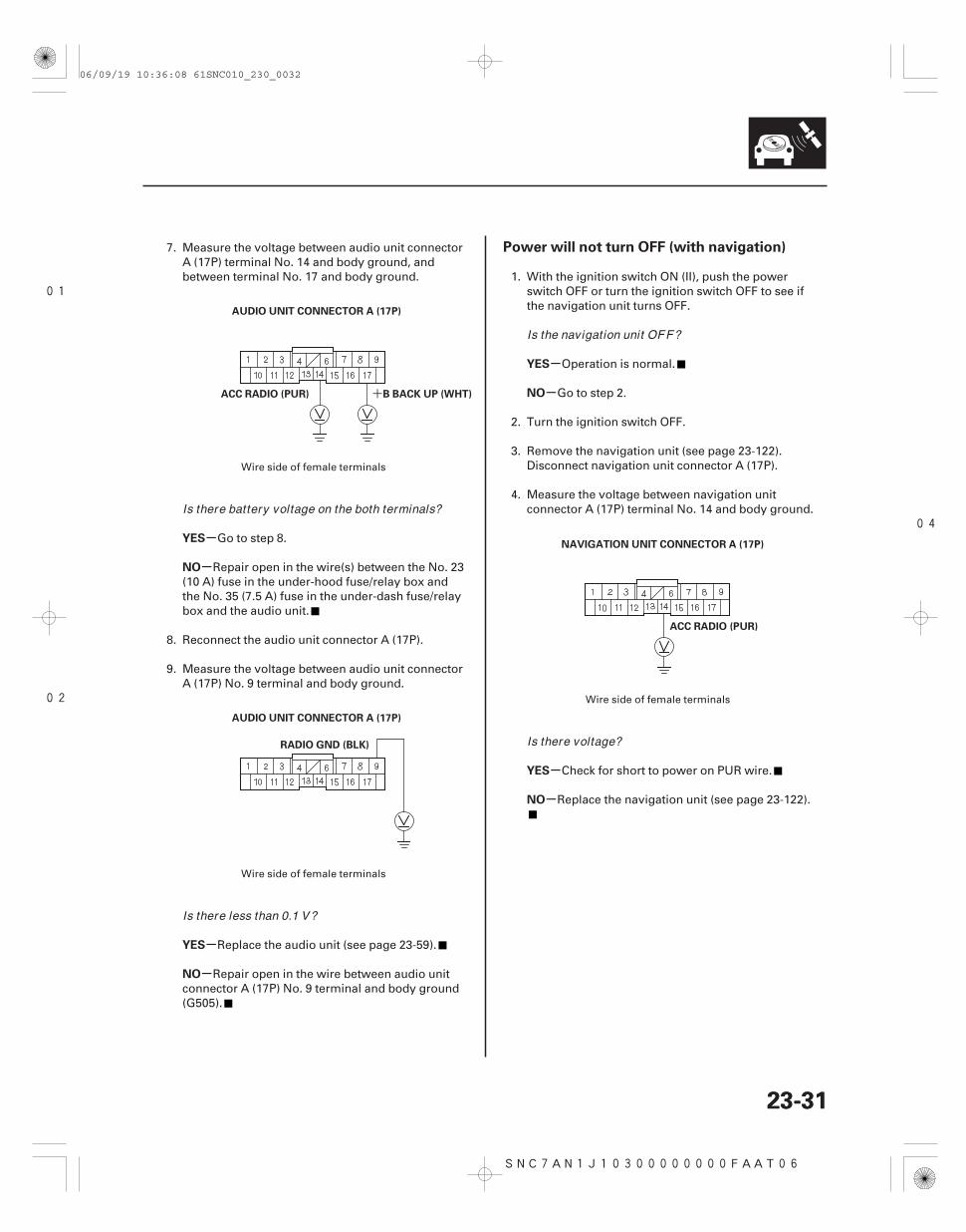
7. Measure the voltage between audio unit connectorA (17P) terminal No. 14 and body ground, andbetween terminal No. 17 and body ground.
Go to step 8.
Repair open in the wire(s) between the No. 23(10 A) fuse in the under-hood fuse/relay box andthe No. 35 (7.5 A) fuse in the under-dash fuse/relaybox and the audio unit.
8. Reconnect the audio unit connector A (17P).
9. Measure the voltage between audio unit connectorA (17P) No. 9 terminal and body ground.
Replace the audio unit (see page 23-59).
Repair open in the wire between audio unitconnector A (17P) No. 9 terminal and body ground(G505).
1. With the ignition switch ON (II), push the powerswitch OFF or turn the ignition switch OFF to see ifthe navigation unit turns OFF.
Operation is normal.
Go to step 2.
2. Turn the ignition switch OFF.
3. Remove the navigation unit (see page 23-122).Disconnect navigation unit connector A (17P).
4. Measure the voltage between navigation unitconnector A (17P) terminal No. 14 and body ground.
Check for short to power on PUR wire.
Replace the navigation unit (see page 23-122).
Wire side of female terminals
Wire side of female terminals
Wire side of female terminals
Is there battery voltage on the both terminals?
Is there less than 0.1 V?
Is the navigation unit OFF?
Is there voltage?
06/09/19 10:36:08 61SNC010_230_0032
03
SNC7AN0J10300000000FAAT07 SNC7AN1J10300000000FAAT05
-
-
-
-
-
-
-
-
-
-
-
-
Power will not turn OFF (without navigation) No sound is heard from speaker(s) (display isnormal) (with navigation)
YES
NO
YES
NO
YES
NO
YES
NO
YES
NO
YES
NO
23-3223-32
Audio System
Symptom Troubleshooting (cont’d)
AUDIO UNIT CONNECTOR A (17P)
ACC RADIO (PUR)
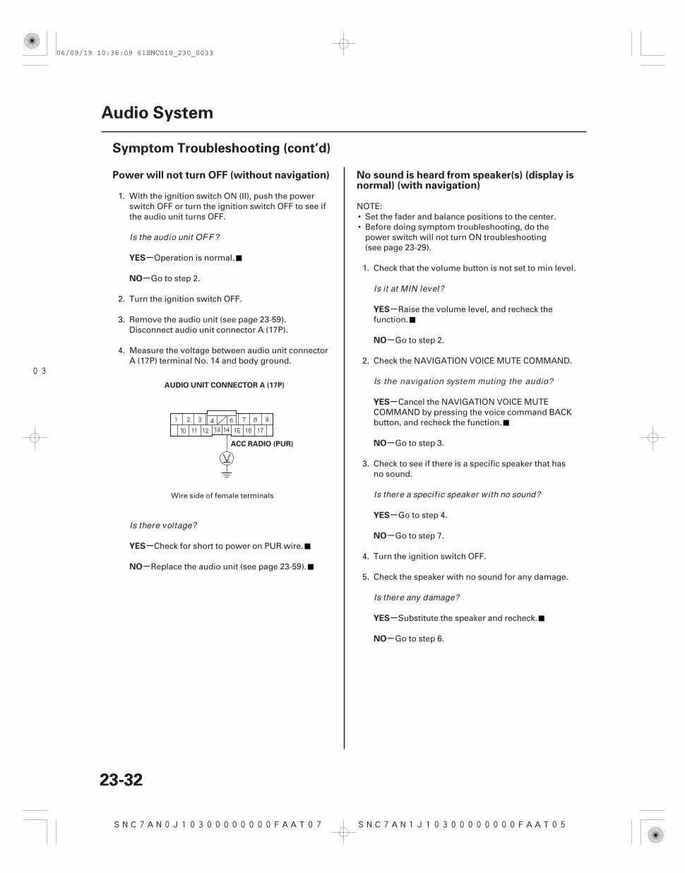
1. With the ignition switch ON (II), push the powerswitch OFF or turn the ignition switch OFF to see ifthe audio unit turns OFF.
Operation is normal.
Go to step 2.
2. Turn the ignition switch OFF.
3. Remove the audio unit (see page 23-59).Disconnect audio unit connector A (17P).
4. Measure the voltage between audio unit connectorA (17P) terminal No. 14 and body ground.
Check for short to power on PUR wire.
Replace the audio unit (see page 23-59).
NOTE:• Set the fader and balance positions to the center.• Before doing symptom troubleshooting, do the
power switch will not turn ON troubleshooting(see page 23-29).
1. Check that the volume button is not set to min level.
Raise the volume level, and recheck thefunction.
Go to step 2.
2. Check the NAVIGATION VOICE MUTE COMMAND.
Cancel the NAVIGATION VOICE MUTECOMMAND by pressing the voice command BACKbutton, and recheck the function.
Go to step 3.
3. Check to see if there is a specific speaker that hasno sound.
Go to step 4.
Go to step 7.
4. Turn the ignition switch OFF.
5. Check the speaker with no sound for any damage.
Substitute the speaker and recheck.
Go to step 6.
Wire side of female terminals
Is the audio unit OFF?
Is there voltage?
Is it at MIN level?
Is the navigation system muting the audio?
Is there a specif ic speaker with no sound?
Is there any damage?
06/09/19 10:36:09 61SNC010_230_0033
+-+-
+-+-
05
+
+
-
---
+
+
-
-
-
-
-
-
-
-
YES
NO
YES
NO
Speaker Terminal Wire color
YES
NO
YES
NO
23-33
RR R (BLU)
FR R(GRY)
RR R(ORN)
FR R (BRN)FR L (PNK)
RR L(BRN)
RR L (YEL)
FR L(LT GRN)
NAVIGATION UNIT CONNECTOR A (17P)
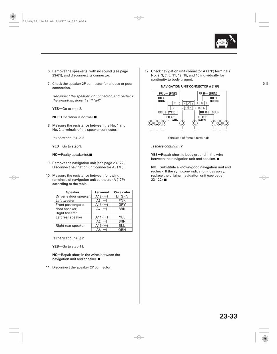
6. Remove the speaker(s) with no sound (see page23-61), and disconnect its connector.
7. Check the speaker 2P connector for a loose or poorconnection.
Go to step 8.
Operation is normal.
8. Measure the resistance between the No. 1 andNo. 2 terminals of the speaker connector.
Go to step 9.
Faulty speaker(s).
9. Remove the navigation unit (see page 23-122).Disconnect navigation unit connector A (17P).
10. Measure the resistance between followingterminals of navigation unit connector A (17P)according to the table.
Driver’s door speaker,Left tweeter
A12 ( ) LT GRNA3 ( ) PNK
Front passenger’sdoor speaker,Right tweeter
A15 ( ) GRYA7 ( ) BRN
Left rear speaker A11 ( ) YELA2 ( ) BRN
Right rear speaker A16 ( ) BLUA8 ( ) ORN
Go to step 11.
Repair short in the wires between thenavigation unit and speaker.
11. Disconnect the speaker 2P connector.
12. Check navigation unit connector A (17P) terminalsNo. 2, 3, 7, 8, 11, 12, 15, and 16 individually forcontinuity to body ground.
Repair short to body ground in the wirebetween the navigation unit and speaker.
Substitute a known-good navigation unit andrecheck. If the symptom/ indication goes away,replace the original navigation unit (see page23-122).
Wire side of female terminals
Reconnect the speaker 2P connector, and recheckthe symptom; does it sti l l f ail?
Is there about 4 ?
Is there about 4 ?
Is there continuity?
06/09/19 10:36:09 61SNC010_230_0034
+-+-
+-+-
SNC7AN0J10300000000FAAT00
-
-
-
-
-
-
-
-
-
-
-
-
No sound is heard from speaker(s) (display isnormal) (without navigation)
YES
NO
YES
NO
YES
NO
YES
NO
YES
NO
Speaker Terminal Wire color
YES
NO
23-34
Audio System
Symptom Troubleshooting (cont’d)
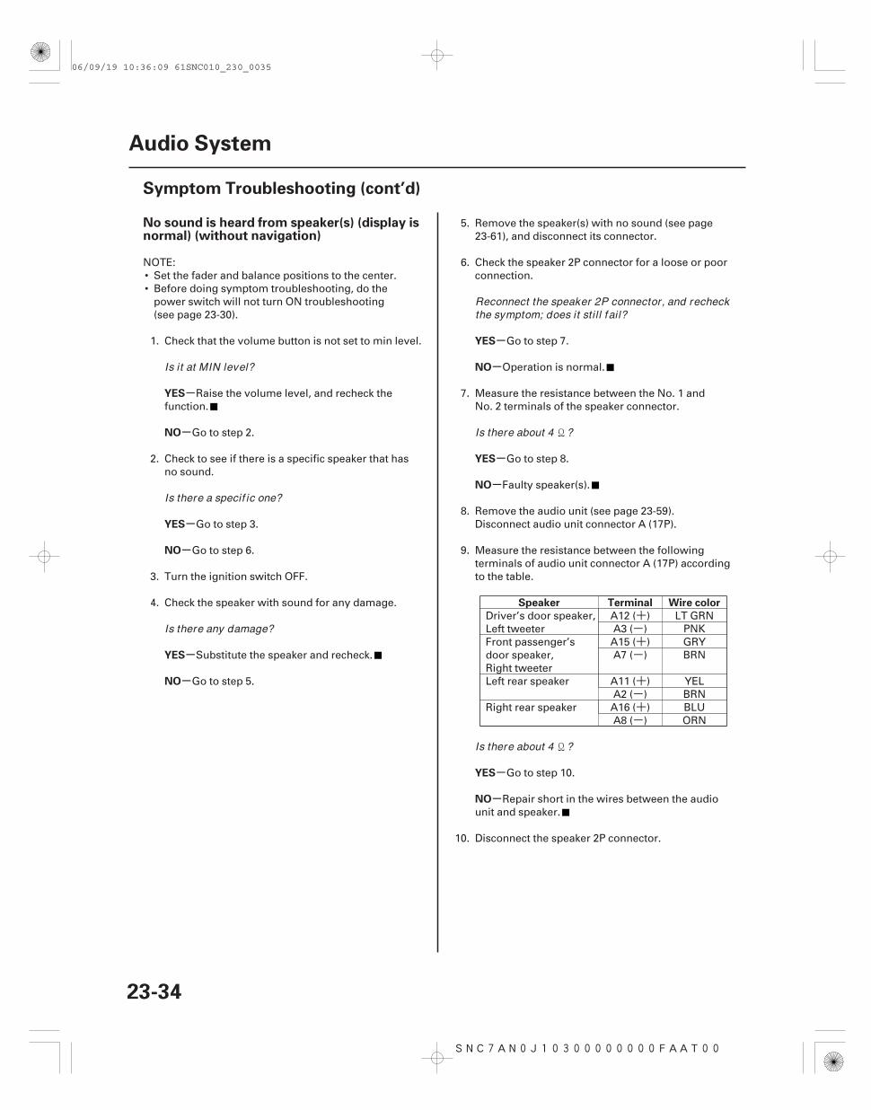
NOTE:• Set the fader and balance positions to the center.• Before doing symptom troubleshooting, do the
power switch will not turn ON troubleshooting(see page 23-30).
1. Check that the volume button is not set to min level.
Raise the volume level, and recheck thefunction.
Go to step 2.
2. Check to see if there is a specific speaker that hasno sound.
Go to step 3.
Go to step 6.
3. Turn the ignition switch OFF.
4. Check the speaker with sound for any damage.
Substitute the speaker and recheck.
Go to step 5.
5. Remove the speaker(s) with no sound (see page23-61), and disconnect its connector.
6. Check the speaker 2P connector for a loose or poorconnection.
Go to step 7.
Operation is normal.
7. Measure the resistance between the No. 1 andNo. 2 terminals of the speaker connector.
Go to step 8.
Faulty speaker(s).
8. Remove the audio unit (see page 23-59).Disconnect audio unit connector A (17P).
9. Measure the resistance between the followingterminals of audio unit connector A (17P) accordingto the table.
Driver’s door speaker,Left tweeter
A12 ( ) LT GRNA3 ( ) PNK
Front passenger’sdoor speaker,Right tweeter
A15 ( ) GRYA7 ( ) BRN
Left rear speaker A11 ( ) YELA2 ( ) BRN
Right rear speaker A16 ( ) BLUA8 ( ) ORN
Go to step 10.
Repair short in the wires between the audiounit and speaker.
10. Disconnect the speaker 2P connector.
Is it at MIN level?
Is there a specif ic one?
Is there any damage?
Reconnect the speaker 2P connector, and recheckthe symptom; does it sti l l f ail?
Is there about 4 ?
Is there about 4 ?
06/09/19 10:36:09 61SNC010_230_0035
04
SNC7AN3J10300000000FAAT12
+
+
-
---
+
+
-
--
-
-
-
YES
NO
YES
NO
XM receiver connector Wire color
YES
NO
Poor or no sound with XM radio (navigationunit can display XM channels) (withnavigation)
23-3523-35
AUDIO UNIT CONNECTOR A (17P)
RR R (BLU)
FR R(GRY)
RR R(ORN)
FR R (BRN)FR L (PNK)
RR L(BRN)
RR L (YEL)
FR L(LT GRN)
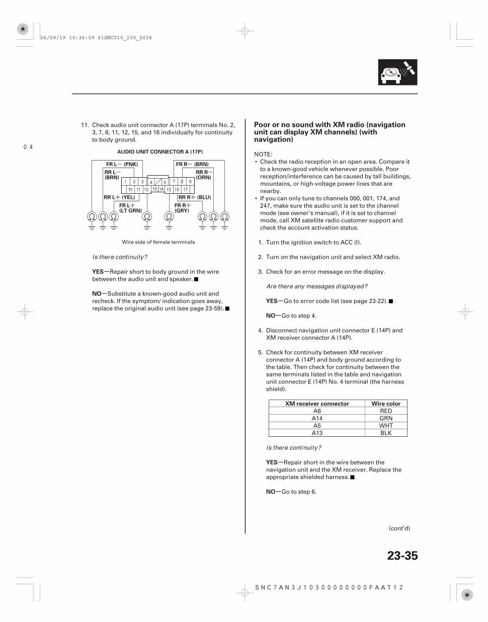
11. Check audio unit connector A (17P) terminals No. 2,3, 7, 8, 11, 12, 15, and 16 individually for continuityto body ground.
Repair short to body ground in the wirebetween the audio unit and speaker.
Substitute a known-good audio unit andrecheck. If the symptom/ indication goes away,replace the original audio unit (see page 23-59).
NOTE:• Check the radio reception in an open area. Compare it
to a known-good vehicle whenever possible. Poorreception/interference can be caused by tall buildings,mountains, or high-voltage power lines that arenearby.
• If you can only tune to channels 000, 001, 174, and247, make sure the audio unit is set to the channelmode (see owner’s manual), if it is set to channelmode, call XM satellite radio customer support andcheck the account activation status.
1. Turn the ignition switch to ACC (I).
2. Turn on the navigation unit and select XM radio.
3. Check for an error message on the display.
Go to error code list (see page 23-22).
Go to step 4.
4. Disconnect navigation unit connector E (14P) andXM receiver connector A (14P).
5. Check for continuity between XM receiverconnector A (14P) and body ground according tothe table. Then check for continuity between thesame terminals listed in the table and navigationunit connector E (14P) No. 4 terminal (the harnessshield).
A6 REDA14 GRNA5 WHTA13 BLK
Repair short in the wire between thenavigation unit and the XM receiver. Replace theappropriate shielded harness.
Go to step 6.
(cont’d)
Wire side of female terminals
Is there continuity?
Are there any messages displayed?
Is there continuity?
06/09/19 10:36:09 61SNC010_230_0036
*01
SNC7AN3J10300000000FAAT13
+-
-
-
-
XM receiver
connector
Navigation
unit connector
Wire color
YES
NO
YES
NO
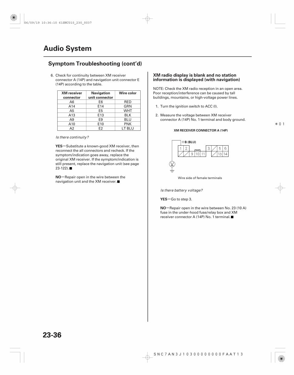
XM radio display is blank and no stationinformation is displayed (with navigation)
23-3623-36
Audio System
Symptom Troubleshooting (cont’d)
XM RECEIVER CONNECTOR A (14P)
B (BLU)
6. Check for continuity between XM receiverconnector A (14P) and navigation unit connector E(14P) according to the table.
A6 E6 REDA14 E14 GRNA5 E5 WHTA13 E13 BLKA9 E9 BLUA10 E10 PNKA2 E2 LT BLU
Substitute a known-good XM receiver, thenreconnect the all connectors and recheck. If thesymptom/indication goes away, replace theoriginal XM receiver. If the symptom/indication isstill present, replace the navigation unit (see page23-122).
Repair open in the wire between thenavigation unit and the XM receiver.
NOTE: Check the XM radio reception in an open area.Poor reception/interference can be caused by tallbuildings, mountains, or high-voltage power lines.
1. Turn the ignition switch to ACC (I).
2. Measure the voltage between XM receiverconnector A (14P) No. 1 terminal and body ground.
Go to step 3.
Repair open in the wire between No. 23 (10 A)fuse in the under-hood fuse/relay box and XMreceiver connector A (14P) No. 1 terminal.
Wire side of female terminals
Is there continuity?
Is there battery voltage?
06/09/19 10:36:10 61SNC010_230_0037
*02 *03
-
-
-
-
YES
NO
YES
NO
23-37
XM RECEIVER CONNECTOR A (14P)
GND (BLK)
NAVIGATION UNIT CONNECTOR E (14P)
SAT SYS ACC (LT BLU)
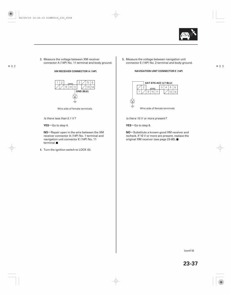
3. Measure the voltage between XM receiverconnector A (14P) No. 11 terminal and body ground.
Go to step 4.
Repair open in the wire between the XMreceiver connector A (14P) No. 1 terminal andnavigation unit connector E (14P) No. 11terminal.
4. Turn the ignition switch to LOCK (0).
5. Measure the voltage between navigation unitconnector E (14P) No. 2 terminal and body ground.
Go to step 6.
Substitute a known-good XM receiver andrecheck. If 10 V or more are present, replace theoriginal XM receiver (see page 23-60).
(cont’d)
Wire side of female terminals Wire side of female terminals
Is there less than 0.1 V? Is there 10 V or more present?
06/09/19 10:36:10 61SNC010_230_0038
*04
-
-
-
-
-
-
YES
NO
XM receiver connector Wire color
YES
NO
XM receiver
connector
Navigation
unit connector
Wire color
YES
NO
23-38
Audio System
Symptom Troubleshooting (cont’d)
NAVIGATION UNIT CONNECTOR E (14P)
SAT SYS ACC (LT BLU)
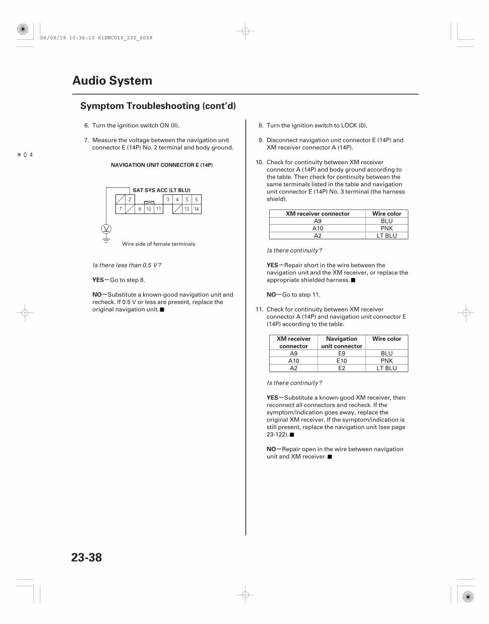
6. Turn the ignition switch ON (II).
7. Measure the voltage between the navigation unitconnector E (14P) No. 2 terminal and body ground.
Go to step 8.
Substitute a known-good navigation unit andrecheck. If 0.5 V or less are present, replace theoriginal navigation unit.
8. Turn the ignition switch to LOCK (0).
9. Disconnect navigation unit connector E (14P) andXM receiver connector A (14P).
10. Check for continuity between XM receiverconnector A (14P) and body ground according tothe table. Then check for continuity between thesame terminals listed in the table and navigationunit connector E (14P) No. 3 terminal (the harnessshield).
A9 BLUA10 PNKA2 LT BLU
Repair short in the wire between thenavigation unit and the XM receiver, or replace theappropriate shielded harness.
Go to step 11.
11. Check for continuity between XM receiverconnector A (14P) and navigation unit connector E(14P) according to the table.
A9 E9 BLUA10 E10 PNKA2 E2 LT BLU
Substitute a known-good XM receiver, thenreconnect all connectors and recheck. If thesymptom/indication goes away, replace theoriginal XM receiver. If the symptom/indication isstill present, replace the navigation unit (see page23-122).
Repair open in the wire between navigationunit and XM receiver.
Wire side of female terminals
Is there less than 0.5 V?
Is there continuity?
Is there continuity?
06/09/19 10:36:10 61SNC010_230_0039
SNC7A00J10300000000FAAT00 SNC7AN1J10300000000FAAT13
-
--
-
-
-
Audio system sound is weak or distorted(display is normal)
Navigation unit button illumination does notwork (with navigation)
YES
NO
YES
NO
YES
NO
23-3923-39
1. Check for sound in each mode (AM, FM, and disc).
Intermittent failure. The system is OK at thistime. Check for loose connections at the navigationunit, audio unit, and each speaker.
Speakers all work, sound quality is poor.
• If the sound quality is poor only with AM or FMradio, go to poor AM or FM radio reception orinterference (see page 23-23).
• If sound is poor in all modes, go to sound qualitydiagnosis (see page 23-54).
1. Turn the ignition switch to ON (II).
2. Turn the combination lighting switch to the parkinglight position.
3. Check the illumination of the navigation unitbuttons.
Intermittent problem: the navigation unit isOK at this time. Check for loose or poorconnections at the navigation unit connector A(17P).
Go to step 4.
4. Check the illumination of several other buttons notrelated to the navigation system.
Go to step 5.
Troubleshoot the interior lights. Start bychecking the No. 14 (7.5 A) fuse in the under-dashfuse/relay box. If the fuse is OK, check for an openin the wire between the under-dash fuse/relay boxand the navigation unit.
5. Turn the ignition switch to LOCK (0).
6. Disconnect navigation unit connector A (17P).
7. Disconnect gauge control module (tach) 36Pconnector.
(cont’d)
Is there sound f rom the speakers, and is the soundquality normal in each mode?
Are the buttons il luminated?
Are the buttons il luminated?
06/09/19 10:36:10 61SNC010_230_0040
*06
07
SNC7AN0J10300000000FAAT14
-
-
+
-
-
-
-
-
-
-
-
YES
NO
YES
NO
YES
NO
YES
NO
Audio unit button illumination does notwork
23-4023-40
Audio System
Symptom Troubleshooting (cont’d)
NAVIGATION UNIT CONNECTOR A (17P)
ILL (RED)
GAUGE CONTROL MODULE (TACH) 36P CONNECTOR
ILL (RED)
NAVIGATION UNIT CONNECTOR A (17P)
ILL (GRY)
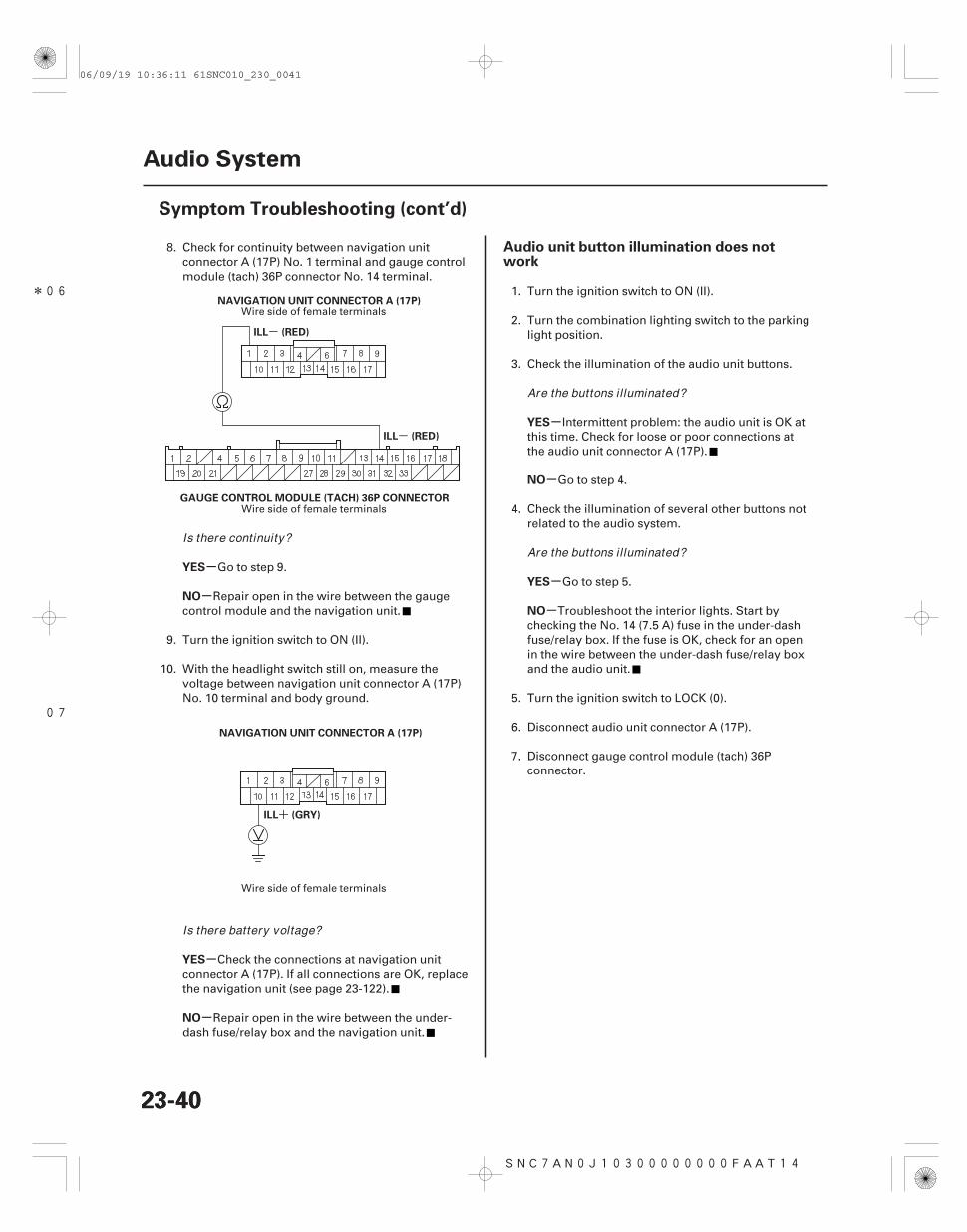
8. Check for continuity between navigation unitconnector A (17P) No. 1 terminal and gauge controlmodule (tach) 36P connector No. 14 terminal.
Go to step 9.
Repair open in the wire between the gaugecontrol module and the navigation unit.
9. Turn the ignition switch to ON (II).
10. With the headlight switch still on, measure thevoltage between navigation unit connector A (17P)No. 10 terminal and body ground.
Check the connections at navigation unitconnector A (17P). If all connections are OK, replacethe navigation unit (see page 23-122).
Repair open in the wire between the under-dash fuse/relay box and the navigation unit.
1. Turn the ignition switch to ON (II).
2. Turn the combination lighting switch to the parkinglight position.
3. Check the illumination of the audio unit buttons.
Intermittent problem: the audio unit is OK atthis time. Check for loose or poor connections atthe audio unit connector A (17P).
Go to step 4.
4. Check the illumination of several other buttons notrelated to the audio system.
Go to step 5.
Troubleshoot the interior lights. Start bychecking the No. 14 (7.5 A) fuse in the under-dashfuse/relay box. If the fuse is OK, check for an openin the wire between the under-dash fuse/relay boxand the audio unit.
5. Turn the ignition switch to LOCK (0).
6. Disconnect audio unit connector A (17P).
7. Disconnect gauge control module (tach) 36Pconnector.
Wire side of female terminals
Wire side of female terminals
Wire side of female terminals
Is there continuity?
Is there battery voltage?
Are the buttons il luminated?
Are the buttons il luminated?
06/09/19 10:36:11 61SNC010_230_0041
*05 06
-
-
+
-
-
-
-
YES
NO
YES
NO
23-41
AUDIO UNIT CONNECTOR A (17P)
ILL (RED)
GAUGE CONTROL MODULE (TACH) 36P CONNECTOR
ILL (RED)
AUDIO UNIT CONNECTOR A (17P)
ILL (GRY)
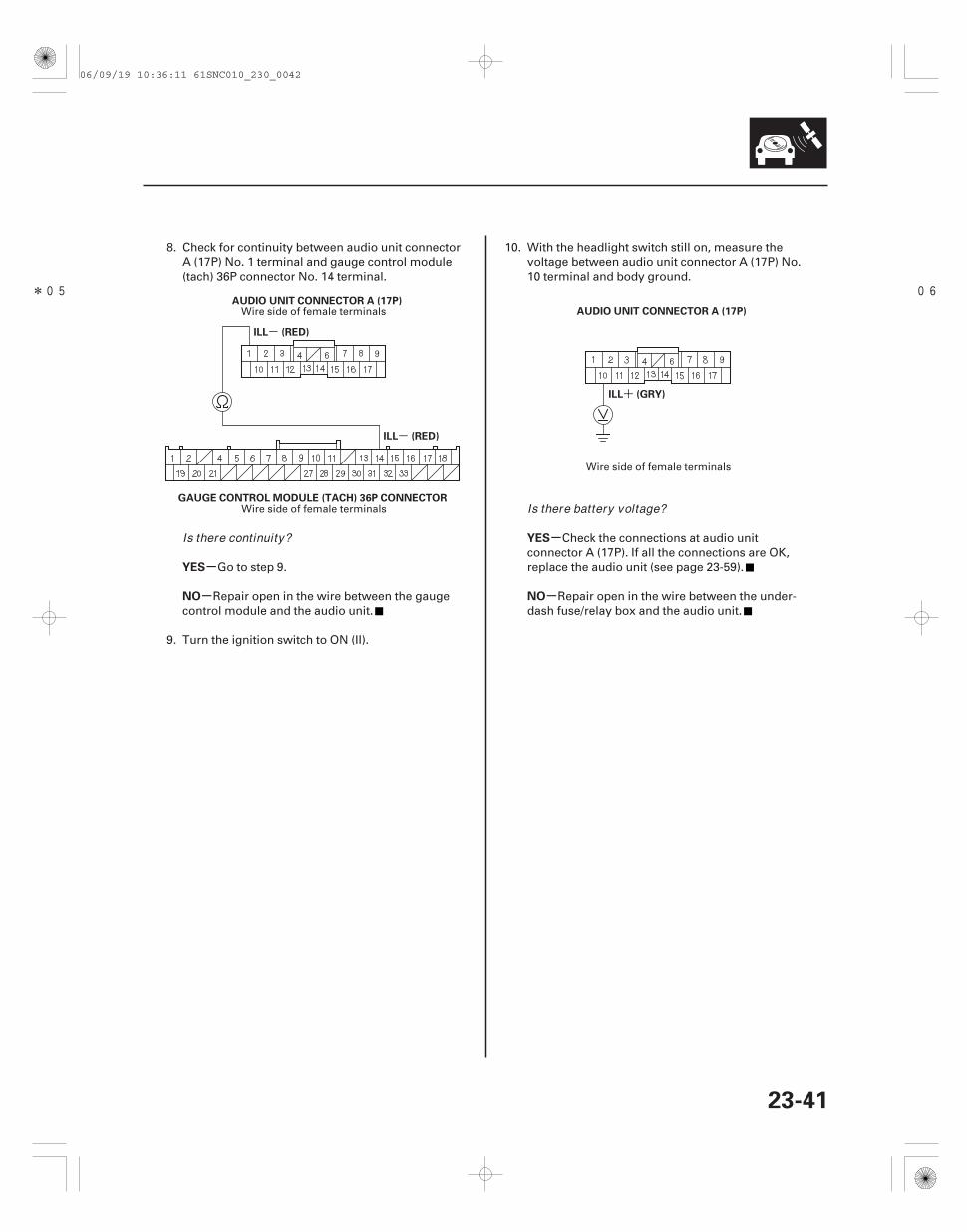
8. Check for continuity between audio unit connectorA (17P) No. 1 terminal and gauge control module(tach) 36P connector No. 14 terminal.
Go to step 9.
Repair open in the wire between the gaugecontrol module and the audio unit.
9. Turn the ignition switch to ON (II).
10. With the headlight switch still on, measure thevoltage between audio unit connector A (17P) No.10 terminal and body ground.
Check the connections at audio unitconnector A (17P). If all the connections are OK,replace the audio unit (see page 23-59).
Repair open in the wire between the under-dash fuse/relay box and the audio unit.
Wire side of female terminals
Wire side of female terminals
Wire side of female terminals
Is there continuity?
Is there battery voltage?
06/09/19 10:36:11 61SNC010_230_0042
SNC7A00J10300000000FAAT10 SNC7AN3J10300000000FAAT14
-
-
-
-
-
-
-
-
Radio preset memory is lost XM radio preset memory is lost (withnavigation)
YES
NO
YES
NO
YES
NO
YES
NO
23-4223-42
Audio System
Symptom Troubleshooting (cont’d)
1. Set each of the radio station preset buttons.
Go to step 2.
• With navigation: Replace the navigation unit(see page 23-122).
• Without navigation: Replace the audio unit(see page 23-59).
2. Turn the ignition switch OFF for 1 minute, then turnit back to ON (II).
3. Test the preset buttons for proper recall operation.
System is normal at this time. Check theconnections at the navigation unit or audio unit.
• With navigation: Replace the navigation unit(see page 23-122).
• Without navigation: Replace the audio unit(see page 23-59).
NOTE: If you can only tune to channel 000, 001, 174,and 247, make sure the audio unit is set to the channelmode (see owner’s manual), if it is set to channel mode,call XM satellite radio customer support and check theaccount activation status.
1. Set each of the XM radio channel preset buttons.
Go to step 2.
Replace the navigation unit.
2. Turn the ignition switch OFF for 1 minute, then turnit back to ON (II).
3. Test all of the XM radio channel preset buttons forproper recall operation.
System is normal at this time. Check theconnections at the navigation unit.
Go to step 4.
4. Turn the ignition switch to LOCK (0).
Do each of the buttons set proper ly?
Do the preset buttons recall the set radio stations?
Do each of the XM radio channel preset buttonsset proper ly?
Do the preset buttons recall the set radio stations?
06/09/19 10:36:11 61SNC010_230_0043
*01
*02
*01
SNC7AN3J10300000000FAAT15
+
+
-
-
-
-
-
-
-
-
-
-
YES
NO
YES
NO
YES
NO
YES
NO
YES
NO
Error code: XM NO SIGNAL or XM ANTENNAis displayed
23-4323-43
XM RECEIVER CONNECTOR A (14P)
B (BLU)
XM RECEIVER CONNECTOR A (14P)
GND (BLK)
XM RECEIVER CONNECTOR A (14P)
B (BLU)
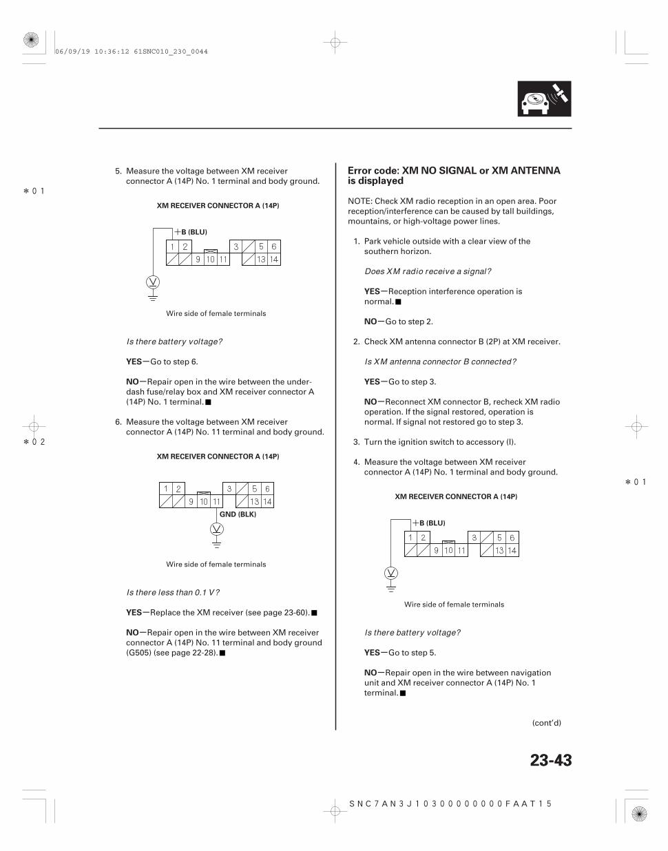
5. Measure the voltage between XM receiverconnector A (14P) No. 1 terminal and body ground.
Go to step 6.
Repair open in the wire between the under-dash fuse/relay box and XM receiver connector A(14P) No. 1 terminal.
6. Measure the voltage between XM receiverconnector A (14P) No. 11 terminal and body ground.
Replace the XM receiver (see page 23-60).
Repair open in the wire between XM receiverconnector A (14P) No. 11 terminal and body ground(G505) (see page 22-28).
NOTE: Check XM radio reception in an open area. Poorreception/interference can be caused by tall buildings,mountains, or high-voltage power lines.
1. Park vehicle outside with a clear view of thesouthern horizon.
Reception interference operation isnormal.
Go to step 2.
2. Check XM antenna connector B (2P) at XM receiver.
Go to step 3.
Reconnect XM connector B, recheck XM radiooperation. If the signal restored, operation isnormal. If signal not restored go to step 3.
3. Turn the ignition switch to accessory (I).
4. Measure the voltage between XM receiverconnector A (14P) No. 1 terminal and body ground.
Go to step 5.
Repair open in the wire between navigationunit and XM receiver connector A (14P) No. 1terminal.
(cont’d)
Wire side of female terminals
Wire side of female terminals
Wire side of female terminals
Is there battery voltage?
Is there less than 0.1 V?
Does XM radio receive a signal?
Is XM antenna connector B connected?
Is there battery voltage?
06/09/19 10:36:12 61SNC010_230_0044
*02
SNC7A00J10300000000FAAT40
-
-
-
-
-
-
-
-
YES
NO
YES
NO
YES
NO
YES
NO
Audio disc does not eject
23-4423-44
Audio System
Symptom Troubleshooting (cont’d)
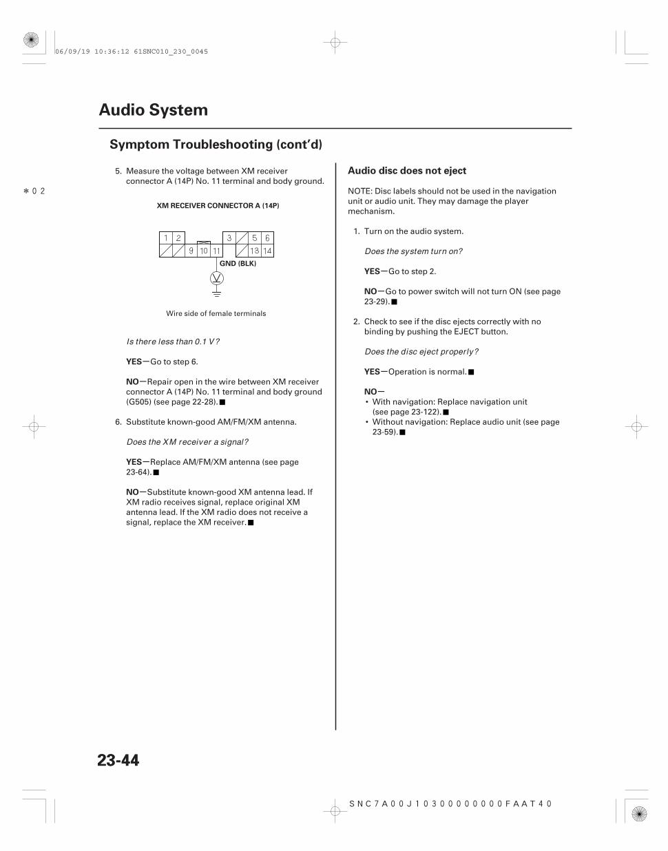
XM RECEIVER CONNECTOR A (14P)
GND (BLK)
5. Measure the voltage between XM receiverconnector A (14P) No. 11 terminal and body ground.
Go to step 6.
Repair open in the wire between XM receiverconnector A (14P) No. 11 terminal and body ground(G505) (see page 22-28).
6. Substitute known-good AM/FM/XM antenna.
Replace AM/FM/XM antenna (see page23-64).
Substitute known-good XM antenna lead. IfXM radio receives signal, replace original XMantenna lead. If the XM radio does not receive asignal, replace the XM receiver.
NOTE: Disc labels should not be used in the navigationunit or audio unit. They may damage the playermechanism.
1. Turn on the audio system.
Go to step 2.
Go to power switch will not turn ON (see page23-29).
2. Check to see if the disc ejects correctly with nobinding by pushing the EJECT button.
Operation is normal.
• With navigation: Replace navigation unit(see page 23-122).
• Without navigation: Replace audio unit (see page23-59).
Wire side of female terminals
Is there less than 0.1 V?
Does the XM receiver a signal?
Does the system turn on?
Does the disc eject proper ly?
06/09/19 10:36:12 61SNC010_230_0045
SNC7A00J10300000000FAAT21 SNC7A00J10300000000FAAT41
-
-
-
-
-
-
-
-
Audio disc does not load Radio tuner does not change stations
YES
NO
YES
NO
YES
NO
YES
NO
23-4523-45
NOTE:• Disc labels should not be used in the navigation unit
or audio unit. They may damage the playermechanism.
• Make sure the CD disc is compatible with the system(see the owner’s manual for more information).
1. Insert a known-good disc to see if the symptom canbe duplicated.
Operation is normal. If the disc loadsnormally, but will not play, go to audio disc doesnot play (see page 23-49).
Go to step 2.
2. Insert another disc.
The original disc is faulty.
• With navigation: Replace navigation unit(see page 23-122).
• Without navigation: Replace audio unit (see page23-59).
1. Check the audio information on the display panel.
Go to step 2.
Go to power switch will not turn ON (see page23-29).
2. Operate the tuning knob to see if the radio stationchanges.
Intermittent failure: the tuning knob is OK atthis time.
• With navigation: Replace the navigation unit(see page 23-122).
• Without navigation: Replace the audio unit(see page 23-59).
Does the disc load?
Does the disc load?
Does the audio information display proper ly?
Does the radio station change?
06/09/19 10:36:12 61SNC010_230_0046
SNC7A00J10300000000FAAT05 SNC7A00J10300000000FAAT22
-
-
-
-
-
-
-
-
-
-
Volume does not change Volume does not increase with speed
YES
NO
YES
NO
YES
NO
YES
NO
YES
NO
23-4623-46
Audio System
Symptom Troubleshooting (cont’d)
NOTE: Set the fader and balance positions to the center.
1. Listen for sound from the speakers.
Go to step 2.
Go to audio system sound is weak ordistorted, or no sound is heard from speakers, withnavigation (see page 23-32), without navigation(see page 23-34).
2. Operate the volume knob to see if the volumechanges.
Operation is normal.
• With navigation: Replace navigation unit(see page 23-122).
• Without navigation: Replace audio unit (see page23-59).
1. Test-drive the vehicle at highway speeds andmonitor if the volume increases.
Intermittent failure, the system is OK at thistime.
Go to step 2.
2. Verify if SVC mode setting in navigation, or audiounit sound set-up.
Change setting to ‘‘Mid’’ and retest.
Go to step 3.
3. Perform self-diagnostic function for vehicle speedpulse indication (see page 23-20).
Substitute a known-good navigation, oraudio unit and retest. If the symptom/indicationgoes away, replace the original navigation, oraudio unit.
Go to step 4.
Is the sound normal?
Does the volume change?
Does the volume increase?
Is the SVC set to of f?
Does self -diagnostic function indicate a VSPsignal?
06/09/19 10:36:12 61SNC010_230_0047
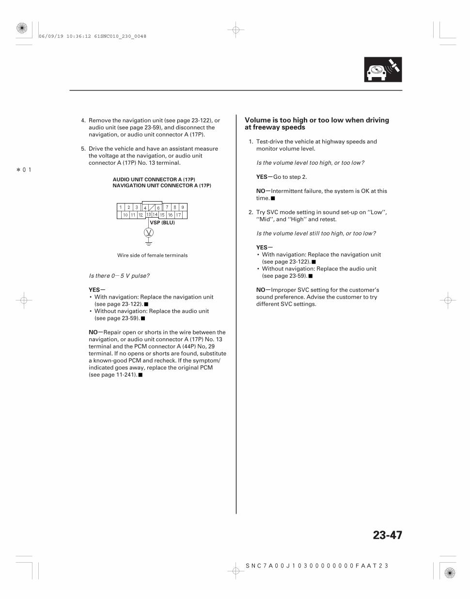
-
*01
SNC7A00J10300000000FAAT23
-
-
-
-
-
-YES
NO
YES
NO
YES
NO
Volume is too high or too low when drivingat freeway speeds
23-4723-47
AUDIO UNIT CONNECTOR A (17P)
VSP (BLU)
NAVIGATION UNIT CONNECTOR A (17P)
4. Remove the navigation unit (see page 23-122), oraudio unit (see page 23-59), and disconnect thenavigation, or audio unit connector A (17P).
5. Drive the vehicle and have an assistant measurethe voltage at the navigation, or audio unitconnector A (17P) No. 13 terminal.
• With navigation: Replace the navigation unit(see page 23-122).
• Without navigation: Replace the audio unit(see page 23-59).
Repair open or shorts in the wire between thenavigation, or audio unit connector A (17P) No. 13terminal and the PCM connector A (44P) No, 29terminal. If no opens or shorts are found, substitutea known-good PCM and recheck. If the symptom/indicated goes away, replace the original PCM(see page 11-241).
1. Test-drive the vehicle at highway speeds andmonitor volume level.
Go to step 2.
Intermittent failure, the system is OK at thistime.
2. Try SVC mode setting in sound set-up on ‘‘Low’’,‘‘Mid’’, and ‘‘High’’ and retest.
• With navigation: Replace the navigation unit(see page 23-122).
• Without navigation: Replace the audio unit(see page 23-59).
Improper SVC setting for the customer’ssound preference. Advise the customer to trydifferent SVC settings.
Wire side of female terminals
Is there 0 5 V pulse?
Is the volume level too high, or too low?
Is the volume level sti l l too high, or too low?
06/09/19 10:36:12 61SNC010_230_0048
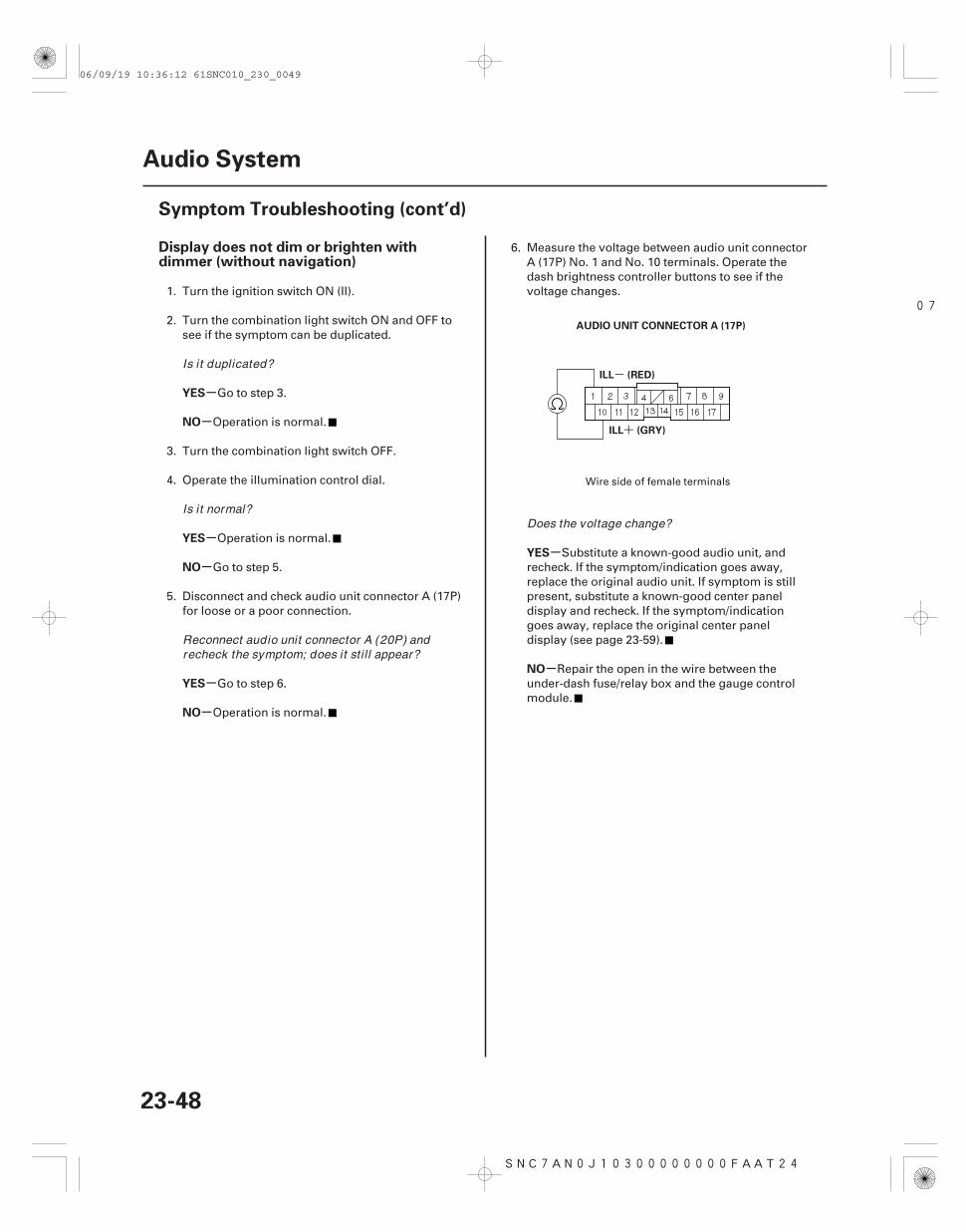
07
SNC7AN0J10300000000FAAT24
+
-
-
-
-
-
-
-
-
-
Display does not dim or brighten withdimmer (without navigation)
YES
NO
YES
NO
YES
NO
YES
NO
23-48
Audio System
Symptom Troubleshooting (cont’d)
AUDIO UNIT CONNECTOR A (17P)
ILL (GRY)
ILL (RED)
1. Turn the ignition switch ON (II).
2. Turn the combination light switch ON and OFF tosee if the symptom can be duplicated.
Go to step 3.
Operation is normal.
3. Turn the combination light switch OFF.
4. Operate the illumination control dial.
Operation is normal.
Go to step 5.
5. Disconnect and check audio unit connector A (17P)for loose or a poor connection.
Go to step 6.
Operation is normal.
6. Measure the voltage between audio unit connectorA (17P) No. 1 and No. 10 terminals. Operate thedash brightness controller buttons to see if thevoltage changes.
Substitute a known-good audio unit, andrecheck. If the symptom/indication goes away,replace the original audio unit. If symptom is stillpresent, substitute a known-good center paneldisplay and recheck. If the symptom/indicationgoes away, replace the original center paneldisplay (see page 23-59).
Repair the open in the wire between theunder-dash fuse/relay box and the gauge controlmodule.
Wire side of female terminals
Is it duplicated?
Is it normal?
Reconnect audio unit connector A (20P) andrecheck the symptom; does it sti l l appear?
Does the voltage change?
06/09/19 10:36:12 61SNC010_230_0049
SNC7A00J10300000000FAAT42
-
SNC7A00J10300000000FAAT07
-
-
-
-
-
-
-
-
-
-
Special Tools Required
YES
NO
YES
NO
YES
NO
Special Tools Required
YES
NO
YES
NO
Audio disc does not play Audio disc skips
23-4923-49
Diagnostics CD 07AAZ-SDBA100
1. Try loading a known-good disc.
Go to step 2.
Go to audio disc does not load (see page23-45).
2. Insert another known-good disc to see if thesymptom can be duplicated.
Operation is normal.
Go to step 3.
3. Insert the audio diagnostic CD (T/N 07AAZ-SDBA100) in the navigation unit or audio unit.
The original disc is faulty, or has anunreadable format.
• With navigation: Replace navigation unit(see page 23-122).
• Without navigation: Replace audio unit (see page23-59).
Diagnostics CD 07AAZ-SDBA100
1. Confirm the vehicles tires are properly inflated.
2. Check the customer’s CD for scratches, fingerprints,and marks.
NOTE: The following test should be done withaudio unit bass and treble set to the customer’slistening settings. When comparing to known-goodvehicles, compare with the same model and trimlevel.
3. Test-drive the vehicle to identify when thecustomer’s CD skips. The audio diagnostic CD (T/N07AAZ-SDBA100) can be used if the customers CDis not available. Use tracks 10 12.
Go to step 4.
Operation is normal.
4. Compare the customer’s CD that skips in a known-good vehicle under the same conditions.
Operation is normal.
Go to step 5.
NOTE: The following test should be done withvehicle parked and engine running.
(cont’d)
Does the disc load?
Does the disc play?
Does the disc play?
Does the CD skip?
Does the CD skip in the known-good vehicle underthe same conditions?
06/09/19 10:36:13 61SNC010_230_0050
-
--
- +
SNC7A00J10300000000FAAT11
-
-
-
-
-
-
-
-
YES
NO
YES
NO
YES
NO
YES
NO
Audio remote switch does not work properly
23-5023-50
Audio System
Symptom Troubleshooting (cont’d)
5. Insert the diagnostic skip test CD (T/N 07AAZ-SDBA300) (ABEX TCD 721). Play tracks 2 11, andnote the track number(s) where the CD startsskipping. Do the same test on a known-goodvehicle.
Operation is normal.
Go to step 6.
6. Insert the diagnostic skip test CD (T/N 07AAZ-SDBA200) (ABEX TCD 725B). Play tracks 7 11 andtracks 13 15, and note the track number(s) wherethe CD starts skipping. Do the same test on aknown-good vehicle.
Operation is normal.
• With navigation: Replace navigation unit(see page 23-122).
• Without navigation: Replace audio unit (see page23-59).
1. Test the audio remote switch (see page 23-63).
Go to step 2.
Replace the audio remote switch.
2. Check the audio unit operation (volume up, volumedown, CH ( ), CH ( ), MODE).
• With navigation: Go to step 3.• Without navigation: Go to step 6.
• With navigation: Replace the navigation unit(see page 23-122).
• Without navigation: Replace the audio unit(see page 23-59).
3. Remove the navigation unit (see page 23-122).
Does the CD skip on same track number(s) asknown-good vehicle?
Does the CD skip on same track number(s) asknown-good vehicle?
Is the audio remote switch OK ?
Is the audio unit operation OK ?
06/09/19 10:36:13 61SNC010_230_0051
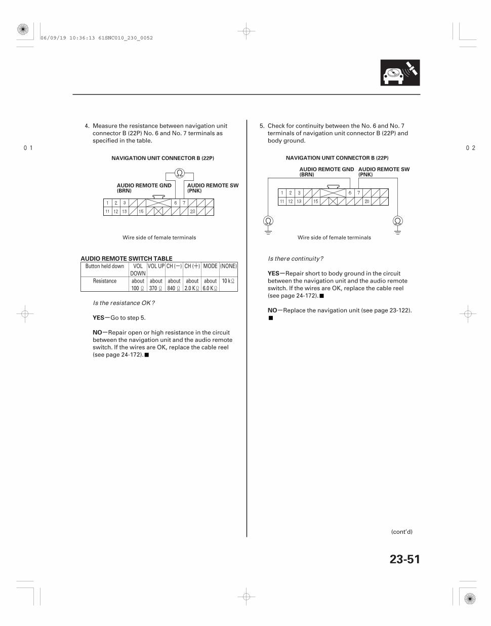
- +
01 02
-
-
-
-
AUDIO REMOTE SWITCH TABLE
YES
NO
YES
NO
23-51
NAVIGATION UNIT CONNECTOR B (22P)
AUDIO REMOTE GND(BRN)
AUDIO REMOTE SW(PNK)
NAVIGATION UNIT CONNECTOR B (22P)
AUDIO REMOTE GND(BRN)
AUDIO REMOTE SW(PNK)
4. Measure the resistance between navigation unitconnector B (22P) No. 6 and No. 7 terminals asspecified in the table.
Go to step 5.
Repair open or high resistance in the circuitbetween the navigation unit and the audio remoteswitch. If the wires are OK, replace the cable reel(see page 24-172).
5. Check for continuity between the No. 6 and No. 7terminals of navigation unit connector B (22P) andbody ground.
Repair short to body ground in the circuitbetween the navigation unit and the audio remoteswitch. If the wires are OK, replace the cable reel(see page 24-172).
Replace the navigation unit (see page 23-122).
(cont’d)
Button held down VOLDOWN
VOL UP CH ( ) CH ( ) MODE (NONE)
Resistance about100
about370
about840
about2.0 K
about6.0 K
10 k
Wire side of female terminals Wire side of female terminals
Is the resistance OK ?
Is there continuity?
06/09/19 10:36:13 61SNC010_230_0052
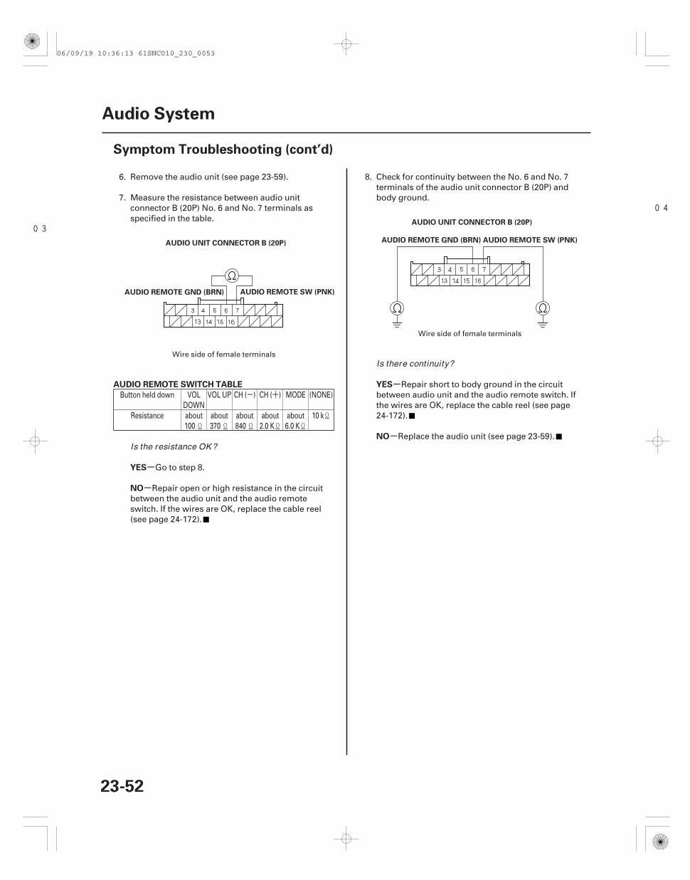
- +
03
04
-
-
-
-
AUDIO REMOTE SWITCH TABLE
YES
NO
YES
NO
23-52
Audio System
Symptom Troubleshooting (cont’d)
AUDIO UNIT CONNECTOR B (20P)
AUDIO REMOTE SW (PNK)AUDIO REMOTE GND (BRN)
AUDIO UNIT CONNECTOR B (20P)
AUDIO REMOTE SW (PNK)AUDIO REMOTE GND (BRN)
6. Remove the audio unit (see page 23-59).
7. Measure the resistance between audio unitconnector B (20P) No. 6 and No. 7 terminals asspecified in the table.
Go to step 8.
Repair open or high resistance in the circuitbetween the audio unit and the audio remoteswitch. If the wires are OK, replace the cable reel(see page 24-172).
8. Check for continuity between the No. 6 and No. 7terminals of the audio unit connector B (20P) andbody ground.
Repair short to body ground in the circuitbetween audio unit and the audio remote switch. Ifthe wires are OK, replace the cable reel (see page24-172).
Replace the audio unit (see page 23-59).
Button held down VOLDOWN
VOL UP CH ( ) CH ( ) MODE (NONE)
Resistance about100
about370
about840
about2.0 K
about6.0 K
10 k
Wire side of female terminals
Wire side of female terminals
Is the resistance OK ?
Is there continuity?
06/09/19 10:36:13 61SNC010_230_0053
SNC7AN1J10311100000FAAT28 SNC7AN1J10300000000FAAT30
-
-
-
-
Audio disc cannot be inserted and/or ejected(with navigation)
PC card will not play/card icon on audioscreen cannot be selected (with navigation)
YES
NO
YES
NO
23-5323-53
NOTE:• Disc labels should not be used in the navigation unit
or audio unit. They may damage the playermechanism.
• Make sure the CD disc is compatible with the system(see the owner’s manual for more information).
1. Press the OPEN/CLOSE button to open thenavigation display.
2. Try inserting an audio CD.
The system is OK at this time.
Go to step 3.
3. Press the CD eject button.
The system is OK at this time.
Replace the navigation unit (see page 23-122).
Unfortunately there are no error messages and nodiagnostics for the PC card. There are many reasonswhy a card won’t play audio files in the audio unit.• The card may not be fully inserted into the slot. Eject
the card, and inspect for warping or damage to theedge connector. Never use excessive force to insert acard. This can result in damage to the pins in the rearof the slot.
• The customer’s card may contain audio files that arenot recognized by the system. Only MP3 and WMAmusic files are played.
• The flash card type may not be accepted by thesystem. Only Compact Flash, SD, and ATA cards havebeen tested.
• The card’s PCMCIA adaptor may be preventing aknown-good card from playing. New PCMCIAadaptors are constantly being released, and have notbeen tested.
• The card’s capacity may exceed 1 GB. Only cardswith capacities of up to 1 GB (1000 MB) have beentested.
• There may not be any files on the card. Of the cardhas ‘‘write protection,’’ make sure it is turned offbefore putting files on the card.
• Although flash memory chips are reliable,occasionally they develop bad sectors or otherformatting errors that prevents them from playing.The customer should re-format the card using theFAT or FAT32 format.
• The card may have been damaged by heat. Suggestthat the customer remove their card when exiting thevehicle.
• The customer may have formatted the card using theNTFS format. Only the FAT and FAT32 formats areaccepted by the system.
• Hard disc drive (HDD) cards may not work properly inthe system and can overheat and quit functioning,particularly in a hot vehicle. They are notrecommended.
• The filing structure of the card may exceed thespecification of 8 folder levels deep, 99 foldersmaximum, and 999 total tracks maximum. If any ofthese limitations is exceeded, the system may notproperly display or play the tracks.
NOTE: A delay when first inserting a card is normal.The system is reading the ‘‘File Tag’’ information foralbum names, artist, and song titles and there is no‘‘hour glass’’ The delay length depends on the numberof tracks and the complexity of the folder structure.See the audio section glossary for an explanation of theterms used above.
Does the player except the CD?
Does the player eject the CD?
06/09/19 10:36:13 61SNC010_230_0054
SNC7A00J10300000000FEAT01 SNC7A00J10300000000FEAT02
Special Tools Required Special Tools Required
Left/Right Channel ID
Phase Test
23-5423-54
Audio System
Sound Quality Diagnosis
Diagnostics CD 07AAZ-SDBA100
Use the following tests to check sound quality.
NOTE: Before beginning the following tests, write downthe bass, treble, fader and balance settings, and thenset them to their center positions for testing.
Do this test to confirm proper channel routing.
1. Insert the audio diagnostic CD (T/N 07AAZ-SDBA100) into the navigation unit or audio unit.
2. Play track No. 1 (left, both, right channel ID) at anormal, or slightly higher than normal, volumelevel.
3. The voice should be audible only from the channelor channels when indicated.
• If the channel ID is correct for each side, go to thephase test.
• If the channel ID is not correct, check for;– Shorted speaker wire– Faulty navigation unit– Faulty audio unit
Diagnostics CD 07AAZ-SDBA100
Do this test to confirm proper speaker phasing.
1. Insert the audio diagnostic CD (T/N 07AAZ-SDBA100) into the navigation unit or audio unit.
2. Play track No. 2 (phase) at a normal, or slightlyhigher than normal, volume level.
3. The voice should sound centered and focusedwhen it is in-phase.
4. The voice should sound diffused, and have ‘‘lessbass’’ when it is out of phase.
• If the voice changes from in-phase to out ofphase as indicated by the prompt, the phasing iscorrect. Go to electrical noise test.
• If the voice always sounds out of phase, phasingis not correct. Check for;– Crossed speaker wires– Faulty navigation unit– Faulty audio unit
06/09/19 10:36:14 61SNC010_230_0055
SNC7A00J10300000000FEAT00
Special Tools Required
Electrical Noise Test
23-55
Diagnostics CD 07AAZ-SDBA100
Do this test to check for electrical noise being inducedinto the audio system.
NOTE: Electrical noise may be caused by outsidesources that cannot be prevented by the audio system.Make sure you remove any cell phones and/or turn offany aftermarket device before beginning this test.
1. Insert the audio diagnostic CD (T/N 07AAZ-SDBA100) into the navigation unit or audio unit.
2. Play track No. 4 (digital zero) at a normal, or slightlyhigher than normal, volume level.
3. Operate any electrical device that may createelectrical noise in the audio system, includingstarting the engine.
4. Play track No. 5 (near digital zero) at a normal, orslightly higher than normal, volume level.
5. Operate any electrical device that may createelectrical noise in the audio system, includingstarting the engine.
6. Play track No. 6 (SNR) at a normal, or slightlyhigher than normal, volume level.
7. Operate any electrical device that may createelectrical noise in the audio system, includingstarting the engine.
• If no abnormal noise is heard, go to individualspeaker test.
• If the noise is present only during the SNR track,replace the navigation unit or audio unit.
• If the noise is heard during the digital zero ornear digital zero track, check for;– Poor ground for the audio unit, engine or
battery cable– Pinched or shorted speaker wire– Faulty navigation unit– Faulty audio unit– Other faulty components causing excessive
electrical noise (ignition coils, alternator, doorlock actuators, etc.). Disconnect any suspectcomponents, and then replay the tracks thatwere originally noisy. If the noise is gone,check the component’s circuit and thecomponent.
06/09/19 10:36:14 61SNC010_230_0056
SNC7A00J10300000000FEAT11 SNC7A00J10300000000FEAT63
Special Tools Required Special Tools Required
Individual Speaker Test Sound Balance Test
23-5623-56
Audio System
Sound Quality Diagnosis (cont’d)
Diagnostics CD 07AAZ-SDBA100
Do this test to identify a faulty speaker.
1. Insert the audio diagnostic CD (T/N 07AAZ-SDBA100) into the navigation unit or audio unit.
2. Play track No. 30 (steady 300 Hz tone) at a normal,or slightly higher than normal, volume level.
3. Listen to each speaker for poor sound compared tothe other speakers. Use the audio unit’s fader andbalance settings to help isolate the channel with theproblem.
• If the sound quality produced by a specificspeaker is poor, substitute it with a known-goodspeaker. If the poor sound quality continues, goto the sound balance test.
• If the sound quality is OK, go to the soundbalance test.
Diagnostics CD 07AAZ-SDBA100
Perform this test to identify a faulty channel or speaker.
1. Insert the audio diagnostic CD (T/N 07AAZ-SDBA100) into the navigation unit or audio unit.
2. Confirm the bass and treble are set to the centerpositions.
3. Play track No. 3 (pink noise) at a normal, or slightlyhigher then normal, volume level.
4. A ‘‘static’’ type sound should be heard through allspeakers.
5. Insert the audio diagnostic CD (T/N 07AAZ-SDBA100) into the navigation unit or audio unit of aknown-good vehicle.
6. Set the bass and treble to the center position.
7. Play track No. 3 (pink noise) all the same level aswas played in step 3.
8. Compare the sounds made by the two vehicles.
• If the sounds made by the two vehicles are verysimilar, go to the Frequency Sweep Test(see page 23-57).
• If the sound does not have as much bass, checkthe subwoofer and circuit.
• If the sound does not have enough ‘‘hiss,’’ checkthe tweeters and their circuits.
06/09/19 10:36:14 61SNC010_230_0057
SNC7A00J10300000000FEAT21 SNC7A00J10300000000FEAT62
Special Tools Required Special Tools Required
Frequency sweep Sound judging
23-5723-57
Diagnostics CD 07AAZ-SDBA100
Do this test to find rattles or reverberations that maycause a perception of poor sound quality.
1. Insert the audio diagnostic CD (T/N 07AAZ-SDBA100) into the navigation unit or audio unit.
2. Play track No. 13 (sweep from 500 Hz to 35 Hz) at anormal, or slightly higher than normal, volumelevel.
3. Listen to each speaker for poor sound quality orreverberations caused by specific frequencies. Usethe voice-over to estimate the frequency thatcauses the vibration. Use the audio unit’s fader andbalance settings to help isolate the channel with theproblem.
• If vibrations or poor sound quality are heard, goto step 4.
• If no vibrations or poor sound quality are heard,go to sound judging.
4. Choose the appropriate track from No. 14 to 25(small range frequency sweep) or 26 to 53 (singlefrequencies) to recreate the frequency that causedthe poor sound quality or vibration located in step3: this aids in diagnosis of the cause.
NOTE: When you get to the track that recreates theproblem, select the repeat function on thenavigation unit or audio unit, this will help youisolate the cause.
5. Replace or insulate the source of the vibrations or,if the speaker is the source of the poor soundquality, replace it.
Diagnostics CD 07AAZ-SDBA100
• Do this test to compare overall sound quality,imaging, and dynamics between the customer’svehicle and a known-good vehicle. Only use a vehicleof the same model and trim level for this test.
• Make sure the vehicle is using only OEM speakers.
1. In the customer vehicle, set the bass, treble, fader,and balance settings to the customer’s normalsettings that were written down before beginningtesting.
2. Insert the audio diagnostic CD (T/N 07AAZ-SDBA100) into the navigation unit or audio unit.
3. Play tracks No. 7 to 12 (sound quality, midland,dynamics, and imaging demonstration tracks) at anormal, or slightly higher than normal, volumelevel. Write down the volume setting being used.
4. Listen to areas of the track that stand out as beingeither very clear or poorer than other areas of thetrack.
5. Insert the audio diagnostic CD (T/N 07AAZ-SDBA100) into the navigation unit or audio unit of aknown-good vehicle.
6. Play the tracks at the same volume level and thesame bass, treble, balance, and fader settings asused in step 3 in the customer’s vehicle.
7. Listen to the same area of the track that stood outas being either very clear or poorer than otherareas of the track.
(cont’d)
06/09/19 10:36:14 61SNC010_230_0058
+
+
+
+
SNC7A00J10300000000FEAT08
Seek Stop Test
23-5823-58
Audio System
Sound Quality Diagnosis (cont’d)
8. Compare the customer vehicle’s sound qualityresults to the known-good vehicle’s results.
• If the sound quality in the customer vehicle iscomparable to the sound quality in the known-good vehicle, then the customer’s vehicle isoperating as designed.
• If the sound quality is not comparable, checkthese items in order.– Loose or improperly installed speakers or
other hardware that may become excited bythe vibrations generated by the speakers
– Damaged speaker(s)– Faulty navigation unit– Faulty audio unit
Do this test to check the performance of the audio unit’sAM and FM reception. Refer to symptomtroubleshooting: audio sound weak or distorted, or nosound is heard from speakers (display is normal)(see page 23-32) before continuing with this test.
NOTE:• Window tint, aftermarket theft-recovery devices and
other aftermarket accessories may reduce radioreception.
• Changes in cloud cover and other atmosphereconditions will affect the ability of the navigation unitor audio unit to receive radio signals.
1. Park the customer’s vehicle in an open area awayfrom buildings or other obstructions.
2. Park a known-good vehicle (same year, model, andtrim level) next to the customer’s vehicle, facing thesame direction.
3. Start the engine in the customer’s vehicle, and turnon the radio.
4. Set the FM receiver to 87.7 MHz.
5. Press the ‘‘Seek ’’ button and record the firststation that the navigation unit or audio unit locksonto.
6. Press the ‘‘Seek ’’ button repeatedly, and writedown each station that the navigation unit or audiounit locks onto until the station recorded in step 5 isreached again.
7. Set the AM receiver to 530 kHz.
8. Press the ’’Seek ’’ button, and record the firststation that the navigation unit or audio unit lockson to.
9. Press the ’’Seek ’’ button repeatedly, and writedown each station that the navigation unit or audiounit locks onto until the station recorded in step 8 isreached again.
06/09/19 10:36:14 61SNC010_230_0059
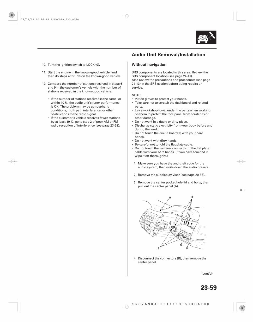
01
SNC7AN0J10311113151KDAT00
Without navigation
23-5923-59
Audio Unit Removal/Installation
A B
B
10. Turn the ignition switch to LOCK (0).
11. Start the engine in the known-good vehicle, andthen do steps 4 thru 10 on the known-good vehicle.
12. Compare the number of stations received in steps 6and 9 in the customer’s vehicle with the number ofstations received in the known-good vehicle.
• If the number of stations received is the same, orwithin 10 %, the audio unit’s tuner performanceis OK. The problem may be atmosphericconditions, multi path interference, or otherobstructions to the radio signal.
• If the customer’s vehicle receives fewer stationsby at least 10 %, go to step 2 of poor AM or FMradio reception of interference (see page 23-23).
SRS components are located in this area. Review theSRS component location (see page 24-11).Also review the precautions and procedures (see page24-13) in the SRS section before doing repairs orservice.
NOTE:• Put on gloves to protect your hands.• Take care not to scratch the dashboard and related
parts.• Lay a workshop towel under the parts when working
on them to protect the face panel from scratches orother damage.
• Do not work in a dusty or dirty place.• Discharge static electricity from your body before and
during the work.• Do not touch the circuit board(s) with your bare
hands.• Do not work with dirty hands.• Be careful not to fold the flat plate cable.• Do not touch the terminal connector of the flat plate
cable with your bare hands. (If you have touched it,wipe it off thoroughly.)
1. Make sure you have the anti-theft code for theaudio system, then write down the audio presets.
2. Remove the subdisplay visor (see page 20-86).
3. Remove the center pocket hole lid and bolts, thenpull out the center panel (A).
4. Disconnect the connectors (B), then remove thecenter panel.
(cont’d)
06/09/19 10:36:15 61SNC010_230_0060
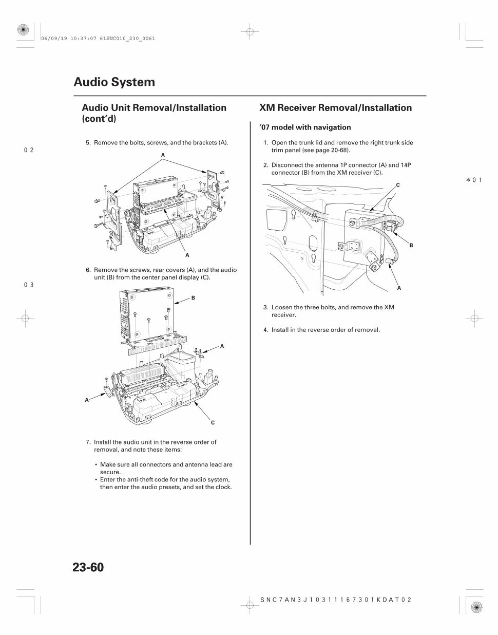
02
03
*01
SNC7AN3J10311167301KDAT02
’07 model with navigation
23-6023-60
Audio System
Audio Unit Removal/Installation(cont’d)
XM Receiver Removal/Installation
A
A
A
B
A
C
A
B
C
5. Remove the bolts, screws, and the brackets (A).
6. Remove the screws, rear covers (A), and the audiounit (B) from the center panel display (C).
7. Install the audio unit in the reverse order ofremoval, and note these items:
• Make sure all connectors and antenna lead aresecure.
• Enter the anti-theft code for the audio system,then enter the audio presets, and set the clock.
1. Open the trunk lid and remove the right trunk sidetrim panel (see page 20-68).
2. Disconnect the antenna 1P connector (A) and 14Pconnector (B) from the XM receiver (C).
3. Loosen the three bolts, and remove the XMreceiver.
4. Install in the reverse order of removal.
06/09/19 10:37:07 61SNC010_230_0061
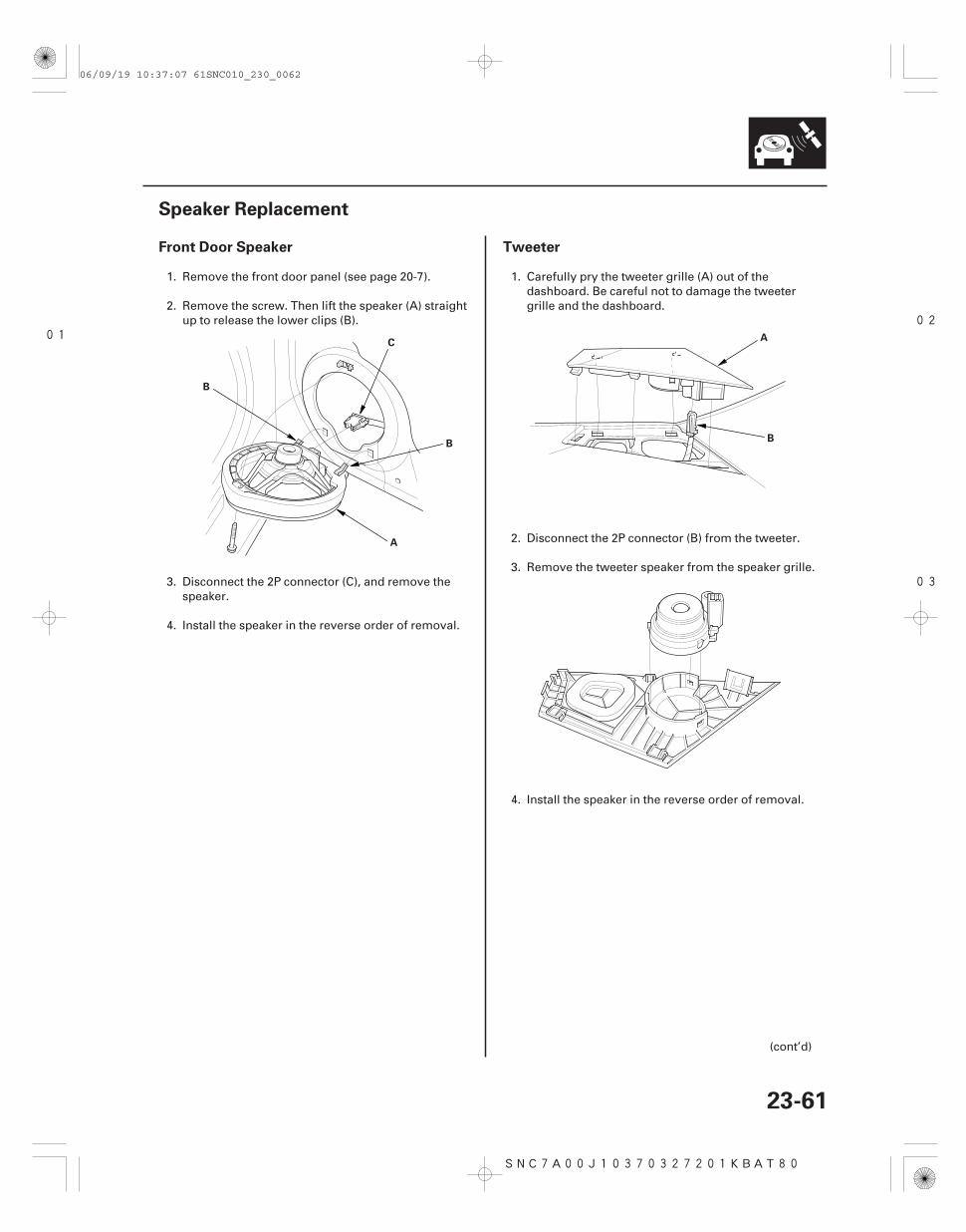
0102
03
SNC7A00J10370327201KBAT80
Front Door Speaker Tweeter
23-61
Speaker Replacement
A
B
C
B
A
B
1. Remove the front door panel (see page 20-7).
2. Remove the screw. Then lift the speaker (A) straightup to release the lower clips (B).
3. Disconnect the 2P connector (C), and remove thespeaker.
4. Install the speaker in the reverse order of removal.
1. Carefully pry the tweeter grille (A) out of thedashboard. Be careful not to damage the tweetergrille and the dashboard.
2. Disconnect the 2P connector (B) from the tweeter.
3. Remove the tweeter speaker from the speaker grille.
4. Install the speaker in the reverse order of removal.
(cont’d)
06/09/19 10:37:07 61SNC010_230_0062
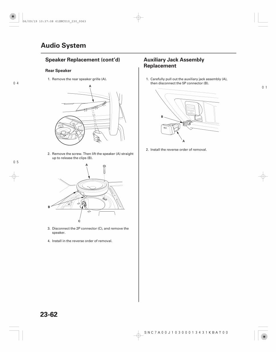
04
05
01
SNC7A00J10300013431KBAT00
Rear Speaker
23-6223-62
Audio System
Speaker Replacement (cont’d) Auxiliary Jack AssemblyReplacement
A
A
C
B
A
B
1. Remove the rear speaker grille (A).
2. Remove the screw. Then lift the speaker (A) straightup to release the clips (B).
3. Disconnect the 2P connector (C), and remove thespeaker.
4. Install in the reverse order of removal.
1. Carefully pull out the auxiliary jack assembly (A),then disconnect the 5P connector (B).
2. Install the reverse order of removal.
06/09/19 10:37:08 61SNC010_230_0063
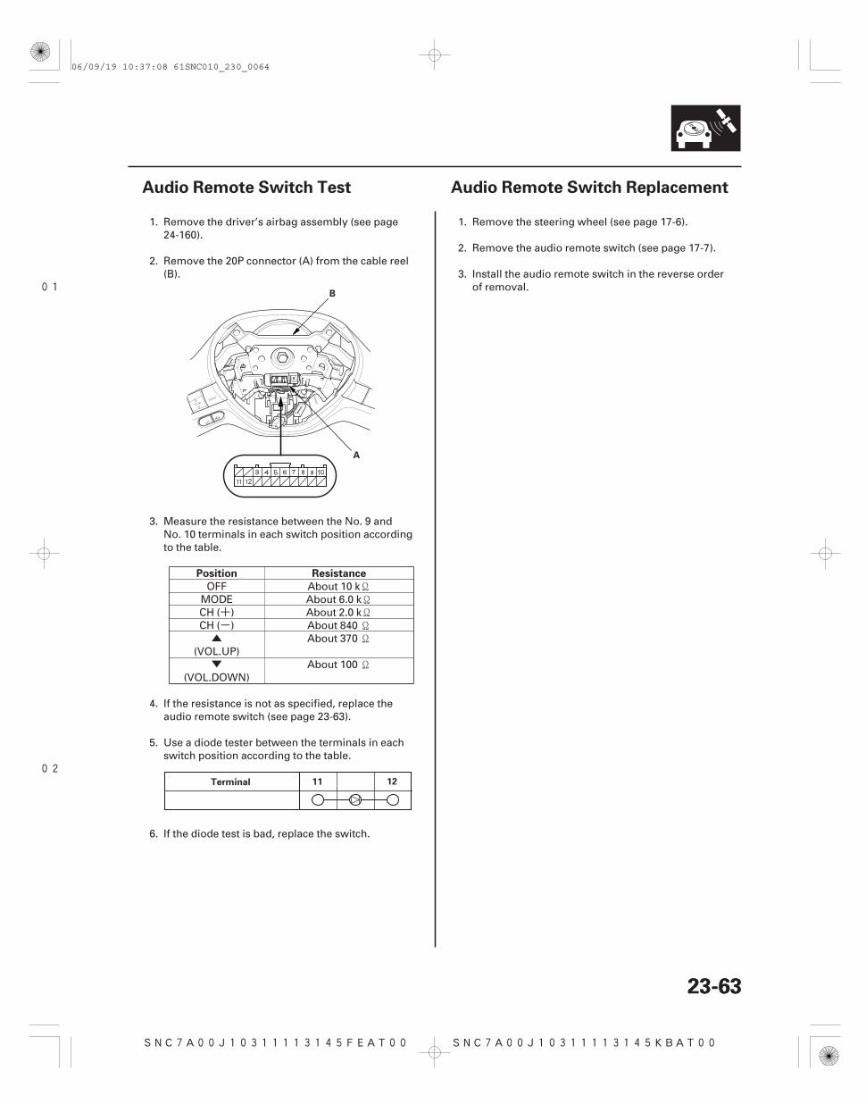
+-▲
▼
01
02
SNC7A00J10311113145FEAT00 SNC7A00J10311113145KBAT00
Position Resistance
23-6323-63
Audio Remote Switch Test Audio Remote Switch Replacement
A
B
Terminal 11 12
1. Remove the driver’s airbag assembly (see page24-160).
2. Remove the 20P connector (A) from the cable reel(B).
3. Measure the resistance between the No. 9 andNo. 10 terminals in each switch position accordingto the table.
OFF About 10 kMODE About 6.0 kCH ( ) About 2.0 kCH ( ) About 840
(VOL.UP)About 370
(VOL.DOWN)About 100
4. If the resistance is not as specified, replace theaudio remote switch (see page 23-63).
5. Use a diode tester between the terminals in eachswitch position according to the table.
6. If the diode test is bad, replace the switch.
1. Remove the steering wheel (see page 17-6).
2. Remove the audio remote switch (see page 17-7).
3. Install the audio remote switch in the reverse orderof removal.
06/09/19 10:37:08 61SNC010_230_0064
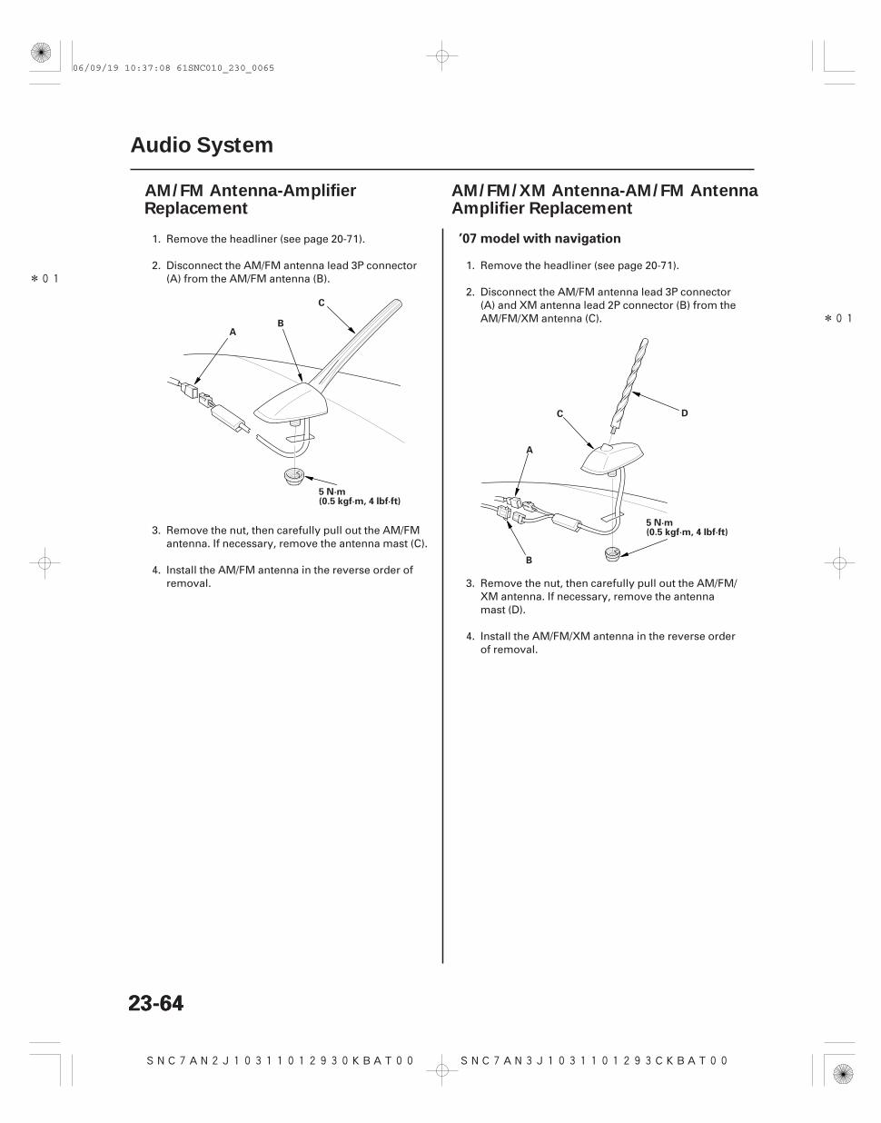
*01
SNC7AN2J10311012930KBAT00
*01
SNC7AN3J1031101293CKBAT00
’07 model with navigation
23-6423-64
Audio System
AM/FM Antenna-AmplifierReplacement
AM/FM/XM Antenna-AM/FM Antenna Amplifier Replacement
AB
5 N·m(0.5 kgf·m, 4 lbf·ft)
C
5 N·m(0.5 kgf·m, 4 lbf·ft)
A
B
C D
1. Remove the headliner (see page 20-71).
2. Disconnect the AM/FM antenna lead 3P connector(A) from the AM/FM antenna (B).
3. Remove the nut, then carefully pull out the AM/FMantenna. If necessary, remove the antenna mast (C).
4. Install the AM/FM antenna in the reverse order ofremoval.
1. Remove the headliner (see page 20-71).
2. Disconnect the AM/FM antenna lead 3P connector(A) and XM antenna lead 2P connector (B) from theAM/FM/XM antenna (C).
3. Remove the nut, then carefully pull out the AM/FM/XM antenna. If necessary, remove the antennamast (D).
4. Install the AM/FM/XM antenna in the reverse orderof removal.
06/09/19 10:37:08 61SNC010_230_0065
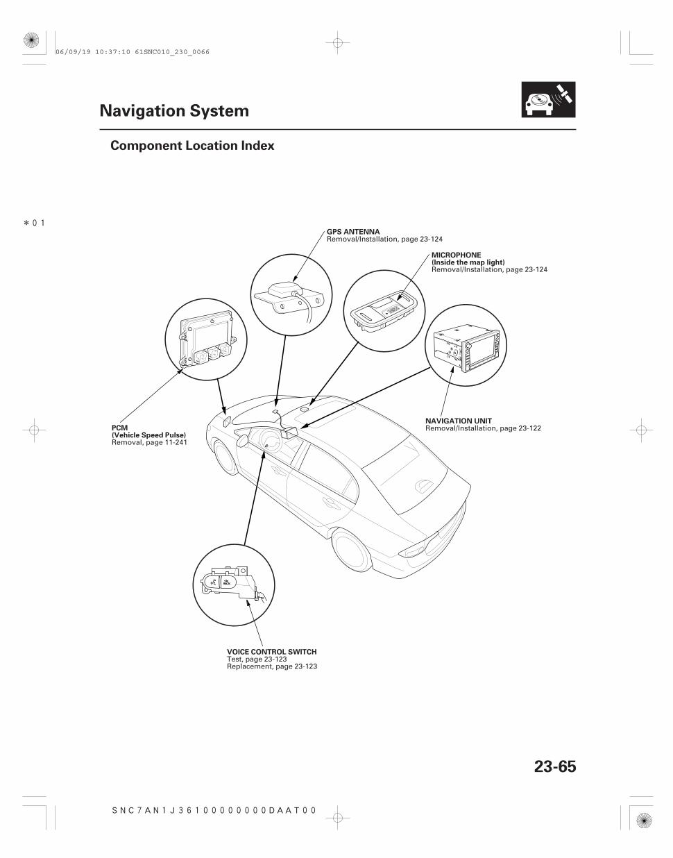
*01
SNC7AN1J36100000000DAAT00
23-65
Navigation System
Component Location Index
PCM(Vehicle Speed Pulse)
GPS ANTENNA
MICROPHONE(Inside the map light)
NAVIGATION UNIT
VOICE CONTROL SWITCH
Removal, page 11-241
Removal/Installation, page 23-124
Removal/Installation, page 23-124
Removal/Installation, page 23-122
Test, page 23-123Replacement, page 23-123
06/09/19 10:37:10 61SNC010_230_0066
SNC7AN1J36100000000BBAT00
General Operation
Anti-theft Feature
Symptom Diagnosis
Self-Inertial Navigation Limitations
Global Positioning System (GPS) Limitations
23-66
Navigation System
General Troubleshooting Information
Refer to the Honda Navigation System manual, for thenavigation system operating procedures.
The navigation system has a coded theft protectioncircuit. Make sure you have the customer’s anti-theftsecurity code before;
• Disconnecting the battery• Disconnecting the navigation unit 12P and 17P
connector• Removing the No. 23 (10 A) fuse from the under-hood
fuse/relay box
After service, reconnect power to the navigation unit,and turn the ignition switch ON (II). Enter the 4-digitanti-theft security codes, then select ‘‘Done.’’
When replacing the navigation unit, be sure to give thecustomer the new anti-theft security code.
Certain circumstances and system limitations will resultin occasional vehicle positioning errors. Somecustomers may think this indicates a problem with thenavigation system when, in fact, the system is normal.Keep the following items in mind when interviewingcustomers about symptoms of the navigation system.
The limitations of the self-inertial portion of thenavigation system (the yaw rate sensor and the vehiclespeed signal) can cause some discrepancies betweenthe vehicle’s actual position and the indicated vehicleposition (GPS vehicle position).
The following circumstances may cause vehiclepositioning errors:
• Moving the vehicle with the engine stopped and thevehicle stopped, such as by ferry or tow truck, or ifthe vehicle is spun on a turn table.
• Tire slippage, changes in tire rolling diameters, andsome driving situations may cause discrepancies intravel distances. Examples of this include:– Continuous tire slippage on a slippery surface.– Driving with snow chains mounted.– Abnormal tire pressure.– Incorrect tire size.– Frequent lane changes across a wide highway.
– Continuous driving on a straight or gently curvinghighway.
• Tolerances in the system and map inaccuracies willsometimes limit how precisely the vehicle position isindicated. Examples of this include:– Driving on roads not shown on the map (map
matching is not possible).– Driving on a road that winds in one direction, such
as a loop bridge, an interchange, or a spiral parkinggarage.
– Driving on a road with a series of sharp hair-pinturns.
– Driving near a gradual highway exit or transition.– Driving on one of two close parallel roads.– Making many 90 degree turns.– The direction to destination icon or ‘‘Destination
icon’’ shown or the map may be up to severalhundred feet away from the actual location.
The GPS cannot detect the vehicle’s position during thefollowing conditions:
• For the first 5 to 10 minutes after reconnecting thebattery (this can take as long as 45 minutes).
• When the satellite signals are blocked by tallbuildings, mountains, tunnels, large trees, or largetrucks.
• When the GPS antenna is blocked by an object placedabove it in the vehicle. The GPS antenna requires aclear unobstructed view of the sky.
• When the satellite signals are blocked by theoperation of some electronic aftermarket accessoriesincluding, but not limited to non-OEM in-dashentertainment units (radio, CD players/changers, andLo Jack), cell phones placed near navigation systemand window tinting above the GPS antenna.
The accuracy of GPS is reduced during these instances:
• When only three satellite signals can be received(Four satellite signals are required for accuratepositioning).
• When the satellite control centers are experiencingproblems.
• When driving near high tension power lines.
06/09/19 10:37:10 61SNC010_230_0067
Muting Logic
LCD Unit Limitations
Symptom Duplication
Service Precautions
System Initialization
Entering Security Code
23-67
Whenever the navigation system is giving guidance,the front speakers are muted. When the voice controlsystem is being used, all of the speakers are muted.
• In cold temperatures, the display may stay dark forthe first 2 or 3 minutes until it warms up.
• When the display is too hot because of direct summersunlight, it will remain dark until the temperaturedrops.
• When the humidity is high and the interiortemperature is low, the display may appear cloudy.The display will clear up after some use.
• Fingerprints on the touch panel may sometimes benoticeable because of the panel’s low-reflectioncoating. Clean the screen with a soft damp cloth. Youmay use a mild cleaner intended for eye glasses orcomputer screens. To avoid scratching the panel, donot rub too hard, or use abrasive cleaners, or shoptowels.
• The touch panel uses a resistive membrane, that isunaffected by sunlight. If a touch switch does notfunction immediately, shift your finger slightly, andtouch it again.
• If you can duplicate the symptom, compare it to a‘‘similar known-good vehicle. ’’Only use a vehicle ofthe same model, same year, same trim, and samesoftware version. If you can duplicate the symptom inthe like known-good vehicle, then it is a characteristicof the system.
• When the symptom can be duplicated, follow the self-diagnostic procedures and the appropriatetroubleshooting procedures.
• When the symptom does not reappear or onlyreappears intermittently, ask the customer about theconditions when the symptom occurred.– Try to establish if outside interference may be the
cause.– Try to duplicate the symptom under the same
conditions the customer experienced.– Vibration, temperature extremes, and moisture
(dew, humidity) are factors that are difficult toduplicate.
– Inspect the vehicle for aftermarket electronicdevices (vehicle locators, radar detector amps, etc.)that may be hidden.
• Check for service bulletins or Service News articlesthat may relate to the customer’s concern.
• Before disconnecting the battery, make sure youhave the anti-theft code for the navigation system,and write down the audio presets.
• The navigation unit is located in the dashboard.• When the battery is disconnected, the internal GPS
clock is reset to ‘‘0:00.’’ The clock will reset to thecorrect time after the system finishes the GPSinitialization.
• After reconnecting the battery, you have to wait to getthe initial signal from the satellite. It will take from 10to 45 minutes.
• Before returning the vehicle to the customer, enterthe navigation anti-theft security code, then enter theaudio station presets.
If for any reason, you lose power to the navigationsystem (like the battery was disconnected), thenavigation system will require initialization. Oncecompleted, your system will be ready to use.
This initialization requires the following:• Entering the 4-digit navigation anti-theft security code
to ‘‘unlock’’ the system• GPS initialization (may not be needed depending on
the length of time the system was without power)• Map matching to align the GPS to a location on the
map
The navigation system has a coded theft protectioncircuit. Be sure to get the customer’s anti-theft securitycodes number before;• Disconnecting the battery• Disconnecting the navigation unit 17P connector• Removing the No. 23 (10 A) fuse from the under-hood
fuse/relay box
After service, reconnect power to the navigation unit,and turn the ignition switch ON (II). Enter the 4-digitanti-theft security code, then select ‘‘Done.’’When replacing the navigation unit or audio unit, besure to give the customer the new anti-theft securitycode.
(cont’d)
06/09/19 10:37:11 61SNC010_230_0068
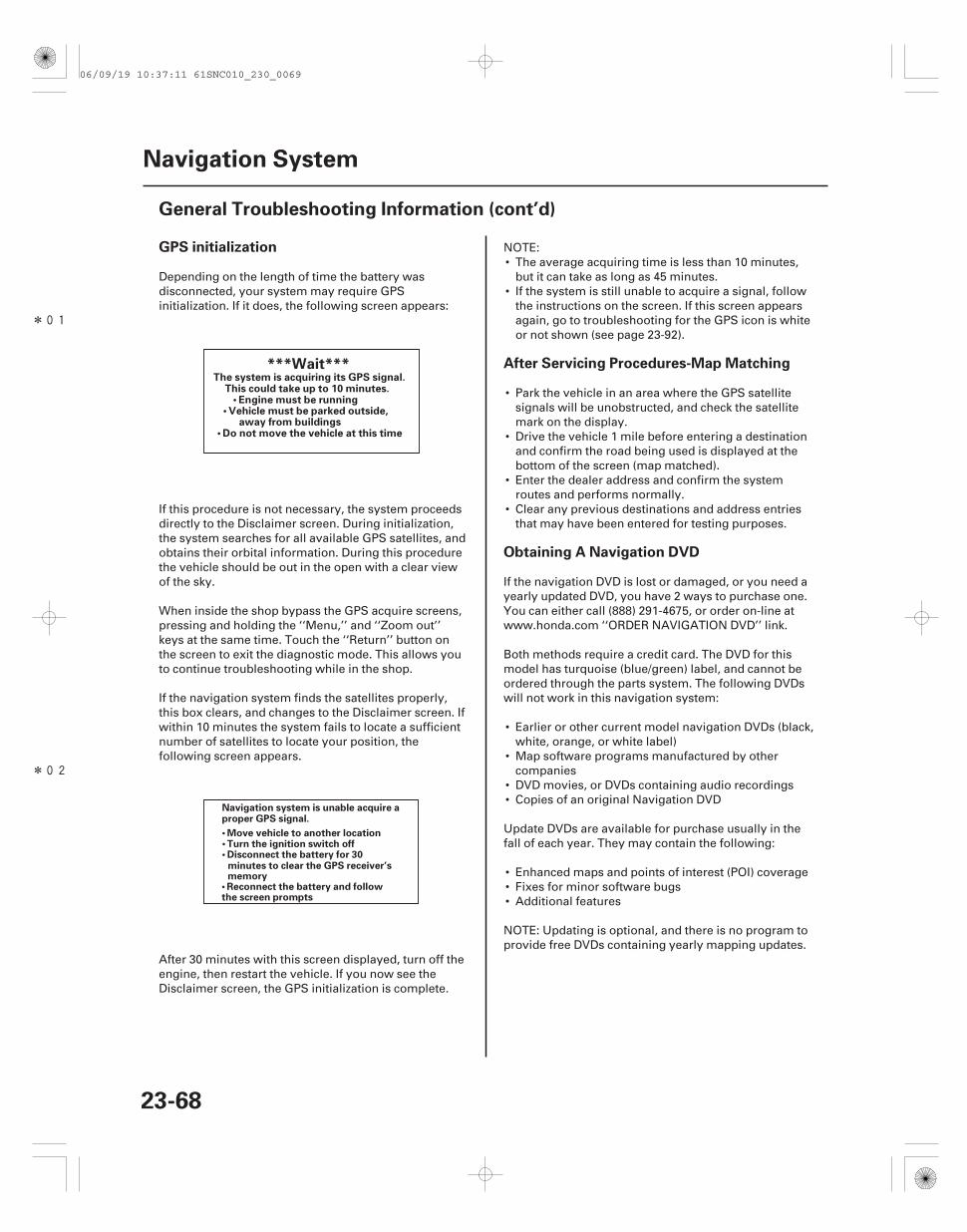
*01
*02
GPS initialization
After Servicing Procedures-Map Matching
Obtaining A Navigation DVD
23-68
Navigation System
General Troubleshooting Information (cont’d)
The system is acquiring its GPS signal.This could take up to 10 minutes.
• Engine must be running• Vehicle must be parked outside,
away from buildings• Do not move the vehicle at this time
***Wait***
Navigation system is unable acquire a
• Move vehicle to another location• Turn the ignition switch off• Disconnect the battery for 30
minutes to clear the GPS receiver’smemory
• Reconnect the battery and followthe screen prompts
proper GPS signal.
Depending on the length of time the battery wasdisconnected, your system may require GPSinitialization. If it does, the following screen appears:
If this procedure is not necessary, the system proceedsdirectly to the Disclaimer screen. During initialization,the system searches for all available GPS satellites, andobtains their orbital information. During this procedurethe vehicle should be out in the open with a clear viewof the sky.
When inside the shop bypass the GPS acquire screens,pressing and holding the ‘‘Menu,’’ and ‘‘Zoom out’’keys at the same time. Touch the ‘‘Return’’ button onthe screen to exit the diagnostic mode. This allows youto continue troubleshooting while in the shop.
If the navigation system finds the satellites properly,this box clears, and changes to the Disclaimer screen. Ifwithin 10 minutes the system fails to locate a sufficientnumber of satellites to locate your position, thefollowing screen appears.
After 30 minutes with this screen displayed, turn off theengine, then restart the vehicle. If you now see theDisclaimer screen, the GPS initialization is complete.
NOTE:• The average acquiring time is less than 10 minutes,
but it can take as long as 45 minutes.• If the system is still unable to acquire a signal, follow
the instructions on the screen. If this screen appearsagain, go to troubleshooting for the GPS icon is whiteor not shown (see page 23-92).
• Park the vehicle in an area where the GPS satellitesignals will be unobstructed, and check the satellitemark on the display.
• Drive the vehicle 1 mile before entering a destinationand confirm the road being used is displayed at thebottom of the screen (map matched).
• Enter the dealer address and confirm the systemroutes and performs normally.
• Clear any previous destinations and address entriesthat may have been entered for testing purposes.
If the navigation DVD is lost or damaged, or you need ayearly updated DVD, you have 2 ways to purchase one.You can either call (888) 291-4675, or order on-line atwww.honda.com ‘‘ORDER NAVIGATION DVD’’ link.
Both methods require a credit card. The DVD for thismodel has turquoise (blue/green) label, and cannot beordered through the parts system. The following DVDswill not work in this navigation system:
• Earlier or other current model navigation DVDs (black,white, orange, or white label)
• Map software programs manufactured by othercompanies
• DVD movies, or DVDs containing audio recordings• Copies of an original Navigation DVD
Update DVDs are available for purchase usually in thefall of each year. They may contain the following:
• Enhanced maps and points of interest (POI) coverage• Fixes for minor software bugs• Additional features
NOTE: Updating is optional, and there is no program toprovide free DVDs containing yearly mapping updates.
06/09/19 10:37:11 61SNC010_230_0069
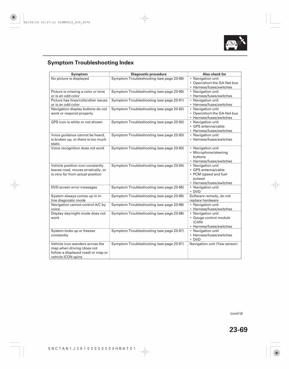
SNC7AN1J36100000000HBAT01
Symptom Diagnostic procedure Also check for
23-69
Symptom Troubleshooting Index
•••••••••••••••
••
••••
•••
••••
••••
No picture is displayed Symptom Troubleshooting (see page 23-89) Navigation unitOpen/short the GA-Net busHarness/fuses/switches
Picture is missing a color or toneor is an odd color
Symptom Troubleshooting (see page 23-90) Navigation unitHarness/fuses/switches
Picture has lines/rolls/other issuesor is an odd color
Symptom Troubleshooting (see page 23-91) Navigation unitHarness/fuses/switches
Navigation display buttons do notwork or respond properly
Symptom Troubleshooting (see page 23-92) Navigation unitOpen/short the GA-Net busHarness/fuses/switches
GPS icon is white or not shown Symptom Troubleshooting (see page 23-92) Navigation unitGPS antenna/cableHarness/fuses/switches
Voice guidance cannot be heard,is broken up, or there is too muchstatic
Symptom Troubleshooting (see page 23-93) Navigation unitHarness/fuses/switches
Voice recognition does not work Symptom Troubleshooting (see page 23-93) Navigation unitMicrophone/steeringbuttonsHarness/fuses/switches
Vehicle position icon constantlyleaves road, moves erratically, oris very far from actual position
Symptom Troubleshooting (see page 23-94) Navigation unitGPS antenna/cablePCM (speed and fuelpulses)Harness/fuses/switches
DVD screen error messages Symptom Troubleshooting (see page 23-95) Navigation unitDVD
System always comes up in in-line diagnostic mode
Symptom Troubleshooting (see page 23-95) Software remedy, do notreplace hardware
Navigation cannot control A/C byvoice
Symptom Troubleshooting (see page 23-96) Navigation unitHarness/fuses/switches
Display day/night mode does notwork
Symptom Troubleshooting (see page 23-96) Navigation unitGauge control module(CAN)Harness/fuses/switches
System locks up or freezesconstantly
Symptom Troubleshooting (see page 23-97) Navigation unitHarness/fuses/switchesDVD
Vehicle icon wanders across themap when driving (does notfollow a displayed road) or map orvehicle ICON spins
Symptom Troubleshooting (see page 23-97) Navigation unit (Yaw sensor)
(cont’d)
06/09/19 10:37:11 61SNC010_230_0070
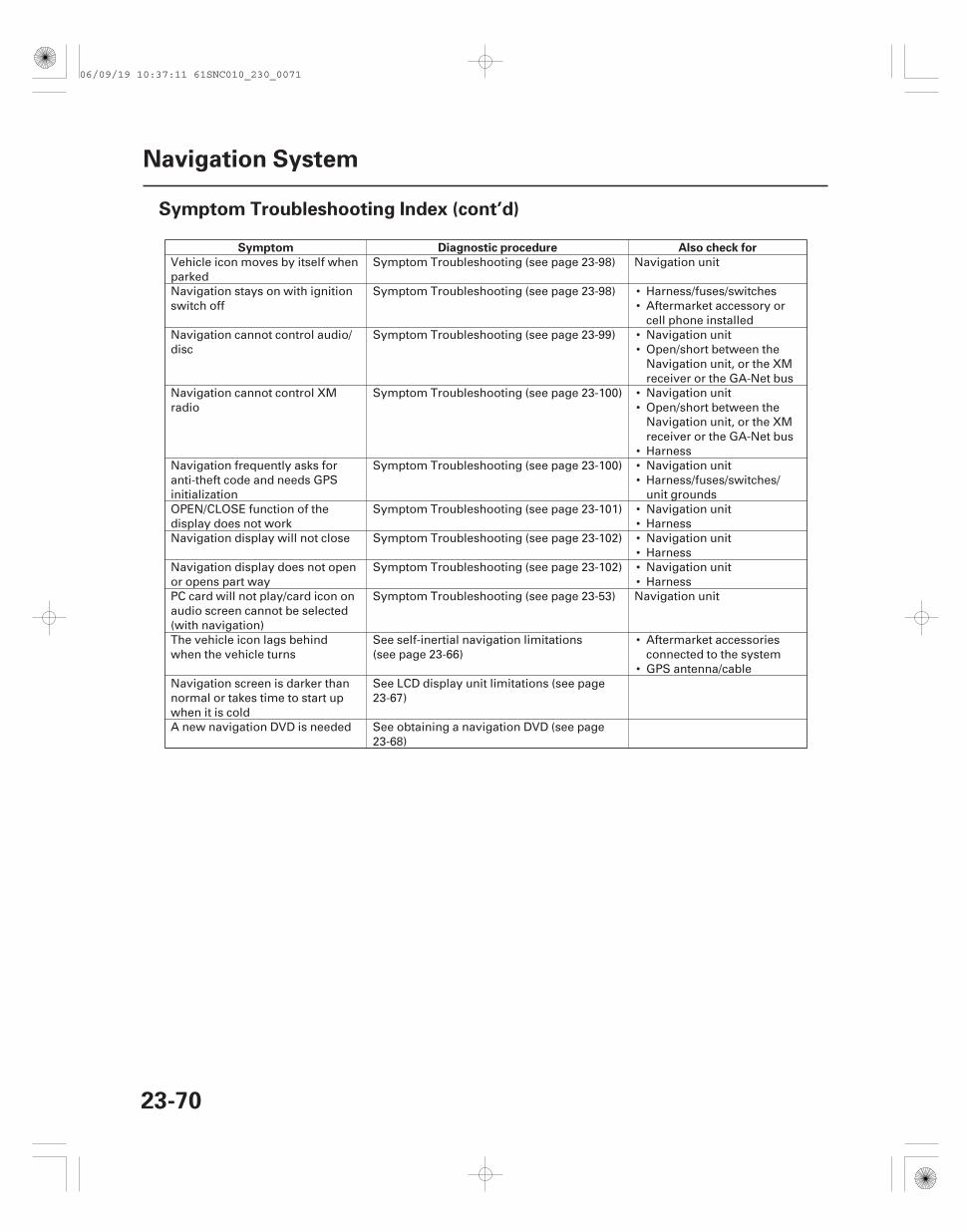
Symptom Diagnostic procedure Also check for
23-70
Navigation System
Symptom Troubleshooting Index (cont’d)
••
••
••
•••
••••••
•
•
Vehicle icon moves by itself whenparked
Symptom Troubleshooting (see page 23-98) Navigation unit
Navigation stays on with ignitionswitch off
Symptom Troubleshooting (see page 23-98) Harness/fuses/switchesAftermarket accessory orcell phone installed
Navigation cannot control audio/disc
Symptom Troubleshooting (see page 23-99) Navigation unitOpen/short between theNavigation unit, or the XMreceiver or the GA-Net bus
Navigation cannot control XMradio
Symptom Troubleshooting (see page 23-100) Navigation unitOpen/short between theNavigation unit, or the XMreceiver or the GA-Net busHarness
Navigation frequently asks foranti-theft code and needs GPSinitialization
Symptom Troubleshooting (see page 23-100) Navigation unitHarness/fuses/switches/unit grounds
OPEN/CLOSE function of thedisplay does not work
Symptom Troubleshooting (see page 23-101) Navigation unitHarness
Navigation display will not close Symptom Troubleshooting (see page 23-102) Navigation unitHarness
Navigation display does not openor opens part way
Symptom Troubleshooting (see page 23-102) Navigation unitHarness
PC card will not play/card icon onaudio screen cannot be selected(with navigation)
Symptom Troubleshooting (see page 23-53) Navigation unit
The vehicle icon lags behindwhen the vehicle turns
See self-inertial navigation limitations(see page 23-66)
Aftermarket accessoriesconnected to the systemGPS antenna/cable
Navigation screen is darker thannormal or takes time to start upwhen it is cold
See LCD display unit limitations (see page23-67)
A new navigation DVD is needed See obtaining a navigation DVD (see page23-68)
06/09/19 10:37:11 61SNC010_230_0071
SNC7AN1J36100000000CAAT00
Overview
23-71
System Description
The navigation system is a highly sophisticated, hybrid locating system.
The navigation unit uses global positioning system (GPS) satellite signals, internal yaw and vehicle speed inputs, anda map database to show where the vehicle is and to help guide you to a desired destination.
The navigation unit’s GPS receiver receives signals from the GPS, a network of 24 satellites in orbit around the earth.By receiving signals from several of these satellites, the navigation system can determine the latitude, longitude, andelevation of the vehicle.
Signals from the system’s yaw rate sensor (inside the navigation unit) detects turns, and the PCM vehicle speed pulse(VSP) and reverse signal enable the system to keep track of the vehicle’s speed and direction of travel. The advantageof this hybrid system is that the system can track your position if either the GPS signal or the vehicle speed signal ismissing. For instance, when in a tunnel (no GPS), the speed signal is used to update your position on the map.Alternately, while the vehicle is being transported on a ferry, GPS signals can show the vehicle position on the map asit crosses the water.
The navigation system uses the location, direction, and speed information to display the appropriate map andcalculate a route to the destination entered. As you drive to a destination, the system provides both visual and audioguidance. Audio guidance is sent to the audio unit, and an RGB graphics color signal is sent to the navigation display.
This navigation system also has voice recognition that allows voice control of most of the navigation, and audiofunctions. The voice control switches (TALK and BACK buttons on the steering wheel) activate the voice controlsystem. The microphone on the ceiling receives your voice commands. For more information on this feature, consultthe navigation owner’s guide.
The illumination signal is used by the navigation unit to automatically switch the display mode between the ‘‘Night’’and ‘‘Day’’ display modes. When the headlights are on, the dash brightness control setting ‘‘full brightness’’ overridesthe ‘‘Night’’ display mode, and allows a daytime navigation display with the lights on.
When the navigation system is giving voice guidance commands, the front speakers are muted. When the voicecontrol system is being used (TALK button pressed), all of the speakers are muted.
The internal GA-Net II bus passes information back and forth between the navigation display, the navigation unit, andthe audio system components. The information passed on this bus are touch button commands, audio muting signal,audio (radio and XM), and any open in these bus lines can affect the navigation system or other audio accessoryoperation.
The clock on the navigation display is set and maintained by the navigation unit. The time is automatically adjusted fordaylight savings, and time zone changes while driving. The time can be adjusted in setup.
Additional information is available about the navigation components following the System Diagram. A glossary ofterms that are used throughout this section follows the detailed information.
The Navigation System manual in the glove box covers all of the system functions and settings. Use this as a resourcewhen evaluating a customer concern.
(cont’d)
06/09/19 10:37:11 61SNC010_230_0072
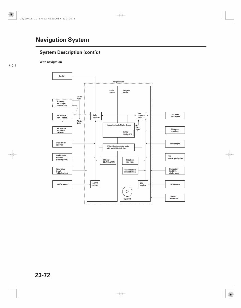
*01With navigation
23-72
Navigation System
System Description (cont’d)
Reverse signal
GPS antennaAM/FM antenna
Speakers
Navigation unit
Navi DVD
Navigation/Audio Display Screen
CLOCK(Set by GPS)
Colorsignal
Accessory(CD changer,cassette, etc.)
XM Receiver(some models)
XM antenna(satellite &terrestrial)
Auxiliary jackassembly
Audio remoteswitches(steering wheel)
IlluminationSignal(lighted buttons)
AM/FMreceiver
CD Player(CD, MP3, WMA)
Audioprocessor
PC Card Slot (for playing audioMP3, and WMA audio files)
Naviprocessor(ECU)
GPSreceiver
Yaw rate sensor(senses turning)
DVD player(navi maps)
GA-NetAudio
GA-NetAudio
AudioSection
NavigaionSection
Illumination(Night/Daydisplay mode)
PCM(vehicle speed pulses)
Microphone(on ceiling)
TALK/BACKvoice buttons
Climatecontrol unit
06/09/19 10:37:12 61SNC010_230_0073
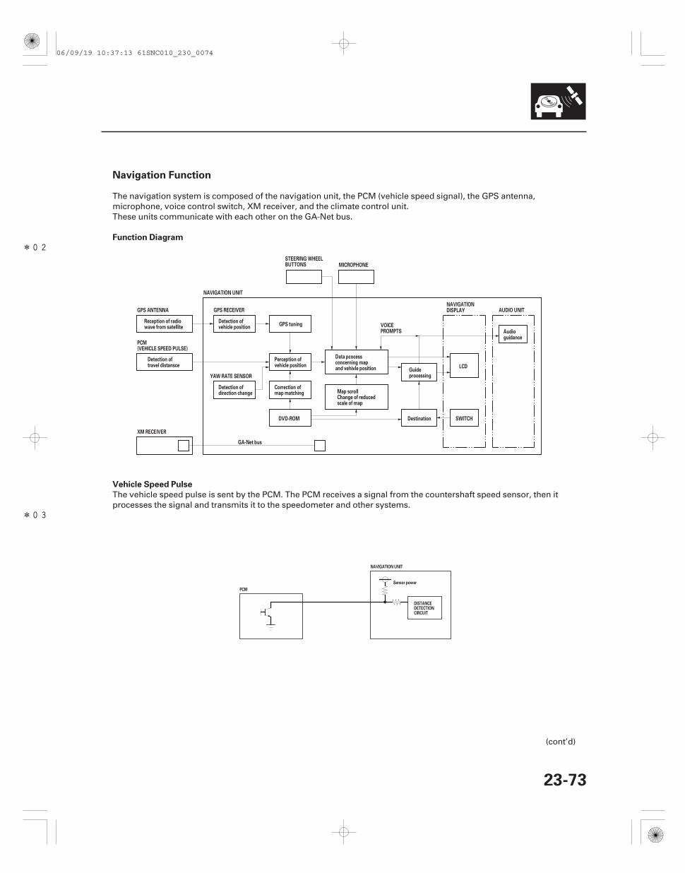
*02
*03
Navigation Function
Function Diagram
Vehicle Speed Pulse
23-73
STEERING WHEELBUTTONS MICROPHONE
GA-Net bus
AUDIO UNIT
LCD
SWITCHDestinationDVD-ROM
YAW RATE SENSOR
GPS tuning
GPS RECEIVER
NAVIGATION UNIT
XM RECEIVER
GPS ANTENNA
Reception of radiowave from satellite
Data pcocessconcerning mapand vehivle position
Perception ofvehicle position
PCM(VEHICLE SPEED PULSE)
Detection oftravel distansce
Detection ofvehicle position
Detection ofdirection change
Correction ofmap matching Map scroll
Change of reducedscale of map
Guideprocessing
Audioguidance
NAVIGATIONDISPLAY
VOICEPROMPTS
Sensor power
NAVIGATION UNIT
PCM
DISTANCEDETECTIONCIRCUIT
The navigation system is composed of the navigation unit, the PCM (vehicle speed signal), the GPS antenna,microphone, voice control switch, XM receiver, and the climate control unit.These units communicate with each other on the GA-Net bus.
The vehicle speed pulse is sent by the PCM. The PCM receives a signal from the countershaft speed sensor, then itprocesses the signal and transmits it to the speedometer and other systems.
(cont’d)
06/09/19 10:37:13 61SNC010_230_0074
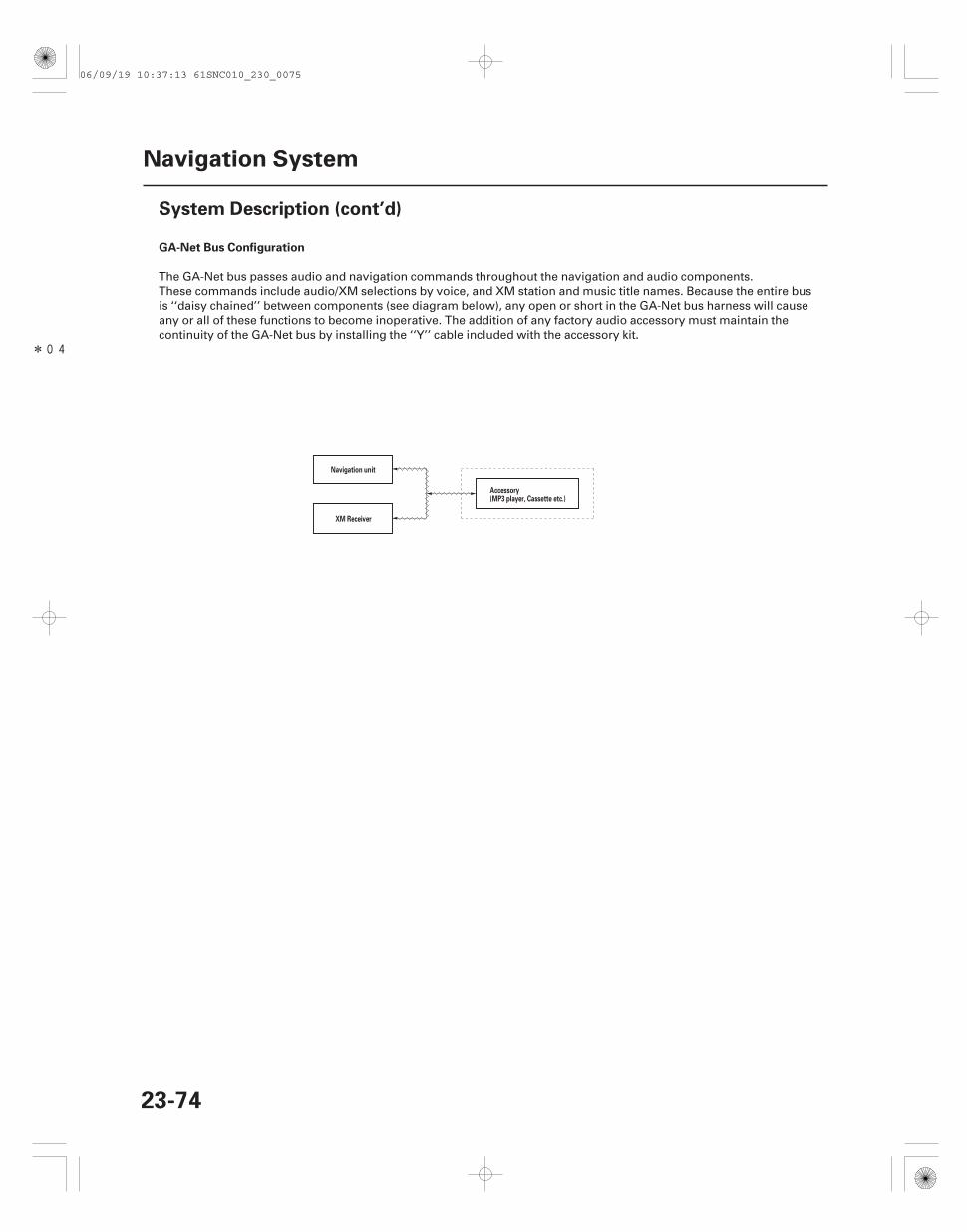
*04
GA-Net Bus Configuration
23-74
Navigation System
System Description (cont’d)
Navigation unit
XM Receiver
Accessory(MP3 player, Cassette etc.)
The GA-Net bus passes audio and navigation commands throughout the navigation and audio components.These commands include audio/XM selections by voice, and XM station and music title names. Because the entire busis ‘‘daisy chained’’ between components (see diagram below), any open or short in the GA-Net bus harness will causeany or all of these functions to become inoperative. The addition of any factory audio accessory must maintain thecontinuity of the GA-Net bus by installing the ‘‘Y’’ cable included with the accessory kit.
06/09/19 10:37:13 61SNC010_230_0075
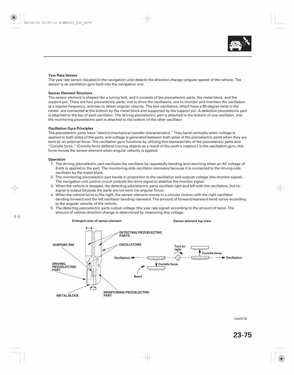
05
Yaw Rate Sensor
Sensor Element Structure
Oscillation Gyro Principles
Operation
23-75
Enlarged view of sensor element
DETECTING PIEZOELECTRICPARTS
OSCILLATORSSUPPORT PIN
DRIVINGPIEZOELECTRICPART
METAL BLOCKMONITORING PIEZOELECTRICPART
Bend
Oscillation
Coriolis force
Turn toright
Coriolis force
Oscillation
Sensor element top view
The yaw rate sensor (located in the navigation unit) detects the direction change (angular speed) of the vehicle. Thesensor is an oscillation gyro built into the navigation unit.
The sensor element is shaped like a tuning fork, and it consists of the piezoelectric parts, the metal block, and thesupport pin. There are four piezoelectric parts: one to drive the oscillators, one to monitor and maintain the oscillationat a regular frequency, and two to detect angular velocity. The two oscillators, which have a 90-degree twist in thecenter, are connected at the bottom by the metal block and supported by the support pin. A detection piezoelectric partis attached to the top of each oscillator. The driving piezoelectric part is attached to the bottom of one oscillator, andthe monitoring piezoelectric part is attached to the bottom of the other oscillator.
The piezoelectric parts have ‘‘electric/mechanical transfer characteristics.’’ They bend vertically when voltage isapplied to both sides of the parts, and voltage is generated between both sides of the piezoelectric parts when they arebent by an external force. The oscillation gyro functions by utilizing this characteristic of the piezoelectric parts and‘‘Coriolis force.’’ (Coriolis force deflects moving objects as a result of the earth’s rotation.) In the oscillation gyro, thisforce moves the sensor element when angular velocity is applied.
1. The driving piezoelectric part oscillates the oscillator by repeatedly bending and returning when an AC voltage of6 kHz is applied to the part, The monitoring-side oscillator resonates because it is connected to the driving-sideoscillator by the metal block.
2. The monitoring piezoelectric part bends in proportion to the oscillation and outputs voltage (the monitor signal).The navigation unit control circuit controls the drive signal to stabilize the monitor signal.
3. When the vehicle is stopped, the detecting piezoelectric parts oscillate right and left with the oscillators, but nosignal is output because the parts are not bent (no angular force).
4. When the vehicle turns to the right, the sensor element moves in a circular motion with the right oscillatorbending forward and the left oscillator bending rearward. The amount of forward/rearward bend varies accordingto the angular velocity of the vehicle.
5. The detecting piezoelectric parts output voltage (the yaw rate signal) according to the amount of bend. Theamount of vehicle direction change is determined by measuring this voltage.
(cont’d)
06/09/19 10:37:13 61SNC010_230_0076
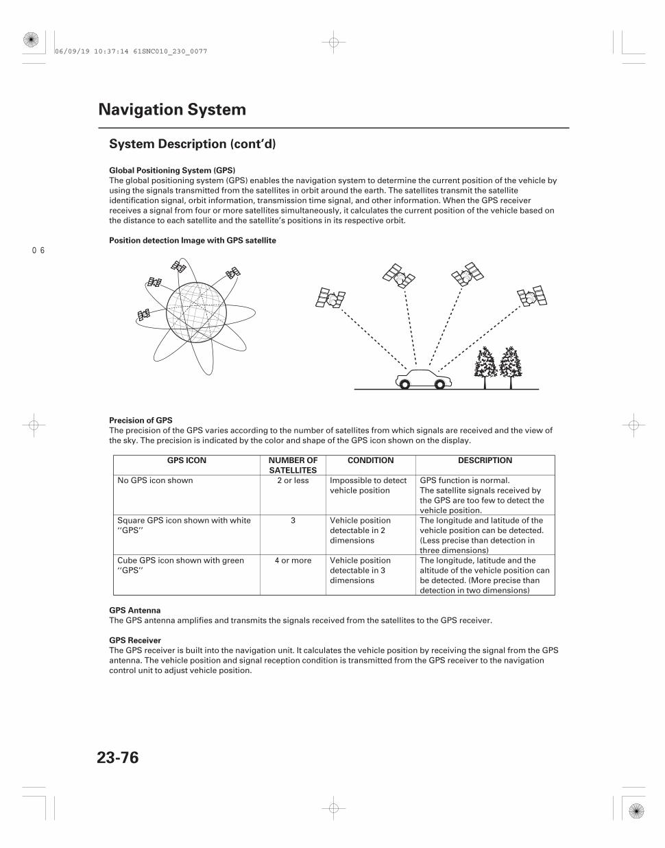
06
Global Positioning System (GPS)
Position detection Image with GPS satellite
Precision of GPS
GPS ICON NUMBER OF
SATELLITES
CONDITION DESCRIPTION
GPS Antenna
GPS Receiver
23-76
Navigation System
System Description (cont’d)
The global positioning system (GPS) enables the navigation system to determine the current position of the vehicle byusing the signals transmitted from the satellites in orbit around the earth. The satellites transmit the satelliteidentification signal, orbit information, transmission time signal, and other information. When the GPS receiverreceives a signal from four or more satellites simultaneously, it calculates the current position of the vehicle based onthe distance to each satellite and the satellite’s positions in its respective orbit.
The precision of the GPS varies according to the number of satellites from which signals are received and the view ofthe sky. The precision is indicated by the color and shape of the GPS icon shown on the display.
No GPS icon shown 2 or less Impossible to detectvehicle position
GPS function is normal.The satellite signals received bythe GPS are too few to detect thevehicle position.
Square GPS icon shown with white‘‘GPS’’
3 Vehicle positiondetectable in 2dimensions
The longitude and latitude of thevehicle position can be detected.(Less precise than detection inthree dimensions)
Cube GPS icon shown with green‘‘GPS’’
4 or more Vehicle positiondetectable in 3dimensions
The longitude, latitude and thealtitude of the vehicle position canbe detected. (More precise thandetection in two dimensions)
The GPS antenna amplifies and transmits the signals received from the satellites to the GPS receiver.
The GPS receiver is built into the navigation unit. It calculates the vehicle position by receiving the signal from the GPSantenna. The vehicle position and signal reception condition is transmitted from the GPS receiver to the navigationcontrol unit to adjust vehicle position.
06/09/19 10:37:14 61SNC010_230_0077
--
-
--
Navigation Unit
Calculation of Vehicle Position
Map Matching Tuning
GPS Tuning
Distance Tuning
Route Guidance
Audio Guidance
DVD-ROM
23-77
The navigation unit calculates the vehicle position and guides you to the destination. The unit performs map matchingcorrection, GPS correction, and distance tuning. It also controls the menu functions and the DVD-ROM drive, andinterprets voice commands. With control of all these items, the navigation unit makes the navigation picture signal,then it transmits the signal to the navigation display and audio driving instructions to the audio unit.
The navigation unit calculates the vehicle position (the driving direction and the current position) by receiving thedirectional change signals from the yaw rate sensor and the travel distance signals from the PCMs vehicle speed pulse(VSP) signal.
The map matching tuning is accomplished by indicating the vehicle position on the roads on the map. The map datatransmitted from the DVD-ROM is checked against the vehicle position data, and the vehicle position is indicated onthe nearest road. Map matching tuning does not occur when the vehicle travels on a road not shown on the map, orwhen the vehicle position is far away from a road on the map.
The GPS tuning is accomplished by indicating the vehicle position as the GPS’s vehicle position. The navigation unitcompares its calculated vehicle position data with the GPS vehicle position data. If there is large difference betweenthe two, the indicated vehicle position is adjusted to the GPS vehicle position.
The distance tuning reduces the difference between the travel distance signal from the VSP and the distance data onthe map. The navigation unit compares its calculated vehicle position data with the GPS vehicle position data. Thenavigation unit then decreases the tuning value when the vehicle position is always ahead of the GPS vehicle position,and it increases the tuning value when the vehicle position is always behind the GPS vehicle position.
The navigation unit can calculate different routes to a selected destination. You have five options:• Direct Route Calculate a route that is the most direct.• Easy Route Calculate a route that minimizes the number of turns needed.• Minimize Freeways Calculate a route that avoids freeway travel. If that is not possible, keep the amount of
freeway travel to a minimum.• Mimimize Toll Roads Calculate a route that avoids, or minimizes travel on toll roads.• Maximize Freeways Calculate a route that uses freeways as much as possible.
The navigation unit transmits audio driving instructions before entering an intersection or passing a junction.The audio instructions come through the audio unit to the front speakers.
NOTE: The front speakers are muted whenever the navigation system is giving guidance commands, and all of thespeakers are muted when the voice control system is being used.
The map data (including all scale rates) is stored in the DVD-ROM. The map data includes:• Road distances, road widths, speed limits, traffic regulations, passing time at junction, distances to junctions, and
the driving instructions for audio guidance.• Latitude and longitude GPS.
(cont’d)
06/09/19 10:37:14 61SNC010_230_0078
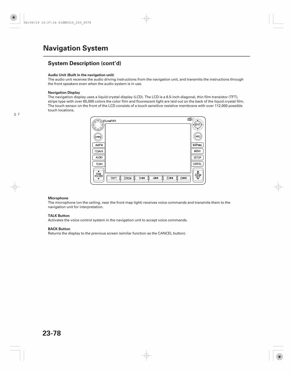
07
Audio Unit (Built in the navigation unit)
Navigation Display
Microphone
TALK Button
BACK Button
23-78
Navigation System
System Description (cont’d)
The audio unit receives the audio driving instructions from the navigation unit, and transmits the instructions throughthe front speakers even when the audio system is in use.
The navigation display uses a liquid crystal display (LCD). The LCD is a 6.5-inch-diagonal, thin film transistor (TFT),stripe type with over 65,000 colors the color film and fluorescent light are laid out on the back of the liquid crystal film.The touch sensor on the front of the LCD consists of a touch sensitive resistive membrane with over 112,000 possibletouch locations.
The microphone (on the ceiling, near the front map light) receives voice commands and transmits them to thenavigation unit for interpretation.
Activates the voice control system in the navigation unit to accept voice commands.
Returns the display to the previous screen (similar function as the CANCEL button).
06/09/19 10:37:14 61SNC010_230_0079
Glossary
Item Definition
23-79
The following is a glossary of terms pertaining to the voice recognition navigation system.
Breadcrumbs Off road tracking dots that can be followed on the map to retrace your route back to amapped (digitized) road. This function can be turned on/off in Setup screen 1.
CPU Central Processing Unit. The main device within the navigation unit that coordinatesthe rest of the electronic functions.
Database This consists of the Map data, and the POI (Points Of Interest) data stored on the DVD.DBW Drive By Wire. Allows electrical control of the throttle without the need of a
mechanical linkage.DCA Detailed coverage area, an area that is covered in the database digital mapping. For
example, the 48 continuous United States are within the DCA. Hawaii and Alaska areoutside of the DCA.
DTC Diagnostic Trouble Codes. Use the HDS tablet to obtain and troubleshoot the cause ofthese codes.
Dead Reckoning The use of the speed signal and yaw rate sensor to position the vehicle on the mapeven when tall buildings, or driving in a tunnel obscures the GPS signal.
Digitized Road A road that appears on the navigation screen. The road name will appear at thebottom of the navigation screen. If the user drives ‘‘off road,’’ the navigation systemwill display ‘‘Not on a digitized road.’’ The ‘‘breadcrumbs’’ will appear after driving for1/2 mile.
Disclaimer Screen Screen containing cautionary information. It is meant to be read carefully andacknowledged by the customer when using the navigation system.
DVD or DVD-ROM Digital Versatile Disk. The navigation program and database resides on this disk. Seethe Navigation System manual for information on how to order a replacement or anupdate DVD.
ECM Engine Control Module. Typically referred to as the ECM.FAQ Frequently Asked Question. See the Navigation System manual for a list of the
customer FAQs, and troubleshooting information.GA-Net bus This communication bus is used to pass audio, navi and accessory information
between the components and accessories.GPS Global Positioning System. A network of 24 satellites in orbit around the earth. The
navigation system can simultaneously receive signals from up to 12 satellites toaccurately position the vehicle on the map.
HDS Honda Diagnostic System. A hand-held tablet PC used for diagnosing vehicleproblems.
H/U Head Unit. The navigation system display unit assembly in the dash.Initialization This refers to the period needed to re-acquire the GPS satellite orbital information
whenever the navigation system power has been disconnected. This can take from 10to 45 minutes.
LCD Liquid Crystal Display (the navigation screen)Map Matching The received GPS information allows the navigation system to position the vehicle on
the map. Map matching has occurred if the map screen is displaying the current streetname in the bottom-shaded area.
Mic Abbreviation for the microphone used for receiving voice commands. It is locatednear the map light in the ceiling.
MW Maneuver Window. While on-route to a destination, this window displays informationabout the next maneuver.
Navi Abbreviation for the navigation system
(cont’d)
06/09/19 10:37:15 61SNC010_230_0080
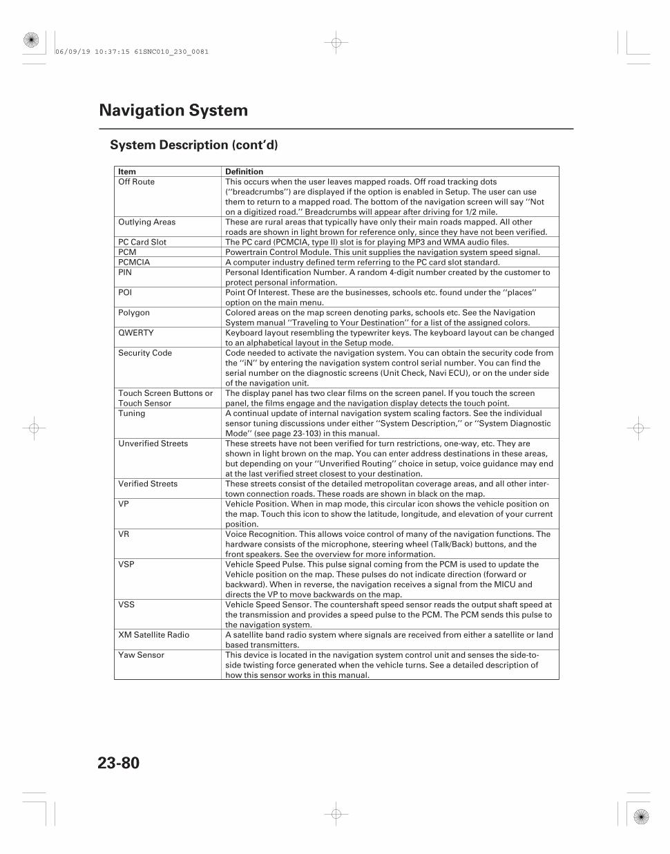
Item Definition
23-80
Navigation System
System Description (cont’d)
Off Route This occurs when the user leaves mapped roads. Off road tracking dots(‘‘breadcrumbs’’) are displayed if the option is enabled in Setup. The user can usethem to return to a mapped road. The bottom of the navigation screen will say ‘‘Noton a digitized road.’’ Breadcrumbs will appear after driving for 1/2 mile.
Outlying Areas These are rural areas that typically have only their main roads mapped. All otherroads are shown in light brown for reference only, since they have not been verified.
PC Card Slot The PC card (PCMCIA, type II) slot is for playing MP3 and WMA audio files.PCM Powertrain Control Module. This unit supplies the navigation system speed signal.PCMCIA A computer industry defined term referring to the PC card slot standard.PIN Personal Identification Number. A random 4-digit number created by the customer to
protect personal information.POI Point Of Interest. These are the businesses, schools etc. found under the ‘‘places’’
option on the main menu.Polygon Colored areas on the map screen denoting parks, schools etc. See the Navigation
System manual ‘‘Traveling to Your Destination’’ for a list of the assigned colors.QWERTY Keyboard layout resembling the typewriter keys. The keyboard layout can be changed
to an alphabetical layout in the Setup mode.Security Code Code needed to activate the navigation system. You can obtain the security code from
the ‘‘iN’’ by entering the navigation system control serial number. You can find theserial number on the diagnostic screens (Unit Check, Navi ECU), or on the under sideof the navigation unit.
Touch Screen Buttons orTouch Sensor
The display panel has two clear films on the screen panel. If you touch the screenpanel, the films engage and the navigation display detects the touch point.
Tuning A continual update of internal navigation system scaling factors. See the individualsensor tuning discussions under either ‘‘System Description,’’ or ‘‘System DiagnosticMode’’ (see page 23-103) in this manual.
Unverified Streets These streets have not been verified for turn restrictions, one-way, etc. They areshown in light brown on the map. You can enter address destinations in these areas,but depending on your ‘‘Unverified Routing’’ choice in setup, voice guidance may endat the last verified street closest to your destination.
Verified Streets These streets consist of the detailed metropolitan coverage areas, and all other inter-town connection roads. These roads are shown in black on the map.
VP Vehicle Position. When in map mode, this circular icon shows the vehicle position onthe map. Touch this icon to show the latitude, longitude, and elevation of your currentposition.
VR Voice Recognition. This allows voice control of many of the navigation functions. Thehardware consists of the microphone, steering wheel (Talk/Back) buttons, and thefront speakers. See the overview for more information.
VSP Vehicle Speed Pulse. This pulse signal coming from the PCM is used to update theVehicle position on the map. These pulses do not indicate direction (forward orbackward). When in reverse, the navigation receives a signal from the MICU anddirects the VP to move backwards on the map.
VSS Vehicle Speed Sensor. The countershaft speed sensor reads the output shaft speed atthe transmission and provides a speed pulse to the PCM. The PCM sends this pulse tothe navigation system.
XM Satellite Radio A satellite band radio system where signals are received from either a satellite or landbased transmitters.
Yaw Sensor This device is located in the navigation system control unit and senses the side-to-side twisting force generated when the vehicle turns. See a detailed description ofhow this sensor works in this manual.
06/09/19 10:37:15 61SNC010_230_0081
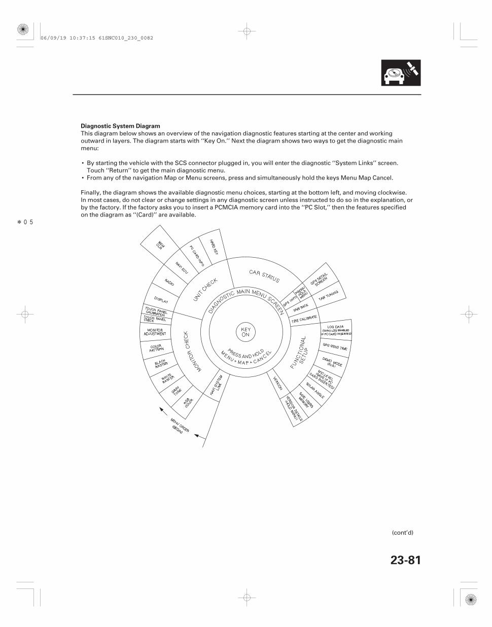
*05
Diagnostic System Diagram
23-81
This diagram below shows an overview of the navigation diagnostic features starting at the center and workingoutward in layers. The diagram starts with ‘‘Key On.’’ Next the diagram shows two ways to get the diagnostic mainmenu:
• By starting the vehicle with the SCS connector plugged in, you will enter the diagnostic ‘‘System Links’’ screen.Touch ‘‘Return’’ to get the main diagnostic menu.
• From any of the navigation Map or Menu screens, press and simultaneously hold the keys Menu Map Cancel.
Finally, the diagram shows the available diagnostic menu choices, starting at the bottom left, and moving clockwise.In most cases, do not clear or change settings in any diagnostic screen unless instructed to do so in the explanation, orby the factory. If the factory asks you to insert a PCMCIA memory card into the ‘‘PC Slot,’’ then the features specifiedon the diagram as ‘‘(Card)’’ are available.
(cont’d)
06/09/19 10:37:15 61SNC010_230_0082
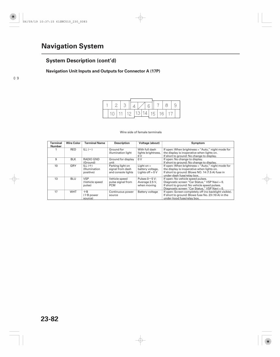
-
+
-
++
09
Navigation Unit Inputs and Outputs for Connector A (17P)
TerminalNumber
Wire Color Terminal Name Description Voltage (about) Symptom
23-82
Navigation System
System Description (cont’d)
1 RED ILL ( ) Ground forillumination light
With full dashlights brightness,0 V
If open: When brightness = ‘‘Auto,’’ night mode forthe display is inoperative when lights on.If short to ground: No change to display.
9 BLK RADIO GND(Ground)
Ground for displayunit
0 V If open: No change to display.If short to ground: No change to display.
10 GRY ILL ( )(Illuminationpositive)
Parking light onsignal from dashand console lights
Light on =battery voltage,Lights off = 0 V
If open: When brightness = ‘‘Auto,’’ night mode forthe display is inoperative when lights on.If short to ground: Blows NO. 14 (7.5 A) fuse inunder-dash fuse/relay box.
13 BLU VSP(Vehicle speedpulse)
Vehicle speedpulse signal fromPCM
Pulses 0 5 V:Average 2.5 V,when moving
If open: No vehicle speed pulses.Diagnostic screen ‘‘Car Status,’’ VSP Navi = 0.If short to ground: No vehicle speed pulses.Diagnostic screen ‘‘Car Status,’’ VSP Navi = 0.
17 WHT B( B powersource)
Continuous powersource
Battery voltage If open: Screen completely off (no backlight visible).If short to ground: Blows fuse No. 23 (10 A) in theunder-hood fuse/relay box.
Wire side of female terminals
06/09/19 10:37:15 61SNC010_230_0083
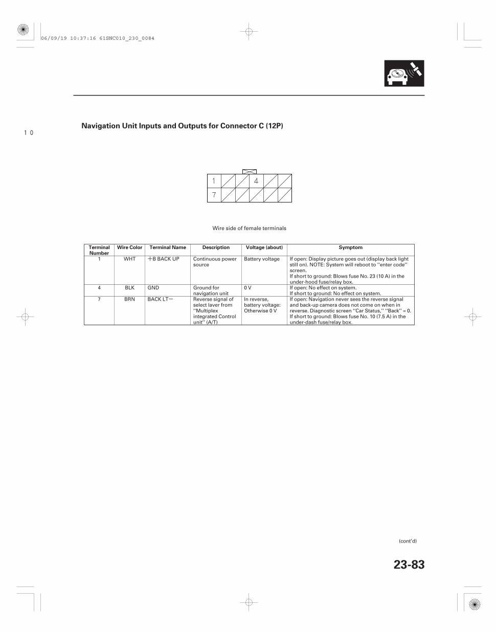
+
-
10Navigation Unit Inputs and Outputs for Connector C (12P)
TerminalNumber
Wire Color Terminal Name Description Voltage (about) Symptom
23-83
1 WHT B BACK UP Continuous powersource
Battery voltage If open: Display picture goes out (display back lightstill on). NOTE: System will reboot to ‘‘enter code’’screen.If short to ground: Blows fuse No. 23 (10 A) in theunder-hood fuse/relay box.
4 BLK GND Ground fornavigation unit
0 V If open: No effect on system.If short to ground: No effect on system.
7 BRN BACK LT Reverse signal ofselect laver from‘‘Multiplexintegrated Controlunit’’ (A/T)
In reverse,battery voltage:Otherwise 0 V
If open: Navigation never sees the reverse signaland back-up camera does not come on when inreverse. Diagnostic screen ‘‘Car Status,’’ ‘‘Back’’ = 0.If short to ground: Blows fuse No. 10 (7.5 A) in theunder-dash fuse/relay box.
(cont’d)
Wire side of female terminals
06/09/19 10:37:16 61SNC010_230_0084
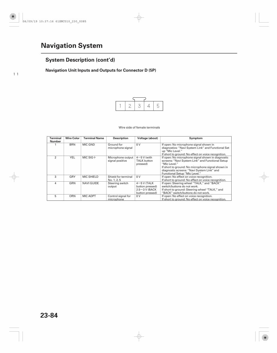
+ -
-
-
11Navigation Unit Inputs and Outputs for Connector D (5P)
TerminalNumber
Wire Color Terminal Name Description Voltage (about) Symptom
23-84
Navigation System
System Description (cont’d)
1 BRN MIC GND Ground formicrophone signal
0 V If open: No microphone signal shown indiagnostics: ‘‘Navi System Link’’ and Functional Setup ‘‘Mic Level.’’If short to ground: No effect on voice recognition.
2 YEL MIC SIG Microphone outputsignal positive
4 5 V (withTALK buttonpressed)
If open: No microphone signal shown in diagnosticscreens: ‘‘Navi System Link’’ and Functional Setup‘‘Mic Level.’’If short to ground: No microphone signal shown indiagnostic screens: ‘‘Navi System Link’’ andFunctional Setup ‘‘Mic Level.’’
3 GRY MIC SHIELD Shield for terminalNo. 1, 2, 5
0 V If open: No effect on voice recognition.If short to ground: No effect on voice recognition.
4 GRN NAVI GUIDE Steering switchoutput
4 5 V (TALKbutton pressed)2.5 3 V (BACKbutton pressed)
If open: Steering wheel ‘‘TALK,’’ and ‘‘BACK’’switch/buttons do not work.If short to ground: Steering wheel ‘‘TALK,’’ and‘‘BACK’’ switch/buttons do not work.
5 ORN MIC ADPT Control signal formicrophone
0 V If open: No effect on voice recognition.If short to ground: No effect on voice recognition.
Wire side of female terminals
06/09/19 10:37:16 61SNC010_230_0085
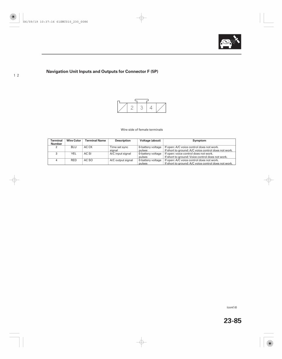
12Navigation Unit Inputs and Outputs for Connector F (5P)
TerminalNumber
Wire Color Terminal Name Description Voltage (about) Symptom
23-85
2 BLU AC CK Time set syncsignal
0-battery voltagepulses
If open: A/C voice control does not work.If short to ground: A/C voice control does not work.
3 YEL AC SI A/C input signal 0-battery voltagepulses
If open: voice control does not work.If short to ground: Voice control does not work.
4 RED AC SO A/C output signal 0-battery voltagepulses
If open: A/C voice control does not work.If short to ground: A/C voice control does not work.
(cont’d)
Wire side of female terminals
06/09/19 10:37:16 61SNC010_230_0086
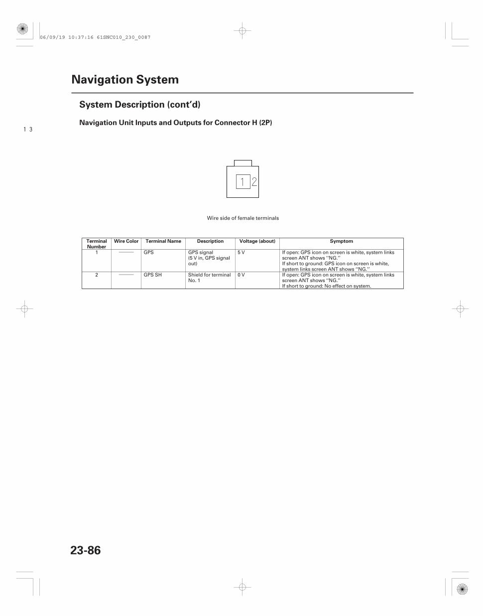
―――
―――
13Navigation Unit Inputs and Outputs for Connector H (2P)
TerminalNumber
Wire Color Terminal Name Description Voltage (about) Symptom
23-86
Navigation System
System Description (cont’d)
1 GPS GPS signal(5 V in, GPS signalout)
5 V If open: GPS icon on screen is white, system linksscreen ANT shows ‘‘NG.’’If short to ground: GPS icon on screen is white,system links screen ANT shows ‘‘NG.’’
2 GPS SH Shield for terminalNo. 1
0 V If open: GPS icon on screen is white, system linksscreen ANT shows ‘‘NG.’’If short to ground: No effect on system.
Wire side of female terminals
06/09/19 10:37:16 61SNC010_230_0087
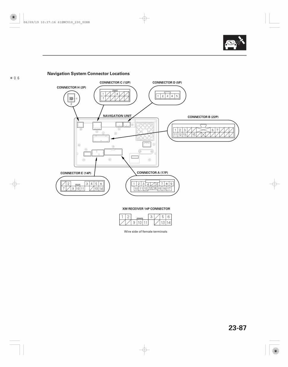
*06Navigation System Connector Locations
23-87
XM RECEIVER 14P CONNECTOR
NAVIGATION UNIT
CONNECTOR E (14P) CONNECTOR A (17P)
CONNECTOR B (22P)
CONNECTOR D (5P)CONNECTOR C (12P)
CONNECTOR H (2P)
Wire side of female terminals
06/09/19 10:37:16 61SNC010_230_0088
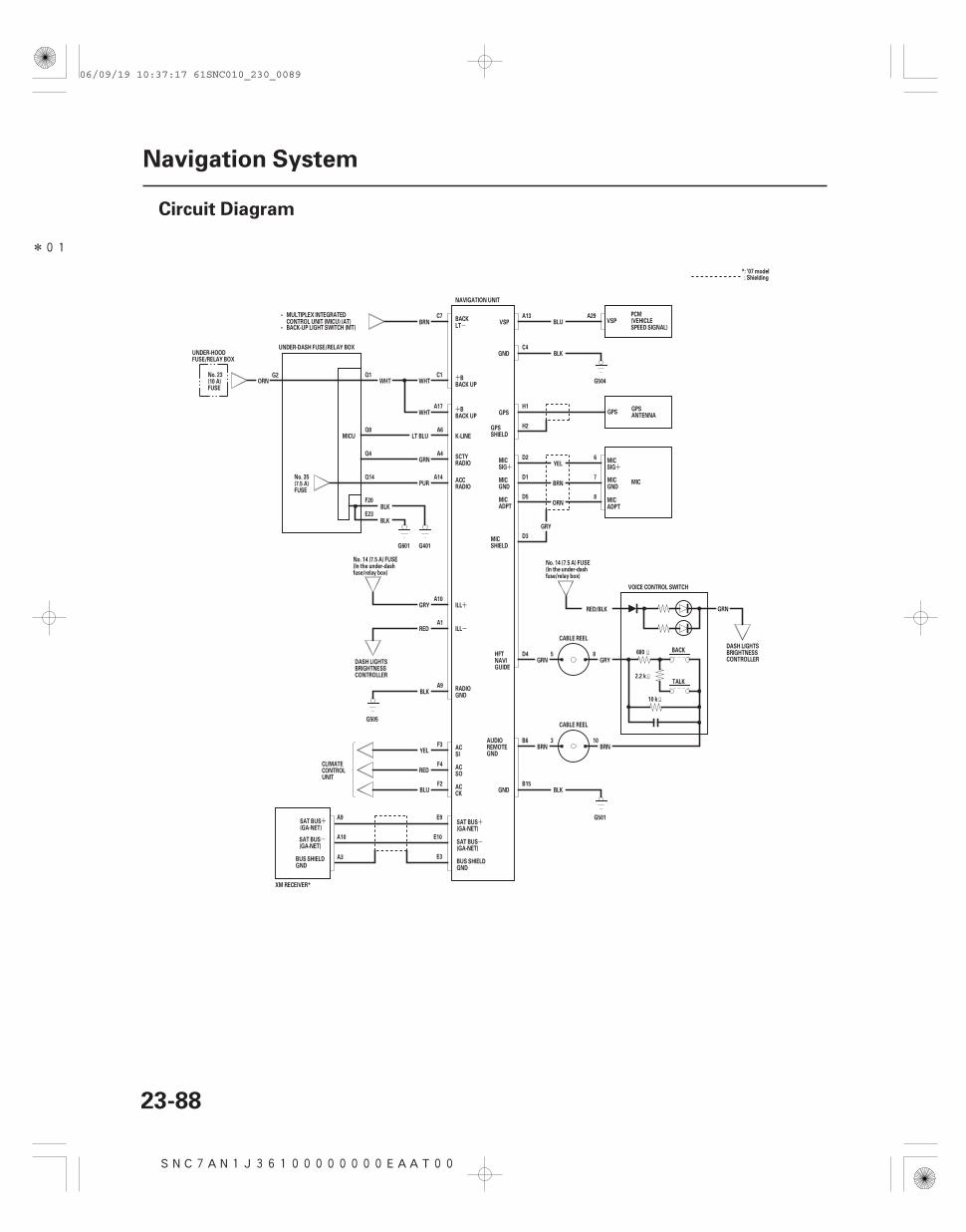
*01
SNC7AN1J36100000000EAAT00
+
-
+
+
-
+
+
+
- -
+
23-88
Navigation System
Circuit Diagram
BACK-UP LIGHT SWITCH (MT)•
•
K-LINE
BLK
G401
MICU
A14PUR
Q14
Q4GRN
A4
A6LT BLU
Q8
Q1WHT
WHT
UNDER-DASH FUSE/RELAY BOX
ORN
G505
BLKB15
GND
G501
BRN10
BRN3
CABLE REEL
B6
D5ORN
8
A29
7
6
D4
CABLE REEL
GRNRED/BLK
BACK
TALK
5GRY
GRY
D3
BRND1
D2YEL
GPSH1
H2
G504
GNDC4
BLK
VSP BLUA13
ILL
ILL
BLUF2
F4RED
YELF3
A1
A9
A10GRY
BLK
RED
A17
C1
C7BRN
WHT
NAVIGATION UNIT
VOICE CONTROL SWITCH
8GRN
680
10 k
2.2 k
CLIMATECONTROLUNIT
GPSSHIELD
MICSHIELD
MICGND
MICSIG
HFTNAVIGUIDE
UNDER-HOODFUSE/RELAY BOX
MICADPT
ACSI
ACSO
ACCK
RADIOGND
DASH LIGHTSBRIGHTNESSCONTROLLER
No. 14 (7.5 A) FUSE(In the under-dashfuse/relay box)
No. 14 (7.5 A) FUSE(In the under-dashfuse/relay box)
DASH LIGHTSBRIGHTNESSCONTROLLER
BBACK UP
BACKLT
No. 35(7.5 A)FUSE
No. 23(10 A)FUSE
BBACK UP
SCTYRADIO
ACCRADIO
AUDIOREMOTEGND
MULTIPLEX INTEGRATEDCONTROL UNIT (MICU) (AT)
MIC
PCM(VEHICLESPEED SIGNAL)
GPSANTENNA
VSP
GPS
MICSIG
MICGND
MICADPT
A10
A9
E3
E10
E9SAT BUS(GA-NET)
SAT BUS(GA-NET)
SAT BUS(GA-NET)
SAT BUS(GA-NET)
BUS SHIELDGND
XM RECEIVER*
A3BUS SHIELDGND
: Shielding*: ’07 model
BLK
G601
F20
E23
G2
06/09/19 10:37:17 61SNC010_230_0089
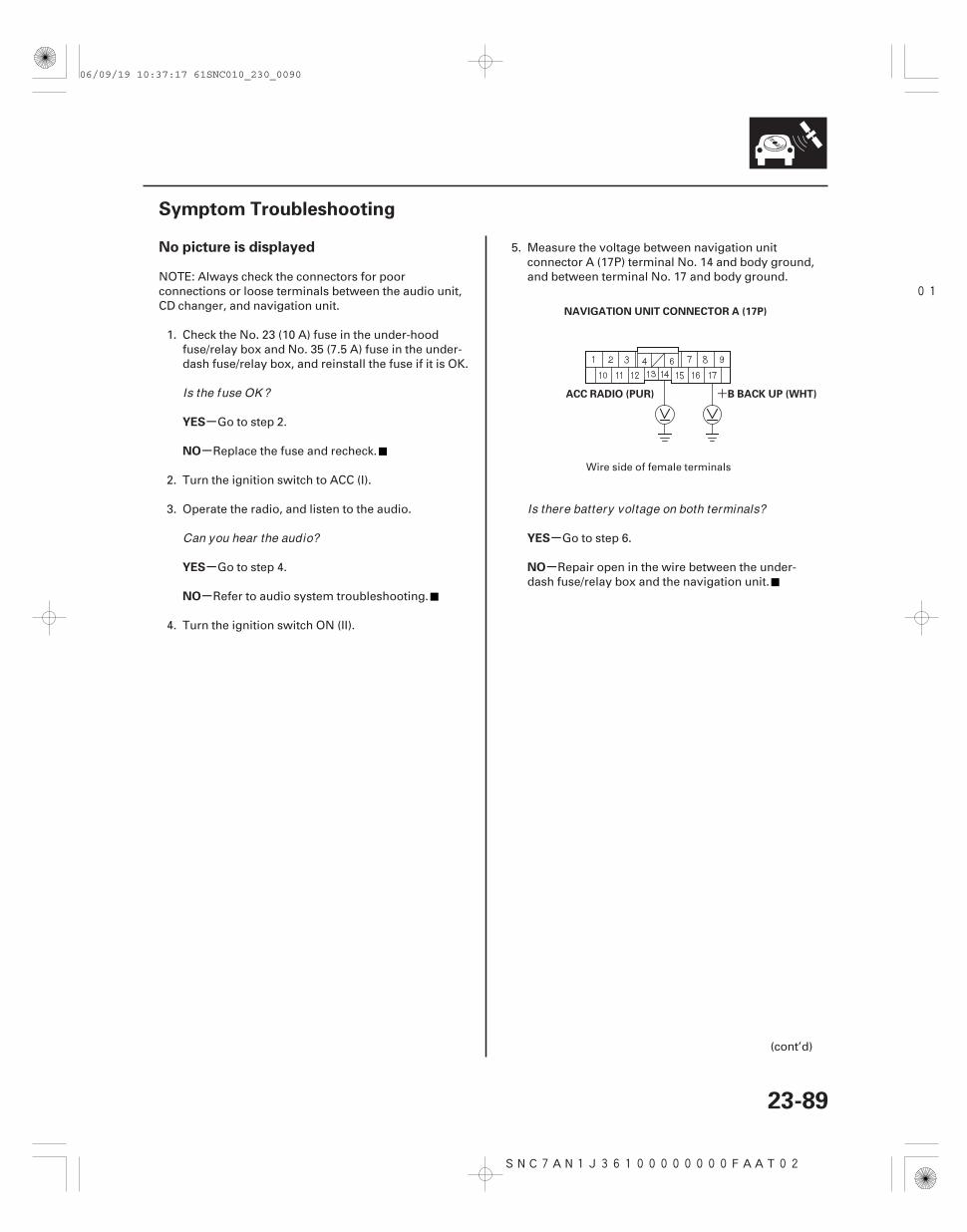
01
SNC7AN1J36100000000FAAT02
+
-
-
-
-
-
-
No picture is displayed
YES
NO
YES
NO
YES
NO
23-89
Symptom Troubleshooting
NAVIGATION UNIT CONNECTOR A (17P)
B BACK UP (WHT)ACC RADIO (PUR)
NOTE: Always check the connectors for poorconnections or loose terminals between the audio unit,CD changer, and navigation unit.
1. Check the No. 23 (10 A) fuse in the under-hoodfuse/relay box and No. 35 (7.5 A) fuse in the under-dash fuse/relay box, and reinstall the fuse if it is OK.
Go to step 2.
Replace the fuse and recheck.
2. Turn the ignition switch to ACC (I).
3. Operate the radio, and listen to the audio.
Go to step 4.
Refer to audio system troubleshooting.
4. Turn the ignition switch ON (II).
5. Measure the voltage between navigation unitconnector A (17P) terminal No. 14 and body ground,and between terminal No. 17 and body ground.
Go to step 6.
Repair open in the wire between the under-dash fuse/relay box and the navigation unit.
(cont’d)
Wire side of female terminals
Is the fuse OK ?
Can you hear the audio?
Is there battery voltage on both terminals?
06/09/19 10:37:17 61SNC010_230_0090
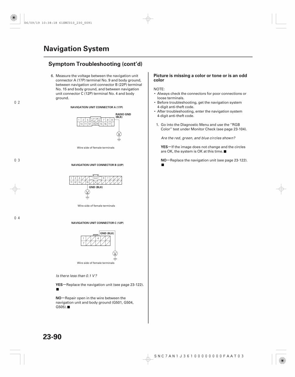
02
03
04
SNC7AN1J36100000000FAAT03
-
-
-
-
YES
NO
YES
NO
Picture is missing a color or tone or is an oddcolor
23-9023-90
Navigation System
Symptom Troubleshooting (cont’d)
NAVIGATION UNIT CONNECTOR A (17P)
RADIO GND(BLK)
NAVIGATION UNIT CONNECTOR B (22P)
GND (BLK)
NAVIGATION UNIT CONNECTOR C (12P)
GND (BLK)
6. Measure the voltage between the navigation unitconnector A (17P) terminal No. 9 and body ground,between navigation unit connector B (22P) terminalNo. 15 and body ground, and between navigationunit connector C (12P) terminal No. 4 and bodyground.
Replace the navigation unit (see page 23-122).
Repair open in the wire between thenavigation unit and body ground (G501, G504,G505).
NOTE:• Always check the connectors for poor connections or
loose terminals.• Before troubleshooting, get the navigation system
4-digit anti-theft code.• After troubleshooting, enter the navigation system
4-digit anti-theft code.
1. Go into the Diagnostic Menu and use the ‘‘RGBColor’’ test under Monitor Check (see page 23-104).
If the image does not change and the circlesare OK, the system is OK at this time.
Replace the navigation unit (see page 23-122).
Wire side of female terminals
Wire side of female terminals
Wire side of female terminals
Is there less than 0.1 V?
Are the red, green, and blue circles shown?
06/09/19 10:38:18 61SNC010_230_0091
SNC7AN1J36100000000FAAT04
-
-
-
-
-
-
Picture has lines/rolls/other issues or is anodd color
YES
NO
YES
NO
YES
NO
23-91
NOTE:• Always check the connectors for poor connections or
loose terminals.• Before troubleshooting, get the navigation system
anti-theft code.• After troubleshooting, enter the navigation system
anti-theft code.
1. Check for electronic aftermarket accessories(possibly hidden) mounted near the navigation unit.
Disable the accessories, and recheck.
Go to step 2.
2. Go into the Diagnostic mode and use the ‘‘RGBColor’’ test under Monitor Check (see page 23-104).
Do the troubleshooting for the picture ismissing a color or tone or is an odd color (see page23-90).
Go to step 3.
3. Turn the ignition switch to the ACC (I) position, andobserve the navigation picture.
Check for sources of electrical noise, such aspoor battery connection, alternator, defectivebattery, aftermarket accessories or cell phone, andpoor pin fits at the display or control unit.
Replace the navigation unit (see page 23-122).
Are there any electronic accessor ies?
Is the picture missing a red, green or blue colorcircle?
Did the image improve?
06/09/19 10:38:18 61SNC010_230_0092
SNC7AN1J36100000000FAAT05 SNC7AN1J36100000000FAAT06
-
-
-
-
-
-
Navigation display buttons do not work orrespond properly
GPS icon is white or not shown
YES
NO
YES
NO
YES
NO
23-9223-92
Navigation System
Symptom Troubleshooting (cont’d)
NOTE:• Always check connectors for poor contact and poor
pin fits.• Before troubleshooting, get the navigation anti-theft
code.• Before troubleshooting, write down all the audio
presets, and re-enter them after repairs are complete.• Always verify the concern and compare the system
operation to a known-good vehicle with the samesoftware loaded whenever possible. If the concern isduplicated in the known-good vehicle, then it can beconsidered a characteristic of the system.
1. Turn the ignition switch ON (II).
Replace the navigation unit (see page 23-122).
Refer to troubleshooting for no picture isdisplayed (see page 23-89).
NOTE:• Make sure the vehicle is parked outside and away
from buildings.• Refer to GPS Information (see page 23-109) for
realtime satellite reception display.• Check for window tinting above the GPS antenna and
any non-OEM accessories mounted near thenavigation unit or GPS antenna.
1. Check for metallic window tint on the windshieldand electronic aftermarket accessories (possiblyhidden) mounted near the GPS antenna or thenavigation unit.
Remove tint or the accessories andrecheck.
Go to step 2.
2. Go into the Diagnostic Menu and use the ‘‘NaviSystem Link’’ test (see page 23-103) to check theGPS antenna.
Use the ‘‘Navi ECU’’ test under Unit Check(see page 23-106) to check for a kinked, crushed, ordisconnected GPS antenna wire. If necessary, try aknown-good GPS antenna. If icon is still red,replace the navigation unit.
Check that nothing is blocking the GPSantenna located behind the gauge assembly andrecheck. Substitute a known-good navigation unit,and recheck.
Does the navigation display turn on?
Is there metall ic window tint or electronicaccessor ies?
Is ‘‘GPS Ant’’ icon red?
06/09/19 10:38:18 61SNC010_230_0093
SNC7AN1J36100000000FAAT07 SNC7AN1J36100000000FAAT08
-
-
-
-
-
-
-
-
Voice guidance cannot be heard, is brokenup, or there is too much static
Voice recognition does not work
YES
NO
YES
NO
YES
NO
YES
NO
23-9323-93
NOTE:• Always check that the volume setting and voice
feedback are turned ON.• Always check the connectors for poor connection or
loose terminals.• Before troubleshooting, make sure you have the
navigation system 4-digit anti-theft code, then writedown the audio presets.
• After troubleshooting, enter the navigation systemanti-theft code, then enter the audio presets.
1. Press the display unit SET-UP button.
2. Check the volume setting for the navigation system.
Set the volume to an audible level.
Go to step 3.
3. Check the radio operation.
Go to step 4.
Troubleshoot the audio system.
4. Go into the Diagnostic Menu and use the ‘‘NaviSystem Link’’ test (see page 23-103) to check theradio.
Troubleshoot the audio system.
Go to step 5.
5. Check the voice control switch (see page 23-123).
Replace the navigation unit (see page 23-122).
Replace the voice control switch unit(see page 23-123).
NOTE:• Always check the connector for poor connection or
loose terminals.• Before troubleshooting, make sure you have the
navigation system 4-digit anti-theft code, then writedown the audio presets.
• After troubleshooting, enter the navigation systemanti-theft code, then enter the audio presets.
Before assuming that a voice complaint is hardwarerelated, ensure that the voice control system is beingoperated correctly.
• Make sure you are on the correct screen when tryingto issue a voice command. For instance, thecommand ‘‘Find the nearest Italian Restaurant’’ onlyworks on a Map screen.(See the Navigation System Manual for a completelist of allowed voice commands for the informationbeing displayed.)
• Close the windows, moonroof, and doors.• Set the fan speed to low (1 or 2).• Adjust the air flow from the air conditioning vents so
that they do not blow against the microphone on theceiling.
• Pause after pressing the TALK button, then give avoice command clearly in a natural speaking voice. Ifthe system cannot recognize your command, speaklouder.
• If the microphone picks up voices other than yours,the system may not interpret your voice commandscorrectly.
• If you speak a command with something in yourmouth, or your voice is too husky, the system maymisunderstand your command.
• Compare the system operation with a known-goodvehicle. Have more than one person test the systemoperation. If the known-good vehicle performs thesame, it is a characteristic of the system.
(cont’d)
Is it set to OFF?
Can you hear the radio?
Is ‘‘Radio’’ icon red?
Is the voice control switch OK ?
06/09/19 10:38:19 61SNC010_230_0094
SNC7AN1J36100000000FAAT09
-
-
-
-
-
-
-
-
-
-
YES
NO
YES
NO
YES
NO
YES
NO
YES
NO
Vehicle position icon constantly leaves road,moves erratically, or is very far from actualposition
23-9423-94
Navigation System
Symptom Troubleshooting (cont’d)
1. Go into the Diagnostic Menu and use the ‘‘MicLevel’’ test under Functional Setup (see page23-113) to check the operation of the TALK andBACK buttons.
Go to step 2.
Check for an open, or short to ground on thenavigation unit connector D (5P) terminal No. 4.
2. Use the ‘‘Mic Level’’ diagnostic under FunctionalSetup (see page 23-113) to check the operation ofthe microphone.
Check the operation of the voice controlsystem (see the Navigation System Manual) andcompare system operation with a known-goodvehicle.
Go to step 3.
3. Check the voice control switch (see page 23-123).
Check for a loose front map light(microphone) assembly. If OK, check for an open,or short to ground on navigation unit connector D(5P) terminals No. 1, No. 2, and No. 5. If the wiresare OK, substitute a known-good microphoneassembly.
Replace the voice control switch (see page23-123).
1. Check the GPS icon on the navigation picture.
Do the troubleshooting for GPS icon is whiteor not shown (see page 23-92).
Go to step 2.
2. Go into the Diagnostic Menu, and use the ‘‘YawRate’’ test (see page 23-111) to check the yaw ratesensor.
3. Go into the Diagnostic Menu and use the ‘‘CarStatus’’ test (see page 23-108) to check the vehiclespeed pulse.
The problem may be a normal characteristic.Check to see if the problem occurs in the sameplace. If it does, the problem could be in thedatabase. Compare to a known-good vehicle underthe same conditions. If you can duplicate theproblem, report it. Refer to the CustomerAssistance section of the Navigation Systemmanual, ‘‘Reporting Errors’’.
If the problem is the yaw rate sensor, replacethe navigation unit (see page 23-122). If theproblem is the vehicle speed pulse, troubleshootthe vehicle speed signal circuit.
Are the TALK and BACK buttons operational?
Is the microphone operational?
Is voice control switch OK ?
Is the GPS icon on the map screen?
Are the yaw rate sensor and vehicle speed pulseOK ?
06/09/19 10:38:19 61SNC010_230_0095
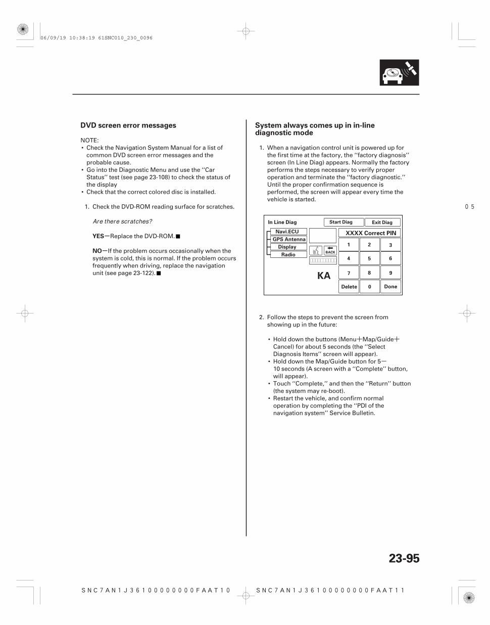
SNC7AN1J36100000000FAAT10
+ +
-
05
SNC7AN1J36100000000FAAT11
-
-
DVD screen error messages System always comes up in in-linediagnostic mode
YES
NO
23-9523-95
Start Diag Exit Diag
Navi.ECU
In Line Diag
GPS Antenna
Display
Radio
Delete Done0
1 2 3
654
7 8 9
BACK
XXXX Correct PIN
KA
NOTE:• Check the Navigation System Manual for a list of
common DVD screen error messages and theprobable cause.
• Go into the Diagnostic Menu and use the ‘‘CarStatus’’ test (see page 23-108) to check the status ofthe display
• Check that the correct colored disc is installed.
1. Check the DVD-ROM reading surface for scratches.
Replace the DVD-ROM.
If the problem occurs occasionally when thesystem is cold, this is normal. If the problem occursfrequently when driving, replace the navigationunit (see page 23-122).
1. When a navigation control unit is powered up forthe first time at the factory, the ‘‘factory diagnosis’’screen (In Line Diag) appears. Normally the factoryperforms the steps necessary to verify properoperation and terminate the ‘‘factory diagnostic.’’Until the proper confirmation sequence isperformed, the screen will appear every time thevehicle is started.
2. Follow the steps to prevent the screen fromshowing up in the future:
• Hold down the buttons (Menu Map/GuideCancel) for about 5 seconds (the ‘‘SelectDiagnosis Items’’ screen will appear).
• Hold down the Map/Guide button for 510 seconds (A screen with a ‘‘Complete’’ button,will appear).
• Touch ‘‘Complete,’’ and then the ‘‘Return’’ button(the system may re-boot).
• Restart the vehicle, and confirm normaloperation by completing the ‘‘PDI of thenavigation system’’ Service Bulletin.
Are there scratches?
06/09/19 10:38:19 61SNC010_230_0096
SNC7AN1J36100000000FAAT18
+
SNC7AN1J36100000000FAAT12
-
-
-
-
-
-
Navigation cannot control A/C by voice Display day/night mode does not work
YES
NO
YES
NO
YES
NO
23-9623-96
Navigation System
Symptom Troubleshooting (cont’d)
NOTE:• Always check the connectors for poor connections or
loose terminals.• Before troubleshooting, get the navigation system
anti-theft code.• After troubleshooting, enter the navigation system
anti-theft code.• Verify that the correct navigation unit is installed for
this model. Go into the Diagnostic Menu and use‘‘Version’’ (see page 23-119).
1. Go into the Diagnostic Menu and use the ‘‘NaviSystem Link’’ test (see page 23-103).
Do the climate control systemtroubleshooting.
Check for an open or short to ground betweennavigation unit connector F (5P) terminals No. 2,No. 3, and No. 4 and climate control unit connectorA (32P) terminals No. 28, No. 29, and No. 30respectively. If OK, check the climate controlsystem for normal operation. If the climate controlsystem works properly, substitute a known-goodnavigation unit and recheck.
NOTE:• Always check the connectors for poor connection or
loose terminal.• Before troubleshooting, get the navigation system
anti-theft code.• After troubleshooting, enter the navigation system
anti-theft code.• Full brightness on the instrument panel brightness
control causes the system to stay in the day mode,even when the lights are on.
1. Make sure the instrument panel brightness controlis not on full brightness. Turn the headlights on,and adjust the dash lights brightness to the middlerange.
2. Change the day/night mode under Set-up to ‘‘Auto’’and recheck.
The system is OK at this time.
Go to step 3.
3. Go into the Diagnostic Menu and use the ‘‘CarStatus’’ test to check for an ILL signal (see page23-108).
Replace the navigation unit (see page 23-122).
Check the ILL circuit between thenavigation unit and No. 14 (7.5 A) fuse in the under-dash fuse/relay box.
Is the ‘‘Air-con’’ icon red?
Does the display change to day and night modeswhen turning the headlights on and of f?
Is ‘‘ILL’’ signal OK ?
06/09/19 10:38:19 61SNC010_230_0097
SNC7AN1J36100000000FAAT13 SNC7AN1J36100000000FAAT14
-
-
-
-
System locks up or freezes constantly Vehicle icon wanders across the map whendriving (does not follow a displayed road) ormap or vehicle ICON spins
YES
NO
YES
NO
23-9723-97
NOTE: Check that the correct colored DVD is installed.
1. Start the engine and turn the ignition switch OFF,then turn the ignition switch ON (II).
The system is OK at this time.
Check the DVD for scratches or damage, andthe navigation unit for water damage. If OK, go intothe Diagnostic Menu and do all of the ‘‘Unit Check’’tests (see page 23-106). Also check for low batterycharge or poor charging system performance.
NOTE: This symptom is caused by a defective yaw ratesensor. Do this diagnostic when the vehicle is cold andthen again when it is warm.
1. Go into the Diagnostic Menu and use the ‘‘YawRate’’ test (see page 23-111).
The system is OK.
Replace the navigation unit (see page 23-122).
Does the system reboot?
Are the values correct?
06/09/19 10:38:19 61SNC010_230_0098
SNC7AN1J36100000000FAAT15 SNC7AN1J36100000000FAAT16
-
-
-
-
-
-
-
-
Vehicle icon moves by itself when parked Navigation stays on with ignition switch off
YES
NO
YES
NO
YES
NO
YES
NO
23-9823-98
Navigation System
Symptom Troubleshooting (cont’d)
NOTE:• Always check the connectors for poor connection or
loose terminals.• Before troubleshooting, get the navigation system
anti-theft code, then write down the audio presets.• After troubleshooting, re-enter the anti-theft code,
and re-initialize the navigation system, then enter theaudio presets.
1. Start the engine.
2. From the main menu, select places, then select anydestination, and begin the trip.
3. With the vehicle parked, watch the vehicle icon onthe display.
Replace the navigation unit (see page 23-122).
The system is OK at this time.
NOTE:• Always check the connectors for poor connection or
loose terminals.• Before troubleshooting, get the navigation system
anti-theft code, then write down the audio presets.• After troubleshooting, re-enter the anti-theft code,
and re-initialize the navigation system, then enter theaudio presets.
• Check for aftermarket accessories that use the samepower circuit. A feedback can cause this problem.
1. Remove the key from the ignition.
Go to step 2.
The system is OK at this time.
2. The vehicle may have been used as ademonstration vehicle at an event like an autoshow. In these events, power is often jumpered tothe navigation system so that the ignition key is notneeded in the vehicle. At the end of the show, thejumper wire may not have been removed. Checkthe navigation unit connector A (17P) for a ‘‘non-factory’’ jumper wire in series with the factorycable.
Remove the jumper wire, and re-test. Returnthe jumper wire to Tech Line.
Go to step 3.
3. Check if the audio unit works.
Troubleshoot the ACC circuit for a short topower with another circuit.
Replace the navigation unit (see page 23-122).
Does the vehicle position icon move by itself ?
Does the navigation screen stay on?
Is there a jumper wire?
Does the audio unit work with the ignition switchof f?
06/09/19 10:38:20 61SNC010_230_0099
SNC7AN1J36100000000FAAT17
-
-
-
-
Navigation cannot control audio/disc
YES
NO
YES
NO
23-99
1. Make sure the anti-theft code for the navigationsystem is entered.
2. Go into the Diagnostic Menu and use the ‘‘NaviSystem Link’’ test (see page 23-103).
Do the troubleshooting for the voiceguidance cannot be heard (see page 23-93).
Go to step 3.
3. Substitute a known-good navigation unit (see page23-122), and recheck.
Replace the navigation unit (see page 23-122).
Do the audio system troubleshooting.
Is the ‘‘Radio’’ icon red?
Can the navigation control audio?
06/09/19 10:38:20 61SNC010_230_0100
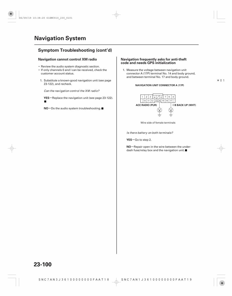
SNC7AN3J36100000000FAAT18
*01
SNC7AN1J36100000000FAAT19
+
-
-
-
-
Navigation cannot control XM radio Navigation frequently asks for anti-theftcode and needs GPS initialization
YES
NO
YES
NO
23-10023-100
Navigation System
Symptom Troubleshooting (cont’d)
NAVIGATION UNIT CONNECTOR A (17P)
B BACK UP (WHT)ACC RADIO (PUR)
• Review the audio system diagnostic section.• If only channels 0 and I can be received, check the
customer account status.
1. Substitute a known-good navigation unit (see page23-122), and recheck.
Replace the navigation unit (see page 23-122).
Do the audio system troubleshooting.
1. Measure the voltage between navigation unitconnector A (17P) terminal No. 14 and body ground,and between terminal No. 17 and body ground.
Go to step 2.
Repair open in the wire between the under-dash fuse/relay box and the navigation unit.
Wire side of female terminals
Can the navigation control the XM radio?
Is there battery on both terminals?
06/09/19 10:38:20 61SNC010_230_0101
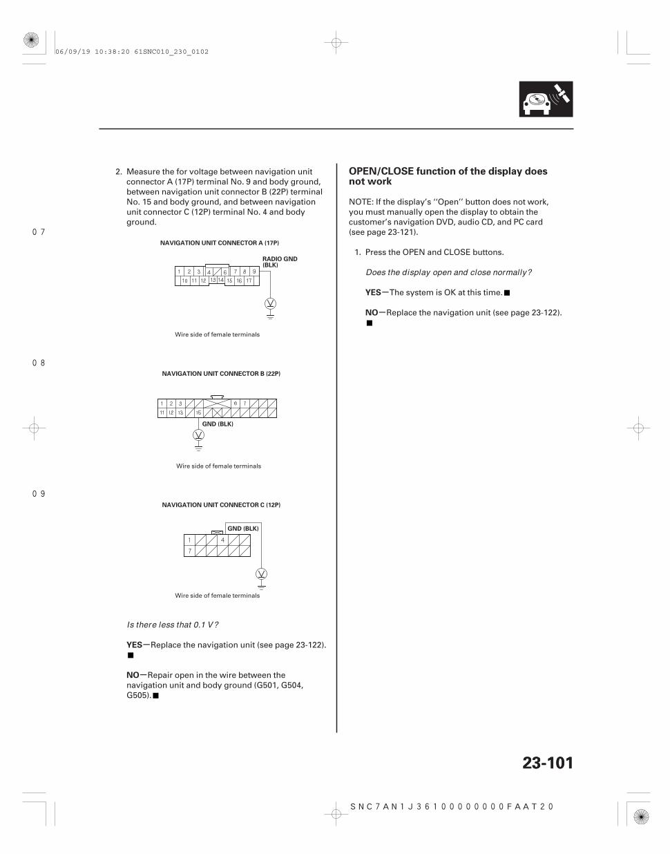
07
08
09
SNC7AN1J36100000000FAAT20
-
-
-
-
YES
NO
YES
NO
OPEN/CLOSE function of the display doesnot work
23-10123-101
NAVIGATION UNIT CONNECTOR A (17P)
RADIO GND(BLK)
NAVIGATION UNIT CONNECTOR B (22P)
GND (BLK)
NAVIGATION UNIT CONNECTOR C (12P)
GND (BLK)
2. Measure the for voltage between navigation unitconnector A (17P) terminal No. 9 and body ground,between navigation unit connector B (22P) terminalNo. 15 and body ground, and between navigationunit connector C (12P) terminal No. 4 and bodyground.
Replace the navigation unit (see page 23-122).
Repair open in the wire between thenavigation unit and body ground (G501, G504,G505).
NOTE: If the display’s ‘‘Open’’ button does not work,you must manually open the display to obtain thecustomer’s navigation DVD, audio CD, and PC card(see page 23-121).
1. Press the OPEN and CLOSE buttons.
The system is OK at this time.
Replace the navigation unit (see page 23-122).
Wire side of female terminals
Wire side of female terminals
Wire side of female terminals
Is there less that 0.1 V?
Does the display open and close normally?
06/09/19 10:38:20 61SNC010_230_0102
SNC7AN1J36100000000FAAT21 SNC7AN1J36100000000FAAT22
-
-
-
-
-
-
-
-
-
-
-
-
Navigation display will not close Navigation display does not open or openspart way
YES
NO
YES
NO
YES
NO
YES
NO
YES
NO
YES
NO
23-10223-102
Navigation System
Symptom Troubleshooting (cont’d)
1. Check the CD slot. Look for foreign objects, a stuckCD, or a broken or sticking slot.
Go to step 2.
Replace the navigation unit (see page 23-122).
2. Check the PC card.
Go to step 3.
Reseat the card or remove it. If it still won’tclose, replace the navigation unit.
3. Check the PC card.
Go to step 4.
Remove the card. The door won’t close if thememory chip is missing or improperly installed.
4. Press the OPEN and CLOSE buttons.
The system is OK at this time.
Replace the navigation unit (see page 23-122).
1. Turn the ignition switch ON.
2. Press the OPEN button.
Go to step 3.
Replace the navigation unit (see page 23-122).
3. Press the OPEN/CLOSE button.
The system is OK at this time.
If the display opens part way, check for amechanical blockage such as foreign material or anopen navigation DVD lid. If there is no blockage orthe display does not open at all, replace thenavigation unit (see page 23-122).
Is the CD slot OK ?
Is the PC card fully seated?
Does the PC card have its memory proper lyinstalled?
Does the display open and close normally?
Does the unit beep?
Does the display open normally?
06/09/19 10:38:20 61SNC010_230_0103
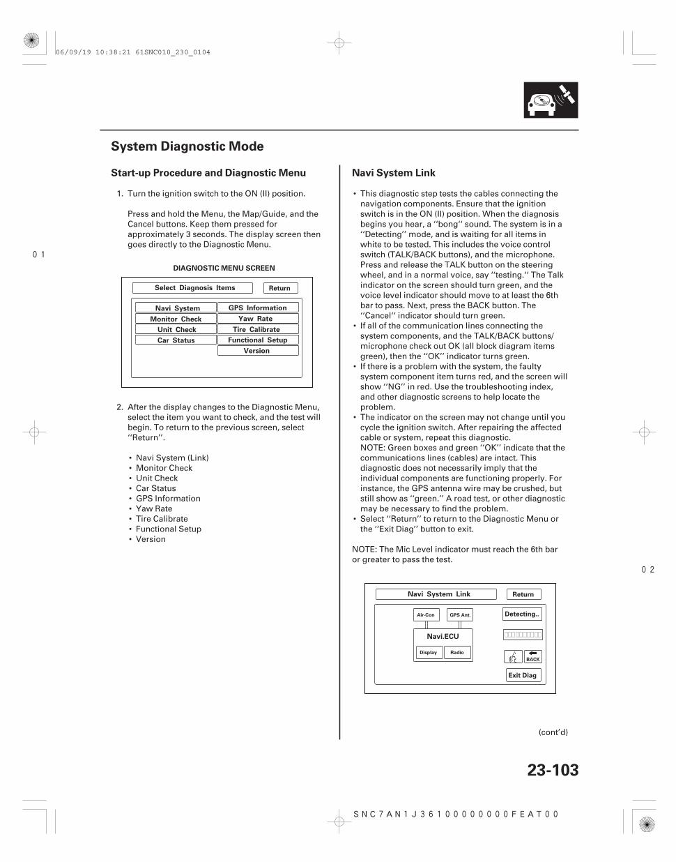
01
02
SNC7AN1J36100000000FEAT00
Start-up Procedure and Diagnostic Menu Navi System Link
23-103
System Diagnostic Mode
Select Diagnosis Items
Navi System
Monitor Check
Unit Check
Car Status
GPS Information
Yaw Rate
Tire Calibrate
Functional Setup
Version
Navi System Link
Navi.ECU
Return
Return
Exit Diag
Detecting..
DIAGNOSTIC MENU SCREEN
GPS Ant.
Display Radio
BACK
Air-Con
1. Turn the ignition switch to the ON (II) position.
Press and hold the Menu, the Map/Guide, and theCancel buttons. Keep them pressed forapproximately 3 seconds. The display screen thengoes directly to the Diagnostic Menu.
2. After the display changes to the Diagnostic Menu,select the item you want to check, and the test willbegin. To return to the previous screen, select‘‘Return’’.
• Navi System (Link)• Monitor Check• Unit Check• Car Status• GPS Information• Yaw Rate• Tire Calibrate• Functional Setup• Version
• This diagnostic step tests the cables connecting thenavigation components. Ensure that the ignitionswitch is in the ON (II) position. When the diagnosisbegins you hear, a ‘‘bong‘‘ sound. The system is in a‘‘Detecting’’ mode, and is waiting for all items inwhite to be tested. This includes the voice controlswitch (TALK/BACK buttons), and the microphone.Press and release the TALK button on the steeringwheel, and in a normal voice, say ‘‘testing.‘‘ The Talkindicator on the screen should turn green, and thevoice level indicator should move to at least the 6thbar to pass. Next, press the BACK button. The‘‘Cancel‘‘ indicator should turn green.
• If all of the communication lines connecting thesystem components, and the TALK/BACK buttons/microphone check out OK (all block diagram itemsgreen), then the ‘‘OK’’ indicator turns green.
• If there is a problem with the system, the faultysystem component item turns red, and the screen willshow ‘‘NG’’ in red. Use the troubleshooting index,and other diagnostic screens to help locate theproblem.
• The indicator on the screen may not change until youcycle the ignition switch. After repairing the affectedcable or system, repeat this diagnostic.NOTE: Green boxes and green ‘‘OK’’ indicate that thecommunications lines (cables) are intact. Thisdiagnostic does not necessarily imply that theindividual components are functioning properly. Forinstance, the GPS antenna wire may be crushed, butstill show as ‘‘green.’’ A road test, or other diagnosticmay be necessary to find the problem.
• Select ‘‘Return’’ to return to the Diagnostic Menu orthe ‘‘Exit Diag’’ button to exit.
NOTE: The Mic Level indicator must reach the 6th baror greater to pass the test.
(cont’d)
06/09/19 10:38:21 61SNC010_230_0104
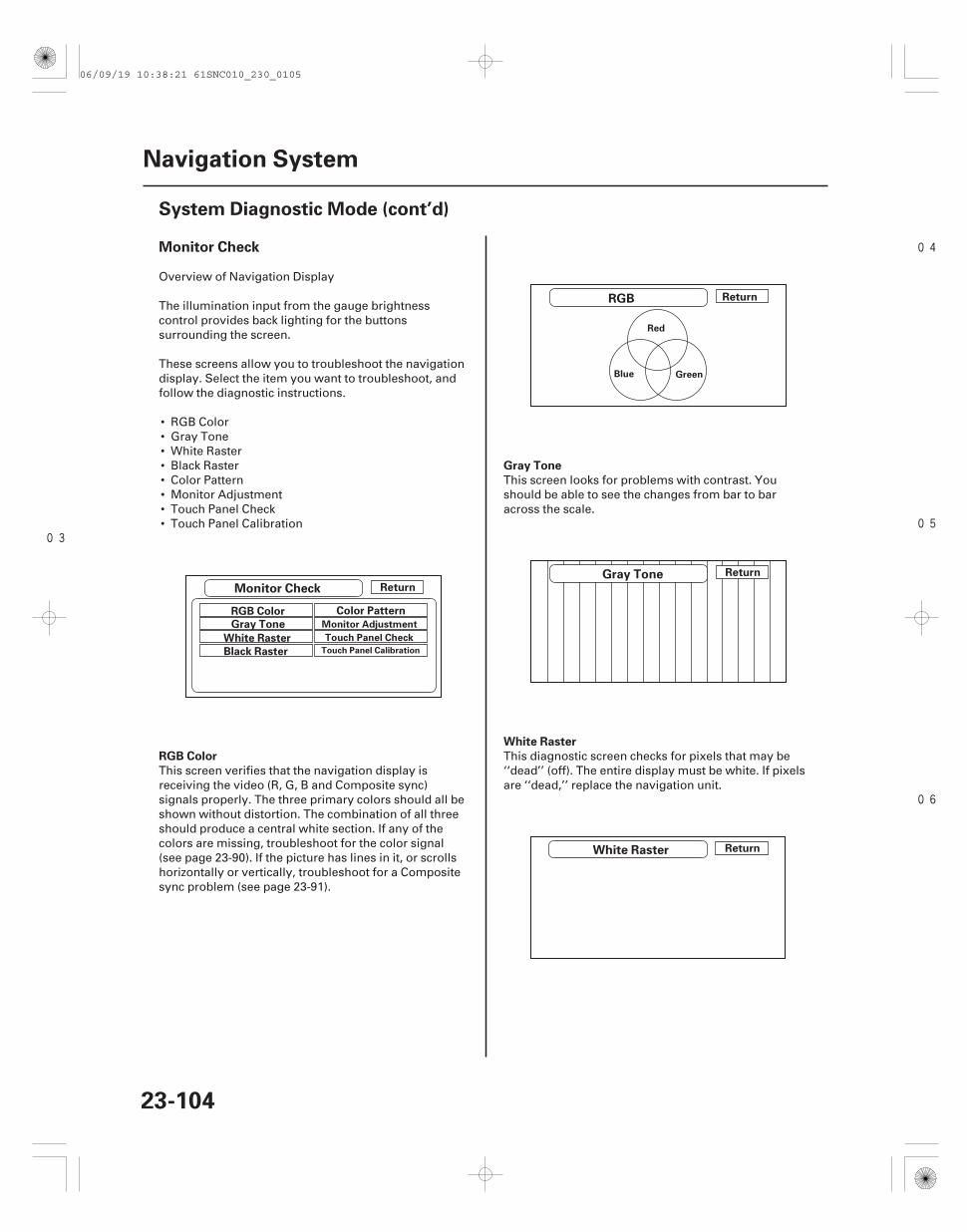
03
04
05
06
Monitor Check
RGB Color
Gray Tone
White Raster
23-104
Navigation System
System Diagnostic Mode (cont’d)
Monitor Check
RGB
Gray Tone
White Raster
Return
RGB Color
Gray Tone
White Raster
Color Pattern
Black Raster
Return
Return
Return
Monitor Adjustment
Touch Panel Check
Touch Panel Calibration
Red
Blue Green
Overview of Navigation Display
The illumination input from the gauge brightnesscontrol provides back lighting for the buttonssurrounding the screen.
These screens allow you to troubleshoot the navigationdisplay. Select the item you want to troubleshoot, andfollow the diagnostic instructions.
• RGB Color• Gray Tone• White Raster• Black Raster• Color Pattern• Monitor Adjustment• Touch Panel Check• Touch Panel Calibration
This screen verifies that the navigation display isreceiving the video (R, G, B and Composite sync)signals properly. The three primary colors should all beshown without distortion. The combination of all threeshould produce a central white section. If any of thecolors are missing, troubleshoot for the color signal(see page 23-90). If the picture has lines in it, or scrollshorizontally or vertically, troubleshoot for a Compositesync problem (see page 23-91).
This screen looks for problems with contrast. Youshould be able to see the changes from bar to baracross the scale.
This diagnostic screen checks for pixels that may be‘‘dead’’ (off). The entire display must be white. If pixelsare ‘‘dead,’’ replace the navigation unit.
06/09/19 10:38:21 61SNC010_230_0105
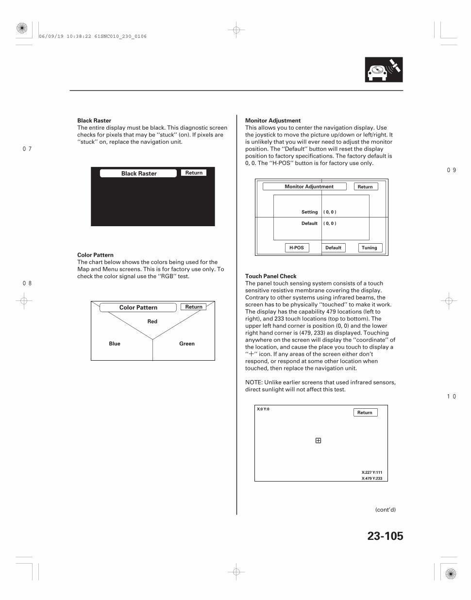
+
07
08
09
10
Black Raster
Color Pattern
Monitor Adjustment
Touch Panel Check
23-105
Black Raster
Color Pattern
Return
Return
Red
GreenBlue
Monitor Adjuntment Return
TuningDefault
( 0, 0 )Default
( 0, 0 )Setting
H-POS
ReturnX:0 Y:0
X:227 Y:111
X:479 Y:233
The entire display must be black. This diagnostic screenchecks for pixels that may be ‘‘stuck’’ (on). If pixels are‘‘stuck’’ on, replace the navigation unit.
The chart below shows the colors being used for theMap and Menu screens. This is for factory use only. Tocheck the color signal use the ‘‘RGB’’ test.
This allows you to center the navigation display. Usethe joystick to move the picture up/down or left/right. Itis unlikely that you will ever need to adjust the monitorposition. The ‘‘Default’’ button will reset the displayposition to factory specifications. The factory default is0, 0. The ‘‘H-POS’’ button is for factory use only.
The panel touch sensing system consists of a touchsensitive resistive membrane covering the display.Contrary to other systems using infrared beams, thescreen has to be physically ‘‘touched’’ to make it work.The display has the capability 479 locations (left toright), and 233 touch locations (top to bottom). Theupper left hand corner is position (0, 0) and the lowerright hand corner is (479, 233) as displayed. Touchinganywhere on the screen will display the ‘‘coordinate’’ ofthe location, and cause the place you touch to display a‘‘ ’’ icon. If any areas of the screen either don’trespond, or respond at some other location whentouched, then replace the navigation unit.
NOTE: Unlike earlier screens that used infrared sensors,direct sunlight will not affect this test.
(cont’d)
06/09/19 10:38:22 61SNC010_230_0106
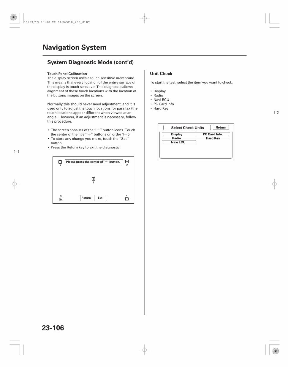
++ -
11
12
+
Touch Panel Calibration Unit Check
23-106
Navigation System
System Diagnostic Mode (cont’d)
Return Set
1 2
3 4
5
Please press the center of’’ ’’button.
Select Check Units Return
Display
Radio
Navi ECU
PC Card Info.
Hard Key
The display screen uses a touch sensitive membrane.This means that every location of the entire surface ofthe display is touch sensitive. This diagnostic allowsalignment of these touch locations with the location ofthe buttons images on the screen.
Normally this should never need adjustment, and it isused only to adjust the touch locations for parallax (thetouch locations appear different when viewed at anangle). However, if an adjustment is necessary, followthis procedure.
• The screen consists of the ‘‘ ’’ button icons. Touchthe center of the five ‘‘ ’’ buttons on order 1 5.
• To store any change you make, touch the ‘‘Set’’button.
• Press the Return key to exit the diagnostic.
To start the test, select the item you want to check.
• Display• Radio• Navi ECU• PC Card Info• Hard Key
06/09/19 10:38:22 61SNC010_230_0107
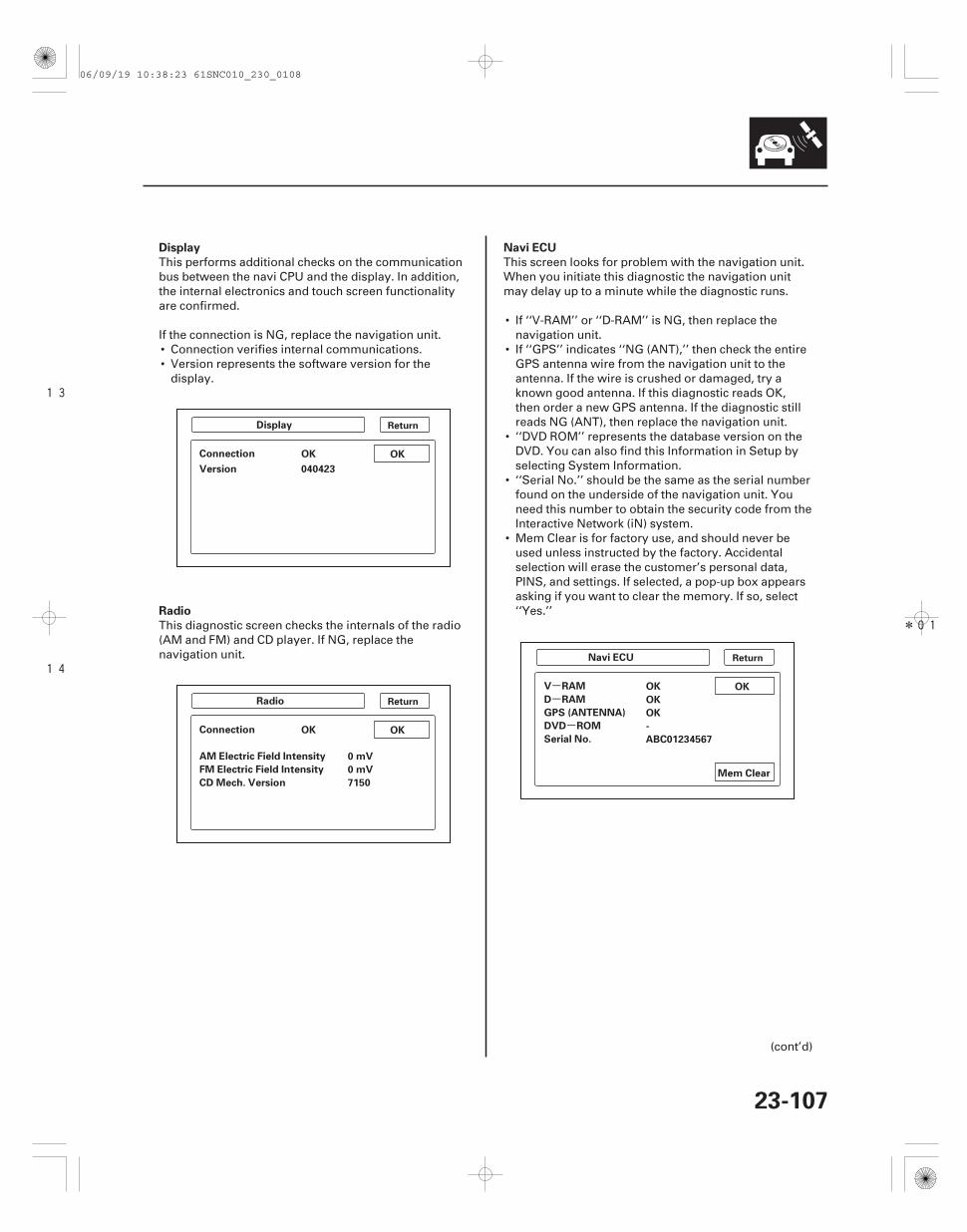
13
14
*01
--
-
Display
Radio
Navi ECU
23-107
Display
OKOKConnection
Version 040423
Radio
OKConnection OK
0 mVAM Electric Field Intensity
0 mVFM Electric Field Intensity
7150CD Mech. Version
Navi ECU
OKV RAM OK
OKD RAM
OKGPS (ANTENNA)
DVD ROM
Serial No. ABC01234567
Mem Clear
-
Return
Return
Return
This performs additional checks on the communicationbus between the navi CPU and the display. In addition,the internal electronics and touch screen functionalityare confirmed.
If the connection is NG, replace the navigation unit.• Connection verifies internal communications.• Version represents the software version for the
display.
This diagnostic screen checks the internals of the radio(AM and FM) and CD player. If NG, replace thenavigation unit.
This screen looks for problem with the navigation unit.When you initiate this diagnostic the navigation unitmay delay up to a minute while the diagnostic runs.
• If ‘‘V-RAM’’ or ‘‘D-RAM’’ is NG, then replace thenavigation unit.
• If ‘‘GPS’’ indicates ‘‘NG (ANT),’’ then check the entireGPS antenna wire from the navigation unit to theantenna. If the wire is crushed or damaged, try aknown good antenna. If this diagnostic reads OK,then order a new GPS antenna. If the diagnostic stillreads NG (ANT), then replace the navigation unit.
• ‘‘DVD ROM’’ represents the database version on theDVD. You can also find this Information in Setup byselecting System Information.
• ‘‘Serial No.’’ should be the same as the serial numberfound on the underside of the navigation unit. Youneed this number to obtain the security code from theInteractive Network (iN) system.
• Mem Clear is for factory use, and should never beused unless instructed by the factory. Accidentalselection will erase the customer’s personal data,PINS, and settings. If selected, a pop-up box appearsasking if you want to clear the memory. If so, select‘‘Yes.’’
(cont’d)
06/09/19 10:38:23 61SNC010_230_0108
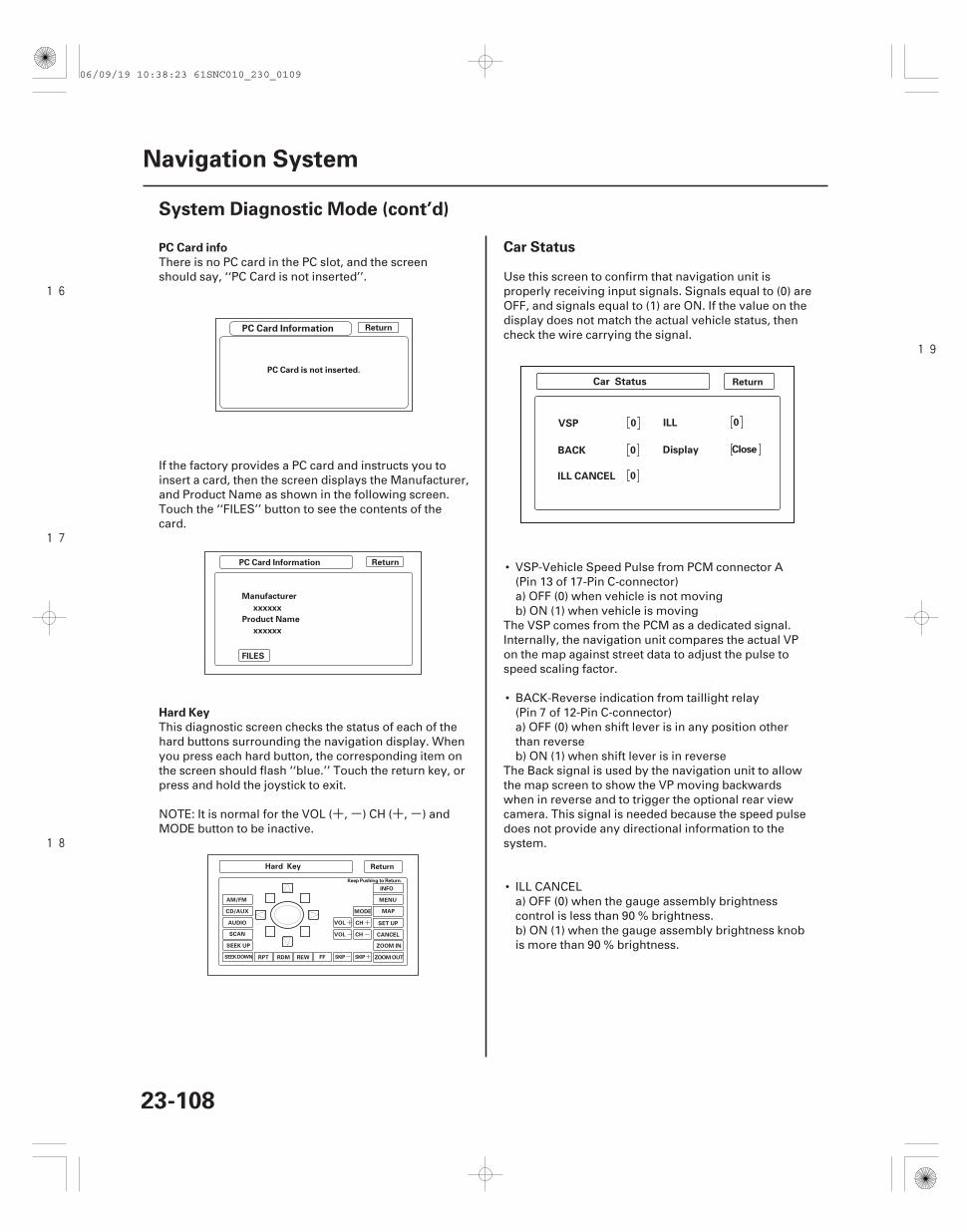
+ - + -
16
17
18
19
+
-
+
-
+-
PC Card info
Hard Key
Car Status
23-108
Navigation System
System Diagnostic Mode (cont’d)
PC Card Information
Return
Return
PC Card is not inserted.
PC Card Information Return
Manufacturer
xxxxxx
Product Name
xxxxxx
FILES
Hard Key Return
ZOOM OUT
ZOOM IN
CANCEL
SET UP
MAP
MENU
INFO
MODE
CH
CH
VOL
VOL
FFREWRPT RDM
SEEK UP
SCAN
AUDIO
CD/AUX
AM/FM
SKIPSKIPSEEKDOWN
Keep Pushing to Return.
Car Status
0VSP 0ILL
0BACK CloseDisplay
0ILL CANCEL
There is no PC card in the PC slot, and the screenshould say, ‘‘PC Card is not inserted’’.
If the factory provides a PC card and instructs you toinsert a card, then the screen displays the Manufacturer,and Product Name as shown in the following screen.Touch the ‘‘FILES’’ button to see the contents of thecard.
This diagnostic screen checks the status of each of thehard buttons surrounding the navigation display. Whenyou press each hard button, the corresponding item onthe screen should flash ‘‘blue.’’ Touch the return key, orpress and hold the joystick to exit.
NOTE: It is normal for the VOL ( , ) CH ( , ) andMODE button to be inactive.
Use this screen to confirm that navigation unit isproperly receiving input signals. Signals equal to (0) areOFF, and signals equal to (1) are ON. If the value on thedisplay does not match the actual vehicle status, thencheck the wire carrying the signal.
• VSP-Vehicle Speed Pulse from PCM connector A(Pin 13 of 17-Pin C-connector)a) OFF (0) when vehicle is not movingb) ON (1) when vehicle is moving
The VSP comes from the PCM as a dedicated signal.Internally, the navigation unit compares the actual VPon the map against street data to adjust the pulse tospeed scaling factor.
• BACK-Reverse indication from taillight relay(Pin 7 of 12-Pin C-connector)a) OFF (0) when shift lever is in any position otherthan reverseb) ON (1) when shift lever is in reverse
The Back signal is used by the navigation unit to allowthe map screen to show the VP moving backwardswhen in reverse and to trigger the optional rear viewcamera. This signal is needed because the speed pulsedoes not provide any directional information to thesystem.
• ILL CANCELa) OFF (0) when the gauge assembly brightnesscontrol is less than 90 % brightness.b) ON (1) when the gauge assembly brightness knobis more than 90 % brightness.
06/09/19 10:38:23 61SNC010_230_0109
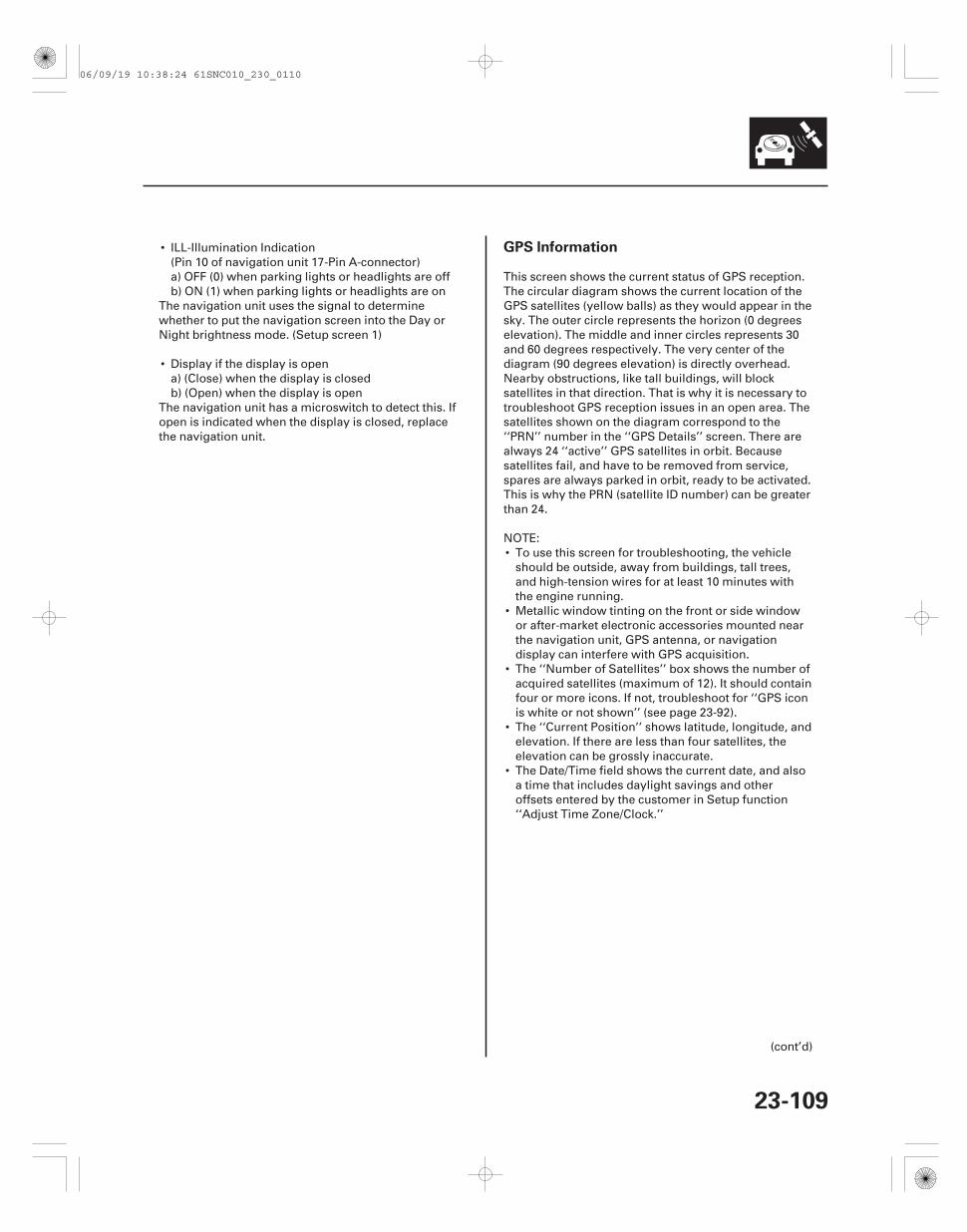
GPS Information
23-109
• ILL-Illumination Indication(Pin 10 of navigation unit 17-Pin A-connector)a) OFF (0) when parking lights or headlights are offb) ON (1) when parking lights or headlights are on
The navigation unit uses the signal to determinewhether to put the navigation screen into the Day orNight brightness mode. (Setup screen 1)
• Display if the display is opena) (Close) when the display is closedb) (Open) when the display is open
The navigation unit has a microswitch to detect this. Ifopen is indicated when the display is closed, replacethe navigation unit.
This screen shows the current status of GPS reception.The circular diagram shows the current location of theGPS satellites (yellow balls) as they would appear in thesky. The outer circle represents the horizon (0 degreeselevation). The middle and inner circles represents 30and 60 degrees respectively. The very center of thediagram (90 degrees elevation) is directly overhead.Nearby obstructions, like tall buildings, will blocksatellites in that direction. That is why it is necessary totroubleshoot GPS reception issues in an open area. Thesatellites shown on the diagram correspond to the‘‘PRN’’ number in the ‘‘GPS Details’’ screen. There arealways 24 ‘‘active’’ GPS satellites in orbit. Becausesatellites fail, and have to be removed from service,spares are always parked in orbit, ready to be activated.This is why the PRN (satellite ID number) can be greaterthan 24.
NOTE:• To use this screen for troubleshooting, the vehicle
should be outside, away from buildings, tall trees,and high-tension wires for at least 10 minutes withthe engine running.
• Metallic window tinting on the front or side windowor after-market electronic accessories mounted nearthe navigation unit, GPS antenna, or navigationdisplay can interfere with GPS acquisition.
• The ‘‘Number of Satellites’’ box shows the number ofacquired satellites (maximum of 12). It should containfour or more icons. If not, troubleshoot for ‘‘GPS iconis white or not shown’’ (see page 23-92).
• The ‘‘Current Position’’ shows latitude, longitude, andelevation. If there are less than four satellites, theelevation can be grossly inaccurate.
• The Date/Time field shows the current date, and alsoa time that includes daylight savings and otheroffsets entered by the customer in Setup function‘‘Adjust Time Zone/Clock.’’
(cont’d)
06/09/19 10:38:24 61SNC010_230_0110
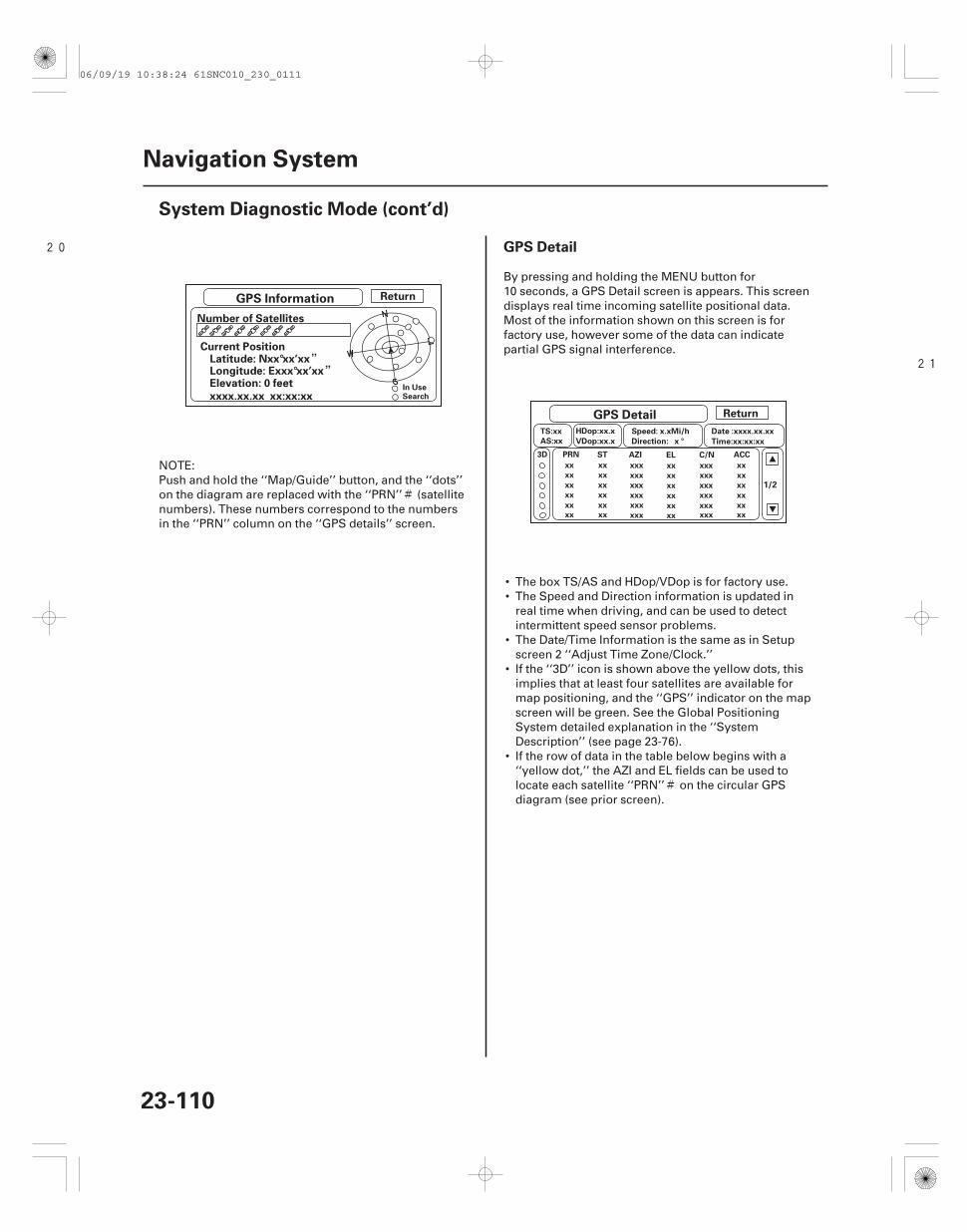
#
#
20
21””
GPS Detail
23-110
Navigation System
System Diagnostic Mode (cont’d)
GPS Information
GPS Detail
Return
Number of Satellites
Current PositionLatitude: Nxx°xx’xx
Elevation: 0 feetLongitude: Exxx°xx’xx
xxxx.xx.xx xx:xx:xx
Return
In UseSearch
TS:xx
AS:xx
HDop:xx.x
VDop:xx.x
Speed: x.xMi/h
Direction: x °
Date :xxxx.xx.xx
Time:xx:xx:xx
xx
PRN
xx
xx
xx
xx
xx
xx
ST
xx
xx
xx
xx
xx
xxx
xxx
xxx
xxx
xxx
xxx
AZI
xx
EL
xx
xx
xx
xx
xx
xxx
C/N
xxx
xxx
xxx
xxx
xxx
xx
ACC
xx
xx
xx
xx
xx
3D
1/2
NOTE:Push and hold the ‘‘Map/Guide’’ button, and the ‘‘dots’’on the diagram are replaced with the ‘‘PRN’’ (satellitenumbers). These numbers correspond to the numbersin the ‘‘PRN’’ column on the ‘‘GPS details’’ screen.
By pressing and holding the MENU button for10 seconds, a GPS Detail screen is appears. This screendisplays real time incoming satellite positional data.Most of the information shown on this screen is forfactory use, however some of the data can indicatepartial GPS signal interference.
• The box TS/AS and HDop/VDop is for factory use.• The Speed and Direction information is updated in
real time when driving, and can be used to detectintermittent speed sensor problems.
• The Date/Time Information is the same as in Setupscreen 2 ‘‘Adjust Time Zone/Clock.’’
• If the ‘‘3D’’ icon is shown above the yellow dots, thisimplies that at least four satellites are available formap positioning, and the ‘‘GPS’’ indicator on the mapscreen will be green. See the Global PositioningSystem detailed explanation in the ‘‘SystemDescription’’ (see page 23-76).
• If the row of data in the table below begins with a‘‘yellow dot,’’ the AZI and EL fields can be used tolocate each satellite ‘‘PRN’’ on the circular GPSdiagram (see prior screen).
06/09/19 10:38:24 61SNC010_230_0111
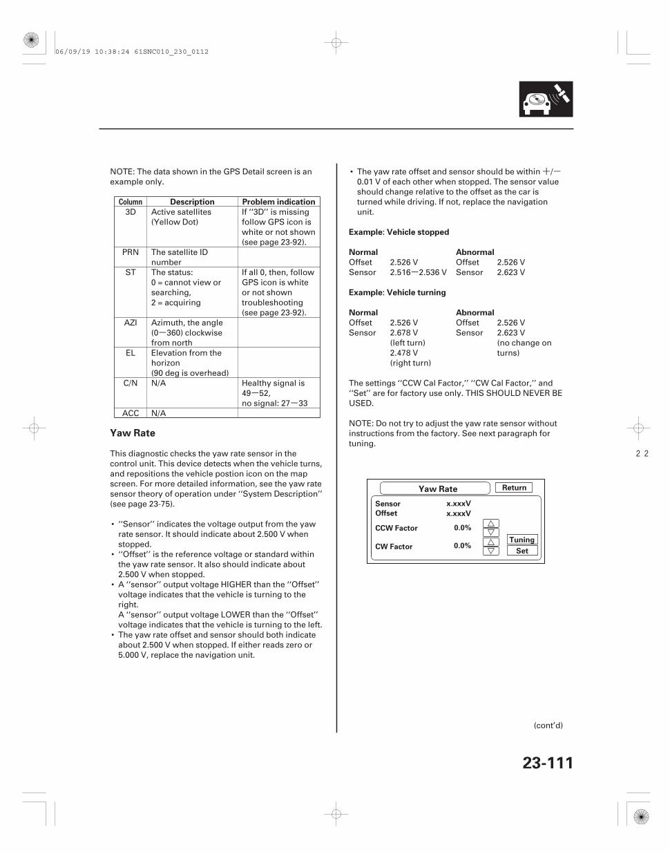
-
--
+-
-
22
Column Description Problem indication
Example: Vehicle stopped
Normal Abnormal
Example: Vehicle turning
Normal Abnormal
Yaw Rate
23-111
Yaw Rate Return
Sensor
Offset
CCW Factor
CW Factor
x.xxxV
x.xxxV
0.0%
0.0%Set
Tuning
NOTE: The data shown in the GPS Detail screen is anexample only.
3D Active satellites(Yellow Dot)
If ‘‘3D’’ is missingfollow GPS icon iswhite or not shown(see page 23-92).
PRN The satellite IDnumber
ST The status:0 = cannot view orsearching,2 = acquiring
If all 0, then, followGPS icon is whiteor not showntroubleshooting(see page 23-92).
AZI Azimuth, the angle(0 360) clockwisefrom north
EL Elevation from thehorizon(90 deg is overhead)
C/N N/A Healthy signal is49 52,no signal: 27 33
ACC N/A
This diagnostic checks the yaw rate sensor in thecontrol unit. This device detects when the vehicle turns,and repositions the vehicle postion icon on the mapscreen. For more detailed information, see the yaw ratesensor theory of operation under ‘‘System Description’’(see page 23-75).
• ‘‘Sensor’’ indicates the voltage output from the yawrate sensor. It should indicate about 2.500 V whenstopped.
• ‘‘Offset’’ is the reference voltage or standard withinthe yaw rate sensor. It also should indicate about2.500 V when stopped.
• A ‘‘sensor’’ output voltage HIGHER than the ‘‘Offset’’voltage indicates that the vehicle is turning to theright.A ‘‘sensor’’ output voltage LOWER than the ‘‘Offset’’voltage indicates that the vehicle is turning to the left.
• The yaw rate offset and sensor should both indicateabout 2.500 V when stopped. If either reads zero or5.000 V, replace the navigation unit.
• The yaw rate offset and sensor should be within /0.01 V of each other when stopped. The sensor valueshould change relative to the offset as the car isturned while driving. If not, replace the navigationunit.
Offset 2.526 V Offset 2.526 VSensor 2.516 2.536 V Sensor 2.623 V
Offset 2.526 V Offset 2.526 VSensor 2.678 V
(left turn)2.478 V(right turn)
Sensor 2.623 V(no change onturns)
The settings ‘‘CCW Cal Factor,’’ ‘‘CW Cal Factor,’’ and‘‘Set’’ are for factory use only. THIS SHOULD NEVER BEUSED.
NOTE: Do not try to adjust the yaw rate sensor withoutinstructions from the factory. See next paragraph fortuning.
(cont’d)
06/09/19 10:38:24 61SNC010_230_0112
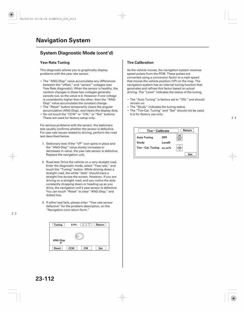
23
24
-
-
Yaw Rate Tuning Tire Calibration
23-112
Navigation System
System Diagnostic Mode (cont’d)
Return
SetReset CCW CW
Tuning 0.0%
ANG-Disp0°
Tire Calibrate Return
Auto Tuning OFF
Level0
xx.xx%
Set
Study
Tire Cal. Tuning
ON
OFF
This diagnostic allows you to graphically displayproblems with the yaw rate sensor.
• The ‘‘ANG-Disp’’ value accumulates any differencesbetween the ‘‘offset,’’ and ‘‘sensor’’ voltages (seeYaw Rate diagnostic). When the sensor is healthy, therandom changes in these two voltages generallycancels out, so the value is 0. However if one voltageis consistently higher than the other, then the ‘‘ANG-Disp’’ value accumulates the constant change.
• The ‘‘Reset’’ button temporarily clears the angularaccumulation (ANG-Disp), and clears the display dots.
• Do not touch the ‘‘CCW’’ or ‘‘CW,’’ or ‘‘Set’’ buttons.These are used for factory setup only.
For serious problems with the sensor, the stationarytest usually confirms whether the sensor is defective.For yaw rate issues related to driving, perform the roadtest described below.
1. Stationary test: If the ‘‘VP’’ icon spins in place andthe ‘‘ANG-Disp’’ value slowly increases ordecreases in value, the yaw rate sensor is defective.Replace the navigation unit.
2. Road test: Drive the vehicle on a very straight road.Enter the diagnostic mode, select ‘‘Yaw rate,’’ andtouch the ‘‘Tuning’’ button. While driving down astraight road, the white ‘‘dots’’ should trace astraight line across the screen. However, if you aredriving on a straight road, and you notice the dotsconstantly dropping down or heading up as youdrive, the navigation unit’s yaw sensor is defective.You can touch ‘‘Reset’’ to clear ‘‘ANG-Disp,’’ anddotted line.
3. If either test fails, please enter ‘‘Yaw rate sensordefective’’ for the problem description, on the‘‘Navigation core return form.’’
As the vehicle moves, the navigation system receivesspeed pulses from the PCM. These pulses areconverted using a conversion factor to a mph speedthat moves the vehicle position (VP) on the map. Thenavigation system has an internal tuning function thatgenerates and refines this factor based on actualdriving. The ‘‘Level’’ indicates the status of the tuning.
• The ‘‘Auto Tuning’’ is factory set to ‘‘ON,’’ and shouldremain on.
• The ‘‘Study’’ indicates the tuning status.• The ‘‘Tire-Cal. Tuning’’ and ‘‘Set’’ should not be used.
It is for factory use only.
06/09/19 10:38:25 61SNC010_230_0113
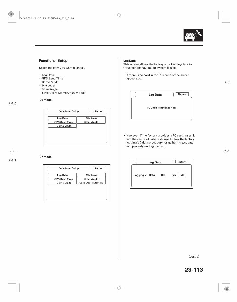
*02
*03
26
27
Functional Setup
’06 model
’07 model
Log Data
23-113
Functional Setup
Log Data
GPS Send Time
Demo Mode
Mic Level
Solar Angle
Functional Setup
Log Data
GPS Send Time
Demo Mode
Mic Level
Solar Angle
Save Users Memory
Return
Return
Log Data
Log Data
Return
PC Card is not inserted.
Return
Logging VP Data OFF ON OFF
Select the item you want to check.
• Log Data• GPS Send Time• Demo Mode• Mic Level• Solar Angle• Save Users Memory (’07 model)
This screen allows the factory to collect log data totroubleshoot navigation system issues.
• If there is no card in the PC card slot the screenappears as:
• However, if the factory provides a PC card, insert itinto the card slot (label side up). Follow the factorylogging VD data procedure for gathering test dataand properly ending the test.
(cont’d)
06/09/19 10:38:25 61SNC010_230_0114
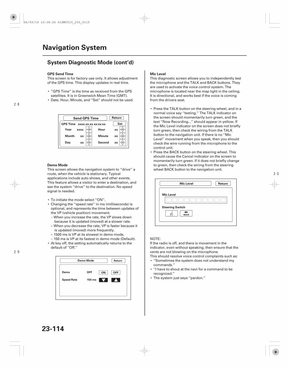
28
29
30
GPS Send Time
Demo Mode
Mic Level
23-114
Navigation System
System Diagnostic Mode (cont’d)
Send GPS Time Return
GPS Time
Second
Year
Day
Hour
Minute
xxxx.xx.xx xx:xx:xx Set
xxxx
xx
Month xx
xx
xx
xx
Demo Mode
OFFDemo
Speed Rate 150 ms
ON OFF
Return
Return
Steering Switch
Mic Level
Mic Level
BACK
This screen is for factory use only. It allows adjustmentof the GPS time. This display updates in real time.
• ‘‘GPS Time’’ is the time as received from the GPSsatellites. It is in Greenwich Mean Time (GMT).
• Date, Hour, Minute, and ‘‘Set’’ should not be used.
This screen allows the navigation system to ‘‘drive’’ aroute, when the vehicle is stationary. Typicalapplications include auto shows, and other events.This feature allows a visitor to enter a destination, andsee the system ‘‘drive’’ to the destination. No speedsignal is needed.
• To initiate the mode select ‘‘ON’’.• Changing the ‘‘speed rate’’ in ms (milliseconds) is
optional, and represents the time between updates ofthe VP (vehicle position) movement.– When you increase the rate, the VP slows down
because it is updated (moved) at a slower rate.– When you decrease the rate, VP is faster because it
is updated (moved) more frequently.– 1500 ms is VP at its slowest in demo mode.– 150 ms is VP at its fastest in demo mode (Default).
• At key off, the setting automatically returns to thedefault of ‘‘Off.’’
This diagnostic screen allows you to independently testthe microphone and the TALK and BACK buttons. Theyare used to activate the voice control system. Themicrophone is located near the map light in the ceiling.It is directional, and works best if the voice is comingfrom the drivers seat.
• Press the TALK button on the steering wheel, and in anormal voice say ‘‘testing.’’ The TALK indicator onthe screen should momentarily turn green, and thetext ‘‘Now Recording...’’ should appear in yellow. Ifthe Mic Level indicator on the screen does not brieflyturn green, then check the wiring from the TALKbutton to the navigation unit. If there is no ‘‘MicLevel’’ movement when you speak, then you shouldcheck the wire running from the microphone to thecontrol unit.
• Press the BACK button on the steering wheel. Thisshould cause the Cancel indicator on the screen tomomentarily turn green. If it does not briefly changeto green, then check the wiring from the steeringwheel BACK button to the navigation unit.
NOTE:If the radio is off, and there is movement in theindicator, even without speaking, then ensure that thevents are not blowing on the microphone.This should resolve voice control complaints such as:• ‘‘Sometimes the system does not understand my
commands.’’• ‘‘I have to shout at the navi for a command to be
recognized.’’• The system just says ‘‘pardon.’’
06/09/19 10:38:26 61SNC010_230_0115
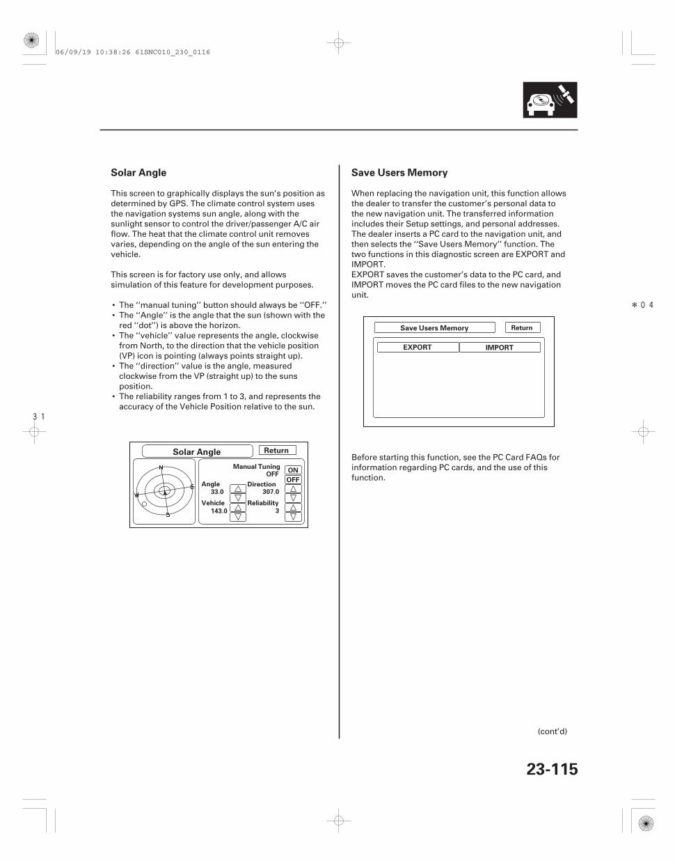
31
*04
Solar Angle Save Users Memory
23-115
Solar Angle
Manual Tuning
Angle Direction
Reliability
33.0
Vehicle
143.0
307.0
3
OFFON
Return
Return
OFF
EXPORT IMPORT
Save Users Memory
This screen to graphically displays the sun’s position asdetermined by GPS. The climate control system usesthe navigation systems sun angle, along with thesunlight sensor to control the driver/passenger A/C airflow. The heat that the climate control unit removesvaries, depending on the angle of the sun entering thevehicle.
This screen is for factory use only, and allowssimulation of this feature for development purposes.
• The ‘‘manual tuning’’ button should always be ‘‘OFF.’’• The ‘‘Angle’’ is the angle that the sun (shown with the
red ‘‘dot’’) is above the horizon.• The ‘‘vehicle’’ value represents the angle, clockwise
from North, to the direction that the vehicle position(VP) icon is pointing (always points straight up).
• The ‘‘direction’’ value is the angle, measuredclockwise from the VP (straight up) to the sunsposition.
• The reliability ranges from 1 to 3, and represents theaccuracy of the Vehicle Position relative to the sun.
When replacing the navigation unit, this function allowsthe dealer to transfer the customer’s personal data tothe new navigation unit. The transferred informationincludes their Setup settings, and personal addresses.The dealer inserts a PC card to the navigation unit, andthen selects the ‘‘Save Users Memory’’ function. Thetwo functions in this diagnostic screen are EXPORT andIMPORT.EXPORT saves the customer’s data to the PC card, andIMPORT moves the PC card files to the new navigationunit.
Before starting this function, see the PC Card FAQs forinformation regarding PC cards, and the use of thisfunction.
(cont’d)
06/09/19 10:38:26 61SNC010_230_0116
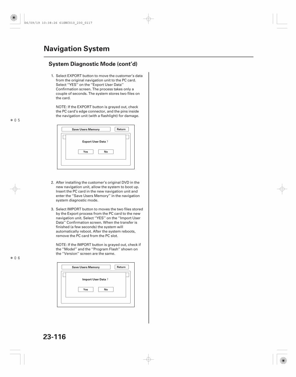
*05
*06
?
?
23-116
Navigation System
System Diagnostic Mode (cont’d)
Return
Yes No
Return
Yes No
Save Users Memory
Export User Data
Save Users Memory
Import User Data
1. Select EXPORT button to move the customer’s datafrom the original navigation unit to the PC card.Select ‘‘YES’’ on the ‘‘Export User Data’’Confirmation screen. The process takes only acouple of seconds. The system stores two files onthe card.
NOTE: If the EXPORT button is grayed out, checkthe PC card’s edge connector, and the pins insidethe navigation unit (with a flashlight) for damage.
2. After installing the customer’s original DVD in thenew navigation unit, allow the system to boot up.Insert the PC card in the new navigation unit andenter the ‘‘Save Users Memory’’ in the navigationsystem diagnostic mode.
3. Select IMPORT button to moves the two files storedby the Export process from the PC card to the newnavigation unit. Select ‘‘YES’’ on the ‘‘Import UserData’’ Confirmation screen. When the transfer isfinished (a few seconds) the system willautomatically reboot. After the system reboots,remove the PC card from the PC slot.
NOTE: If the IMPORT button is grayed out, check ifthe ‘‘Model’’ and the ‘‘Program Flash’’ shown onthe ‘‘Version’’ screen are the same.
06/09/19 10:38:26 61SNC010_230_0117
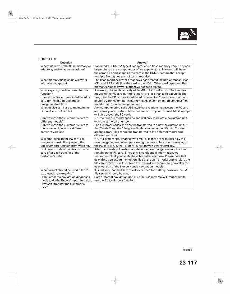
PC Card FAQs
Question Answer
23-117
Where do we buy the flash memory oradaptors, and what do we ask for?
You need a ‘‘PCMCIA type II’’ adaptor and a flash memory chip. They canbe purchased at a computer, or office supply store. The card will havethe same size and shape as the card in the HDS. Adaptors that acceptmultiple flash types are not recommended.
What memory flash chips will workwith what adaptors?
The flash memory devices that have been tested include Compact Flash(CF), and ATA style (like the card in the HDS). Other card types and flashmemory chips may work, but have not been tested.
What capacity card do I need for thisfunction?
A memory chip with capacity of 64 MB to 2 GB will work. The two filesmoved to the PC card during ‘‘export’’ are less than a Megabyte in size.
Should the dealer have a dedicated PCcard for the Export and Importnavigation function?
Yes, treat the PC card as a dedicated ‘‘special tool’’ that should be usedanytime your ’07 or later customer needs their navigation personal filestransferred to a new navigation unit.
What device can I use to maintain thePC card, and delete files
Any computer store sells USB style card readers that accept the PC card,and allow you to perform file maintenance on your PC card. Most laptopswill also accept the PC card.
Can we move the customer’s data todifferent models?
No, the files are model specific and will only load into a navigation unitwith the same part number.
Can we move the customer’s data tothe same vehicle with a differentsoftware version?
The customer’s files can only be transferred to a new navigation unit, ifthe ‘‘Model’’ and the ‘‘Program Flash’’ shown on the ‘‘Version’’ screenare the same. Files cannot be transferred to the different model anddifferent versions.
Will other files on the PC card likeimages or music files prevent theExport/Import function from working?
No, the system simply adds two small files that are recognized by thenew navigation unit when performing the Import function. However, ifthe PC card is full, the ‘‘Export’’ function won’t work correctly.
Do I have to delete the files on the PCcard after each transfer of thecustomer’s data?
After the transfer of customer data to the new navigation unit, the filesremain on the PC card. Since this is confidential information, werecommend that you delete these files after each use. Please note thateach time you export navigation files of the same model and version, thefiles are overwritten. Over time the PC card will accumulate two files foreach version of the 8 or so Honda navigation models.
What format should be used if the PCcard needs reformatting?
It is unlikely that the PC card will ever need formatting, however the FATfile system should be used.
I can’t enter the navigation diagnosticmode to do the Export/Import function.How can I transfer the customer’sdata?
Some internal navigation unit ECU failures may make it impossible touse the Export/Import function.
(cont’d)
06/09/19 10:38:27 61SNC010_230_0118
Question Answer
23-118
Navigation System
System Diagnostic Mode (cont’d)
•
•
•
•
•
•
•
•
•
•
•
•
Why wont the Export or Importfunctions work?What do I check as part oftroubleshooting?
The card may not be fully inserted into the slot. Eject the PC card, andinspect for warping or damage to the edge connector. Never useexcessive force to insert a PC card. This can result in damage to thepins in the rear of the slot.The PC card may not contain files that are recognized by the newnavigation unit. Navigation data can only be transferred betweennavigation units with the same ‘‘Model code’’, and with the same navi‘‘Program flash’’ version.The flash memory chip type may not be accepted by the system. OnlyCompact Flash, and ATA cards have been tested.The card’s PCMCIA adaptor may be preventing a known-good PC cardfrom playing. Avoid multi slot type PCMCIA adaptors that acceptseveral different flash memory types.The card may be full and as a result the files are stored, but withoutany data. Export and import appear to function, but move nothing.Delete unused files from the PC card.There may not be any files on the PC card. If the card has a ‘‘writeprotection’’ switch, make sure it is turned off before attempting to usethe Export function.Although flash memory chips are reliable, occasionally they developbad sectors or other formatting errors that prevents them fromaccepting files. The PC card should be reformatted using the FATformat.The PC card may have been formatting using the format ‘‘NTFS’’. Onlythe ‘‘FAT’’ format is accepted by the system.Hard Disc Drive (HDD) cards may not work properly in the system andcan overheat or quit functioning, particularly in a hot vehicle. They arenot recommended.Before performing the Import function, ensure that the customer’soriginal DVD is loaded into the new navigation unit and workingproperly.
06/09/19 10:38:27 61SNC010_230_0119
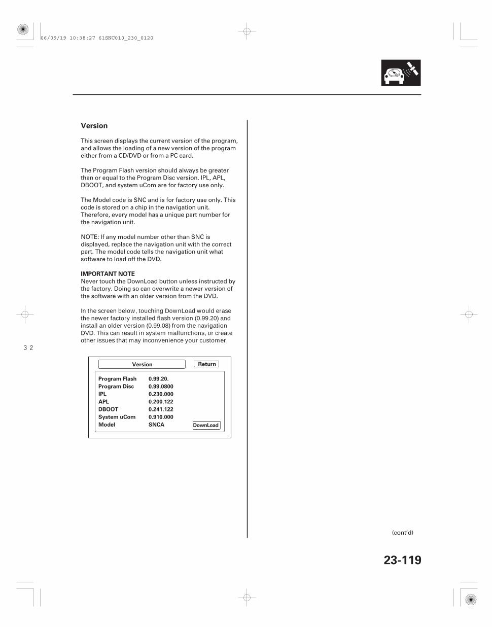
32
Version
IMPORTANT NOTE
23-119
Version Return
Program Flash 0.99.20.
Program Disc 0.99.0800
IPL 0.230.000
APL 0.200.122
DBOOT 0.241.122
System uCom 0.910.000
Model SNCA DownLoad
This screen displays the current version of the program,and allows the loading of a new version of the programeither from a CD/DVD or from a PC card.
The Program Flash version should always be greaterthan or equal to the Program Disc version. IPL, APL,DBOOT, and system uCom are for factory use only.
The Model code is SNC and is for factory use only. Thiscode is stored on a chip in the navigation unit.Therefore, every model has a unique part number forthe navigation unit.
NOTE: If any model number other than SNC isdisplayed, replace the navigation unit with the correctpart. The model code tells the navigation unit whatsoftware to load off the DVD.
Never touch the DownLoad button unless instructed bythe factory. Doing so can overwrite a newer version ofthe software with an older version from the DVD.
In the screen below, touching DownLoad would erasethe newer factory installed flash version (0.99.20) andinstall an older version (0.99.08) from the navigationDVD. This can result in system malfunctions, or createother issues that may inconvenience your customer.
(cont’d)
06/09/19 10:38:27 61SNC010_230_0120
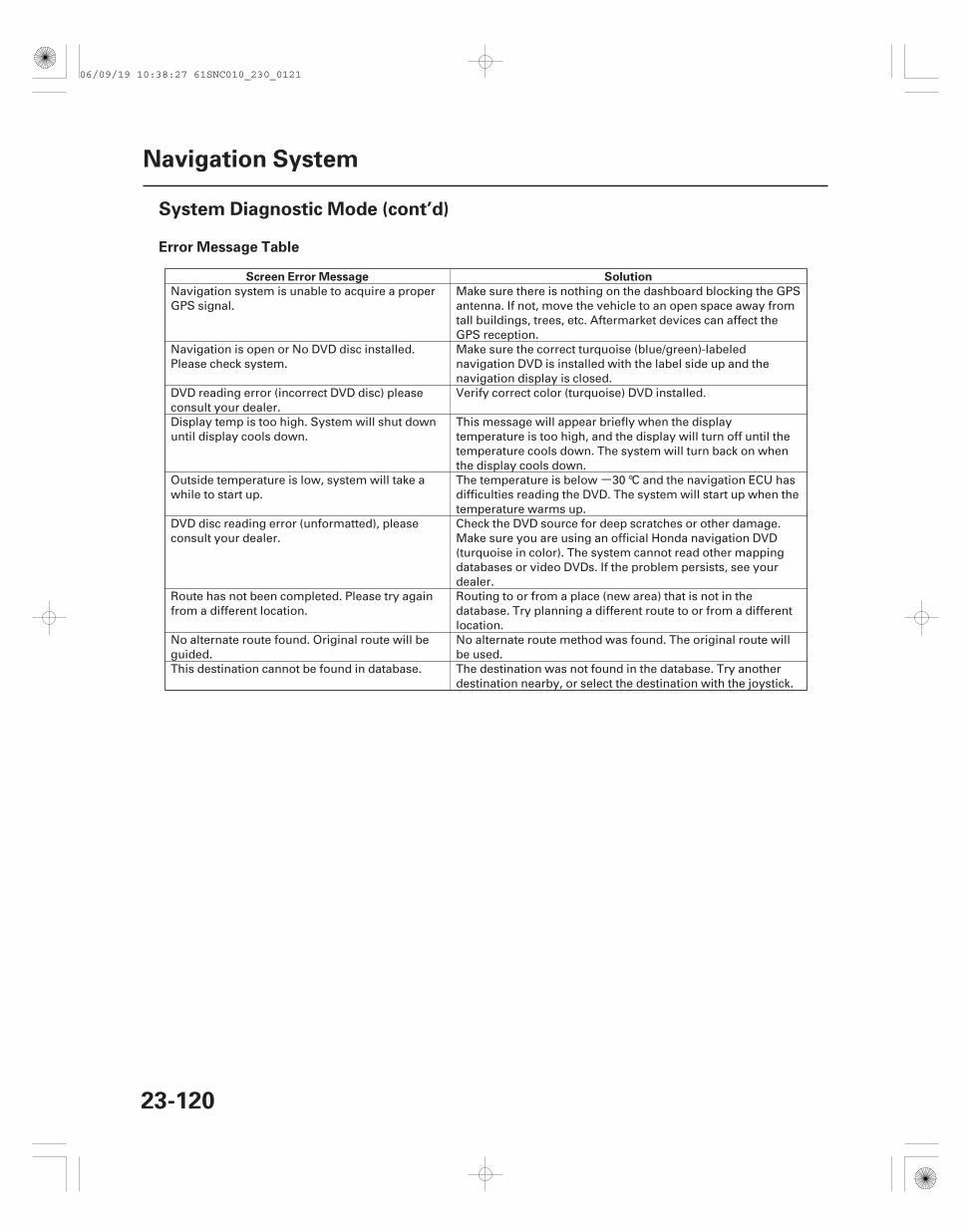
-
Error Message Table
Screen Error Message Solution
23-120
Navigation System
System Diagnostic Mode (cont’d)
Navigation system is unable to acquire a properGPS signal.
Make sure there is nothing on the dashboard blocking the GPSantenna. If not, move the vehicle to an open space away fromtall buildings, trees, etc. Aftermarket devices can affect theGPS reception.
Navigation is open or No DVD disc installed.Please check system.
Make sure the correct turquoise (blue/green)-labelednavigation DVD is installed with the label side up and thenavigation display is closed.
DVD reading error (incorrect DVD disc) pleaseconsult your dealer.
Verify correct color (turquoise) DVD installed.
Display temp is too high. System will shut downuntil display cools down.
This message will appear briefly when the displaytemperature is too high, and the display will turn off until thetemperature cools down. The system will turn back on whenthe display cools down.
Outside temperature is low, system will take awhile to start up.
The temperature is below 30 °C and the navigation ECU hasdifficulties reading the DVD. The system will start up when thetemperature warms up.
DVD disc reading error (unformatted), pleaseconsult your dealer.
Check the DVD source for deep scratches or other damage.Make sure you are using an official Honda navigation DVD(turquoise in color). The system cannot read other mappingdatabases or video DVDs. If the problem persists, see yourdealer.
Route has not been completed. Please try againfrom a different location.
Routing to or from a place (new area) that is not in thedatabase. Try planning a different route to or from a differentlocation.
No alternate route found. Original route will beguided.
No alternate route method was found. The original route willbe used.
This destination cannot be found in database. The destination was not found in the database. Try anotherdestination nearby, or select the destination with the joystick.
06/09/19 10:38:27 61SNC010_230_0121
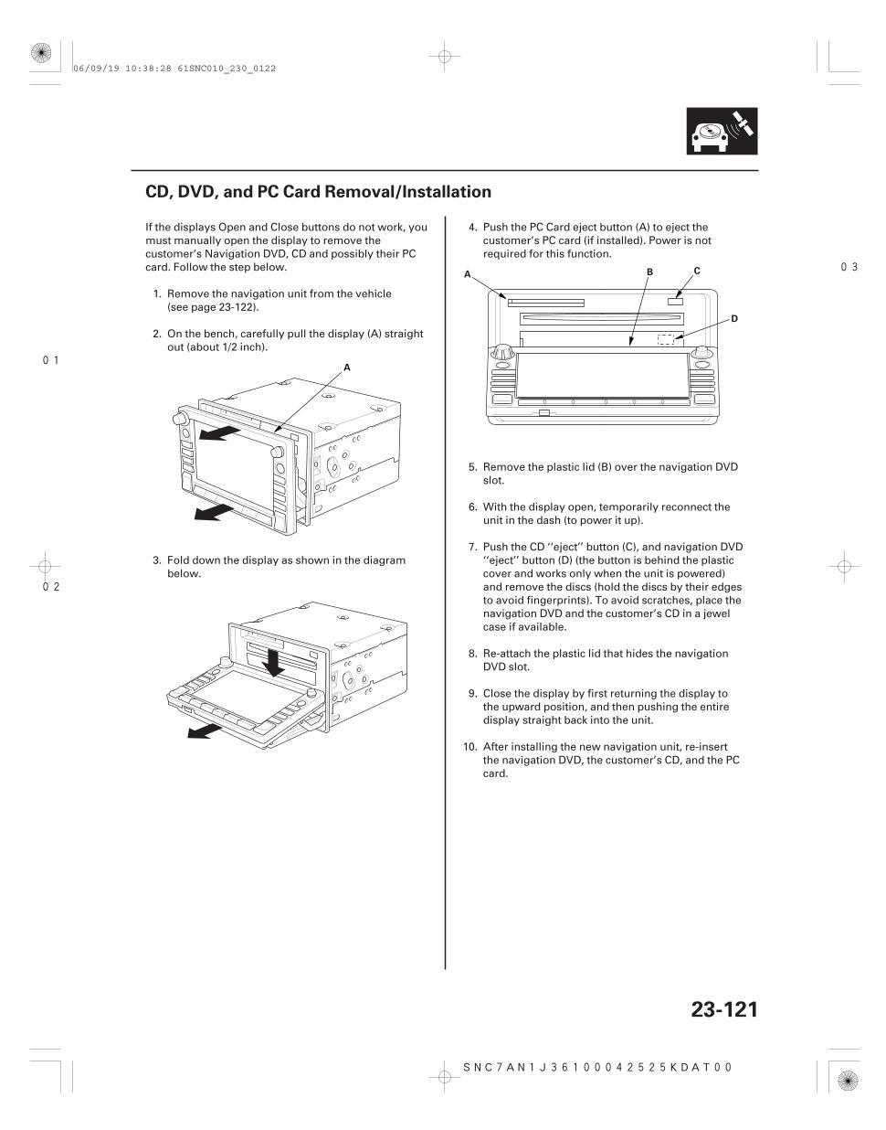
01
02
03
SNC7AN1J36100042525KDAT00
23-121
CD, DVD, and PC Card Removal/Installation
A
A B C
D
If the displays Open and Close buttons do not work, youmust manually open the display to remove thecustomer’s Navigation DVD, CD and possibly their PCcard. Follow the step below.
1. Remove the navigation unit from the vehicle(see page 23-122).
2. On the bench, carefully pull the display (A) straightout (about 1/2 inch).
3. Fold down the display as shown in the diagrambelow.
4. Push the PC Card eject button (A) to eject thecustomer’s PC card (if installed). Power is notrequired for this function.
5. Remove the plastic lid (B) over the navigation DVDslot.
6. With the display open, temporarily reconnect theunit in the dash (to power it up).
7. Push the CD ‘‘eject’’ button (C), and navigation DVD‘‘eject’’ button (D) (the button is behind the plasticcover and works only when the unit is powered)and remove the discs (hold the discs by their edgesto avoid fingerprints). To avoid scratches, place thenavigation DVD and the customer’s CD in a jewelcase if available.
8. Re-attach the plastic lid that hides the navigationDVD slot.
9. Close the display by first returning the display tothe upward position, and then pushing the entiredisplay straight back into the unit.
10. After installing the new navigation unit, re-insertthe navigation DVD, the customer’s CD, and the PCcard.
06/09/19 10:38:28 61SNC010_230_0122
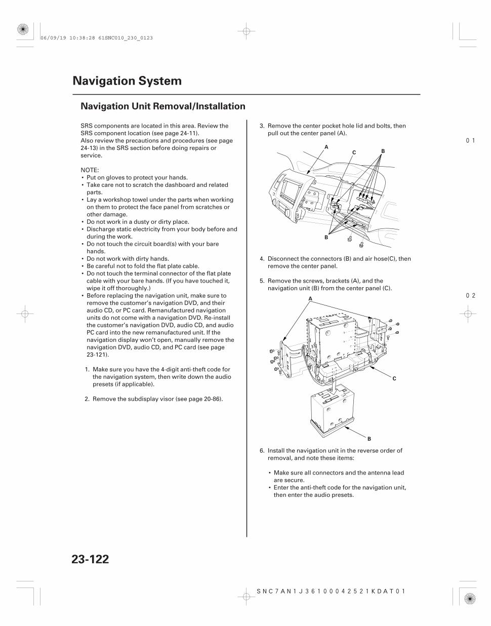
01
02
SNC7AN1J36100042521KDAT01
23-122
Navigation System
Navigation Unit Removal/Installation
A
B
BC
A
B
C
SRS components are located in this area. Review theSRS component location (see page 24-11).Also review the precautions and procedures (see page24-13) in the SRS section before doing repairs orservice.
NOTE:• Put on gloves to protect your hands.• Take care not to scratch the dashboard and related
parts.• Lay a workshop towel under the parts when working
on them to protect the face panel from scratches orother damage.
• Do not work in a dusty or dirty place.• Discharge static electricity from your body before and
during the work.• Do not touch the circuit board(s) with your bare
hands.• Do not work with dirty hands.• Be careful not to fold the flat plate cable.• Do not touch the terminal connector of the flat plate
cable with your bare hands. (If you have touched it,wipe it off thoroughly.)
• Before replacing the navigation unit, make sure toremove the customer’s navigation DVD, and theiraudio CD, or PC card. Remanufactured navigationunits do not come with a navigation DVD. Re-installthe customer’s navigation DVD, audio CD, and audioPC card into the new remanufactured unit. If thenavigation display won’t open, manually remove thenavigation DVD, audio CD, and PC card (see page23-121).
1. Make sure you have the 4-digit anti-theft code forthe navigation system, then write down the audiopresets (if applicable).
2. Remove the subdisplay visor (see page 20-86).
3. Remove the center pocket hole lid and bolts, thenpull out the center panel (A).
4. Disconnect the connectors (B) and air hose(C), thenremove the center panel.
5. Remove the screws, brackets (A), and thenavigation unit (B) from the center panel (C).
6. Install the navigation unit in the reverse order ofremoval, and note these items:
• Make sure all connectors and the antenna leadare secure.
• Enter the anti-theft code for the navigation unit,then enter the audio presets.
06/09/19 10:38:28 61SNC010_230_0123
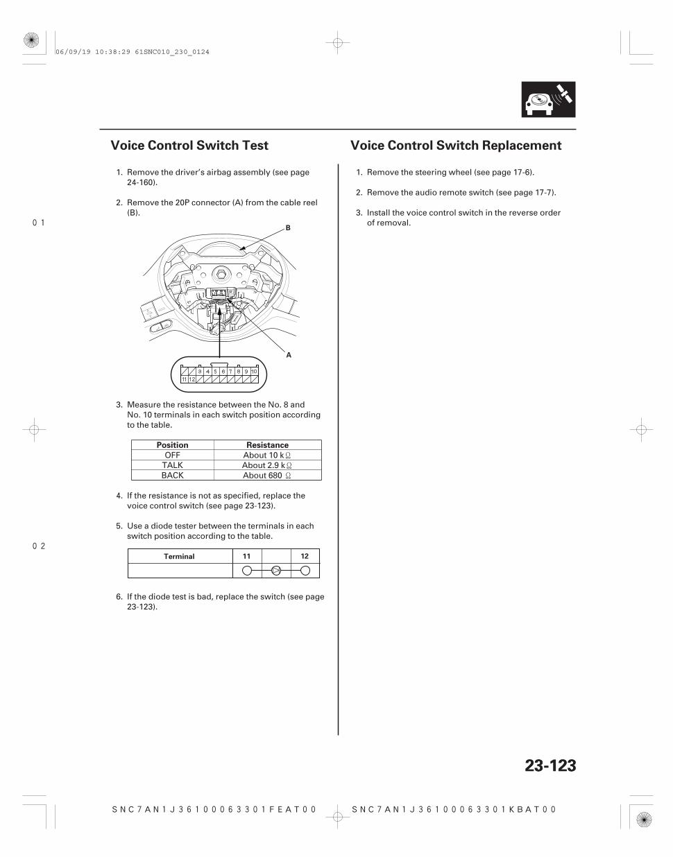
01
02
SNC7AN1J36100063301FEAT00 SNC7AN1J36100063301KBAT00
Position Resistance
23-12323-123
Voice Control Switch Test Voice Control Switch Replacement
A
B
Terminal 11 12
1. Remove the driver’s airbag assembly (see page24-160).
2. Remove the 20P connector (A) from the cable reel(B).
3. Measure the resistance between the No. 8 andNo. 10 terminals in each switch position accordingto the table.
OFF About 10 kTALK About 2.9 kBACK About 680
4. If the resistance is not as specified, replace thevoice control switch (see page 23-123).
5. Use a diode tester between the terminals in eachswitch position according to the table.
6. If the diode test is bad, replace the switch (see page23-123).
1. Remove the steering wheel (see page 17-6).
2. Remove the audio remote switch (see page 17-7).
3. Install the voice control switch in the reverse orderof removal.
06/09/19 10:38:29 61SNC010_230_0124
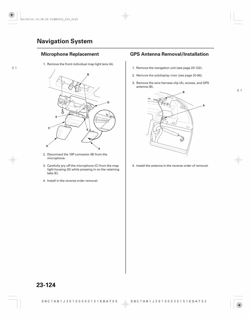
01
SNC7AN1J36100040151KBAT00
01
SNC7AN1J36100030151KDAT02
23-12423-124
Navigation System
Microphone Replacement GPS Antenna Removal/Installation
A
B
C
D
E
E
A
A
B
1. Remove the front individual map light lens (A).
2. Disconnect the 10P connector (B) from themicrophone.
3. Carefully pry off the microphone (C) from the maplight housing (D) while pressing in on the retainingtabs (E).
4. Install in the reverse order removal.
1. Remove the navigation unit (see page 23-122).
2. Remove the subdisplay visor (see page 20-86).
3. Remove the wire harness clip (A), screws, and GPSantenna (B).
4. Install the antenna in the reverse order of removal.
06/09/19 10:38:29 61SNC010_230_0125