Embed Size (px)
Citation preview


Wiring Schematics 101

Electrical Symbols
• Supplemental Inflatable Restraint (SIR) or Supplemental Restraint System (SRS) Icon
• This icon is used to alert the technician that the system contains SIR/SRS components that require certain precautions before servicing.
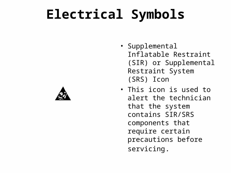
• Voltage Indicator Boxes
• These boxes are used on schematics to indicate when voltage is present at a fuse.
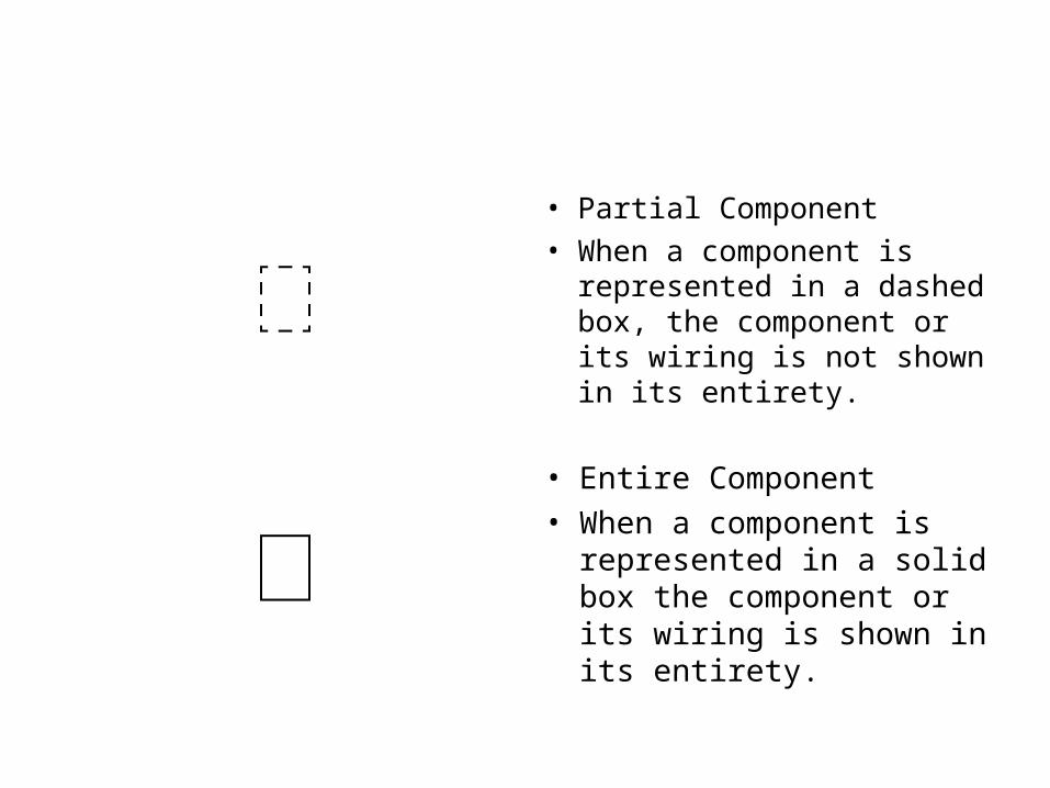
• Partial Component• When a component is
represented in a dashed box, the component or its wiring is not shown in its entirety.
• Entire Component
• When a component is represented in a solid box the component or its wiring is shown in its entirety.

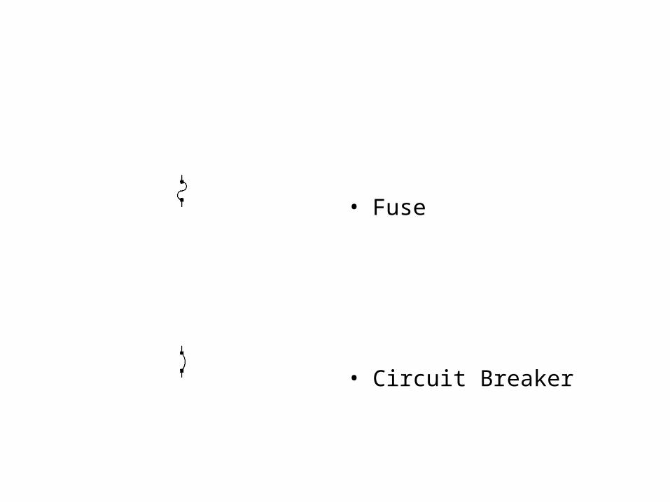
• Fuse
• Circuit Breaker
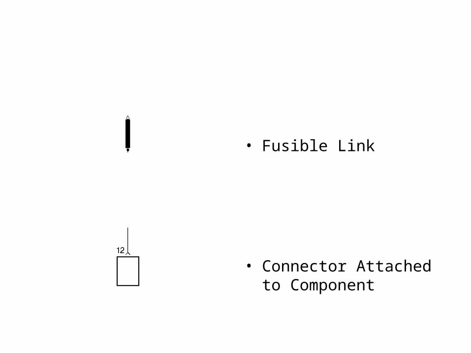
• Fusible Link
• Connector Attached to Component
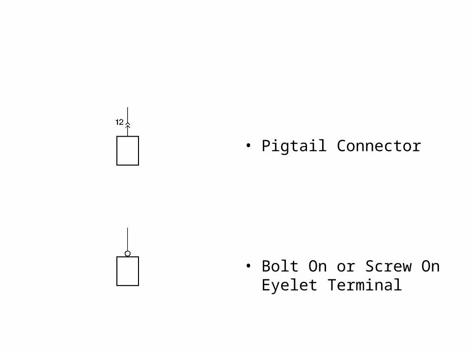
• Pigtail Connector
• Bolt On or Screw On Eyelet Terminal
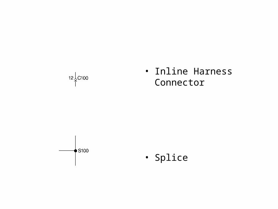
• Inline Harness Connector
• Splice
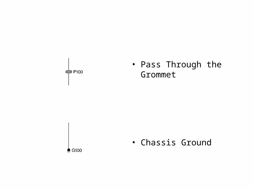
• Pass Through the Grommet
• Chassis Ground

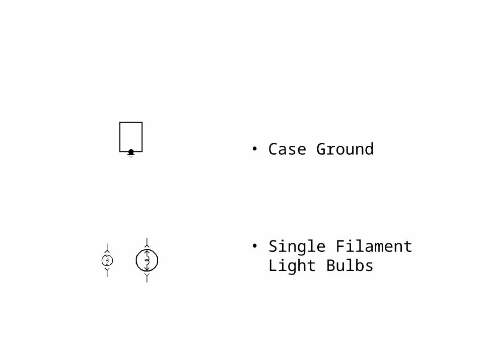
• Case Ground
• Single Filament Light Bulbs
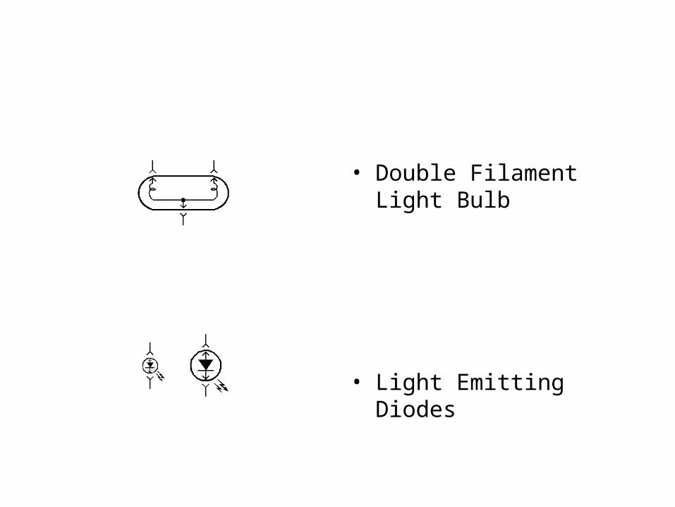
• Double Filament Light Bulb
• Light Emitting Diodes
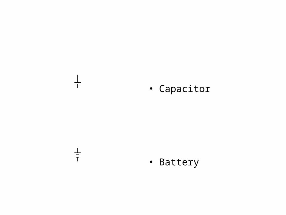
• Capacitor
• Battery
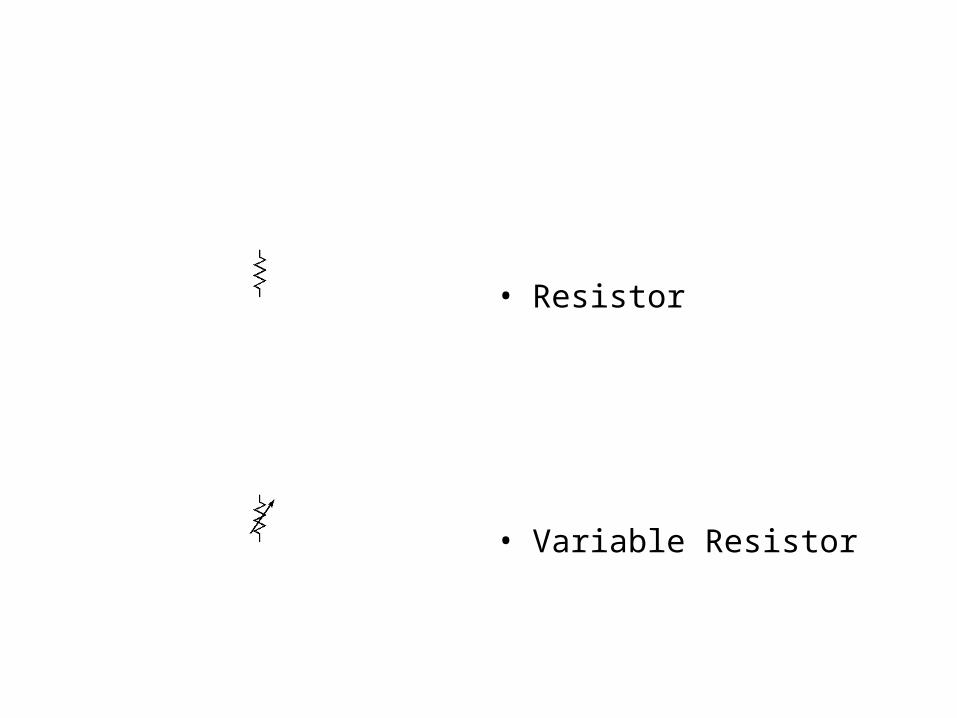
• Resistor
• Variable Resistor

• Position Sensor
• I/O Resistors
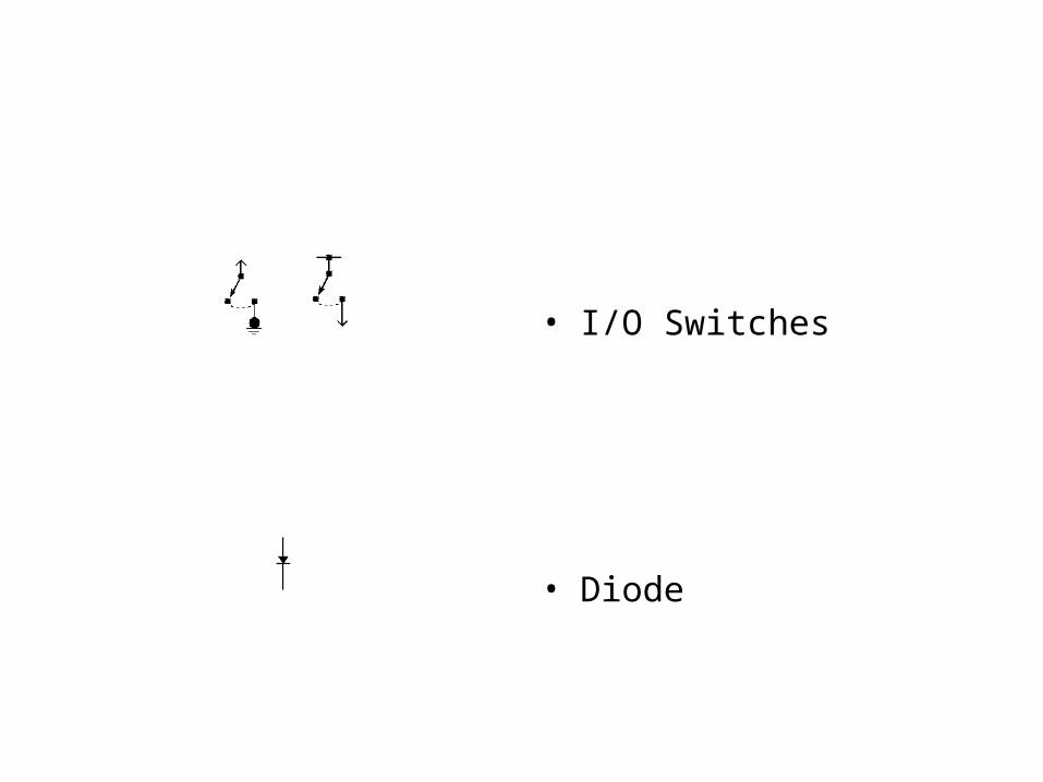
• I/O Switches
• Diode
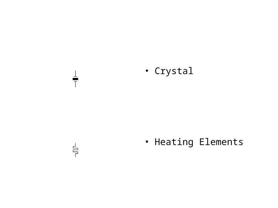
• Crystal
• Heating Elements
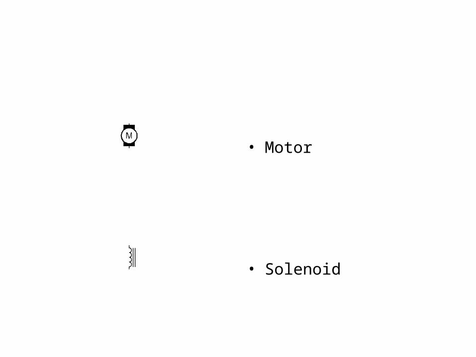
• Motor
• Solenoid
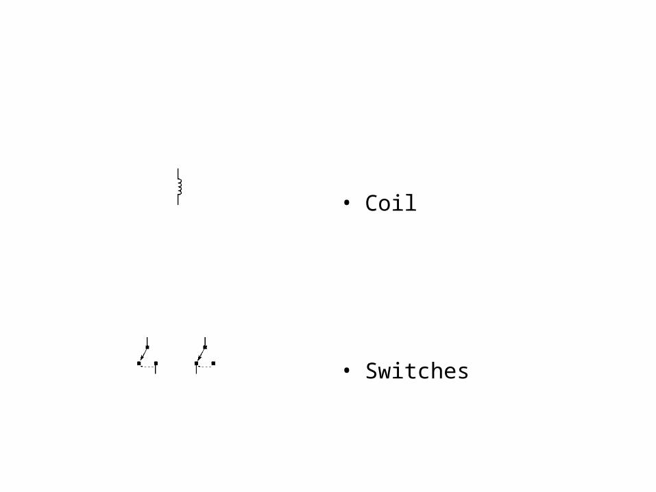
• Coil
• Switches
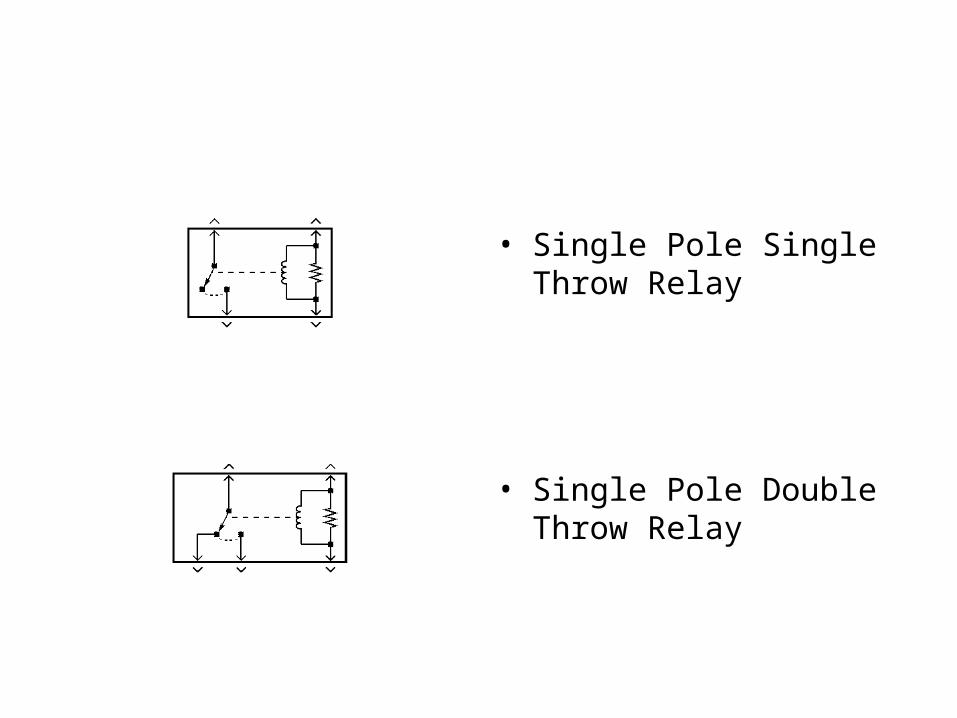
• Single Pole Single Throw Relay
• Single Pole Double Throw Relay
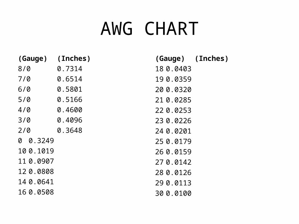
AWG CHART
(Gauge) (Inches)
8/0 0.7314
7/0 0.6514
6/0 0.5801
5/0 0.5166
4/0 0.4600
3/0 0.4096
2/0 0.3648
0 0.3249
10 0.1019
11 0.0907
12 0.0808
14 0.0641
16 0.0508
(Gauge) (Inches)
18 0.0403
19 0.0359
20 0.0320
21 0.0285
22 0.0253
23 0.0226
24 0.0201
25 0.0179
26 0.0159
27 0.0142
28 0.0126
29 0.0113
30 0.0100
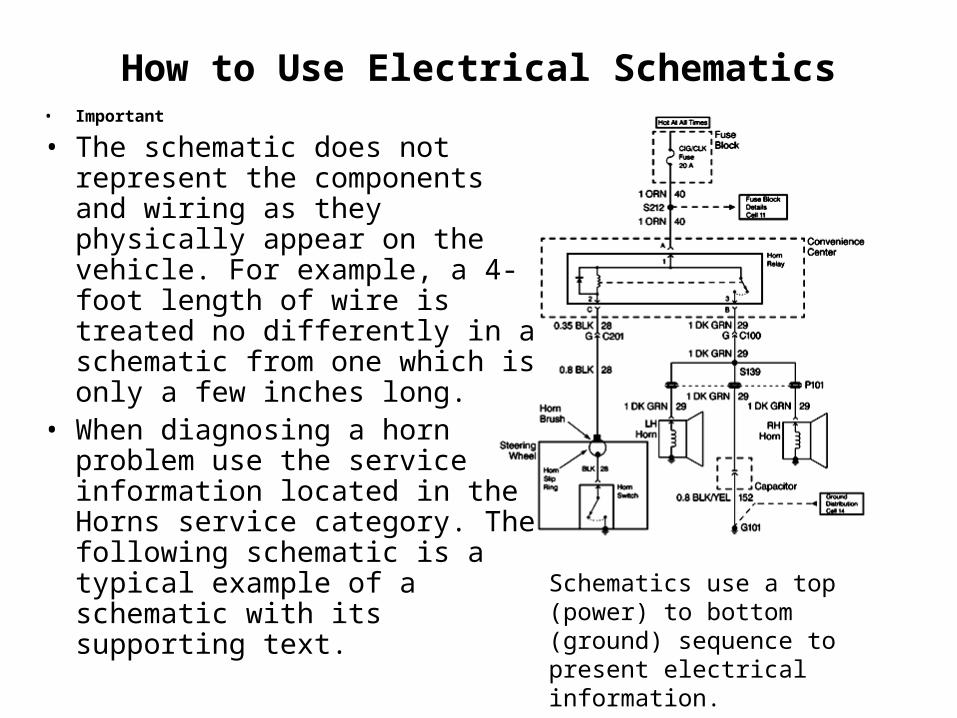
How to Use Electrical Schematics• Important
• The schematic does not represent the components and wiring as they physically appear on the vehicle. For example, a 4-foot length of wire is treated no differently in a schematic from one which is only a few inches long.
• When diagnosing a horn problem use the service information located in the Horns service category. The following schematic is a typical example of a schematic with its supporting text.
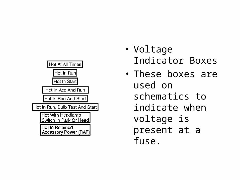
Schematics use a top (power) to bottom (ground) sequence to present electrical information.
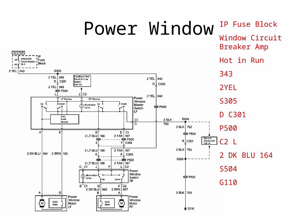
Power Window IP Fuse Block
Window Circuit Breaker Amp
Hot in Run
343
2YEL
S305
D C301
P500
C2 L
2 DK BLU 164
S504
G110
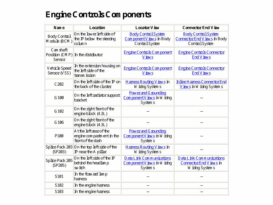
Engine Controls Components
Name Location Locator View Connector End View
Body Control Module (BCM)
On the lower left side of the IP below the steering column
Body Control System Component Views in Body
Control System
Body Control System Connector End Views in Body
Control System
Camshaft Position (CMP)
Sensor In the distributor
Engine Controls Component Views
Engine Controls Connector End Views
Vehicle Speed Sensor (VSS)
In the extension housing on the left side of the transmission
Engine Controls Component Views
Engine Controls Connector End Views
C202 On the left side of the IP on the back of the cluster
Harness Routing Views in Wiring Systems
Inline Harness Connector End Views in Wiring Systems
G100 On the left radiator support bracket
Power and Grounding Component Views in Wiring
Systems --
G102 On the right front of the engine block (4.3L)
-- --
G106 On the right front of the engine block (4.3L)
-- --
P100 At the left rear of the engine compartment in the front of the dash
Power and Grounding Component Views in Wiring
Systems --
Splice Pack 203 (SP203)
On the top left side of the IP near the A pillar
Harness Routing Views in Wiring Systems
--
Splice Pack 205 (SP205)
On the left side of the IP behind the headlamp switch
Data Link Communications Component Views in Wiring
Systems
Data Link Communications Connector End Views in
Wiring Systems
S101 In the forward lamp harness
-- --
S102 In the engine harness -- --
S103 In the engine harness -- --
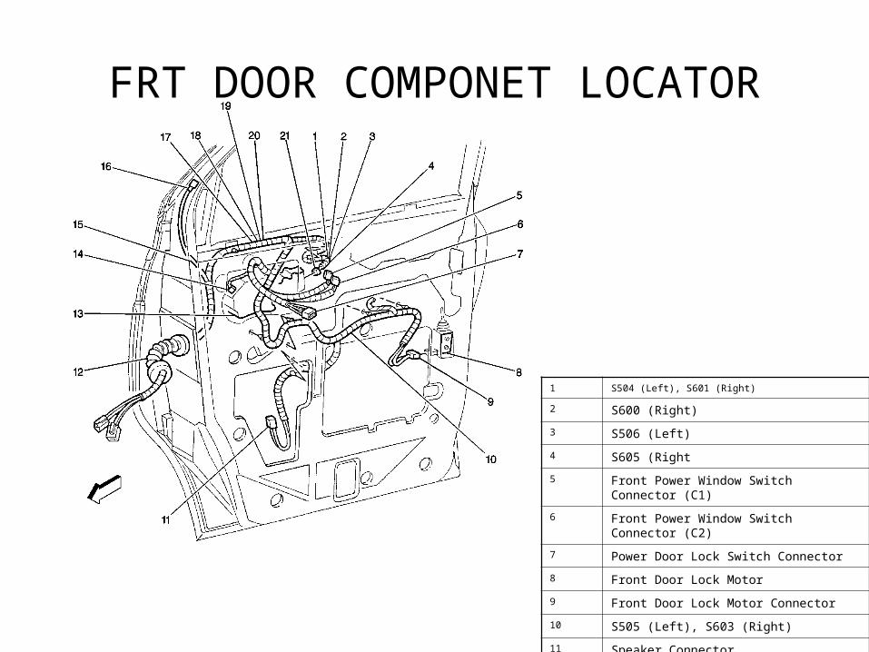
FRT DOOR COMPONET LOCATOR
1 S504 (Left), S601 (Right)
2 S600 (Right)
3 S506 (Left)
4 S605 (Right
5 Front Power Window Switch Connector (C1)
6 Front Power Window Switch Connector (C2)
7 Power Door Lock Switch Connector
8 Front Door Lock Motor
9 Front Door Lock Motor Connector
10 S505 (Left), S603 (Right)
11 Speaker Connector
12 P500 (Left), P600 (Right)
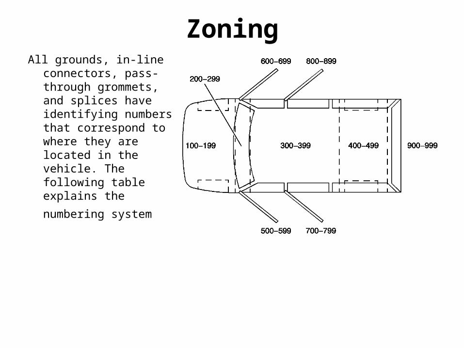
ZoningAll grounds, in-line
connectors, pass-through grommets, and splices have identifying numbers that correspond to where they are located in the vehicle. The following table explains the
numbering system
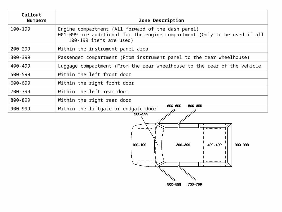
Callout Numbers Zone Description
100-199 Engine compartment (All forward of the dash panel)001-099 are additional for the engine compartment (Only to be used if all 100-199 items are used)
200-299 Within the instrument panel area
300-399 Passenger compartment (From instrument panel to the rear wheelhouse)
400-499 Luggage compartment (From the rear wheelhouse to the rear of the vehicle
500-599 Within the left front door
600-699 Within the right front door
700-799 Within the left rear door
800-899 Within the right rear door
900-999 Within the liftgate or endgate door
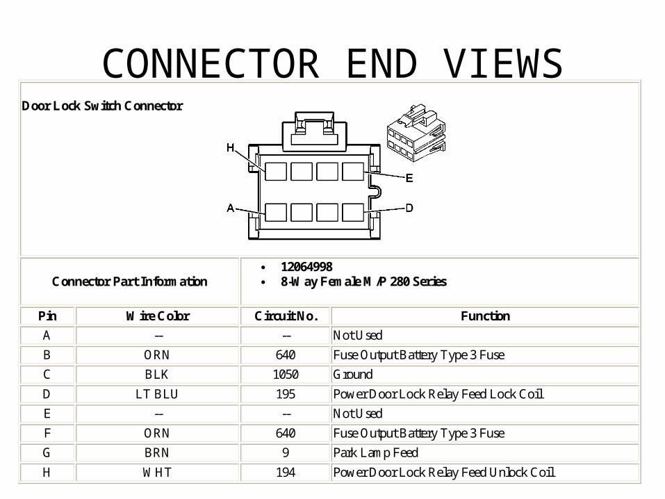
CONNECTOR END VIEWS
Door Lock Switch Connector
Connector Part Information 12064998 8-Way Female M/P 280 Series
Pin Wire Color Circuit No. Function
A -- -- Not Used
B ORN 640 Fuse Output Battery Type 3 Fuse
C BLK 1050 Ground
D LT BLU 195 Power Door Lock Relay Feed Lock Coil
E -- -- Not Used
F ORN 640 Fuse Output Battery Type 3 Fuse
G BRN 9 Park Lamp Feed
H WHT 194 Power Door Lock Relay Feed Unlock Coil
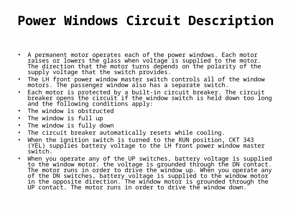
Power Windows Circuit Description
• A permanent motor operates each of the power windows. Each motor raises or lowers the glass when voltage is supplied to the motor. The direction that the motor turns depends on the polarity of the supply voltage that the switch provides.
• The LH front power window master switch controls all of the window motors. The passenger window also has a separate switch.
• Each motor is protected by a built-in circuit breaker. The circuit breaker opens the circuit if the window switch is held down too long and the following conditions apply:
• The window is obstructed • The window is full up • The window is fully down • The circuit breaker automatically resets while cooling.• When the ignition switch is turned to the RUN position, CKT 343 (YEL) supplies
battery voltage to the LH front power window master switch.• When you operate any of the UP switches, battery voltage is supplied to the window
motor. the voltage is grounded through the DN contact. The motor runs in order to drive the window up. When you operate any of the DN switches, battery voltage is supplied to the window motor in the opposite direction. The window motor is grounded through the UP contact. The motor runs in order to drive the window down.
TIME FOR EXTRA WORK