Embed Size (px)
Citation preview

State of Connecticut
Department of Transportation ___________________________________________________________
SUPPLEMENTAL SPECIFICATIONS
TO
STANDARD SPECIFICATIONS
FOR ROADS, BRIDGES, FACILITIES
AND INCIDENTAL CONSTRUCTION
FORM 818
2020
JULY 2021

CTDOT FORM 818 SUPPLEMENTAL SPECIFICATIONS Rev. July 2021
TABLE OF CONTENTS PAGE 1 OF 6
TABLE OF CONTENTS
As of July 2021 Supplements
Division I
GENERAL REQUIREMENTS AND COVENANTS
Section Rev Date Notes
1.01 Definition of Terms & Permissible Abbreviations ................. July 2021 Errata
1.02 Proposal Requirements and Conditions ..................................
1.03 Award and Execution of Contract ...........................................
1.04 Scope of Work ........................................................................
1.05 Control of the Work ................................................................ July 2021 & Errata
1.06 Control of Materials ................................................................
1.07 Legal Relations and Responsibilities ......................................
1.08 Prosecution and Progress ........................................................
1.09 Measurement and Payment ..................................................... July 2020 Errata
1.10 Environmental Compliance ....................................................
1.11 Claims .....................................................................................
1.20-1.00 General Clauses for Facilities Construction ...............
1.20-1.01 Definitions of Terms and Permissible Abbreviations .
for Facilities Construction ........................................... July 2021 Errata
1.20-1.02 Proposal Requirements and Conditions for Facilities .
Construction ................................................................
1.20-1.03 Award and Execution of Contract for Facilities
Construction ................................................................
1.20-1.04 Scope of Work for Facilities Construction .................
1.20-1.05 Control of the Work for Facilities Construction ......... July 2021 & Errata
1.20-1.06 Control of Materials for Facilities Construction .........
1.20-1.07 Legal Relations and Responsibilities for Facilities .....
Construction ................................................................
1.20-1.08 Prosecution and Progress for Facilities
Construction ................................................................
1.20-1.09 Measurement and Payment for Facilities
Construction ................................................................ July 2020 Errata
1.20-1.10 Environmental Compliance for Facilities
Construction ................................................................
1.20-1.11 Claims for Facilities Construction ..............................
1.20-9.75 Mobilization and Project Closeout for Facilities
Construction ................................................................
1.20-9.80 Construction Surveying for Facilities
Construction ............................................................... Jan 2021

CTDOT FORM 818 SUPPLEMENTAL SPECIFICATIONS Rev. July 2021
TABLE OF CONTENTS PAGE 2 OF 6
Division II
CONSTRUCTION DETAILS
EARTHWORK Section Rev. Date Notes
2.01 Clearing and Grubbing ............................................................
2.02 Roadway Excavation, Formation of Embankment
and Disposal of Surplus Material ............................................ July 2020 Errata
2.03 Structure Excavation ...............................................................
2.04 Cofferdam and Dewatering, Cofferdam Material Left
in Place ....................................................................................
2.06 Ditch Excavation ..................................................................... July 2020 Errata
2.07 Borrow ....................................................................................
2.08 Free-Draining Material ...........................................................
2.09 Subgrade .................................................................................
2.11 Anti-Tracking Pad ...................................................................
2.12 Subbase ...................................................................................
2.13 Granular Fill ............................................................................
2.14 Compacted Granular Fill.........................................................
2.16 Pervious Structure Backfill .....................................................
2.19 Sedimentation Control System ...............................................
2.86 Drainage Trench Excavation, Rock in Drainage Trench
Excavation............................................................................... July 2021
3.04 Processed Aggregate Base ......................................................
3.05 Processed Aggregate ...............................................................
SURFACE COURSES OR PAVEMENTS
4.01 Concrete for Pavement ............................................................
4.06 Bituminous Concrete .............................................................. Jan 2021
4.07 Rumble Strips, Removal of Rumble Strips ............................. Jan 2021
4.09 Milling, Removal of Wearing Surface .................................... July 2020
4.15 Pressure Relief Joint ...............................................................
STRUCTURES
5.03 Removal of Superstructure .....................................................
5.04 Railroad Protection .................................................................
5.06 Retaining Walls, Endwalls and Steps .....................................
5.08 Shear Connectors ....................................................................
5.09 Welded Studs ..........................................................................
5.13 Polyvinyl Chloride Plastic Pipe ..............................................
5.14 Prestressed Concrete Members ...............................................
5.21 Elastomeric Bearing Pads .......................................................

CTDOT FORM 818 SUPPLEMENTAL SPECIFICATIONS Rev. July 2021
TABLE OF CONTENTS PAGE 3 OF 6
Section ................................................................................................ Rev. Date Notes
5.22 Elastomeric Compression Seal ...............................................
5.86 Catch Basins, Manholes and Drop Inlets ................................ July 2021 Errata
6.01 Concrete for Structures ........................................................... July 2021 Errata
6.02 Reinforcing Steel .................................................................... July 2021
6.03 Structural Steel ........................................................................ Jan 2021 & Errata
6.05 Masonry Facing ......................................................................
6.06 Cement Rubble Masonry ........................................................
6.07 Dry Rubble Masonry...............................................................
6.09 Repointed Masonry .................................................................
6.11 Shotcrete .................................................................................
6.12 Concrete Cylinder Curing Box ...............................................
6.53 Clean Existing Drainage System ............................................
6.86 Drainage Pipes, Drainage Pipe Ends ...................................... July 2021
INCIDENTAL CONSTRUCTION
7.01 Drilled Shafts ..........................................................................
7.02 Piles .........................................................................................
7.03 Riprap ......................................................................................
7.04 Gabions ...................................................................................
7.05 Slope Paving ...........................................................................
7.06 Micropiles ...............................................................................
7.07 (Vacant) ................................................................................... July 2021
7.08 Dampproofing .........................................................................
7.13 Permanent Steel Sheet Piling ..................................................
7.14 Temporary Sheet Piling ..........................................................
7.15 Sheet Piling Material Left in Place .........................................
7.16 Temporary Earth Retaining System ........................................
7.17 Earth Retaining System Left in Place .....................................
7.28 Crushed Stone for Slope Protection ........................................
7.32 Concrete Block Slope Protection ............................................
7.51 Underdrain and Outlets ...........................................................
7.55 Geotextile ................................................................................
8.03 Paved Ditches, Paved Aprons and Paved Channels ................ July 2020
8.11 Concrete Curbing ....................................................................
8.13 Stone Curbing ......................................................................... July 2020 Errata
8.14 Reset Stone Curbing ...............................................................
8.15 Bituminous Concrete Lip Curbing ..........................................
8.18 Protective Compound for Bridges .......................................... July 2020 Deleted
8.21 Precast Concrete Barrier Curb ................................................
8.22 Temporary Precast Concrete Barrier ...................................... Jan 2021 Errata
9.04 Metal Bridge Rail ....................................................................
9.05 Stone Wall Fence ....................................................................

CTDOT FORM 818 SUPPLEMENTAL SPECIFICATIONS Rev. July 2021
TABLE OF CONTENTS PAGE 4 OF 6
Section ............................................................................................... Rev. Date Notes
9.06 Wire Fence ..............................................................................
9.10 Metal Beam Rail ..................................................................... July 2021 Errata
9.11 Metal Beam Rail Anchorages .................................................
9.12 Remove and Reset Posts, Rail
and Rail Anchorages ...............................................................
9.13 Chain Link Fence ....................................................................
9.14 Metal Handrail ........................................................................
9.15 Tree Root Protection ...............................................................
9.18 Three-Cable Guide Railing (I-Beam Posts)
and Anchorages .......................................................................
9.21 Concrete Sidewalks and Ramps .............................................. July 2021 & Errata
9.22 Bituminous Concrete Sidewalk, Bituminous
Concrete Driveway .................................................................
9.23 Bituminous Concrete for Patching ..........................................
9.24 Concrete Driveway Ramp ....................................................... July 2020
9.30 Object Marker .........................................................................
9.39 Sweeping for Dust Control .....................................................
9.42 Calcium Chloride for Dust Control ........................................
9.43 Water for Dust Control ...........................................................
9.44 Topsoil ....................................................................................
9.46 Liming .....................................................................................
9.49 Furnishing, Planting and Mulching Trees,
Shrubs, Vines and Ground Cover Plants.................................
9.50 Turf Establishment, Erosion Control Matting ........................
9.51 Rock Excavation for Planting .................................................
9.52 Selective Clearing and Thinning .............................................
9.53 Sodding ...................................................................................
9.70 Trafficperson ........................................................................... July 2020 Errata
9.71 Maintenance and Protection of Traffic ................................... July 2020
9.74 Removal of Existing Masonry ................................................
9.75 Mobilization and Project Closeout..........................................
9.76 Barricade Warning Lights ....................................................... July 2020 Errata
9.77 Traffic Cone ............................................................................ July 2020
9.78 Traffic Drum ........................................................................... July 2020
9.79 Construction Barricades .......................................................... July 2020
9.80 Construction Surveying ..........................................................
9.81 42 Inch Traffic Cone ............................................................... July 2020
9.99 Disposal of Buildings ..............................................................
TRAFFIC CONTROL
10.00 General Clauses for Highway Illumination
and Traffic Signal Projects ...................................................... Jan 2021 Errata
10.01 Trenching and Backfillling .....................................................
10.02 Light Standard and Traffic Control Foundations .................... Jan 2021 Errata

CTDOT FORM 818 SUPPLEMENTAL SPECIFICATIONS Rev. July 2021
TABLE OF CONTENTS PAGE 5 OF 6
Section ................................................................................................ Rev. Date Notes
10.03 Light Standards .......................................................................
10.04 Roadway Luminaire ................................................................
10.06 Underbridge Luminaire ...........................................................
10.08 Electrical Conduit ...................................................................
10.09 Cast Iron Junction Box............................................................
10.10 Concrete Handhole .................................................................. Jan 2021 Errata
10.11 4-Inch Drain Pipe ....................................................................
10.12 Single Conductor ....................................................................
10.14 Cable In Duct ..........................................................................
10.15 Grounding Conductor .............................................................
10.17 Service Entrance and Cabinet .................................................
10.18 Navigation Light ..................................................................... Jan 2021 Deleted
11.01 Pole Anchor ............................................................................
11.02 Pedestals ..................................................................................
11.03 Span Pole ................................................................................
11.05 Traffic Signals .........................................................................
11.06 Pedestrian Signal .....................................................................
11.07 Pedestrian Pushbutton ............................................................. Jan 2021 Errata
11.08 Controllers...............................................................................
11.11 Loop Vehicle Detector and Sawcut ........................................
11.12 Magnetic Vehicle Detector ..................................................... Jan 2021 Deleted
11.13 Control Cable ..........................................................................
11.14 Messenger and Span Wire ......................................................
11.16 Illuminated Signs .................................................................... July 2021 Errata
11.17 Alternate Flashing Signals for Warning Signs ........................
11.18 Removal and/or Relocation of Traffic Signal Equipment ......
11.30 Arrow Board ........................................................................... July 2020 Errata
11.31 Remote Control Changeable Message Sign ............................ July 2020 Errata
12.00 General Clauses for Highway Signing ....................................
12.01 Overhead Sign Support ...........................................................
12.02 Overhead Sign Support Foundation ........................................
12.03 Side Mounted Sign Foundation ..............................................
12.04 Sign Panel Overlay .................................................................
12.05 Delineators ..............................................................................
12.06 Removal of Existing Signing, Removal of Existing
Overhead Signing....................................................................
12.07 Sign Face - Extruded Aluminum ............................................
12.08 Sign Face - Sheet Aluminum ..................................................
12.09 Painted Pavement Markings ...................................................
12.10 Epoxy Resin Pavement Markings ........................................... July 2021 Errata
12.11 Removal of Pavement Markings .............................................
12.12 Temporary Plastic Pavement Marking Tape ........................... July 2020 Errata
12.14 Preformed Black Line Mask Pavement Marking Tape ...........

CTDOT FORM 818 SUPPLEMENTAL SPECIFICATIONS Rev. July 2021
TABLE OF CONTENTS PAGE 6 OF 6
Section ................................................................................................ Rev. Date Notes
12.20 Construction Signs .................................................................. July 2020 Errata
13.00 Utilities ....................................................................................
14.00 Vacant .....................................................................................
15.00 Vacant .....................................................................................
16.00 Vacant .....................................................................................
18.02 Sand Barrels ............................................................................
18.03 Impact Attenuation System, Temporary Impact
Attenuation System .................................................................
18.06 Truck-Mounted or Trailer-Mounted Impact Attenuator ......... July 2021 Errata
Division III
MATERIALS SECTION
M.01 Aggregates ..............................................................................
M.02 Granular Fill, Subbase, Granular Base and Surfaces,
Stone Base, Pervious Structure Backfill,
Free-Draining Material, Crusher-Run Stone ...........................
M.03 Portland Cement Concrete ...................................................... July 2021 & Errata
M.04 Bituminous Concrete Materials .............................................. July 2021 Errata
M.05 Processed Aggregate Base and Pavement
Surface Treatment ................................................................... Jan 2021
M.06 Metals ...................................................................................... July 2021 Errata
M.07 Paint ........................................................................................ July 2021 & Errata
M.08 Drainage .................................................................................. July 2021 Errata
M.09 Sheet Piling and Piles.............................................................. July 2021 Errata
M.10 Fence, Railing and Posts ......................................................... July 2021 Errata
M.11 Masonry Facing, Cement and Dry Rubble,
Masonry, Brick, Mortar ..........................................................
M.12 Bearing Areas, Riprap, Slope Paving & Slope Protection,
Waterproofing and Dampproofing, Stone and Granite
Slope Curbing, Calcium Chloride for Dust Control, Wood .... July 2021 Errata
M.13 Roadside Development ........................................................... July 2021 Errata
M.14 Prestressed Concrete Members ...............................................
M.15 Highway Illumination ............................................................. Jan 2021 & Errata
M.16 Traffic Control Signals ........................................................... Jan 2021 & Errata
M.17 Elastomeric Materials ............................................................. July 2021 Errata
M.18 Signing .................................................................................... July 2021 Errata
List of Standard Pay Items .................................................................. July 2021 Errata

CTDOT FORM 818 SUPPLEMENTAL SPECIFICATIONS - ERRATA 1st Rev. July 2020
2nd Rev. January 2021
3rd Rev. July 2021
ERRATA TO FORM 818 PAGE 1 OF 5 ERRATA TO FORM 818
Section
or
Article
Please make the following Corrections: Rev.
Date
Division I GENERAL REQUIREMENTS AND COVENANTS
1.01.02
1. after the abbreviation for ADSC add “AFBMA—Anti-Friction Bearing
Manufacturer’s Association”
2. after the abbreviation for AGC add “AGMA—American Gear Manufacturer’s
Association”
3. after the abbreviation for AMRL add “AMS—Aerospace Material Specification”
4. after the abbreviation for AWWA add “BGFMA—Bridge Grid Flooring
Manufacturer’s Association”
July20
1.01.02
1. after the abbreviation for AMCA add “AMPP—The Association for Materials
Protection and Performance [formerly NACE and SSPC]”
2. after the abbreviation for EPA add “ETL—Edison Testing Laboratories”
3. after the abbreviation for IAS add “IBC—International Building Code”
4. revise the abbreviation for NACE to “NACE — National Association of Corrosion
Engineers see AMPP”
5. after the abbreviation for NTMA add “NTPEP —National Transportation Product
Evaluation ”
6. after the abbreviation for RCSA add “RCSC—Research Council on Structural
Connections”
7. revise the abbreviation for SSPC to “SSPC —The Society for Protective Coatings
(formerly The Steel Structures Painting Council) see AMPP” but keep the NOTE
Jan21
1.01.02
1. after the abbreviation for ACI add “ACMA—American Composites Manufacturers’
Association”
2. After the abbreviation for NOAA add “NPCA—National Precast Concrete
Association” 3. after the abbreviation for TIA/EIA add “TMS—the Masonry Society”
4. change the entry for USACOE to “USACE—United States Army Corps of
Engineers”
July21
1.01.03
1. after the abbreviation for pfmd. add “PQR—procedure qualification record”
2. after the abbreviation for surf. add “TBD—to be determined”
3. after the abbreviation for W add “WPS—weld procedure specification”
July20
1.01.03 after the abbreviation for CMS add “CMU—concrete masonry unit” July21
1.05.12 in the first sentence of the paragraph that begins “Each such payroll shall include...”
replace “... and, if applicable, …" with “... or …" July20
1.09.02
1. change the first sentence to “These Value Engineering Change Proposal (VECP)
provisions apply as encouragement to the Contractor to initiate, develop, and present
to the Department for consideration cost-reduction proposals conceived by the
Contractor, involving changes to the drawings, designs, specifications or other
requirements of the Contract.”
2. under the Subarticle “Payment for accepted VECPs,” delete “5. The cost savings
from a VECP that is exclusively time reduction shall be calculated as the number of
Contract days reduced multiplied by the amount of liquidated damages for 1 day
under the Contract.”
(VECPs based on time savings only will not be accepted)
July20

CTDOT FORM 818 SUPPLEMENTAL SPECIFICATIONS - ERRATA 1st Rev. July 2020
2nd Rev. January 2021
3rd Rev. July 2021
ERRATA TO FORM 818 PAGE 2 OF 5 ERRATA TO FORM 818
Division I GENERAL REQUIREMENTS AND COVENANTS, GENERAL CLAUSES FOR
FACILITIES CONSTRUCTION
1.20-1.01.02
1. after the abbreviation for ADSC add “AFBMA—Anti-Friction Bearing
Manufacturer’s Association”
2. after the abbreviation for AGC add “AGMA—American Gear
Manufacturer’s Association”
3. after the abbreviation for AMRL add “AMS—Aerospace Material
Specification”
4. after the abbreviation for AWWA add “BGFMA—Bridge Grid Flooring
Manufacturer’s Association”
July20
1.20-1.01.02
1. after the abbreviation for AMCA add “AMPP—The Association for
Materials Protection and Performance [formerly NACE and SSPC]” 2. after the abbreviation for EPA add “ETL—Edison Testing Laboratories”
3. after the abbreviation for IAS add “IBC—International Building Code”
4. revise the abbreviation for NACE to “NACE — National Association of
Corrosion Engineers see AMPP”
5. after the abbreviation for NTMA add “NTPEP —National Transportation
Product Evaluation ”
6. after the abbreviation for RCSA add “RCSC—Research Council on
Structural Connections”
7. revise the abbreviation for SSPC to “SSPC —The Society for Protective
Coatings (formerly The Steel Structures Painting Council) see AMPP” but
keep the NOTE
Jan21
1.20-1.01.02
1. after the abbreviation for ACI add “ACMA—American Composites
Manufacturers’ Association” 2. After the abbreviation for NOAA add “NPCA—National Precast Concrete
Association” 3. after the abbreviation for TIA/EIA add “TMS—the Masonry Society”
4. change the entry for USACOE to “USACE—United States Army Corps of
Engineers”
July21
1.20-1.01.03
1. after the abbreviation for pfmd. add “PQR—procedure qualification record”
2. after the abbreviation for surf. add “TBD—to be determined”
3. after the abbreviation for W add “WPS—weld procedure specification”
July20
1.20-1.01.03 after the abbreviation for CMS add “CMU—concrete masonry unit” July21
1.20-1.05.12 in the first sentence of the paragraph that begins “Each such payroll shall
include...” replace “... and, if applicable, …" with “... or …" July20
1.20-1.05.19
change “1.20-1.05.19—Facilities Construction - Field Erector
Prequalification” to “1.20-1.05.19—Facilities Construction - Field Erector
Certification”
Jan21
1.20-1.09.02
1. change the first sentence to “These Value Engineering Change Proposal
(VECP) provisions apply as encouragement to the Contractor to initiate,
develop, and present to the Department for consideration cost-reduction
proposals conceived by the Contractor, involving changes to the drawings,
designs, specifications or other requirements of the Contract.”
2. under the Subarticle “Payment for accepted VECPs,” delete “5. The cost
savings from a VECP that is exclusively time reduction shall be calculated as
the number of Contract days reduced multiplied by the amount of liquidated
damages for 1 day under the Contract.”
(VECPs based on time savings only will not be accepted)
July20

CTDOT FORM 818 SUPPLEMENTAL SPECIFICATIONS - ERRATA 1st Rev. July 2020
2nd Rev. January 2021
3rd Rev. July 2021
ERRATA TO FORM 818 PAGE 3 OF 5 ERRATA TO FORM 818
Division II CONSTRUCTION DETAILS
2.02.03 in the third paragraph of subarticle 5. Placement of Embankment Material
replace “... slopes steeper than 1:3 ...” with “... slopes 1 vertical to 3 horizontal
or steeper ...”
July20
2.06.01 change the first sentence of the only paragraph as follows “...necessary for the
construction of drainage ditches and paved leak-offs...” July20
2.06.04 change subarticle 2. Paved Leak-offs and Paved Ditches to “2. Paved Leak-
offs" July20
6.01.03
1. in the eighth paragraph of subarticle 6.01.03-II-1(g) Stay-In-Place Metal
Forms for Bridge Decks, replace “FS No. TT-P-641d, Type II” with “MIL-
DTL-24441"
2. in the eleventh paragraph of subarticle 6.01.03-II-1(g) Stay-In-Place Metal
Forms for Bridge Decks, replace “the Welding subarticle in 6.03” with
“1.05.17, Welding.”
3. in the fourth sentence of subarticle 6.01.03-II-10(b) Rubbed Finish, replace
“stripping” with “striping”
July20
6.01.03
in the last paragraph of subarticle 6.01.03-II-5 Progression Cylinders and
Compressive Strength Specimens, change the first sentence as follows “A
Certified Test Report in accordance with 1.06.07 or 1.20-1.06.07 shall be...”
July21
6.01.05 in Table 6.01.05-2b Permeability Pay Factors, change the heading to read
“Permeability Pay Factors (PCCXXXX2 mix classifications only)” Jan21
6.03.03
in the second paragraph of subarticle 6.03.03-4(e) Inspection, change the third
sentence as follows “A Materials Certificate in accordance with 1.06.07 or
1.20-1.06.07 may be used...”
July21
8.13.04 change the only sentence as follows “… will be measured for payment along the
top arris line of the curb ...” July20
8.22.02
change the first sentence as follows “The materials for this work shall meet the
requirements of 8.21.02, except the reinforcing steel does not need to be
galvanized.”
Jan21
9.10.02 Change subarticle 1. "Chemical anchoring material …" as follows "Adhesive
anchoring material …" July21
9.10.05
change the second sentence of subarticle 9.10.05-3 (Type) Attachment as
follows “The price shall include all materials, drilling and bonding including
anchor bolts …”
July21
9.21.03 in the last sentence of 6. Curing change “6.01.03-9” to “6.01.03-II-9” July20
9.70.03 in the first sentence of paragraph 5, insert “the” before “MUTCD” July20
9.76.03 change the last paragraph to “… in accordance with the ATSSA “Quality
Guidelines for Temporary Traffic Control Devices and Features,” shall be …” July20
10.00.10 in the first sentence of the second paragraph under 10.00.10-2(b)-1, change
“push button” to “pushbutton” Jan21
10.02.02 in the second line of the list, change “PCC03340” to “PCC04461” Jan21
10.02.05 in the first sentence, change “PCC03340” to “PCC04461” Jan21
10.10.02 in the third line of the list, change “PCC03360” to “PCC04461” Jan21
11.07 change “push button” to “pushbutton” everywhere it appears Jan21
11.16.02 in the only sentence, change “M.16.18” to “M.16.17” July21
11.30.02 in the first paragraph, insert “the” before “MUTCD” July20
11.30.03 change the second paragraph to “… in accordance with the ATSSA “Quality
Guidelines for Temporary Traffic Control Devices and Features.” July20
11.31.02 in the first paragraph, insert “the” before “MUTCD” July20

CTDOT FORM 818 SUPPLEMENTAL SPECIFICATIONS - ERRATA 1st Rev. July 2020
2nd Rev. January 2021
3rd Rev. July 2021
ERRATA TO FORM 818 PAGE 4 OF 5 ERRATA TO FORM 818
12.10.03
in the first paragraph of subarticle 12.10.03-3 Initial Performance, change the
second sentence as follows “A Certified Test Report (CTR), in accordance with
1.06.07 or 1.20-1.06.07, must be submitted...”
July21
12.12.05
change the second to last paragraph to “… in accordance with the ATSSA
“Quality Guidelines for Temporary Traffic Control Devices and Features,” shall
be …”
July20
12.20.03
change the second to last paragraph to “… in accordance with the ATSSA
“Quality Guidelines for Temporary Traffic Control Devices and Features,” shall
be …”
July20
18.06.02 change the first sentence of Article 18.06.02 as follows “... a Materials
Certificate in accordance with 1.06.07 or 1.20-1.06.07 for each...” July21
Division III MATERIALS SECTION
M.04.01
in the only paragraph of subarticle M.04.01-8 Joint Seal Material, change the
second sentence as follows “... a Materials Certificate in accordance with
1.06.07 or 1.20-1.06.07 certifying that...”
July21
M.06.01
in the second paragraph of subarticle M.06.01-8 Reports and Certification,
change the only sentence as follows “Materials Certificates shall be submitted
in accordance with 1.06.07 or 1.20-1.06.07 for all...”
July21
M.06.02
1. change the first sentence of Article M.06.02 as follows “... shall be
submitted in accordance with 1.06.07 or 1.20-1.06.07.” 2. change the first sentence of subarticle M.06.02-2(b) Anchor Bolts as follows
“... Certified Test Reports in accordance with 1.06.07 or 1.20-1.06.07.” 3. change the first sentence of subarticle M.06.02-3(f) Certified Test Reports
and Materials Certificates as follows “... Certified Test Reports and
Materials Certificates in accordance with 1.06.07 or 1.20-1.06.07...” 4. in subarticle M.06.02-4(d) Certified Test Reports and Materials
Certificates change the first sentence as follows “... quality control test
report in conformance with 1.06.07 or 1.20-1.06.07.” and change the second
sentence as follows “... Materials Certificate in conformance with 1.06.07 or
1.20-1.06.07 ...”
July21
M.08.01 change the only sentence in the first paragraph as follows “... metal coupling
bands in accordance with 1.06.07 or 1.20-1.06.07.” July21
M.09.02
change the last sentence of subarticle M.09.02-2 Treatment of Timber Piles
as follows “... Materials Certificate, in accordance with 1.06.07 or 1.20-1.06.07,
certifying...” July21
M.10.02
change the last sentence of subarticle M.10.02-9 Plastic Blockouts as follows
“... Materials Certificate for blockouts in conformance with 1.06.07 or 1.20-
1.06.07.” July21
M.10.05
in the second paragraph of subarticle M.10.05-2 Metal Posts and Rails,
change the first sentence as follows “... Materials Certificate in accordance with
1.06.07 or 1.20-1.06.07 for all...” July21
M.12.13 change the only sentence in the second paragraph as follows “... Materials
Certificate in accordance with 1.06.07 or 1.20-1.06.07.” July21
M.13.06
change the last sentence in the first paragraph as follows “... Materials
Certificate and Certified Test Report in accordance with Section 1.06.07 or
1.20-1.06.07.” July21
M.13.07 change subarticle “14. Miscellaneous” as follows “11. Miscellaneous” July21
M.15.15-5 in the first sentence, change “PCC03340” to “PCC04461” Jan21
M.15.15-6 in the first sentence, change “PCC03340” to “PCC04461” Jan21
M.16.08 change “push button” to “pushbutton” everywhere it appears Jan21

CTDOT FORM 818 SUPPLEMENTAL SPECIFICATIONS - ERRATA 1st Rev. July 2020
2nd Rev. January 2021
3rd Rev. July 2021
ERRATA TO FORM 818 PAGE 5 OF 5 ERRATA TO FORM 818
M.17.01
1. change the last sentence of subarticle M.17.01-3(c) as follows “... for each
lot in accordance with the requirements of 1.06.07 or 1.20-1.06.07.” 2. change the first sentence of subarticle M.17.01-4(c) as follows “... for each
batch in accordance with the requirements of 1.06.07 or 1.20-1.06.07.”
July21
M.17.02
1. change the last sentence of the second paragraph as follows “... for each lot
in accordance with the requirements of 1.06.07 or 1.20-1.06.07.” 2. change the last sentence in the last paragraph as follows “... for each batch
in accordance with the requirements of 1.06.07 or 1.20-1.06.07.”
July21
M.18.10
change the only sentence of subarticle M.18.10-3(M) Quality Assurance as
follows “... Certified Test Report in accordance with 1.06.07 or 1.20-1.06.07
shall be submitted.” July21
LIST OF STANDARD PAY ITEMS, ENGLISH/METRIC CONVERSION CHARTS, INDEX
N/A
1. delete “4.09, Micro-Milling of Bituminous Concrete (0” to 3”), s.y.”
2. change “4.09, Standard Milling of Bituminous Concrete (Greater Than 4” up
to 8”), s.y.” to “4.09, Coarse Milling of Bituminous Concrete (Greater Than
4” Up To 8”), s.y.”
3. change “4.09, Standard Milling of Bituminous Concrete (Greater Than 8”),
s.y.” to “4.09, Coarse Milling of Bituminous Concrete (Greater Than 8”),
s.y.”
4. delete “8.03, Paved Ditch, s.y.”
5. delete “8.03, Paved Channel, s.y.”
6. delete “8.18, Protective Compound for Bridges, s.y.”
July20
N/A
1. add “4.07, Rumble Strips – Automated, l.f.” 2. add “4.07, Rumble Strips – Manual, l.f.” 3. add “4.07, Removal of Rumble Strips, l.f.” 4. delete “10.18, Navigation Light, ea.” 5. change “11.07, Pedestrian Push Button and Sign (Type), ea.” to “11.07,
Pedestrian Pushbutton and Sign (Type), ea.” 6. delete “11.12, Magnetic Vehicle Detector (Type), ea.”
Jan21
N/A
1. delete “7.07, Membrane Waterproofing (Woven Glass Fabric)”
2. change “9.21, Detectable Warning Strip, ea.” to “9.21, Detectable Warning
Surface, s.f.”
July21

CTDOT FORM 818 SUPPLEMENTAL SPECIFICATION 1st Rev. January 2021
2nd Rev. July 2021
CONTROL OF THE WORK 1.05 – PAGE 1 OF 1
SECTION 1.05
CONTROL OF THE WORK
In the list of Articles, add the following:
1.05.19—Field Erector Certification
Replace Article 1.05.12 with the following:
1.05.12—Payrolls: For each week of the Project from the first week during which an employee of the Contractor
does Project work to which prevailing wage requirements apply, until the last week on which such an employee does
such work, the Contractor shall furnish to the Engineer certified copies of payrolls showing
(a) the names of the employees who worked on the Project and whose work is subject to prevailing wage
requirements,
(b) the specific days and hours and numbers of hours that each such employee worked on the Project, and
(c) the amount of money paid to each such employee for Project work.
Each such payroll shall include the statement(s) of compliance with prevailing wage laws required by the State of
Connecticut or by the Federal government. Said payrolls must contain all information required by CGS 31-53 (as it
may be revised). For contracts subject to Federal prevailing wage requirements, each payroll shall also contain the
information required by the Davis Bacon and Related Acts (DBR). All of the payroll requirements in this Article
shall also apply to the work of any subcontractor or other party that performs work on the Project site, and the
Contractor shall be responsible for ensuring that each such party meets said requirements. No Social Security
Numbers (in whole or in part) shall appear on any certified payrolls.
Every Contractor or subcontractor performing Project work is required to post the relevant prevailing wage rates as
determined by the State Labor Commissioner and, on federal aid projects, those determined by the United States
Secretary of Labor. The wage rate determinations shall be posted in prominent and easily accessible places at the
work site.
After 1.05.18, add the following:
1.05.19—Field Erector Certification: Contractors and subcontractors are required to possess AISC Certified
Steel Erector (CSE) Certification with a Bridge Erection Endorsement for the following work:
1. Field erection of steel bridge girders, beams or trusses.
2. Field erection of fabricated steel sign supports (overhead and cantilever).
Contractors and subcontractors are required to possess an AISC Certified Steel Erector (CSE) Certification for
Steel-Framed Buildings for the field erection of steel frames on Facilities Construction projects.

CTDOT FORM 818 SUPPLEMENTAL SPECIFICATION Rev. July 2021
CONTROL OF THE WORK
FOR FACILITIES CONSTRUCTION 1.20-1.05 – PAGE 1 OF 1
SECTION 1.20-1.05
CONTROL OF THE WORK FOR
FACILITIES CONSTRUCTION
Replace Article 1.20-1.05.12 with the following:
1.20-1.05.12—Facilities Construction - Payrolls: For each week of the Project from the first week
during which an employee of the Contractor does Project work to which prevailing wage requirements
apply, until the last week on which such an employee does such work, the Contractor shall furnish to the
Engineer certified copies of payrolls showing the names of the employees who worked on the Project and
whose work is subject to prevailing wage requirements,
(a) the specific days and hours and numbers of hours that each such employee worked on the Project,
and
(b) the amount of money paid to each such employee for Project work.
Each such payroll shall include the statement(s) of compliance with prevailing wage laws required by the
State of Connecticut or by the Federal government. Said payrolls must contain all information required by
CGS Section 31-53 (as it may be revised). For contracts subject to Federal prevailing wage requirements,
each payroll shall also contain the information required by the Davis Bacon and Related Acts (DBR). All
of the payroll requirements in this Article shall also apply to the work of any subcontractor or other party
that performs work on the Project site, and the Contractor shall be responsible for ensuring that each such
party meets said requirements. No Social Security Numbers (in whole or in part) shall appear on any
certified payrolls. Every Contractor or subcontractor performing Project work is required to post the relevant prevailing
wage rates as determined by the State Labor Commissioner and, on federal aid projects, those determined
by the United States Secretary of Labor. The wage rate determinations shall be posted in prominent and
easily accessible places at the work site.

CTDOT FORM 818 SUPPLEMENTAL SPECIFICATION Rev. January 2021
CONSTRUCTION SUREYING FOR
FACILITIES CONSTRUCTION 1.20-9.80 – PAGE 1 OF 5
After Section 1.20-9.75, add the following New Section 1.20-9.80:
SECTION 1.20-9.80
CONSTRUCTION SURVEYING FOR
FACILITIES CONSTRUCTION
1.20-9.80.01—Facilities Construction - Description
1.20-9.80.02—Facilities Construction - Materials
1.20-9.80.03—Facilities Construction - Construction Methods
1.20-9.80.04—Facilities Construction - Method of Measurement
1.20-9.80.05—Facilities Construction - Basis of Payment
1.20-9.80.01—Facilities Construction - Description: Work under this item shall consist of furnishing
labor, equipment, tools and materials to perform surveying, staking, verification, recording of data and
calculations as necessary to construct the Project, from existing layout to acceptance of the work according
to the plans. Work under this item shall conform to Section 20-300b-1 to 20-300b-20 inclusive of the
Department of Consumer Protection, Regulations of CT State Agencies and as supplemented herein.
1.20-9.80.02—Facilities Construction - Materials: Stakes used for control staking shall be a minimum
of 1 inch × 1 inch wide and a minimum length of 36 inches. Stakes shall be legibly marked and shall be
visible at all times. The stakes shall be durable enough to last for the duration of the Contract. In areas
where traditional staking cannot be established, the Contractor may use other materials or methods to mark
critical locations, as approved or directed by the Engineer.
1.20-9.80.03—Facilities Construction - Construction Methods:
I Submittals:
1. The Contractor shall provide technically qualified survey crews experienced in construction surveying.
All Project surveying and staking shall be performed by or under the supervision of either a
Connecticut Licensed Land Surveyor or a Level III Survey Technician certified by the National
Society of Professional Surveyors.
The name, authority, relevant experience, and qualifications of the person with overall responsibility
for construction surveying and staking shall be submitted to the Engineer ten (10) days prior to any
physical work.
The Contractor shall submit Project Record Drawings as required under 1.20-1.08.14. Project
Record Drawings shall be the appropriate scale, reproducible final drawings meeting the accuracy
requirements of an “Improvement Location Survey,” Class A-2.
2. If using Automated Machine Guidance (AMG) methods, the following information shall also be
submitted to the Engineer ten (10) days prior to any physical work:
A. A written technology statement that includes:
i. The manufacturer, model, and software version of the AMG equipment.
ii. Verification that the final 3D data which is provided in the Plans is compatible with the
AMG equipment.
B. Personnel qualifications:
i. The name, authority, relevant experience, and qualifications of the person with overall
responsibility for the AMG system.
ii. The name, authority, and relevant experience of personnel directly responsible for operating
the AMG equipment.
C. A Quality Control Plan for mechanical calibration and maintenance of both surveying and AMG
controlled construction equipment. Include the frequency and types of checks performed.
II Equipment Requirements:
1. The Contractor’s survey instruments and supporting equipment shall be capable of achieving the
specified tolerances in Table 1.20-9.80-1.
2. All instrumentation used on the Project shall have been serviced and calibrated within six (6) months
prior to use on the Project, and then every year thereafter.
3. The Contractor shall obtain the Engineer’s concurrence prior to using construction equipment equipped
with Global Navigation Satellite System (GNSS) or Robotic Total Station (RTS) controlled by an
AMG system in the construction of subgrade, subbase and base course aggregate courses, or other
construction operations.
4. Tools and supplies shall be of the type and quality suitable for survey work.
5. Stakes and hubs shall be of a sufficient length to provide a solid set in the ground, with sufficient

CTDOT FORM 818 SUPPLEMENTAL SPECIFICATION Rev. January 2021
CONSTRUCTION SUREYING FOR
FACILITIES CONSTRUCTION 1.20-9.80 – PAGE 2 OF 5
surface area above ground for necessary legible and durable markings.
III General Requirements:
1. The Contractor’s Construction Schedule shall include dates and sequences of major surveying
activities in accordance with 1.20-1.05.08 for Facilities Construction.
2. The Department will furnish the initial horizontal control points, vertical control points and data for
use in establishing control for completion of the work. The Contractor shall recover and preserve the
initial reference and control points and shall notify the Engineer of missing control points.
3. The Department will furnish data relating to horizontal and vertical alignments, theoretical slope
staking catch points, and other design data. The Contractor is responsible for reformatting and any
additional calculations that may be required for the convenient use of the State-furnished data. The
Contractor shall provide immediate notification of apparent errors or omissions in the initial staking or
in the State-furnished data.
4. The Contractor shall provide survey data and measurements in the format(s) acceptable to the Engineer
and submit on a schedule determined by the Engineer. Field data and supporting documentation will
become the property of the Department upon completion of the work.
5. Prior to major surveying activities, a survey coordination meeting shall be held, and the following
agenda items shall be discussed and coordinated with the Engineer:
A. Surveying and staking methods;
B. Stake marking;
C. Grade control for courses of material;
D. Referencing;
E. Structure control;
F. Field staking data;
G. Localization of the GNSS systems to the Department-established control points;
H. Protection of existing survey markers; and
I. Other procedures and controls necessary for the work.
6. The Contractor shall not start the physical work until the required survey or three-dimensional (3D)
verification data for the affected work has been reviewed by the Engineer. Review of the construction
survey does not relieve the Contractor of responsibility for correcting errors and omissions discovered
during the work and for bearing additional costs associated with the error or omission.
7. The Contractor shall maintain legibility of survey markings for the duration of the Project or until
notified by the Engineer.
8. Upon completion of the Project, the Contractor shall remove and dispose of all staking material used
on the Project.
9. Should the establishment or re-establishment of property acquisition lines, highway lines, or
non-access lines be required, the Contractor shall notify the Engineer at least two (2) weeks in advance
of need.
10. The Contractor shall provide and maintain safe facilities for convenient access by Department forces to
all survey stakes, control points, batter boards, and references.
IV Specific Requirements:
1. Control points: The Contractor shall
A. Relocate initial horizontal and vertical control points in conflict with construction to areas that will
not be disturbed by construction operations.
B. Furnish the coordinates, elevations, and support documentation for the relocated points before the
initial points are disturbed.
C. Set durable markers for survey control that uniquely identifies the points.
D. Furnish the GNSS localization results at least seven (7) days before beginning construction layout
survey work. If necessary, the GNSS localization calibration and associated 3D model shall be
broken into two or more zones to maintain the localized relationship between control points and
original ground.
2. Centerline establishment: The Contractor shall establish or reestablish centerline at roadway design
cross-section locations as necessary to construct the work.
3. Original ground topographic verification: In areas where the plan existing ground elevation and the
actual ground elevation are not within a tolerance of ±0.25 feet, the Contractor shall immediately
notify the Engineer.
4. Horizontal Slope Limits and Reference Stakes: The Contractor shall

CTDOT FORM 818 SUPPLEMENTAL SPECIFICATION Rev. January 2021
CONSTRUCTION SUREYING FOR
FACILITIES CONSTRUCTION 1.20-9.80 – PAGE 3 OF 5
A. At a minimum, set stakes on both sides of centerline at the horizontal slope limit at cross-section
intervals.
B. When the slope is designed with a roll at the top and toe, two stakes shall be set on each side of the
roadway, one to mark the intersection of the normal cut or fill with existing ground and the other
to determine the limit of the roll.
5. Clearing and Grubbing Limits: The Contractor shall set clearing and grubbing limits on both sides
of centerline.
6. Finish-grade stakes: The Contractor shall
A. Set finish-grade stakes for grade elevations and horizontal alignment, on centerline and on each
shoulder at design roadway cross-section intervals.
B. Reset finish-grade stakes as many times as necessary for construction of the roadway.
C. When the centerline curve radius is less than or equal to 250 feet, use a maximum spacing between
stakes of 25 feet.
D. When the centerline curve radius is greater than 250 feet, use a maximum spacing between stakes
of 50 feet.
7. Structures: The Contractor shall provide survey and staking data in accordance with the above
requirements for Structures as follows:
A. Culverts: Verify and set culvert locations at the inlet, outlet, and inlet basin points according to
the plans. If the proposed culvert design does not fit field conditions, notify the Engineer and
provide the following:
i. Surveyed ground profile along the culvert centerline;
ii. Slope catch points at the inlet and outlet.
B. Bridges: Set adequate horizontal, vertical, reference and Working Points for bridge substructure
and superstructure components. Field verify the girders, bridge chord, bridge tangent, or control
lines are as specified on the bridge plans. Also establish and reference the centerline of each pier,
bent, and abutment.
The Contractor shall establish the center line of bearings for all bridge abutments and piers, by
setting offset hubs or reference points, so located and protected to ensure they remain undisturbed
until such time as they are no longer needed. The Contractor shall mark the location of anchor
bolts to be installed, establish the elevation of bearing surfaces and check bearing plates to ensure
installation at their proper elevation. Before the erection of structural steel or concrete beams the
Contractor shall verify the locations, both vertically and horizontally, of all bearings and the
distances between associated bearings.
The Contractor shall be responsible for conducting all surveys to verify the structural steel profile
and alignment are as specified. The Contractor must submit survey and verification in a form
acceptable to the Engineer a minimum of 7 days prior to installing the falsework and forms.
C. Retaining walls and Reinforced Soil Slopes: The Contractor shall set adequate horizontal,
vertical, reference and Working Points to perform the work.
8. Borrow and Waste sites: The Contractor shall
A. Perform field work necessary for initial layout and measurement of borrow or waste sites.
B. Establish site limits and clearing limits.
C. Measure both original and final ground conditions and submit cross-sections as directed by the
Engineer.
9. Utility Relocations: The Contractor shall provide additional reference stakes to assist the Engineer
and public utility personnel to accurately identify the proposed locations for utility facilities to be
relocated. At least 2 weeks prior to the scheduled relocation of public utilities, the Contractor shall
stake out the following features throughout the limits of utility relocations at a maximum spacing of 25
feet, unless directed otherwise by the Engineer:
A. Edge of road on the side adjacent to the proposed utility relocations.
B. Both edges of sidewalks, where shown on the plans.
C. Proposed drainage location(s) and invert elevation(s) at proposed utility locations.
D. Finished grade where existing utility facilities will be reset or relocated.
10. Regulated Areas: The Contractor shall install and maintain reference stakes at 25 foot spacing, or as
directed by the Engineer, along the permitted permanent or temporary regulated impacted areas
depicted in the permit applications. Each stake shall be legibly marked identifying the baseline station
and offset, and the feature it represents.

CTDOT FORM 818 SUPPLEMENTAL SPECIFICATION Rev. January 2021
CONSTRUCTION SUREYING FOR
FACILITIES CONSTRUCTION 1.20-9.80 – PAGE 4 OF 5
11. Pavement Markings: Prior to any resurfacing or obliteration of existing pavement markings, the
Contractor and a representative of the Engineer shall establish and document pavement marking
control points from the existing markings within the limits of the proposed pavement markings or
pavement marking grooves. These control points shall be used to reestablish the positions of the lanes,
the beginnings and endings of tapers, channelization lines for on- and off-ramps, lane-use arrows, stop
bars, driveways, private drives, road entrances, and any lane transitions in the Project area, including
all line striping grooving. The Contractor shall use these control points to provide appropriate
pre-marking prior to the installation of final markings, including grooves.
The Contractor shall provide and maintain reference stakes or markings immediately off the edge of
pavement, at 100 foot intervals and at any point where there is a change in pavement markings. If the
Contractor proposes an alternative method to establish and document pavement marking control
points, it must be approved by the Engineer.
For roadways where the existing pavement markings need to be reestablished or pavement marking
grooves are to be installed on non-limited access roadways, the markings shall be adjusted as directed
by the Engineer. These adjustments are to provide wider shoulders to accommodate pedestrian and
bicycle traffic while maintaining through travel lane widths of no less than 11 feet.
Unless otherwise noted in the Project documents, lane and shoulder widths for commonly
encountered half sections shall be established as shown in the table below:
Centerline to curb
or edge of road Lane width Shoulder width
12 to 16 feet 11 feet Remaining Pavement
17 to 20 feet 12 feet Remaining Pavement
For Projects that only consist of removal and replacement of pavement markings, the
requirement for a licensed land surveyor to supervise the staking is waived.
12. Miscellaneous survey and staking: The Contractor shall survey and stake other work such as
guiderail, curb and gutter, turf establishment, regulated areas, watercourses and excavation limits for
structures. When staking increments are not specified, the Contractor shall propose increments for the
Engineer’s review. The Contractor shall maintain or replace these stakes until the Engineer approves
their removal.
Table 1.20-9.80-1
Construction Survey Staking Tolerances1
Staking Phase Horizontal Vertical
Control points set from existing control
points.² ±0.03 feet ±0.01 feet × √N
Centerline points including all points of
curvature and references. ±0.06 feet ±0.03 feet
Slope-stake and slope-stake references.3 ±0.25 feet ±0.25 feet
Culverts, ditches, and minor drainage
structures stakes. ±0.25 feet ±0.06 feet
Retaining walls stakes. ±0.06 feet ±0.03 feet
Bridge substructures and superstructure
stakes.4 ±0.03 feet ±0.03 feet
Pavement markings stakes.5 ±0.50 feet N/A
Curb and gutter stakes. ±0.06 feet ±0.03 feet
Working Points.4 ±0.03 feet N/A
Clearing and grubbing limit stakes. ±1.00 feet N/A
Roadway subgrade finish stakes. ±0.16 feet ±0.03 feet
Roadway finish grade stakes. ±0.16 feet ±0.03 feet 1 At statistical 95% confidence level. Tolerances are relative to existing control points. 2 N is the number of instrument setups. 3 Take the cross-sections normal to the centerline ±1 degree. 4 Bridge control is established as a local network and the tolerances are relative to that network. 5 This tolerance also applies to alternative methods of establishing and documenting pavement marking
control points from the existing markings, such as GPS recording.
CTDOT FORM 818 SUPPLEMENTAL SPECIFICATION Rev. January 2021
CONSTRUCTION SUREYING FOR
FACILITIES CONSTRUCTION 1.20-9.80 – PAGE 5 OF 5
13. For Facilities Construction: Existing survey is not guaranteed. The Contractor shall:
A. Investigate and verify the existence and location of underground utilities and other elements
affecting the contract work before beginning site work.
B. Furnish information that is necessary to adjust, move or relocate existing structures, utility poles,
lines, services, or other utility appurtenances affected by construction. Coordinate with authorities
performing work and/ or having jurisdiction.
C. Verify layout information shown on the plans, in relation to the control points and existing
benchmarks before proceeding to layout the Project work. Notify the Engineer if discrepancies
are discovered. Preserve and protect permanent benchmarks and control points during
construction operations. Do not change or relocate benchmarks or control points without the
Engineer’s prior written approval. Promptly report lost or destroyed control points, or the need to
relocate permanent benchmarks or control points because of necessary changes in grades or
locations. Promptly replace lost or destroyed benchmarks and control points. Base replacements
on the original survey control points.
D. Establish and maintain a minimum of (2) permanent benchmarks on the Project Site, referenced to
data established by survey control points. Comply with authorities having jurisdiction for type
and size of benchmark. Record benchmark locations, with horizontal and vertical data, on Project
Record Documents. Provide temporary reference points sufficient to locate the work where the actual
location or elevation of layout points cannot be marked. Remove temporary reference points when no
longer needed. Restore marked construction to its original condition.
E. Work from lines and levels established by the control survey. Establish benchmarks and control
points to set lines and levels at each area of construction as needed to locate each element of the
Project. Calculate and measure required dimensions within indicated or recognized tolerances.
Do not scale plans to determine dimensions. Advise entities engaged in construction activities, of
marked lines and levels provided for their use. As construction proceeds, check every major element
for line, level and plumb.
F. Locate and lay out site improvements, including pavements, stakes for grading, fill and topsoil
placement, utility slopes and invert elevations by instrumentation and similar appropriate means.
The Contractor shall identify and document by survey the extent, elevation, and location of all
foundations and capped utilities to be left in place and backfilled. Appropriate scaled marked up
drawings shall be furnished to the Engineer PRIOR to backfilling.
G. Locate and lay out control lines and levels for structures, building foundations, column grids and
locations, floor levels including those required for mechanical and electrical work. Transfer
survey markings and elevations for use with control lines and levels. Level foundations and piers
from (2) or more locations.
H. Maintain a surveyor's log of control and other survey work. Make this log available to the
Engineer for reference. Record deviations from required lines and levels, and advise the Engineer
when deviations that exceed indicated or recognized tolerances are detected. On Project Record
Drawings, record deviations that are accepted by the Engineer and not corrected. Record the
location of utilities at the time of installation in the log as well as on the As-Built drawings for
permanent record. The recording Land Surveyor shall place its registration seal and accuracy
statement regarding location of exterior underground utility lines on the utility plans of As-Built
drawings.
1.20-9.80.04—Facilities Construction - Method of Measurement: Construction Surveying, being paid
on a lump sum basis, will not be measured for payment. Prior to beginning the work, the Contractor shall
submit a proposed schedule of values for review and concurrence by the Engineer.
1.20-9.80.05—Facilities Construction - Basis of Payment: Construction Surveying will be paid for at
the Contract lump sum price for "Construction Surveying," based on completed portions of the work. This
price shall include all labor, submittals, maintenance, materials, tools, equipment, removal of materials and
all work incidental thereto.
Pay Item Pay Unit
Construction Surveying l.s.

CTDOT FORM 818 SUPPLEMENTAL SPECIFICATION Rev. July 2021
DRAINAGE TRENCH EXCAVATION,
ROCK IN DRAINAGE TRENCH EXCAVATION 2.86 – PAGE 1 OF 1
SECTION 2.86
DRAINAGE TRENCH EXCAVATION,
ROCK IN DRAINAGE TRENCH EXCAVATION
Replace Subarticle 2.86.03-4 with the following:
(4) Backfill: Suitable material excavated from the drainage trench shall be used as backfill material
prior to consideration of using any other source of backfill. Backfill material used shall be of a
quality satisfactory to the Engineer and shall be free from large or frozen lumps, wood and other
extraneous material. Rock fill or stones larger than 5 inches shall not be placed within 1 foot of the
drainage structure or pipe. The grading shall be completed to the lines shown on the plans, or as
ordered, by refilling to the required elevation with approved material, placed in layers not to exceed
6 inches in depth after compaction, which shall be thoroughly compacted with equipment approved
by the Engineer. Material placed around pipes shall be deposited on both sides to approximately the
same elevation at the same time.
All surplus or unsuitable material shall be removed and disposed of as directed. Should additional
material be required for backfilling, it may be obtained from the Project surplus excavation in
accordance with 2.02.03-8 or from borrow pits, gravel pits, or elsewhere as directed by the Engineer.

CTDOT FORM 818 SUPPLEMENTAL SPECIFICATION Rev. January 2021
BITUMINOUS CONCRETE 4.06 – PAGE 1 OF 3
SECTION 4.06
BITUMINOUS CONCRETE
After “Job Mix Formula (JMF)” in Article 4.06.01 add the following:
Leveling Course: A thin lift of HMA placed at an average consistent thickness, usually about an inch, as
indicated on the plans to correct minor variations in the contour of the existing pavement surface.
After “Warm Mix Asphalt (WMA) Technology” in Article 4.06.01 add the following
Wedge Course: A lift or multiple lifts of HMA placed at a varying thickness as indicated on the plans to
increase or decrease the cross slope of the existing pavement surface.
Replace 4.06.03-6 with the following:
6. Spreading and Finishing of Mixture: Prior to the placement of the mixture, the underlying base
course shall be brought to the plan grade and cross section within the allowable tolerance.
Immediately before placing a bituminous concrete lift, a uniform coating of tack coat shall be applied to
all existing underlying pavement surfaces and on the exposed surface of a wedge joint. Such surfaces shall
be clean and dry. Sweeping or other means acceptable to the Engineer shall be used.
The mixture shall not be placed whenever the surface is wet or frozen.
Tack Coat Application: The tack coat shall be applied by a pressurized spray system that results in
uniform overlapping coverage at an application rate of 0.03 to 0.05 gal./s.y. for a non-milled surface and an
application rate of 0.05 to 0.07 gal./s.y. for a milled surface. The Engineer must approve the equipment
and the method of measurement prior to use. The material for tack coat shall be heated to 160°F ± 10°F
and shall not be further diluted.
Tack coat shall be allowed sufficient time to break prior to any paving equipment or haul vehicles driving
on it.
The Contractor may request to omit the tack coat application between bituminous concrete layers that
have not been exposed to traffic and are placed during the same work shift. Requests to omit tack coat
application on the upper and lower surfaces of a wedge joint will not be considered.
Placement: The mixture shall be placed and compacted to provide a smooth, dense surface with a uniform
texture and no segregation at the specified thickness and dimensions indicated in the plans and
specifications.
When unforeseen weather conditions prevent further placement of the mixture, the Engineer is
not obligated to accept or place the bituminous concrete mixture that is in transit from the Plant.
In advance of paving, traffic control requirements shall be set up, maintained throughout placement, and
shall not be removed until all associated work is completed, including quality control, sampling for density
testing, and inspection activities.
The mixture temperature will be verified using three infrared thermometers supplied by the Contractor
and acceptable to the Engineer. The placement temperature range shall be listed in the Quality Control
Plan (QCP) for placement and shall meet the requirements of Table M.04.03-4. Any HMA material that
falls outside the specified temperature range as measured by two of the three thermometers may be
rejected.
The Contractor shall inspect the newly placed pavement for defects in mixture or placement before rolling
is started. Any deviation from standard crown or section shall be immediately remedied by placing
additional mixture or removing surplus mixture. Such defects shall be corrected to the satisfaction of the
Engineer.
Where it is impracticable due to physical limitations to operate the paving equipment, the Engineer may
permit the use of other methods or equipment. Where hand spreading is permitted, the mixture shall be
placed by means of suitable shovels and other tools, and in a uniformly loose layer at a thickness that will
result in a completed pavement meeting the designed grade and elevation.
Placement Tolerances: Each lift of bituminous concrete placed at a specified thickness shall meet the
following requirements for thickness and area. Any pavement exceeding these limits shall be subject to an
adjustment or removal. Lift tolerances will not relieve the Contractor from meeting the final designed
grade. Lifts of specified non-uniform thickness, i.e. wedge course, shall not be subject to thickness and
CTDOT FORM 818 SUPPLEMENTAL SPECIFICATION Rev. January 2021
BITUMINOUS CONCRETE 4.06 – PAGE 2 OF 3
area adjustments.
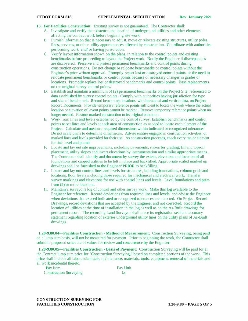
a) Thickness: Where the average thickness of the lift exceeds that shown on the plans beyond the
tolerances shown in Table 4.06-3, the Engineer will calculate the thickness adjustment in accordance
with 4.06.04.
TABLE 4.06-3: Thickness Tolerances
Mixture Designation Lift Tolerance
S1 +/- 3/8 inch
S0.25, S0.375, S0.5 +/- 1/4 inch
Where the thickness of the lift of mixture is less than that shown on the plans beyond the tolerances
shown in Table 4.06-3, the Contractor, with the approval of the Engineer, shall take corrective action
in accordance with this Section.
b) Area: Where the width of the lift exceeds that shown on the plans by more than the specified
thickness, the Engineer will calculate the area adjustment in 4.06.04.
c) Delivered Weight of Mixture: When the delivery ticket shows that the truck exceeds the allowable
gross weight for the vehicle type, the Engineer will calculate the weight adjustment in accordance
with 4.06.04.
Transverse Joints: All transverse joints shall be formed by saw-cutting to expose the full thickness of the
lift. Tack coat shall be applied to the sawn face immediately prior to additional mixture being placed.
Compaction: The Contractor shall compact the mixture to meet the density requirements as stated in
4.06.04 for any lift placed with a thickness of 1 1/2 inches or greater, and eliminate all roller marks without
displacement, shoving, cracking, or aggregate breakage. This shall include wedge courses when the wedge
thickness is 1 1/2 inches or greater within a single paver pass.
When placing a lift with a specified thickness less than 1 1/2 inches the Contractor shall provide a
minimum rolling pattern as determined by the development of a compaction curve. This shall include
wedge courses when the wedge or any portion of the wedge thickness is less than 1 1/2 inches within a
single paver pass. The procedure to be used shall be documented in the Contractor’s QCP for placement
and demonstrated on the first day of placement.
The use of the vibratory system on concrete structures is prohibited. When approved by the Engineer, the
Contractor may operate a roller using an oscillatory system at the lowest frequency setting.
If the Engineer determines that the use of compaction equipment in the dynamic mode may damage
highway components, utilities or adjacent property, the Contractor shall provide alternate compaction
equipment.
Rollers operating in the dynamic mode shall be shut off when changing directions.
These allowances will not relieve the Contractor from meeting pavement compaction requirements.
Surface Requirements:
Each lift of the surface course shall not vary more than 1/4 inch from a Contractor-supplied 10 foot
straightedge. For all other lifts of bituminous concrete, the tolerance shall be 3/8 inch. Such
tolerance will apply to all paved areas.
Any surface that exceeds these tolerances shall be corrected by the Contractor at its own expense.
Replace “Method II – Butt Joint” under Subarticle 4.06.03-7 with the following:
Method II - Butt Joint:
When adjoining passes are placed, the Contractor shall use the end gate to create a near vertical edge
(refer to Figure 4.06-2). The completing pass (hot side) shall have sufficient mixture so that the compacted
thickness is not less than the previous pass (cold side). During placement of multiple lifts, the longitudinal
joint shall be constructed in such a manner that it is located at least 6 inch from the joint in the lift
immediately below. The joint in the final lift shall be at the centerline or at lane lines. The end gate on the
paver should be set so there is an overlap onto the cold side of the joint.
When using this method, the Contractor must complete full width “curb to curb” paving when the vertical
edge exposed to traffic would be greater than one inch, unless otherwise allowed by the Engineer.

CTDOT FORM 818 SUPPLEMENTAL SPECIFICATION Rev. January 2021
BITUMINOUS CONCRETE 4.06 – PAGE 3 OF 3
Replace paragraphs 10, 11 and 12 under Subarticle 4.06.03-8 with the following:
Approval of any QCP does not relieve the Contractor of its responsibility to comply with the Project
specifications. The Contractor may propose modifications to the QCPs as work progresses and must
document the changes in writing prior to resuming operations. These modifications include changes in
quality control procedures, equipment, or personnel.
QCP for Production: Refer to M.04.03-1.
QCP for Placement: The Standard QCP, Project Summary Sheet, and Extended Season Paving Plan shall
conform to the format provided on the Advisory Team web page.
Replace Subarticle 4.06.03-9 with the following:
9. Temperature and Seasonal Requirements: Paving, including placement of temporary pavements,
shall be divided into 2 seasons, “In-Season” and “Extended-Season.” In-Season paving occurs from May 1
to October 14, and Extended Season paving occurs from October 15 to April 30. The following
requirements shall apply unless otherwise authorized or directed by the Engineer:
Mixtures shall not be placed when the air or subbase temperature is less than 40°F regardless of
the season.
Should paving operations be scheduled during the Extended Season, the Contractor must submit
an Extended Season Paving Plan for the Project that addresses minimum delivered mix
temperature and meets the requirements of Table M.04.03-4. The Plan shall also include if WMA,
PMA, or other additives are being used; maximum paver speed; enhanced rolling patterns; and the
method to balance mixture delivery and placement operations. Paving during Extended Season
shall not commence until the Engineer has approved the plan.
Replace paragraphs 1 and 2 under Subarticle 4.06.03-10 with the following:
10. Field Density: The Contractor shall obtain cores in accordance with AASHTO R 67 for the
determination of mat and longitudinal joint density of bituminous concrete pavements. The Contractor’s
representative obtaining samples must be a certified NETTCP HMA Paving Inspector, NETTCP HMA
Plant Technician, or has successfully completed the HMA Field Sampling Course administered by The
Connecticut Advanced Pavement Laboratory (CAP Lab). Within three (3) calendar days of placement, mat
and joint cores shall be extracted on each lift with a specified thickness of 1 1/2 inches or more. That time
frame may be extended to a maximum of five (5) days due to inclement weather, State holidays or other
access restrictions beyond the control of the Contractor. Joint cores shall not be extracted on HMA S1.0
lifts.
The Contractor shall extract cores from random locations determined by the Engineer in accordance with
ASTM D3665. Six (6) inch diameter cores shall be extracted for all mixes. The Contractor shall
coordinate with the Engineer to witness the extraction, labeling of cores, and filling of the core holes.
Replace the last sentence in Subarticle 4.06.04-2(b)i with the following:
Additionally, any sublot with a density result below 87% is subject to evaluation under 1.06.04.
Replace the last sentence in Subarticle 4.06.04-2(b)ii with the following:
Additionally, any sublot with a density result below 87% is subject to evaluation under 1.06.04.
Replace the last sentence in Subarticle 4.06.04-2(b)iii with the following:
Additionally, any sublot with a density result below 87% is subject to evaluation under 1.06.04.

CTDOT FORM 818 SUPPLEMENTAL SPECIFICATION Rev. January 2021
RUMBLE STRIPS, REMOVAL
OF RUMBLE STRIPS 4.07 – PAGE 1 OF 5
After Section 4.06, add the following New Section 4.07:
SECTION 4.07
RUMBLE STRIPS,
REMOVAL OF RUMBLE STRIPS
4.07.01—Description
4.07.02—Materials
4.07.03—Construction Methods
4.07.04—Method of Measurement
4.07.05—Basis of Payment
4.07.01—Description: Work under this item shall consist of installing rumble strips on asphalt highway
shoulders where shown on the plans or where directed by the Engineer. Work under this item shall also consist of removing rumble strips by milling the pavement to a depth of
2 1/4 inches, disposing of pavement millings, sweeping and cleaning, applying tack coat on all surfaces
within the milled area, and placing Hot-Mix Asphalt (HMA) or an equivalent Polymer Modified Asphalt
(PMA) to match the elevation of the surrounding pavement.
4.07.02—Materials: Materials for the removal of rumble strips shall meet the requirements of Section
M.04 and shall consist of the following:
1. HMA S0.375 or an equivalent PMA. All HMA or PMA shall be Traffic Level 2 unless indicated
otherwise on the plans.
2. Material for Tack Coat.
4.07.03—Construction Methods:
I. Installation of Rumble Strips:
The Contractor shall pre-mark the location of the edge of the cut, and the beginning and ending
points of the sections, prior to the installation of the rumble strips. The Engineer will review and
approve the locations.
The Contractor shall arrange for a technical representative, from the company which produces the
milling machine to be used on the Project, who will be required to be on Site at the beginning of the
operation in order to ensure results that meet the requirements of the Contract to the satisfaction of
the Engineer.
Rumble strips shall not be installed on bridge decks, in acceleration and deceleration lanes, at
drainage structures, at loop detector sawcut locations, or in other areas identified by the Engineer.
a. Automated (Wide Shoulders): The equipment shall be able to install the rumble strips in
sections where the shoulder width from the edge line to an obstruction is greater than or equal
to 4 feet. Where there are no obstructions, the equipment shall be used in sections where the
shoulder width from the edge line is a minimum of 3 feet. The equipment shall consist of a
rotary type cutting head with a maximum outside diameter of 24 inches and shall be a
minimum of 16 inches long. The cutting head(s) shall have the cutting tips arranged in such a
pattern as to provide a relatively smooth cut (approximately 1/16 of an inch between peaks
and valleys) in one pass. The cutting head(s) shall be on independent suspension from that of
the power unit to allow the tool to self-align with the slope of the shoulder or any
irregularities in the shoulder surface. The equipment shall include suitable provisions for the
application of water to prevent dust. The Contractor shall use a machine capable of creating
the finished pattern at a minimum output of 60 rumble strips per minute.
b. Manual (Narrow Shoulders): The equipment shall be able to install the rumble strips in
sections where the shoulder width from the edge line to an obstruction is between 3 feet and 4
feet. The cutting head(s) shall have the cutting tips arranged in such a pattern as to provide a
relatively smooth cut (approximately 1/16 of an inch between peaks and valleys) in one pass.
The equipment shall include suitable provisions for the application of water to prevent dust.
c. Finished Cut (Automated or Manual): The rumble strips shall have finished dimensions of
7 inches (+/- 1/2 inch) wide in the direction of travel and shall be 16 inches (+/- 1/2 inch) long
measured perpendicular to the direction of travel. The depressions shall have a concave
circular shape with a minimum 1/2 inch depth at center (maximum allowable depth is 5/8 inch
measured to a valley). The rumble strips shall be placed in relation to the roadway according

CTDOT FORM 818 SUPPLEMENTAL SPECIFICATION Rev. January 2021
RUMBLE STRIPS, REMOVAL
OF RUMBLE STRIPS 4.07 – PAGE 2 OF 5
to the patterns shown in the plans or in Figure 4.07-1. Alignment of the edge of the cut shall
be checked and verified by the Engineer.
The cutting tool shall be equipped with guides to provide consistent alignment of each cut in
relation to the roadway.
The Contractor shall pick up any waste material resulting from the operation in a manner
acceptable to the Engineer. This waste material shall be disposed of in accordance with Article
1.10.03.
The work area shall be returned to a debris-free state prior to re-opening to traffic.
The Contractor shall provide all traffic control as specified in the item “Maintenance and Protection
of Traffic” included elsewhere in the Contract.
II. Removal of Rumble Strips:
Equipment for this work shall include the following:
1. Milling machine: A milling machine designed and built for milling flexible pavements. It
shall be self-propelled with sufficient power, traction, and stability to maintain depth and
slope and shall be capable of removing the existing bituminous concrete pavement.
The rotary drum of the machine shall use carbide or diamond-tipped tools. A tooth spacing
of 8 mm is preferred, but up to 15 mm will be allowed. The forward speed of the milling
machine shall be a maximum of 45 feet/minute. The tools on the revolving cutting drum must
be continually maintained and shall be replaced as warranted to provide a uniform pavement
texture.
The machine shall be equipped with an integral pickup and conveying device to immediately
remove milled material from the surface of the roadway and discharge the millings into a
truck in one operation. The machine shall also be equipped with a means of effectively
limiting the amount of dust escaping from the milling and removal operation. When milling
smaller areas or areas where it is impractical to use the above described equipment, the
Contractor may be permitted to use a lesser-equipped milling machine, if approved by the
Engineer. It shall be capable of milling a minimum width of 20 inches to completely remove
the existing rumble strip. A wider milling width may be used in cases where two rumble strips
are located near and parallel to each other, as may occur in a median area.
2. 10-foot straight edge.
3. Sweeper: A sweeper, equipped with a water tank, capable of remove millings and loose debris
from the surface. Other sweeping or vacuum type equipment may be provided in lieu of the
sweeper where acceptable by the Engineer. A hand broom may be used for smaller areas
when approved by the Engineer.
4. Air compressor: An air compressor capable of producing 100 psi oil free compressed air for
cleaning the milled pavement surface.
5. Hot air lance: A hot air lance that can deliver 100 psi oil free heated air to clean and dry the
pavement surface. The compressed air emitted from the tip of the lance shall achieve a
temperature of at least 1500°F.
6. Paving and compaction equipment: Paving and compaction equipment meeting the
requirements of Section 4.06. It is expected that much of the placement will require hand
work or a mixture of equipment and hand tools to achieve the required results. Smaller
compaction equipment, including vibratory plate compactors, will be allowed by the Engineer
to achieve the required results. At all times the Contractor is required to meet the density and
compaction and all other requirements specified in Sections 4.06 and M.04.
7. Portable lighting equipment: If the work is performed at night a truck-towed light tower and
driver shall be provided for use by the Engineer for all marking, installation, and inspection of
the patches.
8. Tack Coat Distributor: A minimum 150-gallon capacity tank that is trailer mounted or self-
propelled and capable of applying tack coat meeting the requirements of Section 4.06.
The Contractor shall mark the location of the beginning and ending points of the sections for milling
and paving, prior to the removal of the rumble strips. The Engineer will review and approve the limits
of removal.
The width of milling shall be as specified on the Plans or other specifications. If no other width
specification exists, the minimum width of milling for freeway shoulders shall be 20 inches, and for all
other rumble strips the minimum width of milling shall be 14 inches in order to completely remove

CTDOT FORM 818 SUPPLEMENTAL SPECIFICATION Rev. January 2021
RUMBLE STRIPS, REMOVAL
OF RUMBLE STRIPS 4.07 – PAGE 3 OF 5
the existing rumble strip to the satisfaction of the Engineer. If there are two rumble strips located
near and parallel to one another, as may occur in median areas, and if they both can be removed by a
single pass of a wider milling machine without adversely affecting drainage, safety, or quality of
results, then a wider milling machine may be used. In this case the length measured for payment will
be the sum of the lengths of the two individual rumble strips. Milling widths wider than specified
above may be used with the written permission of the Engineer.
The depth of removal shall be 2 1/4 inches. The Engineer may alter the milling depth, either up or
down, based on deterioration or scabbing discovered as work is in progress. This adjustment will not
exceed 1/2 inch. It is expected that the milling depth of 2 1/4 inches is appropriate for most cases.
The milled surface shall be swept clean (by hand if necessary). Once all millings are removed by
sweeping, the milled areas shall be allowed to dry. Any moisture in or on the milled areas must be
allowed to evaporate or be removed with the assistance of a hot air lance as specified above. When the
milled area is dry to the satisfaction of the Engineer, it shall be blown clean of any residual dust or
debris using compressed air.
Once deemed clean and dry by the Engineer, the entire milled area, including the sides/walls of the
milled area, shall receive an application of tack coat as specified above and in Section 4.06.
After the tack coat has had sufficient time to cure or break, HMA S0.375 (Traffic Level 2) or an
equivalent PMA shall be placed and compacted to the requirements above and in Section 4.06. The
Contractor shall confirm that the surface elevation of the finished patch matches the elevation of the
surrounding pavement surface to within 1/4 inch using the 10-foot straightedge. The Contractor shall
confirm that all patch material placed is uniform in appearance without segregation.
The Contractor shall resurface the milled area prior to opening the roadway to traffic. The milled area
shall be swept, cleaned, tacked, and repaved in the same work shift.
Precautions shall be taken to avoid damage to the existing roadway materials that are to remain in
place. If damage occurs, it must be repaired by the Contractor at no additional cost to the State. The
methods employed in performing the work and all equipment, tools, machinery and plant used in
handling material and executing any part of the work shall be subject to the approval of the Engineer
before the work is started; and whenever found unsatisfactory, it shall be changed and improved as
required by the Engineer.
The Contractor shall remove and dispose of any waste material resulting from the operation in a
manner acceptable to the Engineer. This waste material shall be disposed of in accordance with Article
1.10.03.
4.07.04—Method of Measurement: The work for installing and removing rumble strips will be
measured for payment by the actual number of linear feet of rumble strips installed or removed, as applicable.
Removal distance shall be measured longitudinally along the edge of pavement with deductions for bridge
decks, acceleration and deceleration lanes, drainage structures, loop detector sawcut locations, and other
sections where the rumble strips were not previously installed.
If two rumble strips are near one another and are removed by a single milling machine pass, the length
measured for payment will be the sum of the lengths of the two rumble strips.
4.07.05—Basis of Payment: The work for installing rumble strips will be paid for at the Contract unit
price per linear foot for "Rumble Strips –Automated" or “Rumble Strips–Manual.” The price shall include
furnishing all equipment, tools, labor, a technical representative and work incidental thereto and also
disposal of any waste material resulting from the operation. The Contractor will not be paid under the item
"Rumble Strips - Manual" if the field conditions allow for the use of the "Rumble Strips - Automated" item,
even if the manual method was used.
The work for removing rumble strips will be paid for at the Contract unit price per linear foot for "Removal
of Rumble Strips." The price shall include the removal of the existing rumble strips by milling, sweeping,
cleaning, and drying of the milled area, furnishing all materials, application of tack coat, placement and
compaction of the HMA or PMA, and equipment, tools, labor, and work incidental thereto, as well as
removal and disposal of any waste material resulting from the operation.
Pay Item Pay Unit
Rumble Strips–Automated l.f.
Rumble Strips–Manual l.f.
Removal of Rumble Strips l.f.

90°
SH
OU
LD
ER
PAVEMENT EDGE LINE
TRAVEL LANE
LOCATION DETAIL (TYP.)
LEFT SHOULDER
12" +/- 1/2"
6" +/- 1/2"
RUMBLE STRIPS (TYP.)
Figure 4.07-1: DETAILS AND SECTIONS OF RUMBLE STRIPS
90°
SH
OU
LD
ER
PAVEMENT EDGE LINE
TRAVEL LANE
LOCATION DETAIL (TYP.)
RIGHT SHOULDER
12" +/- 1/2"
12" +/- 1/2"
RUMBLE STRIPS (TYP.)
12" R.
SECTION A-A
7" +/- 1/2"
5/8" MAX.
1/2" MIN.
NOTES:
RUMBLE STRIP ALIGNMENT SHALLGENERALLY BE STRAIGHT ANDOFFSET APPROXIMATELY 6" IN THELEFT SHOULDER AND 12" IN THERIGHT SHOULDER FROM THE OUTEREDGE OF THE EDGE LINE, AND SHALLBE AT LEAST 12" FROM THELONGITUDINAL JOINT IN COMPOSITEPAVEMENTS. THIS OFFSET MAY BEADJUSTED TO ACCOMMODATEVARIATIONS IN THE EDGE LINE ANDTHE SHOULDER WIDTH.
A A
PLAN DETAIL
16" +/- 1/2"
7" +/- 1/2"

Figure 4.07-2: TYPICAL TREATMENTS FOR INSTALLING RUMBLE STRIPS
RUMBLE STRIPS IN LEFT SHOULDER, IF APPLICABLE
OF DECELERATION LANE
BEGINNING OF TAPER
END RUMBLE STRIPS AT
OF ACCELERATION LANE
AT END OF TAPER
RESUME RUMBLE STRIPS
END OF PHYSICAL GORE
AND END RUMBLE STRIPS AT
BEGINNING OF PHYSICAL GORE
RESUME RUMBLE STRIPS AT
DIRECTION OF TRAFFIC
TYPICAL TREATMENT FOR RAMPS
TYPICAL TREATMENT FOR BRIDGES
3' MIN. 3' MIN.
3' MIN.3' MIN.
BRIDGES
AS NEEDED FOR NARROW SHOULDERS APPROACHING
NOTE: REVISE DISTANCE FROM EXPANSION JOINT
RUMBLE STRIPS (TYP.) RUMBLE STRIPS (TYP.)
PAVEMENT EDGE LINE
TYPICAL TREATMENT FOR OBSTRUCTIONS
1
1
1.5'1.5'
ALONG SHOULDER
CONTINUE RUMBLE STRIPS
FOR DISTANCES OF 3' OR MORE,
(I.E. CATCH BASINS OR MANHOLES)
TYPICAL TREATMENT FOR
LOOP DETECTOR SAWCUT LOCATIONS
1.5' (TYP.)

CTDOT FORM 818 SUPPLEMENTAL SPECIFICATION Rev. July 2020
MILLING,
REMOVAL OF EXISTING WEARING SURFACE 4.09 – Page 1 of 4
SECTION 4.09
MILLING,
REMOVAL OF EXISTING WEARING SURFACE
Replace Section 4.09 in its entirety with the following:
SECTION 4.09
MILLING,
REMOVAL OF EXISTING WEARING SURFACE
4.09.01—Description: This work shall consist of the milling, removal, and disposal of existing
bituminous concrete pavement. It shall also include the complete removal and disposal of the existing
bituminous concrete wearing surface, membrane waterproofing and bond breaker covering the
reinforced concrete bridge deck(s) as shown on the plans or as ordered by the Engineer. The types of
milling shall include the following:
1. Coarse Milling shall be used for the removal of bituminous concrete in excess of 4 inch depth.
2. Fine Milling shall be used to remove bituminous concrete from 0 to 4 inches. It may also be
used to remove bituminous concrete greater than 4 inches in limited areas or where required.
3. Removal of Existing Wearing Surface shall be used where shown on the plans.
4.09.03—Construction Methods:
A. Milling:
1. General: The Contractor shall remove the bituminous concrete material using the milling
type specified on the Plans. The pavement surface shall be removed to the line, grade, and
existing or typical cross-section shown on the plans or as directed by the Engineer.
The bituminous concrete material shall be disposed of offsite by the Contractor at an approved
disposal facility unless otherwise stated in the Contract.
Any milled surface, or portion thereof, that is exposed to traffic shall be paved within 14
calendar days unless otherwise stated in the Contract.
2. Equipment: The equipment for milling the pavement surface shall be designed and built for
milling bituminous concrete pavements. It shall be self-propelled with sufficient power, traction,
and stability to maintain depth and slope and shall be capable of removing the existing bituminous
concrete pavement.
The milling machine shall be equipped with a built-in automatic grade averaging control system
that can control the longitudinal profile and the transverse cross-slope to produce the specified
results. The longitudinal controls shall be capable of operating from any longitudinal grade
reference, including string line, mobile reference beam (20 feet minimum), or mobile string line (30
feet minimum). The transverse controls shall have an automatic system for controlling cross-slope
at a given rate. The Engineer may waive the requirement for automatic grade or slope controls
where the situation warrants such action.
The machine shall be equipped with an integral pickup and conveying device to immediately
remove material being milled from the surface of the roadway and discharge the millings into a
truck, all in one operation. The machine shall also be equipped with a means of effectively limiting
the amount of dust escaping from the milling and removal operation.
When milling smaller areas or areas where it is impractical to use the above described equipment,
the use of a lesser equipped milling machine may be permitted when approved by the Engineer.
The rotary drum of the milling machine shall have carbide or diamond-tipped teeth with the
following maximum spacing and minimum milling depth:
Milling Type Maximum
Tooth Spacing*
Minimum Depth
Capability
(single pass) Coarse Milling 15 mm 4 inches
Fine Milling 8 mm 4 inches
* Industry standard units
CTDOT FORM 818 SUPPLEMENTAL SPECIFICATION Rev. July 2020
MILLING,
REMOVAL OF EXISTING WEARING SURFACE 4.09 – Page 2 of 4
The forward speed of any milling machine shall be limited to no more than 45 feet/minute.
The teeth on the revolving cutting drum must be continually maintained and shall be replaced as
warranted to provide a uniform pavement texture, as outlined in 4.09.03-C, Surface Tolerance.
3. Protection: Protection shall be provided around visible existing catch basin inlets,
manholes, utility valve boxes, and any similar structures. Any damage to such structures as a
result of the milling operation is the Contractor’s responsibility and shall be repaired at the
Contractor’s expense.
To prevent the infiltration of milled material into the storm drainage system, the Contractor shall
take special care to prevent the milled material from falling into the inlet openings or inlet grates.
Any milled material that falls into inlet openings or inlet grates shall be removed at the
Contractor’s expense.
B. Removal of Existing Wearing Surface: The bituminous concrete wearing surface,
membrane waterproofing and bond breaker shall be removed from the structure(s) using means
acceptable to the Engineer to completely expose the concrete bridge deck(s).
Prior to removal of bituminous concrete wearing surface, the Contractor shall field verify the depth of
the existing bituminous concrete by obtaining depth measurements (maximum 4 inch diameter holes) at
intervals no greater than 25 feet apart in each lane. Depth verification holes shall be filled with
bituminous material and compacted if the removal of wearing surface operation will not be completed
within 5 days.
The existing bituminous concrete wearing surface and membrane waterproofing shall be removed in
their entireties to the limits shown on the plans. The removal operations shall not begin until the
Contractor is prepared to perform the permanent patching or repair to the underlying concrete within 5
working days. If this is in conflict with "Prosecution and Progress," "Maintenance and Protection of
Traffic," or other Contract requirements, the more stringent specification shall apply.
Methods for removal of existing wearing surfaces shall be fine milling and shall include as many passes
or amount of effort required to completely expose the concrete deck(s). Any membrane not completely
removed by the milling process shall be removed by scarifying or other means as approved by the
Engineer.
Alternate methods for the removal of a bituminous concrete surface may be submitted to the Engineer
for review. Demonstration of the alternate removal methods may be required prior to consideration.
The existing bituminous concrete wearing surface, membrane waterproofing, bond breaker, and any
other products being removed shall be disposed of offsite by the Contractor unless otherwise noted in
the Contract or as directed by the Engineer.
If membrane waterproofing, as specified elsewhere in the Contract, is to be re-installed on the
existing deck(s), the surface profile following removal shall be suitable for such reinstallation. The
profile of the cleaned concrete surface shall meet the membrane waterproofing manufacturer’s
recommendations, and have no gouges greater than 1/2 inch in depth. Any deficiencies that could, in
the Engineer’s opinion, cause failure of, or puncture the new membrane shall be removed as part of
this work.
C. Surface Tolerance:
1. General: The surface shall be free from gouges, longitudinal grooves and ridges, oil film, and
other imperfections, that are a result of defective equipment, improper use of equipment, poor
workmanship, or inadequate field verification. Any unsatisfactory surfaces caused by the removal
operations are the Contractor’s responsibility and shall be corrected at the Contractor’s expense
and to the satisfaction of the Engineer prior to opening the surface to traffic.
Any raised structures shall be delineated with traffic control devices, as directed by the Engineer.
2. Tolerances: All milling types shall provide a satisfactory riding surface with a uniform
textured appearance. The Contractor shall perform random spot-checks at a minimum of 5
locations per working shift with a Contractor-supplied 10 foot straight edge to verify the surface
tolerances listed below. Random spot-checks (minimum of 5 checks per shift) shall occur at a
maximum of 250 feet per pass of the milling machine and shall be performed with the Engineer
present. The following tolerances shall apply:

CTDOT FORM 818 SUPPLEMENTAL SPECIFICATION Rev. July 2020
MILLING,
REMOVAL OF EXISTING WEARING SURFACE 4.09 – Page 3 of 4
(a) Coarse Milling: The variation of the top of two ridges from the testing edge of the
straightedge, between any two ridge contact points, shall not exceed 3/8 inch. The variation of
the top of any ridge to the bottom of the groove adjacent to that ridge shall not exceed 3/8 inch.
(b) Fine Milling: The variation of the top of two ridges from the testing edge of the
straightedge, between any two ridge contact points, shall not exceed 1/4 inch. The variation of
the top of any ridge to the bottom of the groove adjacent to that ridge shall not exceed 1/4 inch.
Where a surface delamination between bituminous concrete layers or a surface delamination of
bituminous concrete on Portland cement concrete causes a non-uniform texture to occur, the depth of
milling shall be adjusted in small increments to a maximum of +/- 1/2 inch to eliminate the condition.
When removing bituminous concrete pavement entirely from an underlying Portland cement concrete
pavement, all bituminous concrete pavement shall be removed leaving a uniform surface of Portland
cement concrete, unless otherwise directed by the Engineer.
Any unsatisfactory surfaces produced by the milling operation are the Contractor’s responsibility and
shall be corrected at the Contractor’s expense and to the satisfaction of the Engineer.
D. Transitions:
1. Construction Joints: No transverse vertical face shall be left exposed to traffic. No
longitudinal vertical face greater than 1 inch shall be left exposed to traffic. Any other vertical
face created by milling shall have a bituminous concrete taper constructed to the temporary
transition requirements as described below.
2. Roadway Structures: Roadway structures shall not have a vertical face of greater than 1
inch exposed to traffic as a result of milling. All roadway structure edges and bituminous
concrete tapers shall be clearly marked with fluorescent paint. The paint shall be maintained
throughout the exposure to traffic.
All structures within the roadway that are exposed to traffic and greater than 1 inch above
the milled surface shall receive a transition meeting the following requirements:
(a) For roadways with a posted speed limit of 35 mph or less:
(i) Round structures with an exposed vertical face between 1 inch and 2.5 inches shall
be transitioned with a hard rubber tapered protection ring designed for that purpose
of the appropriate inside diameter designed specifically to protect roadway
structures. Bituminous concrete tapers at a minimum 12 to 1 (12:1) taper in all
directions may be substituted for the protection rings if approved by the Engineer.
(ii) Round structures with an exposed vertical face greater than 2.5 inches shall receive a
transition of bituminous concrete formed at a minimum 12 to 1 (12:1) taper in all
directions.
(iii) All rectangular structures shall receive a transition of bituminous concrete formed
at a minimum 12 to 1 (12:1) taper in all directions.
(b) For roadways with a posted speed limit of 40, 45 or 50 mph: All structures shall
receive a transition of bituminous concrete formed at a minimum 24 to 1 (24:1) taper
in all directions of travel. Direction of travel shall include both the leading and trailing
sides of a structure. The minimum taper shall be 12 to 1 (12:1) in all other directions.
(c) For roadways with a posted speed limit of greater than 50 mph: All structures shall
receive a transition of bituminous concrete formed at a minimum 36 to 1 (36:1) taper in
the direction of travel. Direction of travel shall include both the leading and trailing sides
of a structure. The minimum taper shall be 12 to 1 (12:1) in all other directions.
3.Temporary Transitions: If any vertical face is formed in an area exposed to traffic, a
temporary paved transition shall be established according to the requirements shown on the plans
or in accordance with 4.06.03-5, “Transitions for Roadway Surface.” If a milling machine is used
to form a temporary transition, the length of the temporary transition shall be in accordance with
4.06.03-5, the requirements shown on the plans, or shall be as directed by the Engineer. A clean
vertical face shall be established by saw cutting at all final termini limits of the Project.
4. Milling for Permanent Pavement Transitions: When called for on the plans, milling a
tapered “keyway” to transition the top course of a bituminous concrete overlay to an existing

CTDOT FORM 818 SUPPLEMENTAL SPECIFICATION Rev. July 2020
MILLING,
REMOVAL OF EXISTING WEARING SURFACE 4.09 – Page 4 of 4
pavement shall be performed as specified elsewhere in the Contract.
E. Sweeping: Prior to opening an area which has been milled to traffic, the pavement shall be
thoroughly swept with a sweeper truck. The sweeper truck shall be equipped with a water tank and be
capable of removing the millings and loose debris from the surface. The sweeper truck shall operate at
a speed that allows for the maximum pickup of millings from the roadway surface. Other sweeping
equipment may be provided in lieu of the sweeper where acceptable by the Engineer.
Any milled area that will not be exposed to live traffic for a minimum of 48 hours prior to paving shall
require a vacuum sweeper truck in addition to, or in lieu of, mechanical sweeping. The vacuum
sweeper truck shall have sufficient power and capacity to completely remove all millings from the
roadway surface including any fine particles within the texture of the milled surface. Vacuum sweeper
truck hose attachments shall be used to clean around pavement structures or areas that cannot be
reached effectively by the main vacuum. Compressed air may be used in lieu of vacuum attachments if
approved by the Engineer.
4.09.04—Method of Measurement:
Milling of bituminous concrete will be measured for payment by the number of square yards of area
from which the particular type of milling has been completed and the work accepted. Deductions will
not be made for minor unmilled areas such as catch basin inlets, manholes, utility boxes and any similar
structures.
The removal of wearing surface will be measured for payment by the number of square yards of
bituminous concrete wearing surface removed to expose the underlying concrete deck(s). No area
deductions will be made for scuppers, joints, and any similar areas.
There will be no measurement for marking roadway structures, transitions for roadway structures
and sweeping of any surface that has been milled.
4.09.05—Basis of Payment: Milling work will be paid for at the Contract unit price per square yard
for “Fine Milling of Bituminous Concrete (0” to 4”),” “Coarse Milling of Bituminous Concrete
(Greater Than 4” Up To 8”),” and “Coarse Milling of Bituminous Concrete (Greater Than 8”).” This
price shall include all equipment, tools, labor, and materials incidental thereto. No additional
payments will be made for multiple passes with the milling machine(s).
Work for the removal of wearing surface will be paid for at the Contract unit price per square yard
for “Removal of Existing Wearing Surface," complete and accepted, which price shall include the
field verification, removal of wearing surface, removal of membrane waterproofing and bond
breaker, saw cutting, and all equipment, tools and labor. No additional payments will be made for
multiple passes with the milling machine(s) to remove the wearing surface.
No separate payments will be made for cleaning the pavement prior to paving; providing protection
and doing handwork to remove bituminous concrete around catch basin inlets, bridge scuppers,
manholes, utility valve boxes, median barriers, parapets, joints and any similar structures; repairing
surface defects as a result of Contractor negligence; providing protection to underground utilities from
the vibration of the milling operation; removal of any temporary milled transition; removal and disposal
of millings; sweeping and all associated work.
Milling for Pavement Transitions, where identified on the plans, will be paid under a separate
item specified elsewhere.
Installation of traffic control devices shall be included under the costs for “Maintenance and Protection
of Traffic,” payment for the devices will be under the applicable items.
Pay Item Pay Unit
Fine Milling of Bituminous Concrete (0” to 4”) s.y.
Coarse Milling of Bituminous Concrete (Greater Than 4” Up To 8”) s.y.
Coarse Milling of Bituminous Concrete (Greater Than 8”) s.y.
Removal of Existing Wearing Surface s.y.
CTDOT FORM 818 SUPPLEMENTAL SPECIFICATION Rev. July 2021
REINFORCING STEEL 6.02 – PAGE 1 OF 1
SECTION 6.02
REINFORCING STEEL
Replace Subarticle 6.02.03-4b with the following:
(b) Support Systems: Reinforcing steel shall be supported in its proper position by use of precast
mortar blocks, wire bar supports, supplementary bars (tie-down bars), side form spacers or other approved
devices. Such devices shall be sufficiently strong and properly placed at frequent intervals so as to
maintain the cover between the reinforcing and the surface of the concrete. When non-galvanized steel
forms are proposed to be used adjacent to galvanized reinforcing bars, non-conductive materials shall be
used for bar supports, side form spacers and any other device that could electrically connect the reinforcing
to the forms. Metal devices must be properly insulated to protect against electrical conduction.
The reinforcing steel cover shall be no less than that shown on the plans and no greater than that shown
plus 1/4 inch.
Platforms for the support of workers and equipment during concrete placement shall be supported directly
on the forms and not on the reinforcing steel.
Replace Subarticle 6.02.03-4d with the following:
(d) Wire Supports: Wire bar supports, such as ferrous metal chairs and bolsters, shall conform to
industry practice as described in the CRSI "Manual of Standard Practice of the Concrete Reinforcing Steel
Institute." All bolsters or chairs which bear against the forms for exposed surfaces shall be equipped with
snug fitting, high density, polyethylene tips which provide 1/2-inch minimum clearance between the metal
and any exposed surface. For epoxy-coated reinforcement, all wire bar supports and bar clips shall be
epoxy or plastic coated. For galvanized reinforcement, chair and bar supports shall be hot-dip galvanized,
after fabrication, in accordance with ASTM A123. Chair and bar supports between galvanized reinforcing
and non-galvanized metal forms shall be made of non-conductive materials. Metal devices must be
properly insulated to protect against electrical conduction. The maximum spacing of slab bolster rows and high chair rows for concrete deck slabs shall be 4 feet
unless otherwise directed by the Engineer.

CTDOT FORM 818 SUPPLEMENTAL SPECIFICATION Rev. January 2021
STRUCTURAL STEEL 6.03 – PAGE 1 OF 1
SECTION 6.03
STRUCTURAL STEEL
Replace Subarticle 6.03.03-4(b) with the following:
(b) Camber: All members shall be cambered prior to heat curving and painting. Rolled beams shall be
either heat or cold cambered by methods approved by the Engineer. Cold cambering shall not be
performed on fracture critical rolled sections, such as beams spaced more than 12 feet on center. For
beams with excessive camber requirements (more than 1 1/2 inches per 20 feet of length), cold
cambering is prohibited. Plate girders shall be cambered by cutting the web to the prescribed shape
with allowances for shrinkage due to cutting, welding, and heat curving. The fabricator is
responsible to determine what allowances should be made. Rolled, plate-rolled, or fabricated
sections shall be cambered to the total amount shown on the plans and within the camber deviation
tolerances permitted for welded beams and girders, as indicated in the ANSI/AASHTO/AWS D1.5
Bridge Welding Code. The Contractor must submit to the Engineer for approval, a cambering
procedure that includes a plan for corrective action if the actual camber is not within tolerance.

CTDOT FORM 818 SUPPLEMENTAL SPECIFICATION Rev. July 2021
DRAINAGE PIPES, DRAINAGE PIPE ENDS 6.86 – PAGE 1 OF 1
SECTION 6.86
DRAINAGE PIPES, DRAINAGE PIPE ENDS
Add the following after the last paragraph of Subarticle 6.86.03-3:
Material placed around pipes shall be deposited on both sides to approximately the same elevation at
the same time, in accordance with 2.86.03.

CTDOT FORM 818 SUPPLEMENTAL SPECIFICATION Rev. July 2021
MEMBRANE WATERPROOFING
(WOVEN GLASS FABRIC) 7.07 – PAGE 1 OF 1
SECTION 7.07
MEMBRANE WATERPROOFING
(WOVEN GLASS FABRIC)
Replace Section 7.07 with the following:
SECTION 7.07
MEMBRANE WATERPROOFING
(WOVEN GLASS FABRIC)
(Vacant)

CTDOT FORM 818 SUPPLEMENTAL SPECIFICATION Rev. July 2020
PAVED APRONS 8.03 – PAGE 1 OF 1
SECTION 8.03
PAVED DITCHES, PAVED APRONS AND
PAVED CHANNELS
Replace Section 8.03 in its entirety with the following:
SECTION 8.03
PAVED APRONS
8.03.01—Description
8.03.02—Materials
8.03.03—Construction Methods
8.03.04—Method of Measurement
8.03.05—Basis of Payment
8.03.01—Description: The work under this item includes placing and compacting of a bituminous
concrete course on a pre-excavated foundation forming paved aprons in accordance with the line, grade,
compacted final thickness and typical cross-section shown on the plans.
8.03.02—Materials: The materials for this work shall meet the following requirements:
Bituminous Concrete Curb Mix shall meet the requirements of 4.06 and M.04.01.
Processed Aggregate Base shall meet the requirements of M.05.01.
8.03.03—Construction Methods: The processed aggregate base course shall be placed in a single
course, 4 inches compacted thickness, in accordance with 3.04.03. The surface shall be a 2 inch course of
bituminous concrete curb mix. The bituminous concrete shall be placed and thoroughly compacted with
compaction equipment suitable for small areas.
8.03.04—Method of Measurement: The quantity to be measured for this item will be the surface area in
square yards of paved apron constructed and accepted.
Formation of Subgrade and Processed Aggregate Base will not be measured for payment.
8.03.05—Basis of Payment: This work will be paid for at the Contract unit price per square yard for
"Paved Apron." The price shall include all materials, tools, equipment and work incidental thereto.
Pay Item Pay Unit
Paved Apron s.y.

CTDOT FORM 818 SUPPLEMENTAL SPECIFICATION Rev. July 2020
PROTECTIVE COMPOUND FOR BRIDGES 8.18 – Page 1 of 1
SECTION 8.18
PROTECTIVE COMPOUND FOR BRIDGES
Delete Section 8.18 in its entirety.

CTDOT FORM 818 SUPPLEMENTAL SPECIFICATION Rev. July 2021
CONCRETE SIDEWALKS AND RAMPS 9.21 – PAGE 1 OF 1
SECTION 9.21
CONCRETE SIDEWALKS AND RAMPS
Replace the last paragraph of Article 9.21.02 with the following:
Detectable warning surfaces shall be prefabricated detectable warning tile(s) chosen from the Department’s
Qualified Products List for retrofit or cast in place applications
Replace Subarticle 9.21.03-8 with the following:
8. Detectable Warning Surface: The detectable warning surface for new construction shall be set
directly in plastic concrete and each tile shall be weighed down to prevent the tile from floating after
placement in wet concrete in accordance with curing procedures. Install detectable warning surface
according to the plans and the manufacturer’s specifications, or as directed by the Engineer.
The detectable warning surface for retrofit construction shall be installed according to the plans in the
direction of pedestrian route and contained wholly within painted crosswalk when present. Its installation
shall meet all manufacturer’s requirements.
Replace Subarticle 9.21.04-4 with the following:
4. Detectable Warning Surface: For new construction (cast in place), the detectable warning surface
will be measured for payment by the actual number of square feet of detectable warning surface installed
and accepted.
Replace the 2nd paragraph of Article 9.21.05 with the following:
A new detectable warning surface will be paid for at the Contract unit price per square foot of
“Detectable Warning Surface” installed and complete in place. This price shall include all tiles, materials,
equipment, tools and labor incidental thereto.
In the Pay Item – Pay Unit table, change “Detectable Warning Strip, ea.” as follows:
Detectable Warning Surface s.f.

CTDOT FORM 818 SUPPLEMENTAL SPECIFICATION Rev. July 2020
CONCRETE DRIVEWAY RAMP 9.24 – Page 1 of 1
SECTION 9.24
CONCRETE DRIVEWAY RAMP
Replace Section 9.24 in its entirety with the following:
SECTION 9.24
CONCRETE DRIVEWAY RAMP
9.24.01—Description: This item shall consist of concrete driveway ramps constructed on a granular fill
base in accordance with the Contract.
9.24.02—Materials: Materials for this work shall meet the following requirements:
1. Portland Cement: Concrete shall meet the requirements of M.03 for Class PCC03340 Concrete.
2. Granular Fill Base: Granular fill shall meet the requirements of M.02.01.
3. Reinforcement: Shall meet the requirements of M.06.01.
9.24.03—Construction Methods: Construction methods shall meet the requirements of 9.21.03. The
surface shall be finished and marked off as directed by the Engineer.
The Contractor shall protect the driveway ramp from damage until it is opened to traffic. The ramp shall
not be opened to traffic until the attainment of a compressive strength of 3,000 psi. Any damage occurring
prior to the Department opening the driveway ramp to traffic shall be repaired or replaced at the
Contractor’s expense.
9.24.04—Method of Measurement: This work will be measured for payment as follows:
1. Concrete Driveway Ramp: This work will be measured for payment by the actual number of cubic
yards of completed and accepted concrete driveway ramps.
2. Excavation: Excavation below the finished grade of each ramp, backfilling and disposal of surplus
material will not be measured for payment; but the cost shall be included in the Contract price for Concrete
Driveway Ramp.
Excavation above the finished grade of each ramp will be classified and paid for in accordance with 2.02.
3. Granular Fill Base: This work will not be measured for payment, but the cost shall be included in
the Contract price for Concrete Driveway Ramp.
4. Reinforcement: This material will not be measured for payment, but the cost shall be included in the
Contract price for Concrete Driveway Ramp.
9.24.05—Basis of Payment: This work will be paid for at the Contract unit price per cubic yard for
"Concrete Driveway Ramp," complete in place, which price shall include all excavation as specified above,
backfill, disposal of surplus materials, and all materials, equipment, tools and labor incidental thereto.
Pay Item Pay Unit
Concrete Driveway Ramp c.y.

CTDOT FORM 818 SUPPLEMENTAL SPECIFICATION Rev. July 2020
MAINTENANCE AND PROTECTION
OF TRAFFIC 9.71 – Page 1 of 2
SECTION 9.71
MAINTENANCE AND PROTECTION OF TRAFFIC
Replace Section 9.71 in its entirety with the following:
SECTION 9.71
MAINTENANCE AND PROTECTION OF TRAFFIC
9.71.01—Description: Unless other provisions are made on the plans or in the special provisions of the
Contract, the Contractor shall keep the roadway under construction open to traffic for the full length of the
Project and shall provide a sufficient number of travel lanes and pedestrian passways to move that traffic
ordinarily using the roadway. The travel lanes and pedestrian passways shall be drained and kept
reasonably smooth and in suitable condition at all times in order to provide minimum interference to traffic
consistent with the proper prosecution of the work.
Suitable ingress and egress shall be provided at all times where required, for all intersecting roads and for
all abutting properties having legal access.
When a scheme for maintenance of traffic, which may include detours, is shown on the plans or described
in the special provisions of the Contract, this shall govern unless an alternate scheme acceptable to the
Engineer is offered by the Contractor at no additional cost. If no scheme is shown on the plans or described
in the special provisions of the Contract, and the Contractor wishes to deviate from the provisions of
maintaining traffic as described in this Section, the Contractor may submit and the Engineer may approve a
schedule showing a proposed sequence of operations and a compatible method of maintaining traffic.
The Contractor shall provide to the Engineer the name of the person who shall be responsible for
installing and maintaining all temporary traffic control devices in work zones on limited access highways.
This person shall be certified as a Traffic Control Supervisor by ATSSA. This certification shall be
maintained and valid throughout the duration of the Contract.
9.71.03—Construction Methods: The Contractor shall furnish and erect signs legally closing the
highway to traffic, as shown on the plans or directed by the Engineer, prior to commencing any work on the
Project.
The Contractor shall furnish a sufficient number of signs, barricades, drums, traffic cones and delineators
to forewarn traffic of the construction as shown on the traffic control plans contained within or as directed
by the Engineer.
The Contractor shall also provide such safety measures, pavement markings, warning devices and signs as
deemed necessary to safeguard and guide the traveling public through detours ordered by the Engineer,
included in the approved scheme for maintenance of traffic, or as shown on the plans. The Contractor shall
erect, maintain, move, adjust, clean, relocate and store these signs, barricades, drums, traffic cones and
delineators when, where and as directed by the Engineer, and in accordance with the ATSSA "Quality
Guidelines for Temporary Traffic Control Devices and Features."
The use of unauthorized or unapproved signs, barricades, drums, traffic cones or delineators will not be
permitted.
All signs in any one signing pattern shall be mounted the same height above the traveled surface. The
Contractor shall keep all signs in proper position, clean and legible at all times. Care shall be taken so that
weeds, shrubbery, construction materials or equipment, and soil, are not allowed to obscure any sign, light,
or barricade. Signs that do not apply to existing conditions shall be removed or adjusted so that the legend
is not visible to approaching traffic.
The Contractor, when ordered by the Engineer, shall remove snow and take care of icy conditions on
temporary, new and existing sidewalks on any part of the right-of-way within the limits of the Project.
Payment for the cost thereof, will be made as extra work.
Snow removal and correction of icy conditions, other than those resulting from the Contractor's
operations, on uncompleted contracts under traffic, will remain an obligation of the State or others.
Should the Contractor fail to perform any of the work required under this section, the State may perform
or arrange for others to perform such work. In such cases, the State will deduct from money due or to
become due the Contractor all expenses connected there with which are found to be greater than the cost to
the State had the Contractor performed the specified work.
9.71.04—Method of Measurement: This item, being paid on a lump sum basis, will not be measured for
payment.

CTDOT FORM 818 SUPPLEMENTAL SPECIFICATION Rev. July 2020
MAINTENANCE AND PROTECTION
OF TRAFFIC 9.71 – Page 2 of 2
9.71.05—Basis of Payment: This work will be paid for at the Contract lump sum price for "Maintenance
and Protection of Traffic." This price shall include all costs for labor, training, equipment and services
involved in the erection, maintenance, moving, adjusting, cleaning, relocating and storing of signs,
barricades, drums, traffic cones and delineators furnished by the Contractor, as well as all costs of labor and
equipment involved in the maintenance of traffic lanes and detours, except for pavement markings, ordered
or included in the approved scheme for maintenance of traffic. This price shall also include furnishing and
services of a trained Traffic Control Supervisor for work on limited access highways.
"Maintenance and Protection of Traffic" does not include the cost of signs, barricades, drums, traffic
cones, delineators, or the furnishing and placing of materials such as borrow, gravel, crushed stone,
bituminous concrete for patching and pipe. These items will be paid for at their respective Contract unit
prices, or in the absence of applicable Contract unit prices, as extra work. If the Engineer requires the
Contractor to provide facilities in excess of the requirements of the adopted scheme for maintenance and
protection of traffic, the Contractor shall perform the required work, and payment for the cost thereof will
be made at applicable Contract unit prices, or in the absence of applicable Contract unit prices, as extra
work.
Pay Item Pay Unit
Maintenance and Protection of Traffic l.s.

CTDOT FORM 818 SUPPLEMENTAL SPECIFICATION Rev. July 2020
TRAFFIC CONE 9.77 – PAGE 1 OF 1
SECTION 9.77
TRAFFIC CONE
Replace Section 9.77 in its entirety with the following:
SECTION 9.77
TRAFFIC CONE
9.77.01—Description: Under this item the Contractor shall furnish all reflectorized orange traffic cones
required on the Project to meet the requirements as stated in the item "Maintenance and Protection of
Traffic," as shown on the plans and as directed by the Engineer.
The Contractor shall have, available on the Project, a sufficient number of traffic cones to fulfill all the
requirements as specified in the Contract and to replace those traffic cones which have become damaged.
9.77.02—Materials: Traffic cones shall be constructed of materials to a thickness to withstand impact
without damage to cones or to vehicles. The traffic cones shall be of sufficient mass or have bases to which
ballast may be added to assure that they will not be blown over or displaced by wind from passing vehicles.
Traffic cones used at night shall be reflectorized by utilizing Retroreflective Sheeting in accordance with
M.18.09.
The following documentation shall be submitted by the Contractor prior to using traffic cones on the
Project:
1. For traffic cones manufactured on or before December 31, 2019 and used for the duration of their
normal service life, a copy of the manufacturer’s self-certification that the traffic cones comply
with the requirements of the AASHTO Manual for Assessing Safety Hardware (MASH) or the
NCHRP Report 350 is required.
2. For traffic cones manufactured after December 31, 2019, a copy of the manufacturer’s self-
certification that the traffic cones comply with the requirements of the 2016 edition of the
AASHTO MASH is required.
9.77.04—Method of Measurement: This item will be measured for payment by the number of traffic
cones used on the Project.
9.77.05—Basis of Payment: This item will be paid for at the Contract unit price each for "Traffic Cone"
used on the Project. Each cone will be paid for once, regardless of the number of times it is used on the
Project.
Any traffic cones that are missing, damaged or defaced so that they are not effective, as determined by the
Engineer in accordance with ATSSA "Quality Guidelines for Temporary Traffic Control Devices and
Features," shall be replaced by the Contractor at no cost to the State.
When the traffic cones are no longer required on the Project they shall remain the property of the
Contractor.
Pay Item Pay Unit
Traffic Cone ea.
CTDOT FORM 818 SUPPLEMENTAL SPECIFICATION Rev. July 2020
TRAFFIC DRUM 9.78 – PAGE 1 OF 1
SECTION 9.78
TRAFFIC DRUM
Replace Section 9.78 in its entirety with the following:
SECTION 9.78
TRAFFIC DRUM
9.78.01—Description
9.78.02—Materials
9.78.03—Construction Methods
9.78.04—Method of Measurement
9.78.05—Basis of Payment
9.78.01—Description: Under this item the Contractor shall furnish all traffic drums required on the
Project to correspond to the traffic patterns, as indicated in the Contract for "Maintenance and Protection of
Traffic," as shown on the plans and as directed by the Engineer.
9.78.02—Materials: Traffic Drums shall be manufactured plastic or rubber devices designed in
accordance with the latest edition of the MUTCD. The design of the device will allow for the installation
of barricade warning lights. The device shall be stabilized with the use of sandbags or other approved
means.
Retroreflective Sheeting, in accordance with M.18.09, shall be used on traffic drums. Only one type
sheeting shall be used on a drum and all drums furnished on a construction project shall be manufactured
with the same type retroreflective sheeting.
The following documentation shall be submitted by the Contractor prior to using traffic drums on the
Project:
1. For traffic drums manufactured on or before December 31, 2019 and used for the duration of their
normal service life, a copy of the manufacturer’s self-certification that the traffic drums comply
with the requirements of the AASHTO MASH or the NCHRP Report 350 is required.
2. For traffic drums manufactured after December 31, 2019 and used without attachments, a copy of
the manufacturer’s self-certification that the traffic drums comply with the requirements of the
2016 edition of the AASHTO MASH is required.
3. For traffic drums manufactured after December 31, 2019 and used with attachments such as
warning lights, a copy of the Federal-Aid Eligibility Letter issued by the FHWA to the
manufacturer documenting that the traffic drums with the proposed attachments meet the crash test
and evaluation criteria of the 2016 AASHTO MASH is required.
9.78.03—Construction Methods:
The Contractor shall have, available on the Project, a sufficient number of traffic drums to fulfill all the
requirements, as specified in the Contract, to provide adequate traffic control during periods of unforeseen
circumstances or emergencies.
Traffic drums shall be designed and installed in accordance with the plans, the MUTCD latest edition, and
as directed by the Engineer.
Any traffic drum that is missing, damaged or defaced so that it is not effective, as determined by the
Engineer and in accordance with ATSSA "Quality Guidelines for Temporary Traffic Control Devices and
Features," shall be replaced by the Contractor.
When the traffic drums are no longer required on the Project, they shall remain the property of the
Contractor.
9.78.04—Method of Measurement: This work will be measured for payment by the number of traffic
drums used on the Project.
9.78.05—Basis of Payment: This item will be paid for at the Contract unit price each for "Traffic Drum"
used on the Project. Each drum will be paid for once, regardless of the number of times it is used on the
Project.
Pay Item Pay Unit
Traffic Drum ea.

CTDOT FORM 818 SUPPLEMENTAL SPECIFICATION Rev. July 2020
CONSTRUCTION BARRICADE 9.79 – Page 1 of 2
SECTION 9.79
CONSTRUCTION BARRICADE
Replace Section 9.79 in its entirety with the following:
SECTION 9.79
CONSTRUCTION BARRICADE
9.79.01—Description: Under this item the Contractor shall furnish all construction barricades of the
specified type required on the Project to comply with the requirements of NCHRP Report 350 (TL-3), or
the AASHTO MASH, and the requirements stated in the item "Maintenance and Protection of Traffic," as
shown on the plans and as directed by the Engineer.
9.79.02—Materials: Construction barricades shall consist of the following materials:
The frame shall be of polyvinyl chloride pipe meeting the requirements of ASTM D2241 for PVC 1120 or
1220, SDR 21 (pressure rating 200 psi), ASTM D3034, SDR 35 or an approved equal. All straight
members shall be the color white.
Wyes, tees and elbows for joint connections shall be polyvinyl chloride of suitable size and strength for
the purpose intended.
Joints shall not be glued and a 3/16 inch nylon rope (or equivalent) shall be threaded loosely through the
pipe to keep sections from flying if hit by a vehicle.
Face panels used as horizontal members shall be constructed of a suitable plastic material, 0.060 inch
high-impact styrene, anodized aluminum of no less than 0.025 inch thickness or a comparable substitute
approved by the Engineer.
All hardware shall be in accordance with standard commercial specifications and shall be approved by the
Engineer.
Alternate stripes of white and fluorescent orange retroreflective sheeting shall be applied to the horizontal
members as shown on the plans. Only one type sheeting shall be used on a barricade and all barricades on
a construction project shall be constructed with the same type of retroreflective sheeting. Retroreflective
sheeting shall meet the requirements of M.18.09.
Construction barricades shall be designed and fabricated so as to prevent them from being blown over or
displaced by wind. Construction barricades shall be approved by the Engineer before they are placed into
service.
Materials Certificates shall be required confirming compliance with the requirements set forth in the plans
and specifications for these barricades.
The following documentation shall be submitted by the Contractor prior to using barricades on the
Project:
1. For barricades manufactured on or before December 31, 2019 and used for the duration of their
normal service life, a copy of the Federal-Aid Eligibility Letter issued by the FHWA to the
manufacturer documenting that the barricades meet the crash test and evaluation criteria of the
AASHTO MASH or of the NCHRP Report 350 is required.
2. For barricades manufactured after December 31, 2019, a copy of the Federal-Aid Eligibility Letter
issued by the FHWA to the manufacturer documenting that the barricades meet the crash test and
evaluation criteria of the 2016 AASHTO MASH is required.
9.79.03—Construction Methods: The Contractor shall furnish a sufficient number of construction
barricades required for the traffic patterns for all operations which are being undertaken concurrently. The
barricades shall be constructed in a neat and workmanlike manner to the satisfaction of the Engineer.
Ineffective barricades, as determined by the Engineer and in accordance with ATSSA "Quality Guidelines
for Temporary Traffic Control Devices and Features," shall be replaced by the Contractor at no cost to the
State.
Barricades that are no longer required shall be removed from the Project and shall remain the property of
the Contractor.
9.79.04—Method of Measurement: This work will be measured for payment by the number of
construction barricades used on the Project.
9.79.05—Basis of Payment: This item will be paid for at the Contract unit price each for "Construction
Barricade" of the type specified and used on the Project. Each barricade will be paid for once, regardless of

CTDOT FORM 818 SUPPLEMENTAL SPECIFICATION
CONSTRUCTION BARRICADE 9.79 – Page 2 of 2
the number of times it is used on the Project.
Pay Item Pay Unit
Construction Barricade (Type) ea.

CTDOT FORM 818 SUPPLEMENTAL SPECIFICATION Rev. July 2020
42 INCH TRAFFIC CONE 9.81 – PAGE 1 OF 1
SECTION 9.81
42 INCH TRAFFIC CONE
Replace Section 9.81 in its entirety with the following:
SECTION 9.81
42 INCH TRAFFIC CONE
9.81.01—Description: This item shall consist of furnishing 42-inch retroreflective traffic cones required
on the Project to meet the requirements of the traffic control plans, as stated in the item "Maintenance and
Protection of Traffic," as shown on the plans or as directed by the Engineer.
The Contractor shall have available on the Project a sufficient number of traffic cones to fulfill all the
requirements as specified in the Contract and to replace those which have become damaged.
9.81.02—Materials: The traffic cone shall be manufactured of 2 piece construction - cone and stabilizer
base. The cone shall be constructed of impact-resistant orange plastic or rubber of a thickness able to
withstand impact without damage to cones or vehicles. The bottom of the cone shall be 8 1/2 inch conical
diameter tapering to the top of the cone which shall be 3 1/2 inch conical diameter. The design of the
device will allow for the installation of a weighted stabilizer base. The stabilizer base shall not be round in
shape. It shall have a hole in the middle to allow for quick placement over the cone. The base shall be
constructed of impact-resistant black plastic or rubber ballasted to 18 lbs.
Retroreflective stripes shall be fabricated from retroreflective sheeting. All stripes shall be of one type of
sheeting. Retroreflective sheeting shall be as specified in M.18.09.
The following documentation shall be submitted by the Contractor prior to using traffic cones on the
Project:
1. For traffic cones manufactured on or before December 31, 2019 and used for the duration of their
normal service life, a copy of the manufacturer’s self-certification that the traffic cones comply
with the requirements of AASHTO MASH or NCHRP Report 350 is required.
2. For traffic cones manufactured after December 31, 2019, a copy of the manufacturer’s self-
certification that the traffic cones comply with the requirements of the 2016 edition of the
AASHTO MASH is required.
9.81.03—Construction Methods: The stabilizer base shall be attached to the traffic cone in accordance
with the manufacturer’s instructions. The Contractor shall ensure that the devices are kept clean and bright.
9.81.04—Method of Measurement: This item will be measured for payment by the number of traffic
cones used on the Project.
9.81.05—Basis of Payment: This item will be paid for at the Contract unit price for "42 Inch Traffic
Cone" used on the Project. Each cone will be paid for once, regardless of the number of times it is used on
the Project.
Any traffic cones that are missing, damaged or defaced so that they are not effective, as determined by the
Engineer, and in accordance with ATSSA "Quality Guidelines for Temporary Traffic Control Devices and
Features," shall be replaced by the Contractor at no cost to the State.
When the traffic cones are no longer required on the Project, they shall remain the property of the
Contractor.
Pay Item Pay Unit
42 Inch Traffic Cone ea.

CTDOT FORM 818 SUPPLEMENTAL SPECIFICATION Rev. January 2021
NAVIGATION LIGHT 10.18 – PAGE 1 OF 1
SECTION 10.18
NAVIGATION LIGHT
Delete Section 10.18 in its entirety.

CTDOT FORM 818 SUPPLEMENTAL SPECIFICATION Rev. January 2021
MAGENETIC VEHICLE DETECTOR 11.12 – PAGE 1 OF 1
SECTION 11.12
MAGNETIC VEHICLE DETECTOR
Delete Section 11.12 in its entirety.

CTDOT FORM 818 SUPPLEMENTAL SPECIFICATION Rev. July 2021
PORTLAND CEMENT CONCRETE M.03 – PAGE 1 OF 2
SECTION M.03
PORTLAND CEMENT CONCRETE
In the list of Articles, change the title of Article M.03.07 as follows:
M.03.07—Adhesive Anchors
Replace Subarticle M.03.01-4 with the following:
4. Water: All water used in the mixing of concrete shall be odorless and clear in appearance. Surface
water may be used if not taken from shallow or muddy sources; classified as Class C or Class D on the
Department of Energy and Environmental Protection (DEEP) Water Quality Classification mapping; and
accommodations have been made to prevent contaminants from entering the supply to the satisfaction of
the Engineer. The Engineer may request that water from any surface or ground source be tested in
accordance with ASTM C1602 and ASTM D512 if the appearance or scent of the water is suspect. To be
acceptable, the pH of the water must not be less than 6.0 or greater than 8.0 and Chloride Ion Concentration
of the water must not exceed 250ppm. Potable water taken directly from a municipal or regional water
supply may be used for mixing concrete without testing. Heating or cooling of water may be required to
meet mix temperature requirements at time of placement.
Replace the 1st paragraph of Article M.03.02 with the following:
1. Standard CTDOT Mix Designs: Standard Mix Designs shall be designed in accordance with
applicable sections of ACI 211 and ACI 318. The mixtures shall consist of Portland cement, fine
aggregate, coarse aggregate, admixtures, and water proportioned in accordance with Table M.03.02-1. The
mixtures shall also be designed to obtain the plastic properties of Portland cement concrete as specified in
Table 6.01.03-2.
Replace Article M.03.07 with the following:
M.03.07—Adhesive Anchors
The adhesive anchor material shall be epoxy or polyester polymer resin. It shall not contain any metals or
other products that promote corrosion of steel. The Contractor shall supply the Engineer with a Certified
Test Report and Materials Certificate for the adhesive anchor material in accordance with 1.06.07 or
1.20- 1.06.07. When requested by the Engineer, the Contractor shall also provide samples of the adhesive
anchor material.
Replace Article M.03.08 with the following:
M.03.08—Joint Materials
1. Transverse Joints for Concrete Pavement: Transverse joints shall consist of corrosion resistant load
transfer devices, poured joint seal and in the case of expansion joints, expansion joint filler, all meeting the
following requirements:
(a) The corrosion resistant load transfer device shall be coated steel or sleeved steel or be made of
corrosion resistant material. The dimensions of any devices used shall be as shown on the plans,
exclusive of any coating or sleeving. Core material of coated or sleeved metallic devices shall be
steel meeting the requirements of AASHTO M 255 Grade 75, or steel having equal or better
properties and approved by the Engineer. Nonmetallic devices shall meet the strength requirements
applicable to metallic devices.
(b) All coated load transfer devices shall meet the requirements of AASHTO M 254. Uncoated or
sleeved load transfer devices shall meet the applicable physical requirements of AASHTO M 254.
The use of field applied bond breakers will not be permitted.

CTDOT FORM 818 SUPPLEMENTAL SPECIFICATION Rev. July 2021
PORTLAND CEMENT CONCRETE M.03 – PAGE 2 OF 2
(c) The basis of acceptance for corrosion resistant load transfer devices shall be the submission of
Certified Test Reports meeting the requirements of 1.06.07 or 1.20-1.06.07 demonstrating that the
load transfer device meets the requirements of AASHTO M 254 for the type of device supplied. The
Engineer reserves the right to reject any load transfer device deemed unsatisfactory for use.
2. Longitudinal Joint Devices for Concrete Pavement: The metal used in the fabrication of
longitudinal joint devices shall meet ASTM requirements for each type of metal used. The dimensions
shall be as shown on the plans.
3. Joint Filler for Concrete Sidewalks and Curbing: Expansion joint filler shall be either preformed
expansion joint filler or preformed rubber as indicated on the plans and shall meet the following
requirements:
(a) Preformed expansion joint filler shall be a resilient bituminous cellular type that meets the physical
requirements of AASHTO M 213 and the testing requirements of ASTM D545.
(b) Preformed rubber joint filler shall be semi-rigid, non-extruding, resilient type, closed-cell
polypropylene foam meeting the requirements of ASTM D3189.
Dimensions shall be as specified or shown on the plans; and tolerances of plus 1/16 inch thickness, plus
1/8 inch depth and plus 1/4 inch length will be permitted.
4. Expansion Joint Fillers for Bridges and Bridge Bearings:
(a) Preformed expansion joint filler for bridges shall meet the requirements of AASHTO M 153, Type I
or Type II.
(b) Pre-molded expansion joint filler for bridge bearings shall meet the requirements of AASHTO M 33.
5. Joint Sealants: (a) Joint Sealer for Pavement: The joint sealer for pavement shall be a rubber compound of the hot-
poured type and shall meet the requirements of ASTM D6690 unless otherwise noted on the plans or
in the special provisions.
(b) Joint Sealer for Structures: Structure joint sealers shall be one of the following type sealants:
1. Where "Joint Seal" is specified on the plans, it shall meet the requirements of ASTM
C920 Type S (Single Component), Grade P (Pourable, Self-leveling), or Grade NS (Non-
sag type), Class 50, or other approved single component polyurethane-base elastomeric
sealant.
A Certified Test Report will be required in accordance with 1.06.07 or 1.20-1.06.07.
2. Where "Silicone Joint Sealant" is specified on the plans, it shall be one of the following
sealants manufactured by the Dow Corning Corporation, or an approved equal:
i. DOWSIL 888 Silicone Joint Sealant
ii. DOWSIL 890-SL Self-Leveling Silicone Joint Sealant
6. Closed Cell Elastomer: The closed cell elastomer shall meet the requirements of ASTM D1056, Grade
2B2. The elastomer shall have a pressure-sensitive adhesive backing on one side.
The Contractor shall deliver the closed cell elastomer to the job site a minimum of 30 days prior to installation.
Prior to the delivery of the closed cell elastomer, the Contractor shall notify the Engineer of the date of
shipment and the expected date of delivery. Upon delivery of the closed cell elastomer to the job site, the
Contractor shall immediately notify the Engineer.
Each separate length, roll or container shall be clearly tagged or marked with the manufacturer's name,
trademark and lot number. A lot is defined as that amount of closed cell elastomer manufactured at 1 time from
1 batch of elastomer. A batch is defined as that amount of elastomer prepared and compounded at 1 time. The
Contractor shall furnish a Certified Test Report in accordance with 1.06.07 or 1.20-1.06.07.
If requested by the DMT, the Contractor shall furnish a 1 foot length of closed cell elastomer in each lot for
purposes of inspection and testing by the Engineer.

CTDOT FORM 818 SUPPLEMENTAL SPECIFICATION Rev. January 2021
BITUMINOUS CONCRETE
MATERIALS M.04 – PAGE 1 OF 2
SECTION M.04
BITUMINOUS CONCRETE MATERIALS
Replace Subarticle M.04.03-2(a) with the following:
2. Acceptance Requirements:
(a) General:
For those mixes with a total estimated project tonnage over 500 tons, a Contractor representative shall
obtain a field sample of the material placed at the project site in accordance with AASHTO R 97 or an
alternate procedure approved by the Engineer. Sampling from the truck at the Plant in accordance with
AASHTO R 97 will be allowed for those mixes with a total estimated project tonnage equal to or less than
500 tons. The Contractor’s representative obtaining mix samples must be a certified NETTCP HMA Paving
Inspector, NETTCP HMA Plant Technician, or has successfully completed the HMA Field Sampling
Course administered by the Connecticut Advanced Pavement Laboratory. Regardless of sampling location,
the sample shall be quartered by the Contractor in accordance with AASHTO R 47 and placed in an
approved container. For samples obtained at the project site, a Type A Mechanical Splitter shall be used to
quarter the sample in accordance with AASHTO R 47. The container shall be sealed with a security tape
provided by the Department and labelled to include the project number, date of paving, mix type, lot and
sublot numbers and daily tonnage. The minimum weight of each quartered sample shall be 14000 grams.
The Contractor shall transport one of the containers to the Departments Central Laboratory in Rocky Hill,
retain one of the sealed containers for potential use in dispute resolution and test the remaining samples for
acceptance in accordance with past practice.
The Contractor shall submit all acceptance tests results to the Engineer within 24 hours or prior to the next
day’s production. All acceptance test specimens and supporting documentation must be retained by the
Contractor and may be disposed of with the approval of the Engineer. All quality control specimens shall be
clearly labeled and separated from the acceptance specimens.
Contractor personnel performing QC and acceptance testing must be present at the facility prior to, during,
and until completion of production, and be certified as a NETTCP HMA Plant Technician and be in good
standing. Production of material for use on State projects must be suspended by the Contractor if such
personnel are not present. Technicians found by the Engineer to be non-compliant with NETTCP policies
and procedures or Department policies may be removed by the Engineer from participating in the
acceptance testing process for Department projects until their actions can be reviewed.
Verification and dispute resolution testing will be performed by the Engineer in accordance with the
Department’s QA Program for Materials.
Should the Department be unable to validate the Contractor’s acceptance test result(s) for a lot of material,
the Engineer will use results from verification testing and re-calculate the pay adjustment for that lot. The
Contractor may request to initiate the dispute resolution process in writing within 24 hours of receiving the
adjustment and must include supporting documentation or test results to justify the request.

CTDOT FORM 818 SUPPLEMENTAL SPECIFICATION Rev. January 2021
BITUMINOUS CONCRETE
MATERIALS M.04 – PAGE 2 OF 2
Replace Table M.04.03-1 with the following:
TABLE M.04.03-1: Curb Mix Acceptance Test Procedures
Protocol Reference Description
1 AASHTO T 30(M) Mechanical Analysis of Extracted Aggregate
2 AASHTO R 97 Sampling of Bituminous Concrete
3 AASHTO T 308 Binder Content by Ignition Oven Method (adjusted for aggregate
correction factor)
4 AASHTO T 209(M)(2) Theoretical Maximum Specific Gravity and Density of Bituminous
Paving Mixtures
5 AASHTO T 312(2) (1)Superpave Gyratory Molds Compacted to Ndes
6 AASHTO T 329 Moisture Content of Hot-Mix Asphalt (HMA) by Oven Method
Replace Table M.04.03-2 with the following:
TABLE M.04.03-2:
Superpave Acceptance Testing Frequency per Type/Level/Plant for Non-PWL Lots
Daily Quantity
Produced in Tons (Lot) Number of Sub Lots/Tests
0 to 125 0, Unless requested by the Engineer
126 to 500 1
501 to 1,000 2
1,001 to 1,500 3
1,501 or greater 1 per 500 tons or portions thereof
Replace Table M.04.03-3 with the following:
TABLE M.04.03-3: Superpave Acceptance Testing Procedures
Protocol Procedure Description
1 AASHTO R 97 Sampling of bituminous concrete
2 AASHTO R 47 Reducing samples to testing size
3 AASHTO T 308 Binder content by ignition oven method
(adjusted for aggregate correction factor)
4 AASHTO T 30(M) Gradation of extracted aggregate for bituminous
concrete mixture
5 AASHTO T 312 (1)Superpave gyratory molds compacted to Ndes
6 AASHTO T 166 (2)Bulk specific gravity of bituminous concrete
7 AASHTO R 35 (2)Air voids, VMA
8 AASHTO T 209(M) Maximum specific gravity of bituminous concrete
(average of 2 tests)
9 AASHTO T 329 Moisture content of bituminous concrete

CTDOT FORM 818 SUPPLEMENTAL SPECIFICATION Rev. July 2020
PAINT M.07 – Page 1 of 4
SECTION M.07
PAINT
Replace Section M.07 in its entirety with the following:
SECTION M.07
PAINT
M.07.01—General for All Paints and Enamels
M.07.02—Coating Systems for Structural Steel
M.07.03 through M.07.19 —Vacant
M.07.20—Waterborne Pavement Marking Paint
M.07.21—Hot-Applied Waterborne Pavement Marking Paint
M.07.22—Epoxy Resin Pavement Markings
M.07.23—Vacant
M.07.24—Preformed Black Line Mask Pavement Marking Tape
M.07.25—Vacant
M.07.30—Glass Beads
M.07.01—General for All Paints and Enamels: 1. Paints and enamels shall consist of pigments of the required fineness and composition, ground in the
required vehicle by a suitable grinding machine to the required fineness. All pigments, resins, oils, thinners
and driers shall be free from adulterants.
2. Proportions: All proportions in formulas are by weight unless otherwise specified.
3. Fineness: All pigments, except aluminum, unless otherwise specified, shall be finely ground with
100% passing the No. 200 sieve; with no less than 97% passing the No. 325 sieve.
4. Curdling, Livering, Leveling: The paint or enamel shall not liver or curdle. The pigment shall
remain in suspension in a satisfactory manner through the expected shelf life specified on the label. The
enamel type paints shall level properly and not show brush marks.
5. Colors: All paints and enamels shall be matched to the Department's standard shades.
6. Time of Drying: All paints or enamels, unless otherwise specified, shall dry to full gloss in not more
than 18 hours.
7. Weight per Gallon: The weight per gallon of all paints and enamels shall be determined at 77F.
8. Shipping: All paints and enamels shall be shipped in containers plainly marked with the name, net
weight and volume of paint or enamel content. The manufacturer's name, address, date and lot number
shall be marked on every package.
9. Samples, Sampling, and Testing: The manufacturer shall supply a Certified Test Report per lot for
any pigment, oil, resin, thinner, drier or paint. When a portion of the lot is delivered, a Material Certificate
is required. Upon request by the Engineer, the manufacturer shall submit a sample in accordance with the
latest edition of the Materials Testing Manual’s “Minimum Schedule for Acceptance Testing.”
Sampling and testing shall be performed in accordance with ASTM, Federal Standards, or by methods
established by the Department.
M.07.02—Coating Systems for Structural Steel: The coating system used shall be specified in the
Contract and shall be selected from the Northeast Protective Coating Committee’s (NEPCOAT’s)
Specification Criteria for Protective Coatings qualified products list.
Color: The color of the topcoat material shall be as noted on the plans (AMS-STD-595 Color Number).
Packaging and Labeling of Coating Material: The container shall be designed to store the specific coating
material. Each container of coating material shall bear a label that identifies the name of the coating
manufacturer, the name of the product, the lot and batch numbers, the date of manufacture and the shelf life
expiration date. The label shall also include complete specific instructions for opening the container and
for mixing, thinning, and applying the coating material contained therein. If the coating material cannot be
positively identified from the label on the container, it shall not be used.
Delivery: Coating material shall be furnished in the manufacturer's original sealed and undamaged
container.
Control of Materials: For each coating material, a Materials Certificate shall be submitted in conformance

CTDOT FORM 818 SUPPLEMENTAL SPECIFICATION Rev. July 2020 Errata July 2021
PAINT M.07 – Page 2 of 4
with 1.06.07 or 1.20-1.06.07. The Material Certificate shall indicate compliance with NEPCOAT
Acceptance Criteria for Protective Coatings, List A or B.
M.07.03 through M.07.19—Vacant
M.07.20—Waterborne Pavement-Marking Paint: Pavement-marking paint shall be waterborne paint
and shall be white or yellow, depending on its use, for application on bituminous concrete and Portland
cement concrete pavement. This paint shall be compatible with the stripe-painting equipment to be used on
the Project. All requirements shall be as specified in M.07.21, except as follows:
1. Total nonvolatile compounds shall not be less than 70% by weight.
2. Pigment shall be 50 to 60% by weight.
3. Drying time for no-pick-up shall be 15 minutes or less when tested in accordance with ASTM D711.
4. The Contractor shall provide a Materials Certificate in accordance with 1.06.07 or 1.20-1.06.07 for
each portion of a batch or lot delivered to the Project site.
M.07.21—Hot-Applied Waterborne Pavement-Marking Paint: Fast-drying waterborne pavement-
marking paint to be applied on bituminous concrete and Portland cement concrete pavements shall be the
color specified on the plans. This paint shall be capable of being applied with stripe-painting equipment at
an application temperature of 130 to 145°F and shall have good spraying characteristics. The Contractor
shall provide a Materials Certificate in accordance with 1.06.07 or 1.20-1.06.07 for each portion of a batch
or lot delivered to the Project site.
General: Specifications and publications that apply are as follows:
FS TT-P-1952 - Paint, Traffic and Air Field Marking, Waterborne
Federal Test Method Standard (FTMS) No.141 - Paint, Varnish, Lacquer and Related Materials,
Methods of Inspection, Sampling and Testing
The MUTCD
ASTM Standards:
D211 - Specifications for Chrome Yellow and Chrome Orange Pigments
D476 - Classification for Dry Pigmentary for Titanium Dioxide Pigments
Detailed Requirements, Formulation and Manufacture: The paint shall be formulated and
manufactured from first-grade raw materials and shall be free from defects and imperfections. The
materials shall not exhibit settling or jellying after storage in the sealed containers upon receipt. The paint
shall provide the proper anchorage, refraction and reflection for the finished glass spheres when applied as
specified.
Composition: The composition of the paint material shall meet the requirements of any applicable
Federal, State or Local regulation for products of this type and shall meet the following requirements:
1. Paint shall not contain more than 0.06% lead when tested in accordance with ASTM D3335
2 Total nonvolatile organic compounds shall be a minimum of 76% by weight
3. Pigment shall be 58 to 63% by weight when tested in accordance with ASTM D3723
4. Resin solids shall be composed of 100% acrylic emulsion polymer
5. Volatile organic compounds shall not exceed 1.25 lb./gal. excluding water when tested in accordance
with ASTM D2369
6. Flash Point: Closed-cup flash point shall not be less than 145F
7. Density: Weight per gallon shall not be less than 12.5 lb./gal. when tested in accordance with ASTM
D1475
Viscosity: The consistency of the paint shall not be less than 80, nor more than 90 Krebs units when
tested in accordance with ASTM D562.
Flexibility: The paint shall not show cracking or flaking when tested in accordance with ASTM D522.
The panels shall be lightly buffed with steel wool and thoroughly cleaned with solvent before being used
for tests.
Dry Opacity: Both white and yellow paints shall have a minimum contrast ratio of 0.96 when tested in
accordance with ASTM D2805. Contrast ratio shall be determined by applying a wet film thickness of
0.005 inch to a standard hiding-power chart. After drying, the black- and- white-reflectance values shall be
determined using a suitable reflectometer and the contrast ratio determined.
Bleeding: The paints shall have a minimum bleeding ratio of 0.97 when tested in accordance with FS TT-
P-1952.

CTDOT FORM 818 SUPPLEMENTAL SPECIFICATION Rev. July 2020 Errata July 2021
PAINT M.07 – Page 3 of 4
Abrasion Resistance: No less than 210 liters of sand shall be required to remove paint film when tested
in accordance with FS TT-P-1952.
Color: The paint shall not discolor in sunlight and shall maintain colorfastness throughout its life. Color
determination shall be made without beads, after a minimum of 24 hours. Paint color shall be in
accordance with the MUTCD.
Glass Bead Adhesion: The paint with glass beads conforming to M.07.30, applied at the rate of
6.0 lb./gal. of paint, shall require not less than 150 liters of sand to remove paint film and glass beads.
Scrub Resistance: The paint shall pass 300 cycles minimum when tested in accordance with ASTM
D2486.
Drying Time: Drying time to no pick-up shall be 3 minutes or less when tested in accordance with
ASTM D711.
M.07.22—Epoxy Resin Pavement Markings:
General Requirements:
Identification: Each container must be labeled with the following information: Name and address of
manufacturer, production batch number, date of manufacture, grade name and/or identification number,
type of material, number of gallons, Contract number, directions for mixing and application.
Certification: The Contractor shall provide a Material Certificate in accordance with 1.06.07 or
1.20- 1.06.07 for each portion of a batch or lot delivered to the Site.
Detailed Requirements:
(a) Epoxy Resin Material: The material shall be composed of epoxy resins and pigments only. The
white and the yellow epoxy resin materials shall be composed of approved materials and be lead- and
chromium-free.
(b) Composition:
WHITE (percent by weight) YELLOW (percent by weight)
20% ± 2% Titanium Dioxide
(ASTM D476 Type III)
80% ± 2% Epoxy Resins 75% ± 2% Epoxy Resins
(c) Color: The white material shall be in accordance with the MUTCD, when the material is placed in a
type EH weatherometer for a period of 500 hours and weathered according to ASTM G152. The yellow
material shall be in accordance with the MUTCD.
(d) Adhesion Capabilities: When the adhesion of the material to Portland cement concrete is tested in
accordance with AASHTO T 237, the failure of the system must take place in the concrete.
(e) Abrasion Resistance: When the abrasion resistance of the material is tested according to ASTM
D4060 with a CS-17 wheel under a load of 1000 grams for 1000 cycles, the wear index shall be no greater
than 82.
(f) Hardness: The Type D durometer hardness of the material shall be not less than 75 nor more than 90
when tested in accordance with ASTM D2240 after the material has cured for 72 hours at 73°F ± 3.5°F.
(g) Tensile Strength: The tensile strength of the material, when tested in accordance with ASTM D638,
shall not be less than 6,000 psi after 72 hours cure at 73°F ± 3.5°F.
(h) Compressive Strength: The compressive strength of the material, when tested in accordance with
ASTM D695, shall not be less than 12,000 psi after 72 hours cure at 73°F ± 3.5°F.
(i) Shelf Life: The individual components shall not require mixing prior to use when stored for a period
of 12 months.
(j) Glass Beads: The glass beads shall meet the requirements of M.07.30.
M.07.23—Vacant
M.07.24—Preformed Black-Line Mask Pavement-Marking Tape:
General Requirements: The preformed, patterned black-line mask pavement-marking tape shall consist
of a matte black, non-reflective tape in widths or sizes sufficiently large to mask the existing markings
which are to be temporarily covered.
The patterned masking tape shall be pre-coated with a pressure sensitive adhesive and shall be capable of
being adhered to existing markings, on bituminous concrete pavement or Portland cement concrete in
accordance with the manufacturer's instructions without the use of heat, solvents or other additional

CTDOT FORM 818 SUPPLEMENTAL SPECIFICATION
PAINT M.07 – Page 4 of 4
adhesives, and shall be immediately ready for traffic use after application. The Contractor shall identify
equipment necessary for proper application and removal, and make recommendations for application that
will assure effective product performance.
The preformed, patterned black-line masking pavement-marking tape shall be suitable for use for 1 year
after the date of receipt when stored in accordance with the manufacturer's recommendations.
Detailed Requirements: (a) Composition: The non-reflective, patterned black-line mask pavement-marking tape shall not
contain metallic foil and shall consist of a mixture of high quality polymeric materials, pigments and
inorganic fillers distributed throughout its base cross-sectional area, with a matte black non-
reflective top layer. The patterned surface shall have a minimum of 20% of the surface area raised
and coated with non-skid particles. The channels between the raised areas shall be substantially free
of particles. The film shall be pre-coated with a pressure sensitive adhesive. A non-metallic
medium shall be incorporated to facilitate removal.
(b) Skid Resistance: The surface of the patterned, non-reflective black-line mask pavement-marking
tape shall provide an initial average skid resistance value of 60 British Pendulum Number when
tested in accordance with ASTM E303.
(c) Thickness: The patterned material, without adhesive, shall have a minimum thickness of 0.065 inch
at the thickest portion of the patterned cross-section and a minimum thickness of 0.02 inch at the
thinnest portion of the cross-section.
(d) Adhesion: The black-line mask pavement-marking tape shall adhere to the pavement and existing
pavement markings under climatic and traffic conditions normally encountered in the construction
work zone.
(e) Removability: The black-line mask pavement-marking tape shall be capable of being removed after
its intended use without the use of heat, solvents, grinding, sand or water blasting.
M.07.25—Vacant
M.07.30—Glass Beads: The glass beads shall meet the requirements of AASHTO M 247, Type 1 or 4,
depending on application.
CTDOT FORM 818 SUPPLEMENTAL SPECIFICATION Rev. January 2021
HIGHWAY ILLUMINATION M.15 – PAGE 1 OF 1
SECTION M.15
HIGHWAY ILLUMINATION
In the list of Articles, change the title of Article M.15.16 as follows:
M.15.16—Vacant
Replace Article M.15.16 with the following:
M.15.16—Vacant

CTDOT FORM 818 SUPPLEMENTAL SPECIFICATION Rev. July 2020
Rev. January 2021
TRAFFIC CONTROL SIGNALS M.16 – PAGE 1 OF 3
SECTION M.16
TRAFFIC CONTROL SIGNALS
In the list of Articles, change the title of Articles M.16.08 and M.16.13 as follows:
M.16.08—Pedestrian Pushbutton
M.16.13—Vacant
Replace Subarticle M.16.06-9 in its entirety as follows:
M.16.06—Traffic Signals:
9. Painting: All surfaces of the signal housing, housing door, visors, inside and out, the back surface of
the backplate and all brackets and hardware shall be cleaned and coated with a Primer conforming to FS
TT-P-1757. The surfaces shall then be finished with 3 coats of infrared oven baked paint applied by the
manufacturer, before assembly.
First Coat: The primer shall be iron oxide baking primer and shall meet or exceed the requirements of
FS TT-P-664.
Second Coat: Shall be light gray exterior baking enamel and shall comply with FS TT-E-489, either
No. 16251, No. 16314, or No. 16376 Gray.
Third Coat: Shall be exterior baked enamel and shall comply with FS A-A-2962.
The housing, housing door, the back surface of the backplate, and all brackets and hardware shall be
painted black by the manufacturer. The color shall be Aerospace Material Specification – Standard 595
(AMS-STD-595) Color No. 17038.
At intersections at Merritt Parkway interchanges, the housing, housing door, the back surface of the
backplate, and all brackets and hardware shall be painted black by the manufacturer. The color shall be
AMS-STD-595 Color No. 14056.
The outside of the visors shall have a dull black finish that meets FS TT-E-527.
The inside of the visors and front surface of the backplate per the MUTCD shall have a dull black finish to
minimize light reflection and to increase contrast between the signal indication and its background. The
dull black finish shall meet FS TT-E-527.
Replace Subarticle M.16.07-C-2 in its entirety with the following:
M.16.07—Pedestrian Signal:
2. LED: The optical unit shall consist of multiple LED light sources and a regulated power supply
assembled as a sealed unit. The diodes shall be arranged to display a full-hand symbol side by side with a
full pedestrian symbol. The optical unit shall fit into a standard pedestrian signal housing so that it may be
installed into an existing incandescent pedestrian signal. The LED optical unit shall be capable of
maintaining message symbol integrity despite any partial loss of LEDs. The beam color shall match that of
the incandescent message: walking symbol - lunar white, hand - Portland orange. The beam pattern and
intensity shall meet ITE specifications. The intensity may not degrade by more than 10% per annum. The
optical unit shall be warranted by the manufacturer for a period of 5 years.
Electrical Requirements:
- Input Voltage: 89 VAC to 135 VAC
- Wattage: 15 Watts
- Input Impedance at 60 Hz must satisfy all conflict monitor requirements.
- A regulated power supply shall be engineered to protect the LEDs from electrical surges and
transient voltages.
Replace Subarticles M.16.07-E and M.16.07-F with the following:
E. Hardware: All exposed screws and fasteners shall be stainless steel. All internal screws, fasteners
and metal parts shall be stainless steel, non-corrosible materials; or cadmium-plated ferrous materials.
F. Painting: All surfaces of the signal housing, door, all brackets and hardware, and visors, inside and
out, shall be finished with 3 coats of infrared-oven- baked paint applied by the manufacturer before

CTDOT FORM 818 SUPPLEMENTAL SPECIFICATION Rev. July 2020
Rev. January 2021
TRAFFIC CONTROL SIGNALS M.16 – PAGE 2 OF 3
assembly. All brackets and hardware shall be painted black by the manufacturer. The color shall be AMS-
STD-595 Color No. 17038.
First Coat: The primer shall be iron oxide baking primer and shall meet or exceed the requirements
of FS TT-P-645.
Second Coat: Shall be light gray exterior baking enamel and shall meet the requirements of FS TT-
E-489, No. 16251, No. 16314 or No. 16376 gray.
Third Coat: Shall be exterior-baking enamel and shall meet the requirements of FS A-A-2962.
The housing, housing door, outside of the visor, and all brackets and hardware shall be painted black by
the manufacturer. The color shall be AMS-STD-595 Color No. 17038.
At intersections at Merritt Parkway interchanges, the housing, housing door, outside of visor, and all
brackets and hardware shall be painted dark green by the manufacturer. The color shall be AMS-STD-595
Color No. 14056.
The inside of the visor shall have a dull black finish to minimize light reflection and to increase contrast
between the signal indication and its background. The dull black finish shall meet FS TT-E-527.
In Article M.16.08, replace the “Painting” Subarticle with the following:
M.16.08—Pedestrian Pushbutton:
Painting: All surfaces of the unit shall be finished with 3 coats of infrared oven-baked paint applied by
the manufacturer, before assembly.
First Coat: Primer, shall be iron oxide baking primer and shall meet or exceed performance
specification of FS TT-P-664.
Second Coat: Gray Enamel, shall be lusterless and shall comply with FS TT-E-527.
Third Coat: Black Enamel, shall be BLACK exterior-baking enamel and shall meet the requirements of
FS A-A 2962. The color shall be AMS-STD-595 Color No. 17038. At intersections at Merritt Parkway
interchanges, the color shall be AMS-STD-595 Color No. 14062.
Replace Article M.16.13 with the following:
M.16.13—Vacant
In Article M.16.09, replace the “Painting” Subarticle with the following:
M.16.09—Controllers: Painting: All outside surfaces of the cabinet and door shall be finished with 3 coats of infrared oven-
baked paint before assembly.
First Coat: The primer shall be iron oxide baking primer and shall meet or exceed FS TT-P-636.
Second and Third Coats: The second and third coats will be aluminum paint meeting the
requirements of FS TT-P-320, and Federal Test Method Standard 141. The color shall be AMS-
STD-595 Color No. 17178.
Replace the last paragraph in Article M.16.17 with the following:
M.16.17—Illuminated Signs:
A weatherproof housing of the dimensions specified on the plans shall be provided to enclose the fiber
optic module assembly with bifurcated output fiber bundles, color filters, light sources and transformers.
The sign housing frame shall be manufactured from extruded aluminum, 6061-T6, ASTM B221. This
assembly shall be provided with a hinged access door. The hinge shall be stainless steel piano type hinge
mounted on the left side of the door. All external hardware shall be stainless steel, internal hardware shall
be corrosion resistant. The housing shall have a minimum of four 1 inch diameter drainage holes. The
entire front face of the sign shall be protected by a 1/8 inch thick sheet of clear polycarbonate mounted in
the door frame. The housing shall be Federal Black according to AMS-STD-595 Color No. 17038 and the
aluminum front panel shall be flat black according to AMS-STD-595 Color No. 37031 unless otherwise
specified on the plans. At intersections at Merritt Parkway interchanges, the housing shall be AMS-STD-
595 Color No. 14062. The complete sign assembly shall not weigh more than 150 pounds.
CTDOT FORM 818 SUPPLEMENTAL SPECIFICATION
TRAFFIC CONTROL SIGNALS M.16 – PAGE 3 OF 3
The legend displayed for an "Overhead Illuminated 'Stop Ahead' Sign" shall consist of letters 12 inches
high and approximately 9 inches wide formed by fiber optic bundles spaced approximately 1 1/2 inches
apart. The sign shall be supplied completely assembled and ready to be checked out.