Embed Size (px)
DESCRIPTION
Nov. , ’08 KEK H. Yamaoka. Support system of final quadrupole magnet in a Detector. Contents Introduction Calculations Installation Conclusions. QD0 (700kg). BeamCAL (100kg). LHCAL (3000kg). 750. LumiCAL (250kg). 6000. ECAL (420kg). Introduction. ‘MDI at GLD’ by Y. Sugimoto - PowerPoint PPT Presentation
Citation preview
1
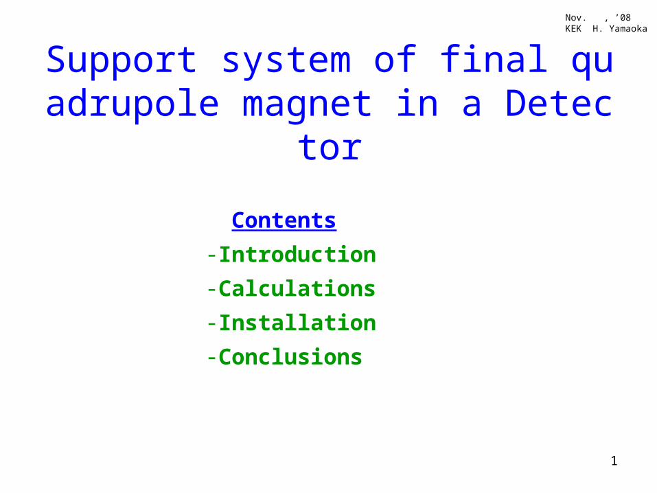
Support system of final quadrupole magnet in a Detector
Contents
-Introduction
-Calculations
-Installation
-Conclusions
Nov. , ’08KEK H. Yamaoka
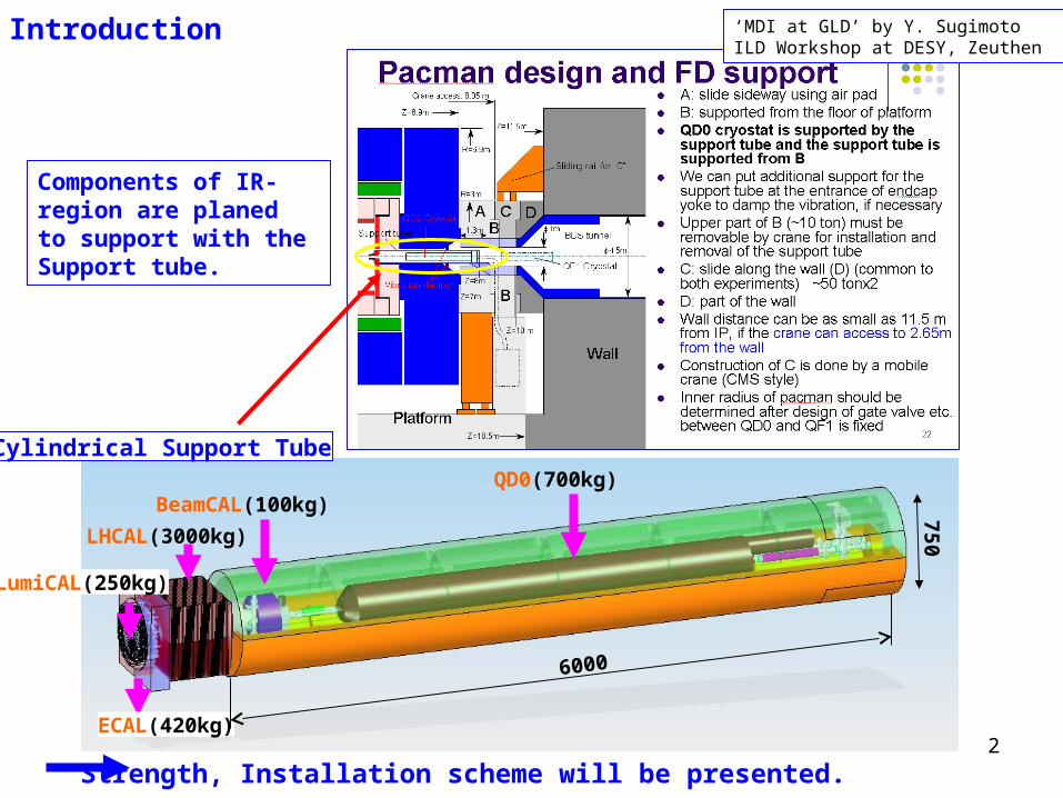
2
QD0(700kg)BeamCAL(100kg)
LHCAL(3000kg)
LumiCAL(250kg)
ECAL(420kg)
6000
750
Cylindrical Support Tube
‘MDI at GLD’ by Y. Sugimoto ILD Workshop at DESY, Zeuthen
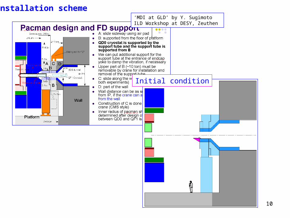
Strength, Installation scheme will be presented.
Components of IR- region are planed to support with the Support tube.
Introduction
3
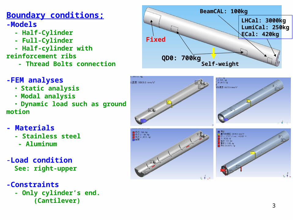
Boundary conditions; -Models - Half-Cylinder - Full-Cylinder - Half-cylinder with reinforcement ribs - Thread Bolts connection
-FEM analyses ・ Static analysis ・ Modal analysis ・ Dynamic load such as ground motion
- Materials - Stainless steel - Aluminum
-Load condition See: right-upper
-Constraints - Only cylinder’s end. (Cantilever)
Fixed
QD0: 700kg
BeamCAL: 100kg
LHCal: 3000kgLumiCal: 250kgECal: 420kg
Self-weight
4
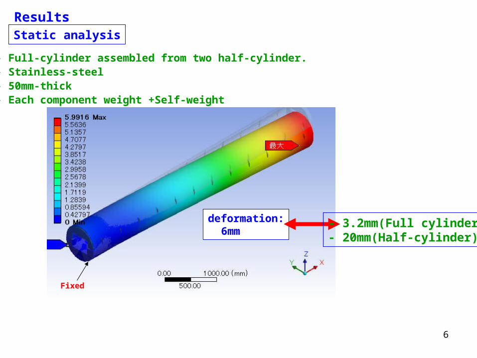
Results
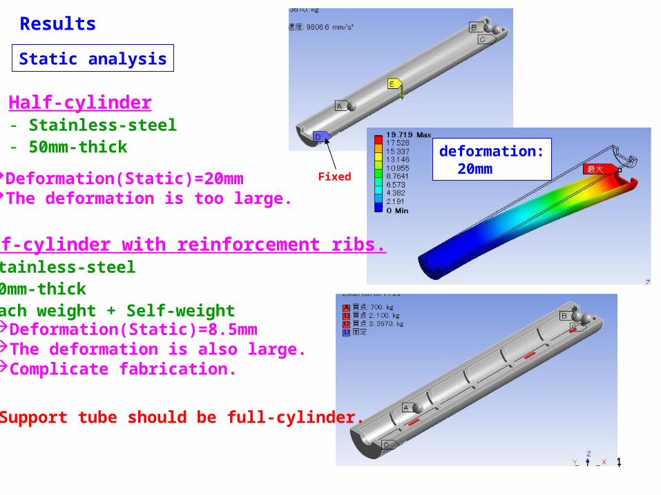
Static analysis
deformation: 20mm
Half-cylinder- Stainless-steel- 50mm-thick
FixedDeformation(Static)=20mmThe deformation is too large.
Half-cylinder with reinforcement ribs.- Stainless-steel- 50mm-thick- Each weight + Self-weightDeformation(Static)=8.5mmThe deformation is also large.Complicate fabrication.
Support tube should be full-cylinder.
5
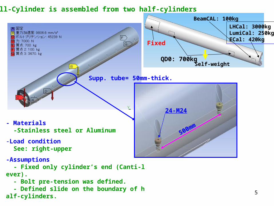
- Materials -Stainless steel or Aluminum
-Load condition See: right-upper
-Assumptions - Fixed only cylinder’s end (Canti-lever). - Bolt pre-tension was defined. - Defined slide on the boundary of half-cylinders.
Fixed
QD0: 700kg
BeamCAL: 100kg
LHCal: 3000kgLumiCal: 250kgECal: 420kg
Self-weight
・ Full-Cylinder is assembled from two half-cylinders
500mm
24-M24
Supp. tube= 50mm-thick.
6
ResultsStatic analysis
deformation: 6mm
- Full-cylinder assembled from two half-cylinder.- Stainless-steel- 50mm-thick- Each component weight +Self-weight
Fixed
- 3.2mm(Full cylinder)- 20mm(Half-cylinder)
7
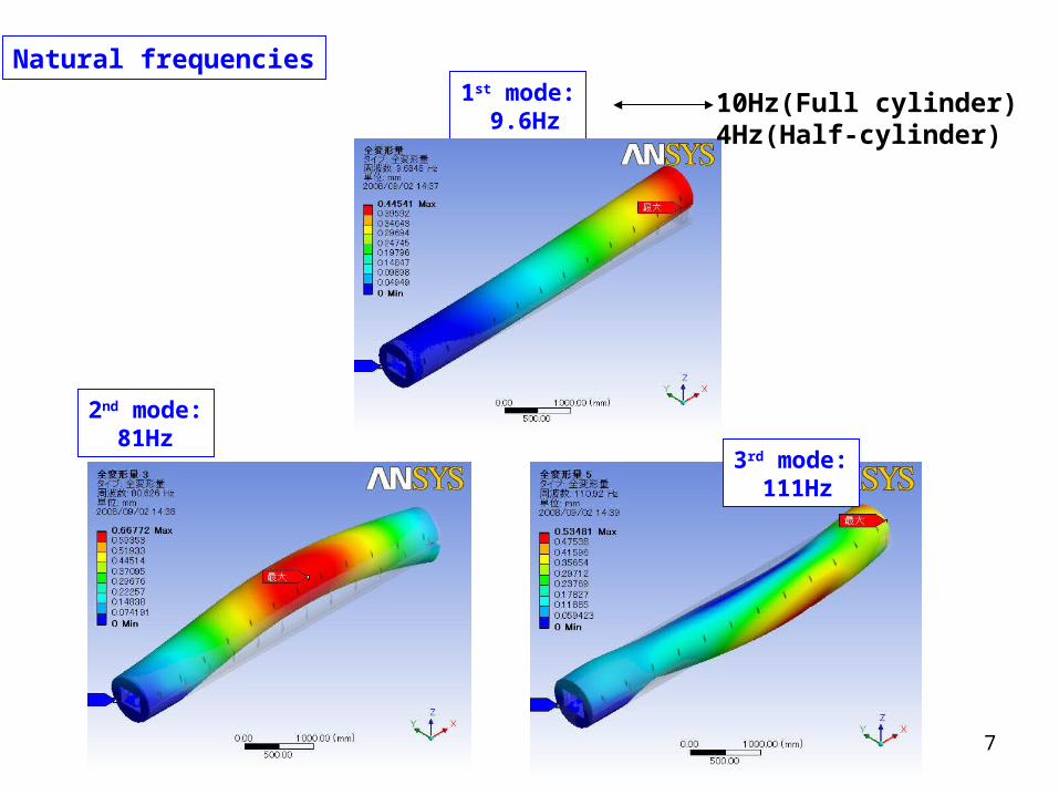
Natural frequencies
2nd mode: 81Hz
3rd mode: 111Hz
1st mode: 9.6Hz
10Hz(Full cylinder)4Hz(Half-cylinder)
8
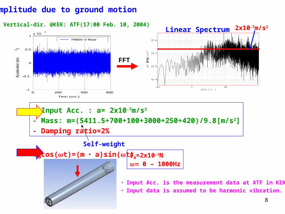
- Input Acc. : a= 2x10⁻⁷m/s2
- Mass: m=(5411.5+700+100+3000+250+420)/9.8[m/s2]
- Damping ratio=2%
F0=2x10⁻³N0 – 1000Hz
Vertical-dir. @KEK: ATF(17:00 Feb. 10, 2004)
(ロ グ周波数0.1 1 10
1E- 6
1E- 7
1E- 8
1E- 9
Linear Spectrum 2x10⁻⁷m/s2
Self-weight
Amplitude due to ground motion
FFT
F0cos(t)=(m ・ a)sin(t)
・ Input Acc. is the measurement data at ATF in KEK.
・ Input data is assumed to be harmonic vibration.
9
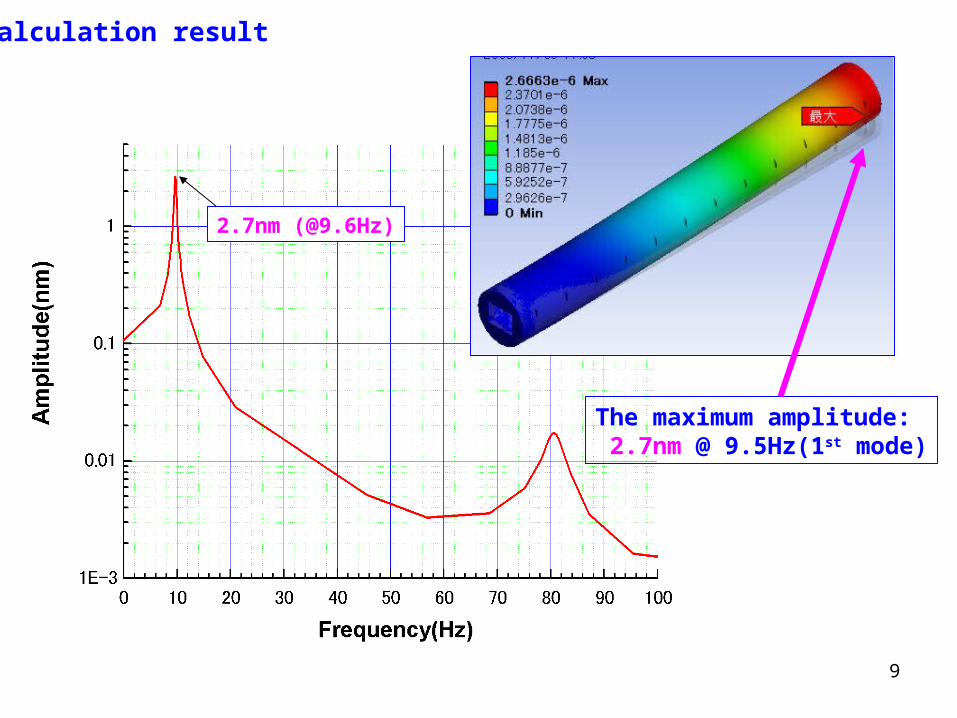
Calculation result
The maximum amplitude: 2.7nm @ 9.5Hz(1st mode)
2.7nm (@9.6Hz)
10
Installation scheme‘MDI at GLD’ by Y. Sugimoto ILD Workshop at DESY, Zeuthen
Initial condition
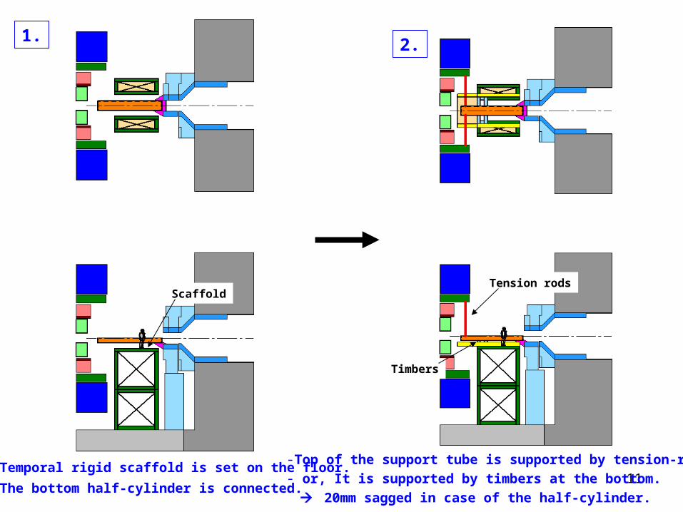
11- Temporal rigid scaffold is set on the floor.
- The bottom half-cylinder is connected.
-Top of the support tube is supported by tension-rods.- or, It is supported by timbers at the bottom.
20mm sagged in case of the half-cylinder.
1. 2.
Tension rodsScaffold
Timbers
12
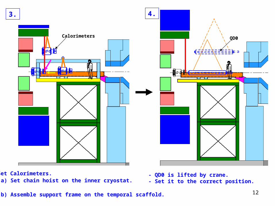
- Set Calorimeters. (a) Set chain hoist on the inner cryostat.or (b) Assemble support frame on the temporal scaffold.
- QD0 is lifted by crane.- Set it to the correct position.
3. 4.
Calorimeters QD0
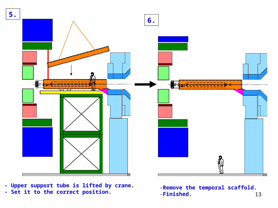
13-Remove the temporal scaffold.-Finished.
5.6.
- Upper support tube is lifted by crane.- Set it to the correct position.
14
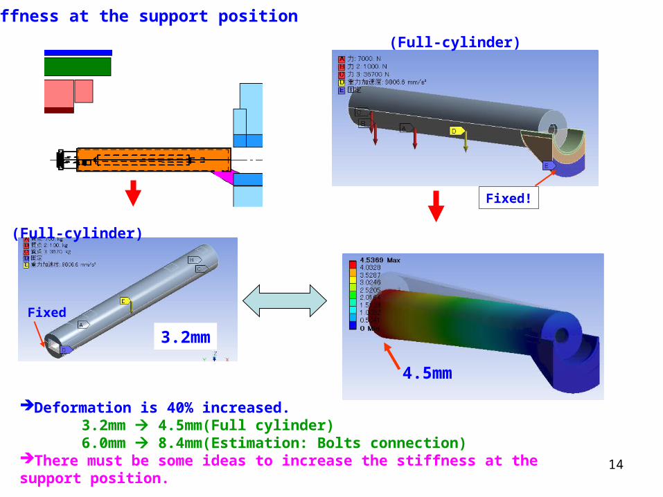
Stiffness at the support position
4.5mm
3.2mm
Fixed
Fixed!
Deformation is 40% increased. 3.2mm 4.5mm(Full cylinder) 6.0mm 8.4mm(Estimation: Bolts connection)There must be some ideas to increase the stiffness at the support position.
(Full-cylinder)
(Full-cylinder)
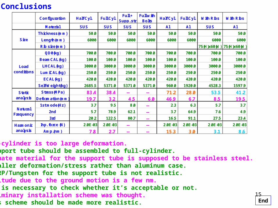
15
Configuration Half Cyl. Full Cyl.Full +
Supp. strFull with
BoltsHalf Cyl. Full Cyl. With Ribs With Ribs
Material SUS SUS SUS SUS Al Al SUS Al
Thickness(mm) 50.0 50.0 50.0 50.0 50.0 50.0 50.0 50.0
Length(mm) 6000 6000 6000 6000 6000 6000 6000 6000
Rib size(mm) 75(H)x60(W) 75(H)x60(W)
QD0(kg) 700.0 700.0 700.0 700.0 700.0 700.0 700.0 700.0
BeamCAL(kg) 100.0 100.0 100.0 100.0 100.0 100.0 100.0 100.0
LHCAL(kg) 3000.0 3000.0 3000.0 3000.0 3000.0 3000.0 3000.0 3000.0
LumiCAL(kg) 250.0 250.0 250.0 250.0 250.0 250.0 250.0 250.0
ECAL(kg) 420.0 420.0 420.0 420.0 420.0 420.0 420.0 420.0
Self-Weight(kg) 2685.5 5371.0 5371.0 5371.0 960.0 1920.0 4528.3 1597.9
Stress(MPa) 83.4 38.4 -- -- 71.2 28.0 53.5 41.2Deformation(mm) 19.7 3.2 4.5 6.0 46.9 6.7 8.5 19.5
1st mode(Hz) 3.7 9.5 8.0 -- 2.3 6.3 5.7 3.7
2nd 5.7 78.9 62.1 -- 3.7 64.9 7.6 4.9
3rd 20.2 122.5 80.7 -- 16.5 91.1 27.5 23.4
Inp. force (N) 2.0E-03 2.0E-03 -- -- 2.0E-03 2.0E-03 2.0E-03 2.0E-03
Amp.(nm) 7.8 2.7 -- -- 15.3 3.0 3.1 8.6
Size
Harmonicanalysis
Loadconditions
Staticanalysis
NaturalFrequency
Conclusions
- Half-cylinder is too large deformation. Support tube should be assembled to full-cylinder. - Adequate material for the support tube is supposed to be stainless steel. Smaller deformation/stress rather than aluminum case. CFRP/Tungsten for the support tube is not realistic.- Amplitude due to the ground motion is a few nm. It is necessary to check whether it’s acceptable or not.- Preliminary installation scheme was thought. This scheme should be made more realistic. End