Embed Size (px)
Citation preview

Main Beam Quadrupole SupportFriedrich Lackner
(TS-SU)
CLIC08 Workshop
2
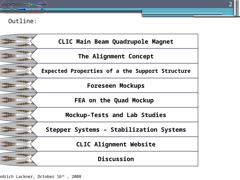
CLIC Main Beam Quadrupole Magnet
The Alignment Concept
Expected Properties of a the Support Structure
Foreseen Mockups
FEA on the Quad Mockup
Mockup-Tests and Lab Studies
Stepper Systems – Stabilization Systems
CLIC Alignment Website
Discussion
Outline:
Friedrich Lackner, October 16th , 2008
3
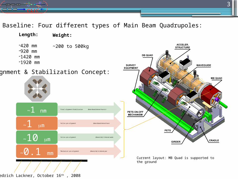
Baseline: Four different types of Main Beam Quadrupoles:
Length:
-420 mm -920 mm-1420 mm-1920 mm
Weight:
~200 to 500kg
Current layout: MB Quad is supported to the ground
~1 nm•Final alignment/Stabilization (Beam Based) Interval: hours & <
~1 mm •Active pre-alignment (Beam Based) Interval: hours
~10 mm•Active pre-alignment (Movers) Dof.: 5; Interval: weeks
~0.1 mm•Mechanical pre-alignment (Movers) Dof.: 6; Interval: year
Alignment & Stabilization Concept:
Friedrich Lackner, October 16th , 2008
4
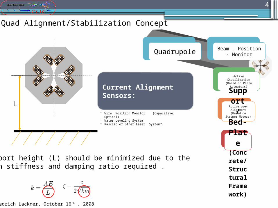
Quadrupole Beam - Position - Monitor
Active Stabilization(Based on Piezo
Actuators)
Active pre-Alignment(Based on
Stepper Motors)
Support
/ Bed
-Plat
e(Concrete
/Structural Framewor
k)
L
Support height (L) should be minimized due to thehigh stiffness and damping ratio required .
Current Alignment Sensors:
• Wire Position Monitor (Capacitive, Optical)• Water Leveling System• Rasclic or other Laser System?
MB-Quad Alignment/Stabilization Concept
Friedrich Lackner, October 16th , 2008

5
Expected Properties of a CLIC Mainbeam Quadrupole Support
Installation
Weight (optimized)
Compact Design
Easy to Transport
Easy to Align
Easy to re-Adjust
Installation Time (low)
Cost-Efficient
Operation
Damping Ratio (high)Stiffness Characteristics
(excellent)Availability (high during entire life
cycle) Temperature (low sensitivity)
Humidity (low sensitivity)
Radiation (high resistance)
Magnetic field (high resistance)
Friedrich Lackner, October 16th , 2008
Requires mockup studies to find best solution

6
Nominal gradient 200.1 T/mNominal integrated gradient 370.0 Tm/mAperture radius 5.0 mmIron length 1844.0 mmEffective length 1849.0 mmTotal magnet weight 393.3 kgTotal magnet length 1914.7 mmTotal magnet width 192.0 mmTotal magnet height 192.0 mm
Conductor height 5.6 mmConductor width 5.6 mmCooling hole diameter 3.6 mmTotal number of turns 16
Number of cooling circuits per coil 1.0Pressure drop 4 bar
Current density 6.59 A/mm2 Temperature rise 22.3 KCoolant velocity 1.1 m/sTotal cooling flow 2.6 l/min
Nominal current 140 A
Magnet resistance (hot) 201.0 mOhmPower consumption 4108.5 WTotal stored energy 420.7 kJ Inductance 42.9 mHVoltage drop (R*I) 29.3 V
Coil
Cooling
Electrical parameters
CLIC Main Linac Quadrupole (V4e)
Magnet
Magnet Mockup Design: Thomas Zickler (CERN)
Quadrupole Mockup (Length = 1920mm)
Most complicate version will be studied based on a mockup:
Preliminary Mockup based on a T-shaped Profile will be studied based on a layered assembly and as a solid.
Layered Profiles will be based on Electromagnetic steel (e.g. Stabolit 70 – Thyssen Krupp)
Friedrich Lackner, October 16th , 2008

7
Quadrupole mockup simulation results:
Modal analysis and self weight deformation studied using different support positions
Quadrupole support in Gaussian points results in a deformation on self load of: 1.1um
Simulation with ANSYS WBand ANSYS Classic
Solid45 elements & Structural Steel
(Mockup simulation without coil)
Structural Steel; Mass: 333.45 kg
Friedrich Lackner, October 16th , 2008
Supporting points

8
Previous tests (S. Redaelli, CERN):
Main focus in the 90th was given in the vertical stabilization of the quadrupole magnet
5 Stepper motors were used to align the support to 5 DOF
Supports were joints and bearings with low friction
Friedrich Lackner, October 16th , 2008
Mockup-Tests and Lab Studies
Change of requirements in pre-alignment and especially higher loads requires complete redevelopment. Furthermore documentation regarding reachable Repeatability, Accuracy and Resolution in the 5 DOF of the former System undiscoverable.
Behavior of Stepper System can be studied by using the old setup as occasionally mockup

9
CTF2 Stepper System reactivated:
Foreseen steps: - Implementation of feedback loop- Redesign of critical parts (guiding)
Frictionless Operation Possible?
New software version still communicates with the old setup…
First operations… Friedrich Lackner, October 16th , 2008

10
•Modal measurement for CTF2 stepper motor planned within the next weeks.
• Will provide important information for the stiffness of the entire support system.
Many sources for improvements
CTF2 Alignment Concept studied using the FEM
Friedrich Lackner, October 16th , 2008
What to learn from an old Setup?
• Important information of friction and clearance behavior• Repeatability of important
alignment parameters
• Important input for ANSYS and for all further studies Will help to select adequate movers for
CLICAlso answers the question -> Frictionless pre-alignment required?

11
Regarding Movers:
Market research on suppliers for stepper motor development and “frictionless” joints
Main issue: Insufficient load capacity -> most μ movers and hexapods on the market can adjust loads up to max. 40kg
- PI- Karlsruhe (D)
- ZTS -VVU – Kosice (Sk): Stepper system supplier for LHC low beta magnets
- Midi ingenierie – Labege (F): Stepper system supplier for CTF2
E.g.: PI MIKE M-238 unidirectional repeatability: 0.3 μm, max. load: 40kg
Further development of the M-238 for a load of 100kg -> 15000 CHF/Piece and complete new design for loads up to 200kg

12
Progress on research for the nano stabilization of the MB-quad:
Further possibilities using piezo stacks are studied
Guiding Flexures: Available solutions are not able to provide required load capacity
Foreseen: Production of a guiding flexure at CERN using wire -electro discharge machining is foreseen.
Friedrich Lackner, October 16th , 2008
Nano membran -> studied by Kurt Artoos et al. (TS-MME)
Critical: Implementation and fixation of the piezo actuator

13
Frictionless support ‘guiding flexure’
Piezo Force
Sketch: Layout using four guiding flexures
Friedrich Lackner, October 16th , 2008

14
Vertical space to integrate a stabilization
system is limited by 100 mm
(between MQ and the girder)
How to implement ?
600 mm
482
mm
100
mm
Girder:150*320mm
94 m
m
Remark: nm
stabilization
requires a minimum vertical
distance.
Space limitations on current Module design:
Friedrich Lackner, October 16th , 2008

15
Friedrich Lackner, October 16th , 2008
Frictionless operation of the pre-alignment system by applying linear elastic deformation?
How to provide optimal stiffness characteristics for the stabilization system on beam level?
Decoupling between pre-alignment and stabilization system.
Many solutions, proposals and open work -> still there are so many more open questions to be studied, e.g.:

16
Friedrich Lackner, October 16th , 2008
Z
X
Y
Idea: Increasing the stiffness for a stabilization system by clamping the pre-alignment system to concrete support (applying clamping force in non critical Z direction).
Proposal for Mockup studies:
Stabilization System
Concrete
Pre-alignment system

17
http://clic-alignment.web.cern.ch/clic-alignment/
Friedrich Lackner, October 16th , 2008

18
CLIC Main Beam Quadrupole Magnet
The Alignment Concept
Expected Properties of a the Support Structure
Foreseen Mockups
FEA on Quad Mockup
Mockup-Tests and Lab Studies
Stepper Systems – Stabilization Systems
CLIC Alignment Website
Discussion
Outline:
Friedrich Lackner, October 16th , 2008