Embed Size (px)
Citation preview

Page 1 1999 Lennox Industries Inc.
Corp. 9710−L7
Service Literature
SURELIGHT IGNITION SYSTEM
Revised 9−2003
SURELIGHT and BASIC SURELIGHT IGNITION SYSTEM
I−GENERALThe SureLight� and Basic SureLight ignition system con�
sists of a Lennox control board (figure1) and hot surface
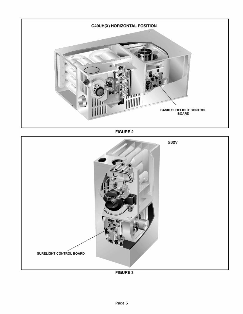
ignitor . Figures 2 and 3 show the general location of the
control board in multi and downflow position units. See
table 2 for furnace model / igntion system matchup. Both
models are similar except the SureLight board has a desig�
nated continuous blower speed and is protected by a
circuit breaker located on the control box. Terminal desig�
nations are shown in table 3. The Basic SureLight board
will energize HEAT−H heating speed for continuous blower
and the control circuit is protected by an on board fuse. On
both models the board and ignitor work in combination to
ensure furnace ignition and ignitor durability. Both models
control all major furnace operations. Tables 4 and 5 (Sur�
elight) and tables 6 and 7 (Basic Surelight) show jack plug
terminal designations. Both boards also feature two LED
lights for trouble shooting (see table 1 for diagnostic codes)
and two accessory terminals. Terminal ACC energizes
with the indoor blower on the SureLight board and terminal
EAC−H energizes with the indoor blower on the Basic Sur�
elight. Terminal HTG ACC energizes when CAI is
energized on the SureLight board and terminal HUM−N en�
ergizes with CAI on the Basic SureLight board. The
SureLight board has a built in heating isolation relay. See
wiring diagram for heat anticipator settings.
The ignitor used for both models is made of durable silicon−
nitride. Ignitor longevity is also enhanced by controlling the
temperature of the ignitor. The board finds the lowest ignitor
temperature which will successfully light the burner, thus in�
creasing the life of the ignitor.
IMPORTANTIgnition control will not operate unless unit isproperly grounded. 120V supply must beinstalled with correct polarity.
CAUTION
Electrostatic discharge can affect electroniccomponents. Take precautions during furnaceinstallation and service to protect the furnace’selectronic controls. Precautions will help toavoid control exposure to electrostatic dis�charge by putting the furnace, the control andthe technician at the same electrostatic poten�tial. Neutralize electrostatic charge by touchinghand and all tools on an unpainted unit surface,such as the gas valve or blower deck, before per�forming any service procedure.
ELECTROSTATIC DISCHARGE (ESD)
Precautions and Procedures
Table of Contents
I General Information 1. . . . . . . . . . . . . . . . . . . . . . . . .
Board Diagnostic Codes 2. . . . . . . . . . . . . . . . . . . . . . .
Board Terminal Designations 3. . . . . . . . . . . . . . . . . . .
II Operation 6. . . . . . . . . . . . . . . . . . . . . . . . . . . . . . . . . .
III Furnace Wiring and Operation Sequence 8. . . . . .
G23 8. . . . . . . . . . . . . . . . . . . . . . . . . . . . . . . . . . . . .
80MGF 9. . . . . . . . . . . . . . . . . . . . . . . . . . . . . . . . . . .
G26 10. . . . . . . . . . . . . . . . . . . . . . . . . . . . . . . . . . . . .
GHR26 11. . . . . . . . . . . . . . . . . . . . . . . . . . . . . . . . . . .
G24M 12. . . . . . . . . . . . . . . . . . . . . . . . . . . . . . . . . . . .
G40UH 13. . . . . . . . . . . . . . . . . . . . . . . . . . . . . . . . . . .
G50UH 14. . . . . . . . . . . . . . . . . . . . . . . . . . . . . . . . . . .
80UHG 15. . . . . . . . . . . . . . . . . . . . . . . . . . . . . . . . . . .
90UGF 16. . . . . . . . . . . . . . . . . . . . . . . . . . . . . . . . . . .
G27M 17. . . . . . . . . . . . . . . . . . . . . . . . . . . . . . . . . . . .
G32 18. . . . . . . . . . . . . . . . . . . . . . . . . . . . . . . . . . . . .
G32V 19. . . . . . . . . . . . . . . . . . . . . . . . . . . . . . . . . . . .
GHR32 20. . . . . . . . . . . . . . . . . . . . . . . . . . . . . . . . . . .
GHR32V 21. . . . . . . . . . . . . . . . . . . . . . . . . . . . . . . . .
Operation Sequence Flow Chart 23. . . . . . . . . . . . . . . .
SureLight Board 23. . . . . . . . . . . . . . . . . . . . . . . . . . .
Basic SureLight Board 28. . . . . . . . . . . . . . . . . . . . . .
Troubleshooting Guide (both models) 32. . . . . . . . . . .
Page 2
SURELIGHT INTEGRATED CONTROL BOARD
FIGURE 1
J58
J156
XFMR−N
BASIC SURELIGHT INTEGRATED CONTROL BOARD
BOARD # 63K8901, 24L8501, 56L8301 and 97L4801BOARD # 12L6901 and 56L8401
Both model boards are equipped with two LED lights for troubleshooting. The diagnostic codes are listed below in table 1.
TABLE 1
DIAGNOSTIC CODESMAKE SURE TO ID LED’S CORRECTLY: REFER TO INSTALLATION INSTRUCTIONS FOR CONTROL BOARD LAYOUT.
LED #1 LED #2 DESCRIPTIONSIMULTANEOUS
SLOW FLASHSIMULTANEOUS
SLOW FLASHPower − Normal operation
Also signaled during cooling and continuous fan.
SIMULTANEOUS FASTFLASH
SIMULTANEOUS FASTFLASH
Normal operation − signaled when heating demand initiated at thermostat.
SLOW FLASH ON
Primary or Secondary limit open. Units with board 63K8901 or 24L8501 (Sur�eLight) and units with board 12L6901 (Basic SureLight): Limit must close within 5trials for ignition or board goes into one hour limit Watchguard. Units with board
56L8301, 97L48 (SureLight) and 56L8401 and 10M9301 (Basic SureLight): Limitmust close within 3 minutes or board goes into one hour limit Watchguard.
OFF SLOW FLASH
Pressure switch open or has opened 5 times during a single call for heat; OR:Blocked inlet/exhaust vent; OR: Condensate line blocked; OR: Pressure switch
closed prior to activation of combustion air blower.
ALTERNATING SLOWFLASH
ALTERNATING SLOWFLASH
Watchguard − burners fail to ignite.
SLOW FLASH OFF Flame sensed without gas valve energized.
ON SLOW FLASHRollout switch open. OR: 9 pin (SureLight) or 12 pin (Basic SureLight) connector
improperly attached.
ONONOFF
ONOFFON
Circuit board failure or control wired incorrectly.
FAST FLASH SLOW FLASH Main power polarity reversed. Switch line and neutral.
SLOW FLASH FAST FLASH Low flame signal (see note below). Replace flame sense rod.
ALTERNATING FASTFLASH
ALTERNATING FASTFLASH
Improper main ground or line voltage below 75 volts; OR: Broken ignitor; OR:Open ignitor circuit.
NOTE − Slow flash equals 1 Hz (one flash per second). Fast flash equals 3 Hz (three flashes per second). Normal flame signal for SureLight control is 0.61
or greater microamps with a drop out signal of 0.20 or less microamps. Normal flame signal for Basic SureLight is 0.18 or greater micro amps with a dropout signal of 0.15 or less micramps.
Page 3
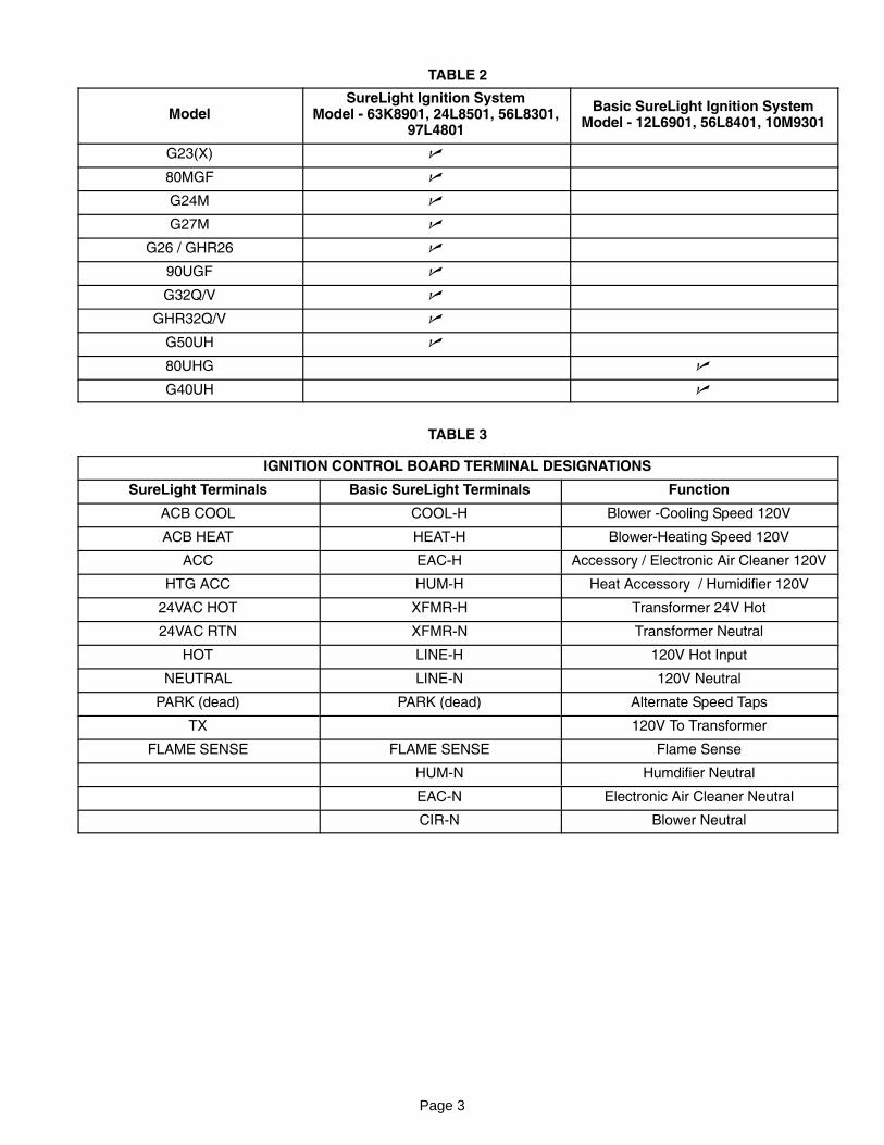
TABLE 2
ModelSureLight Ignition System
Model − 63K8901, 24L8501, 56L8301,97L4801
Basic SureLight Ignition SystemModel − 12L6901, 56L8401, 10M9301
G23(X) �
80MGF �
G24M �
G27M �
G26 / GHR26 �
90UGF �
G32Q/V �
GHR32Q/V �
G50UH �
80UHG �
G40UH �
TABLE 3
IGNITION CONTROL BOARD TERMINAL DESIGNATIONS
SureLight Terminals Basic SureLight Terminals Function
ACB COOL COOL−H Blower −Cooling Speed 120V
ACB HEAT HEAT−H Blower−Heating Speed 120V
ACC EAC−H Accessory / Electronic Air Cleaner 120V
HTG ACC HUM−H Heat Accessory / Humidifier 120V
24VAC HOT XFMR−H Transformer 24V Hot
24VAC RTN XFMR−N Transformer Neutral
HOT LINE−H 120V Hot Input
NEUTRAL LINE−N 120V Neutral
PARK (dead) PARK (dead) Alternate Speed Taps
TX 120V To Transformer
FLAME SENSE FLAME SENSE Flame Sense
HUM−N Humdifier Neutral
EAC−N Electronic Air Cleaner Neutral
CIR−N Blower Neutral
Page 4
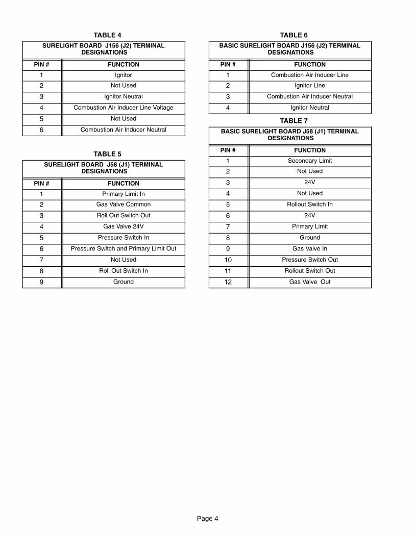
TABLE 4
SURELIGHT BOARD J156 (J2) TERMINAL DESIGNATIONS
PIN # FUNCTION
1 Ignitor
2 Not Used
3 Ignitor Neutral
4 Combustion Air Inducer Line Voltage
5 Not Used
6 Combustion Air Inducer Neutral
TABLE 5
SURELIGHT BOARD J58 (J1) TERMINAL DESIGNATIONS
PIN # FUNCTION
1 Primary Limit In
2 Gas Valve Common
3 Roll Out Switch Out
4 Gas Valve 24V
5 Pressure Switch In
6 Pressure Switch and Primary Limit Out
7 Not Used
8 Roll Out Switch In
9 Ground
TABLE 6
BASIC SURELIGHT BOARD J156 (J2) TERMINAL DESIGNATIONS
PIN # FUNCTION
1 Combustion Air Inducer Line
2 Ignitor Line
3 Combustion Air Inducer Neutral
4 Ignitor Neutral
TABLE 7
BASIC SURELIGHT BOARD J58 (J1) TERMINAL DESIGNATIONS
PIN # FUNCTION
1 Secondary Limit
2 Not Used
3 24V
4 Not Used
5 Rollout Switch In
6 24V
7 Primary Limit
8 Ground
9 Gas Valve In
10 Pressure Switch Out
11 Rollout Switch Out
12 Gas Valve Out
Page 5
FIGURE 2
G40UH(X) HORIZONTAL POSITION
BASIC SURELIGHT CONTROLBOARD
FIGURE 3
G32V
SURELIGHT CONTROL BOARD
Page 6
II−OPERATION (Both Models)
FAN TIMER CONTROL
The fan on time (during heat mode) of 45 seconds is notadjustable. Fan off time (time that the blower operates after
the heat demand has been satisfied) can be adjusted by
flipping the dip switches located on the SureLight inte�grated control. The unit is shipped with a factory fan off
setting of 90 seconds. Fan off time will affect comfort and is
adjustable to satisfy individual applications. There is nofan−on or fan−off time during cool mode. Fan energizes
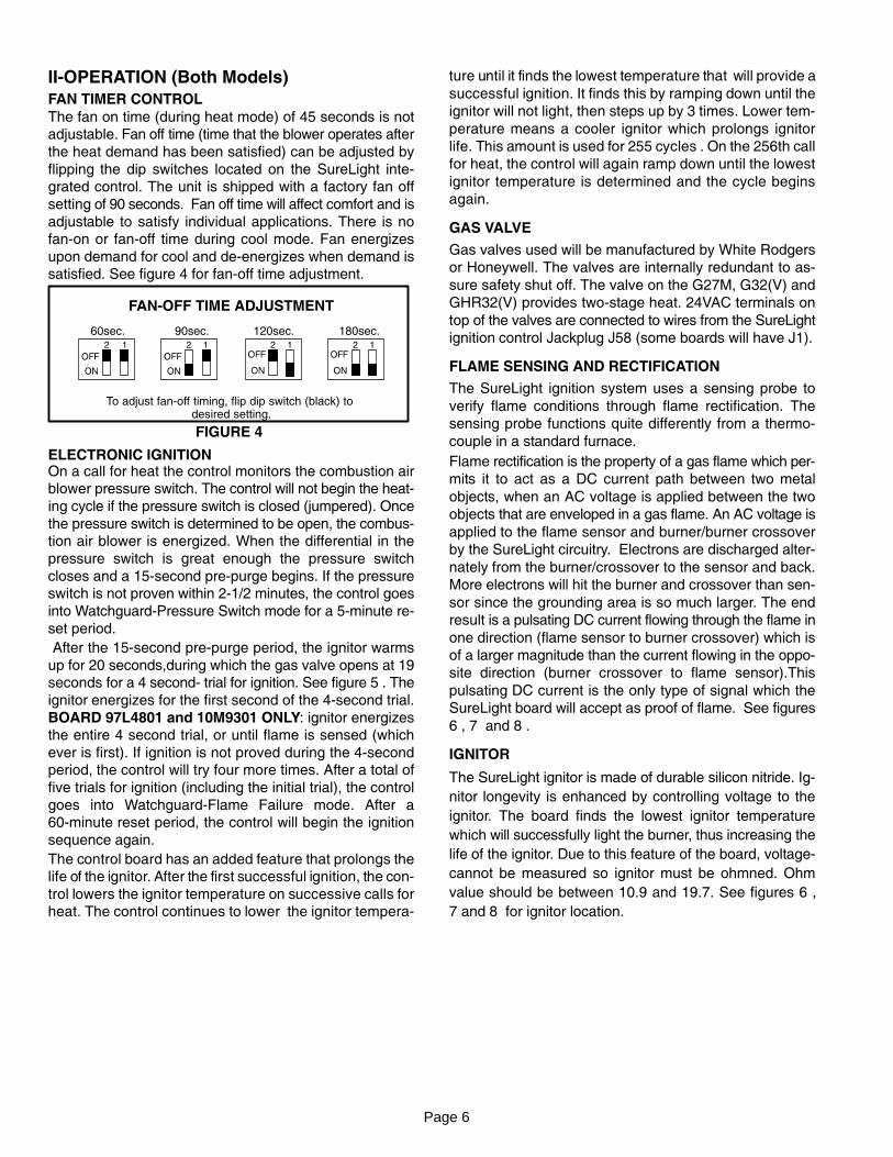
upon demand for cool and de−energizes when demand issatisfied. See figure 4 for fan−off time adjustment.
FIGURE 4
FAN�OFF TIME ADJUSTMENT
To adjust fan−off timing, flip dip switch (black) to desired setting.
60sec. 90sec. 120sec. 180sec.
ELECTRONIC IGNITIONOn a call for heat the control monitors the combustion airblower pressure switch. The control will not begin the heat�
ing cycle if the pressure switch is closed (jumpered). Once
the pressure switch is determined to be open, the combus�tion air blower is energized. When the differential in the
pressure switch is great enough the pressure switch
closes and a 15−second pre−purge begins. If the pressureswitch is not proven within 2−1/2 minutes, the control goes
into Watchguard−Pressure Switch mode for a 5−minute re−
set period.
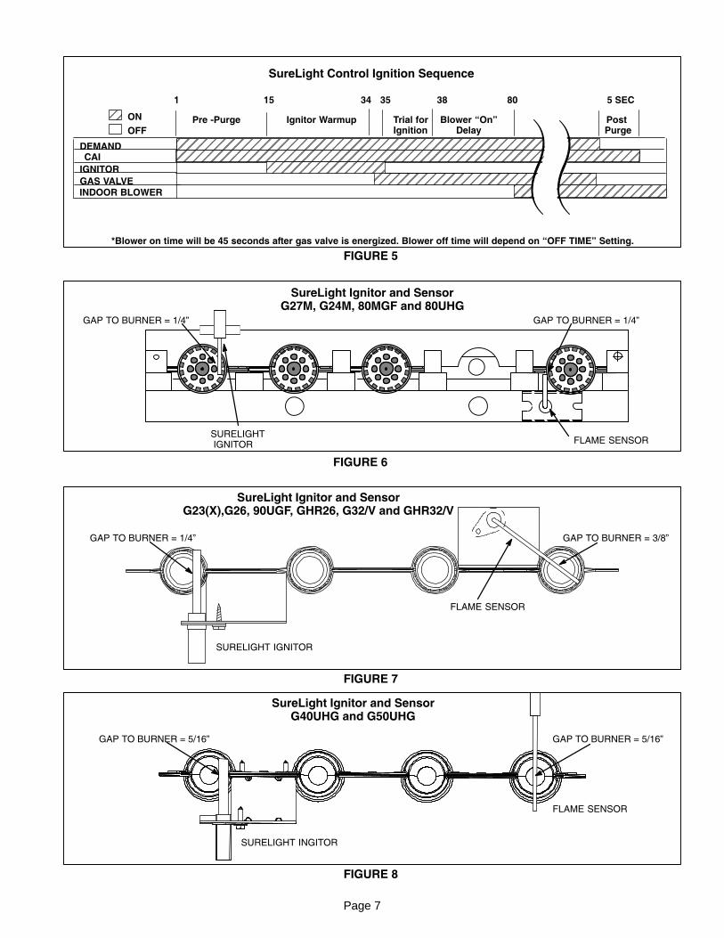
After the 15−second pre−purge period, the ignitor warms
up for 20 seconds,during which the gas valve opens at 19seconds for a 4 second− trial for ignition. See figure 5 . The
ignitor energizes for the first second of the 4−second trial.
BOARD 97L4801 and 10M9301 ONLY: ignitor energizesthe entire 4 second trial, or until flame is sensed (which
ever is first). If ignition is not proved during the 4−secondperiod, the control will try four more times. After a total of
five trials for ignition (including the initial trial), the control
goes into Watchguard−Flame Failure mode. After a60−minute reset period, the control will begin the ignition
sequence again.
The control board has an added feature that prolongs thelife of the ignitor. After the first successful ignition, the con�
trol lowers the ignitor temperature on successive calls forheat. The control continues to lower the ignitor tempera�
ture until it finds the lowest temperature that will provide a
successful ignition. It finds this by ramping down until the
ignitor will not light, then steps up by 3 times. Lower tem�
perature means a cooler ignitor which prolongs ignitor
life. This amount is used for 255 cycles . On the 256th call
for heat, the control will again ramp down until the lowest
ignitor temperature is determined and the cycle begins
again.
GAS VALVE
Gas valves used will be manufactured by White Rodgers
or Honeywell. The valves are internally redundant to as�
sure safety shut off. The valve on the G27M, G32(V) and
GHR32(V) provides two−stage heat. 24VAC terminals on
top of the valves are connected to wires from the SureLight
ignition control Jackplug J58 (some boards will have J1).
FLAME SENSING AND RECTIFICATION
The SureLight ignition system uses a sensing probe to
verify flame conditions through flame rectification. The
sensing probe functions quite differently from a thermo�
couple in a standard furnace.
Flame rectification is the property of a gas flame which per�
mits it to act as a DC current path between two metal
objects, when an AC voltage is applied between the two
objects that are enveloped in a gas flame. An AC voltage is
applied to the flame sensor and burner/burner crossover
by the SureLight circuitry. Electrons are discharged alter�
nately from the burner/crossover to the sensor and back.
More electrons will hit the burner and crossover than sen�
sor since the grounding area is so much larger. The end
result is a pulsating DC current flowing through the flame in
one direction (flame sensor to burner crossover) which is
of a larger magnitude than the current flowing in the oppo�
site direction (burner crossover to flame sensor).This
pulsating DC current is the only type of signal which the
SureLight board will accept as proof of flame. See figures
6 , 7 and 8 .
IGNITOR
The SureLight ignitor is made of durable silicon nitride. Ig�
nitor longevity is enhanced by controlling voltage to the
ignitor. The board finds the lowest ignitor temperature
which will successfully light the burner, thus increasing the
life of the ignitor. Due to this feature of the board, voltage�
cannot be measured so ignitor must be ohmned. Ohm
value should be between 10.9 and 19.7. See figures 6 ,
7 and 8 for ignitor location.
Page 7
ÉÉÉÉÉÉÉÉÉÉÉÉÉÉÉÉÉÉÉÉÉÉÉÉÉÉÉÉÉÉÉÉÉÉÉÉÉÉÉÉÉÉÉÉÉÉÉÉ
ÉÉÉÉÉÉÉÉÉÉÉÉÉÉÉÉÉÉÉÉÉÉÉÉÉÉ
ÉDEMANDCAI
GAS VALVE
15
ON
OFF
ÉÉÉÉÉÉÉÉÉÉÉÉÉÉÉÉÉÉÉÉÉÉÉÉÉÉÉ
ÉÉ
38
ÉÉÉÉÉÉÉÉÉÉÉÉÉÉÉÉ
IGNITOR
341
Pre −Purge Ignitor Warmup Trial forIgnition
Post Purge
5 SEC80
*Blower on time will be 45 seconds after gas valve is energized. Blower off time will depend on �OFF TIME" Setting.
INDOOR BLOWER ÉÉÉÉÉÉÉÉÉ
FIGURE 5
Blower �On"Delay
SureLight Control Ignition Sequence
35
FLAME SENSORSURELIGHT IGNITOR
SureLight Ignitor and SensorG27M, G24M, 80MGF and 80UHG
FIGURE 6
GAP TO BURNER = 1/4" GAP TO BURNER = 1/4"
SURELIGHT IGNITOR
FLAME SENSOR
SureLight Ignitor and SensorG23(X),G26, 90UGF, GHR26, G32/V and GHR32/V
FIGURE 7
GAP TO BURNER = 1/4" GAP TO BURNER = 3/8"
SureLight Ignitor and SensorG40UHG and G50UHG
FIGURE 8
SURELIGHT INGITOR
FLAME SENSOR
GAP TO BURNER = 5/16" GAP TO BURNER = 5/16"
Page 8
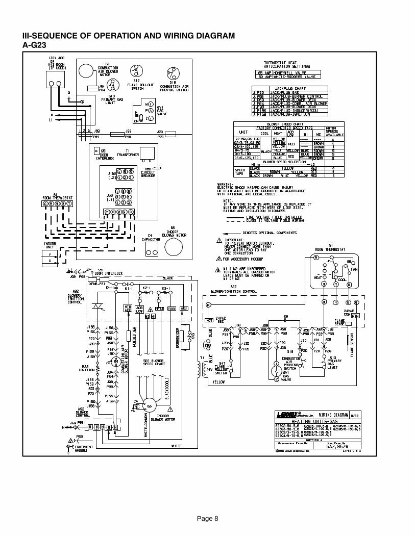
III−SEQUENCE OF OPERATION AND WIRING DIAGRAMA−G23
Page 9
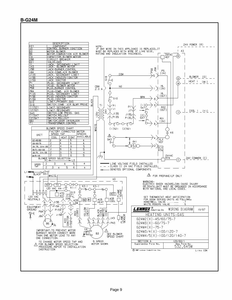
B−G24M
Page 10
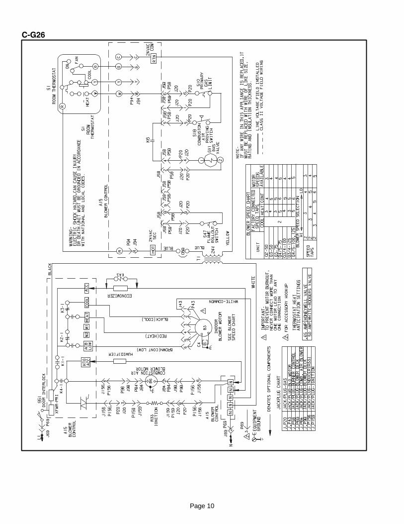
C−G26
Page 11
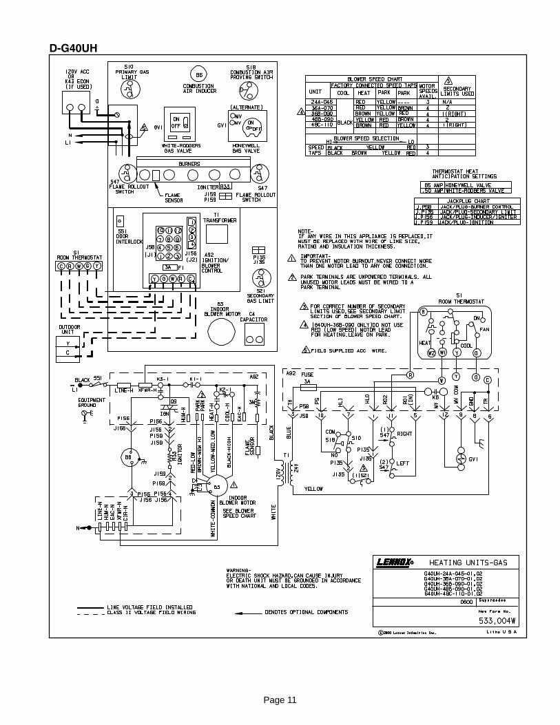
D−G40UH
Page 12
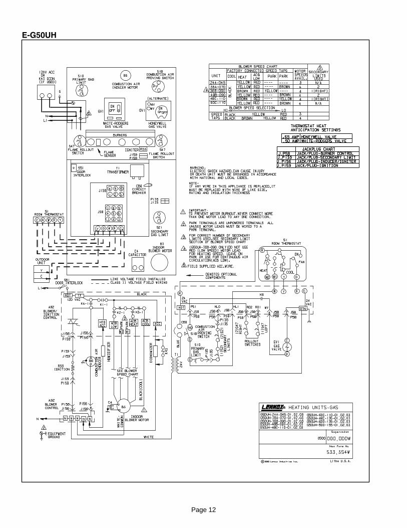
E−G50UH
Page 13
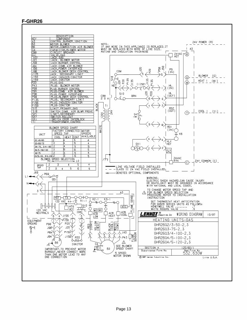
F−GHR26
Page 14
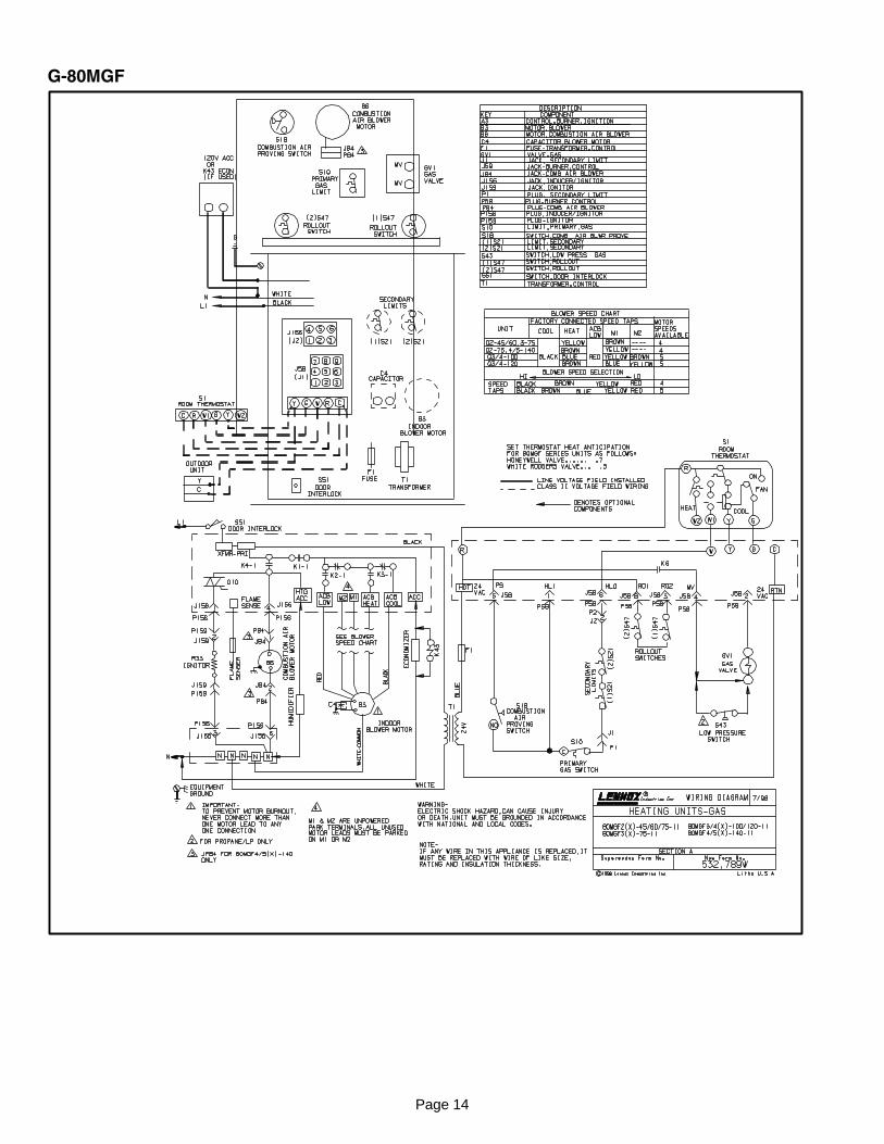
G−80MGF
Page 15
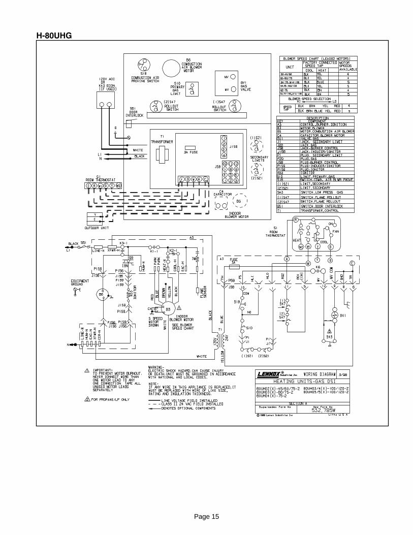
H−80UHG
Page 16
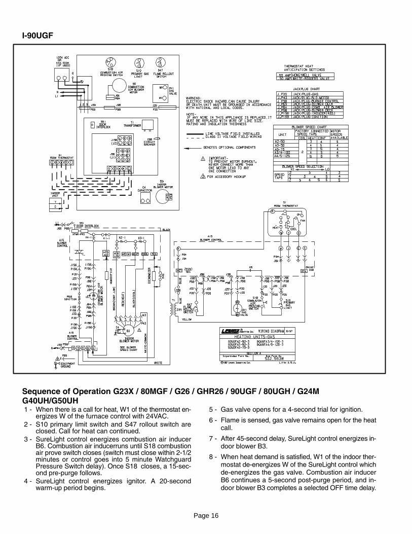
I−90UGF
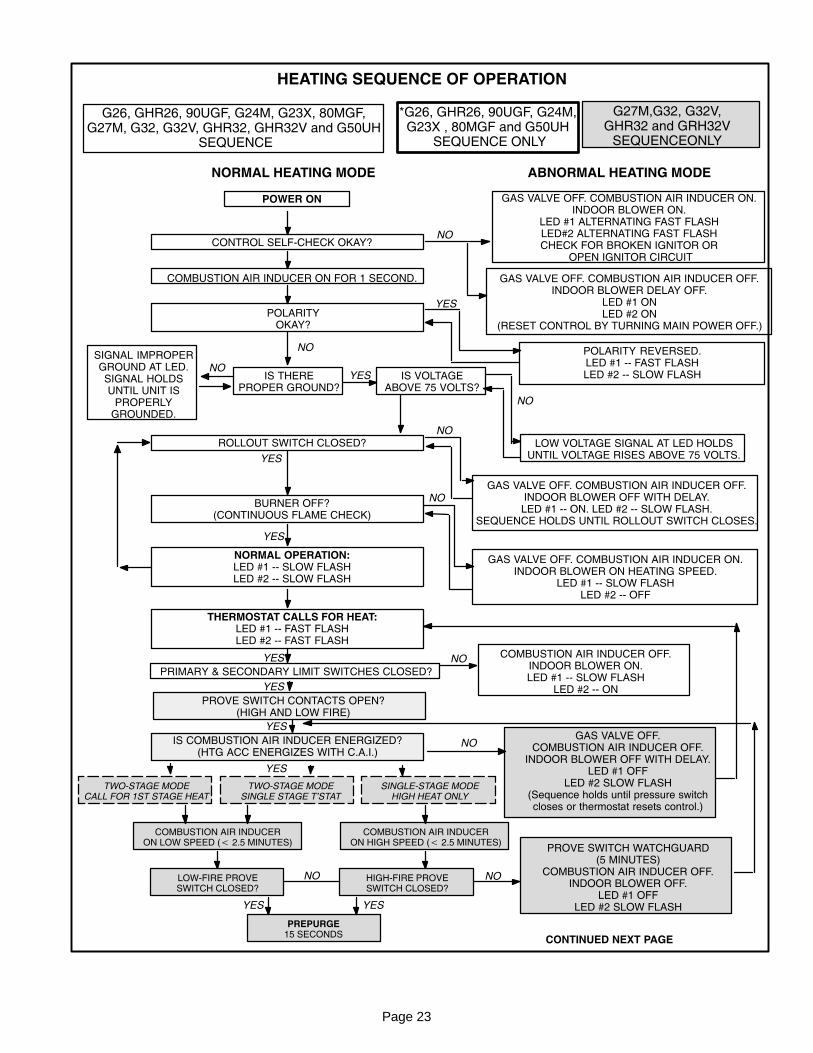
Sequence of Operation G23X / 80MGF / G26 / GHR26 / 90UGF / 80UGH / G24MG40UH/G50UH 1 − When there is a call for heat, W1 of the thermostat en�
ergizes W of the furnace control with 24VAC.
2 − S10 primary limit switch and S47 rollout switch areclosed. Call for heat can continued.
3 − SureLight control energizes combustion air inducerB6. Combustion air inducerruns until S18 combustionair prove switch closes (switch must close within 2−1/2minutes or control goes into 5 minute WatchguardPressure Switch delay). Once S18 closes, a 15−sec�ond pre−purge follows.
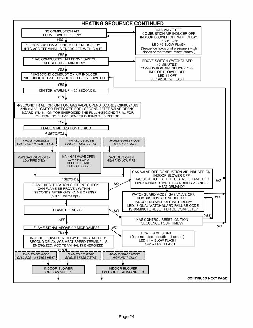
4 − SureLight control energizes ignitor. A 20−secondwarm−up period begins.
5 − Gas valve opens for a 4−second trial for ignition.
6 − Flame is sensed, gas valve remains open for the heatcall.
7 − After 45−second delay, SureLight control energizes in�door blower B3.
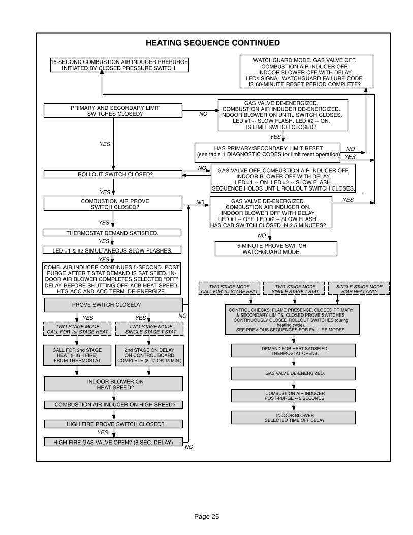
8 − When heat demand is satisfied, W1 of the indoor ther�mostat de−energizes W of the SureLight control whichde−energizes the gas valve. Combustion air inducerB6 continues a 5−second post−purge period, and in�door blower B3 completes a selected OFF time delay.
Page 17
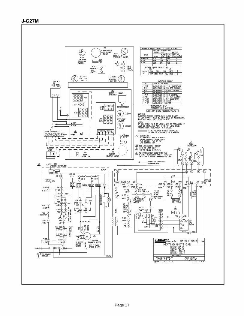
J−G27M
Page 18
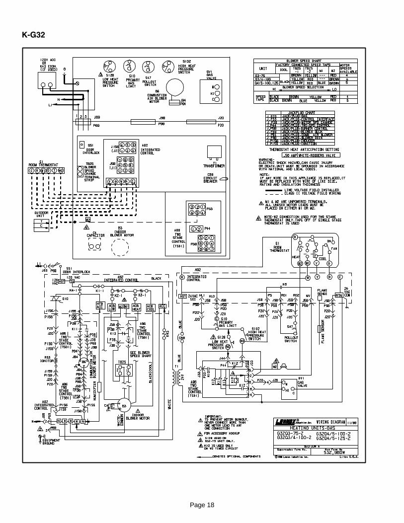
K−G32
Page 19
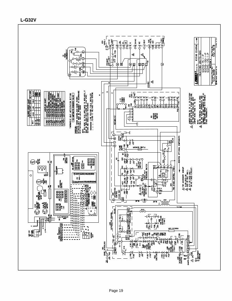
L−G32V
Page 20
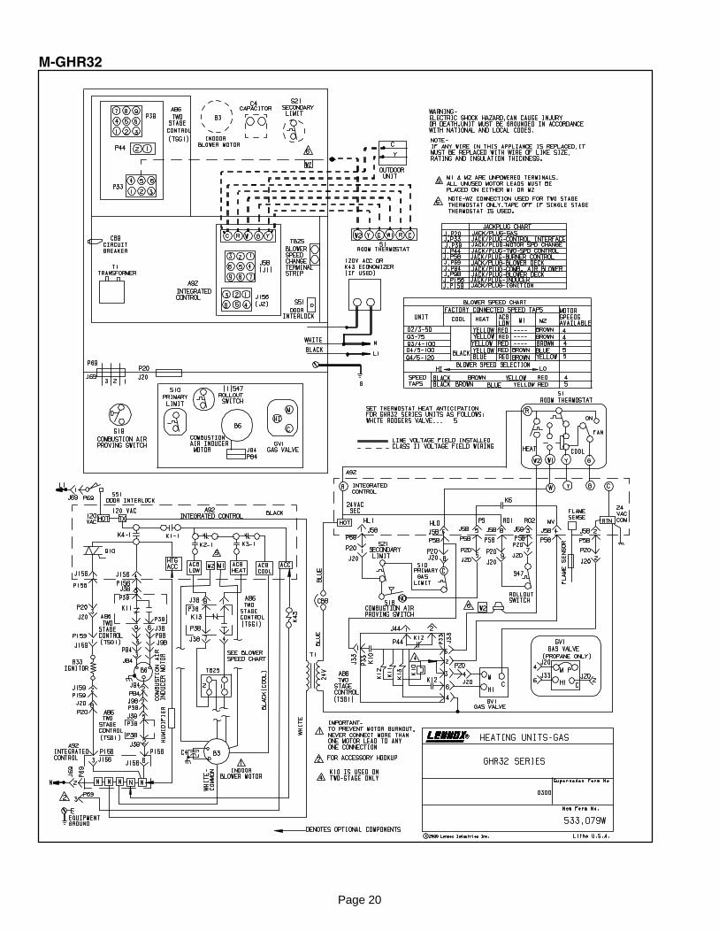
M−GHR32
Page 21
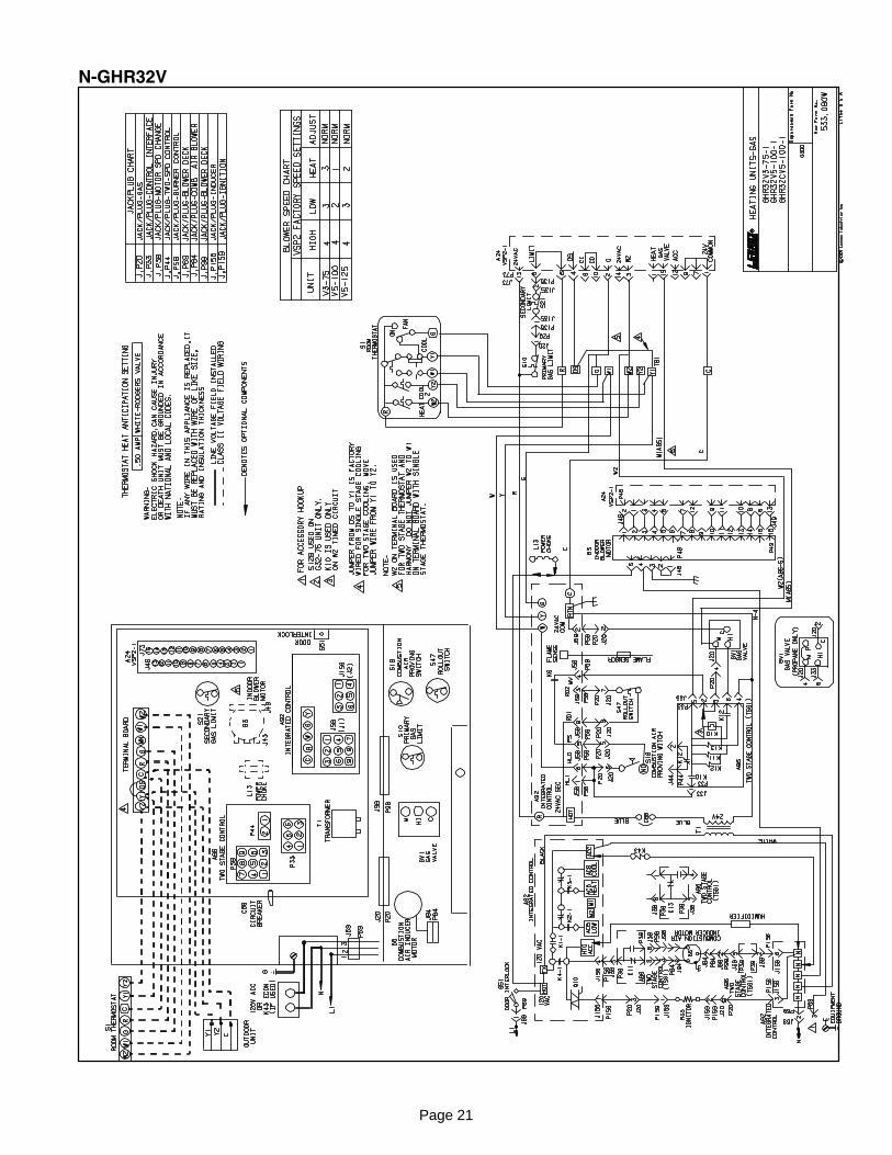
N−GHR32V
Page 22
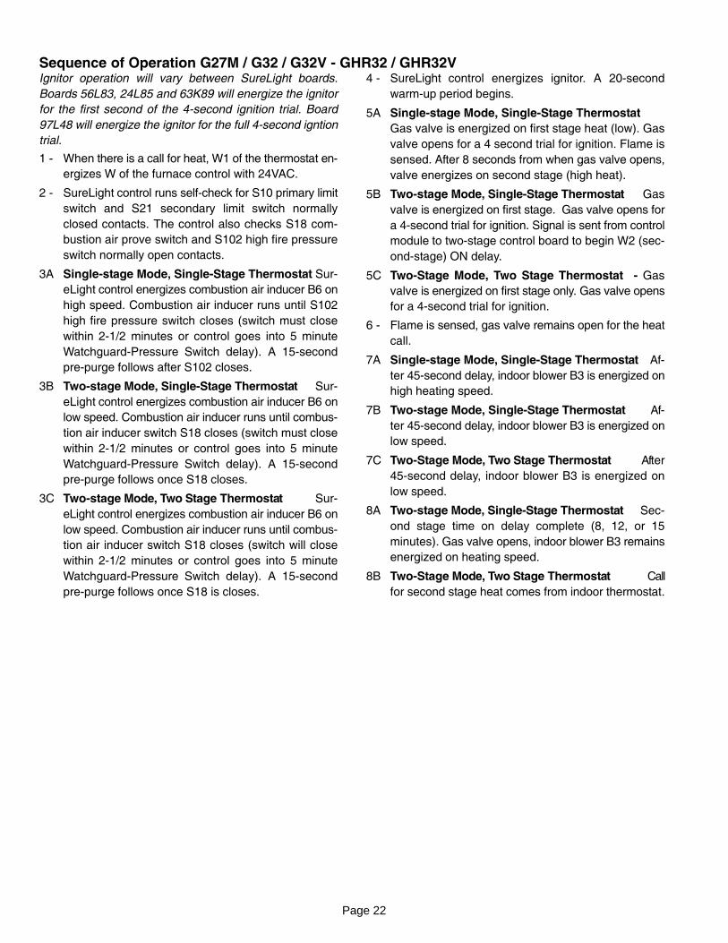
Sequence of Operation G27M / G32 / G32V − GHR32 / GHR32VIgnitor operation will vary between SureLight boards.
Boards 56L83, 24L85 and 63K89 will energize the ignitor
for the first second of the 4−second ignition trial. Board
97L48 will energize the ignitor for the full 4−second igntion
trial.
1 − When there is a call for heat, W1 of the thermostat en�
ergizes W of the furnace control with 24VAC.
2 − SureLight control runs self−check for S10 primary limit
switch and S21 secondary limit switch normally
closed contacts. The control also checks S18 com�
bustion air prove switch and S102 high fire pressure
switch normally open contacts.
3A Single−stage Mode, Single−Stage Thermostat Sur�
eLight control energizes combustion air inducer B6 on
high speed. Combustion air inducer runs until S102
high fire pressure switch closes (switch must close
within 2−1/2 minutes or control goes into 5 minute
Watchguard−Pressure Switch delay). A 15−second
pre−purge follows after S102 closes.
3B Two−stage Mode, Single−Stage Thermostat Sur�
eLight control energizes combustion air inducer B6 on
low speed. Combustion air inducer runs until combus�
tion air inducer switch S18 closes (switch must close
within 2−1/2 minutes or control goes into 5 minute
Watchguard−Pressure Switch delay). A 15−second
pre−purge follows once S18 closes.
3C Two−stage Mode, Two Stage Thermostat Sur�
eLight control energizes combustion air inducer B6 on
low speed. Combustion air inducer runs until combus�
tion air inducer switch S18 closes (switch will close
within 2−1/2 minutes or control goes into 5 minute
Watchguard−Pressure Switch delay). A 15−second
pre−purge follows once S18 is closes.
4 − SureLight control energizes ignitor. A 20−second
warm−up period begins.
5A Single−stage Mode, Single−Stage Thermostat
Gas valve is energized on first stage heat (low). Gas
valve opens for a 4 second trial for ignition. Flame is
sensed. After 8 seconds from when gas valve opens,
valve energizes on second stage (high heat).
5B Two−stage Mode, Single−Stage Thermostat Gas
valve is energized on first stage. Gas valve opens for
a 4−second trial for ignition. Signal is sent from control
module to two−stage control board to begin W2 (sec�
ond−stage) ON delay.
5C Two−Stage Mode, Two Stage Thermostat − Gas
valve is energized on first stage only. Gas valve opens
for a 4−second trial for ignition.
6 − Flame is sensed, gas valve remains open for the heat
call.
7A Single−stage Mode, Single−Stage Thermostat Af�
ter 45−second delay, indoor blower B3 is energized on
high heating speed.
7B Two−stage Mode, Single−Stage Thermostat Af�
ter 45−second delay, indoor blower B3 is energized on
low speed.
7C Two−Stage Mode, Two Stage Thermostat After
45−second delay, indoor blower B3 is energized on
low speed.
8A Two−stage Mode, Single−Stage Thermostat Sec�
ond stage time on delay complete (8, 12, or 15
minutes). Gas valve opens, indoor blower B3 remains
energized on heating speed.
8B Two−Stage Mode, Two Stage Thermostat Call
for second stage heat comes from indoor thermostat.
Page 23
PROVE SWITCH WATCHGUARD(5 MINUTES)
COMBUSTION AIR INDUCER OFF.INDOOR BLOWER OFF.
LED #1 OFFLED #2 SLOW FLASH
HIGH−FIRE PROVESWITCH CLOSED?
GAS VALVE OFF.COMBUSTION AIR INDUCER OFF.
INDOOR BLOWER OFF WITH DELAY.LED #1 OFF
LED #2 SLOW FLASH(Sequence holds until pressure switchcloses or thermostat resets control.)
HEATING SEQUENCE OF OPERATION
NORMAL HEATING MODE ABNORMAL HEATING MODE
CONTROL SELF−CHECK OKAY?
BURNER OFF?(CONTINUOUS FLAME CHECK)
NORMAL OPERATION:LED #1 −− SLOW FLASHLED #2 −− SLOW FLASH
YES
YES
YES
GAS VALVE OFF. COMBUSTION AIR INDUCER OFF.INDOOR BLOWER DELAY OFF.
LED #1 ONLED #2 ON
(RESET CONTROL BY TURNING MAIN POWER OFF.)
POLARITY REVERSED.LED #1 −− FAST FLASHLED #2 −− SLOW FLASH
POWER ON
COMBUSTION AIR INDUCER ON FOR 1 SECOND.
ROLLOUT SWITCH CLOSED?
THERMOSTAT CALLS FOR HEAT:LED #1 −− FAST FLASHLED #2 −− FAST FLASH
GAS VALVE OFF. COMBUSTION AIR INDUCER OFF.INDOOR BLOWER OFF WITH DELAY.LED #1 −− ON. LED #2 −− SLOW FLASH.
SEQUENCE HOLDS UNTIL ROLLOUT SWITCH CLOSES.
GAS VALVE OFF. COMBUSTION AIR INDUCER ON.INDOOR BLOWER ON HEATING SPEED.
LED #1 −− SLOW FLASHLED #2 −− OFF
NO
YES
NO
IS THEREPROPER GROUND?
IS VOLTAGEABOVE 75 VOLTS?
LOW VOLTAGE SIGNAL AT LED HOLDSUNTIL VOLTAGE RISES ABOVE 75 VOLTS.
NO
YESNO
SIGNAL IMPROPERGROUND AT LED.SIGNAL HOLDSUNTIL UNIT IS
PROPERLYGROUNDED.
NO
NO
CONTINUED NEXT PAGE
PRIMARY & SECONDARY LIMIT SWITCHES CLOSED?
COMBUSTION AIR INDUCER OFF.INDOOR BLOWER ON.LED #1 −− SLOW FLASH
LED #2 −− ON
NO
YES
NO
TWO−STAGE MODECALL FOR 1ST STAGE HEAT
TWO−STAGE MODESINGLE STAGE T’STAT
SINGLE−STAGE MODEHIGH HEAT ONLY
COMBUSTION AIR INDUCERON LOW SPEED (� 2.5 MINUTES)
LOW−FIRE PROVESWITCH CLOSED?
PREPURGE15 SECONDS
COMBUSTION AIR INDUCERON HIGH SPEED (� 2.5 MINUTES)
NONO
YES YES
YES
PROVE SWITCH CONTACTS OPEN?(HIGH AND LOW FIRE)
G26, GHR26, 90UGF, G24M, G23X, 80MGF,G27M, G32, G32V, GHR32, GHR32V and G50UH
SEQUENCE
G27M,G32, G32V,GHR32 and GRH32V
SEQUENCEONLY
GAS VALVE OFF. COMBUSTION AIR INDUCER ON.INDOOR BLOWER ON.
LED #1 ALTERNATING FAST FLASHLED#2 ALTERNATING FAST FLASHCHECK FOR BROKEN IGNITOR OR
OPEN IGNITOR CIRCUIT
YES
POLARITYOKAY?
IS COMBUSTION AIR INDUCER ENERGIZED?(HTG ACC ENERGIZES WITH C.A.I.)
*G26, GHR26, 90UGF, G24M,G23X , 80MGF and G50UH
SEQUENCE ONLY
Page 24
GAS VALVE OFF.COMBUSTION AIR INDUCER OFF.
INDOOR BLOWER OFF WITH DELAY.LED #1 OFF
LED #2 SLOW FLASH(Sequence holds until pressure switchcloses or thermostat resets control.)
*IS COMBUSTION AIR INDUCER ENERGIZED?(HTG ACC TERMINAL IS ENERGIZED WITH C.A.B)
*HAS COMBUSTION AIR PROVE SWITCHCLOSED IN 2.5 MINUTES?
YES
*15�SECOND COMBUSTION AIR INDUCERPREPURGE INITIATED BY CLOSED PROVE SWITCH.
YES
YES
HEATING SEQUENCE CONTINUED
IGNITOR WARM�UP −− 20 SECONDS.
YES
4�SECOND TRIAL FOR IGNITION. GAS VALVE OPENS. BOARDS 63K89, 24L85AND 56L83: IGNITOR ENERGIZED FOR1 SECOND AFTER VALVE OPENS.BOARD 97L48,: IGNITOR ENERGIZED THE FULL 4−SECOND TRIAL FOR
IGNITION. NO FLAME SENSED DURING THIS PERIOD.
YES
FLAME STABILIZATION PERIOD.
4 SECONDS
TWO−STAGE MODESINGLE STAGE T’STAT
SINGLE−STAGE MODEHIGH HEAT ONLY
TWO−STAGE MODECALL FOR 1st STAGE HEAT
GAS VALVE OPENHIGH AND LOW FIRE
MAIN GAS VALVE OPENLOW FIRE ONLY
MAIN GAS VALVE OPENLOW FIRE ONLYSECOND STAGETIME ON BEGINS
4 SECONDS
FLAME PRESENT?
YES
FLAME SIGNAL ABOVE 0.7 MICROAMPS?
YES
INDOOR BLOWER ON DELAY BEGINS. AFTER 45SECOND DELAY, ACB HEAT SPEED TERMINAL IS
ENERGIZED. ACC TERMINAL IS ENERGIZED.
YES
FLAME RECTIFICATION CURRENT CHECKCAN FLAME BE PROVEN WITHIN 4
SECONDS AFTER GAS VALVE OPENS?(�0.15 microamps)
INDOOR BLOWERON LOW SPEED
INDOOR BLOWERON HIGH HEATING SPEED
TWO−STAGE MODESINGLE STAGE T’STAT
SINGLE−STAGE MODEHIGH HEAT ONLY
TWO−STAGE MODECALL FOR 1st STAGE HEAT
CONTINUED NEXT PAGE
ÉÉÉÉÉÉÉÉÉÉÉÉÉÉÉÉÉÉÉÉÉÉÉÉÉÉÉÉ
YES
*IS COMBUSTION AIRPROVE SWITCH OPEN?
PROVE SWITCH WATCHGUARD(5 MINUTES)
COMBUSTION AIR INDUCER OFF.INDOOR BLOWER OFF.
LED #1 OFFLED #2 SLOW FLASH
NO
HAS CONTROL RESET IGNITIONSEQUENCE FOUR TIMES?
YES
NO
WATCHGUARD MODE. GAS VALVE OFF.COMBUSTION AIR INDUCER OFF.
INDOOR BLOWER OFF WITH DELAYLEDs SIGNAL WATCHGUARD FAILURE CODE.
IS 60�MINUTE RESET PERIOD COMPLETE?
YES
GAS VALVE OFF. COMBUSTION AIR INDUCER ON.INDOOR BLOWER OFF.
HAS CONTROL FAILED TO SENSE FLAME FORFIVE CONSECUTIVE TRIES DURING A SINGLE
HEAT DEMAND?
LOW FLAME SIGNAL(Does not affect operation of control)
LED #1 −− SLOW FLASHLED #2 −− FAST FLASH
NO
NO
NO
Page 25
DEMAND FOR HEAT SATISFIED.THERMOSTAT OPENS.
TWO−STAGE MODECALL FOR 1st STAGE HEAT
HEATING SEQUENCE CONTINUED
PRIMARY AND SECONDARY LIMITSWITCHES CLOSED?
COMBUSTION AIR PROVESWITCH CLOSED?
YES
ROLLOUT SWITCH CLOSED?
YES
GAS VALVE DE−ENERGIZED.COMBUSTION AIR INDUCER DE−ENERGIZED.
INDOOR BLOWER ON UNTIL SWITCH CLOSES.LED #1 −− SLOW FLASH. LED #2 −− ON.
IS LIMIT SWITCH CLOSED?
YES
HAS PRIMARY/SECONDARY LIMIT RESET(see table 1 DIAGNOSTIC CODES for limit reset operation)
NO
GAS VALVE OFF. COMBUSTION AIR INDUCER OFF.INDOOR BLOWER OFF WITH DELAY.LED #1 −− ON. LED #2 −− SLOW FLASH.
SEQUENCE HOLDS UNTIL ROLLOUT SWITCH CLOSES.
NO
GAS VALVE DE−ENERGIZED.COMBUSTION AIR INDUCER ON.
INDOOR BLOWER OFF WITH DELAYLED #1 −− OFF. LED #2 −− SLOW FLASH.
HAS CAB SWITCH CLOSED IN 2.5 MINUTES?
YESNO
15�SECOND COMBUSTION AIR INDUCER PREPURGEINITIATED BY CLOSED PRESSURE SWITCH.
WATCHGUARD MODE. GAS VALVE OFF.COMBUSTION AIR INDUCER OFF.
INDOOR BLOWER OFF WITH DELAYLEDs SIGNAL WATCHGUARD FAILURE CODE.
IS 60�MINUTE RESET PERIOD COMPLETE?
YES
NO
NO
5�MINUTE PROVE SWITCHWATCHGUARD MODE.
THERMOSTAT DEMAND SATISFIED.
LED #1 & #2 SIMULTANEOUS SLOW FLASHES.
COMB. AIR INDUCER CONTINUES 5�SECOND. POSTPURGE AFTER T’STAT DEMAND IS SATISFIED. IN�
DOOR AIR BLOWER COMPLETES SELECTED �OFF"DELAY BEFORE SHUTTING OFF. ACB HEAT SPEED,
HTG ACC AND ACC TERM. DE−ENERGIZE.
YES
YES
YES
INDOOR BLOWER ONHEAT SPEED?
TWO−STAGE MODESINGLE STAGE T’STAT
PROVE SWITCH CLOSED?
CALL FOR 2nd STAGEHEAT (HIGH FIRE)
FROM THERMOSTAT
2nd STAGE ON DELAYON CONTROL BOARD
COMPLETE (8, 12 OR 15 MIN.)
YES
HIGH FIRE PROVE SWITCH CLOSED?
HIGH FIRE GAS VALVE OPEN? (8 SEC. DELAY)
NOYES YES
COMBUSTION AIR INDUCER ON HIGH SPEED?
NO
TWO−STAGE MODESINGLE STAGE T’STAT
SINGLE−STAGE MODEHIGH HEAT ONLY
TWO−STAGE MODECALL FOR 1st STAGE HEAT
CONTROL CHECKS: FLAME PRESENCE, CLOSED PRIMARY& SECONDARY LIMITS, CLOSED PROVE SWITCHES,
CONTINUOUSLY CLOSED ROLLOUT SWITCHES (duringheating cycle).
SEE PREVIOUS SEQUENCES FOR FAILURE MODES.
GAS VALVE DE−ENERGIZED.
COMBUSTION AIR INDUCERPOST−PURGE −− 5 SECONDS.
INDOOR BLOWERSELECTED TIME OFF DELAY.
Page 26
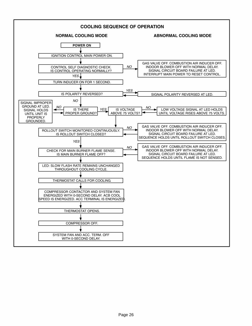
COOLING SEQUENCE OF OPERATION
NORMAL COOLING MODE ABNORMAL COOLING MODE
IGNITION CONTROL MAIN POWER ON.
CONTROL SELF DIAGNOSTIC CHECK.IS CONTROL OPERATING NORMALLY?
YES
SIGNAL POLARITY REVERSED AT LED.
POWER ON
GAS VALVE OFF. COMBUSTION AIR INDUCER OFF.INDOOR BLOWER OFF WITH NORMAL DELAY.
SIGNAL CIRCUIT BOARD FAILURE AT LED.INTERRUPT MAIN POWER TO RESET CONTROL.
YES
TURN INDUCER ON FOR 1 SECOND.
IS POLARITY REVERSED?
ROLLOUT SWITCH MONITORED CONTINUOUSLY.IS ROLLOUT SWITCH CLOSED?
CHECK FOR MAIN BURNER FLAME SENSE.IS MAIN BURNER FLAME OFF?
LED: SLOW FLASH RATE REMAINS UNCHANGEDTHROUGHOUT COOLING CYCLE.
THERMOSTAT CALLS FOR COOLING.
COMPRESSOR CONTACTOR AND SYSTEM FANENERGIZED WITH 0�SECOND DELAY. ACB COOL
SPEED IS ENERGIZED. ACC TERMINAL IS ENERGIZED.
COMPRESSOR OFF.
THERMOSTAT OPENS.
SYSTEM FAN AND ACC. TERM. OFFWITH 0�SECOND DELAY.
NO
YES
NO
GAS VALVE OFF. COMBUSTION AIR INDUCER OFF.INDOOR BLOWER OFF WITH NORMAL DELAY.
SIGNAL CIRCUIT BOARD FAILURE AT LED.SEQUENCE HOLDS UNTIL ROLLOUT SWITCH CLOSES.
NO
GAS VALVE OFF. COMBUSTION AIR INDUCER OFF.INDOOR BLOWER OFF WITH NORMAL DELAY.
SIGNAL CIRCUIT BOARD FAILURE AT LED.SEQUENCE HOLDS UNTIL FLAME IS NOT SENSED.
NO
IS THEREPROPER GROUND?
IS VOLTAGEABOVE 75 VOLTS?
LOW VOLTAGE SIGNAL AT LED HOLDSUNTIL VOLTAGE RISES ABOVE 75 VOLTS.
NOYES
NO
SIGNAL IMPROPERGROUND AT LED.SIGNAL HOLDSUNTIL UNIT IS
PROPERLYGROUNDED.
Page 27
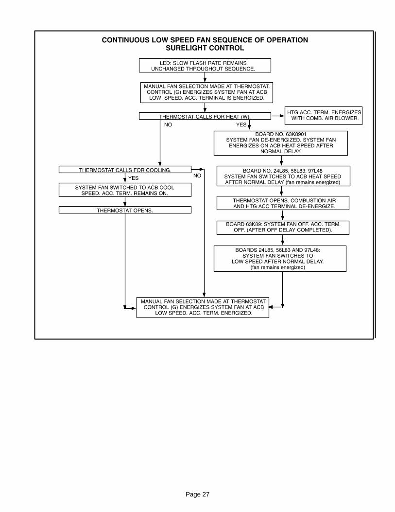
CONTINUOUS LOW SPEED FAN SEQUENCE OF OPERATIONSURELIGHT CONTROL
LED: SLOW FLASH RATE REMAINSUNCHANGED THROUGHOUT SEQUENCE.
MANUAL FAN SELECTION MADE AT THERMOSTAT.CONTROL (G) ENERGIZES SYSTEM FAN AT ACBLOW SPEED. ACC. TERMINAL IS ENERGIZED.
THERMOSTAT CALLS FOR HEAT (W).
THERMOSTAT CALLS FOR COOLING.
BOARD NO. 63K8901SYSTEM FAN DE−ENERGIZED. SYSTEM FANENERGIZES ON ACB HEAT SPEED AFTER
NORMAL DELAY.
THERMOSTAT OPENS. COMBUSTION AIRAND HTG ACC TERMINAL DE−ENERGIZE.
SYSTEM FAN SWITCHED TO ACB COOLSPEED. ACC. TERM. REMAINS ON.
THERMOSTAT OPENS.
BOARD 63K89: SYSTEM FAN OFF. ACC. TERM.OFF. (AFTER OFF DELAY COMPLETED).
MANUAL FAN SELECTION MADE AT THERMOSTAT.CONTROL (G) ENERGIZES SYSTEM FAN AT ACB
LOW SPEED. ACC. TERM. ENERGIZED.
NO YES
YESNO
HTG ACC. TERM. ENERGIZES WITH COMB. AIR BLOWER.
BOARD NO. 24L85, 56L83, 97L48SYSTEM FAN SWITCHES TO ACB HEAT SPEEDAFTER NORMAL DELAY (fan remains energized)
BOARDS 24L85, 56L83 AND 97L48:SYSTEM FAN SWITCHES TO
LOW SPEED AFTER NORMAL DELAY.(fan remains energized)
Page 28
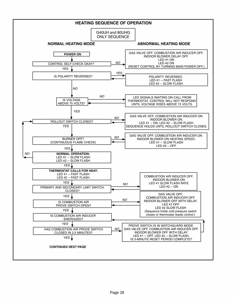
HEATING SEQUENCE OF OPERATION
NORMAL HEATING MODE ABNORMAL HEATING MODE
CONTROL SELF−CHECK OKAY?
BURNER OFF?(CONTINUOUS FLAME CHECK)
NORMAL OPERATION:LED #1 −− SLOW FLASHLED #2 −− SLOW FLASH
YES
YES
YES
GAS VALVE OFF. COMBUSTION AIR INDUCER OFF.INDOOR BLOWER DELAY OFF.
LED #1 ONLED #2 ON
(RESET CONTROL BY TURNING MAIN POWER OFF.)
POLARITY REVERSED.LED #1 −− FAST FLASHLED #2 −− SLOW FLASH
POWER ON
IS POLARITY REVERSED?
ROLLOUT SWITCH CLOSED?
THERMOSTAT CALLS FOR HEAT:LED #1 −− FAST FLASHLED #2 −− FAST FLASH
IS COMBUSTION AIRPROVE SWITCH OPEN?
GAS VALVE OFF. COMBUSTION AIR INDUCER ON.INDOOR BLOWER ON.
LED #1 −− ON. LED #2 −− SLOW FLASH.SEQUENCE HOLDS UNTIL ROLLOUT SWITCH CLOSES.
GAS VALVE OFF. COMBUSTION AIR INDUCER ON.INDOOR BLOWER ON HEATING SPEED.
LED #1 −− SLOW FLASHLED #2 −− OFF
GAS VALVE OFF.COMBUSTION AIR INDUCER OFF.
INDOOR BLOWER OFF WITH DELAY.LED #1 OFF
LED #2 SLOW FLASH(Sequence holds until pressure switchcloses or thermostat resets control.)
NO
NO
YES
NO
IS VOLTAGEABOVE 75 VOLTS?
LED SIGNALS WAITING ON CALL FROMTHERMOSTAT. CONTROL WILL NOT RESPOND
UNTIL VOLTAGE RISES ABOVE 75 VOLTS.
NO
NO
NO
IS COMBUSTION AIR INDUCER ENERGIZED?
HAS COMBUSTION AIR PROVE SWITCHCLOSED IN 2.5 MINUTES?
YES
YESPROVE SWITCH IS IN WATCHGUARD MODE.
GAS VALVE OFF. COMBUSTION AIR INDUCER OFF.INDOOR BLOWER OFF WITH DELAY.
LED #1 −− OFF. LED #2 −− SLOW FLASH.IS 5�MINUTE RESET PERIOD COMPLETE?
NO
PRIMARY AND SECONDARY LIMIT SWITCH.CLOSED?
YES
YES
CONTINUED NEXT PAGE
COMBUSTION AIR INDUCER OFF.INDOOR BLOWER ON
LED #1 SLOW FLASH RATELED #2 −− ON
NO
YES
YES
NO
YES
G40UH and 80UHGONLY SEQUENCE
Page 29
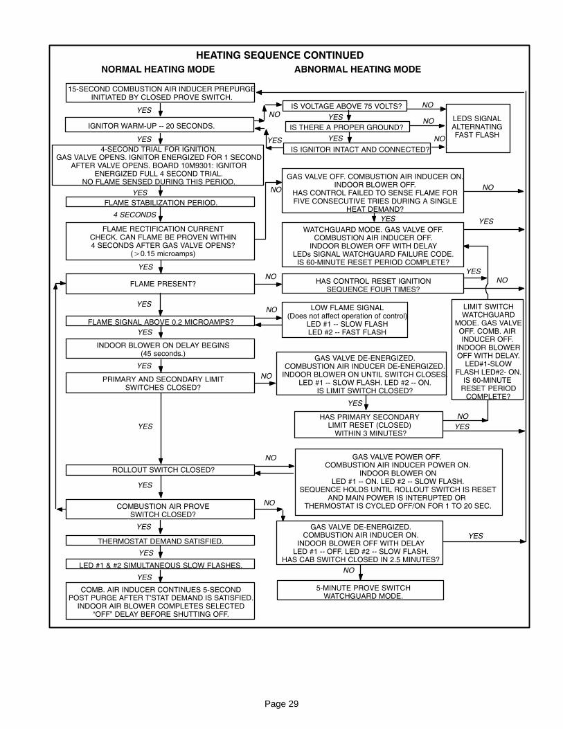
HEATING SEQUENCE CONTINUED
NORMAL HEATING MODE ABNORMAL HEATING MODE
FLAME RECTIFICATION CURRENTCHECK. CAN FLAME BE PROVEN WITHIN4 SECONDS AFTER GAS VALVE OPENS?
(�0.15 microamps)
FLAME PRESENT?
INDOOR BLOWER ON DELAY BEGINS(45 seconds.)
PRIMARY AND SECONDARY LIMITSWITCHES CLOSED?
COMBUSTION AIR PROVESWITCH CLOSED?
LOW FLAME SIGNAL(Does not affect operation of control)
LED #1 −− SLOW FLASHLED #2 −− FAST FLASH
GAS VALVE DE−ENERGIZED.COMBUSTION AIR INDUCER DE−ENERGIZED.
INDOOR BLOWER ON UNTIL SWITCH CLOSES.LED #1 −− SLOW FLASH. LED #2 −− ON.
IS LIMIT SWITCH CLOSED?
GAS VALVE DE−ENERGIZED.COMBUSTION AIR INDUCER ON.
INDOOR BLOWER OFF WITH DELAYLED #1 −− OFF. LED #2 −− SLOW FLASH.
HAS CAB SWITCH CLOSED IN 2.5 MINUTES?
15�SECOND COMBUSTION AIR INDUCER PREPURGEINITIATED BY CLOSED PROVE SWITCH.
YES
IGNITOR WARM�UP −− 20 SECONDS.
YES
4�SECOND TRIAL FOR IGNITION.GAS VALVE OPENS. IGNITOR ENERGIZED FOR 1 SECOND
AFTER VALVE OPENS. BOARD 10M9301: IGNITORENERGIZED FULL 4 SECOND TRIAL.
NO FLAME SENSED DURING THIS PERIOD.
YES
FLAME STABILIZATION PERIOD.
GAS VALVE OFF. COMBUSTION AIR INDUCER ON.INDOOR BLOWER OFF.
HAS CONTROL FAILED TO SENSE FLAME FORFIVE CONSECUTIVE TRIES DURING A SINGLE
HEAT DEMAND?
WATCHGUARD MODE. GAS VALVE OFF.COMBUSTION AIR INDUCER OFF.
INDOOR BLOWER OFF WITH DELAYLEDs SIGNAL WATCHGUARD FAILURE CODE.
IS 60�MINUTE RESET PERIOD COMPLETE?
YES
4 SECONDS
YES
HAS CONTROL RESET IGNITIONSEQUENCE FOUR TIMES?
FLAME SIGNAL ABOVE 0.2 MICROAMPS?
YES
YES
YES
ROLLOUT SWITCH CLOSED?
GAS VALVE POWER OFF. COMBUSTION AIR INDUCER POWER ON.
INDOOR BLOWER ONLED #1 −− ON. LED #2 −− SLOW FLASH.
SEQUENCE HOLDS UNTIL ROLLOUT SWITCH IS RESETAND MAIN POWER IS INTERUPTED OR
THERMOSTAT IS CYCLED OFF/ON FOR 1 TO 20 SEC.
YES
THERMOSTAT DEMAND SATISFIED.
LED #1 & #2 SIMULTANEOUS SLOW FLASHES.
COMB. AIR INDUCER CONTINUES 5�SECONDPOST PURGE AFTER T’STAT DEMAND IS SATISFIED.
INDOOR AIR BLOWER COMPLETES SELECTED�OFF" DELAY BEFORE SHUTTING OFF.
YES
NO
5�MINUTE PROVE SWITCHWATCHGUARD MODE.
YES
IS THERE A PROPER GROUND?
IS VOLTAGE ABOVE 75 VOLTS?
IS IGNITOR INTACT AND CONNECTED?
LEDS SIGNALALTERNATINGFAST FLASH
NO YES
YESYES
YES
YES
NO
NO
NO
NO
NO
NO
NO
NO
YES
YES
NO
NO
NO
NO
YES
YES
HAS PRIMARY SECONDARYLIMIT RESET (CLOSED)
WITHIN 3 MINUTES?
LIMIT SWITCHWATCHGUARD
MODE. GAS VALVEOFF. COMB. AIR INDUCER OFF.
INDOOR BLOWEROFF WITH DELAY.
LED#1−SLOWFLASH LED#2− ON.
IS 60−MINUTE RESET PERIOD
COMPLETE?
YES
Page 30
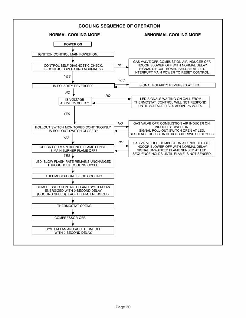
COOLING SEQUENCE OF OPERATION
NORMAL COOLING MODE ABNORMAL COOLING MODE
IGNITION CONTROL MAIN POWER ON.
CONTROL SELF DIAGNOSTIC CHECK.IS CONTROL OPERATING NORMALLY?
YES
SIGNAL POLARITY REVERSED AT LED.
POWER ON
GAS VALVE OFF. COMBUSTION AIR INDUCER OFF.INDOOR BLOWER OFF WITH NORMAL DELAY.
SIGNAL CIRCUIT BOARD FAILURE AT LED.INTERRUPT MAIN POWER TO RESET CONTROL.
YES
IS POLARITY REVERSED?
ROLLOUT SWITCH MONITORED CONTINUOUSLY.IS ROLLOUT SWITCH CLOSED?
CHECK FOR MAIN BURNER FLAME SENSE.IS MAIN BURNER FLAME OFF?
LED: SLOW FLASH RATE REMAINS UNCHANGEDTHROUGHOUT COOLING CYCLE.
THERMOSTAT CALLS FOR COOLING.
COMPRESSOR CONTACTOR AND SYSTEM FANENERGIZED WITH 0�SECOND DELAY
(COOLING SPEED). EAC−H TERM. ENERGIZED.
COMPRESSOR OFF.
THERMOSTAT OPENS.
SYSTEM FAN AND ACC. TERM. OFFWITH 0�SECOND DELAY.
NO
NO
GAS VALVE OFF. COMBUSTION AIR INDUCER ON.INDOOR BLOWER ON.
SIGNAL ROLL�OUT SWITCH OPEN AT LED.SEQUENCE HOLDS UNTIL ROLLOUT SWITCH CLOSES.
GAS VALVE OFF. COMBUSTION AIR INDUCER OFF.INDOOR BLOWER OFF WITH NORMAL DELAY.SIGNAL UNWANTED FLAME SENSED AT LED.
SEQUENCE HOLDS UNTIL FLAME IS NOT SENSED.
IS VOLTAGEABOVE 75 VOLTS?
LED SIGNALS WAITING ON CALL FROMTHERMOSTAT. CONTROL WILL NOT RESPOND
UNTIL VOLTAGE RISES ABOVE 75 VOLTS.
YES
YES
YES
NO
NO
NO
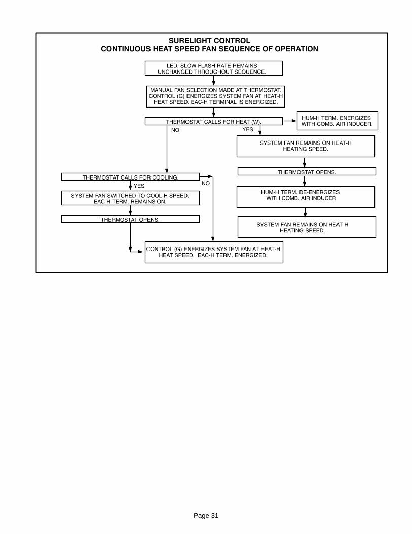
Page 31
SURELIGHT CONTROLCONTINUOUS HEAT SPEED FAN SEQUENCE OF OPERATION
LED: SLOW FLASH RATE REMAINSUNCHANGED THROUGHOUT SEQUENCE.
MANUAL FAN SELECTION MADE AT THERMOSTAT.CONTROL (G) ENERGIZES SYSTEM FAN AT HEAT−H
HEAT SPEED. EAC−H TERMINAL IS ENERGIZED.
THERMOSTAT CALLS FOR HEAT (W).
THERMOSTAT CALLS FOR COOLING.THERMOSTAT OPENS.
SYSTEM FAN SWITCHED TO COOL−H SPEED.EAC−H TERM. REMAINS ON.
THERMOSTAT OPENS.
CONTROL (G) ENERGIZES SYSTEM FAN AT HEAT−HHEAT SPEED. EAC−H TERM. ENERGIZED.
NO YES
YESNO
HUM−H TERM. ENERGIZES WITH COMB. AIR INDUCER.
SYSTEM FAN REMAINS ON HEAT−HHEATING SPEED.
SYSTEM FAN REMAINS ON HEAT−HHEATING SPEED.
HUM−H TERM. DE−ENERGIZES WITH COMB. AIR INDUCER
Page 32
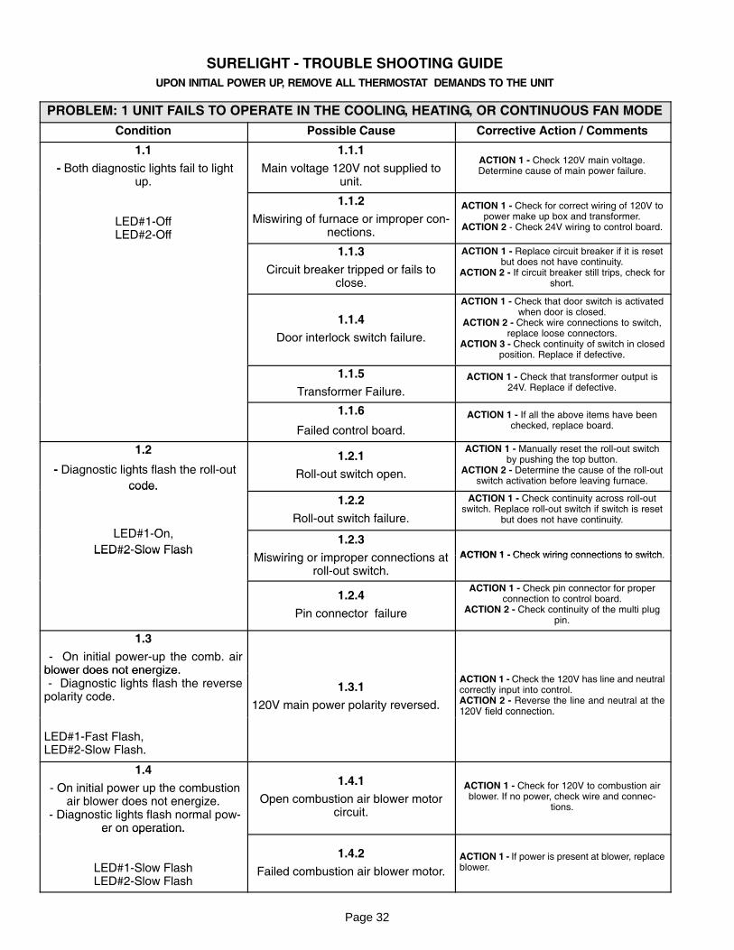
SURELIGHT − TROUBLE SHOOTING GUIDE
UPON INITIAL POWER UP, REMOVE ALL THERMOSTAT DEMANDS TO THE UNIT
PROBLEM: 1 UNIT FAILS TO OPERATE IN THE COOLING, HEATING, OR CONTINUOUS FAN MODE
Condition Possible Cause Corrective Action / Comments
1.1
− Both diagnostic lights fail to lightup.
1.1.1
Main voltage 120V not supplied tounit.
ACTION 1 − Check 120V main voltage.Determine cause of main power failure.
LED#1−OffLED#2−Off
1.1.2
Miswiring of furnace or improper con�nections.
ACTION 1 − Check for correct wiring of 120V topower make up box and transformer.
ACTION 2 − Check 24V wiring to control board.
1.1.3
Circuit breaker tripped or fails toclose.
ACTION 1 − Replace circuit breaker if it is resetbut does not have continuity.
ACTION 2 − If circuit breaker still trips, check forshort.
1.1.4
Door interlock switch failure.
ACTION 1 − Check that door switch is activatedwhen door is closed.
ACTION 2 − Check wire connections to switch,replace loose connectors.
ACTION 3 − Check continuity of switch in closedposition. Replace if defective.
1.1.5
Transformer Failure.
ACTION 1 − Check that transformer output is24V. Replace if defective.
1.1.6
Failed control board.
ACTION 1 − If all the above items have beenchecked, replace board.
1.2
− Diagnostic lights flash the roll−out
code.
1.2.1
Roll−out switch open.
ACTION 1 − Manually reset the roll−out switchby pushing the top button.
ACTION 2 − Determine the cause of the roll−outswitch activation before leaving furnace.code.
LED#1 O
1.2.2
Roll−out switch failure.
ACTION 1 − Check continuity across roll−outswitch. Replace roll−out switch if switch is reset
but does not have continuity.
LED#1−On,
LED#2−Slow Flash1.2.3
Mi i i i ti t ACTION 1 − Check wiring connections to switchLED#2 Slow FlashMiswiring or improper connections at
roll−out switch.
ACTION 1 − Check wiring connections to switch.
1.2.4
Pin connector failure
ACTION 1 − Check pin connector for properconnection to control board.
ACTION 2 − Check continuity of the multi plugpin.
1.3
− On initial power−up the comb. airblower does not energize.blower does not energize. − Diagnostic lights flash the reversepolarity code.
1.3.1
120V main power polarity reversed.
ACTION 1 − Check the 120V has line and neutralcorrectly input into control.ACTION 2 − Reverse the line and neutral at the120V field connection.
LED#1−Fast Flash,LED#2−Slow Flash.
120V field connection.
1.4
− On initial power up the combustionair blower does not energize.
− Diagnostic lights flash normal pow�er on operation.
1.4.1
Open combustion air blower motorcircuit.
ACTION 1 − Check for 120V to combustion airblower. If no power, check wire and connec�
tions.
er on operation.
LED#1−Slow FlashLED#2−Slow Flash
1.4.2
Failed combustion air blower motor.
ACTION 1 − If power is present at blower, replaceblower.
Page 33
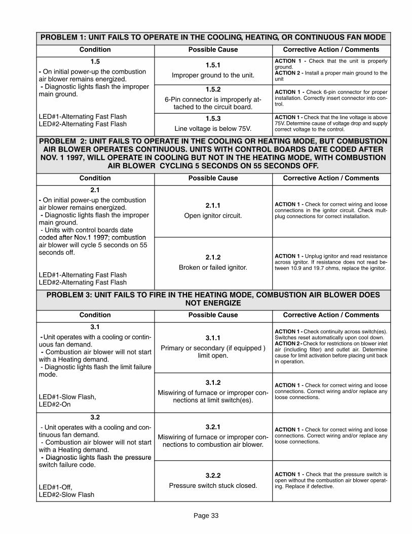
PROBLEM 1: UNIT FAILS TO OPERATE IN THE COOLING, HEATING, OR CONTINUOUS FAN MODE
Condition Possible Cause Corrective Action / Comments
1.5
− On initial power−up the combustionair blower remains energized.
Di ti li ht fl h th i
1.5.1
Improper ground to the unit.
ACTION 1 − Check that the unit is properlyground.ACTION 2 − Install a proper main ground to theunitg
− Diagnostic lights flash the impropermain ground.
1.5.2
6−Pin connector is improperly at�tached to the circuit board.
ACTION 1 − Check 6−pin connector for properinstallation. Correctly insert connector into con�trol.
LED#1−Alternating Fast FlashLED#2−Alternating Fast Flash
1.5.3
Line voltage is below 75V.
ACTION 1 − Check that the line voltage is above75V. Determine cause of voltage drop and supplycorrect voltage to the control.
PROBLEM 2: UNIT FAILS TO OPERATE IN THE COOLING OR HEATING MODE, BUT COMBUSTIONAIR BLOWER OPERATES CONTINUOUS. UNITS WITH CONTROL BOARDS DATE CODED AFTER
NOV. 1 1997, WILL OPERATE IN COOLING BUT NOT IN THE HEATING MODE, WITH COMBUSTIONAIR BLOWER CYCLING 5 SECONDS ON 55 SECONDS OFF.
Condition Possible Cause Corrective Action / Comments
2.1
− On initial power−up the combustionair blower remains energized. − Diagnostic lights flash the impropermain ground. − Units with control boards datecoded after Nov 1 1997; combustion
2.1.1
Open ignitor circuit.
ACTION 1 − Check for correct wiring and looseconnections in the ignitor circuit. Check mult−plug connections for correct installation.
coded after Nov.1 1997; combustionair blower will cycle 5 seconds on 55seconds off.
LED#1−Alternating Fast FlashLED#2−Alternating Fast Flash
2.1.2
Broken or failed ignitor.
ACTION 1 − Unplug ignitor and read resistanceacross ignitor. If resistance does not read be�tween 10.9 and 19.7 ohms, replace the ignitor.
PROBLEM 3: UNIT FAILS TO FIRE IN THE HEATING MODE, COMBUSTION AIR BLOWER DOESNOT ENERGIZE
Condition Possible Cause Corrective Action / Comments
3.1
− Unit operates with a cooling or contin�uous fan demand. − Combustion air blower will not startwith a Heating demand. − Diagnostic lights flash the limit failure
d
3.1.1
Primary or secondary (if equipped )limit open.
ACTION 1 − Check continuity across switch(es).Switches reset automatically upon cool down.ACTION 2 − Check for restrictions on blower inletair (including filter) and outlet air. Determinecause for limit activation before placing unit backin operation.
g gmode.
LED#1−Slow Flash,LED#2−On
3.1.2
Miswiring of furnace or improper con�nections at limit switch(es).
ACTION 1 − Check for correct wiring and looseconnections. Correct wiring and/or replace anyloose connections.
3.2
− Unit operates with a cooling and con�tinuous fan demand. − Combustion air blower will not startwith a Heating demand. − Diagnostic lights flash the pressure
3.2.1
Miswiring of furnace or improper con�nections to combustion air blower.
ACTION 1 − Check for correct wiring and looseconnections. Correct wiring and/or replace anyloose connections.
− Diagnostic lights flash the pressureswitch failure code.
LED#1−Off,LED#2−Slow Flash
3.2.2
Pressure switch stuck closed.
ACTION 1 − Check that the pressure switch isopen without the combustion air blower operat�ing. Replace if defective.
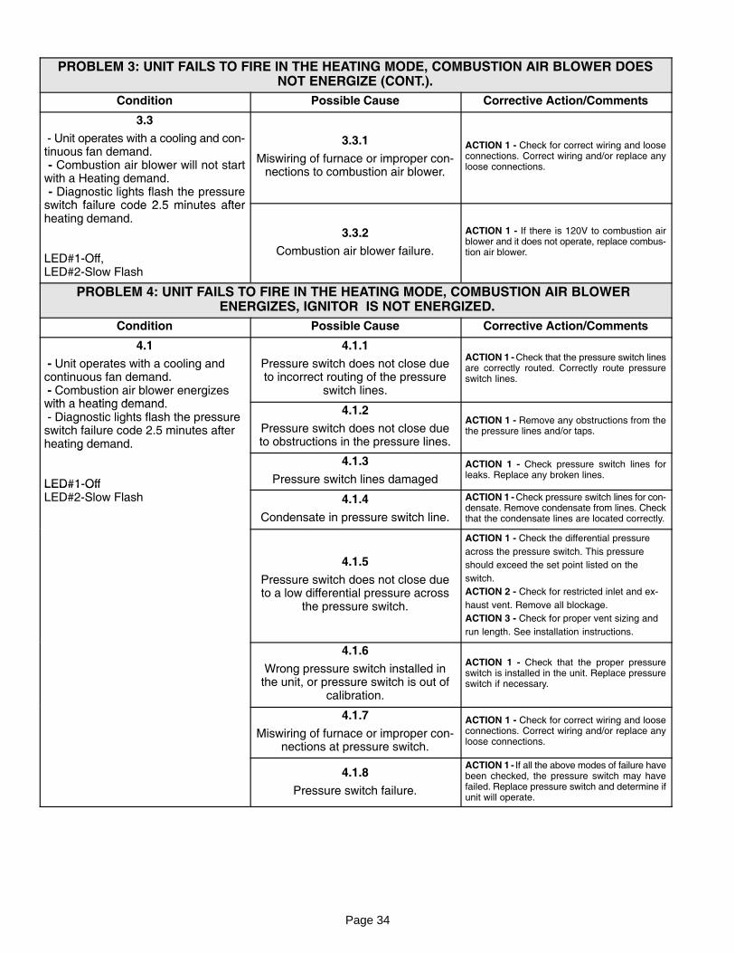
Page 34
PROBLEM 3: UNIT FAILS TO FIRE IN THE HEATING MODE, COMBUSTION AIR BLOWER DOESNOT ENERGIZE (CONT.).
Condition Possible Cause Corrective Action/Comments
3.3
− Unit operates with a cooling and con�tinuous fan demand. − Combustion air blower will not startwith a Heating demand. − Diagnostic lights flash the pressureswitch failure code 2 5 minutes after
3.3.1
Miswiring of furnace or improper con�nections to combustion air blower.
ACTION 1 − Check for correct wiring and looseconnections. Correct wiring and/or replace anyloose connections.
switch failure code 2.5 minutes afterheating demand.
LED#1−Off, LED#2−Slow Flash
3.3.2
Combustion air blower failure.
ACTION 1 − If there is 120V to combustion airblower and it does not operate, replace combus�tion air blower.
PROBLEM 4: UNIT FAILS TO FIRE IN THE HEATING MODE, COMBUSTION AIR BLOWER ENERGIZES, IGNITOR IS NOT ENERGIZED.
Condition Possible Cause Corrective Action/Comments
4.1
− Unit operates with a cooling andcontinuous fan demand. − Combustion air blower energizeswith a heating demand
4.1.1
Pressure switch does not close dueto incorrect routing of the pressure
switch lines.
ACTION 1 − Check that the pressure switch linesare correctly routed. Correctly route pressureswitch lines.
with a heating demand. − Diagnostic lights flash the pressureswitch failure code 2.5 minutes afterheating demand.
4.1.2
Pressure switch does not close dueto obstructions in the pressure lines.
ACTION 1 − Remove any obstructions from thethe pressure lines and/or taps.
g
LED#1−Off
4.1.3
Pressure switch lines damaged
ACTION 1 − Check pressure switch lines forleaks. Replace any broken lines.
LED#1 OffLED#2−Slow Flash 4.1.4
Condensate in pressure switch line.
ACTION 1 − Check pressure switch lines for con�densate. Remove condensate from lines. Checkthat the condensate lines are located correctly.
4.1.5
Pressure switch does not close dueto a low differential pressure across
the pressure switch.
ACTION 1 − Check the differential pressure
across the pressure switch. This pressure
should exceed the set point listed on the
switch.
ACTION 2 − Check for restricted inlet and ex�
haust vent. Remove all blockage.
ACTION 3 − Check for proper vent sizing and
run length. See installation instructions.
4.1.6
Wrong pressure switch installed inthe unit, or pressure switch is out of
calibration.
ACTION 1 − Check that the proper pressureswitch is installed in the unit. Replace pressureswitch if necessary.
4.1.7
Miswiring of furnace or improper con�nections at pressure switch.
ACTION 1 − Check for correct wiring and looseconnections. Correct wiring and/or replace anyloose connections.
4.1.8
Pressure switch failure.
ACTION 1 − If all the above modes of failure havebeen checked, the pressure switch may havefailed. Replace pressure switch and determine ifunit will operate.
Page 35
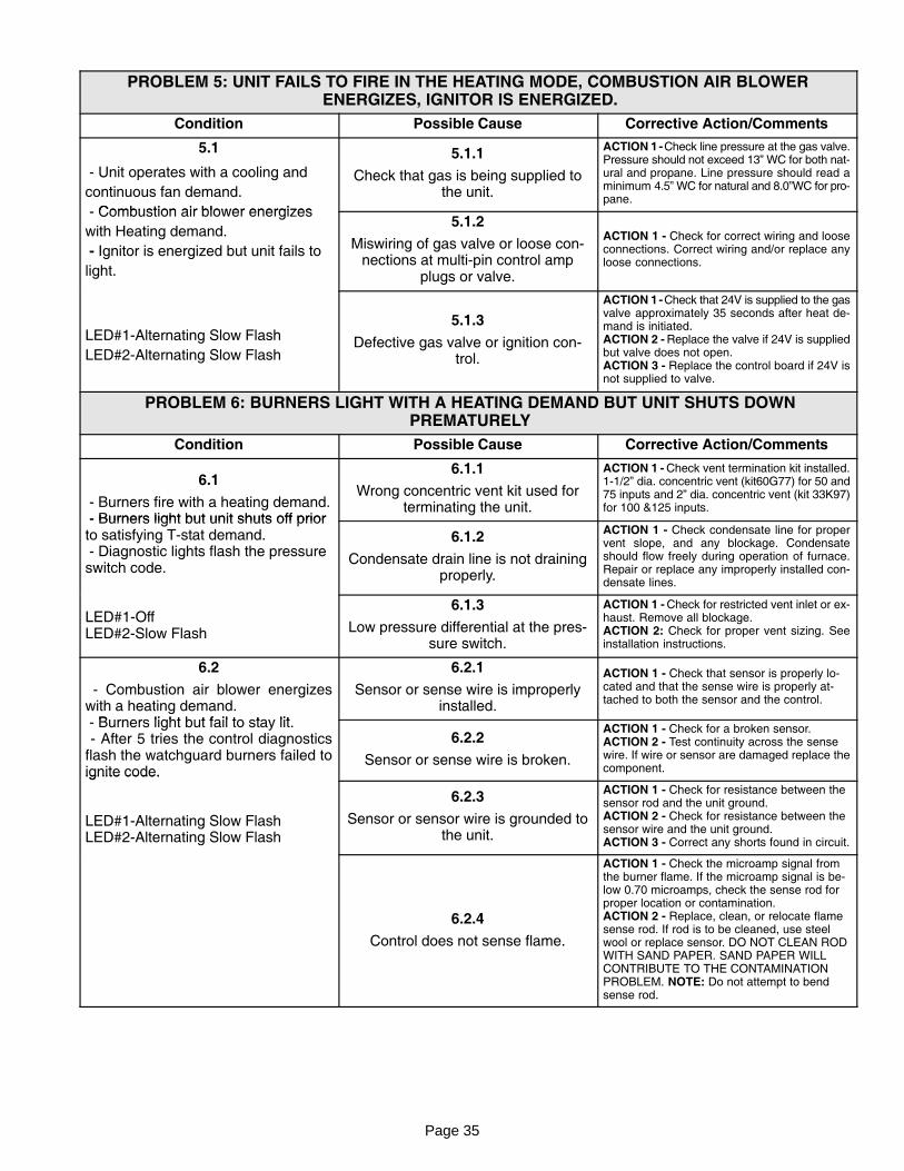
PROBLEM 5: UNIT FAILS TO FIRE IN THE HEATING MODE, COMBUSTION AIR BLOWER ENERGIZES, IGNITOR IS ENERGIZED.
Condition Possible Cause Corrective Action/Comments
5.1
− Unit operates with a cooling and
continuous fan demand.
Combustion air blower energizes
5.1.1
Check that gas is being supplied tothe unit.
ACTION 1 − Check line pressure at the gas valve.Pressure should not exceed 13" WC for both nat�ural and propane. Line pressure should read aminimum 4.5" WC for natural and 8.0"WC for pro�pane.
− Combustion air blower energizes
with Heating demand.
− Ignitor is energized but unit fails to
light.
5.1.2
Miswiring of gas valve or loose con�nections at multi−pin control amp
plugs or valve.
ACTION 1 − Check for correct wiring and looseconnections. Correct wiring and/or replace anyloose connections.
LED#1−Alternating Slow Flash
LED#2−Alternating Slow Flash
5.1.3
Defective gas valve or ignition con�trol.
ACTION 1 − Check that 24V is supplied to the gasvalve approximately 35 seconds after heat de�mand is initiated.ACTION 2 − Replace the valve if 24V is suppliedbut valve does not open.ACTION 3 − Replace the control board if 24V isnot supplied to valve.
PROBLEM 6: BURNERS LIGHT WITH A HEATING DEMAND BUT UNIT SHUTS DOWN PREMATURELY
Condition Possible Cause Corrective Action/Comments
6.1
− Burners fire with a heating demand.− Burners light but unit shuts off prior
6.1.1
Wrong concentric vent kit used forterminating the unit.
ACTION 1 − Check vent termination kit installed.1−1/2" dia. concentric vent (kit60G77) for 50 and75 inputs and 2" dia. concentric vent (kit 33K97)for 100 &125 inputs.
− Burners light but unit shuts off priorto satisfying T−stat demand. − Diagnostic lights flash the pressureswitch code.
6.1.2
Condensate drain line is not drainingproperly.
ACTION 1 − Check condensate line for propervent slope, and any blockage. Condensateshould flow freely during operation of furnace.Repair or replace any improperly installed con�densate lines.
LED#1−OffLED#2−Slow Flash
6.1.3
Low pressure differential at the pres�sure switch.
ACTION 1 − Check for restricted vent inlet or ex�haust. Remove all blockage.ACTION 2: Check for proper vent sizing. Seeinstallation instructions.
6.2
− Combustion air blower energizeswith a heating demand.
B li ht b t f il t t lit
6.2.1
Sensor or sense wire is improperlyinstalled.
ACTION 1 − Check that sensor is properly lo�cated and that the sense wire is properly at�tached to both the sensor and the control.
− Burners light but fail to stay lit. − After 5 tries the control diagnosticsflash the watchguard burners failed toignite code.
6.2.2
Sensor or sense wire is broken.
ACTION 1 − Check for a broken sensor.ACTION 2 − Test continuity across the sensewire. If wire or sensor are damaged replace thecomponent.ignite code.
LED#1−Alternating Slow FlashLED#2−Alternating Slow Flash
6.2.3
Sensor or sensor wire is grounded tothe unit.
ACTION 1 − Check for resistance between thesensor rod and the unit ground.ACTION 2 − Check for resistance between thesensor wire and the unit ground.ACTION 3 − Correct any shorts found in circuit.
6.2.4
Control does not sense flame.
ACTION 1 − Check the microamp signal fromthe burner flame. If the microamp signal is be�low 0.70 microamps, check the sense rod forproper location or contamination.ACTION 2 − Replace, clean, or relocate flamesense rod. If rod is to be cleaned, use steelwool or replace sensor. DO NOT CLEAN RODWITH SAND PAPER. SAND PAPER WILLCONTRIBUTE TO THE CONTAMINATIONPROBLEM. NOTE: Do not attempt to bendsense rod.
Page 36
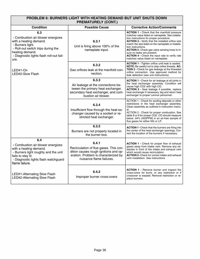
PROBLEM 6: BURNERS LIGHT WITH HEATING DEMAND BUT UNIT SHUTS DOWN PREMATURELY (CONT.)
Condition Possible Cause Corrective Action/Comments
6.3
− Combustion air blower energizeswith a heating demand. − Burners light. − Roll−out switch trips during theheating demand. − Diagnostic lights flash roll−out fail�ure.
6.3.1
Unit is firing above 100% of thenameplate input.
ACTION 1 − Check that the manifold pressurematches value listed on nameplate. See installa�tion instructions for proper procedure.ACTION 2 − Verify that the installed orifice sizematch the size listed on the nameplate or installa�tion instructions.ACTION 3 − Check gas valve sensing hose to in�sure no leaks are present.ACTION 4 − Check the input rate to verify ratematches value listed on nameplate.ure.
LED#1−OnLED#2−Slow Flash
6.3.2
Gas orifices leak at the manifold con�nection.
ACTION 1 − Tighten orifice until leak is sealed.NOTE: Be careful not to strip orifice threads. AC�TION 2 − Check for gas leakage at the threadedorifice connection. Use approved method forleak detection (see unit instructions).
6.3.3
Air leakage at the connections be�tween the primary heat exchanger,
secondary heat exchanger, and com�bustion air blower.
ACTION 1 − Check for air leakage at all joints inthe heat exchanger assembly. Condition willcause high CO2 with high CO.ACTION 2 − Seal leakage if possible, replaceheat exchanger if necessary, tag and return heatexchanger to proper Lennox personnel.
6.3.4
Insufficient flow through the heat ex�changer caused by a sooted or re�
stricted heat exchanger.
ACTION 1 − Check for sooting deposits or otherrestrictions in the heat exchanger assembly.Clean assembly as outlined in instruction manu�al.ACTION 2 − Check for proper combustion. Seetable 8 or 9 for proper CO2. CO should measurebelow .04% (400PPM) in an air−free sample offlue gases for either NG or LP.
6.3.5
Burners are not properly located inthe burner box.
ACTION 1 − Check that the burners are firing intothe center of the heat exchanger openings. Cor�rect the location of the burners if necessary.
6.4
− Combustion air blower energizeswith a heating demand. − Burners light roughly and the unitfails to stay lit. − Diagnostic lights flash watchguardflame failure.
6.4.1
Recirculation of flue gases. This con�dition causes rough ignitions and op�eration. Problem is characterized by
nuisance flame failures.
ACTION 1 − Check for proper flow of exhaustgases away from intake vent. Remove any ob�stacles in front of the intake and exhaust ventwhich would cause recirculation.ACTION 2 − Check for correct intake and exhaustvent installation. See instructions
flame failure.
LED#1−Alternating Slow FlashLED#2−Alternating Slow Flash
6.4.2
Improper burner cross−overs
ACTION 1 − Remove burner and inspect thecross−overs for burrs, or any restriction or ifcrossover is warped. Remove restriction or re�place burners.
Page 37
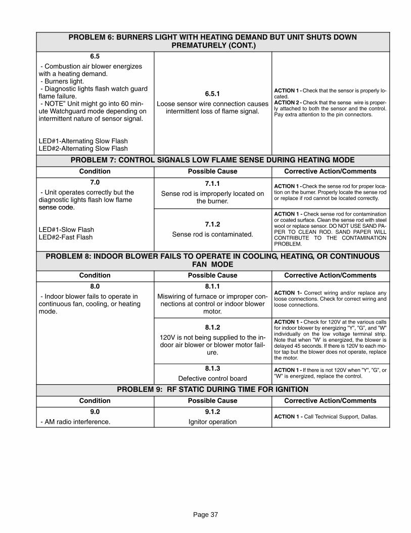
PROBLEM 6: BURNERS LIGHT WITH HEATING DEMAND BUT UNIT SHUTS DOWN PREMATURELY (CONT.)
6.5
− Combustion air blower energizeswith a heating demand. − Burners light. − Diagnostic lights flash watch guardflame failure. − NOTE" Unit might go into 60 min�ute Watchguard mode depending onintermittent nature of sensor signal.
LED#1−Alternating Slow FlashLED#2−Alternating Slow Flash
6.5.1
Loose sensor wire connection causesintermittent loss of flame signal.
ACTION 1 − Check that the sensor is properly lo�cated.ACTION 2 − Check that the sense wire is proper�ly attached to both the sensor and the control.Pay extra attention to the pin connectors.
PROBLEM 7: CONTROL SIGNALS LOW FLAME SENSE DURING HEATING MODE
Condition Possible Cause Corrective Action/Comments
7.0
− Unit operates correctly but thediagnostic lights flash low flamesense code
7.1.1
Sense rod is improperly located onthe burner.
ACTION 1 − Check the sense rod for proper loca�tion on the burner. Properly locate the sense rodor replace if rod cannot be located correctly.
sense code.
LED#1−Slow FlashLED#2−Fast Flash
7.1.2
Sense rod is contaminated.
ACTION 1 − Check sense rod for contaminationor coated surface. Clean the sense rod with steelwool or replace sensor. DO NOT USE SAND PA�PER TO CLEAN ROD. SAND PAPER WILLCONTRIBUTE TO THE CONTAMINATIONPROBLEM.
PROBLEM 8: INDOOR BLOWER FAILS TO OPERATE IN COOLING, HEATING, OR CONTINUOUSFAN MODE
Condition Possible Cause Corrective Action/Comments
8.0
− Indoor blower fails to operate incontinuous fan, cooling, or heatingmode.
8.1.1
Miswiring of furnace or improper con�nections at control or indoor blower
motor.
ACTION 1− Correct wiring and/or replace anyloose connections. Check for correct wiring andloose connections.
8.1.2
120V is not being supplied to the in�door air blower or blower motor fail�
ure.
ACTION 1 − Check for 120V at the various callsfor indoor blower by energizing "Y", "G", and "W"individually on the low voltage terminal strip.Note that when "W’ is energized, the blower isdelayed 45 seconds. If there is 120V to each mo�tor tap but the blower does not operate, replacethe motor.
8.1.3
Defective control board
ACTION 1 − If there is not 120V when "Y", "G", or"W" is energized, replace the control.
PROBLEM 9: RF STATIC DURING TIME FOR IGNITION
Condition Possible Cause Corrective Action/Comments
9.0
− AM radio interference.
9.1.2
Ignitor operationACTION 1 − Call Technical Support, Dallas.
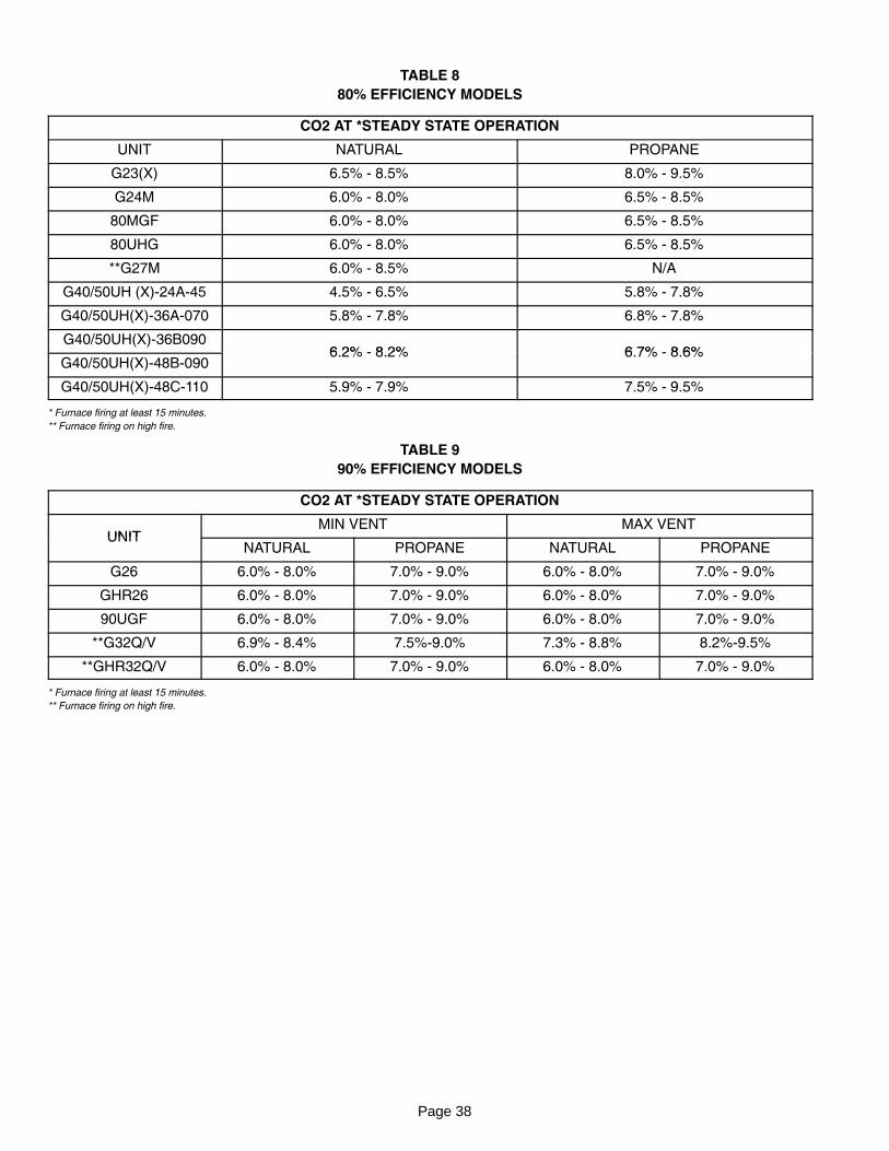
Page 38
TABLE 8
80% EFFICIENCY MODELS
CO2 AT *STEADY STATE OPERATION
UNIT NATURAL PROPANE
G23(X) 6.5% − 8.5% 8.0% − 9.5%
G24M 6.0% − 8.0% 6.5% − 8.5%
80MGF 6.0% − 8.0% 6.5% − 8.5%
80UHG 6.0% − 8.0% 6.5% − 8.5%
**G27M 6.0% − 8.5% N/A
G40/50UH (X)−24A−45 4.5% − 6.5% 5.8% − 7.8%
G40/50UH(X)−36A−070 5.8% − 7.8% 6.8% − 7.8%
G40/50UH(X)−36B0906 2% − 8 2% 6 7% − 8 6%
G40/50UH(X)−48B−0906.2% − 8.2% 6.7% − 8.6%
G40/50UH(X)−48C−110 5.9% − 7.9% 7.5% − 9.5%
* Furnace firing at least 15 minutes.
** Furnace firing on high fire.
TABLE 9
90% EFFICIENCY MODELS
CO2 AT *STEADY STATE OPERATION
UNITMIN VENT MAX VENT
UNITNATURAL PROPANE NATURAL PROPANE
G26 6.0% − 8.0% 7.0% − 9.0% 6.0% − 8.0% 7.0% − 9.0%
GHR26 6.0% − 8.0% 7.0% − 9.0% 6.0% − 8.0% 7.0% − 9.0%
90UGF 6.0% − 8.0% 7.0% − 9.0% 6.0% − 8.0% 7.0% − 9.0%
**G32Q/V 6.9% − 8.4% 7.5%−9.0% 7.3% − 8.8% 8.2%−9.5%
**GHR32Q/V 6.0% − 8.0% 7.0% − 9.0% 6.0% − 8.0% 7.0% − 9.0%
* Furnace firing at least 15 minutes.
** Furnace firing on high fire.
Page 39
SERVICE NOTES