Embed Size (px)
Citation preview
3/6/2018
1
Embodiment Design: Parametric Design
Chapter 8
Part II
1 Dieter/Schmidt, Engineering Design 5e.
©2013. The McGraw-Hill Companies
Embodiment Design in PDP
2 Dieter/Schmidt, Engineering Design 5e.
©2013. The McGraw-Hill Companies
8.6 Parametric Design
What is parametric design?
3 Dieter/Schmidt, Engineering Design 5e.
©2013. The McGraw-Hill Companies
Parametric Design
4
In configuration design the emphasis was on starting with the product
architecture and then working out the best form of each component.
Qualitative reasoning about physical principles and manufacturing
processes played a major role.
In parametric design the attributes of components identified during
configuration design become the design variables for parametric design.
A design variable is an attribute of a part whose value is under the control
of the designer.
This aspect of design is much more analytical than conceptual or
configuration design.
The objective of parametric design is to set values for the design variables
that will produce the best possible design considering both performance
and cost.
Dieter/Schmidt, Engineering Design 5e.
©2013. The McGraw-Hill Companies
Systematic Steps in Parametric Design
Step 1: Formulate the parametric design problem.
Step 2: Generate alternative designs.
Step 3: Analyze the alternative designs.
Step 4: Evaluate the results of the analyses.
Step 5: Refine/Optimize.
5 Dieter/Schmidt, Engineering Design 5e.
©2013. The McGraw-Hill Companies
Parametric Design Example:
Helical Coil Compression Spring
6 Dieter/Schmidt, Engineering Design 5e.
©2013. The McGraw-Hill Companies
3/6/2018
2
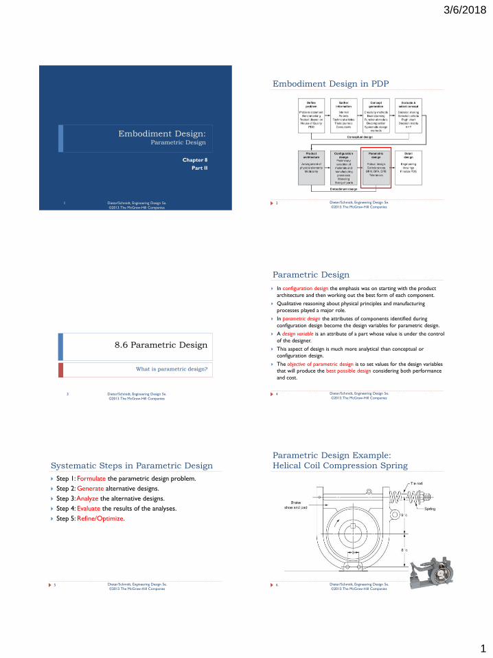
Details of the Spring
7 Dieter/Schmidt, Engineering Design 5e.
©2013. The McGraw-Hill Companies
Design for Manufacturing(DFM) and
Design For Assembly(DFA)
It is imperative that during embodiment design decisions
concerning shape, dimensions, and tolerances should be
closely integrated with manufacturing and assembly
decisions.
This is achieved by having a member of the manufacturing
staff as part of the design team.
Generalized DFM and DFA guidelines have been developed.
Many companies have specific guidelines in their design
manuals.
The reason for the strong emphasis on DFM/DFA is the
realization by U.S. manufacturers in the 1980s that
manufacturing needs to be linked with design to produce
quality and cost-effective designs. 8 Dieter/Schmidt, Engineering Design 5e.
©2013. The McGraw-Hill Companies
Failure Modes and Effect Analysis
(FMEA)
A failure is any aspect of the design or manufacturing
process that renders a component, assembly, or system
incapable of performing its intended function.
FMEA is a methodology for determining all possible ways
that components can fail and establishing the effect of
failure on the system.
FMEA analysis is routinely performed during embodiment
design.
9 Dieter/Schmidt, Engineering Design 5e.
©2013. The McGraw-Hill Companies
Design for Reliability and Safety
Reliability is a measurement of the ability of a component
or system to operate without interruption of service or
failure in the service environment.
Durability is the amount of use that a person gets out of a
product before it deteriorates.(it is a measure of the
product lifetime)
Safety involves designing products that will not injure
people or damage property.
A safe design is one that instills confidence in the
customer and does not incur product liability costs.
10 Dieter/Schmidt, Engineering Design 5e.
©2013. The McGraw-Hill Companies
Design for Quality and Robustness
Achieving a quality design places great emphasis on
understanding the needs and wants of the customer.
In the 1980s, there was the realization that the only way to
ensure quality products is to design quality into the product, as
opposed to the then-current thinking that quality products
were produced by careful inspection of the output of the
manufacturing process.
A robust design is one whose performance is insensitive to
variations in the manufacturing process by which it has been
made or in the environment in which it operates.
The methods used to achieve robustness are termed robust
design, which are mostly the work of Genichi Taguchi.
11 Dieter/Schmidt, Engineering Design 5e.
©2013. The McGraw-Hill Companies
Embodiment Design: Dimensions and Tolerances
Chapter 8, Section 8.7
Part III
12 Dieter/Schmidt, Engineering Design 5e.
©2013. The McGraw-Hill Companies
3/6/2018
3
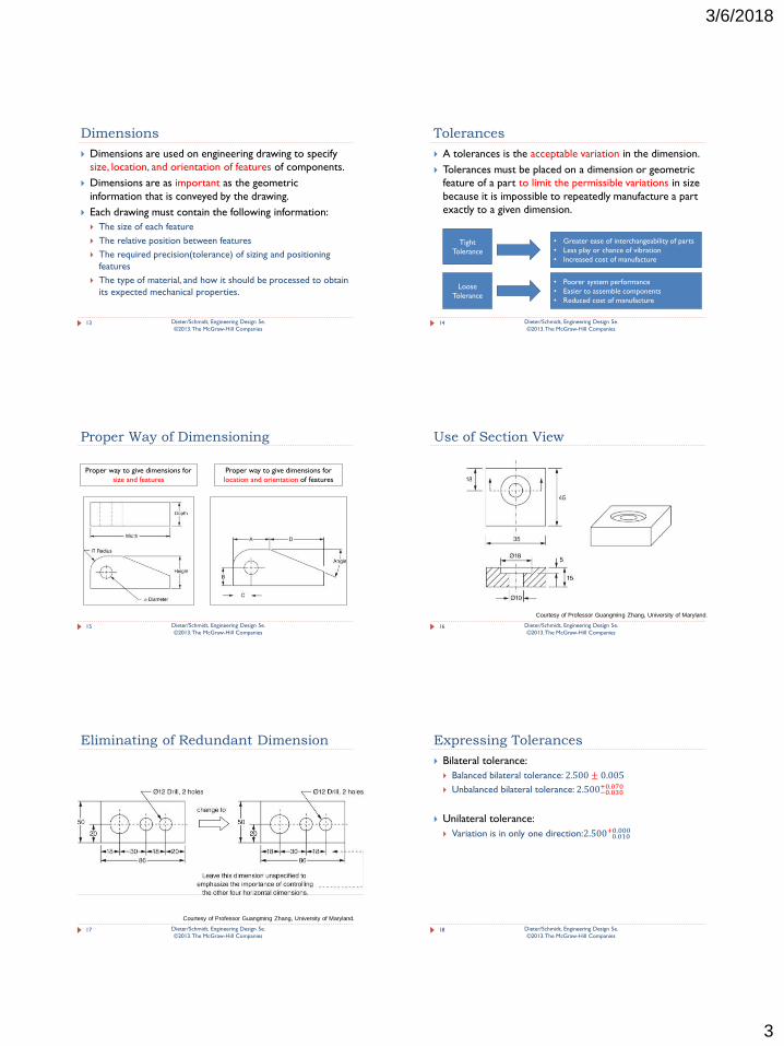
Dimensions
Dimensions are used on engineering drawing to specify
size, location, and orientation of features of components.
Dimensions are as important as the geometric
information that is conveyed by the drawing.
Each drawing must contain the following information:
The size of each feature
The relative position between features
The required precision(tolerance) of sizing and positioning
features
The type of material, and how it should be processed to obtain
its expected mechanical properties.
13 Dieter/Schmidt, Engineering Design 5e.
©2013. The McGraw-Hill Companies
Tolerances
A tolerances is the acceptable variation in the dimension.
Tolerances must be placed on a dimension or geometric
feature of a part to limit the permissible variations in size
because it is impossible to repeatedly manufacture a part
exactly to a given dimension.
14
Tight
Tolerance
• Greater ease of interchangeability of parts
• Less play or chance of vibration
• Increased cost of manufacture
Loose
Tolerance
• Poorer system performance
• Easier to assemble components
• Reduced cost of manufacture
Dieter/Schmidt, Engineering Design 5e.
©2013. The McGraw-Hill Companies
Proper Way of Dimensioning
15
Proper way to give dimensions for
size and features
Proper way to give dimensions for
location and orientation of features
Dieter/Schmidt, Engineering Design 5e.
©2013. The McGraw-Hill Companies
Use of Section View
16 Dieter/Schmidt, Engineering Design 5e.
©2013. The McGraw-Hill Companies
Courtesy of Professor Guangming Zhang, University of Maryland.
Eliminating of Redundant Dimension
17 Dieter/Schmidt, Engineering Design 5e.
©2013. The McGraw-Hill Companies
Courtesy of Professor Guangming Zhang, University of Maryland.
Expressing Tolerances
Bilateral tolerance:
Balanced bilateral tolerance: 2.500 ± 0.005
Unbalanced bilateral tolerance: 2.500−0.030+0.070
Unilateral tolerance:
Variation is in only one direction:2.500 0.010+0.000
18 Dieter/Schmidt, Engineering Design 5e.
©2013. The McGraw-Hill Companies
3/6/2018
4
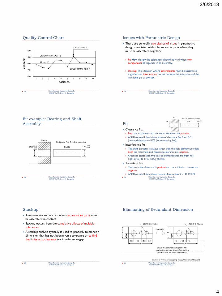
Quality Control Chart
19 Dieter/Schmidt, Engineering Design 5e.
©2013. The McGraw-Hill Companies
Issues with Parametric Design
There are generally two classes of issues in parametric
design associated with tolerances on parts when they
must be assembled together:
Fit: How closely the tolerances should be held when two
components fit together in an assembly.
Stackup: The situation where several parts must be assembled
together and interference occurs because the tolerances of the
individual parts overlap.
20 Dieter/Schmidt, Engineering Design 5e.
©2013. The McGraw-Hill Companies
Fit example: Bearing and Shaft
Assembly
21 Dieter/Schmidt, Engineering Design 5e.
©2013. The McGraw-Hill Companies
Fit
Clearance fits:
Both the maximum and minimum clearances are positive.
ANSI has established nine classes of clearance fits form RC1
(perceptible play) to RC9 (loose running fits).
Interference fits:
The shaft diameter is always larger than the hole diameter, so that
both the maximum and minimum clearance are negative.
ANSI has established five classes of interference fits from FN1
(light drive) to FN5 (heavy shrink).
Transition fits:
The maximum clearance is positive and the minimum clearance is
negative.
ANSI has established three classes of transition fits: LC, LT, LN. 22 Dieter/Schmidt, Engineering Design 5e.
©2013. The McGraw-Hill Companies
Stackup
Tolerance stackup occurs when two or more parts must
be assembled in contact.
Stackup occurs from the cumulative effects of multiple
tolerances.
A stackup analysis typically is used to properly tolerance a
dimension that has not been given a tolerance or to find
the limits on a clearance (or interference) gap.
23 Dieter/Schmidt, Engineering Design 5e.
©2013. The McGraw-Hill Companies
Eliminating of Redundant Dimension
24 Dieter/Schmidt, Engineering Design 5e.
©2013. The McGraw-Hill Companies
Courtesy of Professor Guangming Zhang, University of Maryland.
3/6/2018
5
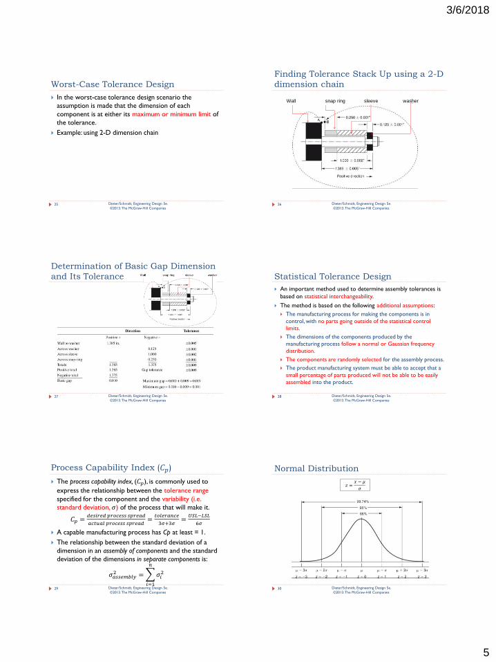
Worst-Case Tolerance Design
In the worst-case tolerance design scenario the
assumption is made that the dimension of each
component is at either its maximum or minimum limit of
the tolerance.
Example: using 2-D dimension chain
25 Dieter/Schmidt, Engineering Design 5e.
©2013. The McGraw-Hill Companies
Finding Tolerance Stack Up using a 2-D
dimension chain
26 Dieter/Schmidt, Engineering Design 5e.
©2013. The McGraw-Hill Companies
Wall snap ring sleeve washer
Determination of Basic Gap Dimension
and Its Tolerance
27 Dieter/Schmidt, Engineering Design 5e.
©2013. The McGraw-Hill Companies
Statistical Tolerance Design
An important method used to determine assembly tolerances is
based on statistical interchangeability.
The method is based on the following additional assumptions:
The manufacturing process for making the components is in
control, with no parts going outside of the statistical control
limits.
The dimensions of the components produced by the
manufacturing process follow a normal or Gaussian frequency
distribution.
The components are randomly selected for the assembly process.
The product manufacturing system must be able to accept that a
small percentage of parts produced will not be able to be easily
assembled into the product.
28 Dieter/Schmidt, Engineering Design 5e.
©2013. The McGraw-Hill Companies
Process Capability Index (𝐶𝑝)
The process capability index, (𝐶𝑝), is commonly used to
express the relationship between the tolerance range
specified for the component and the variability (i.e.
standard deviation, 𝜎) of the process that will make it.
𝐶𝑝 =𝑑𝑒𝑠𝑖𝑟𝑒𝑑 𝑝𝑟𝑜𝑐𝑒𝑠𝑠 𝑠𝑝𝑟𝑒𝑎𝑑
𝑎𝑐𝑡𝑢𝑎𝑙 𝑝𝑟𝑜𝑐𝑒𝑠𝑠 𝑠𝑝𝑟𝑒𝑎𝑑=𝑡𝑜𝑙𝑒𝑟𝑎𝑛𝑐𝑒
3𝜎+3𝜎=𝑈𝑆𝐿−𝐿𝑆𝐿
6𝜎
A capable manufacturing process has Cp at least = 1.
The relationship between the standard deviation of a
dimension in an assembly of components and the standard
deviation of the dimensions in separate components is:
𝜎𝑎𝑠𝑠𝑒𝑚𝑏𝑙𝑦2 = 𝜎𝑖
2
𝑛
𝑖=1
29 Dieter/Schmidt, Engineering Design 5e.
©2013. The McGraw-Hill Companies
Normal Distribution
30
𝑧 =𝑥 − 𝜇
𝜎
Dieter/Schmidt, Engineering Design 5e.
©2013. The McGraw-Hill Companies
3/6/2018
6
Determination of Gap and Its Tolerance
Using Statistical Method
31 Dieter/Schmidt, Engineering Design 5e.
©2013. The McGraw-Hill Companies
Determination of Variation Contribution
of Each Part in an Assembly
32 Dieter/Schmidt, Engineering Design 5e.
©2013. The McGraw-Hill Companies
Advanced Tolerance Analysis
When many dimensions are involved, and the mechanism
is definitely three-dimensional, a system of tolerance charts
has been developed.
For tolerance analysis on three-dimensional problems,
specialized computer programs are almost mandatory.
Some of these are standalone software applications, but
most major CAD systems have packages to perform
tolerance analysis.
They also typically support the Geometric Dimensioning
and Tolerancing (GD&T) system.
33 Dieter/Schmidt, Engineering Design 5e.
©2013. The McGraw-Hill Companies
Geometric Dimensioning and
Tolerancing (GD&T)
In engineering practice this and many other tolerance
issues are described and specified by a system of
Geometric Dimensioning and Tolerancing (GD&T) based on
ASME standard Y14.5–2009.
GD&T is a universal design language to precisely convey
design intent. (Refer to Figure 8.25)
Two important pieces of information in an engineering
drawing brought by GD&T:
it clearly defines the datum surfaces from which
dimensions are measured
it specifies a tolerance zone that must contain all points of
a geometric feature
34 Dieter/Schmidt, Engineering Design 5e.
©2013. The McGraw-Hill Companies
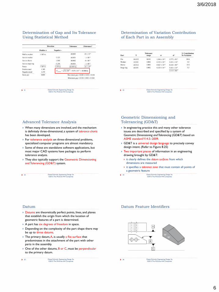
Datum
Datums are theoretically perfect points, lines, and planes
that establish the origin from which the location of
geometric features of a part is determined.
A part has six degrees of freedom in space.
Depending on the complexity of the part shape there may
be up to three datums.
The primary datum, A, is usually a flat surface that
predominates in the attachment of the part with other
parts in the assembly.
One of the other datums, B or C, must be perpendicular
to the primary datum.
35 Dieter/Schmidt, Engineering Design 5e.
©2013. The McGraw-Hill Companies
Datum Feature Identifiers
36 Dieter/Schmidt, Engineering Design 5e.
©2013. The McGraw-Hill Companies
3/6/2018
7
Geometric Tolerances
Geometric tolerances can be defined for the following
characteristics of geometric features:
Form:
Flatness, straightness, circularity, cylindricity
Profile:
Line, surface
Orientation:
Parallelism, angularity
Location:
Position, concentricity
Runout:
Circular runout, total runout
37 Dieter/Schmidt, Engineering Design 5e.
©2013. The McGraw-Hill Companies
Material Condition Modifiers
Maximum material condition (MMC) is the condition in
which an external feature like a shaft is at its largest
allowable by the size tolerance.
Least material condition (LMC) is the opposite of MMC,
that is, a shaft that is its smallest allowed by the size
tolerance or a hole at its largest allowable size.
Regardless of feature size (RFS) means that the tolerance
zone is the same no matter what the size of the feature.
38
BONUS TOLERANCE: The increase in the tolerance zone with size
of the feature is usually called a bonus tolerance because it allows
extra flexibility in manufacturing.
Dieter/Schmidt, Engineering Design 5e.
©2013. The McGraw-Hill Companies
Guidelines for Tolerance Design
Focus on the critical-to-quality dimensions that most affect fit and function.
For the noncritical dimensions, use a commercial tolerance recommended for the
production process of the components.
A possible alternative for handling a difficult tolerance problem might be to
redesign a component to move it to the noncritical classification.
A difficult problem with tolerance stackup often indicates that the design is over
constrained to cause undesirable interactions between the assembled components.
If tolerance stackup cannot be avoided, it often is possible to minimize its impact by
careful design of assembly fixtures.
Another approach is to use selective assembly where critical components are
sorted into narrow dimensional ranges before assembling mating components.
Make sure that you have the agreement from manufacturing that the product is
receiving components from a well-controlled process with the appropriate level of
process capability.
Consider carefully the establishment of the datum surfaces.
39 Dieter/Schmidt, Engineering Design 5e.
©2013. The McGraw-Hill Companies
8.8 Industrial Design
How can we do industrial design?
40 Dieter/Schmidt, Engineering Design 5e.
©2013. The McGraw-Hill Companies
Industrial Design
Industrial design, also often called just product design, is
concerned with the visual appearance of the product and
the way it interfaces with the customer.
Industrial design deals chiefly with the aspects of a
product that relate to the user:
Aesthetics appeal:
Aesthetics deal with the interaction of the product with the human
senses.
Ergonomics (usability):
This activity deals with the user interactions with the product and
making sure that it is easy to use and maintain.
41 Dieter/Schmidt, Engineering Design 5e.
©2013. The McGraw-Hill Companies
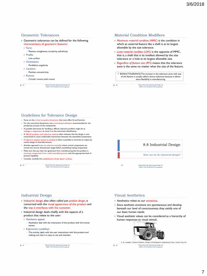
Visual Aesthetics
Aesthetics relate to our emotions.
Since aesthetic emotions are spontaneous and develop
beneath our level of consciousness, they satisfy one of
our basic human needs.
Visual aesthetic values can be considered as a hierarchy of
human responses to visual stimuli.
42 Dieter/Schmidt, Engineering Design 5e.
©2013. The McGraw-Hill Companies
Z. M. Lewalski, Product Esthetics, Design & Development Engineering Press, Carson City, NV.
3/6/2018
8
8.9 Human Factors Design
What is human factors design?
43 Dieter/Schmidt, Engineering Design 5e.
©2013. The McGraw-Hill Companies
Human Factors Design
Human factors is the study of the interaction between people,
the products and systems they use, and the environments in
which they work and live.
This field also is described by the terms human factors
engineering and ergonomics.
Human factors design applies information about human
characteristics to the creation of objects, facilities, and
environments that people use.
Human factors expertise is found in industrial designers, who
focus on ease of use of products, and in industrial engineers,
who focus on design of production systems for productivity.
44 Dieter/Schmidt, Engineering Design 5e.
©2013. The McGraw-Hill Companies
Human Physical Effort
Measurement of the physical effort that a man could
perform in the manual handling of materials (shoveling
coal) and supplies was one of the first studies made in
human factors engineering.
45
Correspondence Between Human Factors Characteristics & Product Performance
Dieter/Schmidt, Engineering Design 5e.
©2013. The McGraw-Hill Companies
Sensory Input
The human senses of sight, touch, hearing, taste, and smell
are chiefly used for purposes of controlling devices or
systems.
In selecting visual displays remember that individuals differ
in their ability to see, so provide sufficient illumination.
Different types of visual displays differ in their ability to
provide on-off information, or exact values and rate of
change information.
46 Dieter/Schmidt, Engineering Design 5e.
©2013. The McGraw-Hill Companies
Muscle Strength of Arm, Hand, Thumb
47 Dieter/Schmidt, Engineering Design 5e.
©2013. The McGraw-Hill Companies
MIL-STD-1472F, p. 95.
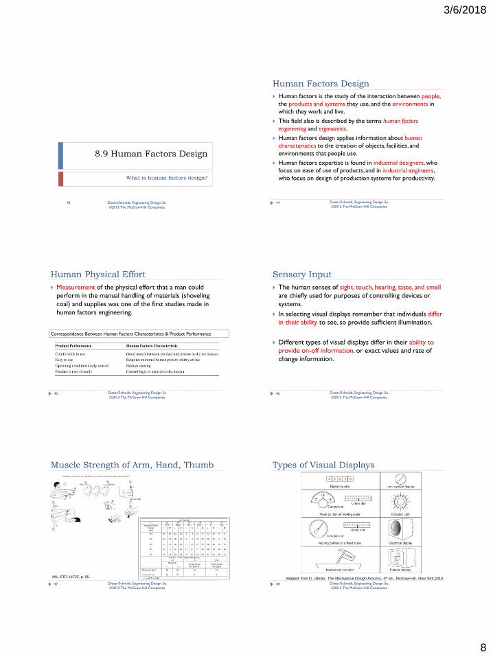
Types of Visual Displays
48 Dieter/Schmidt, Engineering Design 5e.
©2013. The McGraw-Hill Companies
Adapted from D. Ullman, The Mechanical Design Process, 4th ed., McGraw-Hill, New York,2010.
3/6/2018
9
Characteristics of Common Visual
Displays
49 Dieter/Schmidt, Engineering Design 5e.
©2013. The McGraw-Hill Companies
Adapted from D. Ullman, The Mechanical Design Process, 4th ed., McGraw-Hill, New York, 2010.
User-Friendly Design
Simplify Tasks
Make the controls and their functions obvious
Make controls easy to use
Match the intentions of the human with the actions
required by the system
Use mapping
Displays should be clear, visible, large enough to ready
easily, and consistent in direction
Provide feedback
Utilize constraints to prevent incorrect action
Standardize
50 Dieter/Schmidt, Engineering Design 5e.
©2013. The McGraw-Hill Companies
Reaction Time
The reaction time is the time to initiate a response when a
sensory signal has been received.
The reaction time is made up of several actions.
We receive information in the form of a sensory signal,
interpret it in the form of a set of choices, predict the
outcomes of each choice, evaluate the consequence of
each choice, and then select the best choice.
51 Dieter/Schmidt, Engineering Design 5e.
©2013. The McGraw-Hill Companies
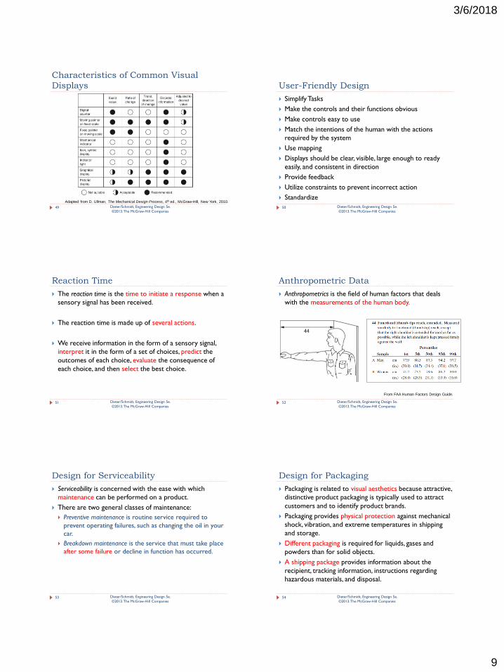
Anthropometric Data
Anthropometrics is the field of human factors that deals
with the measurements of the human body.
52 Dieter/Schmidt, Engineering Design 5e.
©2013. The McGraw-Hill Companies
From FAA Human Factors Design Guide.
Design for Serviceability
Serviceability is concerned with the ease with which
maintenance can be performed on a product.
There are two general classes of maintenance:
Preventive maintenance is routine service required to
prevent operating failures, such as changing the oil in your
car.
Breakdown maintenance is the service that must take place
after some failure or decline in function has occurred.
53 Dieter/Schmidt, Engineering Design 5e.
©2013. The McGraw-Hill Companies
Design for Packaging
Packaging is related to visual aesthetics because attractive,
distinctive product packaging is typically used to attract
customers and to identify product brands.
Packaging provides physical protection against mechanical
shock, vibration, and extreme temperatures in shipping
and storage.
Different packaging is required for liquids, gases and
powders than for solid objects.
A shipping package provides information about the
recipient, tracking information, instructions regarding
hazardous materials, and disposal.
54 Dieter/Schmidt, Engineering Design 5e.
©2013. The McGraw-Hill Companies
3/6/2018
10
8.10 Life-Cycle Design
What is life-cycle design?
55 Dieter/Schmidt, Engineering Design 5e.
©2013. The McGraw-Hill Companies
Life-Cycle Design
The worldwide concern over global warming coupled
with concerns over energy supply and stability have
moved design for the environment (DFE) to a top
consideration in design for all types of engineering
systems and consumer products.
The major issues of life-cycle design are:
Design for packaging and shipping
Design for serviceability and maintenance
Design for testability
Design for disposal
56 Dieter/Schmidt, Engineering Design 5e.
©2013. The McGraw-Hill Companies
8.11 Prototyping and Testing
How can we do prototyping and testing?
57 Dieter/Schmidt, Engineering Design 5e.
©2013. The McGraw-Hill Companies
Prototype & Model Testing Throughout
the Design Process
Phase Zero:
Product Concept Model
Conceptual Design:
Proof-of Concept Prototype
Embodiment Design:
Alpha-Prototype Testing
Detail Design:
Beta-Prototype Testing
Manufacturing:
Preproduction Prototype Testing
58 Dieter/Schmidt, Engineering Design 5e.
©2013. The McGraw-Hill Companies
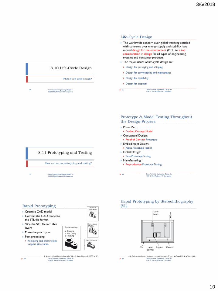
Rapid Prototyping
Create a CAD model
Convert the CAD model to
the STL file format
Slice the STL file into thin
layers
Make the prototype
Post processing:
Removing and cleaning any
support structures.
59 Dieter/Schmidt, Engineering Design 5e.
©2013. The McGraw-Hill Companies
R. Noorani, Rapid Prototyping, John Wiley & Sons, New York, 2006, p. 37.
Rapid Prototyping by Stereolithography
(SL)
60 Dieter/Schmidt, Engineering Design 5e.
©2013. The McGraw-Hill Companies
J. A. Schey, Introduction to Manufacturing Processes, 3rd ed., McGraw-Hill, New York, 2000.
3/6/2018
11
RP Processes
Stereolithography (SL):
This process uses a UV laser beam to build up layers of solid polymer by
scanning on the surface of a bath of photosensitive polymer.
Selective laser sintering (SLS):
This process was developed to use stronger, higher-melting-temperature
materials than polymers in the RP process.
Laminated Object Modeling (LOM):
This process is an older method that continues to have useful applications
because of the simplicity of the equipment that is needed.
Fused-Deposition Modeling (DFM):
This process is an example of several liquid-state deposition processes used to
make prototypes.
Three-dimensional Printing (3DP):
This process is a RP process that is based on the principle of the inkjet printer.
61 Dieter/Schmidt, Engineering Design 5e.
©2013. The McGraw-Hill Companies
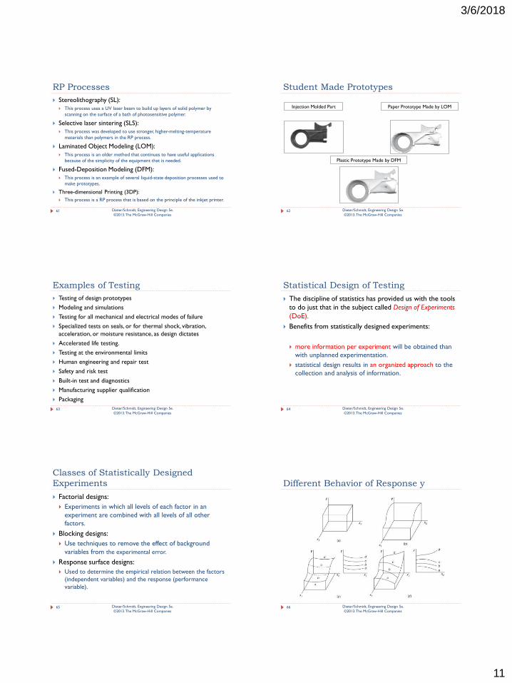
Student Made Prototypes
62
Injection Molded Part Paper Prototype Made by LOM
Plastic Prototype Made by DFM
Dieter/Schmidt, Engineering Design 5e.
©2013. The McGraw-Hill Companies
Examples of Testing
Testing of design prototypes
Modeling and simulations
Testing for all mechanical and electrical modes of failure
Specialized tests on seals, or for thermal shock, vibration,
acceleration, or moisture resistance, as design dictates
Accelerated life testing.
Testing at the environmental limits
Human engineering and repair test
Safety and risk test
Built-in test and diagnostics
Manufacturing supplier qualification
Packaging
63 Dieter/Schmidt, Engineering Design 5e.
©2013. The McGraw-Hill Companies
Statistical Design of Testing
The discipline of statistics has provided us with the tools
to do just that in the subject called Design of Experiments
(DoE).
Benefits from statistically designed experiments:
more information per experiment will be obtained than
with unplanned experimentation.
statistical design results in an organized approach to the
collection and analysis of information.
64 Dieter/Schmidt, Engineering Design 5e.
©2013. The McGraw-Hill Companies
Classes of Statistically Designed
Experiments
Factorial designs:
Experiments in which all levels of each factor in an
experiment are combined with all levels of all other
factors.
Blocking designs:
Use techniques to remove the effect of background
variables from the experimental error.
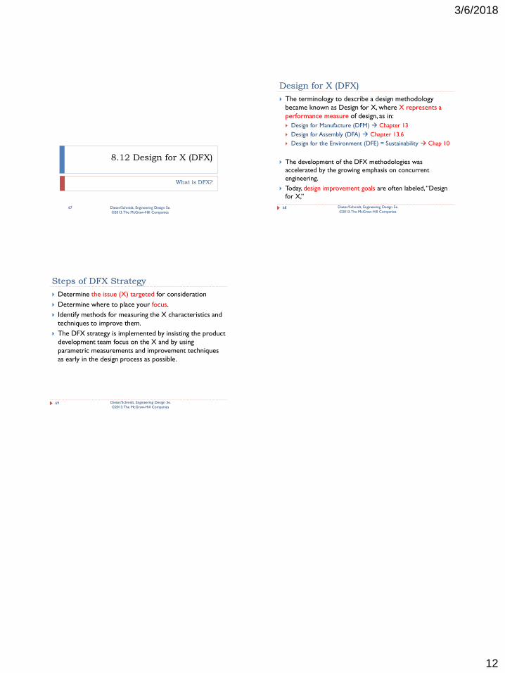
Response surface designs:
Used to determine the empirical relation between the factors
(independent variables) and the response (performance
variable).
65 Dieter/Schmidt, Engineering Design 5e.
©2013. The McGraw-Hill Companies
Different Behavior of Response y
66 Dieter/Schmidt, Engineering Design 5e.
©2013. The McGraw-Hill Companies
3/6/2018
12
8.12 Design for X (DFX)
What is DFX?
67 Dieter/Schmidt, Engineering Design 5e.
©2013. The McGraw-Hill Companies
Design for X (DFX)
The terminology to describe a design methodology
became known as Design for X, where X represents a
performance measure of design, as in:
Design for Manufacture (DFM) Chapter 13
Design for Assembly (DFA) Chapter 13.6
Design for the Environment (DFE) = Sustainability Chap 10
The development of the DFX methodologies was
accelerated by the growing emphasis on concurrent
engineering.
Today, design improvement goals are often labeled, “Design
for X,”
68 Dieter/Schmidt, Engineering Design 5e.
©2013. The McGraw-Hill Companies
Steps of DFX Strategy
Determine the issue (X) targeted for consideration
Determine where to place your focus.
Identify methods for measuring the X characteristics and
techniques to improve them.
The DFX strategy is implemented by insisting the product
development team focus on the X and by using
parametric measurements and improvement techniques
as early in the design process as possible.
69 Dieter/Schmidt, Engineering Design 5e.
©2013. The McGraw-Hill Companies