Embed Size (px)
Citation preview
USARAK Pamphlet 750-5
UNITED STATES ARMY ALASKA
Maintenance of Supplies and Equipment
Swingfire Heater Operation, Organizational Repair Parts, and Care and Maintenance Procedures
(National Stock Number 2990-01-202-4128)
United States/Army Alaska Pamphlet 750-5 15 September 1996
*United States Army Alaska Pamphlet 750-5
__________________ *This pamphlet supersedes 6th Infantry Division (Light) Pamphlet 750-5, dated 14 December 1990.
DEPARTMENT OF THE ARMY HEADQUARTERS, UNITED STATES ARMY ALASKA
Fort Richardson, Alaska 99505-5000
United States Army Alaska Pamphlet 750-5 15 September 1996
Maintenance of Supplies and Equipment
Swingfire Heater Operation, Organizational Repair Parts and Care Procedures
Summary. This pamphlet concerning the Swingfire heater has been revised. This pamphlet covers Swingfire usage for the United States Army Alaska (USARAK). This pamphlet has been revised to reflect the change to USARAK.
Applicability. This pamphlet applies to the active Army and the United States Army Reserve.
Impact on New Manning System. This pamphlet does not contain information that effects the New Manning System.
Supplementation. Supplementation of this pamphlet is prohibited without prior approval from the Directorate of Logistics, Maintenance Division, APVR-RDL-M.
Interim changes. Interim changes to this pamphlet are not official unless they are authenticated by the director of information management. Users will destroy interim changes on their expiration dates unless sooner superseded or rescinded.
Suggested improvements. Users are invited to send comments and suggested improvements on Department of the Army (DA) Form 2028 (Recommended Changes to Publications and Blank Forms) directly to APVR-RDL-M.
Contents
Paragraph Page
Chapter 1 Introduction General ............................................................................................1-1.........................1-1 References ......................................................................................1-2.........................1-1 Explanation of term..........................................................................1-3.........................1-2 Material source ................................................................................1-4.........................1-2
Chapter 2 Operating Instructions Foreword..........................................................................................2-1.........................2-1 Safety training..................................................................................2-2.........................2-1 Operations .......................................................................................2-3.........................2-1 Preventive maintenance checks and services ................................2-4.........................2-1 Malfunctions ....................................................................................2-5.........................2-1 Repair parts and rapair part support................................................2-6.........................2-1 Maintenance allocation chart ...........................................................2-7.........................2-1 Publications .....................................................................................2-8.........................2-2 Basic issue items.............................................................................2-9.........................2-2 Storage ..........................................................................................2-10.........................2-2
USARAK Pamphlet 750-2
Paragraph Page
ii
Technical Data...............................................................................2-11.........................2-2
Appendixes A. Operation .................................................................................................................. A-1 B. Preventive Maintenance Checks and Services......................................................... B-1 C. Maintenance Instructions—Troubleshooting.............................................................C-1 D. Repair Parts ..............................................................................................................D-1 E. Basic Issue Items...................................................................................................... E-1
USARAK Pamphlet 750-5
1-1
Chapter 1 Introduction
1-1. General
a. Scope. This pamphlet covers Swingfire heater operation, organizational maintenance, and lists repair parts for use within USARAK.
b. Forms and records. Use equipment forms and records Defense Department (DD) Form 314 (Equipment Maintenance Log (Consolidated)), DA Form 2408-14 (Uncorrected Fault Record), DA Form 2404 (Equipment Inspection and Maintenance Worksheet) and DA Form 2408-9 (Equipment Control Record) to record actions associated with the Swingfire heater (transfer, gain and loss, etc.).
1-2. References
a. Related publications. (Related publications are merely sources of further information. The user does not have to read them to understand this pamphlet.)
(1) DA Pamphlet 738-750 (Functional Users Manual for the Army Maintenance Management System (TAMMS)).
(2) TM 9-2320-266-34P (Direct and General Support Maintenance Repair Parts and Special Tools List for Truck, Cargo: 1 1/4-ton, 4X4, M880 (NSN 2320-00-579-8942) M881 w/28 V, 60 Ampere Generating System Kit (2320-00-579-8943); M882 w/28 V, 60 Ampere Generating System and Communications Kits (2320-00-579-8957); M883 w/28 V, 60 Ampere Generating System and Communications Kits (2320-00-579-8957); M883 w28 V, 60 Ampere Generating System and S250 Shelter Kits (2320-00-579-8959); M884 w/28 V, 100 Ampere Generating System and S250 Shelter Kits (2320-00-579-8985); M885 w/S250 Shelter Kit (2320-00-579-8989); Truck, Cargo: 1 1/4-Ton, 4X2, M890 (2320-00-579-8991); M891 w/28 V, 60 Ampere Generating System Kit (2320-00-579-9046); M892 w/28 V, 60 Ampere Generating System and Communications Kits (2320-00-579-9052); Truck, Ambulance: 1 1/4-Ton, Truck, Chassis: 1 1/4-Ton, 4X4, M887 (2320-00-579-9080); 1 1/4-Ton, 4X2, M893 (2310-00-125-5679) and Truck, Telephone Maintenance: 1 1/4-Ton, 4X4, M888 (2320-01-044-0333).
b. Referenced forms
(1) DA Form 348 (Equipment Operator's Qualification Record). Cited in paragraph 2-2.
(2) DA Form 2028 (Recommended Changes to Publications and Blank Forms). Cited in the suggested improvements statement.
(3) DA Form 2404 (Equipment Inspection and Maintenance Worksheet). Cited in paragraph 1-1b.
(4) DA Form 2408-9 (Equipment Control Record). Cited in paragraph 1-1b.
(5) DA Form 2408-14 (Uncorrected Fault Record). Cited in paragraph 1-1b.
USARAK Pamphlet 750-2
1-2
(6) Defense Department (DD) Form 314 (Equipment Maintenance Log (Consolidated)). Cited in paragraph 1-1b.
(7) Optional Form (OF) 346 (U.S. Government Motor Vehicle Operator's Identification Card). Cited in paragraph 2-2.
1-3. Explanation of terms
a. DA......................... Department of the Army
b. DC......................... direct current
c. DD......................... Defense Department
d. fig .......................... figure
e. FSCM.................... Federal Supply Codes for Manufacturers
f. NSN ....................... national stock number
g. OF......................... Optional Form
h. SMR...................... source, maintenance, and recoverability
i. TAMMS.................. The Army Maintenance Management System
j. TM.......................... Technical Manual
k. U.S. ....................... United States
l. USARAK ................ United States Army Alaska
1-4. Material source
Material for this pamphlet was compiled from data that was published in TM 9-2320-266-34P and TMs that are no longer available through the Army Publication System.
USARAK Pamphlet 750-5
2-1
Chapter 2 Operating Instructions
2-1. Foreword
The Swingfire heater is the primary means of preheating equipment during extreme cold weather. Swingfire heater systems, installed on equipment, permit vehicle operation in extreme cold weather conditions. The Swingfire preheating system consists of two major components: 1) the heat exchange and hardware that is installed on the vehicle, and 2) the Swingfire heater. Swingfire heater usage aids vehicle starting even if it is cold-soaked down to -50 degrees Fahrenheit. The Swingfire heater, manufactured by J. Eberspacher of West Germany, is used to preheat vehicle engine coolant in extreme cold conditions. The heater runs on gasoline; leaded, unleaded, or aviation type fuel the heater. A 12- or 24-volt direct current (DC) outlet is installed on equipment to permit initial starting, after which the heater works by self-ignition in the combustion chamber. In addition to engine preheating, the Swingfire heater can be used to warm vehicle components, such as the differential transfer, road wheels, and tires. It is also used to keep water from freezing in water trailers.
2-2. Safety training
The Swingfire heater is fuel burning equipment that requires special handling. Swingfire heater operators must be properly trained on heater operation and the system mounted on the equipment. The exhaust fumes from the Swingfire heater are POISONOUS. They must not be allowed to enter a closed room inhabited by personnel. Enter training data on DA Form 348 (Equipment Operator's Qualification Record) and Optional Form (OF) 346 (U.S. Government Motor Vehicle Operator's Identification Card).
2-3. Operations
See appendix A for operational instructions.
2-4. Preventive maintenance checks and services
Preventive maintenance checks and services are covered in appendix B.
2-5. Malfunctions
Common malfunctions that you may find during Swingfire heater operation or maintenance are found in appendix C.
2-6. Repair parts and repair part support
Repair part illustrations and lists are in appendix D. Process all repair parts heater as local purchases.
2-7. Maintenance allocation chart
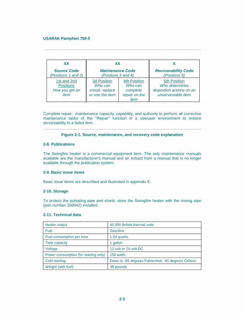
The source, maintenance, and recoverability (SMR) codes listed in table D-1 will be used to determine what level of maintenance will accomplish repairs. The SMR code is a 5-position code containing supply/requisitioning information, maintenance category authorization criteria, and disposition instruction, as shown in figure 2-1.
USARAK Pamphlet 750-5
2-2
_______________________________________________________________________
XX XX X
Source Code (Positions 1 and 2)
Maintenance Code (Postions 3 and 4)
Recoverability Code (Postions 5)
1st and 2nd Positions
How you get an item
3d Position Who can
install, replace or use the item
4th Position Who can complete
repair on the item
5th Position Who determines
dispostion actions on an unserviceable item
Complete repair: maintenance capacity, capability, and authority to perform all corrective maintenance tasks of the "Repair" function in a use/user environment to restore serviceability to a failed item. _______________________________________________________________________
Figure 2-1. Source, maintenance, and recovery code explanation
2-8. Publications
The Swingfire heater is a commercial equipment item. The only maintenance manuals available are the manufacturer's manual and an extract from a manual that is no longer available through the publication system.
2-9. Basic issue items
Basic issue items are described and illustrated in appendix E.
2-10. Storage
To protect the pulsating pipe and shield, store the Swingfire heater with the mixing pipe (part number 269042) installed.
2-11. Technical data
Heater output 40,000 British thermal units Fuel Gasoline Fuel consumption per hour 1.04 quarts Tank capacity 1 gallon Voltage 12-volt or 24-volt DC Power consumption (for starting only) 150 watts Cold starting Down to -65 degrees Fahrenheit; -60 degrees Celsius Weight (with fuel) 35 pounds
USARAK Pamphlet 750-5
2-3
FOR THE COMMANDER OFFICIAL: GREGORY S. DAVIS LTC, IN Chief of Staff //Original Signed// FREDRICK J. LEHMAN LTC, SC Director of Information Management
DISTRIBUTION: C Plus 25 - APVR-RDL-M 25 - APVR-RIM-ASD-PB 5 - MOS Library (Building 600, Fort Richardson) 5 - MOS Library (Army Education Center, Building 21-10 (Fort Wainwright)) 3 - APVR-RIM-ASD-WB 1 - APVR-GPA-AE (MOS Library, Assistant Directorate of Personnel and Community Activities,
Education Branch, Attention: Mr. Mauer) 1 - Commander, United States Army Pacific Command, Attention: APIM-OIR
Fort Shafter, Hawaii 96858-5100

USARAK Pamphlet 750-5
A-1
Appendix A Operation
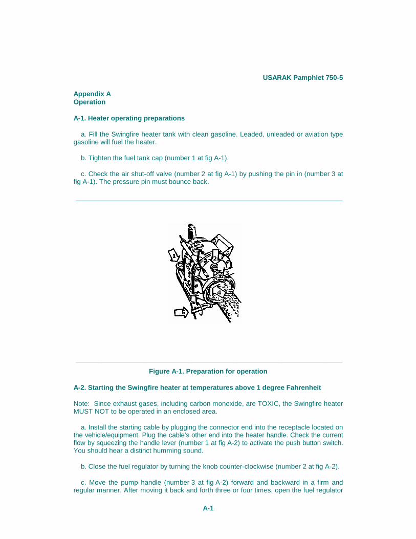
A-1. Heater operating preparations
a. Fill the Swingfire heater tank with clean gasoline. Leaded, unleaded or aviation type gasoline will fuel the heater.
b. Tighten the fuel tank cap (number 1 at fig A-1).
c. Check the air shut-off valve (number 2 at fig A-1) by pushing the pin in (number 3 at fig A-1). The pressure pin must bounce back.
_______________________________________________________________________
_______________________________________________________________________
Figure A-1. Preparation for operation
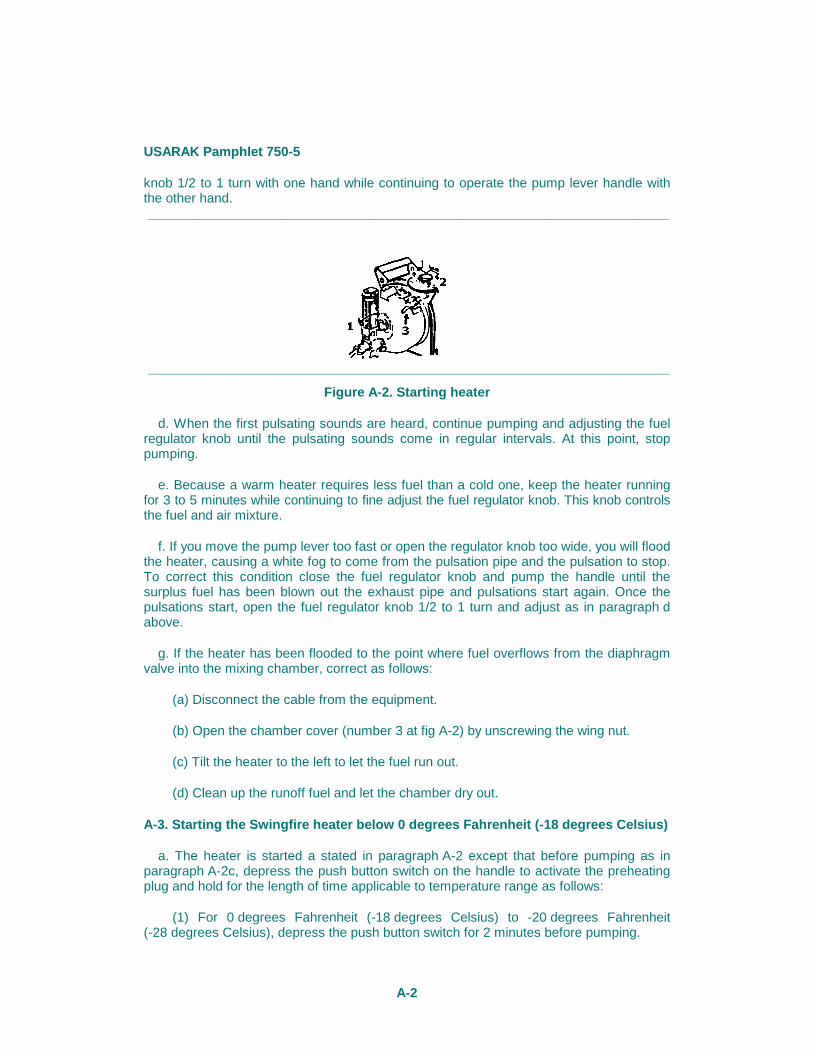
A-2. Starting the Swingfire heater at temperatures above 1 degree Fahrenheit
Note: Since exhaust gases, including carbon monoxide, are TOXIC, the Swingfire heater MUST NOT to be operated in an enclosed area.
a. Install the starting cable by plugging the connector end into the receptacle located on the vehicle/equipment. Plug the cable’s other end into the heater handle. Check the current flow by squeezing the handle lever (number 1 at fig A-2) to activate the push button switch. You should hear a distinct humming sound.
b. Close the fuel regulator by turning the knob counter-clockwise (number 2 at fig A-2).
c. Move the pump handle (number 3 at fig A-2) forward and backward in a firm and regular manner. After moving it back and forth three or four times, open the fuel regulator
USARAK Pamphlet 750-5
A-2
knob 1/2 to 1 turn with one hand while continuing to operate the pump lever handle with the other hand. _______________________________________________________________________
_______________________________________________________________________
Figure A-2. Starting heater
d. When the first pulsating sounds are heard, continue pumping and adjusting the fuel regulator knob until the pulsating sounds come in regular intervals. At this point, stop pumping.
e. Because a warm heater requires less fuel than a cold one, keep the heater running for 3 to 5 minutes while continuing to fine adjust the fuel regulator knob. This knob controls the fuel and air mixture.
f. If you move the pump lever too fast or open the regulator knob too wide, you will flood the heater, causing a white fog to come from the pulsation pipe and the pulsation to stop. To correct this condition close the fuel regulator knob and pump the handle until the surplus fuel has been blown out the exhaust pipe and pulsations start again. Once the pulsations start, open the fuel regulator knob 1/2 to 1 turn and adjust as in paragraph d above.
g. If the heater has been flooded to the point where fuel overflows from the diaphragm valve into the mixing chamber, correct as follows:
(a) Disconnect the cable from the equipment.
(b) Open the chamber cover (number 3 at fig A-2) by unscrewing the wing nut.
(c) Tilt the heater to the left to let the fuel run out.
(d) Clean up the runoff fuel and let the chamber dry out.
A-3. Starting the Swingfire heater below 0 degrees Fahrenheit (-18 degrees Celsius)
a. The heater is started a stated in paragraph A-2 except that before pumping as in paragraph A-2c, depress the push button switch on the handle to activate the preheating plug and hold for the length of time applicable to temperature range as follows:
(1) For 0 degrees Fahrenheit (-18 degrees Celsius) to -20 degrees Fahrenheit (-28 degrees Celsius), depress the push button switch for 2 minutes before pumping.
USARAK Pamphlet 750-5
A-3
(a) For -20 degrees Fahrenheit (-28 degrees Celsius) to -30 degrees Fahrenheit (-36 degrees Celsius), 3 minutes.
(b) For -30 degrees Fahrenheit (-36 degrees Celsius) to -40 degrees Fahrenheit (-40 Celsius), 4 minutes.
(c) For -40 degrees Fahrenheit (-40 degrees Celsius) to -50 degrees Fahrenheit (-46 degrees Celsius), at least 5 minutes.
(2) When starting to pump, as in paragraph A-2b, open the regulator knob 1 to 1 1/2 turns for these low temperatures.
Note: If the heater stops after a long operating period it is probably flooded. Sometimes 10 to 15 pump movements with the regulator valve closed will bring back regular pulsations. The heater cable is not required since the heat from the chamber will ignite the fuel.
A-4. Storing the Swingfire heater after use
a. With the vehicle engine running, turn off the heater by closing the fuel regulator knob completely. Remove the heater from the water jacket.
b. Let the heater cool. Be certain to tighten the heater clamp to the rack retaining tube to prevent damage to the heater when the vehicle is moving. If the heater is not to used for at least 48 hours, let it cool off and remove the remaining gasoline from the heater’s fuel tank.
c. Swingfire heaters placed in storage for the summer months should be stored with the mixing pipe (national stock number (NSN) 2540-12-135-1958) installed to protect the shield that covers the pulsating pipe. Additionally, heaters placed in storage should be in a serviceable condition.

USARAK Pamphlet 750-5
B-1
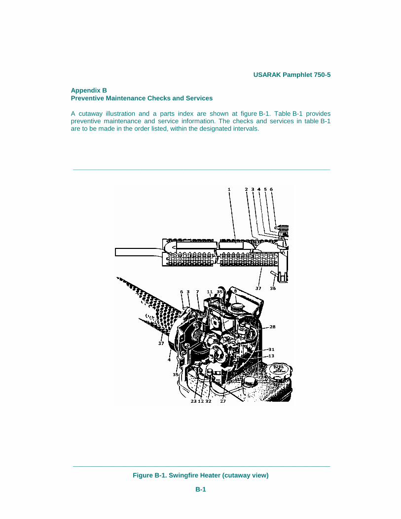
Appendix B Preventive Maintenance Checks and Services
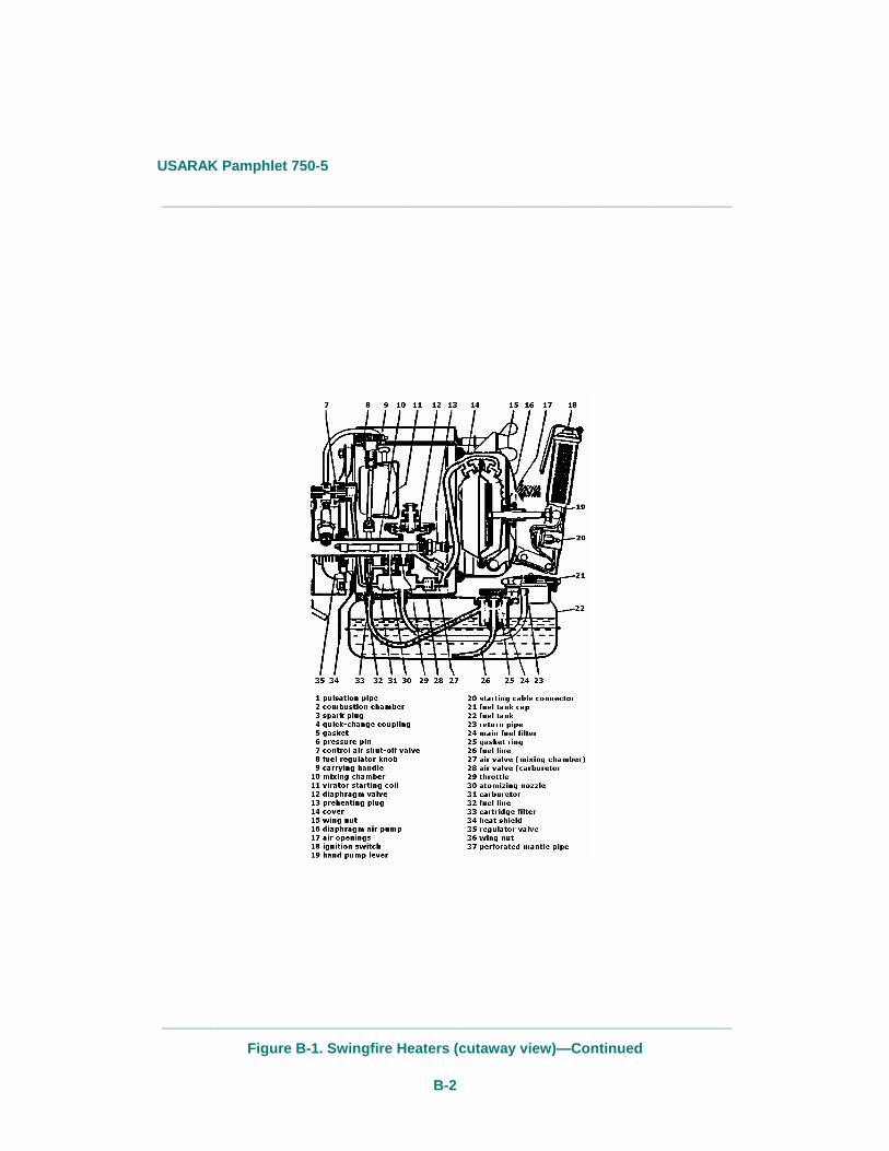
A cutaway illustration and a parts index are shown at figure B-1. Table B-1 provides preventive maintenance and service information. The checks and services in table B-1 are to be made in the order listed, within the designated intervals.
_______________________________________________________________________
_______________________________________________________________________
Figure B-1. Swingfire Heater (cutaway view)
USARAK Pamphlet 750-5
B-2
_______________________________________________________________________
_______________________________________________________________________
Figure B-1. Swingfire Heaters (cutaway view)—Continued
USARAK Pamphlet 750-5
B-3
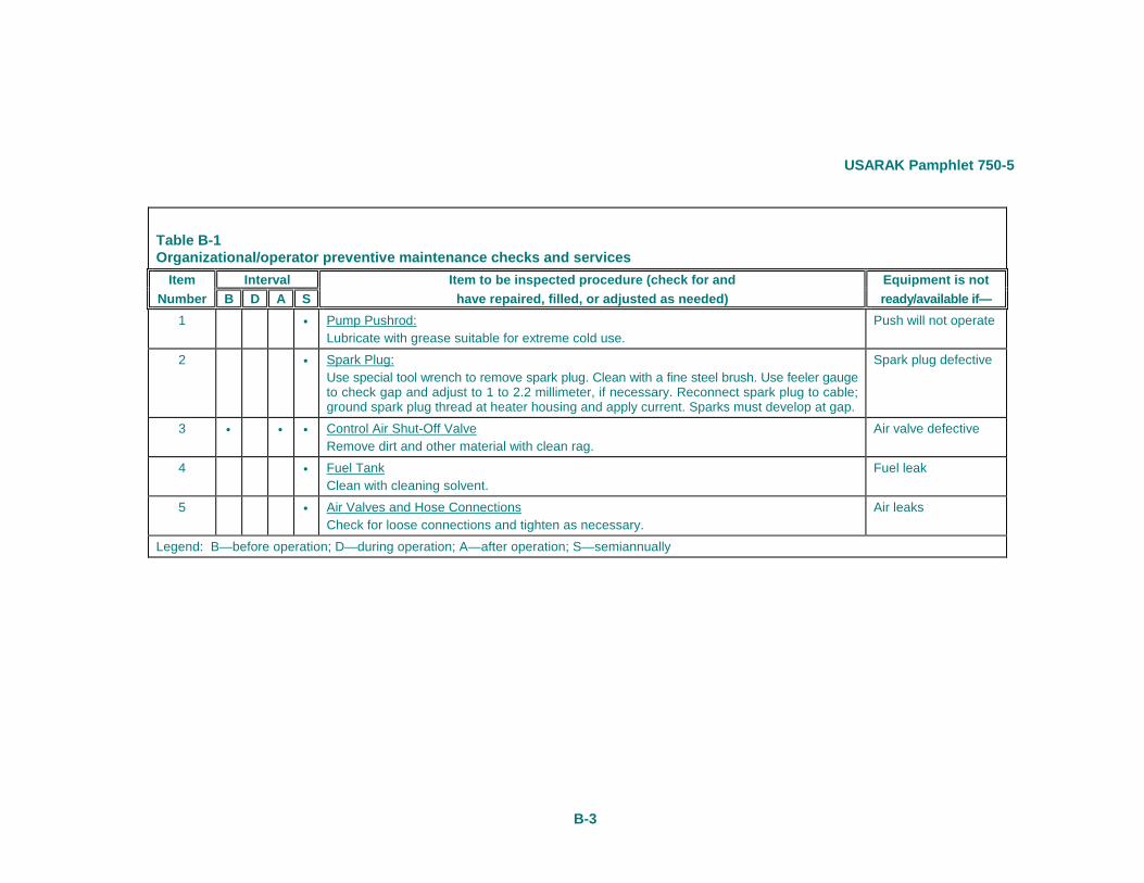
Table B-1 Organizational/operator preventive maintenance checks and services
Item Interval Item to be inspected procedure (check for and Equipment is not Number B D A S have repaired, filled, or adjusted as needed) ready/available if—
1 • Pump Pushrod: Lubricate with grease suitable for extreme cold use.
Push will not operate
2 • Spark Plug: Use special tool wrench to remove spark plug. Clean with a fine steel brush. Use feeler gauge to check gap and adjust to 1 to 2.2 millimeter, if necessary. Reconnect spark plug to cable; ground spark plug thread at heater housing and apply current. Sparks must develop at gap.
Spark plug defective
3 • • • Control Air Shut-Off Valve Remove dirt and other material with clean rag.
Air valve defective
4 • Fuel Tank Clean with cleaning solvent.
Fuel leak
5 • Air Valves and Hose Connections Check for loose connections and tighten as necessary.
Air leaks
Legend: B—before operation; D—during operation; A—after operation; S—semiannually
USARAK Pamphlet 750-5
B-4
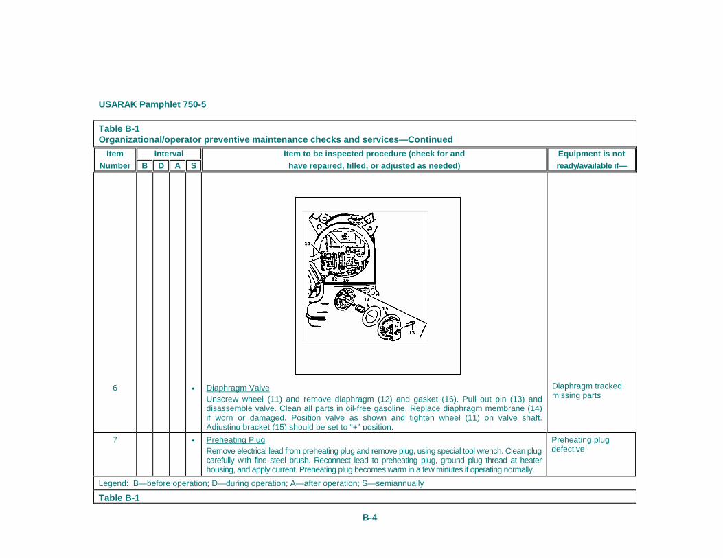
Table B-1 Organizational/operator preventive maintenance checks and services—Continued
Item Interval Item to be inspected procedure (check for and Equipment is not Number B D A S have repaired, filled, or adjusted as needed) ready/available if—
6
•
Diaphragm Valve Unscrew wheel (11) and remove diaphragm (12) and gasket (16). Pull out pin (13) and disassemble valve. Clean all parts in oil-free gasoline. Replace diaphragm membrane (14) if worn or damaged. Position valve as shown and tighten wheel (11) on valve shaft. Adjusting bracket (15) should be set to “+” position.
Diaphragm tracked, missing parts
7 • Preheating Plug Remove electrical lead from preheating plug and remove plug, using special tool wrench. Clean plug carefully with fine steel brush. Reconnect lead to preheating plug, ground plug thread at heater housing, and apply current. Preheating plug becomes warm in a few minutes if operating normally.
Preheating plug defective
Legend: B—before operation; D—during operation; A—after operation; S—semiannually
Table B-1
USARAK Pamphlet 750-5
B-5
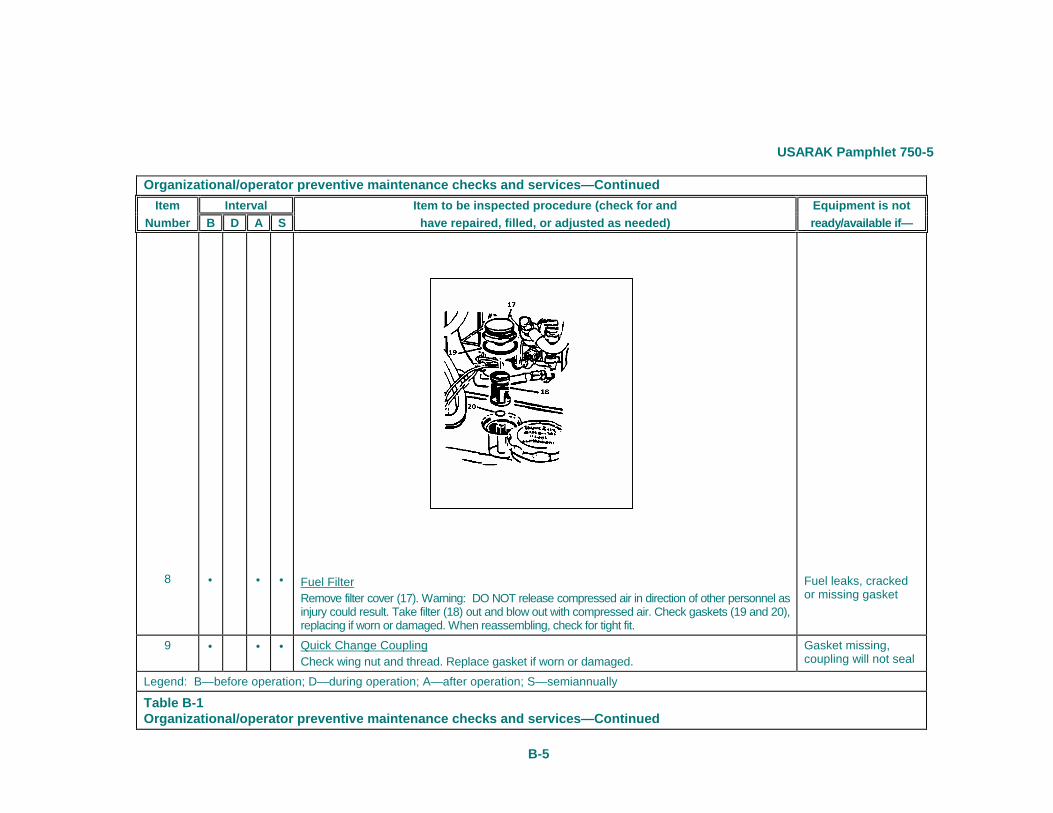
Organizational/operator preventive maintenance checks and services—Continued Item Interval Item to be inspected procedure (check for and Equipment is not
Number B D A S have repaired, filled, or adjusted as needed) ready/available if—
8
•
•
•
Fuel Filter Remove filter cover (17). Warning: DO NOT release compressed air in direction of other personnel as injury could result. Take filter (18) out and blow out with compressed air. Check gaskets (19 and 20), replacing if worn or damaged. When reassembling, check for tight fit.
Fuel leaks, cracked or missing gasket
9 • • • Quick Change Coupling Check wing nut and thread. Replace gasket if worn or damaged.
Gasket missing, coupling will not seal
Legend: B—before operation; D—during operation; A—after operation; S—semiannually
Table B-1 Organizational/operator preventive maintenance checks and services—Continued
USARAK Pamphlet 750-5
B-6
Item Interval Item to be inspected procedNumber B D A S have repaired, filled, or adj
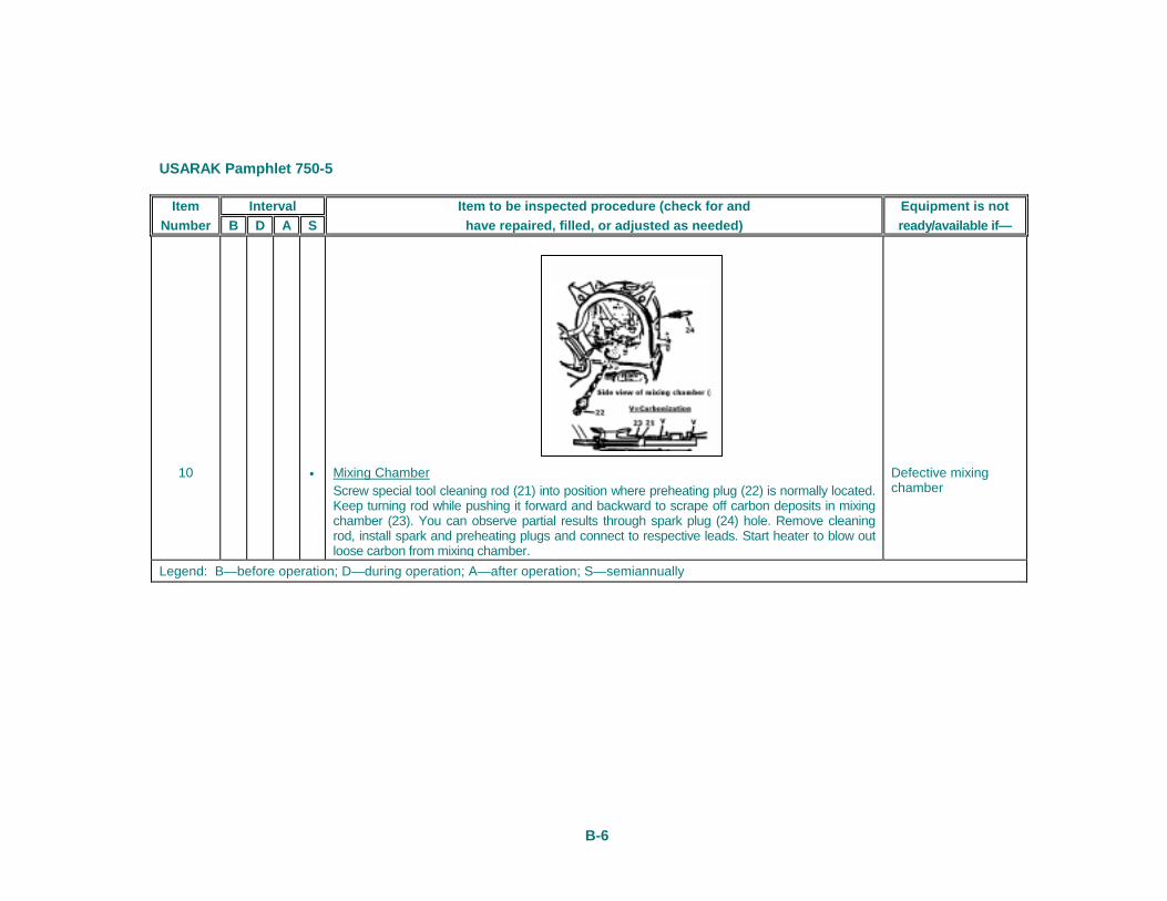
10
•
Mixing Chamber Screw special tool cleaning rod (21) into position wheKeep turning rod while pushing it forward and backwachamber (23). You can observe partial results througrod, install spark and preheating plugs and connect toloose carbon from mixing chamber.
Legend: B—before operation; D—during operation; A—after operation; S—semi
ure (check for and Equipment is not usted as needed) ready/available if—
re preheating plug (22) is normally located. rd to scrape off carbon deposits in mixing h spark plug (24) hole. Remove cleaning respective leads. Start heater to blow out
Defective mixing chamber
annually
USARAK Pamphlet 750-5
C-1
Appendix C Maintenance Instructions—Troubleshooting
Swingfire Heater Troubleshooting
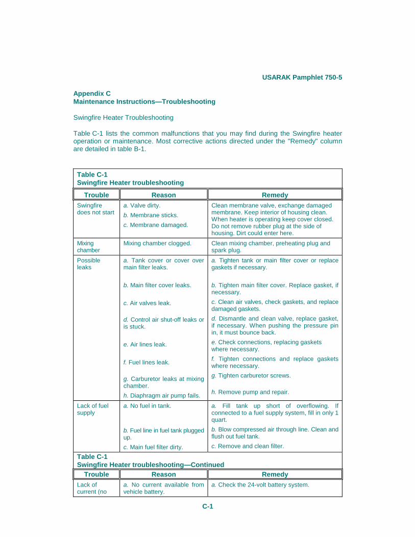
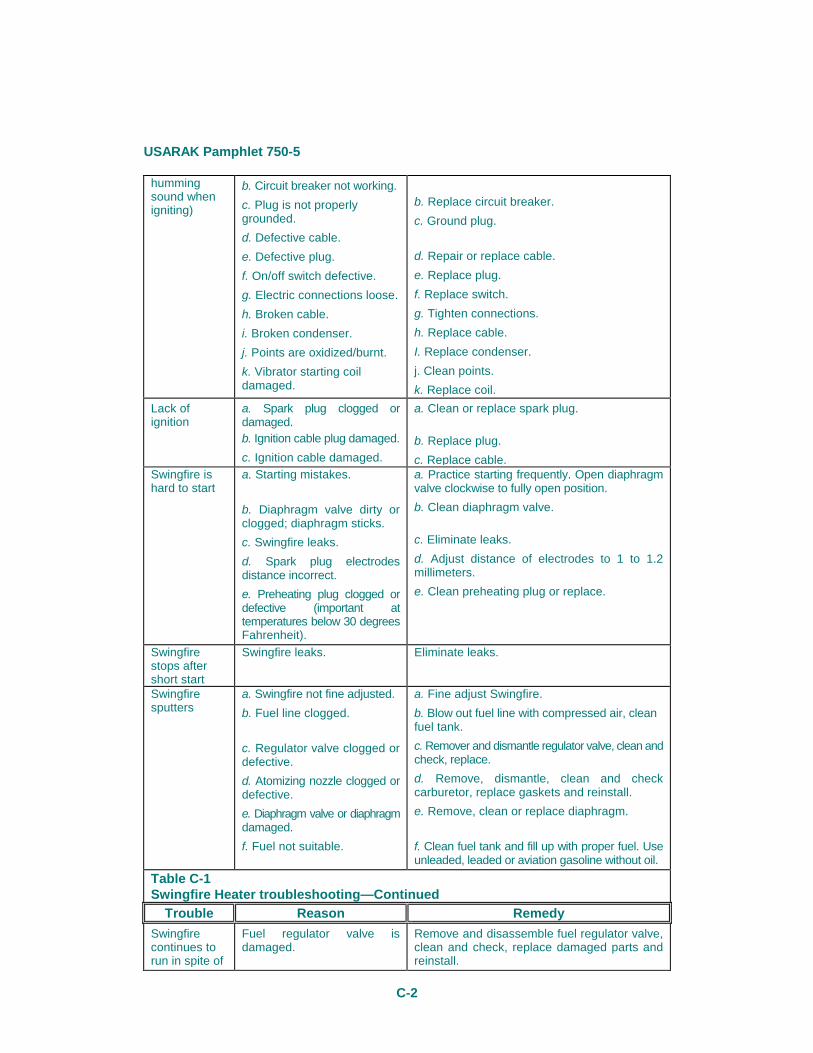
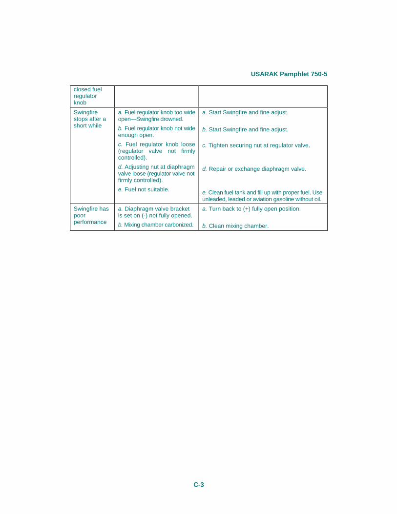
Table C-1 lists the common malfunctions that you may find during the Swingfire heater operation or maintenance. Most corrective actions directed under the "Remedy" column are detailed in table B-1.
Table C-1 Swingfire Heater troubleshooting
Trouble Reason Remedy Swingfire does not start
a. Valve dirty. b. Membrane sticks. c. Membrane damaged.
Clean membrane valve, exchange damaged membrane. Keep interior of housing clean. When heater is operating keep cover closed. Do not remove rubber plug at the side of housing. Dirt could enter here.
Mixing chamber
Mixing chamber clogged. Clean mixing chamber, preheating plug and spark plug.
Possible leaks
a. Tank cover or cover over main filter leaks.
b. Main filter cover leaks.
c. Air valves leak.
d. Control air shut-off leaks or is stuck.
e. Air lines leak.
f. Fuel lines leak.
g. Carburetor leaks at mixing chamber. h. Diaphragm air pump fails.
a. Tighten tank or main filter cover or replace gaskets if necessary.
b. Tighten main filter cover. Replace gasket, if necessary. c. Clean air valves, check gaskets, and replace damaged gaskets. d. Dismantle and clean valve, replace gasket, if necessary. When pushing the pressure pin in, it must bounce back. e. Check connections, replacing gaskets where necessary. f. Tighten connections and replace gaskets where necessary. g. Tighten carburetor screws.
h. Remove pump and repair.
Lack of fuel supply
a. No fuel in tank.
b. Fuel line in fuel tank plugged up. c. Main fuel filter dirty.
a. Fill tank up short of overflowing. If connected to a fuel supply system, fill in only 1 quart. b. Blow compressed air through line. Clean and flush out fuel tank. c. Remove and clean filter.
Table C-1 Swingfire Heater troubleshooting—Continued
Trouble Reason Remedy Lack of current (no
a. No current available from vehicle battery.
a. Check the 24-volt battery system.
USARAK Pamphlet 750-5
C-2
humming sound when igniting)
b. Circuit breaker not working. c. Plug is not properly grounded. d. Defective cable. e. Defective plug. f. On/off switch defective. g. Electric connections loose. h. Broken cable. i. Broken condenser. j. Points are oxidized/burnt. k. Vibrator starting coil damaged.
b. Replace circuit breaker. c. Ground plug.
d. Repair or replace cable. e. Replace plug. f. Replace switch. g. Tighten connections. h. Replace cable. I. Replace condenser. j. Clean points. k. Replace coil.
Lack of ignition
a. Spark plug clogged or damaged. b. Ignition cable plug damaged. c. Ignition cable damaged.
a. Clean or replace spark plug.
b. Replace plug. c. Replace cable.
Swingfire is hard to start
a. Starting mistakes.
b. Diaphragm valve dirty or clogged; diaphragm sticks. c. Swingfire leaks. d. Spark plug electrodes distance incorrect. e. Preheating plug clogged or defective (important at temperatures below 30 degrees Fahrenheit).
a. Practice starting frequently. Open diaphragm valve clockwise to fully open position. b. Clean diaphragm valve.
c. Eliminate leaks. d. Adjust distance of electrodes to 1 to 1.2 millimeters. e. Clean preheating plug or replace.
Swingfire stops after short start
Swingfire leaks. Eliminate leaks.
Swingfire sputters
a. Swingfire not fine adjusted. b. Fuel line clogged.
c. Regulator valve clogged or defective. d. Atomizing nozzle clogged or defective. e. Diaphragm valve or diaphragm damaged. f. Fuel not suitable.
a. Fine adjust Swingfire. b. Blow out fuel line with compressed air, clean fuel tank. c. Remover and dismantle regulator valve, clean and check, replace. d. Remove, dismantle, clean and check carburetor, replace gaskets and reinstall. e. Remove, clean or replace diaphragm.
f. Clean fuel tank and fill up with proper fuel. Use unleaded, leaded or aviation gasoline without oil.
Table C-1 Swingfire Heater troubleshooting—Continued
Trouble Reason Remedy Swingfire continues to run in spite of
Fuel regulator valve is damaged.
Remove and disassemble fuel regulator valve, clean and check, replace damaged parts and reinstall.
USARAK Pamphlet 750-5
C-3
closed fuel regulator knob Swingfire stops after a short while
a. Fuel regulator knob too wide open—Swingfire drowned. b. Fuel regulator knob not wide enough open. c. Fuel regulator knob loose (regulator valve not firmly controlled). d. Adjusting nut at diaphragm valve loose (regulator valve not firmly controlled). e. Fuel not suitable.
a. Start Swingfire and fine adjust.
b. Start Swingfire and fine adjust.
c. Tighten securing nut at regulator valve.
d. Repair or exchange diaphragm valve.
e. Clean fuel tank and fill up with proper fuel. Use unleaded, leaded or aviation gasoline without oil.
Swingfire has poor performance
a. Diaphragm valve bracket is set on (-) not fully opened. b. Mixing chamber carbonized.
a. Turn back to (+) fully open position.
b. Clean mixing chamber.

USARAK Pamphlet 750-5
D-1
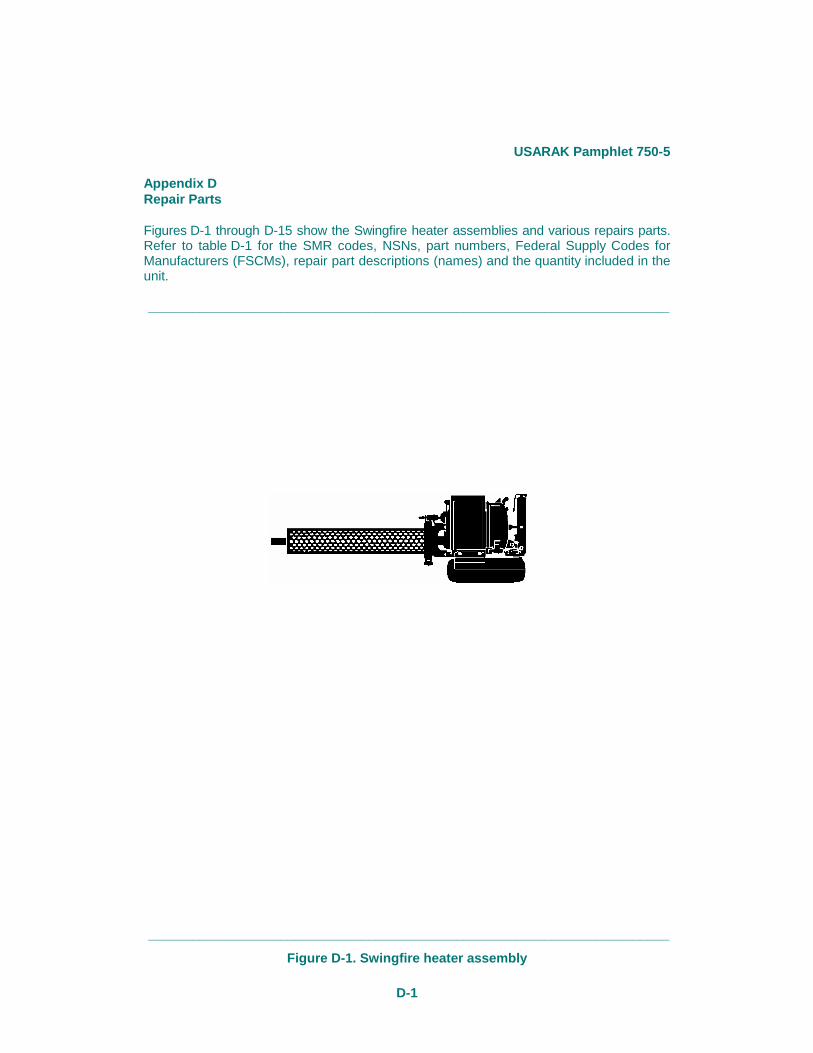
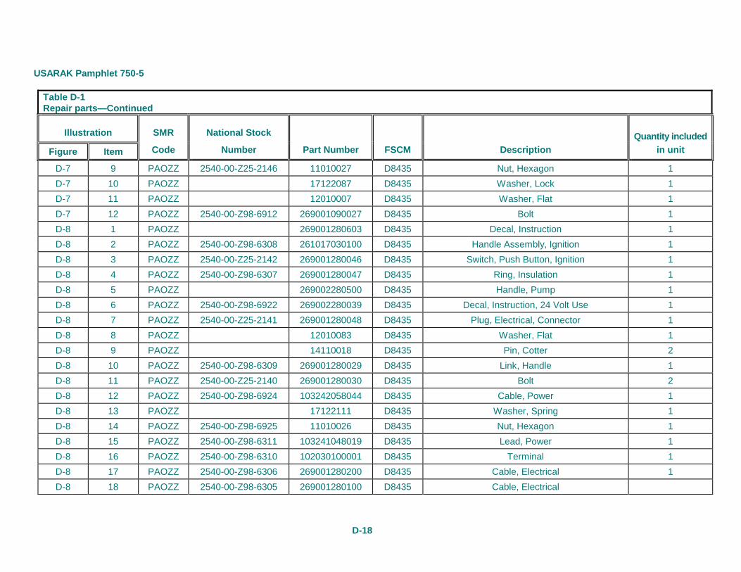
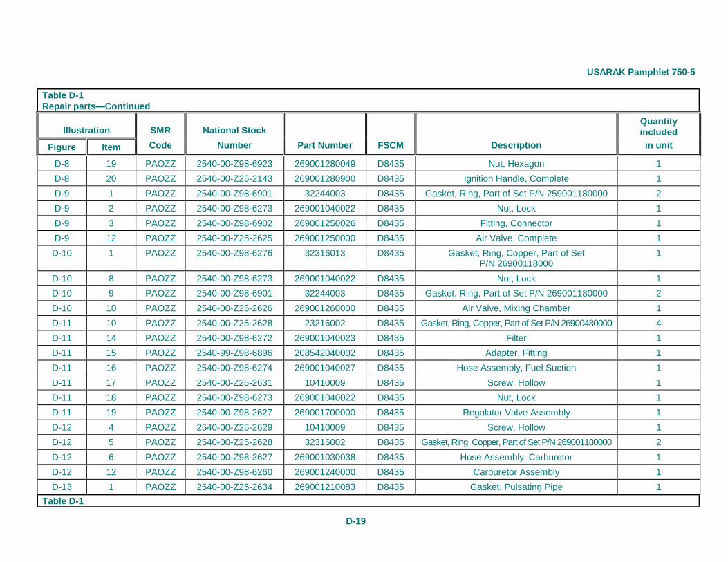
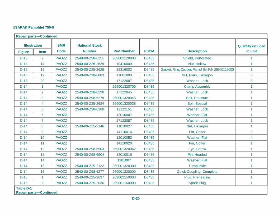
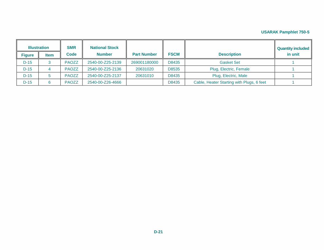
Appendix D Repair Parts
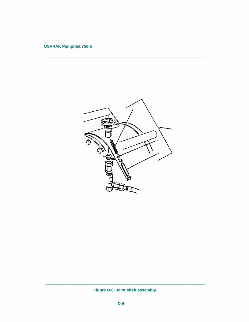
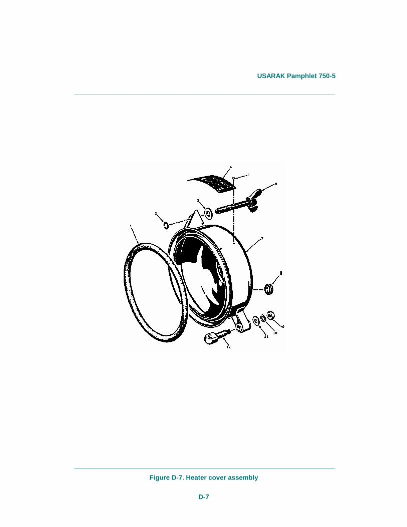
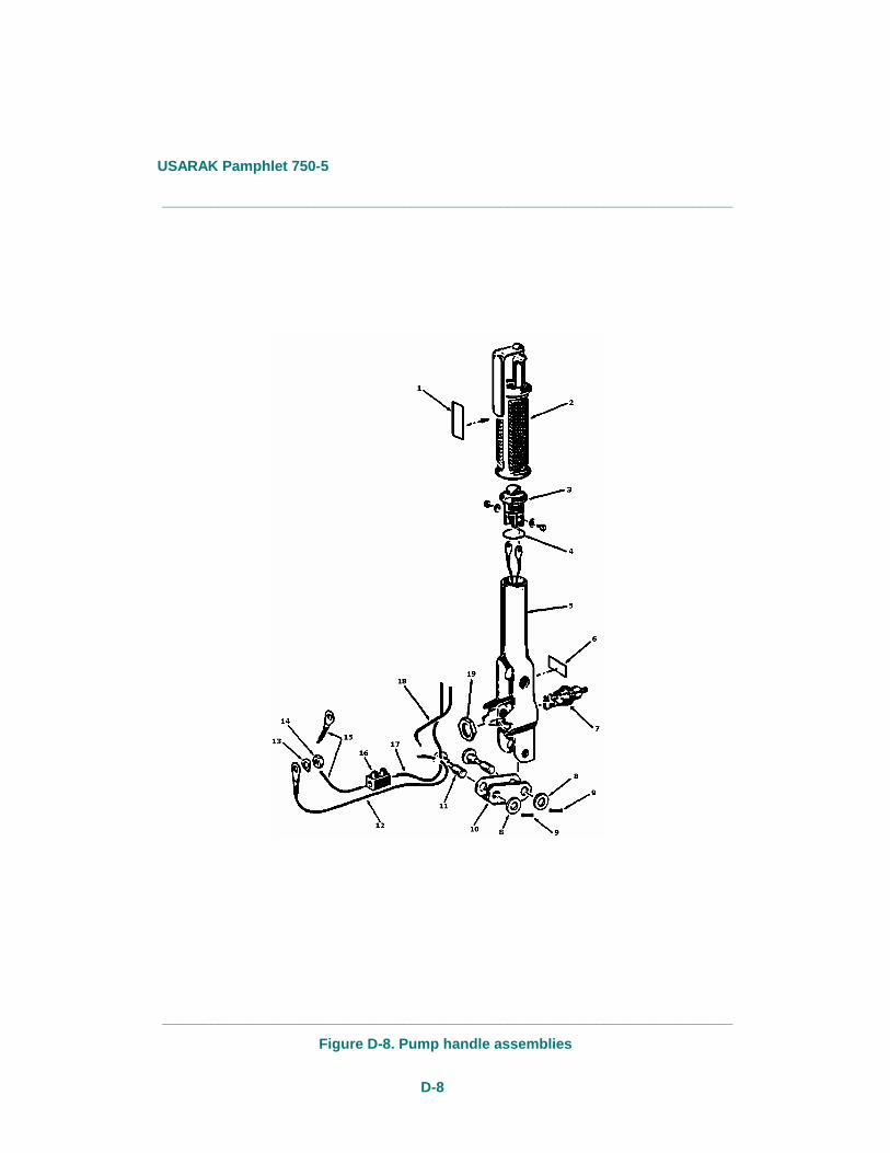
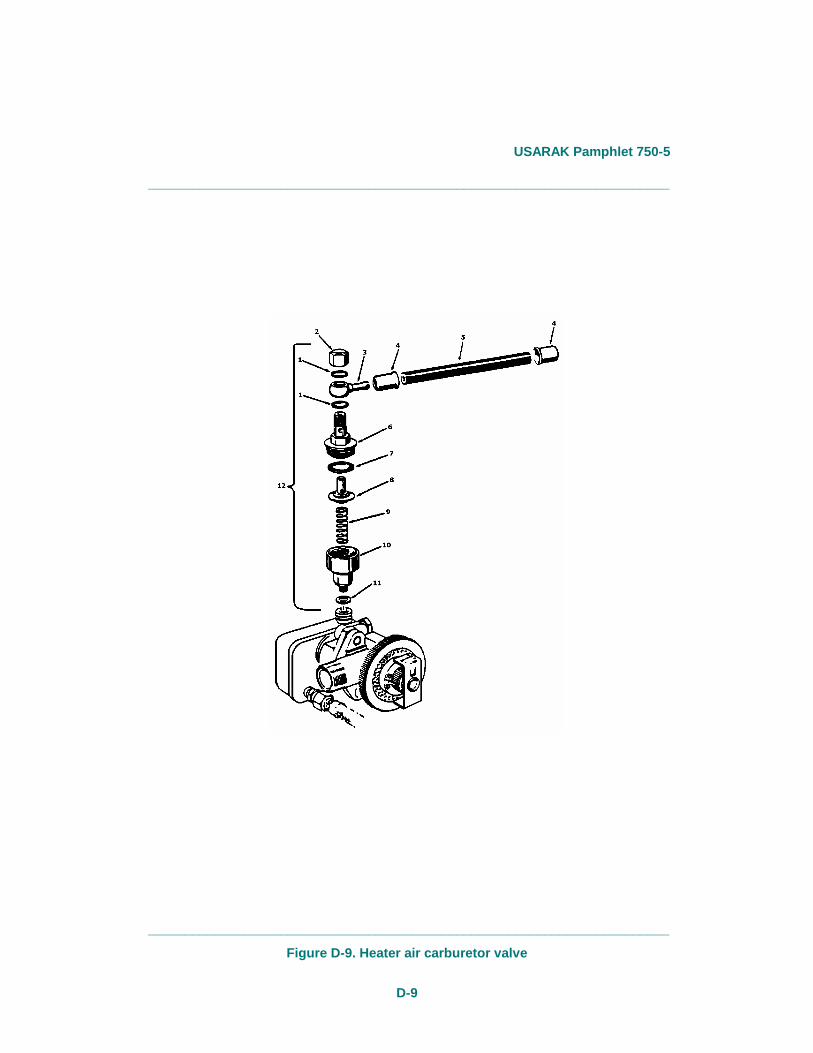
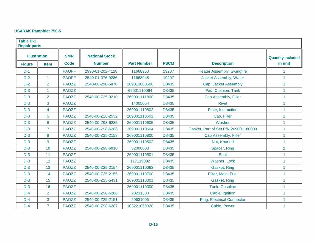
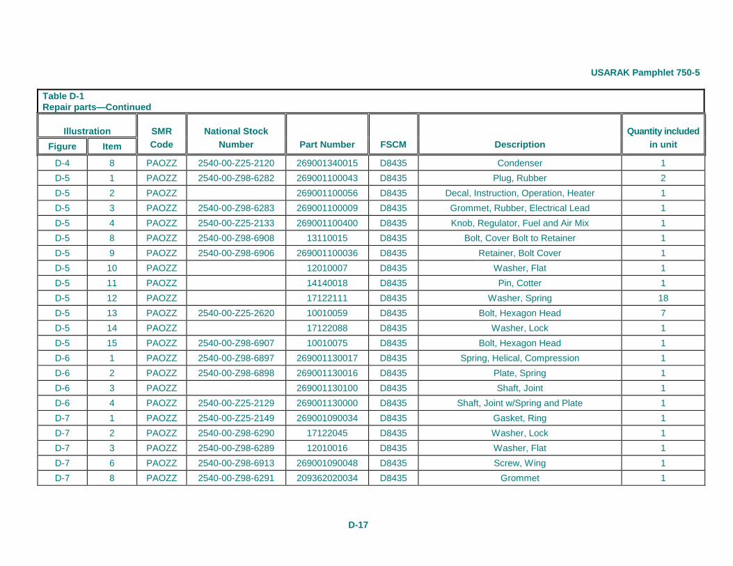
Figures D-1 through D-15 show the Swingfire heater assemblies and various repairs parts. Refer to table D-1 for the SMR codes, NSNs, part numbers, Federal Supply Codes for Manufacturers (FSCMs), repair part descriptions (names) and the quantity included in the unit. _______________________________________________________________________
_______________________________________________________________________
Figure D-1. Swingfire heater assembly
USARAK Pamphlet 750-5
D-2
_______________________________________________________________________
_______________________________________________________________________
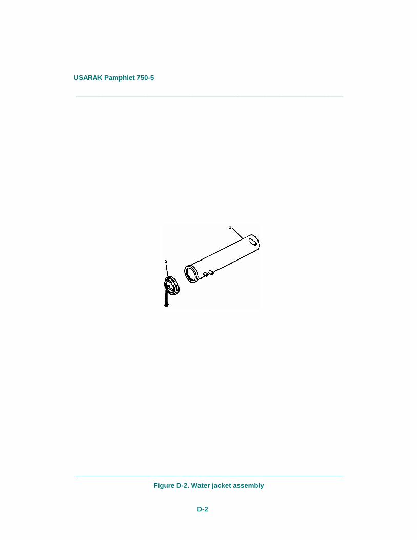
Figure D-2. Water jacket assembly
USARAK Pamphlet 750-5
D-3
_______________________________________________________________________
_______________________________________________________________________
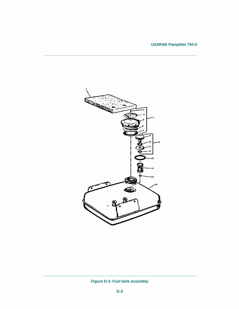
Figure D-3. Fuel tank assembly
USARAK Pamphlet 750-5
D-4
_______________________________________________________________________
_______________________________________________________________________
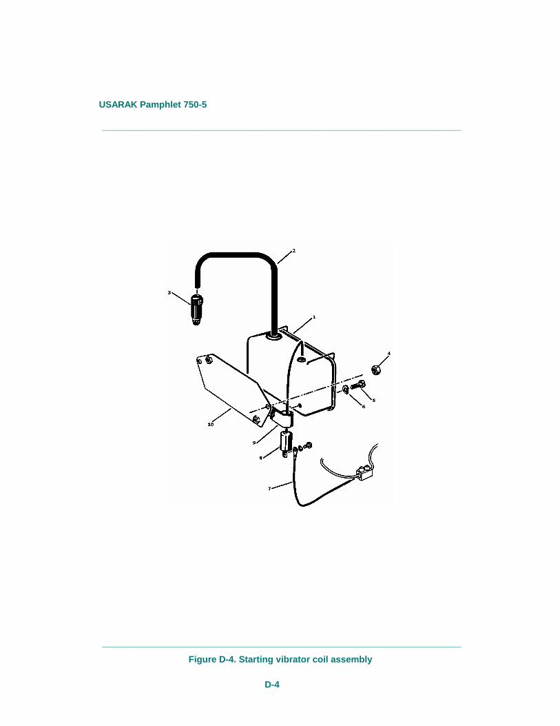
Figure D-4. Starting vibrator coil assembly

USARAK Pamphlet 750-5
D-5
_______________________________________________________________________
_______________________________________________________________________
Figure D-5. Heater housing assembly
USARAK Pamphlet 750-5
D-6
_______________________________________________________________________
_______________________________________________________________________
Figure D-6. Joint shaft assembly
USARAK Pamphlet 750-5
D-7
_______________________________________________________________________
_______________________________________________________________________
Figure D-7. Heater cover assembly
USARAK Pamphlet 750-5
D-8
_______________________________________________________________________
_______________________________________________________________________
Figure D-8. Pump handle assemblies
USARAK Pamphlet 750-5
D-9
_______________________________________________________________________
_______________________________________________________________________
Figure D-9. Heater air carburetor valve
USARAK Pamphlet 750-5
D-10
_______________________________________________________________________
_______________________________________________________________________
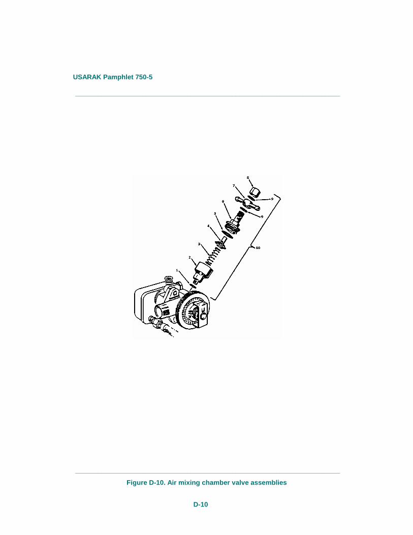
Figure D-10. Air mixing chamber valve assemblies
USARAK Pamphlet 750-5
D-11
_______________________________________________________________________
_______________________________________________________________________
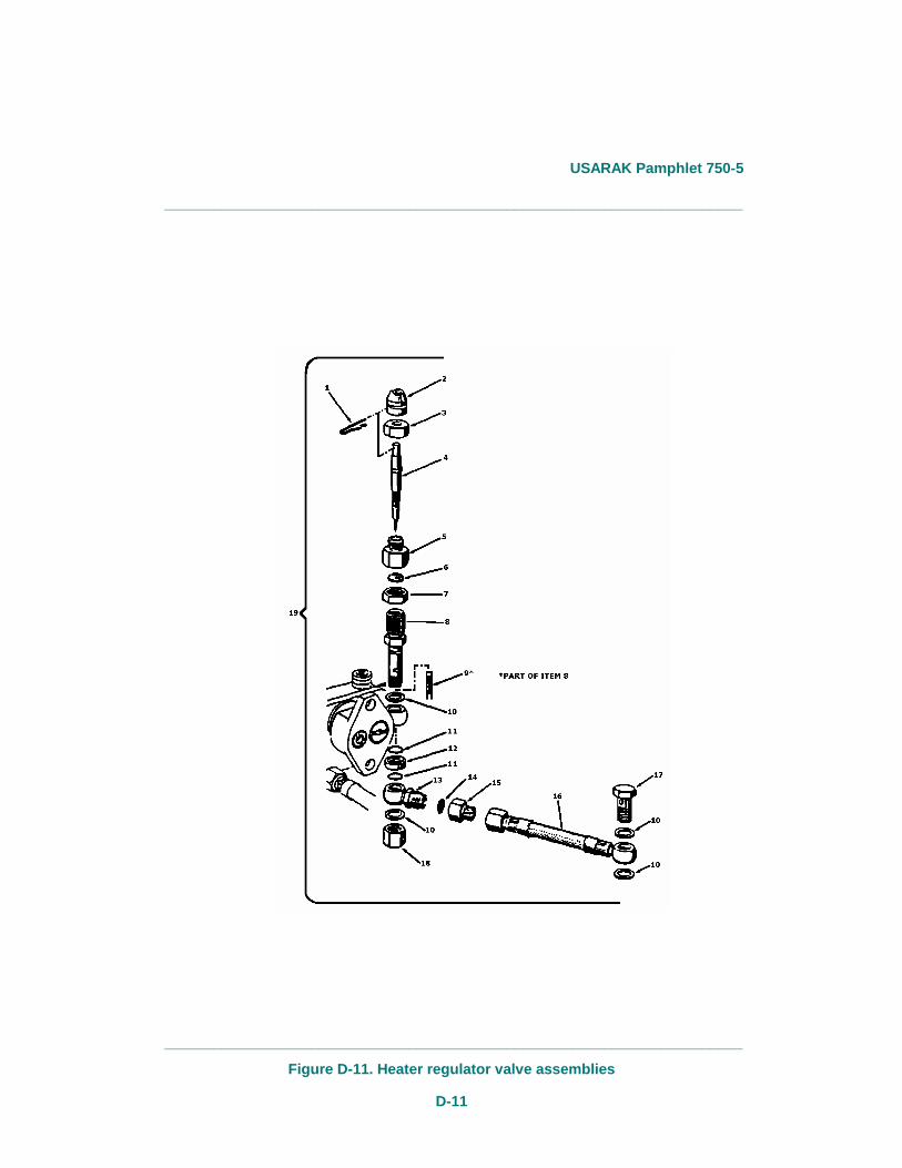
Figure D-11. Heater regulator valve assemblies
USARAK Pamphlet 750-5
D-12
_______________________________________________________________________
_______________________________________________________________________
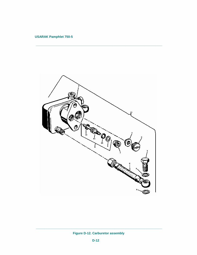
Figure D-12. Carburetor assembly
USARAK Pamphlet 750-5
D-13
_______________________________________________________________________________________________________
_______________________________________________________________________________________________________
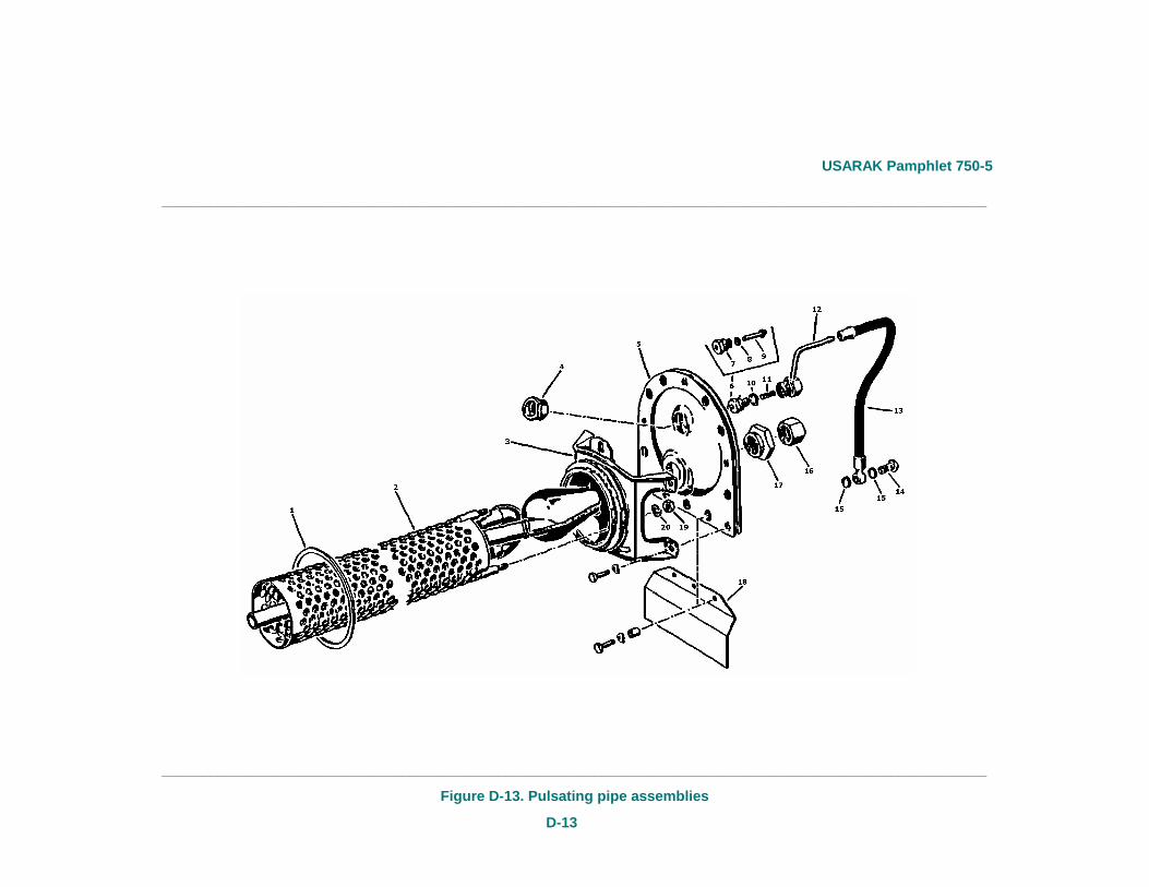
Figure D-13. Pulsating pipe assemblies
USARAK Pamphlet 750-5
D-14
_______________________________________________________________________
_______________________________________________________________________
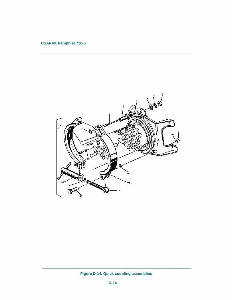
Figure D-14. Quick coupling assemblies
USARAK Pamphlet 750-5
D-15
_______________________________________________________________________
_______________________________________________________________________
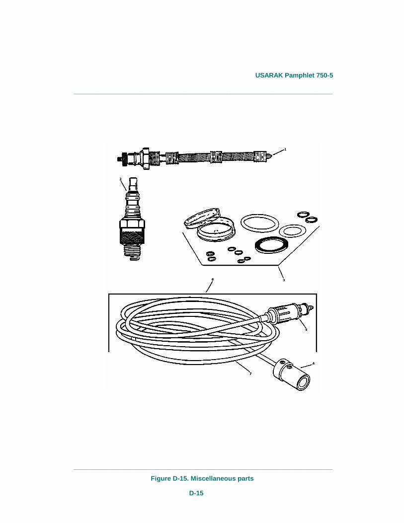
Figure D-15. Miscellaneous parts
USARAK Pamphlet 750-5
D-16
Table D-1 Repair parts
Illustration
SMR
National Stock
Quantity included
Figure Item Code Number Part Number FSCM Description in unit
D-1 PAOFF 2990-01-202-4128 11668950 19207 Heater Assembly, Swingfire 1 D-2 1 PAOFF 2540-01-076-9286 11668948 19207 Jacket Assembly, Water 1 D-2 2 PAOZZ 2540-00-298-6876 269013000600 D8435 Cap, Jacket Assembly 1 D-3 1 PAOZZ 69001110064 D8435 Pad, Cushion, Tank 1 D-3 2 PAOZZ 2540-00-Z25-3210 269001111800 D8435 Cap Assembly, Filler 1 D-3 3 PAOZZ 14005054 D8435 Rivet 1 D-3 4 PAOZZ 269001110802 D8435 Plate, Instruction 1 D-3 5 PAOZZ 2540-00-Z26-2532 269001110601 D8435 Cap, Filler 1 D-3 6 PAOZZ 2540-00-Z98-6285 269001110605 D8435 Washer 1 D-3 7 PAOZZ 2540-00-Z98-6286 269001110604 D8435 Gasket, Part of Set P/N 269001180000 1 D-3 8 PAOZZ 2540-00-Z25-2153 269001110800 D8435 Cap Assembly, Filter 1 D-3 9 PAOZZ 269001110502 D8435 Nut, Knurled 1 D-3 10 PAOZZ 2540-00-Z98-6910 32000003 D8435 Spacer, Ring 2 D-3 11 PAOZZ 269001110501 D8435 Seal 1 D-3 12 PAOZZ 117119082 D8435 Washer, Lock 1 D-3 13 PAOZZ 2540-00-Z25-2154 269001110063 D8435 Gasket, Ring 1 D-3 14 PAOZZ 2540-00-Z25-2155 269001110700 D8435 Filter, Main, Fuel 1 D-3 15 PAOZZ 2540-00-Z25-5431 269001110001 D8435 Gasket, Ring 1 D-3 16 PAOZZ 269001110300 D8435 Tank, Gasoline 1 D-4 2 PAOZZ 2540-00-Z98-6288 20231300 D8435 Cable, Ignition 1 D-4 3 PAOZZ 2540-00-Z25-2151 20631005 D8435 Plug, Electrical Connector 1 D-4 7 PAOZZ 2540-00-Z98-6287 103221059020 D8435 Cable, Power 1
USARAK Pamphlet 750-5
D-17
Table D-1 Repair parts—Continued
Illustration
SMR
National Stock
Quantity included
Figure Item Code Number Part Number FSCM Description in unit
D-4 8 PAOZZ 2540-00-Z25-2120 269001340015 D8435 Condenser 1 D-5 1 PAOZZ 2540-00-Z98-6282 269001100043 D8435 Plug, Rubber 2 D-5 2 PAOZZ 269001100056 D8435 Decal, Instruction, Operation, Heater 1 D-5 3 PAOZZ 2540-00-Z98-6283 269001100009 D8435 Grommet, Rubber, Electrical Lead 1 D-5 4 PAOZZ 2540-00-Z25-2133 269001100400 D8435 Knob, Regulator, Fuel and Air Mix 1 D-5 8 PAOZZ 2540-00-Z98-6908 13110015 D8435 Bolt, Cover Bolt to Retainer 1 D-5 9 PAOZZ 2540-00-Z98-6906 269001100036 D8435 Retainer, Bolt Cover 1 D-5 10 PAOZZ 12010007 D8435 Washer, Flat 1 D-5 11 PAOZZ 14140018 D8435 Pin, Cotter 1 D-5 12 PAOZZ 17122111 D8435 Washer, Spring 18 D-5 13 PAOZZ 2540-00-Z25-2620 10010059 D8435 Bolt, Hexagon Head 7 D-5 14 PAOZZ 17122088 D8435 Washer, Lock 1 D-5 15 PAOZZ 2540-00-Z98-6907 10010075 D8435 Bolt, Hexagon Head 1 D-6 1 PAOZZ 2540-00-Z98-6897 269001130017 D8435 Spring, Helical, Compression 1 D-6 2 PAOZZ 2540-00-Z98-6898 269001130016 D8435 Plate, Spring 1 D-6 3 PAOZZ 269001130100 D8435 Shaft, Joint 1 D-6 4 PAOZZ 2540-00-Z25-2129 269001130000 D8435 Shaft, Joint w/Spring and Plate 1 D-7 1 PAOZZ 2540-00-Z25-2149 269001090034 D8435 Gasket, Ring 1 D-7 2 PAOZZ 2540-00-Z98-6290 17122045 D8435 Washer, Lock 1 D-7 3 PAOZZ 2540-00-Z98-6289 12010016 D8435 Washer, Flat 1 D-7 6 PAOZZ 2540-00-Z98-6913 269001090048 D8435 Screw, Wing 1 D-7 8 PAOZZ 2540-00-Z98-6291 209362020034 D8435 Grommet 1
USARAK Pamphlet 750-5
D-18
Table D-1 Repair parts—Continued
Illustration
SMR
National Stock
Quantity included
Figure Item Code Number Part Number FSCM Description in unit
D-7 9 PAOZZ 2540-00-Z25-2146 11010027 D8435 Nut, Hexagon 1 D-7 10 PAOZZ 17122087 D8435 Washer, Lock 1 D-7 11 PAOZZ 12010007 D8435 Washer, Flat 1 D-7 12 PAOZZ 2540-00-Z98-6912 269001090027 D8435 Bolt 1 D-8 1 PAOZZ 269001280603 D8435 Decal, Instruction 1 D-8 2 PAOZZ 2540-00-Z98-6308 261017030100 D8435 Handle Assembly, Ignition 1 D-8 3 PAOZZ 2540-00-Z25-2142 269001280046 D8435 Switch, Push Button, Ignition 1 D-8 4 PAOZZ 2540-00-Z98-6307 269001280047 D8435 Ring, Insulation 1 D-8 5 PAOZZ 269002280500 D8435 Handle, Pump 1 D-8 6 PAOZZ 2540-00-Z98-6922 269002280039 D8435 Decal, Instruction, 24 Volt Use 1 D-8 7 PAOZZ 2540-00-Z25-2141 269001280048 D8435 Plug, Electrical, Connector 1 D-8 8 PAOZZ 12010083 D8435 Washer, Flat 1 D-8 9 PAOZZ 14110018 D8435 Pin, Cotter 2 D-8 10 PAOZZ 2540-00-Z98-6309 269001280029 D8435 Link, Handle 1 D-8 11 PAOZZ 2540-00-Z25-2140 269001280030 D8435 Bolt 2 D-8 12 PAOZZ 2540-00-Z98-6924 103242058044 D8435 Cable, Power 1 D-8 13 PAOZZ 17122111 D8435 Washer, Spring 1 D-8 14 PAOZZ 2540-00-Z98-6925 11010026 D8435 Nut, Hexagon 1 D-8 15 PAOZZ 2540-00-Z98-6311 103241048019 D8435 Lead, Power 1 D-8 16 PAOZZ 2540-00-Z98-6310 102030100001 D8435 Terminal 1 D-8 17 PAOZZ 2540-00-Z98-6306 269001280200 D8435 Cable, Electrical 1 D-8 18 PAOZZ 2540-00-Z98-6305 269001280100 D8435 Cable, Electrical
USARAK Pamphlet 750-5
D-19
Table D-1 Repair parts—Continued
Illustration
SMR
National Stock
Quantity included
Figure Item Code Number Part Number FSCM Description in unit
D-8 19 PAOZZ 2540-00-Z98-6923 269001280049 D8435 Nut, Hexagon 1 D-8 20 PAOZZ 2540-00-Z25-2143 269001280900 D8435 Ignition Handle, Complete 1 D-9 1 PAOZZ 2540-00-Z98-6901 32244003 D8435 Gasket, Ring, Part of Set P/N 259001180000 2 D-9 2 PAOZZ 2540-00-Z98-6273 269001040022 D8435 Nut, Lock 1 D-9 3 PAOZZ 2540-00-Z98-6902 269001250026 D8435 Fitting, Connector 1 D-9 12 PAOZZ 2540-00-Z25-2625 269001250000 D8435 Air Valve, Complete 1 D-10 1 PAOZZ 2540-00-Z98-6276 32316013 D8435 Gasket, Ring, Copper, Part of Set
P/N 26900118000 1
D-10 8 PAOZZ 2540-00-Z98-6273 269001040022 D8435 Nut, Lock 1 D-10 9 PAOZZ 2540-00-Z98-6901 32244003 D8435 Gasket, Ring, Part of Set P/N 269001180000 2 D-10 10 PAOZZ 2540-00-Z25-2626 269001260000 D8435 Air Valve, Mixing Chamber 1 D-11 10 PAOZZ 2540-00-Z25-2628 23216002 D8435 Gasket, Ring, Copper, Part of Set P/N 26900480000 4 D-11 14 PAOZZ 2540-00-Z98-6272 269001040023 D8435 Filter 1 D-11 15 PAOZZ 2540-99-Z98-6896 208542040002 D8435 Adapter, Fitting 1 D-11 16 PAOZZ 2540-00-Z98-6274 269001040027 D8435 Hose Assembly, Fuel Suction 1 D-11 17 PAOZZ 2540-00-Z25-2631 10410009 D8435 Screw, Hollow 1 D-11 18 PAOZZ 2540-00-Z98-6273 269001040022 D8435 Nut, Lock 1 D-11 19 PAOZZ 2540-00-Z98-2627 269001700000 D8435 Regulator Valve Assembly 1 D-12 4 PAOZZ 2540-00-Z25-2629 10410009 D8435 Screw, Hollow 1 D-12 5 PAOZZ 2540-00-Z25-2628 32316002 D8435 Gasket, Ring, Copper, Part of Set P/N 269001180000 2 D-12 6 PAOZZ 2540-00-Z98-2627 269001030038 D8435 Hose Assembly, Carburetor 1 D-12 12 PAOZZ 2540-00-Z98-6260 269001240000 D8435 Carburetor Assembly 1 D-13 1 PAOZZ 2540-00-Z25-2634 269001210083 D8435 Gasket, Pulsating Pipe 1
Table D-1
USARAK Pamphlet 750-5
D-20
Repair parts—Continued
Illustration
SMR
National Stock
Quantity included Figure Item Code Number Part Number FSCM Description in unit
D-13 2 PAOZZ 2540-00-Z98-6251 269002120800 D8435 Shield, Perforated 1 D-13 14 PAOZZ 2540-00-Z25-2629 10410009 D8435 Nut, Hollow 1 D-13 15 PAOZZ 2540-00-Z25-2628 32316002 D8435 Gasket, Ring, Copper, Part of Set P/N 26900118000 1 D-13 19 PAOZZ 2540-00-Z98-6883 11061000 D8435 Nut, Plain, Hexagon 3 D-13 20 PAOZZ 17122087 D8435 Washer, Lock 3 D-14 1 PAOZZ 269001320700 D8435 Clamp Assembly 1 D-14 2 PAOZZ 2540-00-Z98-6290 17122045 D8435 Washer, Lock 1 D-14 3 PAOZZ 2540-00-Z98-6279 269001320045 D8435 Bolt, Pressure 1 D-14 4 PAOZZ 2540-00-Z25-2624 269001320038 D8435 Bolt, Special 1 D-14 5 PAOZZ 2540-00-Z98-6280 12122151 D8435 Washer, Lock 1 D-14 6 PAOZZ 12010007 D8435 Washer, Flat 1 D-14 7 PAOZZ 17122087 D8435 Washer, Lock 1 D-14 8 PAOZZ 2540-00-Z25-2146 11010027 D8435 Nut, Hexagon 1 D-14 9 PAOZZ 14110014 D8435 Pin, Cotter 2 D-14 10 PAOZZ 12010053 D8435 Washer, Flat 4 D-14 11 PAOZZ 14110020 D8435 Pin, Cotter 1 D-14 12 PAOZZ 2540-00-Z98-6903 269001320042 D8435 Eye, Screw 1 D-14 13 PAOZZ 2540-00-Z98-6904 13010016 D8435 Pin, Headed 1 D-14 14 PAOZZ 1201007 D8435 Washer, Flat 1 D-14 15 PAOZZ 2540-00-Z25-2132 269001320300 D8435 Turnbuckle 1 D-14 16 PAOZZ 2540-00-Z98-6277 269001320000 D8435 Quick Coupling, Complete 1 D-15 1 PAOZZ 2540-00-Z25-2637 269002150000 D8435 Plug, Preheating 1 D-15 2 PAOZZ 2540-00-Z25-2636 269001160000 D8435 Spark Plug 1
Table D-1 Repair parts—Continued
USARAK Pamphlet 750-5
D-21
Illustration
SMR
National Stock
Quantity included
Figure Item Code Number Part Number FSCM Description in unit
D-15 3 PAOZZ 2540-00-Z25-2139 269001180000 D8435 Gasket Set 1 D-15 4 PAOZZ 2540-00-Z25-2136 20631020 D8535 Plug, Electric, Female 1 D-15 5 PAOZZ 2540-00-Z25-2137 20631010 D8435 Plug, Electric, Male 1 D-15 6 PAOZZ 2540-00-Z26-4666 D8435 Cable, Heater Starting with Plugs, 6 feet 1

USARAK Pamphlet 750-5
E-1
Appendix E Basic Issue Items
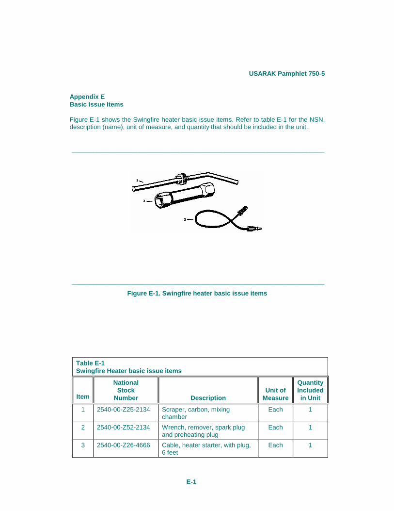
Figure E-1 shows the Swingfire heater basic issue items. Refer to table E-1 for the NSN, description (name), unit of measure, and quantity that should be included in the unit.
_______________________________________________________________________
_______________________________________________________________________
Figure E-1. Swingfire heater basic issue items
Table E-1 Swingfire Heater basic issue items
Item
National Stock
Number
Description
Unit of
Measure
Quantity Includedin Unit
1 2540-00-Z25-2134 Scraper, carbon, mixing chamber
Each 1
2 2540-00-Z52-2134 Wrench, remover, spark plug and preheating plug
Each 1
3 2540-00-Z26-4666 Cable, heater starter, with plug, 6 feet
Each 1