Embed Size (px)
Citation preview
Switch Designa unified view of micro-architecture and circuits
Giorgos Dimitrakopoulos
Electrical and Computer EngineeringDemocritus University of Thrace (DUTH)
Xanthi, Greece
[email protected]://utopia.duth.gr/~dimitrak

Switch Design - NoCs 2012 2
Algorithms-Applications
System abstraction
• Processors for computation• Memories for storage• IO for connecting to the outside world• Network for communication and system integration
Operating System
Instruction Set Architecture
Microarchitecture
Register-Transfer Level
Logic design
Circuits
Devices
Network
Processors Memory
IO
G. Dimitrakopoulos - DUTH

Switch Design - NoCs 2012 3
Logic, State and Memory• Datapath functions
– Controlled by FSMs– Can be pipelined
• Mapped on silicon chips– Gate-level netlist from a cell
library– Cells built from transistors after
custom layout• Memory macros store large
chunks of data– Multi-ported register files for fast
local storage and access of data
G. Dimitrakopoulos - DUTH

Switch Design - NoCs 2012 4
On-Chip Wires
• Passive devices that connect transistors
• Many layers of wiring on a chip• Wire width, spacing
depends on metal layer– High density local
connections, Metal 1-5– Upper metal layers > 6 are
wider and used for less dense low-delay global connections
G. Dimitrakopoulos - DUTH

Switch Design - NoCs 2012 5
Future of wires: 2.5D – 3D integration
Evolution
G. Dimitrakopoulos - DUTH

Switch Design - NoCs 2012 6
Optical wiring
• Optical connections will be integrated on chip – Useful when the power of electrical connections will limit
the available chip IO bandwidth• A balanced solution that involves both optical and
electrical components will probably winG. Dimitrakopoulos - DUTH

Switch Design - NoCs 2012 7
Let’s send a word on a chip
• Sender and receiver on the same clock domain
• Clock-domain crossing just adds latency
• Any relation of the sender-receiver clocks is exploited– Mesochronous interface– Tightly coupled synchronizers
[AMD Zacate]
G. Dimitrakopoulos - DUTH

Switch Design - NoCs 2012 8
Point-to-point links: Flow control
S RData
S RDataValid
S RValid
Stall
Data
• Synchronous operation– Data on every cycle
• Sender can stall– Data valid signal
• Receiver can stall– Stall (back-pressure) signal
• Either can stall – Valid and Stall backpressure– Partially decouple Sender and Receiver by adding a
buffer at the receive side
S RStall
Data
G. Dimitrakopoulos - DUTH
Switch Design - NoCs 2012 9
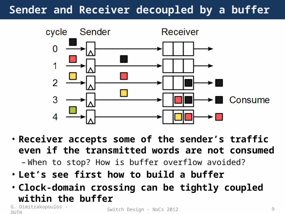
Sender and Receiver decoupled by a buffer
• Receiver accepts some of the sender’s traffic even if the transmitted words are not consumed – When to stop? How is buffer overflow avoided?
• Let’s see first how to build a buffer• Clock-domain crossing can be tightly coupled within the
bufferG. Dimitrakopoulos - DUTH

Switch Design - NoCs 2012 10
Buffer organization
• A FIFO container that maintains order of arrival– 4 interfaces (full, empty, put, get)
• Elastic– Cascade of depth-1 stages – Internal full/empty signals
• Shift register in/Parallel out– Put: shift all entries– Get: tail pointer
• Circular buffer– Memory with head / tail pointers– Wrap around array implementation– Storage can be register based
G. Dimitrakopoulos - DUTH

Switch Design - NoCs 2012 11
Buffer implementation
• The same basic structure evolves with extra read/write flexibility
• Multiplexers and head/tail pointers handle data movement and addressing
Elastic Circular arrayShift In/Parallel Out
G. Dimitrakopoulos - DUTH

Switch Design - NoCs 2012 12
Link-level flow control: Backpressure
• Link-level flow control provides a closed feedback loop to control the flow of data from a sender to a receiver• Explicit flow control (stall-go)
– Receiver notifies the sender when to stop/resume transmission
• Implicit flow control (credits)– Sender knows when to stop to avoid buffer overflow
• For unreliable channels we need extra mechanisms for detecting and handling transmission errors
G. Dimitrakopoulos - DUTH

Switch Design - NoCs 2012 13
STALL-GO flow control
• One signal STALL/GO is sent back to the receiver– STALL=0 (G0) means that the sender is allowed to send – STALL=1 (STALL) means that the sender should stop – The sender changes its behavior the moment it detects a
change to the backpressure signal• Data valid (not shown) is asserted when new data
are available
Stall
G. Dimitrakopoulos - DUTH
Switch Design - NoCs 2012 14
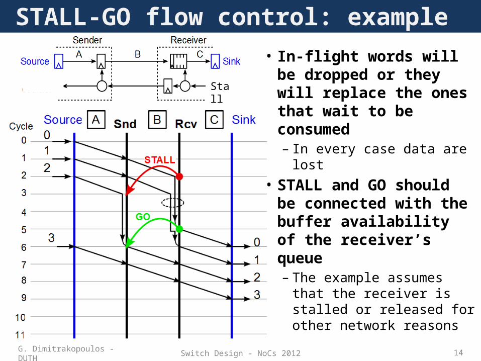
STALL-GO flow control: example
Stall
• In-flight words will be dropped or they will replace the ones that wait to be consumed– In every case data are lost
• STALL and GO should be connected with the buffer availability of the receiver’s queue– The example assumes
that the receiver is stalled or released for other network reasons
G. Dimitrakopoulos - DUTH

Switch Design - NoCs 2012 15
• STALL should be asserted early enough– Not drop words in-flight – Timing of STALL assertion guarantees lossless operation
• GO should be asserted late enough – Have words ready-to-consume before new words arrive– Correct timing guarantees high throughput
• Minimum buffering for full throughput and lossless operation should cover both STALL&GO re-action cycles
Buffering requirements of STALL&GO
Stall
If not available the link remains idle
G. Dimitrakopoulos - DUTH

Switch Design - NoCs 2012 16
STALL&GO on pipelined and elastic links
• Traffic is “blind” during a time interval of Round-trip Time (RTT)– the source will only learn about the effects of its transmission RTT after this
transmission has started– the (corrective) effects of a contention notification will only appear at the
site of contention RTT after that occurrenceG. Dimitrakopoulos - DUTH

Switch Design - NoCs 2012 17
Credit-based flow control
• Sender keeps track of the available buffer slots of the receiver– The number of available slots is called credits – The available credits are stored in a credit counter
• If #credits > 0 sender is allowed to send a new word – Credits are decremented by 1 for each transmitted word
• When one buffer slot is made free in the receive side, the sender is notified to increase the credit count– An example where credit update signal is registered first at the
receive side
G. Dimitrakopoulos - DUTH

Switch Design - NoCs 2012 18
Credit-based flow control: Example
0* means that credit counter is incremented and decremented at the same cycle (ways and stays at 0)
Credit Update
G. Dimitrakopoulos - DUTH
Available Credits

Switch Design - NoCs 2012 19
Credit-based flow control: Buffers and Throughput
G. Dimitrakopoulos - DUTH

Switch Design - NoCs 2012 20
Condition for 100% throughput
• The number of registers that the data and the credits pass through define the credit loop– 100% throughput is guaranteed only when the number of available
buffer slots at the receive side equals the registers of the credit loop• Changing the available number of credits can reconfigure
maximum throughput at runtime– Credit-based FC is lossless with any buffer size > 0.– Stall and Go FC requires at least one loop extra buffer space than
credit-based FC
Credit loop
G. Dimitrakopoulos - DUTH
Switch Design - NoCs 2012 21
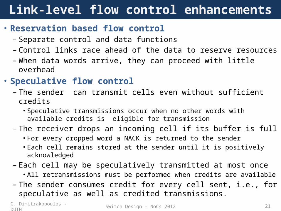
Link-level flow control enhancements• Reservation based flow control
– Separate control and data functions– Control links race ahead of the data to reserve resources– When data words arrive, they can proceed with little overhead
• Speculative flow control– The sender can transmit cells even without sufficient credits
• Speculative transmissions occur when no other words with available credits is eligible for transmission
– The receiver drops an incoming cell if its buffer is full• For every dropped word a NACK is returned to the sender• Each cell remains stored at the sender until it is positively acknowledged
– Each cell may be speculatively transmitted at most once • All retransmissions must be performed when credits are available
– The sender consumes credit for every cell sent, i.e., for speculative as well as credited transmissions.
G. Dimitrakopoulos - DUTH

Switch Design - NoCs 2012 22
Send a large message(packet)
• Send long packet of 1Kbit over a 32-bit-wire channel– Serialize the message to 16
words of 32 bits– Need 16 cycles for packet
transmission• Each packet is transmitted
word-by-word– When the output port is free, send the next
word immediately – Old fashioned Store-and-forward required the
entire packet to reach each node before initiating next transmission
G. Dimitrakopoulos - DUTH

Switch Design - NoCs 2012 23
Buffer allocation policies
• Each transmitted word needs a free downstream buffer slot – When the output of the downstream node is blocked the
buffer will hold the arriving words• How much free buffering is guaranteed before
sending the first word of a packet?– Virtual Cut Through (VCT): The available buffer slots equal
the words of the packet• Each blocked packet stays together and consumes the buffers of
only one node
– Wormhole: Just a few are enough• Packet inevitably occupies the buffers of more nodes • Nothing is lost due to flow control backpressure policy
G. Dimitrakopoulos - DUTH

Switch Design - NoCs 2012 24
VCT and Wormhole in graphics
G. Dimitrakopoulos - DUTH

Switch Design - NoCs 2012 25
Link sharing• The number of wires of the
link does not increase– One word can be sent on each
clock cycle– The channel should be shared
• A multiplexer is needed at the output port of the sender
• Each packet is sent un-interrupted– Wormhole, and VCT behave this way– Connection is locked for a packet
until the tail of the packet passes the output port
G. Dimitrakopoulos - DUTH

Switch Design - NoCs 2012 26
Who drives the select signals?
• The arbiter is responsible for selecting which packet will gain access to the output channel– A word is sent if buffer slots are available downstream
• It receives requests from the inputs and grants only one of them – Decisions are based on some internal priority state
G. Dimitrakopoulos - DUTH

Switch Design - NoCs 2012 27
Arbitration for Wormhole and VCT
• In wormhole and VCT the words of each packet are not mixed with the words of other packets
• Arbitration is performed once per packet and the decision is locked at the output for all packet duration
• Even if a packet is blocked downstream the connection does not change until the tail of the packet leaves the output port– Buffer utilization managed by flow control mechanism
G. Dimitrakopoulos - DUTH

Switch Design - NoCs 2012 28
How can I place my buffers?
G. Dimitrakopoulos - DUTH

Switch Design - NoCs 2012 29
Let’s add some complexity: Networks
• A network of terminal nodes – Each node can be a source or a sink
• Multiple point-to-point links connected with switches• Parallel communication between components
Source/SinkTerminal Node
Switch
G. Dimitrakopoulos - DUTH

Switch Design - NoCs 2012 30
• Multiple input-output permutations should be supported• Contention should be resolved and non-winning inputs should
be handled– Buffered locally– Deflected to the network
• Separate flow control for each link• Each packet needs to know/compute the path to its destination
Complexity affects the switches
G. Dimitrakopoulos - DUTH

Switch Design - NoCs 2012 31
• More than one terminal nodes can connect per switch– Concentration good for bursty traffic – Local switch isolates local traffic from the main network
How are the terminal nodes connected to the switch?
G. Dimitrakopoulos - DUTH

Switch Design - NoCs 2012 32
Switch design: IO interface
Separate flow control per link
G. Dimitrakopoulos - DUTH

Switch Design - NoCs 2012 33
Switch design: One output port
per-output requests
Let’s reuse the circuit we already have for one output port
G. Dimitrakopoulos - DUTH

Switch Design - NoCs 2012 34
• Move buffers to the inputs
Switch design: Input buffers
Data from input#1
Requests for output #0
G. Dimitrakopoulos - DUTH

Switch Design - NoCs 2012 35
Switch design: Complete output ports
• How are the output requests computed?
G. Dimitrakopoulos - DUTH

Switch Design - NoCs 2012 36
Routing computation
• Routing computation generates per output requests– The header of the packet carries the requests for each intermediate
node (source routing)– The requests are computed/retrieved based on the packet’s
destination (distributed routing)G. Dimitrakopoulos - DUTH

Switch Design - NoCs 2012 37
Routing logic
• Routing logic translates a global destination address to a local output port request– To reach node X from node Y
should use output port #2 of Y• A Lookup-table is enough for
holding the request vector that corresponds to each destinationG. Dimitrakopoulos - DUTH

Switch Design - NoCs 2012 38
Switch building blocks
G. Dimitrakopoulos - DUTH

Switch Design - NoCs 2012 39
Running example of switch operation
• Switches transfer packets• Packets are broken to flits
– Head flit only knows packet’s destination • The wires of each link equals the bits of each flitG. Dimitrakopoulos - DUTH

Switch Design - NoCs 2012 40
Buffer access
• Buffer incoming packets per link• Read the destination of the head of each queue
G. Dimitrakopoulos - DUTH
Switch Design - NoCs 2012 41
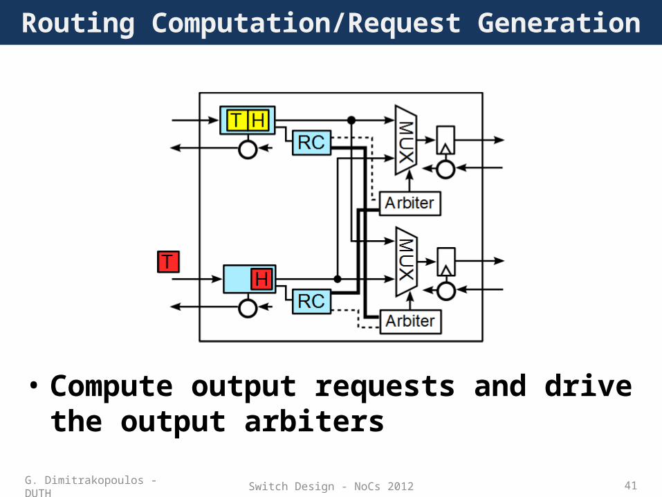
Routing Computation/Request Generation
• Compute output requests and drive the output arbiters
G. Dimitrakopoulos - DUTH

Switch Design - NoCs 2012 42
Arbitration-Multiplexer path setup
• Arbitrate per output• The grant signals
– Drive the output multiplexers– Notify the inputs about the arbitration outcome
G. Dimitrakopoulos - DUTH

Switch Design - NoCs 2012 43
Switch traversal
• Words H will leave the switch on the next clock edge provided they have at least one credit
G. Dimitrakopoulos - DUTH

Switch Design - NoCs 2012 44
Link traversal
• Words going to a non-blocked output leave the switch• The grants of a blocked output (due to flow control) are lost
– An output arbiter can also stall in case of blocked output
G. Dimitrakopoulos - DUTH
Switch Design - NoCs 2012 45
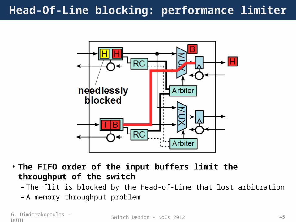
Head-Of-Line blocking: performance limiter
• The FIFO order of the input buffers limit the throughput of the switch– The flit is blocked by the Head-of-Line that lost arbitration– A memory throughput problem
G. Dimitrakopoulos - DUTH

Switch Design - NoCs 2012 46
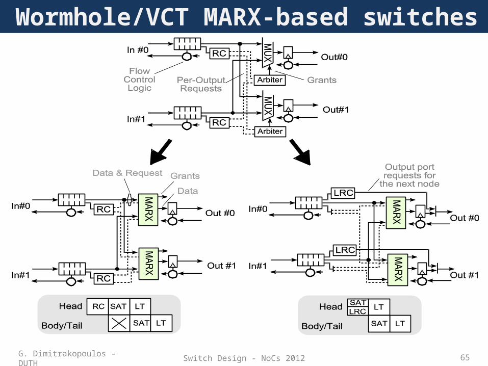
Wormhole switch operation
• The operations can fit in the same cycle or they can be pipelined – Extra registers are needed in the control path– Registers in the input/output ports already present– LT at the end involves a register write
• Body/tail flits inherit the decisions taken by the head flitsG. Dimitrakopoulos - DUTH

Switch Design - NoCs 2012 47
Look-ahead routing
• Routing computation is based only on packet’s destination– Can be performed in switch A and used in switch B
• Look-ahead routing computation (LRC)G. Dimitrakopoulos - DUTH

Switch Design - NoCs 2012 48
Look-ahead routing
• The LRC is performed in parallel to SA• LRC should be completed before the ST stage in
the same switch– The head flit needs the output port requests for the
next switchG. Dimitrakopoulos - DUTH

Switch Design - NoCs 2012 49
Look-ahead routing details
• The head flit of each packet carries the output port requests for the next switch together with the destination address
G. Dimitrakopoulos - DUTH

Switch Design - NoCs 2012 50
Low-latency organizations• Baseline
– SA precedes ST (no speculation)
• SA decoupled from ST– Predict or Speculate arbiter’s decisions– When prediction is wrong replay all the tasks
(same as baseline)
• Do in different phases – Circuit switching– Arbitration and routing at setup phase– At transmit only ST is needed since contention is
already resolved
• Bypass switches– Reduce latency under certain criteria– When bypass not enabled same as baseline
ST
Setup
Xmit
SALRC LT
SA
LRCLTST
STSALRC
ST LT
ST LTG. Dimitrakopoulos - DUTH
LTSetup
Xmit

Switch Design - NoCs 2012 51
Prediction-based ST: Hit
Crossbar
Buffer X+
X-
Y+
Y-
X+
X-
Y+
Y-
PREDICTOR
Crossbar is reserved
Idle state: Output port X+ is selected and reserved1st cycle: Incoming flit is transferred to X+ without RC and SA
Correct
1st cycle: RC is performed The prediction is correct!2nd cycle: Next flit is transferred to X+ without RC and SA
ARBITER
G. Dimitrakopoulos - DUTH

Switch Design - NoCs 2012 52
Prediction-based ST: Miss
X+
X-
Y+
Y-
Idle state: Output port X+ is selected and reserved
Correct
Dead flit
1st cycle: RC is performed The prediction is wrong! (X- is correct)
2nd/3rd cycle: Dead flit is removed; retransmission to the correct port
Buffer X+
X-
Y+
Y-
PREDICTOR ARBITER
1st cycle: Incoming flit is transferred to X+ without RC and SA
KILL
Kill signal to X+ is asserted
Crossbar
@Miss: tasks replayed as the baseline case
G. Dimitrakopoulos - DUTH

Switch Design - NoCs 2012 53
Speculative ST• Assume contention doesn’t happen
– If correct then flit transferred directly to output port without waiting SA
– In case of contention replay SA
• Wasted cycle in the event of contention– Arbiter decides what will be sent
on the next cycle
SwitchFabric
Control
B
AA
clkport 0port 1grantvalid outdata out
0 1 4cycle 2 3
A
p0
A
ABp1
???
B
AA ?
B
A
p0
B A
A
BA
B WinsA Wins
G. Dimitrakopoulos - DUTH

Switch Design - NoCs 2012 54
XOR-based ST
• Assume contention never happens– If correct then flit transferred directly
to output port– If not then bitwise=XOR all the
competing flits and send the encoded result to the link
– At the same time arbitrate and mask (set to 0) the winning input
– Repeat on the next cycle• In the case of contention encoded
outputs (due to contention) are resolved at the receiver– Can be done at the output port of the
switch too
SwitchFabric
Control
B
A
B
AA A^BA
0 1 4cycle 2 3
clkport 0port 1grantvalid outdata out
A
p0
A
ABp1
B^A
A
A
A
No Contention Contention
B Wins
G. Dimitrakopoulos - DUTH

Switch Design - NoCs 2012 55
XOR-based ST: Flit recovery
• Works upon simple XOR property. – (A^B^C) ^ (B^C) = A– Always able to decode by XORing two sequential values
• Performs similarly to speculative switches– Only head-flit collisions matter– Maintains previous router’s arbitration order
Coded
Flit BufferA
A^B^
CB^
C C
A
0
0
B^C
1
A^B^
C
C B^C
B
G. Dimitrakopoulos - DUTH

Switch Design - NoCs 2012 56
Bypassing intermediate nodes
• Switch bypassing criteria:– Frequently used paths – Packets continually moving along the same dimension
• Most techniques can bypass some pipeline stages only for specific packet transfers and traffic patterns– Not generic enough
3-cycle
SRC DST3-cycle 3-cycle
Virtual bypassing paths
3-cycle 3-cycle1-cycle
Bypassed1-cycle
Bypassed
G. Dimitrakopoulos - DUTH

Switch Design - NoCs 2012 57
Circuit switching
G. Dimitrakopoulos - DUTH
• Network traversal done in phases• Path reservation (multiple switch allocations) is done all at
once• Switch traversal finds no contention
– Data buffers are avoided• Part of the reserved and unutilized path is needlessly blocked

Switch Design - NoCs 2012 58
Speculation-free low-latency switches
• Prediction and speculation drawbacks– On miss-prediction(speculation) the tasks should be replayed– Latency not always saved. Depends on network conditions
• Merged Switch allocation and Traversal (SAT)– Latency always saved – no speculation– Delay of SAT smaller than SA and ST in seriesG. Dimitrakopoulos - DUTH

Switch Design - NoCs 2012 59
Arbitration and Multiplexing
• Stop thinking arbitration and multiplexing separately• One new algorithm that fits every policy
– Generic priority-based solution that works even when arbitration and multiplexing are done separately
G. Dimitrakopoulos - DUTH

Switch Design - NoCs 2012 60
Round-robin arbitration
• Round-robin arbitration– Most commonly used– Start from the High-Priority position and grant the first active
request you find after searching all cyclically all requests– Granted input becomes lowest-priority for the next arbitration
• Cyclic search found in many other algorithms
G. Dimitrakopoulos - DUTH

Switch Design - NoCs 2012 61
• Transform each request and priority bit to a 2bit unsigned arithmetic symbol – The request is the MSBit
• Round-robin arbitration is equivalent to finding the maximum symbol that lies in the rightmost position
• Cyclic search disappears
Let’s think out of the box
G. Dimitrakopoulos - DUTH

Switch Design - NoCs 2012 62
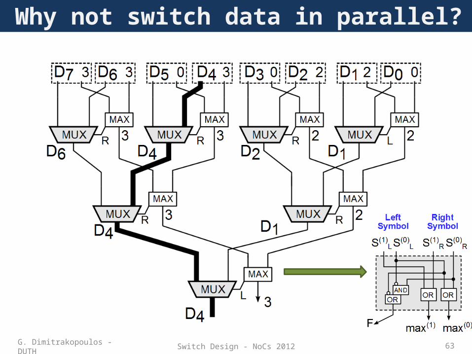
Working examples
• Maximum selection is done via a tree structure– The rightmost maximum symbol always wins
• Direction flags (L,R) always point to the direction of the winning input– Direction flags form the path to the winning input
G. Dimitrakopoulos - DUTH
Switch Design - NoCs 2012 63
Why not switch data in parallel?
G. Dimitrakopoulos - DUTH

Switch Design - NoCs 2012 64
Grant signals produced simultaneously
• When F=0 the maximum came from the Right• When F=1 the maximum came from the Left• Onehot, thermometer, weighted-binary grant signals can
be derived by the tree of MAX nodes
Direction flag F
G. Dimitrakopoulos - DUTH
Switch Design - NoCs 2012 65
Wormhole/VCT MARX-based switches
G. Dimitrakopoulos - DUTH

Switch Design - NoCs 2012 66
SRAM-based input buffers
• Buffer reads and writes are treated as separate tasks– Buffer write occurs always after link traversal
• A separate read and write port is required for maximum performance
G. Dimitrakopoulos - DUTH

Switch Design - NoCs 2012 67
Speculative Buffer Read
• Buffer read occurs after SA for Head flits (no speculation) • Buffer read can occur in parallel to SA (speculation)
– HOL Head flit is read out before knowing if it received a grant– Once SA has finished speculation is removed for the rest flits
G. Dimitrakopoulos - DUTH
Switch Design - NoCs 2012 68
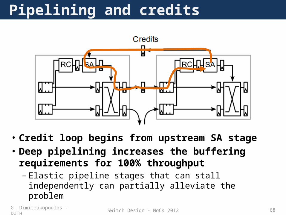
Pipelining and credits
• Credit loop begins from upstream SA stage• Deep pipelining increases the buffering
requirements for 100% throughput– Elastic pipeline stages that can stall independently can
partially alleviate the problemG. Dimitrakopoulos - DUTH

Switch Design - NoCs 2012 69
Bufferless
• Assume there are no buffers– When a packet loses switch allocation it is:
• Dropped• Deflected to any free output
• Deflection spreads contention in space (in the network)– Allocation solves contention at each time slot but
spreads it in time (next time slots)• Deflection (or misrouting) can occur in buffered
switches too– Rotary router
G. Dimitrakopoulos - DUTH

Switch Design - NoCs 2012 70
Slicing
• Introduces hierarchy inside the switch• When traffic is concentrated to certain outputs the
switch suffers high performance penalties• Intermediate buffers partially alleviate the loss
Dimension slicing Port slicing
G. Dimitrakopoulos - DUTH

Switch Design - NoCs 2012 71
How can we increase throughput?
Green flow is blocked until red passes the switch. Physical channel left idle
G. Dimitrakopoulos - DUTH

Switch Design - NoCs 2012 72
• Decouple output port allocation from next-hop buffer allocation• Contention present on:
– Output links (crossbar output port) – Input port of the crossbar
• Contention is resolved by time sharing the resources– Mixing words of two packets on the same channel– The words are on different virtual channels– Separate buffers at the end of the link guarantee no interference
between the packets
Virtual Channels
G. Dimitrakopoulos - DUTH

Switch Design - NoCs 2012 73
Virtual channels
• Virtual-channel support does not mean extra links– They act as extra street lanes – Traffic on each lane is time shared on a common channel
• Provide dedicated buffer space for each virtual channel– Decouple channels from buffers– Interleave flits from different packets
• “The Swiss Army Knife for Interconnection Networks”– Prevent deadlocks– Reduce head-of-line blocking– Provide QoS
G. Dimitrakopoulos - DUTH

Switch Design - NoCs 2012 74
Datapath of a VC-based switch
• Separate buffer for each VC• Separate flow control signals
(credits) for each VC• The radix of the crossbar can
stay the same• Input VCs can share a
common input port of the crossbar– On each cycle at most one VC
will receive a new word
G. Dimitrakopoulos - DUTH

Switch Design - NoCs 2012 75
• A switch connects input VCs to output VCs
• Routing computation (RC) determines the output port– May restrict the output VCs that
can be used • An input VC should allocate
first an output VC– Allocation is performed by the VC
allocator (VA)• RC and VA are done per packet
on the head flits and inherited to the rest flits of the packet
Input VCsOutput VCs
Per-packet operation of a VC-based switch
G. Dimitrakopoulos - DUTH

Switch Design - NoCs 2012 76
Per-flit operation of a VC-based switch
• Flits with an allocated output VC fight for an output port– Output port allocated by switch
allocator– The VCs of the same input share a
common input port of the crossbar– Each input has multiple requests
(equal to the #input VCs)• The flit leaves the switch
provided that credits are available downstream– Credits are counted per output VC
Input VCsOutput VCs
G. Dimitrakopoulos - DUTH

Switch Design - NoCs 2012 77
Switch allocation
• All VCs at a given input port share one crossbar input port
• Switch allocator matches ready-to-go flits with crossbar time slots– Allocation performed on a cycle-by-cycle basis– N×V requests (input VCs), N resources (output ports)– At most one flit at each input port can be granted– At most one flit et each output port can be leave
• Other options need more crossbar ports (input-output speedup)
G. Dimitrakopoulos - DUTH

Switch Design - NoCs 2012 78
Switch allocation example
• One request (arc) for each input VC• Example with 2 VCs per input
– At most 2 arcs leaving each input– At most 2 requests per row in the request matrix
• Matching:– Each grant must satisfy a request– Each requester gets at most one grant– Each resource is granted at most once
Inputs Outputs
00 1 2
21Inputs
Outputs
0
2
1
0
2
1
Bipartite graph Request matrix
G. Dimitrakopoulos - DUTH

Switch Design - NoCs 2012 79
Separable allocation
• Matchings have at most one grant per row and per column
• Two phases of arbitration– Column-wise and row-wise– Perform in either order– Arbiters in each stage are independent
• But the outcome of each one affects the quality of the overall match
• Fast and cheap• Bad choices in first phase can prevent
second stage from generating a good matching– Multiple iterations required for a good match
Input-first:
Output-first:
G. Dimitrakopoulos - DUTH

Switch Design - NoCs 2012 80
Implementation
G. Dimitrakopoulos - DUTH
Output first allocation
Input first allocation

Switch Design - NoCs 2012 81
Multi-cycle separable allocators
• Allocators produce better results if they run for many cycles– On each cycle they try to fill the input-output match with new edges
• We don’t have the time to wait more than one cycle• Run two or more allocators in parallel and interleave their
grants to the switch
G. Dimitrakopoulos - DUTH

Switch Design - NoCs 2012 82
Centralized allocator• Wavefront allocation
– Pick initial diagonal– Grant all requests on each diagonal
• Never conflict!
– For each grant, delete requests in same row, column
– Repeat for next diagonal
G. Dimitrakopoulos - DUTH
Switch Design - NoCs 2012 83
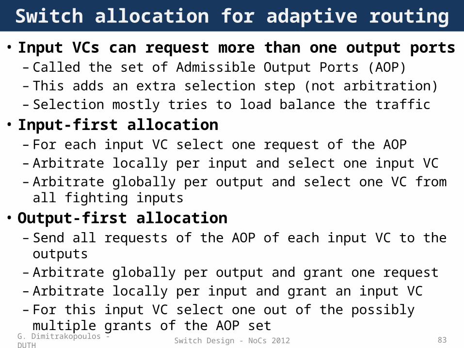
Switch allocation for adaptive routing• Input VCs can request more than one output ports
– Called the set of Admissible Output Ports (AOP)– This adds an extra selection step (not arbitration)– Selection mostly tries to load balance the traffic
• Input-first allocation– For each input VC select one request of the AOP– Arbitrate locally per input and select one input VC– Arbitrate globally per output and select one VC from all fighting
inputs• Output-first allocation
– Send all requests of the AOP of each input VC to the outputs– Arbitrate globally per output and grant one request– Arbitrate locally per input and grant an input VC– For this input VC select one out of the possibly multiple grants of
the AOP setG. Dimitrakopoulos - DUTH

Switch Design - NoCs 2012 84
VC allocation
• Virtual channels (VCs) allow multiple packet flows to share physical resources (buffers, channels)
• Before packets can proceed through router, need to claim ownership of VC buffer at next router– VC acquired by head flit, is inherited by body & tail flits
• VC allocator assigns waiting packets at inputs to output VC buffers that are not currently in use– N×V inputs (input VCs), N×V outputs (output VCs)– Once assigned, VC is used for entire packet’s duration in the switch
Input VCs
Output VCs
G. Dimitrakopoulos - DUTH

Switch Design - NoCs 2012 85
VC allocation example
• Input VC match to an output VC simultaneously with the rest– Even if it belongs to the same input– No port constraint as in switch allocators
• VC allocation refers to allocating buffer id (output VC) on the next router– Allocation can be both separable (2 arbitration steps) or centralized
Inputs VCs Output VCs
0
1In#0
In#1
In#2
Out#0
Requests Grants
2
3
4
5
0
1
2
3
4
5
Out#1
Out#2
Inputs VCs Output VCs
0
1In#0
In#1
In#2
Out#0
2
3
4
5
0
1
2
3
4
5
Out#1
Out#2
G. Dimitrakopoulos - DUTH
Switch Design - NoCs 2012 86
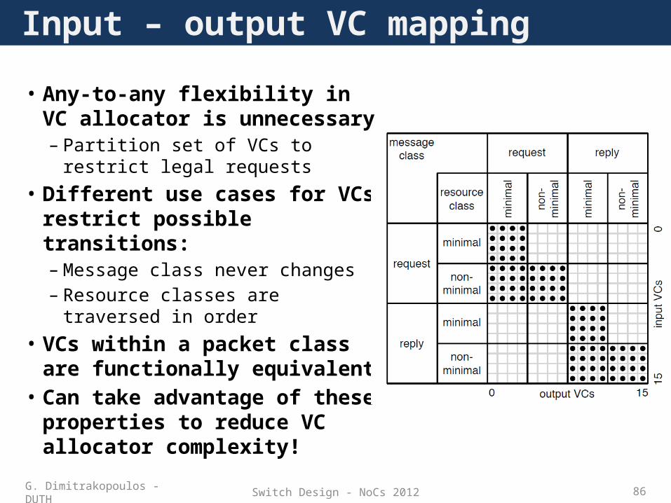
• Any-to-any flexibility in VC allocator is unnecessary– Partition set of VCs to restrict legal
requests• Different use cases for VCs restrict
possible transitions:– Message class never changes– Resource classes are traversed in
order• VCs within a packet class are
functionally equivalent• Can take advantage of these
properties to reduce VC allocator complexity!
Input – output VC mapping
G. Dimitrakopoulos - DUTH

Switch Design - NoCs 2012 87
VA single cycle or pipelined organization
• Header flits see longer latency than body/tail flits– RC, VA decisions taken for head flits and inherited to the rest of the
packet– Every flit fights for SA
• Can we parallelize SA and VA?G. Dimitrakopoulos - DUTH

Switch Design - NoCs 2012 88
The order of VC and switch allocation• VA first SA follows
– Only packets will an allocated output VC fight for SA
• VA and SA can be performed concurrently:– Speculate that waiting packets will successfully acquire a VC– Prioritize non-speculative requests over speculative ones– Speculation holds only for the head flits (The body/tail flits
always know their output VC)VA SA Description
Win Win Everything OK!! Leave the switch
Win Lose Allocated a VCRetry SA (not speculative - high priority next cycle)
Lose Win Does not know the output VCAllocated output port (grant lost – output idle)
Lose Lose Retry both VA and SA
G. Dimitrakopoulos - DUTH

Switch Design - NoCs 2012 89
Speculative switch allocation
• Perform switch allocation in parallel with VC allocation– Speculate that the latter will be successful– If so, saves delay, otherwise try again– Reduces zero-load latency, but adds complexity
• Prioritize non-speculative requests– Avoid performance degradation due to miss-speculation
• Usually implemented through secondary switch allocator– But need to prioritize non-speculative grants
G. Dimitrakopoulos - DUTH

Switch Design - NoCs 2012 90
Free list of VCs per output
• Can assign a VC non-speculatively after SA• A free list of output VCs exists at each output
– The flit that was granted access to this output receives the first free VC before leaving the switch
– If no VC available output port allocation slot is missed• Flit retries for switch allocation
• VCs are not unnecessarily occupied for flits that don’t win SA
G. Dimitrakopoulos - DUTH

Switch Design - NoCs 2012 91
VC buffer implementationStatic partitioning Dynamic partitioning
G. Dimitrakopoulos - DUTH
Linked-List Shared Buffer Implementation

Switch Design - NoCs 2012 92
VC-based switches with MARX units
• Merged Switch Allocation and Traversal can be applied to VC-based switches too
• VA can be run before or in parallel to SATG. Dimitrakopoulos - DUTH

Switch Design - NoCs 2012 93
VC-based switches with MARX units: Datapath
G. Dimitrakopoulos - DUTH

Switch Design - NoCs 2012 94
NoC: The science & art of on-chip connections
G. Dimitrakopoulos - DUTH
Network-on-Chip
MICROARCH
CIRCUITS
Micro-architecture of Network-on-Chip Routers Giorgos Dimitrakopoulos, Springer, mid 2013
ADVERTISEMENT

Switch Design - NoCs 2012 95
References (1) • W. J. Dally and B. Towles. Route packets, not wires: On-chip interconnection networks, DAC 2001• A. Kumar, et al. A 4.6tbits/s 3.6ghz single-cycle noc router with a novel switch allocator. In in 65nm CMOS”, ICCD-2007• A. Kumar, et al. “Express virtual channels: towards the ideal interconnection fabric”, ISCA ’07• H. Matsutani, et al. “Prediction router: A low-latency on-chip router architecture with multiple predictors”, IEEE Trans. Computers, 2011• G. Michelogiannakis, J. Balfour, and W. Dally, “Elastic bufferflow control for on-chip networks”, HPCA 2009.• Mitchell Hayenga, Mikko Lipasti, “The NoX Router”, MICRO 2011• T. Moscibroda and O. Mutlu. A case for bufferless routing in on-chip networks, ISCA 2009• R. Mullins, A. West, and S. Moore. Low-latency virtual-channel routers for on-chip networks. ISCA 2004• L.-S. Peh and W. J. Dally. A delay model and speculative architecture for pipelined router HPCA 2001• D. Wentzlaff, et al. “On-chip interconnection architecture of the tile processor. Micro, IEEE,2007• Y. J. Yoon, et al. “Virtual channels vs. Multiple Physical Networks”, DAC 2010• M. Azimi, et al. “Flexible and adaptive on-chip interconnect for terascale architectures,” Intel Technology Journal, 2009.• A. Golander, et al. “A cost-efficient L1–L2 multicore interconnect: Performance, power, and area considerations,” IEEE TCAS-I 2011.• P. Kumar, “Exploring concentration and channel slicing in on-chip network router,” HPCA 2009• M. Galles, “Spider: A high-speed network interconnect,” IEEE Micro, 1997.• A. S. Vaidya, et al. , “Lapses: A recipe for high performance adaptive router design”, HPCA 1999.• C. Batten Interconnection Networks Course, Columbia University• M. Katevenis, Packet Switch Architectures Course, University of Crete, Greece.• W. J. Dally, “Virtual-Channel Flow Control,” ISCA 1990.• D. U. Becker and W. J. Dally, “Allocator implementations for network-on-chip routers,”, SC 2009.• S. S. Mukherjee, et al., “A comparative study of arbitration algorithms for the Alpha 21364 pipelined router,” ASPLOS 2002.• Y. Tamir and H.-C. Chi, “Symmetric crossbar arbiters for VLSI communication switches,” IEEE Trans. on Par. and Distributed Systems, 1993.• J. Hurt, et al. , “Design and implementation of high-speed symmetric crossbar schedulers,” in ICC 1999• G. Ascia, et al., “Implementation and analysis of a new selection strategy for adaptive routing in networks-on-chip,” IEEE T. on Comp. 2008• P. Salihundam, et al. , “A 2Tb/s 6x4 Mesh Network with DVFS and 2.3Tb/s/W router in 45nm CMOS,” in Symp. VLSI Circuits, 2010.• P. Gupta and N. McKeown, “Design and implementation of a fast crossbar scheduler,” IEEE Micro 1999.• J. Flich and D. Bertozzi (editors), “Network on Chip in the Nanoscale Era”, CRC Press, 2010
G. Dimitrakopoulos - DUTH

Switch Design - NoCs 2012 96
References (2)• L. Pirvu et al. “The impact of link arbitration on switch performance,” HPCA, 1999.• M. Coppola, et al. “Spidergon: A Novel On-Chip Communication Network” IEEE SOC 2004. • W. Dally and C. Seitz. “Deadlock-Free Message Routing in Multiprocessor Interconnection Networks” IEEE Tran.on Computers, 1987• M. Karol, “Input vs Output Queuing on a Space-Division Packet Switch”, In IEEE Transactions on Communications, 1987.• Zhonghai Lu, et al. “Evaluation of on-chip networks using deflection routing”. In Proceedings of GLSVLSI, 2006.• Zhonghai Lu, et al.. “Layered switching for networks on chip”. DAC 2007• R. Ginosar, "Metastability and Synchronizers: A Tutorial," IEEE Design & Test, Sept/Oct. 2011.• G. Dimitrakopoulos, D. Bertozzi, “Switch architecture”, in J. Flich and D. Bertozzi (editors), “Network on Chip in the Nanoscale Era”, CRC
Press, 2010• G. Dimitrakopoulos, “Logic-level Design of Basic Switch Components”, in J. Flich and D. Bertozzi (editors), “Network on Chip in the
Nanoscale Era”, CRC Press, 2010• G. Dimitrakopoulos E. Kalligeros, “Dynamic-Priority Arbiter and Multiplexer Soft Macros for On-Chip Networks Switches”, DATE 2012• G. Dimitrakopoulos, E. Kalligeros, K. Galanopoulos, “Merged Switch allocation and traversal in Network-on-Chip Switches”, to appear in
IEEE transactions on Computers (available at IEEExplore preprints)• Se-Joong Lee et al. Packet-Switched On-Chip Interconnection Network for System-on-Chip Applications, IEEE TCAS II 2005.• Donghyun Kim et al. A Reconfigurable Crossbar Switch with Adaptive Bandwidth Control for Networks-on-Chip, ISCAS2005.• Anh Tran and Bevan Baas, "RoShaQ: High-Performance On-Chip Router with Shared Queues,“ iCCD 2011• Anh Tran et al. "A Reconfigurable Source-Synchronous On-Chip Network for GALS Many-Core Platforms,“ IEEE Trans.on CAD, 2010.• B. Dally and B. Towles, “Interconnection networks”, Morgan Kaufman 2004• C.A. Nicopoulos, “ViChaR: A Dynamic Virtual Channel Regulator for Network-on-Chip Routers “, MICRO 2006.• Clive Maxfield , “2D vs. 2.5D vs. 3D ICs 101” EE Times, Design 2012• Mike Santarini , “2.5D ICs are more than a stepping stone to 3D Ics”, EE Times, Design 2012• Nathan Binkert et al. , “The Role of Optics in Future High Radix Switch Design”, ISCA-2011• Eylon Caspi “Design Automation for Streaming Systems”, PhD Thesis, Berkeley 2005• C Minkenberg, M Gusat , “Design and performance of speculative flow control for high-radix datacenter interconnect switches”, JPDC
09• Peh, Li-Shiuan and Dally, William J., "Flit-Reservation Flow Control," in HPCA 1999• M. Gerla and L. Kleinrock. Flow Control: A Comparative Survey. IEEE Transactions on Communications, 1980.
G. Dimitrakopoulos - DUTH