Embed Size (px)
Citation preview
Switched-mode power supply 1
Switched-mode power supply
Interior view of an ATX SMPS: belowA: input EMI filtering; A: bridge rectifier;
B: input filter capacitors;Between B and C: primary side heat sink;
C: transformer;Between C and D: secondary side heat sink;
D: output filter coil;E: output filter capacitors.
The coil and large yellow capacitor below E are additional inputfiltering components that are mounted directly on the power input
connector and are not part of the main circuit board.
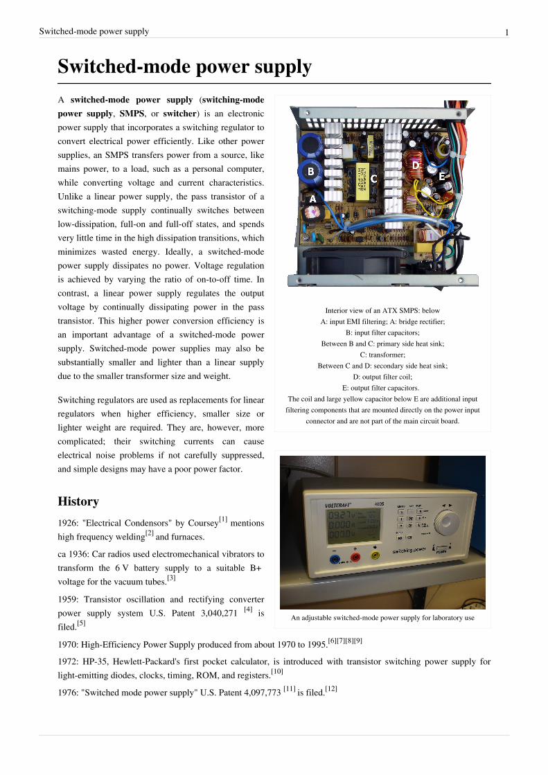
An adjustable switched-mode power supply for laboratory use
A switched-mode power supply (switching-modepower supply, SMPS, or switcher) is an electronicpower supply that incorporates a switching regulator toconvert electrical power efficiently. Like other powersupplies, an SMPS transfers power from a source, likemains power, to a load, such as a personal computer,while converting voltage and current characteristics.Unlike a linear power supply, the pass transistor of aswitching-mode supply continually switches betweenlow-dissipation, full-on and full-off states, and spendsvery little time in the high dissipation transitions, whichminimizes wasted energy. Ideally, a switched-modepower supply dissipates no power. Voltage regulationis achieved by varying the ratio of on-to-off time. Incontrast, a linear power supply regulates the outputvoltage by continually dissipating power in the passtransistor. This higher power conversion efficiency isan important advantage of a switched-mode powersupply. Switched-mode power supplies may also besubstantially smaller and lighter than a linear supplydue to the smaller transformer size and weight.
Switching regulators are used as replacements for linearregulators when higher efficiency, smaller size orlighter weight are required. They are, however, morecomplicated; their switching currents can causeelectrical noise problems if not carefully suppressed,and simple designs may have a poor power factor.
History
1926: "Electrical Condensors" by Coursey[1] mentionshigh frequency welding[2] and furnaces.
ca 1936: Car radios used electromechanical vibrators totransform the 6 V battery supply to a suitable B+voltage for the vacuum tubes.[3]
1959: Transistor oscillation and rectifying converterpower supply system U.S. Patent 3,040,271 [4] isfiled.[5]
1970: High-Efficiency Power Supply produced from about 1970 to 1995.[6][7][8][9]
1972: HP-35, Hewlett-Packard's first pocket calculator, is introduced with transistor switching power supply forlight-emitting diodes, clocks, timing, ROM, and registers.[10]
1976: "Switched mode power supply" U.S. Patent 4,097,773 [11] is filed.[12]
Switched-mode power supply 2
1977: Apple II is designed with a switching mode power supply. "For its time (1977) it was a breakthrough, sinceuntil then switching mode power supplies weren’t used. Designed by Rod Holt,".[13] "Rod Holt was brought in asproduct engineer and there were several flaws in Apple II that were never publicized. One thing Holt has to hiscredit is that he created the switching power supply that allowed us to do a very lightweight computer".[14]
1980: The HP8662A 10 kHz – 1.28 GHz synthesized signal generator went with a switched power supply.[15]
ExplanationA linear regulator provides the desired output voltage by dissipating excess power in ohmic losses (e.g., in a resistoror in the collector–emitter region of a pass transistor in its active mode). A linear regulator regulates either outputvoltage or current by dissipating the excess electric power in the form of heat, and hence its maximum powerefficiency is voltage-out/voltage-in since the volt difference is wasted.In contrast, a switched-mode power supply regulates either output voltage or current by switching ideal storageelements, like inductors and capacitors, into and out of different electrical configurations. Ideal switching elements(e.g., transistors operated outside of their active mode) have no resistance when "closed" and carry no current when"open", and so the converters can theoretically operate with 100% efficiency (i.e., all input power is delivered to theload; no power is wasted as dissipated heat).
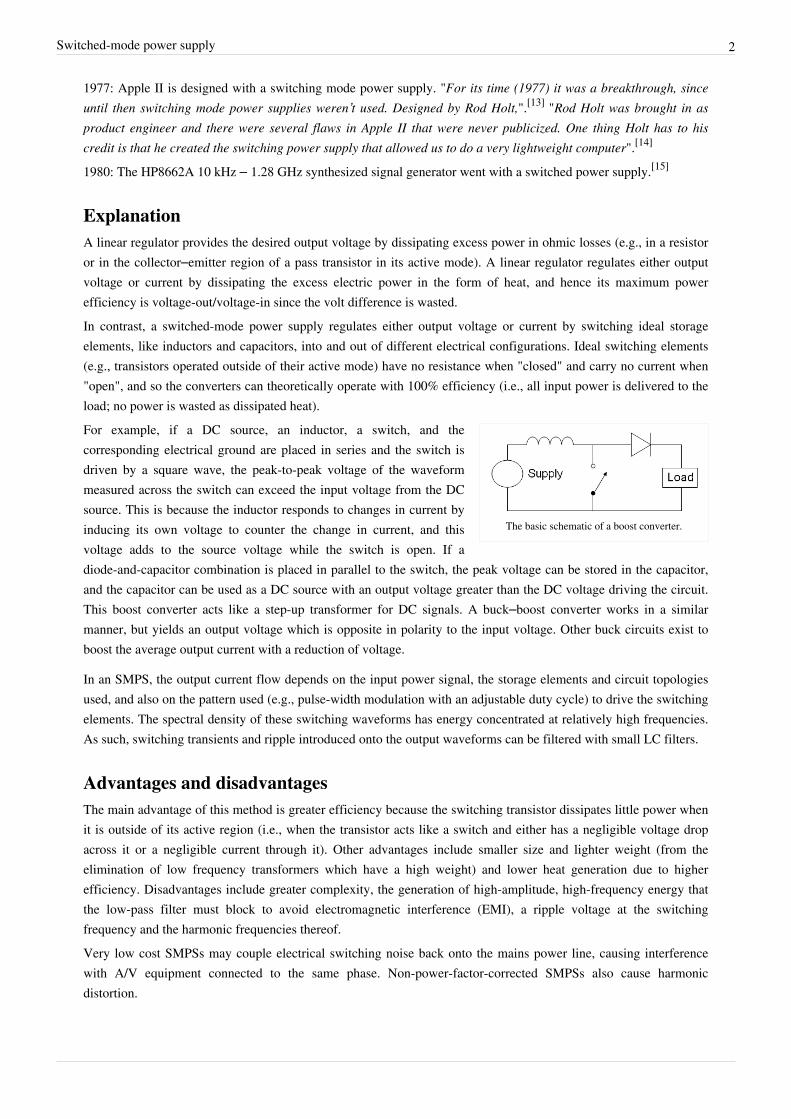
The basic schematic of a boost converter.
For example, if a DC source, an inductor, a switch, and thecorresponding electrical ground are placed in series and the switch isdriven by a square wave, the peak-to-peak voltage of the waveformmeasured across the switch can exceed the input voltage from the DCsource. This is because the inductor responds to changes in current byinducing its own voltage to counter the change in current, and thisvoltage adds to the source voltage while the switch is open. If adiode-and-capacitor combination is placed in parallel to the switch, the peak voltage can be stored in the capacitor,and the capacitor can be used as a DC source with an output voltage greater than the DC voltage driving the circuit.This boost converter acts like a step-up transformer for DC signals. A buck–boost converter works in a similarmanner, but yields an output voltage which is opposite in polarity to the input voltage. Other buck circuits exist toboost the average output current with a reduction of voltage.
In an SMPS, the output current flow depends on the input power signal, the storage elements and circuit topologiesused, and also on the pattern used (e.g., pulse-width modulation with an adjustable duty cycle) to drive the switchingelements. The spectral density of these switching waveforms has energy concentrated at relatively high frequencies.As such, switching transients and ripple introduced onto the output waveforms can be filtered with small LC filters.
Advantages and disadvantagesThe main advantage of this method is greater efficiency because the switching transistor dissipates little power whenit is outside of its active region (i.e., when the transistor acts like a switch and either has a negligible voltage dropacross it or a negligible current through it). Other advantages include smaller size and lighter weight (from theelimination of low frequency transformers which have a high weight) and lower heat generation due to higherefficiency. Disadvantages include greater complexity, the generation of high-amplitude, high-frequency energy thatthe low-pass filter must block to avoid electromagnetic interference (EMI), a ripple voltage at the switchingfrequency and the harmonic frequencies thereof.Very low cost SMPSs may couple electrical switching noise back onto the mains power line, causing interferencewith A/V equipment connected to the same phase. Non-power-factor-corrected SMPSs also cause harmonicdistortion.
Switched-mode power supply 3
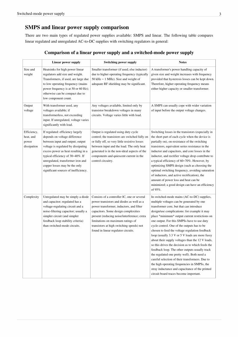
SMPS and linear power supply comparisonThere are two main types of regulated power supplies available: SMPS and linear. The following table compareslinear regulated and unregulated AC-to-DC supplies with switching regulators in general:
Comparison of a linear power supply and a switched-mode power supply
Linear power supply Switching power supply Notes
Size andweight
Heatsinks for high power linearregulators add size and weight.Transformers, if used, are large dueto low operating frequency (mainspower frequency is at 50 or 60 Hz);otherwise can be compact due tolow component count.
Smaller transformer (if used; else inductor)due to higher operating frequency (typically50 kHz – 1 MHz). Size and weight ofadequate RF shielding may be significant.
A transformer's power handling capacity ofgiven size and weight increases with frequencyprovided that hysteresis losses can be kept down.Therefore, higher operating frequency meanseither higher capacity or smaller transformer.
Outputvoltage
With transformer used, anyvoltages available; iftransformerless, not exceedinginput. If unregulated, voltage variessignificantly with load.
Any voltages available, limited only bytransistor breakdown voltages in manycircuits. Voltage varies little with load.
A SMPS can usually cope with wider variationof input before the output voltage changes.
Efficiency,heat, andpowerdissipation
If regulated: efficiency largelydepends on voltage differencebetween input and output; outputvoltage is regulated by dissipatingexcess power as heat resulting in atypical efficiency of 30–40%. Ifunregulated, transformer iron andcopper losses may be the onlysignificant sources of inefficiency.
Output is regulated using duty cyclecontrol; the transistors are switched fully onor fully off, so very little resistive lossesbetween input and the load. The only heatgenerated is in the non-ideal aspects of thecomponents and quiescent current in thecontrol circuitry.
Switching losses in the transistors (especially inthe short part of each cycle when the device ispartially on), on-resistance of the switchingtransistors, equivalent series resistance in theinductor and capacitors, and core losses in theinductor, and rectifier voltage drop contribute toa typical efficiency of 60–70%. However, byoptimizing SMPS design (such as choosing theoptimal switching frequency, avoiding saturationof inductors, and active rectification), theamount of power loss and heat can beminimized; a good design can have an efficiencyof 95%.
Complexity Unregulated may be simply a diodeand capacitor; regulated has avoltage-regulating circuit and anoise-filtering capacitor; usually asimpler circuit (and simplerfeedback loop stability criteria)than switched-mode circuits.
Consists of a controller IC, one or severalpower transistors and diodes as well as apower transformer, inductors, and filtercapacitors. Some design complexitiespresent (reducing noise/interference; extralimitations on maximum ratings oftransistors at high switching speeds) notfound in linear regulator circuits.
In switched-mode mains (AC-to-DC) supplies,multiple voltages can be generated by onetransformer core, but that can introducedesign/use complications: for example it mayplace *minimum* output current restrictions onone output. For this SMPSs have to use dutycycle control. One of the outputs has to bechosen to feed the voltage regulation feedbackloop (usually 3.3 V or 5 V loads are more fussyabout their supply voltages than the 12 V loads,so this drives the decision as to which feeds thefeedback loop. The other outputs usually trackthe regulated one pretty well). Both need acareful selection of their transformers. Due tothe high operating frequencies in SMPSs, thestray inductance and capacitance of the printedcircuit board traces become important.
Switched-mode power supply 4
Radiofrequencyinterference
Mild high-frequency interferencemay be generated by AC rectifierdiodes under heavy current loading,while most other supply typesproduce no high-frequencyinterference. Some mains huminduction into unshielded cables,problematical for low-signal audio.
EMI/RFI produced due to the current beingswitched on and off sharply. Therefore,EMI filters and RF shielding are needed toreduce the disruptive interference.
Long wires between the components may reducethe high frequency filter efficiency provided bythe capacitors at the inlet and outlet. Stableswitching frequency may be important.
Electronicnoise at theoutputterminals
Unregulated PSUs may have a littleAC ripple superimposed upon theDC component at twice mainsfrequency (100–120 Hz). It cancause audible mains hum in audioequipment, brightness ripples orbanded distortions in analogsecurity cameras.
Noisier due to the switching frequency ofthe SMPS. An unfiltered output may causeglitches in digital circuits or noise in audiocircuits.
This can be suppressed with capacitors and otherfiltering circuitry in the output stage. With aswitched mode PSU the switching frequency canbe chosen to keep the noise out of the circuitsworking frequency band (e.g., for audio systemsabove the range of human hearing)
Electronicnoise at theinputterminals
Causes harmonic distortion to theinput AC, but relatively little or nohigh frequency noise.
Very low cost SMPS may couple electricalswitching noise back onto the mains powerline, causing interference with A/Vequipment connected to the same phase.Non power-factor-corrected SMPSs alsocause harmonic distortion.
This can be prevented if a (properly earthed)EMI/RFI filter is connected between the inputterminals and the bridge rectifier.
Acousticnoise
Faint, usually inaudible mains hum,usually due to vibration ofwindings in the transformer ormagnetostriction.
Usually inaudible to most humans, unlessthey have a fan or areunloaded/malfunctioning, or use a switchingfrequency within the audio range, or thelaminations of the coil vibrate at asubharmonic of the operating frequency.
The operating frequency of an unloaded SMPSis sometimes in the audible human range, andmay sound subjectively quite loud for peoplewho have hyperacusis in the relevant frequencyrange.
Power factor Low for a regulated supply becausecurrent is drawn from the mains atthe peaks of the voltage sinusoid,unless a choke-input orresistor-input circuit follows therectifier (now rare).
Ranging from very low to medium since asimple SMPS without PFC draws currentspikes at the peaks of the AC sinusoid.
Active/passive power factor correction in theSMPS can offset this problem and are evenrequired by some electric regulation authorities,particularly in the EU. The internal resistance oflow-power transformers in linear power suppliesusually limits the peak current each cycle andthus gives a better power factor than manyswitched-mode power supplies that directlyrectify the mains with little series resistance.
Inrushcurrent
Large current when mains-poweredlinear power supply equipment isswitched on until magnetic flux oftransformer stabilises andcapacitors charge completely,unless a slow-start circuit is used.
Extremely large peak "in-rush" surgecurrent limited only by the impedance of theinput supply and any series resistance to thefilter capacitors.
Empty filter capacitors initially draw largeamounts of current as they charge up, with largercapacitors drawing larger amounts of peakcurrent. Being many times above the normaloperating current, this greatly stressescomponents subject to the surge, complicatesfuse selection to avoid nuisance blowing andmay cause problems with equipment employingovercurrent protection such as uninterruptiblepower supplies. Mitigated by use of a suitablesoft-start circuit or series resistor.
Switched-mode power supply 5
Risk ofelectricshock
Supplies with transformers isolatethe incoming power supply fromthe powered device and so allowmetalwork of the enclosure to begrounded safely. Dangerous ifprimary/secondary insulationbreaks down, unlikely withreasonable design. Transformerlessmains-operated supply dangerous.In both linear and switch-mode themains, and possibly the outputvoltages, are hazardous and mustbe well-isolated.
Common rail of equipment (includingcasing) is energized to half the mainsvoltage, but at high impedance, unlessequipment is earthed/grounded or doesn'tcontain EMI/RFI filtering at the inputterminals.
Due to regulations concerning EMI/RFIradiation, many SMPS contain EMI/RFI filteringat the input stage before the bridge rectifierconsisting of capacitors and inductors. Twocapacitors are connected in series with the Liveand Neutral rails with the Earth connection inbetween the two capacitors. This forms acapacitive divider that energizes the commonrail at half mains voltage. Its high impedancecurrent source can provide a tingling or a 'bite' tothe operator or can be exploited to light an EarthFault LED. However, this current may causenuisance tripping on the most sensitiveresidual-current devices.
Risk ofequipmentdamage
Very low, unless a short occursbetween the primary and secondarywindings or the regulator fails byshorting internally.
Can fail so as to make output voltage veryhigh. Stress on capacitors may cause themto explode. Can in some cases destroy inputstages in amplifiers if floating voltageexceeds transistor base-emitter breakdownvoltage, causing the transistor's gain to dropand noise levels to increase.[16] Mitigatedby good failsafe design. Failure of acomponent in the SMPS itself can causefurther damage to other PSU components;can be difficult to troubleshoot.
The floating voltage is caused by capacitorsbridging the primary and secondary sides of thepower supply. A connection to an earthedequipment will cause a momentary (andpotentially destructive) spike in current at theconnector as the voltage at the secondary side ofthe capacitor equalizes to earth potential.
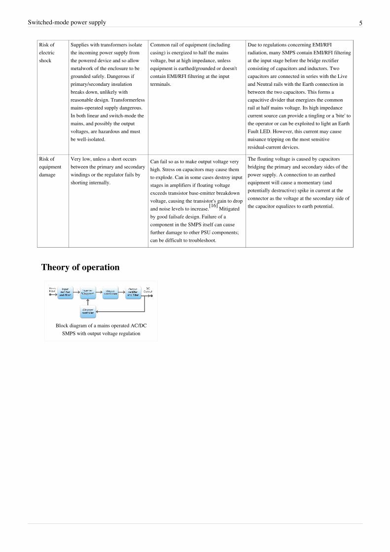
Theory of operation
Block diagram of a mains operated AC/DCSMPS with output voltage regulation
Switched-mode power supply 6
Input rectifier stage
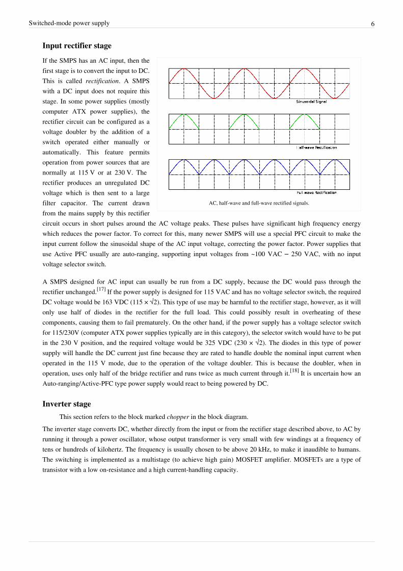
AC, half-wave and full-wave rectified signals.
If the SMPS has an AC input, then thefirst stage is to convert the input to DC.This is called rectification. A SMPSwith a DC input does not require thisstage. In some power supplies (mostlycomputer ATX power supplies), therectifier circuit can be configured as avoltage doubler by the addition of aswitch operated either manually orautomatically. This feature permitsoperation from power sources that arenormally at 115 V or at 230 V. Therectifier produces an unregulated DCvoltage which is then sent to a largefilter capacitor. The current drawnfrom the mains supply by this rectifiercircuit occurs in short pulses around the AC voltage peaks. These pulses have significant high frequency energywhich reduces the power factor. To correct for this, many newer SMPS will use a special PFC circuit to make theinput current follow the sinusoidal shape of the AC input voltage, correcting the power factor. Power supplies thatuse Active PFC usually are auto-ranging, supporting input voltages from ~100 VAC – 250 VAC, with no inputvoltage selector switch.
A SMPS designed for AC input can usually be run from a DC supply, because the DC would pass through therectifier unchanged.[17] If the power supply is designed for 115 VAC and has no voltage selector switch, the requiredDC voltage would be 163 VDC (115 × √2). This type of use may be harmful to the rectifier stage, however, as it willonly use half of diodes in the rectifier for the full load. This could possibly result in overheating of thesecomponents, causing them to fail prematurely. On the other hand, if the power supply has a voltage selector switchfor 115/230V (computer ATX power supplies typically are in this category), the selector switch would have to be putin the 230 V position, and the required voltage would be 325 VDC (230 × √2). The diodes in this type of powersupply will handle the DC current just fine because they are rated to handle double the nominal input current whenoperated in the 115 V mode, due to the operation of the voltage doubler. This is because the doubler, when inoperation, uses only half of the bridge rectifier and runs twice as much current through it.[18] It is uncertain how anAuto-ranging/Active-PFC type power supply would react to being powered by DC.
Inverter stageThis section refers to the block marked chopper in the block diagram.
The inverter stage converts DC, whether directly from the input or from the rectifier stage described above, to AC byrunning it through a power oscillator, whose output transformer is very small with few windings at a frequency oftens or hundreds of kilohertz. The frequency is usually chosen to be above 20 kHz, to make it inaudible to humans.The switching is implemented as a multistage (to achieve high gain) MOSFET amplifier. MOSFETs are a type oftransistor with a low on-resistance and a high current-handling capacity.
Switched-mode power supply 7
Voltage converter and output rectifierIf the output is required to be isolated from the input, as is usually the case in mains power supplies, the inverted ACis used to drive the primary winding of a high-frequency transformer. This converts the voltage up or down to therequired output level on its secondary winding. The output transformer in the block diagram serves this purpose.If a DC output is required, the AC output from the transformer is rectified. For output voltages above ten volts or so,ordinary silicon diodes are commonly used. For lower voltages, Schottky diodes are commonly used as the rectifierelements; they have the advantages of faster recovery times than silicon diodes (allowing low-loss operation athigher frequencies) and a lower voltage drop when conducting. For even lower output voltages, MOSFETs may beused as synchronous rectifiers; compared to Schottky diodes, these have even lower conducting state voltage drops.The rectified output is then smoothed by a filter consisting of inductors and capacitors. For higher switchingfrequencies, components with lower capacitance and inductance are needed.Simpler, non-isolated power supplies contain an inductor instead of a transformer. This type includes boostconverters, buck converters, and the buck-boost converters. These belong to the simplest class of single input, singleoutput converters which use one inductor and one active switch. The buck converter reduces the input voltage indirect proportion to the ratio of conductive time to the total switching period, called the duty cycle. For example anideal buck converter with a 10 V input operating at a 50% duty cycle will produce an average output voltage of 5 V.A feedback control loop is employed to regulate the output voltage by varying the duty cycle to compensate forvariations in input voltage. The output voltage of a boost converter is always greater than the input voltage and thebuck-boost output voltage is inverted but can be greater than, equal to, or less than the magnitude of its input voltage.There are many variations and extensions to this class of converters but these three form the basis of almost allisolated and non-isolated DC to DC converters. By adding a second inductor the Ćuk and SEPIC converters can beimplemented, or, by adding additional active switches, various bridge converters can be realized.Other types of SMPSs use a capacitor-diode voltage multiplier instead of inductors and transformers. These aremostly used for generating high voltages at low currents (Cockcroft-Walton generator). The low voltage variant iscalled charge pump.
Regulation
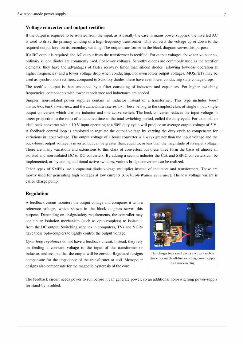
This charger for a small device such as a mobilephone is a simple off-line switching power supply
in a European plug.
A feedback circuit monitors the output voltage and compares it with areference voltage, which shown in the block diagram serves thispurpose. Depending on design/safety requirements, the controller maycontain an isolation mechanism (such as opto-couplers) to isolate itfrom the DC output. Switching supplies in computers, TVs and VCRshave these opto-couplers to tightly control the output voltage.
Open-loop regulators do not have a feedback circuit. Instead, they relyon feeding a constant voltage to the input of the transformer orinductor, and assume that the output will be correct. Regulated designscompensate for the impedance of the transformer or coil. Monopolardesigns also compensate for the magnetic hysteresis of the core.
The feedback circuit needs power to run before it can generate power, so an additional non-switching power-supplyfor stand-by is added.
Switched-mode power supply 8
Transformer designAny switched-mode power supply that gets its power from an AC power line (called an "off-line" converters)requires a transformer for galvanic isolation. Some DC-to-DC converters may also include a transformer, althoughisolation may not be critical in these cases. SMPS transformers run at high frequency. Most of the cost savings (andspace savings) in off-line power supplies result from the smaller size of high frequency transformer compared to the50/60 Hz transformers formerly used. There are additional design tradeoffs.The terminal voltage of a transformer is proportional to the product of the core area, magnetic flux, and frequency.By using a much higher frequency, the core area (and so the mass of the core) can be greatly reduced. However, corelosses increase at higher frequencies. Cores generally use ferrite material which has a low loss at the highfrequencies and high flux densities used. The laminated iron cores of lower-frequency (<400 Hz) transformers wouldbe unacceptably lossy at switching frequencies of a few kilohertz. Also, more energy is lost during transitions of theswitching semiconductor at higher frequencies. Furthermore, more attention to the physical layout of the circuitboard is required as parasitics become more significant, and the amount of electromagnetic interference will be morepronounced.
Copper lossAt low frequencies (such as the line frequency of 50 or 60 Hz), designers can usually ignore the skin effect. For thesefrequencies, the skin effect is only significant when the conductors are large, more than 0.3 inches (7.6 mm) indiameter.Switching power supplies must pay more attention to the skin effect because it is a source of power loss. At 500 kHz,the skin depth in copper is about 0.003 inches (0.076 mm) – a dimension smaller than the typical wires used in apower supply. The effective resistance of conductors increases, because current concentrates near the surface of theconductor and the inner portion carries less current than at low frequencies.The skin effect is exacerbated by the harmonics present in the high speed PWM switching waveforms. Theappropriate skin depth is not just the depth at the fundamental, but also the skin depths at the harmonics.In addition to the skin effect, there is also a proximity effect, which is another source of power loss.
Power factorSimple off-line switched mode power supplies incorporate a simple full-wave rectifier connected to a large energystoring capacitor. Such SMPSs draw current from the AC line in short pulses when the mains instantaneous voltageexceeds the voltage across this capacitor. During the remaining portion of the AC cycle the capacitor providesenergy to the power supply.As a result, the input current of such basic switched mode power supplies has high harmonic content and relativelylow power factor. This creates extra load on utility lines, increases heating of building wiring, the utilitytransformers, and standard AC electric motors, and may cause stability problems in some applications such as inemergency generator systems or aircraft generators. Harmonics can be removed by filtering, but the filters areexpensive. Unlike displacement power factor created by linear inductive or capacitive loads, this distortion cannot becorrected by addition of a single linear component. Additional circuits are required to counteract the effect of thebrief current pulses. Putting a current regulated boost chopper stage after the off-line rectifier (to charge the storagecapacitor) can correct the power factor, but increases the complexity and cost.In 2001, the European Union put into effect the standard IEC/EN61000-3-2 to set limits on the harmonics of the ACinput current up to the 40th harmonic for equipment above 75 W. The standard defines four classes of equipmentdepending on its type and current waveform. The most rigorous limits (class D) are established for personalcomputers, computer monitors, and TV receivers. To comply with these requirements, modern switched-mode powersupplies normally include an additional power factor correction (PFC) stage.
Switched-mode power supply 9
TypesSwitched-mode power supplies can be classified according to the circuit topology. The most important distinction isbetween isolated converters and non-isolated ones.
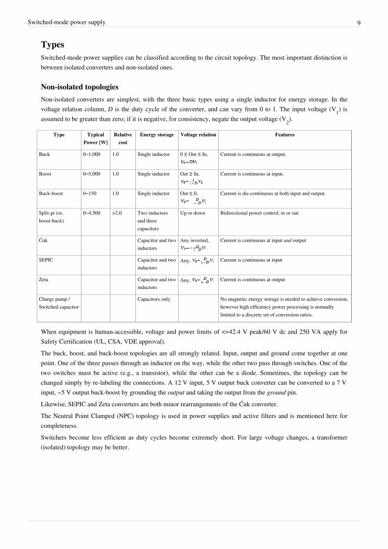
Non-isolated topologiesNon-isolated converters are simplest, with the three basic types using a single inductor for energy storage. In thevoltage relation column, D is the duty cycle of the converter, and can vary from 0 to 1. The input voltage (V1) isassumed to be greater than zero; if it is negative, for consistency, negate the output voltage (V2).
Type TypicalPower [W]
Relativecost
Energy storage Voltage relation Features
Buck 0–1,000 1.0 Single inductor 0 ≤ Out ≤ In, Current is continuous at output.
Boost 0–5,000 1.0 Single inductor Out ≥ In, Current is continuous at input.
Buck-boost 0–150 1.0 Single inductor Out ≤ 0, Current is dis-continuous at both input and output.
Split-pi (or,boost-buck)
0–4,500 >2.0 Two inductorsand threecapacitors
Up or down Bidirectional power control; in or out
Ćuk Capacitor and twoinductors
Any inverted, Current is continuous at input and output
SEPIC Capacitor and twoinductors
Any, Current is continuous at input
Zeta Capacitor and twoinductors
Any, Current is continuous at output
Charge pump /Switched capacitor
Capacitors only No magnetic energy storage is needed to achieve conversion,however high efficiency power processing is normallylimited to a discrete set of conversion ratios.
When equipment is human-accessible, voltage and power limits of <=42.4 V peak/60 V dc and 250 VA apply forSafety Certification (UL, CSA, VDE approval).The buck, boost, and buck-boost topologies are all strongly related. Input, output and ground come together at onepoint. One of the three passes through an inductor on the way, while the other two pass through switches. One of thetwo switches must be active (e.g., a transistor), while the other can be a diode. Sometimes, the topology can bechanged simply by re-labeling the connections. A 12 V input, 5 V output buck converter can be converted to a 7 Vinput, −5 V output buck-boost by grounding the output and taking the output from the ground pin.Likewise, SEPIC and Zeta converters are both minor rearrangements of the Ćuk converter.The Neutral Point Clamped (NPC) topology is used in power supplies and active filters and is mentioned here forcompleteness.Switchers become less efficient as duty cycles become extremely short. For large voltage changes, a transformer(isolated) topology may be better.
Switched-mode power supply 10
Isolated topologiesAll isolated topologies include a transformer, and thus can produce an output of higher or lower voltage than theinput by adjusting the turns ratio.[19][20] For some topologies, multiple windings can be placed on the transformer toproduce multiple output voltages.[21] Some converters use the transformer for energy storage, while others use aseparate inductor.
Type Power[W]
Relativecost
Inputrange
[V]
Energy storage Features
Flyback 0–250 1.0 5–600 Mutual Inductors Isolated form of the buck-boost converter.1
Ringing choke converter(RCC)
0–150 1.0 5–600 Transformer Low-cost self-oscillating flyback variant.
Half-forward 0–250 1.2 5–500 Inductor
Forward2 100-200 60–200 Inductor Isolated form of buck-boost converter
Resonant forward 0–60 1.0 60–400 Inductor and capacitor Single rail input, unregulated output, highefficiency, low EMI.[22]
Push-pull 100–1,000 1.75 50–1,000 Inductor
Half-bridge 0–2,000 1.9 50–1,000 Inductor
Full-bridge 400–5,000 >2.0 50–1,000 Inductor Very efficient use of transformer, used for highestpowers.
Resonant, zero voltageswitched
>1,000 >2.0 Inductor and capacitor
Isolated Ćuk Two capacitors and twoinductors
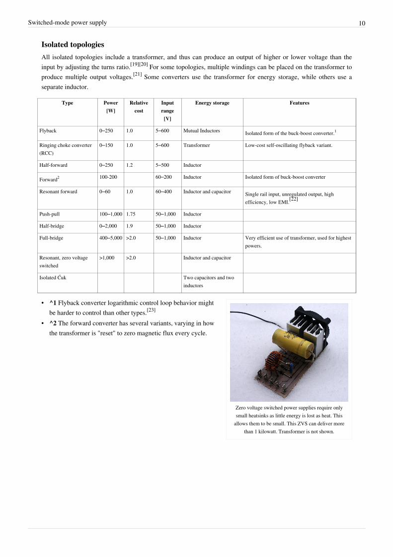
Zero voltage switched power supplies require onlysmall heatsinks as little energy is lost as heat. This
allows them to be small. This ZVS can deliver morethan 1 kilowatt. Transformer is not shown.
• ^1 Flyback converter logarithmic control loop behavior mightbe harder to control than other types.[23]
• ^2 The forward converter has several variants, varying in howthe transformer is "reset" to zero magnetic flux every cycle.
Switched-mode power supply 11
Quasi-resonant zero-current/zero-voltage switch
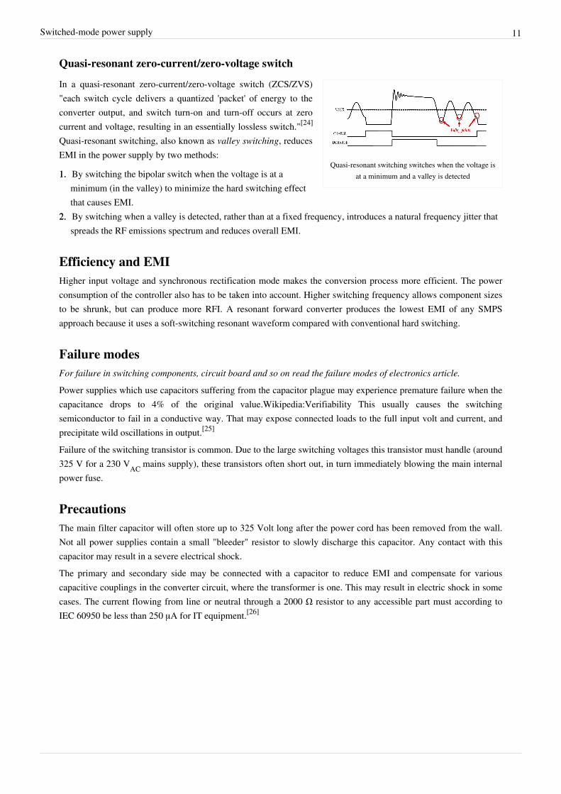
Quasi-resonant switching switches when the voltage isat a minimum and a valley is detected
In a quasi-resonant zero-current/zero-voltage switch (ZCS/ZVS)"each switch cycle delivers a quantized 'packet' of energy to theconverter output, and switch turn-on and turn-off occurs at zerocurrent and voltage, resulting in an essentially lossless switch."[24]
Quasi-resonant switching, also known as valley switching, reducesEMI in the power supply by two methods:
1.1. By switching the bipolar switch when the voltage is at aminimum (in the valley) to minimize the hard switching effectthat causes EMI.
2.2. By switching when a valley is detected, rather than at a fixed frequency, introduces a natural frequency jitter thatspreads the RF emissions spectrum and reduces overall EMI.
Efficiency and EMIHigher input voltage and synchronous rectification mode makes the conversion process more efficient. The powerconsumption of the controller also has to be taken into account. Higher switching frequency allows component sizesto be shrunk, but can produce more RFI. A resonant forward converter produces the lowest EMI of any SMPSapproach because it uses a soft-switching resonant waveform compared with conventional hard switching.
Failure modesFor failure in switching components, circuit board and so on read the failure modes of electronics article.
Power supplies which use capacitors suffering from the capacitor plague may experience premature failure when thecapacitance drops to 4% of the original value.Wikipedia:Verifiability This usually causes the switchingsemiconductor to fail in a conductive way. That may expose connected loads to the full input volt and current, andprecipitate wild oscillations in output.[25]
Failure of the switching transistor is common. Due to the large switching voltages this transistor must handle (around325 V for a 230 VAC mains supply), these transistors often short out, in turn immediately blowing the main internalpower fuse.
PrecautionsThe main filter capacitor will often store up to 325 Volt long after the power cord has been removed from the wall.Not all power supplies contain a small "bleeder" resistor to slowly discharge this capacitor. Any contact with thiscapacitor may result in a severe electrical shock.The primary and secondary side may be connected with a capacitor to reduce EMI and compensate for variouscapacitive couplings in the converter circuit, where the transformer is one. This may result in electric shock in somecases. The current flowing from line or neutral through a 2000 Ω resistor to any accessible part must according toIEC 60950 be less than 250 μA for IT equipment.[26]
Switched-mode power supply 12
Applications
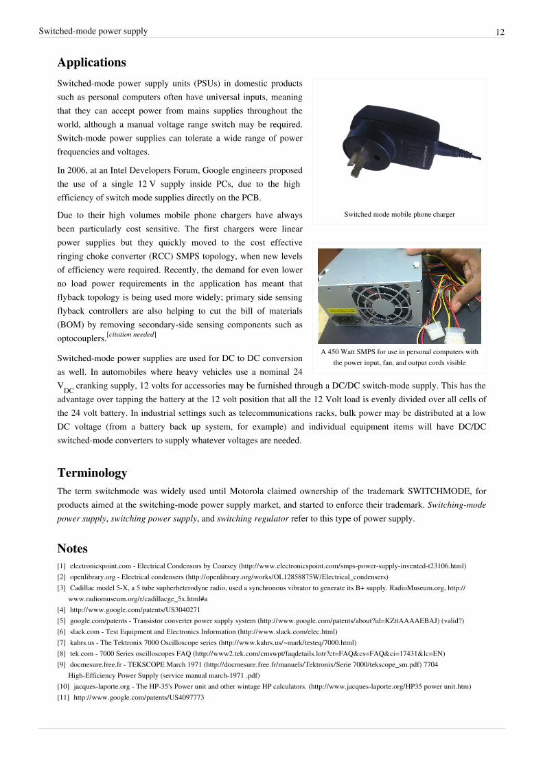
Switched mode mobile phone charger
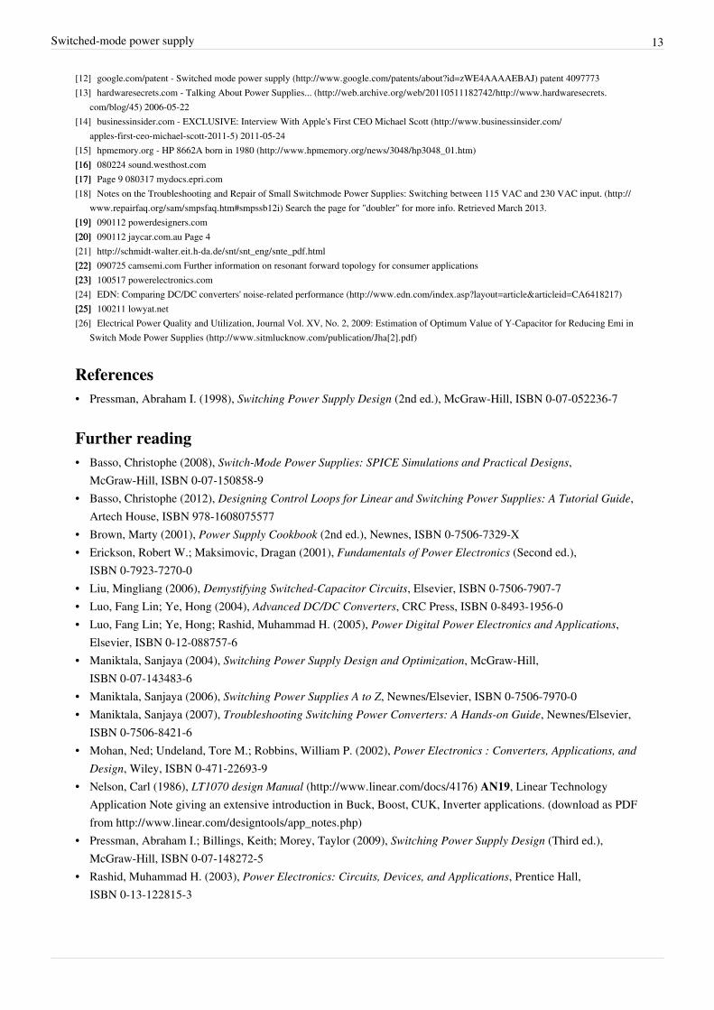
A 450 Watt SMPS for use in personal computers withthe power input, fan, and output cords visible
Switched-mode power supply units (PSUs) in domestic productssuch as personal computers often have universal inputs, meaningthat they can accept power from mains supplies throughout theworld, although a manual voltage range switch may be required.Switch-mode power supplies can tolerate a wide range of powerfrequencies and voltages.
In 2006, at an Intel Developers Forum, Google engineers proposedthe use of a single 12 V supply inside PCs, due to the highefficiency of switch mode supplies directly on the PCB.
Due to their high volumes mobile phone chargers have alwaysbeen particularly cost sensitive. The first chargers were linearpower supplies but they quickly moved to the cost effectiveringing choke converter (RCC) SMPS topology, when new levelsof efficiency were required. Recently, the demand for even lowerno load power requirements in the application has meant thatflyback topology is being used more widely; primary side sensingflyback controllers are also helping to cut the bill of materials(BOM) by removing secondary-side sensing components such asoptocouplers.[citation needed]
Switched-mode power supplies are used for DC to DC conversionas well. In automobiles where heavy vehicles use a nominal 24VDC cranking supply, 12 volts for accessories may be furnished through a DC/DC switch-mode supply. This has theadvantage over tapping the battery at the 12 volt position that all the 12 Volt load is evenly divided over all cells ofthe 24 volt battery. In industrial settings such as telecommunications racks, bulk power may be distributed at a lowDC voltage (from a battery back up system, for example) and individual equipment items will have DC/DCswitched-mode converters to supply whatever voltages are needed.
TerminologyThe term switchmode was widely used until Motorola claimed ownership of the trademark SWITCHMODE, forproducts aimed at the switching-mode power supply market, and started to enforce their trademark. Switching-modepower supply, switching power supply, and switching regulator refer to this type of power supply.
Notes[1] electronicspoint.com - Electrical Condensors by Coursey (http:/ / www. electronicspoint. com/ smps-power-supply-invented-t23106. html)[2] openlibrary.org - Electrical condensers (http:/ / openlibrary. org/ works/ OL12858875W/ Electrical_condensers)[3] Cadillac model 5-X, a 5 tube supherheterodyne radio, used a synchronous vibrator to generate its B+ supply. RadioMuseum.org, http:/ /
www. radiomuseum. org/ r/ cadillacge_5x. html#a[4] http:/ / www. google. com/ patents/ US3040271[5] google.com/patents - Transistor converter power supply system (http:/ / www. google. com/ patents/ about?id=KZttAAAAEBAJ) (valid?)[6] slack.com - Test Equipment and Electronics Information (http:/ / www. slack. com/ elec. html)[7] kahrs.us - The Tektronix 7000 Oscilloscope series (http:/ / www. kahrs. us/ ~mark/ testeq/ 7000. html)[8] tek.com - 7000 Series oscilloscopes FAQ (http:/ / www2. tek. com/ cmswpt/ faqdetails. lotr?ct=FAQ& cs=FAQ& ci=17431& lc=EN)[9] docmesure.free.fr - TEKSCOPE March 1971 (http:/ / docmesure. free. fr/ manuels/ Tektronix/ Serie 7000/ tekscope_sm. pdf) 7704
High-Efficiency Power Supply (service manual march-1971 .pdf)[10] jacques-laporte.org - The HP-35's Power unit and other wintage HP calculators. (http:/ / www. jacques-laporte. org/ HP35 power unit. htm)[11] http:/ / www. google. com/ patents/ US4097773
Switched-mode power supply 13
[12] google.com/patent - Switched mode power supply (http:/ / www. google. com/ patents/ about?id=zWE4AAAAEBAJ) patent 4097773[13] hardwaresecrets.com - Talking About Power Supplies... (http:/ / web. archive. org/ web/ 20110511182742/ http:/ / www. hardwaresecrets.
com/ blog/ 45) 2006-05-22[14] businessinsider.com - EXCLUSIVE: Interview With Apple's First CEO Michael Scott (http:/ / www. businessinsider. com/
apples-first-ceo-michael-scott-2011-5) 2011-05-24[15] hpmemory.org - HP 8662A born in 1980 (http:/ / www. hpmemory. org/ news/ 3048/ hp3048_01. htm)[16][16] 080224 sound.westhost.com[17][17] Page 9 080317 mydocs.epri.com[18] Notes on the Troubleshooting and Repair of Small Switchmode Power Supplies: Switching between 115 VAC and 230 VAC input. (http:/ /
www. repairfaq. org/ sam/ smpsfaq. htm#smpssb12i) Search the page for "doubler" for more info. Retrieved March 2013.[19][19] 090112 powerdesigners.com[20][20] 090112 jaycar.com.au Page 4[21] http:/ / schmidt-walter. eit. h-da. de/ snt/ snt_eng/ snte_pdf. html[22][22] 090725 camsemi.com Further information on resonant forward topology for consumer applications[23][23] 100517 powerelectronics.com[24] EDN: Comparing DC/DC converters' noise-related performance (http:/ / www. edn. com/ index. asp?layout=article& articleid=CA6418217)[25][25] 100211 lowyat.net[26] Electrical Power Quality and Utilization, Journal Vol. XV, No. 2, 2009: Estimation of Optimum Value of Y-Capacitor for Reducing Emi in
Switch Mode Power Supplies (http:/ / www. sitmlucknow. com/ publication/ Jha[2]. pdf)
References• Pressman, Abraham I. (1998), Switching Power Supply Design (2nd ed.), McGraw-Hill, ISBN 0-07-052236-7
Further reading• Basso, Christophe (2008), Switch-Mode Power Supplies: SPICE Simulations and Practical Designs,
McGraw-Hill, ISBN 0-07-150858-9• Basso, Christophe (2012), Designing Control Loops for Linear and Switching Power Supplies: A Tutorial Guide,
Artech House, ISBN 978-1608075577• Brown, Marty (2001), Power Supply Cookbook (2nd ed.), Newnes, ISBN 0-7506-7329-X• Erickson, Robert W.; Maksimovic, Dragan (2001), Fundamentals of Power Electronics (Second ed.),
ISBN 0-7923-7270-0• Liu, Mingliang (2006), Demystifying Switched-Capacitor Circuits, Elsevier, ISBN 0-7506-7907-7• Luo, Fang Lin; Ye, Hong (2004), Advanced DC/DC Converters, CRC Press, ISBN 0-8493-1956-0• Luo, Fang Lin; Ye, Hong; Rashid, Muhammad H. (2005), Power Digital Power Electronics and Applications,
Elsevier, ISBN 0-12-088757-6• Maniktala, Sanjaya (2004), Switching Power Supply Design and Optimization, McGraw-Hill,
ISBN 0-07-143483-6• Maniktala, Sanjaya (2006), Switching Power Supplies A to Z, Newnes/Elsevier, ISBN 0-7506-7970-0• Maniktala, Sanjaya (2007), Troubleshooting Switching Power Converters: A Hands-on Guide, Newnes/Elsevier,
ISBN 0-7506-8421-6• Mohan, Ned; Undeland, Tore M.; Robbins, William P. (2002), Power Electronics : Converters, Applications, and
Design, Wiley, ISBN 0-471-22693-9• Nelson, Carl (1986), LT1070 design Manual (http:/ / www. linear. com/ docs/ 4176) AN19, Linear Technology
Application Note giving an extensive introduction in Buck, Boost, CUK, Inverter applications. (download as PDFfrom http:/ / www. linear. com/ designtools/ app_notes. php)
• Pressman, Abraham I.; Billings, Keith; Morey, Taylor (2009), Switching Power Supply Design (Third ed.),McGraw-Hill, ISBN 0-07-148272-5
• Rashid, Muhammad H. (2003), Power Electronics: Circuits, Devices, and Applications, Prentice Hall,ISBN 0-13-122815-3

Switched-mode power supply 14
External links• Media related to Switched-mode power supplies at Wikimedia Commons

Article Sources and Contributors 15
Article Sources and ContributorsSwitched-mode power supply Source: http://en.wikipedia.org/w/index.php?oldid=578033863 Contributors: 3dimen, 5 albert square, 7, AbJ32, Abed pacino, Actinium15, Adam.kliczek, AlanLiefting, Alaric, AlectronicMedium, Alex Bakharev, Alexandria, Alexius08, Analogkidr, AndreKR, Andy Dingley, Antandrus, Antilived, Ariffinaldo, Arnero, Arny, Arthena, Atlant, Audin,BD2412, BfMGH, Bilalbinrais, Bmecoli, Brim, Bryantliu, Cameron Dewe, CanisRufus, Caowm, Ccrazymann, Ccrrccrr, Centrx, CesarB, Cfallin, CharlesC, Ched, Chendy, Chetankathalay,Chocolate Horlicks, Chongkian, ChrisGualtieri, Cooperised, Cpl Syx, CyrilB, DMahalko, Daira Hopwood, Darkwind, Davewho2, DavidCary, Dicklyon, Dirac1933, Drmies, Dtempleton,EMCarticles, Eadthem, Ejay, Electron9, Elektrik Shoos, Emcee, EncMstr, Eric Hegi, Fairsing, Fibonacci, Filtemc, Fixentries, Frap, Frehley, GS3, GaryHen, Gene Nygaard, Giftlite, Gigs,Glane23, Glenn, GliderMaven, Glrx, Gmegme88, GorillaWarfare, Gracefool, GrantPitel, Gsx650, Guy Macon, Haredelectric, Hasek is the best, Heron, Hooperbloob, Hpesoj00, Hu12, ICE77, IE,IceHorse, Ilikefood, Ioeth, Ixfd64, Jeodesic, Jihsinwang, Jim1138, Joe Kress, John1148, Johnlogic, Jonathanfu, Jopnet, Jschnabs, KD5TVI, KLLvr283, KX36, Kamarton, Kar.ma, Karn, Kelly elf,Kenyon, Ketiltrout, Khazar2, KnowBuddy, KnowledgeOfSelf, Kooo, KrakatoaKatie, Kummi, LMB, Lavenderbunny, Lazarsmps, LeaveSleaves, Light current, LilHelpa, Limewolf, LorenzoB,Lumpy145, Maitchy, Mak17f, Martianxo, Mclausma, Michael Hardy, Mikiemike, Mrbuisson, Nayuki, Neesberry, Neil916, Nikevich, Nil Einne, Nmnogueira, No1001, Northamerica1000,Npowers42, Olsonist, Omegatron, Orange Suede Sofa, Ot, Otets, PSUdesigner, Patcat88, PenguiN42, Periasami, Peter Chastain, Peter Horn, Petri Krohn, PigFlu Oink, Pinethicket, Plugwash,Pol098, Poulpy, Powerengineer1, Powerslide, Powersys, Prabash.A, Prari, QuiteUnusual, R'n'B, R. S. Shaw, Raceoddity, Rchandra, Reatlas, Reddi, Repairscircuitboards, RevRagnarok, RichFarmbrough, Ricordisamoa, Rjmars97, Rjwilmsi, Rohitbd, RossPatterson, Rsrikanth05, SCEhardt, SDS, SJP, SaltyPig, SatuSuro, SciberDoc, Silas S. Brown, Silver Spoon, Silverxxx, Snafflekid,Sounddezign, Southcaltree, SparhawkWiki, Speedevil, SquisheeSquayle, Staddeo, Stillwaterising, Stroppolo, Stündle, Surendhar Murugan, Swagato Barman Roy, Sylvain Leroux, T23c, Tabby,Tanvir Ahmmed, TechWriterNJ, TedPavlic, Teravolt, Terrek, The Original Wildbear, The way, the truth, and the light, ThinkBlue, Toddbowy, Tor Stein, Torydude, Tprentice, Treekids, Tucvbif,Ultraviolet scissor flame, Utcursch, VictorianMutant, Victorpengjian, WOSlinker, Wa2ise, Waveguy, Wdl1961, WhiteDragon, Widefox, WikianJim, Wikiwisest, Wireless Keyboard, Wongm,Woohookitty, Wsmarz, Wtshymanski, Yintan, Yves-Laurent, Zazpot, Zorbey, 443 anonymous edits
Image Sources, Licenses and ContributorsFile:ATX power supply interior-1000px transparent.png Source: http://en.wikipedia.org/w/index.php?title=File:ATX_power_supply_interior-1000px_transparent.png License: PublicDomain Contributors: ATX_power_supply_interior.jpg: Alan Liefting derivative work: Silverxxx (talk)File:Switching power supply.jpg Source: http://en.wikipedia.org/w/index.php?title=File:Switching_power_supply.jpg License: Creative Commons Attribution-Sharealike 2.5 Contributors:Nuno Nogueira (Nmnogueira)File:boost circuit.png Source: http://en.wikipedia.org/w/index.php?title=File:Boost_circuit.png License: Public Domain Contributors: Kelly, Mak17fFile:SMPS Block Diagram.png Source: http://en.wikipedia.org/w/index.php?title=File:SMPS_Block_Diagram.png License: Public domain Contributors: Albedo-ukr, DcirovicFile:Rectification.svg Source: http://en.wikipedia.org/w/index.php?title=File:Rectification.svg License: Public Domain Contributors: JjbeardFile:SmSntWoIc.jpg Source: http://en.wikipedia.org/w/index.php?title=File:SmSntWoIc.jpg License: Creative Commons Attribution-Sharealike 3.0 Contributors: User:Hans HaaseFile:ZVS SMPS.JPG Source: http://en.wikipedia.org/w/index.php?title=File:ZVS_SMPS.JPG License: Creative Commons Attribution 3.0 Contributors: Teravolt (talk)File:SMPS quasi resonant valleypoints trace.png Source: http://en.wikipedia.org/w/index.php?title=File:SMPS_quasi_resonant_valleypoints_trace.png License: Creative CommonsAttribution-Sharealike 3.0 Contributors: PSUdesignerFile:Switched mode power adapter.jpg Source: http://en.wikipedia.org/w/index.php?title=File:Switched_mode_power_adapter.jpg License: Creative Commons Attribution-Sharealike 3.0 Contributors: Silverxxx (talk)File:SMPS 01.JPG Source: http://en.wikipedia.org/w/index.php?title=File:SMPS_01.JPG License: Creative Commons Attribution-Sharealike 3.0 Contributors: Chocolate Horlicksfile:Commons-logo.svg Source: http://en.wikipedia.org/w/index.php?title=File:Commons-logo.svg License: logo Contributors: Anomie
LicenseCreative Commons Attribution-Share Alike 3.0//creativecommons.org/licenses/by-sa/3.0/