Embed Size (px)
Citation preview

SYNTEC
Mill Machine Program Manual
銑床程式製作說明
By: SYNTEC
Date: 2015/11/13
Version: 8.20
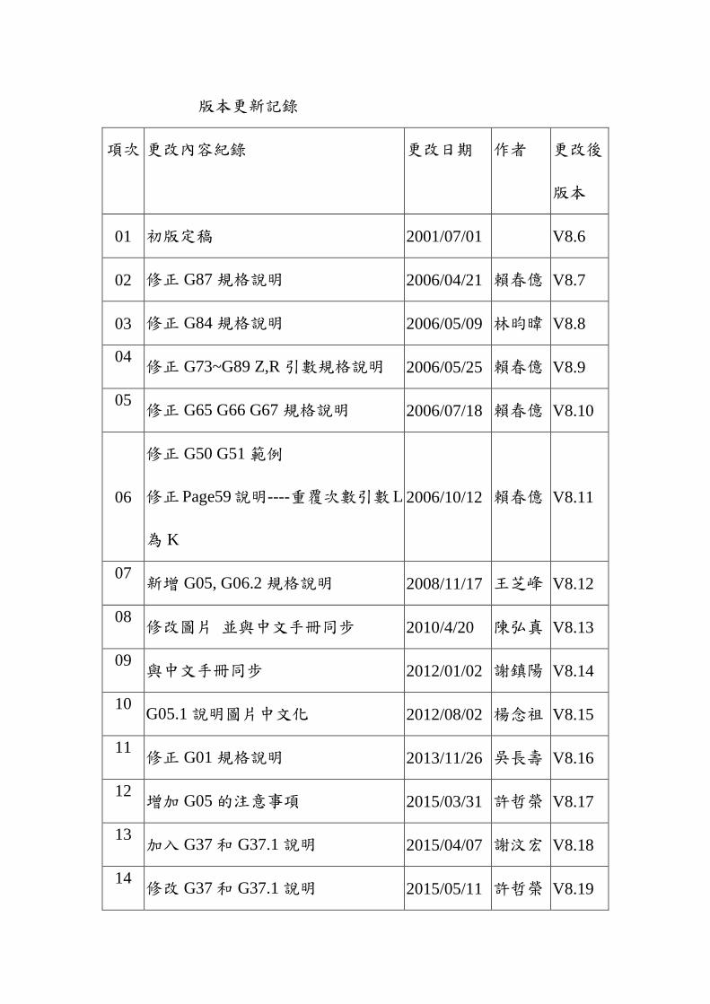
版本更新記錄
項次 更改內容紀錄 更改日期 作者 更改後
版本
01 初版定稿 2001/07/01
V8.6
02 修正 G87規格說明 2006/04/21 賴春億 V8.7
03 修正 G84規格說明 2006/05/09 林昀暐 V8.8
04 修正 G73~G89 Z,R引數規格說明 2006/05/25 賴春億 V8.9
05 修正 G65 G66 G67 規格說明 2006/07/18 賴春億 V8.10
06
修正 G50 G51範例
修正Page59說明----重覆次數引數L
為 K
2006/10/12 賴春億 V8.11
07 新增 G05, G06.2規格說明 2008/11/17 王芝峰 V8.12
08 修改圖片 並與中文手冊同步 2010/4/20 陳弘真 V8.13
09 與中文手冊同步 2012/01/02 謝鎮陽 V8.14
10 G05.1說明圖片中文化 2012/08/02 楊念祖 V8.15
11 修正 G01規格說明 2013/11/26 吳長壽 V8.16
12 增加 G05的注意事項 2015/03/31 許哲榮 V8.17
13 加入 G37和 G37.1說明 2015/04/07 謝汶宏 V8.18
14 修改 G37和 G37.1說明 2015/05/11 許哲榮 V8.19

15 增加中文標題,調整字型大小 2015/11/13 陳湘菱 V8.20

Contents 1 G Function Description ........................................................................ 1
1.1 G code list ............................................................................... 1
1.2 G code description .................................................................. 4
1.2.1 G00: POSITIONING ....................................................... 4
1.2.2 G01: LINEAR INTERPOLATION ................................ 6
1.2.3 G02/G03: CIRCULAR INTERPOLATION ................. 10
1.2.4 G02/G03: HELICAL INTERPOLATION .................... 16
1.2.5 G04: Dwell .................................................................... 18
1.2.6 G05: High Speed & High Precision Interpolation ........ 19
1.2.7 G05.1 Path Smoothing .................................................. 21
1.2.8 G06.2 NURBS Curve Interpolation .............................. 26
1.2.9 G09/G61: EXACT STOP .............................................. 29
1.2.10 G10: PROGRAMMABLE DATA INPUT ................... 30
1.2.11 G15/G16 POLAR COORDICATES COMMAND
MODE 32
1.2.12 G17/G18/G19: PLANE SELECTION .......................... 36
1.2.13 G28: RETURN TO REFERENCE POSITION ............ 37
1.2.14 G29: RETURN FROM REFERENCE POSITION ...... 38
1.2.15 G30: 2nd
, 3rd
and 4th
REFERENCE POSTION RETURN
40
1.2.16 G31: SKIP FUNCTION ................................................ 42
1.2.17 G33: THREAD INTERPOLATION ............................. 45
1.2.18 G37: AUTOMATIC TOOL LENGTH
MEASUREMENT - I .................................................................. 47
1.2.19 G37.1: AUTOMATIC TOOL LENGTH
MEASUREMENT - II ................................................................ 50
1.2.20 G40/G41/G42: CUTTER COMPENSTAION .............. 53
1.2.21 G43/G44/G49: TOOL LENGTH COMPENSATION .. 61
1.2.22 G51/G50: SCALING ..................................................... 65
1.2.23 G51.1/G50.1: PROGRAMMABLE MIRROR IMAGE
67
1.2.24 G52: LOCAL COORDINATE SYSTEM ..................... 74
1.2.25 G53: MACHINE COORDICATE SYSTEM
SELECTION ............................................................................... 78
1.2.26 G54...G59.9: WORKPIECE COORDICATE
SELECTION ............................................................................... 80

1.2.27 G64: CUTTING MODE................................................ 83
1.2.28 G65: SIMPLE CALL .................................................... 85
1.2.29 G66/G67: MACRO CALL ............................................ 86
1.2.30 G68/G69: COORDINATE ROTATION ...................... 87
1.2.31 G70/G71: UNIT SETTING OF INCH/METRIC
SYSTEM ..................................................................................... 92
1.2.32 Cycle perform function: ................................................ 93
1.2.33 G73: HIGH SPEED PECK DRILL CYCLE ................ 97
1.2.34 G74: LEFT HAND TAPPING CYCLE ...................... 100
1.2.35 G76: FINE BORING CYCLE .................................... 104
1.2.36 G81: DRILLING CYCLE ........................................... 109
1.2.37 G82: DRILLING CYCLE OF DWELL ON THE HOLE
BOTTOM .................................................................................. 112
1.2.38 G83: PECK DRILL CYCLE ....................................... 115
1.2.39 G84: TAPPING DRILLING CYCLE ......................... 118
1.2.40 G85: DRILLING CYCLE ........................................... 126
1.2.41 G86: HIGH SPEED DRILLING CYCLE................... 129
1.2.42 G87: FINE BORING CYCLE OF BACK SIDE ........ 132
1.2.43 G88: FINE BORING CYCLE OF HALF
AUTOMATION ........................................................................ 137
1.2.44 G89: BORING CYCLE OF DWELL ON THE HOLE
BOTTOM .................................................................................. 140
1.2.45 G90/G91: ABSOLUTE/INCREMENT COMMEND 143
1.2.46 G92: SETTING OF WORK COORDINATE SYSTEM
144
1.2.47 G94/G95: FEED UNIT SETTING .............................. 145
1.2.48 G96/G97: CONSTANT LINEAR VELOCITY
CONTROL ON SURFACE ...................................................... 146
1.2.49 G134: CIRCUMFERENCE HOLE CYCLE .............. 148
1.2.50 G135: ANGULAR STRAIGHT HOLE CYCLE ........ 150
1.2.51 G136: ARC TYPE HOLE CYCLE ............................. 152
1.2.52 G137.1: CHESS TYPE HOLE CYCLE...................... 154
1.2.53 Tool Function: T Code Command .............................. 156
1.2.54 Spindle Speed Function: S Code Command ............... 156
1.2.55 Cyclic Processing Function ......................................... 156

工件 工件
+R
-Z
-R
-Z
增量值時絕對值時
R點 R點
................................................................................................... 160
1.2.56 Feed Function: F Code Command .............................. 160
2 M Code Description: ........................................................................ 161

1. G Function Description
1
1 G Function Description
1.1 G code list
G code Function PS. Item Function name PS.
G00 Positioning G64 Cutting mode
G01 Linear interpolation G65 Marco call ※
G02
Circular interpolation
/Helical interpolation
(CW)
G66 Marco modal call ※
G03
Circular interpolation
/Helical interpolation
(CCW)
G67 Marco modal call
cancel ※
G04 Dwell ,exact stop G68 Coordinate rotation
G05
High speed and high
precision
interpolation
G69 Coordinate rotation
cancel
G09 Exact stop G70 Inch perform
G10 Programmable data
input G71 Mm perform
G15 Polar coordinates
command cancel G73 Peck drilling cycle
G16 Polar coordinates
command G74 Counter tapping cycle
G17 X-Y plane selection G76 Fine boring cycle
G18 Z-X plane selection G80 Canned cycle cancel
G19 Y-Z plane selection G81 Drilling cycle
G28 Return to reference
position G82
Drilling cycle of dwell
on
the hole bottom
G29 Return from
reference position G83 Peck drilling cycle
G30 2
nd ,3
rd and 4
th
reference position G84 Tapping cycle

1. G Function Description
2
return
G31 Skip function G85 Drilling cycle
G33 Thread cutting G86 High speed drilling
cycle
G40 Cutter compensation
cancel G87
Fine boring cycle of
back
side
G41 Cutter compensation
left G88
Fine boring cycle of
half automation
G42 Cutter compensation
right G89
Boring cycle of dwell
on
the hole bottom
G43
Tool length
compensation +
direction
G90 Absolute command
G44
Tool length
compensation -
direction
G91 Increment command
G49 Tool length
compensation cancel G92
Setting of work
coordinate system
G50 Scaling G94 Feed per
minute(mm/min.)
G51 Scaling cancel G95 Feed per rotation
(mm/rev.)
G50.1 Programmable mirror
image cancel G96
Constant linear
velocity control on
surface
G51.1 Programmable mirror
image G97
Constant linear
velocity control on
surface cancel
G52
Local coordinate
system
setting
G98 Return to initial point
in canned cycle
G53 Machine coordinate
system setting G99
Return to R point in
canned cycle
G54 Workpiece
coordinate system 1 G134
Circumference hole
cycle

1. G Function Description
3
selection
G59
Workpiece
coordinate system 6
selection
G135 Angular straight hole
cycle
G61 Exact stop mode G136 Arc type hole cycle
G137.1 Chess type hole cycle
SYNTEC 900M G code uses RS274D standards, and the
only differences with FANUC 0M are G70, G71
respective to G20, G21.

1. G Function Description
4
1.2 G code description
1.2.1 G00: POSITIONING
Command form:
G00 X Y Z ;
X、Y、Z: Specified point
Description:
each axles move to appointed point in no interpolation
status, X、Y、Z is the final position, use G90/G91 to design
absolute or increment value.
<Notice>: the movement mode can decide by parameter
#411
(0: linear, 1: each axle move in max speed independently)
PIC:
20 70
20
20
X
Y
Program
zero point
start point
End point
Program description:
1. first way(absolute): G90 G00 X90.0 Y40.0;

1. G Function Description
5
//use difference value between appointed point and zero
point to do straight interpolation to appointed point
2. second way(increment): G91 G00 X70.0 Y20.0;
// use difference value between appointed point and initial
point to do straight interpolation to appointed point
1. G Function Description
6
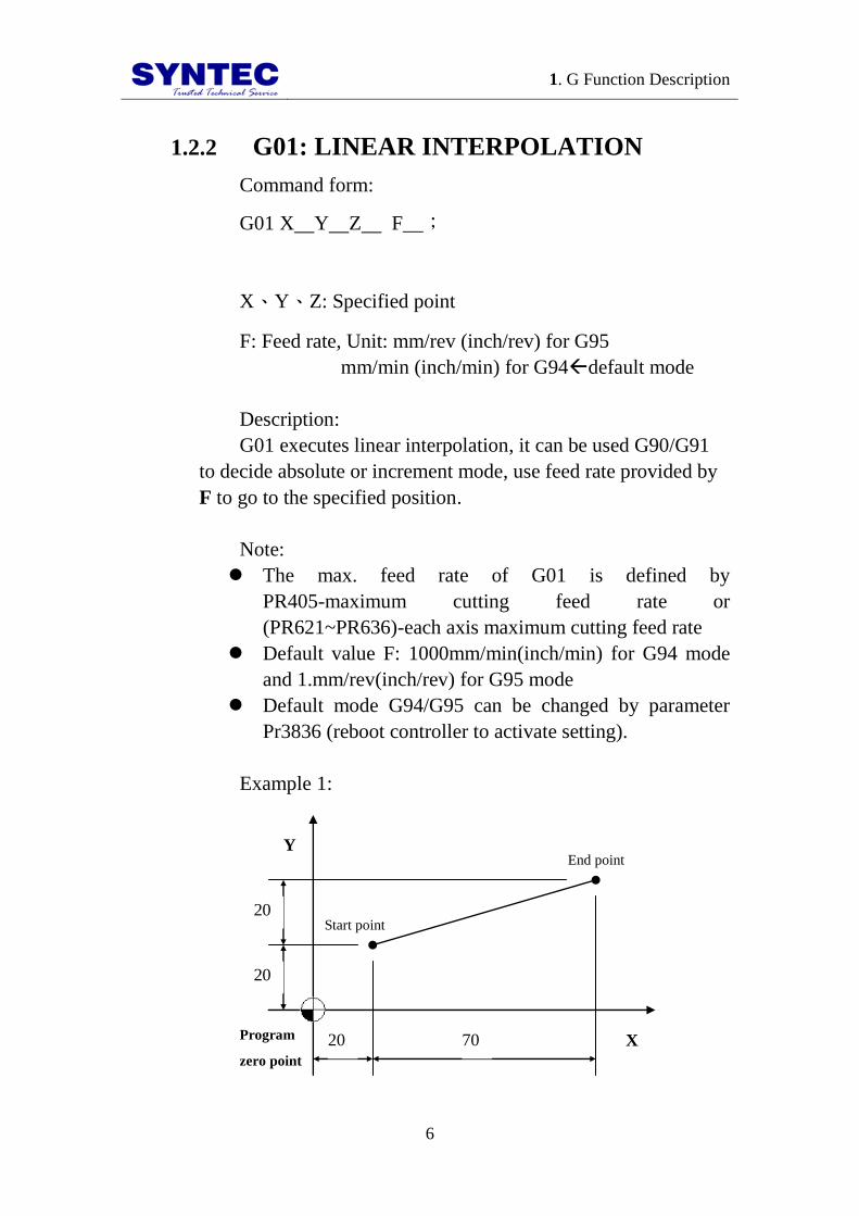
1.2.2 G01: LINEAR INTERPOLATION
Command form:
G01 X Y Z F__;
X、Y、Z: Specified point
F: Feed rate, Unit: mm/rev (inch/rev) for G95
mm/min (inch/min) for G94default mode
Description:
G01 executes linear interpolation, it can be used G90/G91
to decide absolute or increment mode, use feed rate provided by
F to go to the specified position.
Note:
The max. feed rate of G01 is defined by
PR405-maximum cutting feed rate or
(PR621~PR636)-each axis maximum cutting feed rate
Default value F: 1000mm/min(inch/min) for G94 mode
and 1.mm/rev(inch/rev) for G95 mode
Default mode G94/G95 can be changed by parameter
Pr3836 (reboot controller to activate setting).
Example 1:
20 70
20
20
X
Y
Program
zero point
Start point
End point

1. G Function Description
7
1. absolute command: G90 G01 X90.0 Y40.0;
//do linear interpolation from zero point to the specified
point(90,40)
2. increment command: G91 G01 X70.0 Y20.0;
// the tool does linear interpolation X + 70 and Y + 20 to
specified point

1. G Function Description
8
Example 2: processing example
20 35
35
10
X
Y
P0(0,0)
Thickness 10mm
P1(0,38)
P5(45,0)
P1
P2 P3
P4
Program description:
1. absolute way:
N001 G00 X0.0 Y0.0 Z10.0;//positioning to above of P0
N002 G90 G01 Z-10.0 F1000;//straight interpolation to
bottom of workpiece, speed 1000mm/min
N003 Y38.0;//P0 P1
N004 X20.0 Y45.0;//P1 P2
N005 X55.0;//P2 P3
N006 Y10.0;//P3 P4
N007 X45.0 Y0.0;//P4 P5
N008 X0.0;//P5 P0
N009 G00 Z10.0;//positioning back to above of P0
N010 M30;//program end
2. increment way

1. G Function Description
9
N001 G00 X0.0 Y0.0 Z10.0;//positioning to above of P0
N002 G91 G01 Z-20.0 F1000;//straight interpolation to
bottom of workpiece, speed 1000mm/min
N003 Y38.0;//P0 P1
N004 X20.0 Y7.0;//P1 P2
N005 X35.0;//P2 P3
N006 Y-35.0;//P3 P4
N007 X-10.0 Y-10.0;//P4 P5
N008 X-45.0;//P5 P0
N009 G00 Z20.0;//positioning back to above of P0
N011 M30;//program end
1. G Function Description
10
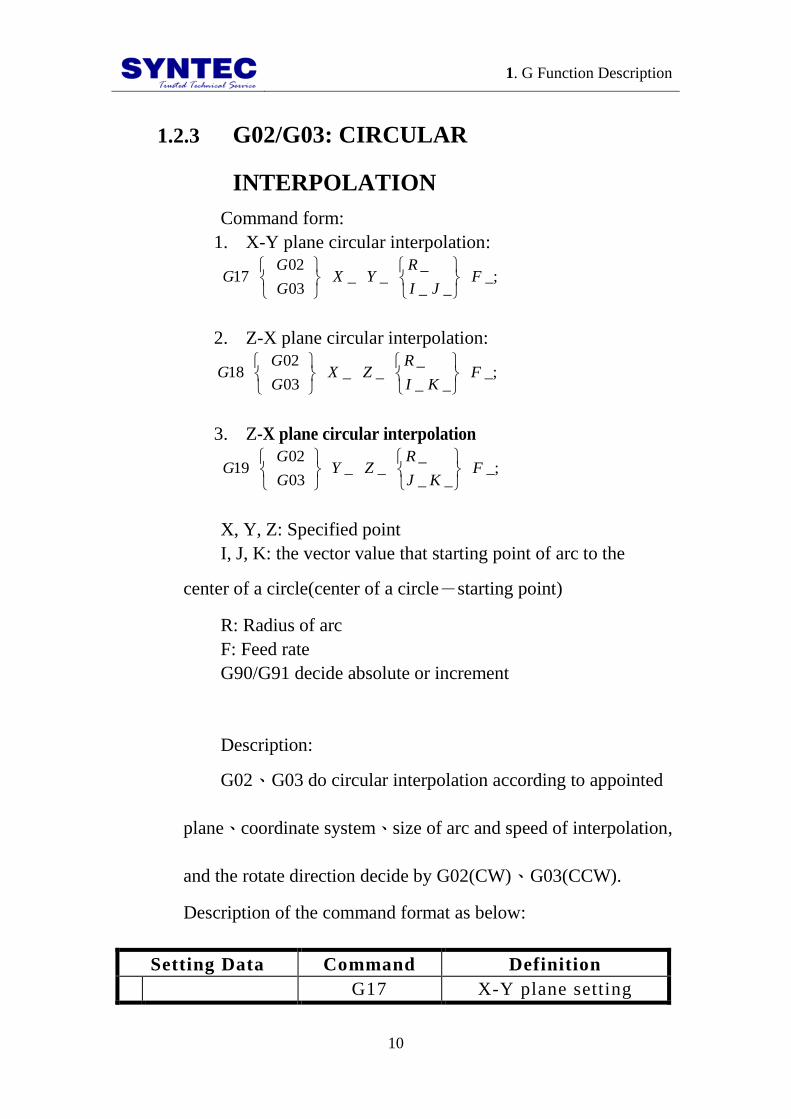
1.2.3 G02/G03: CIRCULAR
INTERPOLATION
Command form:
1. X-Y plane circular interpolation:
_;__
___
03
0217 F
JI
RYX
G
GG
2. Z-X plane circular interpolation:
_;__
___
03
0218 F
KI
RZX
G
GG
3. Z-X plane circular interpolation
_;__
___
03
0219 F
KJ
RZY
G
GG
X, Y, Z: Specified point
I, J, K: the vector value that starting point of arc to the
center of a circle(center of a circle-starting point)
R: Radius of arc
F: Feed rate
G90/G91 decide absolute or increment
Description:
G02、G03 do circular interpolation according to appointed
plane、coordinate system、size of arc and speed of interpolation,
and the rotate direction decide by G02(CW)、G03(CCW).
Description of the command format as below:
Setting Data Command Definition
G17 X-Y plane setting

1. G Function Description
11
1 Plane selection G18 X-Z plane setting
G19 Y-Z plane setting
2 Direction
G02 Clockwise direction
(CW)
G03 Counterclockwise
direction (CCW)
3 End
position
G90 Two axes of X,
Y, Z
End coordinate of arc
G91 Two axes of X,
Y, Z
Vector value from start
point to end point
4
Distance from
start point to
center of circle
Two axes of
I, J, K
Vector value from start
of arc to center of circle
Radius of arc R Radius of arc
5 Speed of feed
(feedrate)
F Feedrate along the arc
Example:
1. G02, G03 direction
X
G02
G03 Y
Z
G02
G03 X
X
G02
G03 Y
G17 G18 G19
2. I, J, K definition:

1. G Function Description
12
I
Start position
End position
J
Center
X
Y
`
`
a. arc of X-Y plane
Start position
End position
I K
Center
X
Z
`
`
b. arc of Z-X plane
Center
Stast position
End position
J K
Y
Z
`
`
c. arc of Y-Z plane

1. G Function Description
13
3. how to use R:
When θ≦180 degree, R is positive.
;0.25__03
02RYX
G
G
When 180 degree<θ<360 degree, R is
negative.
;0.25__03
02
RYXG
G
When θ=360 degree, only use I、J、K.
Start point
α >180
∘
α ≦180
∘
Center #1
Center #2
Arc α ≦180.
(R positive)
Arc α >180.
(R negative)
Program example 1:
End point
S
tar
tin
g
po
int
c
e
n
t
G90 G00 X5500 Y4000;//positioning to start point of arc
G17 G90 G03 X1500 Y4000 I-3000 J-1000 F200;

1. G Function Description
14
//absolute command
(G17 G91 G03 X-4000 Y2000 I-3000 J-1000 F200;
//increment command)
1. G Function Description
15
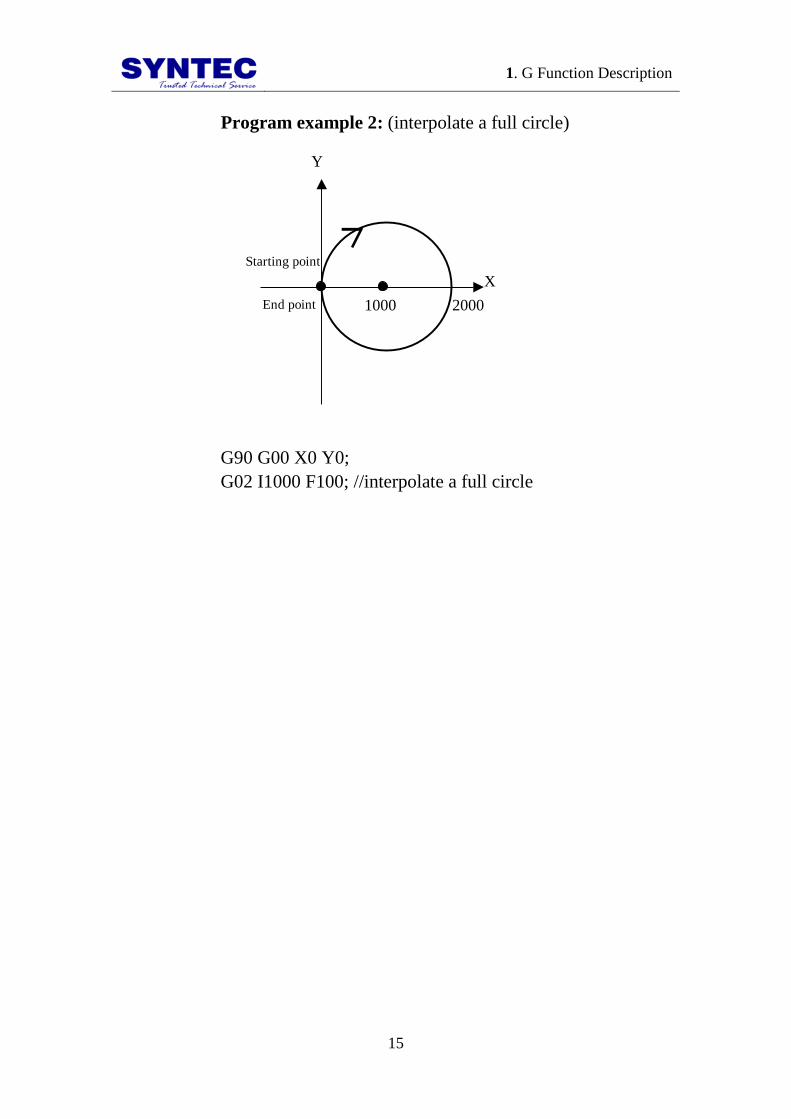
Program example 2: (interpolate a full circle)
X
Y
Starting point
End point 1000 2000
G90 G00 X0 Y0;
G02 I1000 F100; //interpolate a full circle

1. G Function Description
16
1.2.4 G02/G03: HELICAL INTERPOLATION
Command form:
(1)
_;___
___
03
0217 FZ
JI
RYX
G
GG
X, Y: end position of arc;
Z: end position of straight line;
R: radius of arc;
I, J: center position of arc;
F: speed of tool feed(feed rate);
(2)
_;___
___
03
0218 FY
KI
RZX
G
GG
X, Z: end position of arc;
Y: end position of straight line;
R: radius of arc;
I, K: center position of arc;
F: speed of tool feed(feed rate);
(3)
_;___
___
03
0219 FX
KJ
RZY
G
GG
Y, Z: end position of arc;
X: end position of straight line;

1. G Function Description
17
R: radius of arc;
J, K: center position of arc;
F: speed of tool feed(feed rate);
Description:
When the 3rd
axis which is vertical to arc plane moves,
G02/G03 is to be helical interpolation. The choice of helical
interpolation is the same as circular interpolation. Helical
interpolation uses G code(G17/G18/G19) to decide which plane
to do circular interpolation.
G17 form: synchronously with arc of X-Y plane.
G18 form: synchronously with arc of Z-X plane.
G19 form: synchronously with arc of Y-Z planeExample:
R1000
900 End point
Start point
F600
Z
X
Y
1000
Program description:
G17 G03 X0.0 Y1000.0 R1000.0 Z900.0 F600;
// synchronously with arc of X-Y plane (CCW), do helical
interpolation with feedrate 600mm/min

1. G Function Description
18
1.2.5 G04: Dwell
Command form:
;_
_04
P
XG
X: specific time (decimal point permitted 0.001~
9999.999s)
P: specific time (decimal point not permitted)
Description:
By specifying a dwell, the execution of the next block is
delayed by the specified time. In addition, a dwell can be
specified to make an exact check in the cutting mode.
Program example:
G04 X2500;//delay 2.5 sec
G04 X2.5;//delay 2.5 sec
G04 P2500;//delay 2.5 sec
G04 P2.5;//delay 2 sec (decimal point not permitted)
1. G Function Description
19
1.2.6 G05: High Speed & High Precision
Interpolation
Command form:
ioninterpolatHSHPStart//;
5
4
3
2
1
10000
PG05
G01 X Y Z F__;
G02 X Y Z R ;
G00 X Y Z ;
G05 P0; // Cancel HSHP interpolation
P: Multiple motion parameters
X, Y, Z: Specific coordinate point
F: Max feedrate (mm/min)
Description:
G05 provides one default parameter, P10000, and five other
parameters, P1~P5, for users. Interpolation commands execute
the mode of smoothing curve by processing program. G90/G91
decides absolute or increment mode. Feedrate is decided by F
code for high speed & high precision interpolation.
Condition:
On high speed & high precision interpolation (G05 P )
mode, M code and MPG simulation of negative
direction are invalid.
On high speed & high precision interpolation (G05 P )
mode, if cutter compensation(G40/G41/G42) and tool
length compensation (G43/G44/G49) are used, the

1. G Function Description
20
program can cancel G05 mode until G40/G41/G42 or
G43/G44/G49 ending. It is not recommended to do that
unless necessary.
On high speed & high precision interpolation (G05 P )
mode, M30 or M99 is needed to be added in the end of
program.

1. G Function Description
21
Example:
End point
Start point
G01
G05 smoothing path
X
Y
G0 X3. Y4. Z0.
G05 P10000 //Start high speed & high precision
interpolation
G01 X3.8 Y6.1 F5000.
X4.6 Y7.
X5.4 Y6.1
X6.1 Y4.
X6.9 Y1.9
X7.7 Y1.
X8.5 Y1.9
X9.3 Y4.
X10. Y6.1
G05 P0 // Cancel high speed & high precision interpolation
M30
1.2.7 G05.1 Path Smoothing
Command form:
G5.1 Q1 E_ :Start path smoothing function
:
G5.1 Q0 :Close path smoothing function

1. G Function Description
22
Q:Switch to start/Close the smoothing function
E:The maximum allowable path error while smoothing. Use
“mm” as the unit.
Descriptions
1. If command is inadequate (ex: Q or E unspecified), it will
be ineffective.
2. G90 and G91can both be used in conjunction with G05.1.
3. Path smoothing is only effective on command G01
between G5.1 Q1 E and G5.1 Q0.
4. Under G5.1 mode, press single block stop will not
necessarily stop the process at the end of the block.
Conditions:
1. Under G61/G63 mode, Commands to start path
smoothing (G5.1) are prohibited. Otherwise, system will
issue the alarm.
2. Under G5.1 mode, if G61/G63 is performed, path
smoothing will stop. Until system leaves G61/G63 mode,
path smoothing function will be restart automatically.
3. Under G5.1, If command G01 is after tool length
compensation command(G43) or coordinate
transformation command(G54), path smoothing will not
be performed. Afterwards, G01 command returns to
perform path smoothing.
Figure

1. G Function Description
23
Example 1
N001 G05.1 Q1 E0.01 //Start path smoothing function,
allowable error: 10um
N002 G90 G01 F2000
N003 X-0.002 Y-0.001 //the following commands perform path
smoothing function
N004 X-0.003 Y-0.003
N005 X-0.004 Y-0.005
N006 X-0.005 Y-0.007
N007 X-0.007 Y-0.008
N008 X-0.008 Y-0.009
N009 X-0.011 Y-0.010
N010 X-0.013 Y-0.012
N011 X-0.014 Y-0.013
N012 X-0.015 Y-0.015
N013 X-0.016 Y-0.018
N014 G05.1 Q0 // close path smoothing function
N015 M30 //program ends
Example 2
N001 G05.1 Q1 E0.01 //Start path smoothing function,
allowable error: 10um
N002 G91 G01 F2000
N003 X-0.002 Y-0.001 //the following commands perform path
smoothing function

1. G Function Description
24
N004 X-0.001 Y-0.002
N005 X-0.001 Y-0.002
N006 X-0.001 Y-0.002
N007 X-0.002 Y-0.001
N008 X-0.001 Y-0.001
N009 X-0.003 Y-0.001
N010 X-0.002 Y-0.002
N011 X-0.001 Y-0.001
N012 X-0.001 Y-0.002
N013 X-0.001 Y-0.003
N014 G05.1 Q0 // close path smoothing function
N015 M30 //program ends

1. G Function Description
25
Example 3
G5.1 Q1 E0.1 // Start path smoothing function, allowable error:
100um
G91 G01 F2000 // the following commands perform path smoothing
function
X -0.005
:
G43 H3 //G43command
Y -0.005 // this command doesn’t perform path smoothing
function
X -0.005 // restart path smoothing function
:
M30 //program ends
Example 4
G5.1 Q1 E0.05 // Start path smoothing function, allowable
error: 50um
G90 G01 F2000 // the following commands perform path
smoothing function
X-0.005 Y0.
:
X-0.1 Y-0.01
G61 //start G61 mode and close path smoothing
function
X-0.1 Y-0.02 //the following commands do not perform
path smoothing function
:
X0.005 Y0.
G64 //close G61
X0.005 Y0.01 //restart path smoothing function
:
M30 //program ends

1. G Function Description
26
1.2.8 G06.2 NURBS Curve Interpolation
Command form
G05 P10000;// Start high speed & high precision
interpolation
:
G06.2 P K X Y Z R F__;//NURBS curve
interpolation
K X Y Z R ;
K X Y Z R ;
K X Y Z R ;
K ;
K ;
K ;
K ;
:
G05 P0;// Cancel high speed & high precision interpolation
P:Order of NURBS curve ( 2 ~ 4 ), default value is 4
if it is leaved blank.
K:NURBS node value of curve
X、Y、Z:NURBS control-point coordinates
R:NURBS curve weight ( 0.001 ~ 1000 ), default value
is 1.0 if it is leaved blank.
F:The maximum feedrate of NURBS curve (mm/min),
default value is that of previous curve if it is leaved blank.
Description:
G06.2 cutting command executes NURBS curve
interpolation according to the program. G90/G91 determines
whether absolute or incremental mode is used. The cutting

1. G Function Description
27
feedrate of NURBS curve interpolation is set by “F”
function.

1. G Function Description
28
Condition
Single block Execution and hand-wheel simulation in negative
direction are not supported.
Definition of NURBS curve:
A NURBS curve can be expressed as the formula shown below :
p:Order of NURBS curve rank
1 1
11
,..., , ,..., , ,...,p n p
pp
U a a u u b b
:node vector of NURBS curve
1i iu u , 1m n p
iP:coordinates of NURBS curve control point
iw :weight of NURBS curve
The definition of NURBS basis function is:
1
,
1
, , 1 1, 1
1 1
1,( ) ,
0,
( ) ( ) ( ).
i i
i p
i pii p i p i p
i p i i p i
u u uN u
otherwise
u uu uN u N u N u
u u u u
Example:
N001 G0 X0.0 Y0.0 Z0.0
N002 G05 P10000 //Start high speed & high precision
interpolation
N003 G06.2 P3 K0.0 X0.0 Y0.0 Z0.0 R1.0 F5000.
//execute NURBS curve interpolation
N004 K0.0 X0.0 Y5.0 Z0.0 R1.0
N005 K0.0 X5.0 Y5.0 Z0.0 R1.0
N006 K1.0
N007 K1.0
N008 K1.0
N009 G05 P0 // high speed & high precision interpolation off

1. G Function Description
29
1.2.9 G09/G61: EXACT STOP
Command form:
G09 X__ Y__ Z__ ;
G61 ;
X, Y, Z: position of exact stop
Description:
when cut the corner, because tool moves too fast or servo
system delays, tool can not cut the exact shape of corner, but
when you need to cut high precision rectangular, you can use
G09 or G61 to make it, it slow down the tool when approach to
corner, when reach to the specified position (in CNC parameter
range), it will run the next block. G09 exact stop only effected in
one block which has G09; G61 exact stop effected each cutting
command (G01~G03) after G61, until G62 or G63 or G64 is
specified.
Notice:
G01 check window: parameter 421-440
G00 check window: parameter 461-480
Example:
Position check
Y
Next block
Previous block
X
Tool
path without G09/G61 path with G09/G61

1. G Function Description
30
1.2.10 G10: PROGRAMMABLE DATA INPUT
Command form:
;__
13
12
11
10
10 RP
L
L
L
L
G
L10: for tool length(H) geometric compensation value
L11: for tool length(H) wear compensation value
L12: for tool diameter(D) geometric compensation value
L13: for tool diameter(D) wear compensation value
P: tool NO.
R: compensation value(data of tool length or tool diameter)
Description:
G10 command: it can directly use program command to
enter tool compensation value.
In absolute mode (G90), value of G10 is the new
compensation value; in increment mode (G91), value of G10 is
the sum of the value of the moment with the new compensation
value.
Example:
OFSG
OFSW
Reference
position

1. G Function Description
31

1. G Function Description
32
1.2.11 G15/G16 POLAR COORDICATES
COMMAND MODE
Command form:
commandcoordinate//Polar
commandcoordinatepolar//Cancel
modecoordinatepolar//Start
__
;15
__
;16
YX
G
G
G
:
:
X: polar coordinate radius
Y: polar coordinate angle( “+” for CW, ”-” for CCW)
Description:
start polar coordinate mode in first line, G16 for polar
coordinate command start, G15 for polar coordinate command
cancel, it can use polar coordinate mode to enter position(radius
and angle), G90/G91 can specify in it. First address is radius,
second address is angle. Absolute or increment is decided by
G90 or G91, G90 is absolute, G91 is increment, in absolute mode,
the increase of radius or angle from origin point; in increment
mode, angle or radius total from the last radius or angle.

1. G Function Description
33
Example:
1. when polar coordinate zero point is the same as working
coordinate
Angle Actual position
Command point
Radius
a. When angle is specified
with an absolute command
Angle Actual position
Command point
Radius
半徑
b. when angle is specifed with
an increment command
2. when polar coordinate zero point is in normal position
Actual position
Command point
Angle
Radius
半
a. When angle is specified
with an absolute command
Angle
Actual position
Command point
Radius
b. when angle is specifed with
an increment command

1. G Function Description
34
Program example:
X
120
130 Second hole
100 120∘
120∘
Y
First hole
Third hole
Thickness 10 mm
1. Absolute command:
N001 T1 S1000 M03;
//NO.1 tool(diameter 10 mm drill), spindle 1000rpm (CW)
N002 G17 G90 G16;
//X-Y plane, absolute mode, start polar coordinate mode
N003 G99 G81 Z-12.0 R2.0 F600 K0;
//do drilling cycle, depth 12mm, feedrate 600mm/min, back
to R point when finish
N004 X100.0 Y90.0;
//specified a distance 100mm, angle 90 degree(first hole)
N005 Y210.0;
//specified a distance 100mm and angle 210 degree, from the
origin point(second hole)
N006 Y330.0;
//specified a distance 100mm and angle 330 degree, from the
origin point(third hole)

1. G Function Description
35
N007 G15 G80 M05;
//polar coordinate mode cancel, cycle cancel, spindle stop
N008 M30;//program end
2. Increment command:
N001 T1 S1000 M03;
// NO.1 tool(diameter 10 mm drill), spindle 1000rpm (CW)
N002 G17 G90 G16;
// X-Y plane, absolute mode, start polar coordinate mode
N003 G99 G81 Z-12.0 R2.0 F600 K0;
// do drilling cycle, depth 12mm, feedrate 600mm/min, back
to R point when finish
N004 X100.0 Y90.0;
//specified a distance 100mm, angle 90 degree(first hole)
N005 G91 Y120.0 K2;
//increment command, angle totals 120 degree from last
point (second hole)
N006 Y120.0;
//increment command, angle totals 120 degree from last
point (third hole)
N007 G15 G80 M05;
// polar coordinate mode cancel, cycle cancel, spindle stop
N008 M30;//program ends
1. G Function Description
36
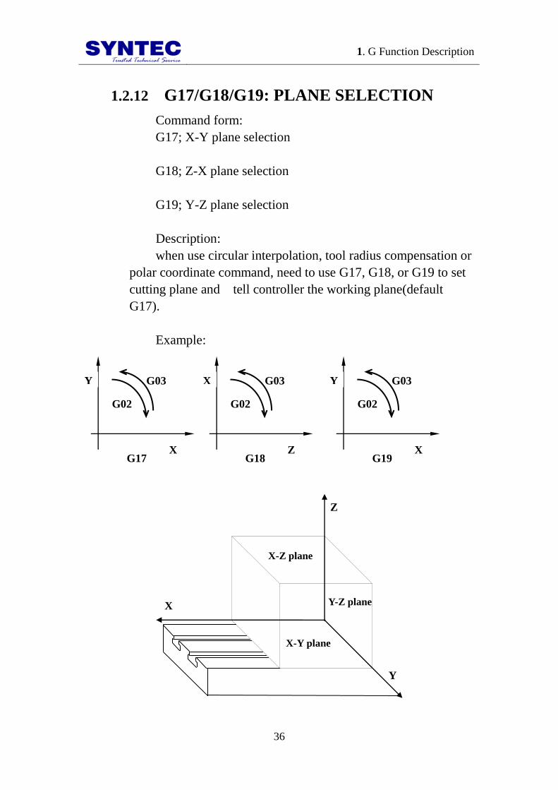
1.2.12 G17/G18/G19: PLANE SELECTION
Command form:
G17; X-Y plane selection
G18; Z-X plane selection
G19; Y-Z plane selection
Description:
when use circular interpolation, tool radius compensation or
polar coordinate command, need to use G17, G18, or G19 to set
cutting plane and tell controller the working plane(default
G17).
Example:
G03 G03 G03
X
G02
Y
Z
G02
X
X
G02
Y
G17 G18 G19
Y-Z plane X
Z
Y
X-Z plane
X-Y plane
1. G Function Description
37
1.2.13 G28: RETURN TO REFERENCE
POSITION
Command form:
G28 X Y Z ;
X, Y, Z: mid-point position (absolute value in G90 mode,
increment value in G91 mode)
Description:
it can return to reference position or return to origin point,
in order not to let the tool crush, it will use G00 mode to move
from present position, it will move to the specified safety
mid-point first and then return to origin point or reference point.
<Note> this command usually use in auto tool exchange.
For safety, before doing G28, must cancel tool compensation
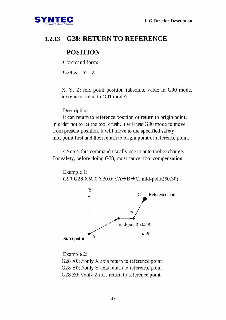
Example 1:
G90 G28 X50.0 Y30.0; //ABC, mid-point(50,30)
Start point
mid-point(50,30)
Reference point
A
B
C
X
Y
Example 2:
G28 X0; //only X axis return to reference point
G28 Y0; //only Y axis return to reference point
G28 Z0; //only Z axis return to reference point

1. G Function Description
38
1.2.14 G29: RETURN FROM REFERENCE
POSITION
Command form:
G29 X Y Z ;
X, Y, Z: specified coordinate;(absolute value in G90 mode,
increment value in G91 mode)
Description:
G29 can let tool from reference point through mid-point to
specified point after setting G28. Notice that G29 can not use
alone, because G29 does not specify mid-point, G29 use the
mid-point from G28, therefore, before do G29 must do G28 first.
Under G90, the specified point is the absolute coordinate;
under G91, it is the increment distance from mid-point to
specified point.
Example:
D A
B
C
Reference point
mid-point(20,30)
X
Y
Specified point(40,0)
1. Absolute command:
N001 G90 G28 X20.0 Y30.0;
//ABC, mid-point(20,40), in absolute command mode
N002 M06;//change the tool
N003 G29 X40.0 Y0.0;
// CBD, the specified point is absolute coordinate

1. G Function Description
39
2. Increment command:
N001 G91 G28 X20.0 Y40.0;
//ABC, mid-point(20,40), in increment command mode
N002 M06;//change the tool
N003 G29 X40.0 Y-40.0;
//CBD, the specified position is the increment value
from mid-point to specified point

1. G Function Description
40
1.2.15 G30: 2nd
, 3rd
and 4th
REFERENCE
POSTION RETURN
Command form:
G30 Pn X Y Z ;
X、Y、Z: mid-point coordinates;(absolute value under G90,
increment value under G91)
Pn: Specified reference point(parameter #2801 ~ #2860)
P1: mechanical origin point;
P2: second reference point;
P_: default is P2;
Description:
for the convenience that change tool and check, we use
parameter to set a reference point to suitable position, it can let
tool need not return to mechanical zero point, increase efficiency
in changing the tool, the usage of this command is the same as
G28 only expect returned point. Floating reference position
return command, usually use in the position of automatically
change the tool differ from the origin point. Movement mode
G00.
<Notice> usually this command use in automatically change
the tool, for safety, before do G30, need to cancel the tool
compensation function.
Example:

1. G Function Description
41
A (60,10)
B (75,25)
C (15,10)
Third reference point
950
9
9(
Second reference point
950
9
9(
Mechanical origin point
X
Y
950
9
9(
workpiece
950
9
9(
Program description: presume tool is in A (60,10)
1. to second reference point
G30 P2 X75.0 Y25.0;//AB 2nd
reference point
2. to third reference point
G30 P3 X15.0 Y10.0;//AC 3rd
reference point

1. G Function Description
42
1.2.16 G31: SKIP FUNCTION
Command form:
G31 X__ Y__ Z__ F__;
X, Y, Z: specified point
F: feedrate
Description:
skip command use in a unknown program point, and it
specify that point, when measurement runs into impede, when
machine get skip signal, LADDER C BIT ON, G31 will record
the present mechanical position and interrupt motion of G31, run
next block.
Example 1: incremental command(G91)
Skip signal is input here
(contact point) 100.0
.0.0
100.0
.0.0 Actual motion
.0.0 Motion without skip signal
.0.0
Program description:
N001 G31 G91 X100.0 F100; //original motion until run
into impede
N002 Y100.0;//use contact point to be opposite coordinate,
change path to specified position, it does not wait to the
finished of front block

1. G Function Description
43
Example 2: absolute command for 1 axes(G90)
Skip signal is input here
Y100.0
X200.0 Zero point
.0.0 Actual motion
Motion without skip signal
Program description:
N001 G31 G90 X200.0 F100; //original path until running
into impede
N002 X200.0 Y100.0; //use zero point to be the relative
coordinate to change the path to the specified position, and it
does not wait to the finished of front block.
Example 3: absolute command for 2 axes(G90)
Skip signal is input here
(100,0) Zero point Actual motion
Motion without skip signal
(130,70)
Program description:
N001 G31 G90 X100.0 F1000; // original path until
running into impede

1. G Function Description
44
N002 X130.0 Y70.0; // use zero point to be opposite
coordinate to change the path to specify position, it does not
wait to the finished of front block

1. G Function Description
45
1.2.17 G33: THREAD INTERPOLATION
Command form:
G33 Z F ;
Z: Absolute command (G90), coordinates of Z axis for end
point;
Incremental command (G91), for length of thread in axis
direction;
F: the thread of a screw (0.01mm);
Description:
When spindle turned, tool feeds in Z axis direction at the
same time. After repeating many times, there is inertia lag of the
spindle rotation at thread interpolation finishing. They will
produce somewhat incorrect leads at start and end points of a
thread cut. In order to compensate this, thread cutting length
should be specified longer than required, in thread interpolation,
limit of spindle speed(R) is:
leadthread
feedrateMaxspeedspindle1 R
R: spindle speed(rpm)
Thread lead(F): mm or inch
Feedrate: mm/min or inch/min
Notes:
Max feedrate can be setting by parameter #405.
Acceleration and deceleration time of thread interpolation
can be setting by parameter #409.

1. G Function Description
46
Example:
Z
X
F
Tool
Start point
End point
Program form:
G33 Z10.0 F1.5 ;
//thread cutting at a pitch of 1.5mm, the end is at Z axis
10mm

1. G Function Description
47
1.2.18 G37: AUTOMATIC TOOL LENGTH
MEASUREMENT - I
Command form:
G37 Z_ [R_] [D_] [F_] [P_] ;
Z: Absolute command for end point of Z in program
coordinates.
R: Measuring distance, incremental value from Z position.
Value of Pr4055 will be used if R is not defined.
D:Probe overtravel distance. Value of Pr4056 will be used if
D is not defined.
F: Measuring federate. Value of Pr4057 will be used if F is
not defined.
P: Reference point P. Value of Pr4058 will be used if P is
not defined. This action of reference point return will not be
executed if Pr4058 is used and is not set 1~4.
Description:
3. Return to P reference point with G30. G30 will not be
executed if
P is not defiend.
4. Rapid move Z to starting point.
5. Move Z to probe starting point with G31
Initial Point
Starting Point
Z position
Starting point is lower than initial point
Starting Point
Initial Point
Z position
Starting point is higher than initial point
Probe starting point
Probe ending point
Probe starting point
Probe ending point

1. G Function Description
48
6. Move Z to probe ending point with G31, and proceed
with tool
length measurement.
7. Automatic tool length measurement complete, the tool
length
shall be defined to corresponding tool automatically.
Note:
1. Start from:
-SUPER/10s/20s:10.116.10C
-11s/21s:2.2.3
2. Please install the probe before the automatic tool
measurement. It is recommended to insert the probe location to
reference point P via Pr2801~2860.
3. The override is defined a 100% during automatic tool
measurement.
4. The MPG offset of Z will be reset once complete the
tool length measurement.
Alarms
5. [MAR-330 Z min. coordinate set error alarm!] shall
occur if Z is not defined.
6. [MAR-333 Z start point error alram!] shall occur if Z
initial point is lower than Z starting point.
7. [MAR-334 Without issue H code before G code tool
length measurement] shall occur if H word is not defined before
automatic tool measurement.
8. [MAR-335 measure position setting error, measure
signal has being triggered] shall occur if probe signal activated
during Z axis move from starting point to probe starting point.
9. [MAR-336 measure position setting error, measure
signal hasn't being triggered] shall occur if probe signal is not
activated once Z axis reach probe ending point.
Program form:

1. G Function Description
49
G30 P2 X75.0 Y25.0; // return to reference point 2
M06 T1; // change to T1
H1; // define the tool length
compensation H1
G37 Z-150; // move Z axis to -150.
M06 T2; // change to T2
H2; // define the tool length
compensation H2
G37 Z-150; // move Z axis to -150.
M06 T3; // change to T3
H3; // define the tool length
compensation H3
G37 P2 Z-200.; // return to reference point 2, move Z to
-200.

1. G Function Description
50
1.2.19 G37.1: AUTOMATIC TOOL LENGTH
MEASUREMENT - II
Command form:
G37 [Z_] [R_] [F_] [P_] [Q_];
Z: Absolute command for end point of Z in mechanical
coordinates. Value of Pr4057 will be used if Z is not defined.
R: Measuring distance, incremental value from Z position.
Value of Pr4055 will be used if R is not defined.
F: Measuring federate. Value of Pr4057 will be used if F is
not defined.
P: Reference point P. Value of Pr4058 will be used if P is
not defined. This action of reference point return will not be
executed if Pr4058 is used and set to 0.
Q: Safety point. The control shall retract Z to machine zero
if Q is not defined.
Description:
1. M90 enable the mist function
2. Return to P reference point with G30. G30 will not be
executed if P is not defined.
1. Rapid move Z to starting point.
Initial Point
Starting Point
Starting point is lower than initial point
Starting Point
Initial Point
Starting point is higher than initial point
Z position Z position
signal activated Z’ signal activated Z’

1. G Function Description
51
2. M91 disable the mist function
3. Move Z to defined Z position with G31
4. Retract Z axis for 1mm with G00 once probe signal
activated
5. Move Z to defined Z position with G31 F50, and
proceed with tool length measurement.
6. Automatic tool length measurement complete, the tool
length shall be defined to corresponding tool automatically.
7. Return Z axis to safety point or machine zero.
Note:
1. Start from:
-SUPER/10s/20s:10.116.10C
-11s/21s:2.2.3
2. Please install the probe before the automatic tool
measurement. It is recommended to insert the probe location to
reference point P via Pr2801~2860.
3. The override is defined a 100% during automatic tool
measurement.
4. The MPG offset of Z will be reset once complete the
tool length measurement.
Alarms
1. [MAR-330 Z min. coordinate set error alarm!] shall
occur if Z is not defined.
2. [MAR-333 Z start point error alram!] shall occur if Z
initial point is lower than Z starting point.
3. [MAR-334 Without issue H code before G code tool
length measurement] shall occur if H word is not defined before
automatic tool measurement.
4. [MAR-336 measure position setting error, measure
signal hasn't being triggered] shall occur if probe signal is not
activated once Z axis reach probe ending point.
Program form:
G30 P2 X75.0 Y25.0; // return to reference point 2

1. G Function Description
52
M06 T1; // change to T1
H1; // define the tool length
compensation H1
G37.1 Z-150; // move Z axis to -150.
M06 T2; // change to T2
H2; // define the tool length
compensation H2
G37.1 Z-150; // move Z axis to -150.
M06 T3; // change to T3
H3; // define the tool length
compensation H3
G37.1 P2 Z-200.; // return to reference point 2,
move Z to -200.

1. G Function Description
53
1.2.20 G40/G41/G42: CUTTER
COMPENSTAION
Command form:
_;__42
41ZYX
G
G
G40;
G41: cutter compensation left.
G42: cutter compensation right.
G40: cutter compensation cancel.
X, Y: the end coordinate of each axis.
D: code for specifying as the cutter compensation value.
Description:
In general, when the tool is moved, if tool center is cutting
along the workpiece, and the tool radius is overcut. In cutter
compensation, the tool moved, the tool path can be shifted by the
radius of tool. It can let the shape which is after process is equal
with layout. Therefore we can enter the size of layout, and match
this function, to get the right size of workpiece, we can ignore
tool radius in the program.
Example:
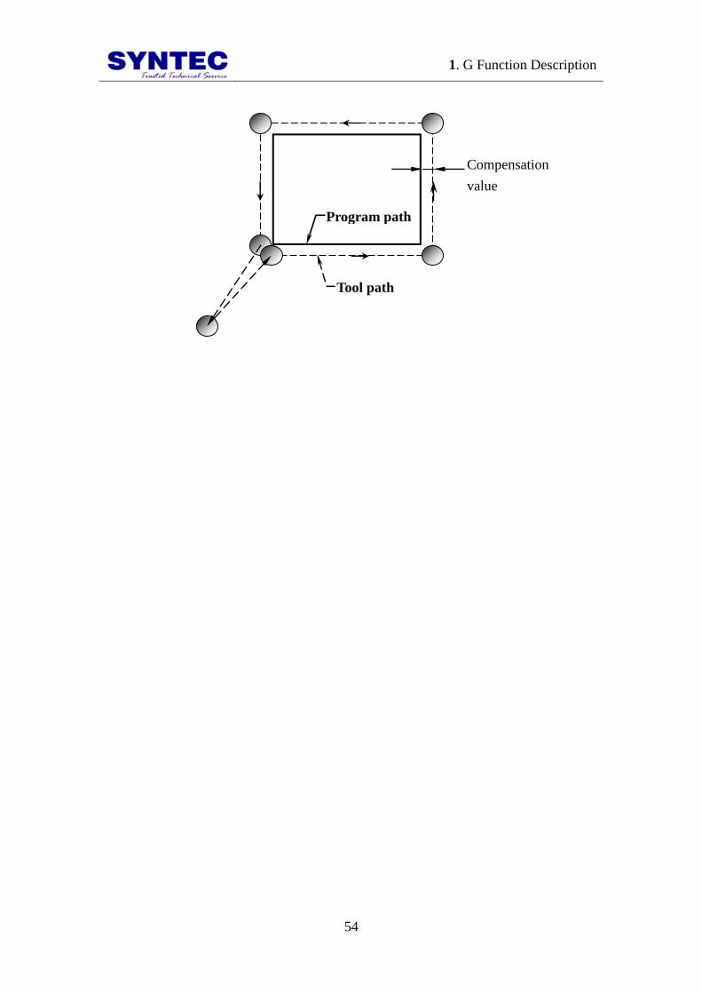
1. Cutter compensation:
1. G Function Description
54
Program path
Tool path
Compensation
value

1. G Function Description
55
2. Direction decision of cutter compensation:
G42
G41
G40
Compensation
value Positive Negative
G41
Compensatio
n
left
Compensatio
n
right
G42
Compensatio
n
right
Compensatio
n
left
G41 CW
a. G41-outline cut (CW)
CCW
G41
b. G41-inline cut (CCW)
G42
CCW
c. G42-outline cut (CCW)
CW
G42
d. G42-inline cut (CW)

1. G Function Description
56
3. cutter compensation of corner interpolartion:
When the corner: 90∘≦α<180∘
i. straight line straight line
α
Programmed path
Tool center path
ii. straight line arc
L
Tool center path
S
α
Programmed path r
C
iii. arc straight line
r
α
Programmed path
Tool center path
r
L
C S
iv. arc arc
r
α
Programmed path r
L
C
S L C
Tool center path

1. G Function Description
57
When corner α<90∘
v. straight line strainght line
L
:
α
r L
:
Programmed path
Tool center path
S
L
:
r
vi. straight line arc
L
:
α
r L
:
Programmed path Tool center path
S
L
:
r
C
:
vii. arc straight line
L
:
α
r L
:
Programmed path
Tool center path
S
L
:
r C
:
1. G Function Description
58
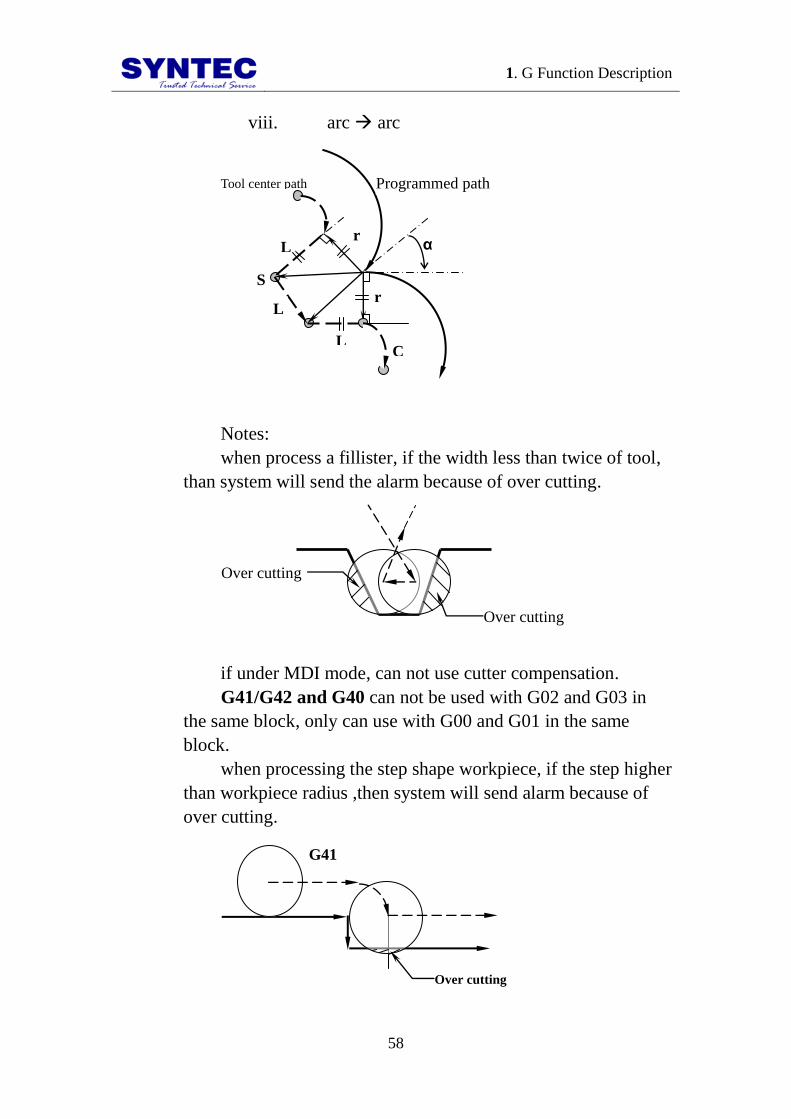
viii. arc arc
L
:
α
r L
:
Programmed path
S
L
:
Tool center path
r
C
:
Notes:
when process a fillister, if the width less than twice of tool,
than system will send the alarm because of over cutting.
Over cutting
Over cutting
if under MDI mode, can not use cutter compensation.
G41/G42 and G40 can not be used with G02 and G03 in
the same block, only can use with G00 and G01 in the same
block.
when processing the step shape workpiece, if the step higher
than workpiece radius ,then system will send alarm because of
over cutting.
G41
Over cutting

1. G Function Description
59
Program example:
Program zero
point
X
Y
A
A
B
C
D
E F
A
G
H
M
Program description:
N001 T1 S1000 M03;//tool NO.1(diameter 10mm), spindle
1000rpm (CW)
N002 G00 X0.0 Y0.0 Z10.0 ; //positioning above
programmed zero point
N003 M08;//open cutting liquid
N004 G90 G01 Z-10.0 F600; //linear interpolation to
bottom of workpiece, feedrate 600mm/min
N005 G42 Y24.0 D01;//cutter compensation left, program
zero pointA
N006 G03 X9.0 Y30.0 R10.0;//AB circular interpolation
(CCW)

1. G Function Description
60
N007 G02 X30.0 Y9.0 R15.0;//BC circular interpolation
(CW)
N008 G03 X30.0 Y-9.0 R10.0 ; //CD circular
interpolation (CCW)
N009 G02 X9.0 Y-30.0 R15.0 ; //DE circular
interpolation (CW)
N010 G03 X-9.0 Y-30.0 R10.0 ; //EF circular
interpolation (CCW)
N011 G02 X-30.0 Y-9.0 R15.0 ; //FG circular
interpolation (CW)
N012 G03 X-30.0 Y9.0 R10.0 ; //GH circular
interpolation (CCW)
N013 G02 X-9.0 Y30.0 R15.0 ; //HM circular
interpolation (CW)
N014 G03 X0.0 Y24.0 R10.0 ; //MA circular
interpolation (CCW)
N015 G00 Z10.0;//Z axis rise, return to start point
N016 G40 X0.0 Y0.0;//cutter interpolation cancel, return
to start point
N017 M09;//cutting liquid OFF
N018 M05;//spindle stop
N019 M30;//program end

1. G Function Description
61
1.2.21 G43/G44/G49: TOOL LENGTH
COMPENSATION
Command form:
_;_44
43HZ
G
G
G49;
G43: compensation along positive direction;
G44: compensation along negative direction;
G49: compensation cancel;
Z: Z axis end coordinates;
H: tool number;
Description:
when use machine to process each workpieces, there are
many tools that we use, and the length of each tool is different,
during programming, after change the tool the difference
between tool length will make Z axis direction have errors, tool
length compensation(G43/G44) is used to Z axis position
compensation and to correct the difference between tool length.
Compensation value setting:
(consult “milling machine controller manual” )
First way:
use manual that let the tool go down from machine zero
point of Z axis until it touch the surface of workpiece, enter the
distance to tool setup in operation interface and do this for each
tools. Set the number of tool in H value of program command
form.
Second way:

1. G Function Description
62
choose a tool to be basis, in system operation interface do
tool length adjust in work coordinates setting to G54 system,
after that we can use it to be the difference between tools of basis
tool, we can convert length of compensation.
Example:
G43
G49
G44
Z
+
-
Compensation
value Positive Negative
G43 Positive
direction
Negative
direction
G44 Negative
direction
Positive
direction
Example:
C
B
Y
R=40
5
20 40 40 10
20
80
Program zero point X
A
F
D E

1. G Function Description
63
10
10
Tool NO.1 diameter
20mm
Program description:
T1 S1000 M03;//use tool NO.1(diameter 20mm), spindle
1000rpm(CW)
G42 D01;//tool radius compensation right(D01=10)
G00 X10.0 Y5.0 Z15.0;//positioning above A point
G43 H01;//tool length compensation positive(H01=-10)
G01 Z-10.0;//linear interpolation to bottom of A point
X110.0;//AB
Y85.0;//BC
X90.0 Y105.0;//CD
X50.0;//DE
G02 X10.0 Y65.0 R40.0;//EF
G01 Y5.0;//FA
G00 Z15.0;//positioning return above A point

1. G Function Description
64
G40 G49;//compensation cancel
M05;//spindle stop
M30;//program end

1. G Function Description
65
1.2.22 G51/G50: SCALING
Command form:
_
______
P
KJIZYX
X, Y, Z: center coordinate value of scaling;
I, J, K: scaling magnification for X axis Y axis and Z axis
respectively;
P: scaling magnification for X axis Y axis and Z axis are the
same magnification;
Description: G51 let the tool path magnify and reduce at
our own choose.
G50: scaling cancel.
Example:
Program path-before scaling
Actual path-after scaling
(100, 150) (150, 150)
N005
N004
N003
N002
N009
N008
N007
N006
(200, 70)
(200, 50)(50, 50)
(50, 70) (125, 90)center of scaling
Y
X
Program description:
1. G Function Description
66
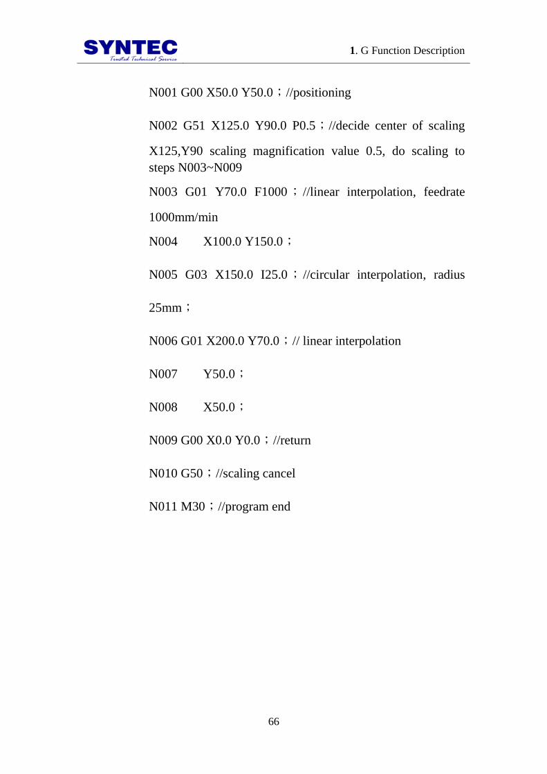
N001 G00 X50.0 Y50.0;//positioning
N002 G51 X125.0 Y90.0 P0.5;//decide center of scaling
X125,Y90 scaling magnification value 0.5, do scaling to
steps N003~N009
N003 G01 Y70.0 F1000; //linear interpolation, feedrate
1000mm/min
N004 X100.0 Y150.0;
N005 G03 X150.0 I25.0; //circular interpolation, radius
25mm;
N006 G01 X200.0 Y70.0;// linear interpolation
N007 Y50.0;
N008 X50.0;
N009 G00 X0.0 Y0.0;//return
N010 G50;//scaling cancel
N011 M30;//program end
1. G Function Description
67
1.2.23 G51.1/G50.1: PROGRAMMABLE
MIRROR IMAGE
Command form:
G51.1 X___Y___Z___;
G50.1;//programmable mirror image cancel
X, Y, Z: mirror point (axis) coordinate value.
Description:
when cut symmetry shape, we only need one program
between left side or right side, and use this function we can
process another side. G51.1 specify point(position) and axis of
symmetry for producing a mirror image
if there is only one axis specify mirror image on specified
plane, circular、tool length compensation or the direction of
coordinate rotation or direction of compensation, all of those
execute reverse.
because of this function use in part coordinates, when
counter reset or work coordinates change, center of mirror image
is changed.
G28, G30 in programmable mirror image, before the
mid-point , programmable mirror image is effective, after the
mid-point, programmable mirror image is not execute.
execute G29 in programmable mirror image, that is
effective to mirror image of mid-point.
Note:
Execute mirror image cancel out of the center point,
absolute value can not match with mechanical position, as the
below PIC (this status continues until executing G90、G28 or
G30). If you specify the center of mirror image again in the
absolute static status, it will be specified to a unable expect
position. Please use absolute positioning after mirror image
cancel.

1. G Function Description
68
Axis of symmery
Absolute value(specified position
by program)
Mechanical position
Use increment to move after canceling mirror image
Mirror image cancel
Specify the axis of symmery

1. G Function Description
69
Example 1:
Tool path that
map Y=55
Tool path that
map X=60 O
D (80,95)
C (120,105)
Y=55
symmery axis
Origin tool path
A (80,75) B (120,75)
(80,35) (120,35)
(80,15) (120,5)
(40,95)
(40,75) (10,75)
(10,105)
X=60
symmery axis
X
Y
X=60,Y=55
Program description:
N001 T1 S1000 M03;//use tool NO. 1, 1000rpm(CW)
N002 M98 H100;//execute sub-program
N003 G51.1 X60.0;//execute programmable mirror image
that symmery axis X=60
N004 M98 H100;// execute sub-program
N005 G50.1;//programmable mirror image cancel
N006 G51.1 Y55.0;//execute programmable mirror image
that symmery axis Y=55
N007 M98 H100;// execute sub-program
N008 G50.1;// programmable mirror image cancel
N009 M05;//spindle stops

1. G Function Description
70
N010 M30;//program ends
N100;//sub-program list
G00 X60.0 Y55.0;//positioning to specified point
G01 Y75.0;//linear interpolation to O point
X80.0;//OA
X120.0;//AB
Y105.0;//BC
X80.0 Y95.0;//CD
Y75.0;//DA
M99;//sub-program ends

1. G Function Description
71
Example 2: processing example
X
Y
Thickness 10mm
Program zero point
Original tool starting
point and
Y=0 tool starting
point after mirror
image
Original interpolation path
X=0 tool strating point after
mirror image
And X=0, Y=0 tool starting
point after mirror image
Program description: process a trough that flower shaped
N001 T1 S1000 M03 ; //tool No.1(diameter 10mm),
1000rpm(CW)
N002 G41 D01; //set cutter compensation left of tool
No.1(D01 = 5)
N003 M98 H100;//execute sub-program
N004 G51.1 X0.0;//execute programmable mirror image at
symmery axis X=0
N005 M98 H100;//execute sub-program
N006 G50.1;//programmable mirror image cancel
N007 G51.1 X0.0 Y0.0;// execute programmable mirror
image at symmery point X=0, Y=0
N008 M98 H100;// execute sub-program
N009 G50.1;// programmable mirror image cancel

1. G Function Description
72
N010 G51.1 Y0.0;// execute programmable mirror image at
symmery axis Y=0
N011 M98 H100;// execute sub-program
N012 G50.1;// programmable mirror image cancel
N013 G40;//cutter compensation cancel
N014 M05;//spindle stops
N015 M30;//program ends
Sub-program
N100;sub-program list
G00 X58.0 Y0.0 Z10.0;//positioning to the above of starting
position
G01 Z-10.0;//linear interpolation to bottom of workpiece
G03 X49.36 Y7.9744 R8.0;//circular interpolation(CCW),
radius 8mm
G03 X40.5415 Y29.2641 R50.0 ; // circular
interpolation(CCW), radius 50mm
G03 X29.2641 Y40.5415 R8.0 ; // circular
interpolation(CCW), radius 8mm
G03 X7.9744 Y49.36 R50.0;// circular interpolation(CCW),
radius 50mm
G03 X0.0 Y58.0 R8.0;// circular interpolation(CCW), radius
50mm

1. G Function Description
73
G00 Z10.0;//positioning to above of end point
M99 ;//sub-program end, continue to execute main program

1. G Function Description
74
1.2.24 G52: LOCAL COORDINATE SYSTEM
Command form:
G52 X__ Y__ Z__ ;
X、Y、Z: coordinate values
Description:
specify a work coordinate system(G54~G59), when
workpiece need to set another coordinate system, that coordinate
system is local coordinate system.
G52 X0.0 Y0.0 Z0.0: cancel the coordinate system
Coordinate system:
G56
G55 G54
G52
Local coordinate system
Program
coordinate
Work coordinate
Y
X Program zero
point

1. G Function Description
75
Example:
(100, 65)
(90,15) (110, 15)
10
20
20 10
10 20
20
10
G
52
G54
thickness10mm
X
Y
1st hole 2nd hole
3rd hole
Program description:
N001 T1 S1000 M03;//tool No.1(diameter 10mm), spindle
1000rpm (CW)
N002 G54 X0.0 Y0.0 Z0.0;//specify work coordinate (G54)
N003 G00 X90.0 Y15.0 Z10.0;//positioning to above of
specified position
N004 G43 H01;//tool length compensation (tool No.1)
N005 G99 G81 Z-15.0 R2.0 F1000;//execute drilling cycle,
stop at R point when return, feedrate 1000mm/min, drill 1st
hole
N006 X110.0;//drill 2nd
hole
N007 X100.0 Y65.0;//drill 3rd
hole
N008 G80;//cancel cycle
N009 M05;//spindle stops

1. G Function Description
76
N010 G28 X0.0 Y0.0 Z10.0; //reference point return,
X0.0,Y0.0,Z10.0 to be center point
N011 T2 M06 S1000 M03;//execute tool exchange(tool
No.2 diameter 10mm), after finishing, spindle start to turn,
1000rpm(CW)
N012 G52 X30.0 Y30.0 Z0.0;//specify local coordinate zero
point to the work coordinate (G54) of
X40.0,Y40.0,Z0.0(geometry center of workpiece)
N013 G00 X0.0 Y0.0 Z10.0;//positioning to local coordinate
X0.0,Y0.0,Z10.0(above the hole)
N014 G01 Z-12.0;//linear interpolation to bottom of the hole
N015 G17 G41 D02;//cutter compensation left (tool No.2)
N016 G91 X20.0;//specify to use increment to interpolation
N017 Y10.0;
N018 X-10.0;
N019 Y10.0;
N020 X-20.0;
N021 Y-10.0;
N022 X-10.0;
N023 Y-20.0;
N024 X10.0;
N025 Y-10.0;

1. G Function Description
77
N026 X20.0;
N027 Y10.0;
N028 X10.0;
N029 Y10.0;
N030 G90 G00 Z10.0;//specify to use absolute positioning
N031 G52 X0.0 Y0.0 Z0.0;//cancel local coordinate
N032 G40 M05;//cancel compensation, spindle stops
N033 M30;//program ends

1. G Function Description
78
1.2.25 G53: MACHINE COORDICATE
SYSTEM SELECTION
Command form:
G53 X___ Y___ Z___;
X: move to specify machine coordinate of X position.
Y: move to specify machine coordinate of Y position.
Z: move to specify machine coordinate of Z position.
Description:
Machine origin point is the fixed origin point when factory
build the CNC machine, this coordinate system is fixed;when
G53 is specified tool will move to the specified position on
machine coordinate, when tool returns to machine zero
point(0,0,0), this point is the origin point of machine coordinate
system.
<Notes>:
1. G53 only effective in specified block;
2. G53 only effective absolute mode(G90), not effective in
increment mode(G91);
3. before specify G53, must cancel related cutter
compensation ,tool length compensation or position
compensation;
4. before use G53 to set coordinate system, must set
coordinate system on the basement of reference return
position by manual.
Example:

1. G Function Description
79
N005
100
100
200
300
400
500
600
10
0
20
0
30
0
40
0
50
0
10
0
20
0
30
0
100 200 300 400 500 600 700
100 200 300 400 500
100 200 300 400
Basic coordinate system
G92
Machine coordinate system
G53
Workpiece coordinate system
G54
N003
N004
N002
3 Local coordinate system
G52
100
N001
Program description:
N001 G92 X-200.0 Y-100.0;//specify to basic coordinate
system
N002 G54 G90 X100.0 Y200.0;//to specified postion on
workpiece coordinate system
N003 G53 X300.0 Y100.0; //to specified position on
machine coordinate system
N004 X300.0 Y0;
//because of G53 only effective in one block, this block
continue G54 to the specified position on workpiece
coordinate system
N005 G52 X300.0 Y200.0; //set local coordinate to
specified position on workpiece coordinate system
N006 X0.0 Y0.0;

1. G Function Description
80
1.2.26 G54...G59.9: WORKPIECE
COORDICATE SELECTION
Command form:
_;__
9.59
2.59
1.59
59
58
57
56
55
54
ZYX
G
G
G
G
G
G
G
G
G
:
:
:
G54: 1st workpiece coordinate system
:
:
G59: 6th workpiece coordinate system
G59.1: 7th
workpiece coordinate system
:
:
G59.9: 15th workpiece coordinate system
X, Y, Z: move to specified position on setting workpiece
system;
Description:
In general when we operate numerical machine, if there are
many workpieces on the machine, we can use workpiece
coordinate system G54 to G59 six G codes G59.1~G59.9 to
present 15 different coordinate systems, it is convenient to
specify each workpiece position on machine coordinate, and it is
more convenient to our processed. Use parameter #3229 to

1. G Function Description
81
「disable workpiece coordinate system」(0: enable; 1: disable).
※G54……G59.9 settings:
“setting workpiece coordinate system” in operation
interface, setup G54 …G59.9 by each other. (consult ”milling
machine controller operation manual”)

1. G Function Description
82
Example:
G54
G58
G55
Program
coordinate
system
Y
X Program zero point
G56
G59 G57

1. G Function Description
83
1.2.27 G64: CUTTING MODE
Command form:
G61 ; // exact-stop examination mode
G62 ; // curved surface cutting mode
G63 ; // tapping mode
G64 ; // curved surface cutting mode
G64;
Description:
G64 is similar to G09, G61 in usage, NC use smooth cutting
face mode to cut. This mode does not decelerate and stop
between G61 and reverse cutting feed block, the mode will
continue to execute next block. G64 can be canceled by G61,
G62, G63.
Command
name G code range description
Exact stop G09 Only effective in
block with G09.
When tool decelerates at the end
of path, The precision error
occurs at the corner when the
tool direction turns. G09 is used
to control the precision error.
Exact stop G61
G61 is effective
until we set G62,
G63, G64.
G61 is similar to G09. The
difference is G61 effective until
we set G62, G63, or G64. Tool
decelerates at the end of corner.
When tool arrived at the
terminal, a feedback signal is
sent to ensure the position is in
the setting range. The next path
is executed after the feedback
control.
G62
G62 is effective
until we set G61,
G63, or G64.
Applicable to curved surface
cutting. Tool does not decelerate
at the end of path (refer to the
speed command curve shown
below) and continue execute next

1. G Function Description
84
path.
G63
G63 is effective
until we set G61,
G62, or G64.
Applicable to tapping. To
synchronize spindle and feed
axis. The relation between
spindle and feed axis is
determined by the ratio of
spindle rotate speed and feedrate.
During tapping, feed overrode
and feed hold cannot be adjusted.
Cutting
mode G64
G64 is effective
until we set
G61、G62、G63.
Tool does not decelerate on the
end of path, and continue to
execute next path after to
specified point.

1. G Function Description
85
1.2.28 G65: SIMPLE CALL
Command form:
G65 P L ;
P: number of the program to call;
L: repetition count;
Description:
After calling macro, P is called to execute and L__
indicates repeating times. But it is enable only in the block with
G65.
Example:
G65 P10 L20 X10.0 Y10.0
//Call sub-program O0010 continuously 20 times, and set
X=10.0 and Y=10.0 into sub-program.

1. G Function Description
86
1.2.29 G66/G67: MACRO CALL
Command form:
G66 P L ;macro call
G67 ;macro call cancel
P: number of the program to call;
L: repetition count;
Description:
After G66 is called, P is called to execute and L__
indicates repeating times. If there is a moving block, G66 block
will be executed again after moving block ends until using G67
to cancel it.
Example:
G91
G66 P10 L2 X10.0 Y10.0 //repeat twice calling sub-program
O0010 and set X=10.0 and Y=10.0 into sub-program.
X20.0 //Move to position X=20.0. After moving, call G66
P10 L2 X10.0 Y10.0.
Y20.0 //Move to position Y=20.0. After moving, call G66
P10 L2 X10.0 Y10.0.
G67 //Cancel macro call mode.

1. G Function Description
87
1.2.30 G68/G69: COORDINATE ROTATION
Command form:
(G17) G68 X_ Y_ R_; // start coordinate rotation
(G18) G68 Z_ X_ R_;
(G19) G68 Y_ Z_ R_;
G69; // Disable coordinate rotation
X_, Y_, Z_: absolute coordinate of center of rotation
R_: angle of rotation
Description
After coordinate rotation start, all movement command will
rotate with rotation center, so the geometric figure rotate a angle.
Rotation center only effective in absolute command, if all
command is increment, the actual rotation center is the starting
point of path.
Example 1:
G54 X0 Y0 F3000.;
G16; // start polar coordinates
G90 G00 X50. Y9.207 R8.; // positioning to
starting point
M98 H100; // first process
G68 X0 Y0 R90.; // coordinate rotates
90∘
M98 H100; // second process
G68 X0 Y0 R180.; // coordinate rotates
180∘
M98 H100; // third process
G68 X0 Y0 R270.; // coordinate rotates
270∘
M98 H100; // fourth process

1. G Function Description
88
G69; // coordinate rotation
cancel
G15; // polar coordinate cancel
M02; // main program end
N100 // orbit sub-program start
G90 G01 X50. Y9.207 R8.;
G03 X50. Y80.793. R50.;
G03 X50. Y99.207 R8.;
M99; // orbit sub-program return
stepping continue Enlarge and
reduce return cancel
Ready
Auto run alarm
Program edit
Absolute mode
Example 2:
G54 X0 Y0 F3000.;
G16; // start polar coordinate
G90 G00 X50. Y9.207 R8.; // positioning to
starting point
M98 H100; // first process
G68 X0 Y0 R45.; // coordinate rotates

1. G Function Description
89
45∘
M98 H100; // second process
G68 X0 Y0 R90.; // coordinate rotates
90∘
M98 H100; // thied process
G68 X0 Y0 R135.; // coordinate rotates
135∘
M98 H100; // fourth process
G68 X0 Y0 R180.; // coordinate rotates
180∘
M98 H100; // fifth process
G68 X0 Y0 R225.; // coordinate rotates
225∘
M98 H100; // sixth process
G68 X0 Y0 R270.; // coordinate rotates
270∘
M98 H100; // seventh process
G68 X0 Y0 R315.; // coordinate rotates
315∘
M98 H100; // eighth process
G69; // coordinate rotates cancel
G15; // polar coordinate cancel
G00 X-80. Y0.
M98 H200; // process first “flower”
G51.1 Y-40.; // symmetry axis
Y-40.
M98 H200; // process second “flower”
G50; // mirror image cancel
G90 G81 Z-20. R2. F1000. K0; // start G81 drilling
cycle
G134 X0 Y0 I75. J30. K6; // circumference hole

1. G Function Description
90
cycle
G137.1 X60. Y-60. I20. J-20. P3 K3; // chess type hole
cycle
G80; // drilling cycle cancel
M02; // main program end
N100 // orbit sub-program
G90 G01 X50. Y9.207;
G03 X50. Y35.793 R50.;
G03 X50. Y54.207 R8.;
M99; // sub-program return
N200 // sub-program start
(flower)
G90 G00 X-70. Y10.;
G91 G03 X-20. R10.;
G03 Y-20. R10.;
G03 X20. R10.;
G03 Y20. R10.;
M99; // sub-program
return(flower)

1. G Function Description
91
Auto run Ready
alarm
Absolute mode
Program edit
continue Enlarge and reduce
return cancel stepping

1. G Function Description
92
1.2.31 G70/G71: UNIT SETTING OF
INCH/METRIC SYSTEM
Command form:
G70;
G71;
Description:
G70: inch system
G71: metric system
After change inch/metric system, origin offset value of
workpiece coordinate, tool data, system parameter, and reference
point, all of that is still correct. System will deal the change of
unit automatically. After change inch/metric system, item below
will change as follow:
Coordinate, unit of speed
increment JOG unit
MPG JOG unit
Decimal Point Input
When parameter is inputted by decimal point input, will to
be the common measurement unit, mm, inch, sec…etc., if input
by whole number, it will to be the Min unit that system default,
m, ms…etc.
example:
decimal point: .
whole number:

1. G Function Description
93
1.2.32 Cycle perform function:
G
Code Cutting Bottom of the hole Escape Application
G73
Intermitte
nt cutting
feed
----
Speedy
movemen
t
High speed peck
drill cycle
G74 Cutting
feed
After stopping, spindle
rotate clockwise
Cutting
feed
Left hand taping
cycle
G76 Cutting
feed
Spindle location stop and
offset a displacement
value
Speedy
movemen
t
Fine boring cycle
G80 ---- ---- ---- Cycle cancel
G81 Cutting
feed ----
Speedy
movemen
t
Drilling cycle
G82 Cutting
feed Dwell
Speedy
movemen
t
Drilling cycle of
dwell on the hole
bottom
G83
Intermitte
nt cutting
feed
----
Speedy
movemen
t
Peck drill cycle
G84 Cutting
feed
Spindle reverse after
dwell
Cutting
feed
Tapping drilling
cycle
G85 Cutting
feed ----
Cutting
feed Drilling cycle
G86 Cutting
feed Spindle dwell
Speedy
movemen
t
Boring cycle
*G87 Cutting
feed Spindle rotate CW
Speedy
movemen
t
Fine boring cycle of
back side
*G88 Cutting
feed Spindle stop after dwell
Manual
movemen
t
Fine boring cycle of
half automation

1. G Function Description
94
G89 Cutting
feed Dwell
Cutting
feed
Boring cycle of
dwell on the hole
bottom
Fixed cycle address and meaning:
Address Address meaning
G Selection of fixed cycle
X Selection position of drilling point(increment or
absolute)
Y Selection position of drilling point(increment or
absolute)
Z Selection position of hole bottom(increment or absolute)
P Dwell time when hole is in the bottom
Q
Cutting value in G73、G83, or specified movement value
(increment) in G76、G87
R Selection of R position(absolute or increment)
F Selection of federate
K Specify fixed cycle times 0~999

1. G Function Description
95
G17, G18, and G19 can set axis of drilling, list as below:
G Code Plane Axis of drilling
G17 X-Y plane Z axis
G18 Z-X plane Y axis
G19 Y-Z plane X axis
Return to R point:
When tool perform to the bottom of the hole, the tool can
return to initial position or R point. And that is decided by
G98/G99, G98 is back to initial position, G99 is back to R point.
Number of repeats K:
If we want to perform many holes in the same distance, we
can specify number of repeats K, range of K 0~9999, but the
first hole need to use increment mode(G91) to specify, or it will
repeat drilling in the same place.
When K=0, drilling data will be set, X, Y movement
command cannot be executed in block, drilling cannot be execute
too.
Cancel cycle:
G80 or G code of 01 group(G00/G01/G02/G03…etc.) can
cancel cycle.
Increment (G91)/ absolute(G90) mode:
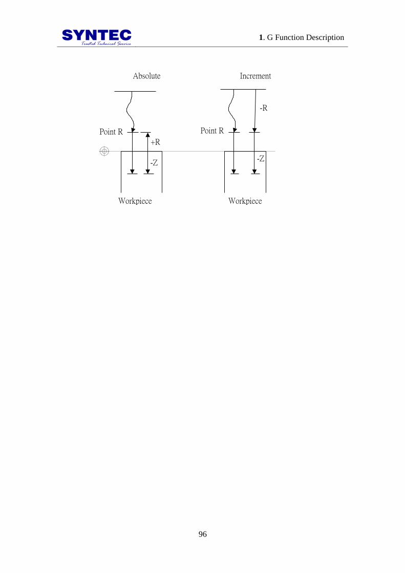
1. G Function Description
96
Workpiece Workpiece
+R
-Z
-R
-Z
IncrementAbsolute
Point R Point R

1. G Function Description
97
1.2.33 G73: HIGH SPEED PECK DRILL
CYCLE
Command form:
G73 X Y Z R Q F K ;
X or Y : hole position data (absolute/increment)
Z :
G91: the distance from the bottom of the hole to point Z
(directional)
G90: program position of point Z
R :
G91: the distance from initial level to R point level
(directional)
G90: program position of point R
Q : depth of cut for each cutting feed (increment and positive,
minus will be ignore)
F : feedrate
K : number of repeats (movement of repeats and action of
drilling, G91 increment effective)
X, Y, Z, R can use G90/G91 to decide absolute or increment
PIC:

1. G Function Description
98
Q
Q
Q
d
d
Z point
R point
Initial point
Dwell P(s)
Q
Q
Q
d
d
Z point
R point
Initial point
G98 G99
d:parameter setting
(X,Y) (X,Y)
d:parameter setting
Dwell P(s)
Description:
1. use G00 to move to specified (X,Y) when performance
start
2. use G00 to reach specified R point.
3. use G01 to interpolate a distance Q at the present depth
4. use G00 to return a distance d (CNC parameter 4002)
5. repeat drilling hole until reach the Z point
6. use G00 to return initial point(G98) or programmable R
point(G99)
Notes:
1. d distance is defined in CNC parameter No.4002.
2. before using G73, please use M Code let the drill start to
turn.
3. if M Code and G73 are specified in the same block ,this
M Code only executes in the first time of positioning in
that block, when K is used to specify numbers of times,
this M Code is executed for the first only, for the second
hole and subsequent holes, the M Code is not executed.

1. G Function Description
99
4. G73 is module G Code , when use G73 once ,it is
effectively always ,we only give the (X,Y) in the next
line of program ,then controller will start to drill of
(X,Y).
5. this module G code ,use G80 to cancel ,or
G00 ,G01,G02,G03 or other cycle this G code will be
canceled automatically.
Condition:
1. Before drilling axis be changed, Canned Cycle must be
canceled first.
2. If a Block is not included movement command of any
axes (X, Y, Z), then drilling can not be executed.
3. The data that Q and R specified, only be set in the block
we execute drilling, it can not be set in the block we do
not execute drilling.
4. G Code group 01 and G73 can not be specified in the
same block, or G73 Canned Cycle will be cancel.
5. In Canned Cycle, tool length compensation
(G41/G42/G40)will be ignored.
Program example:
F1000. S500;
M03; // start the drill to turn CW
G90;
G00 X0. Y0. Z10.; // positioning to initial point
G17;
G90 G99;
//set the R point, Z point and hole 1, cutting rate 2.0
G73 X5. Y5. Z-10. R-5. Q2.;
X15.; // hole 2
Y15.; // hole 3
G98 X5.; // hole 4, and return to initial point
X10. Y10. Z-20.; // hole 5, and set new Z point be -20
G80;
M05; // stop drill
M02;

1. G Function Description
100
1.2.34 G74: LEFT HAND TAPPING CYCLE
Command form:
G74 X Y Z R P F K ;
X_ or Y_: coordinates of holes (absolute/increment)
Z_:
G91: the distance from the bottom of the hole to point Z
(directional)
G90: program position of point Z
R_:
G91: the distance from initial level to R point level
(directional)
G90: program position of point R
P_: dwell time (s)
F_: feedrate
K_: number of repeats (repeat movement and drilling, G91 is
effective)
X, Y, Z, R: use G90/91 to decide absolute or increment
PIC:
Z point
R point
Initial point
G98
Z point
R point
Initial point
Rotate CW after dwell P(s)
G99
Rotate reverse after dwell P(s)
(X,Y) (X,Y)
Rotate reverse after dwell P(s)
Rotate CW after dwell P(s)
Description:
1. use G00 to move to specified(X,Y) when start to
perform
2. use G00 to specified point R.
3. use G01 to reach the bottom of the hole ,point Z

1. G Function Description
101
4. dwell P(s) then reverse the drill
5. use G01 raise to point R
6. dwell P(s) then reverse the drill
7. use G00 to raise to initial point (G98) or programmable
point R(G99)
tapping pitch / feed rate reduce:
G94: F (mm/min) =S (RPM) * P (mm/rev)
G95: F (mm/rev) = P (mm/rev)
G74: when performing, feedrate(F), spindle RPM(S),
they are not controlled by turning switch(fixed at 100%)

1. G Function Description
102
Notes:
1. before G74, use M Code let drill start to rotate CCW
2. if M Code and G74 are specified in the same block ,this
M Code only executes in the first time of positioning in
that block
3. when K is used to specify numbers of times, this M
Code is executed for the first only, for the second hole
and subsequent holes, the M Code is not executed. G74
is module G Code ,it is always effective when we use
once ,we only specify (X,Y) in next line of
program ,controller will execute drilling at (X,Y)
4. this module G code ,use G80 to cancel ,when program
run into G00 , G01, G02 , G03 or other cycle ,this
module G code will be canceled automatically,
5. because there is a little time when spindle CW to CCW
in tapping ,please use P add dwell in G code
Condition:
1. before drilling axis be changed, Canned Cycle must be
canceled first.
2. if the Block does not include movement command of
any axes (X, Y, Z), then drilling will not be executed.
3. data that R specified only be set in blocks of executing
drilling, it can not be set in blocks of no executing
drilling.
4. G code 01 group and G74 can be specified in the same
block, or G74 Canned Cycle will be canceled.
5. in Canned Cycle, tool length
compensation(G41/G42/G40) will be ignored.
Program example:
F1000. S500;
G90;
G00 X0. Y0. Z10.; // positioning to initial point
G17;
M04; // start drill to rotate CCW
1. G Function Description
103
G90 G99;
//specify point R、point Z and hole 1 coordinate values, dwell
2 s
G74 X5. Y5. Z-10. R-5. P2.;
X15.; // hole 2
Y15.; // hole 3
G98 X5.; // hole 4, and set to return to initial point
X10. Y10. Z-20.; // hole 5, and set new point Z to be -20.
G80;
M05; // drill stops
M02;

1. G Function Description
104
1.2.35 G76: FINE BORING CYCLE
Command form:
G76 X Y Z R Q P F K ;
X_ or Y_: hole position data (absolute/increment position)
Z_:
G91: the distance from the bottom of the hole to point Z
(directional)
G90: program position of point Z
R_:
G91: the distance from initial level to R point level
(directional)
G90: program position of point R
Q_: shift amount at the bottom of the hole (positive, negative
will be ignored)
P_: dwell time at the bottom of the hole (s)
F_: feedrate
K_: number of repeats (repeat moving and drilling ,G91 is
effective)
X, Y, Z, R is absolute or increment mode, decided by
G90/G91
PIC:
Z point
R point
Initial point
G98
Z point
R point
Initial point
G99
Dwell P(s)
OSS OSS
q q
Drill Start
(X,Y) (X,Y)
Dwell P(s)
Drill Start

1. G Function Description
105
Tool
offset q OSS
(Oriented Spindle Stop)
Oriented Spindle Stop(OSS)
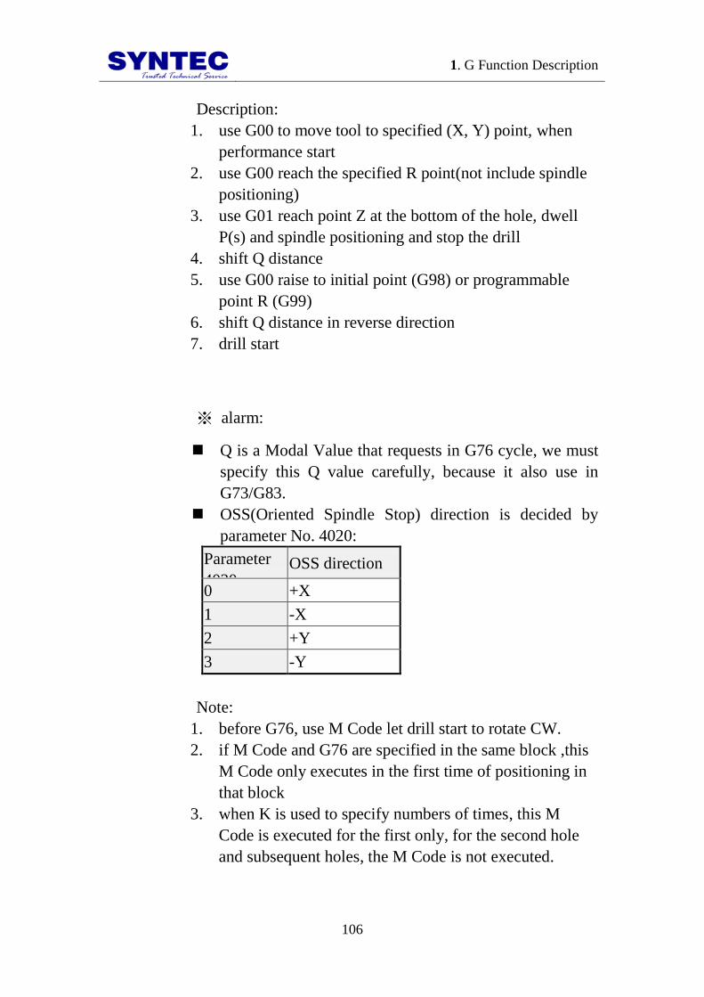
1. G Function Description
106
Description:
1. use G00 to move tool to specified (X, Y) point, when
performance start
2. use G00 reach the specified R point(not include spindle
positioning)
3. use G01 reach point Z at the bottom of the hole, dwell
P(s) and spindle positioning and stop the drill
4. shift Q distance
5. use G00 raise to initial point (G98) or programmable
point R (G99)
6. shift Q distance in reverse direction
7. drill start
※ alarm:
Q is a Modal Value that requests in G76 cycle, we must
specify this Q value carefully, because it also use in
G73/G83.
OSS(Oriented Spindle Stop) direction is decided by
parameter No. 4020:
Parameter
4020 OSS direction
0 +X
1 -X
2 +Y
3 -Y
Note:
1. before G76, use M Code let drill start to rotate CW.
2. if M Code and G76 are specified in the same block ,this
M Code only executes in the first time of positioning in
that block
3. when K is used to specify numbers of times, this M
Code is executed for the first only, for the second hole
and subsequent holes, the M Code is not executed.

1. G Function Description
107
4. G76 is module G Code ,it is always effective when we
use once ,we only specify (X,Y) in next line of
program ,controller will execute drilling at (X,Y)
5. this module G code ,use G80 to cancel ,when program
run into G00, G01, G02 , G03 or other cycle ,this
module G code will be canceled automatically.

1. G Function Description
108
Condition:
1. before drilling axis be changed, Canned Cycle must be
canceled first.
2. if the Block does not include movement command of
any axes (X, Y, Z), then drilling will not be executed.
3. Q must be specified a positive value. If Q is negative
value ,it will be thought to be a positive value (absolute
value), data that Q and R specified only be set in drilling
blocks, it will not be set in not drilling blocks.
4. G Code group 01 and G76 can not be specified in the
same block, or G76 Canned Cycle cancel.
5. in Canned Cycle, tool length compensation
(G41/G42/G40)will be ignore.
Program example:
F1000. S500;
M03; // start drill rotate CW
G90;
G00 X0. Y0. Z10.; // position to initial point
G17;
G90 G99;
//specify point R、point Z and hole 1, shift amount at bottom
of hole2.0, dwell time 5 s
G76 X5. Y5. Z-10. R-5. Q2. P5.;
X15.; // hole 2
Y15.; // hole 3
G98 X5.; // hole 4, and return to initial point
X10. Y10. Z-20.; // hole 5, and specify the new point Z to be
-20.0
G80;
M05; // drill stops
M02;

1. G Function Description
109
1.2.36 G81: DRILLING CYCLE
Command form:
G81 X Y Z R F K ;
X_ or Y_: hole position data (absolute/increment position)
Z_:
G91: the distance from the bottom of the hole to point Z
(directional)
G90: program position of point Z
R_:
G91: the distance from initial level to R point level
(directional)
G90: program position of point R
F_: feed rate
K_: number of repeats (repeat moving and drilling, G91 is
effective)
X, Y, Z, R is absolute or increment mode, decided by
G90/G91
PIC:
Z point
R point
Initial point
Dwell P(s)
G98
Z point
R point
Initial point
G99
(X,Y) (X,Y)
Dwell P(s)
Description:
1. use G00 to positioning to specified (X,Y) when start to
perform
2. use G00 to reach specified point R.

1. G Function Description
110
3. use G01 to reach point Z the bottom of the hole
4. use G00 to raise to initial point(G98) or program point
R(G99)

1. G Function Description
111
Note:
1. before G81, use M Code to let drill start to rotate.
2. if M Code and G81 are specified in the same block ,this
M Code only executes in the first time of positioning in
that block,
3. when K is used to specify numbers of times, this M
Code is executed for the first only, for the second hole
and subsequent holes, the M Code is not executed.
Condition:
1. before drilling axis be changed, Canned Cycle must be
canceled first.
2. if the Block does not include movement command of
any axes (X, Y, Z), then drilling will not be executed.
3. data R specified only be set in drilling block, it will not
be set in not drilling block.
4. G Code group 01 and G81 can not be specified in the
same block, or G76 Canned Cycle cancel.
5. in Canned Cycle, tool length compensation
(G41/G42/G40)will be ignore.
Program example:
F1000. S500;
G90;
G00 X0. Y0. Z10.; // positioning to initial point
G17;
G90 G99; //setting point R、point Z and hole 1
G81 X5. Y5. Z-10. R-5.;
X15.; // hole 2
Y15.; // hole 3
G98 X5.; // hole 4, and return to initial point
X10. Y10. Z-20.; // hole 5, and set new point Z to be -20
G80;
M02;

1. G Function Description
112
1.2.37 G82: DRILLING CYCLE OF DWELL
ON THE HOLE BOTTOM
Command form:
G82 X Y Z R P F K ;
X_ or Y_: hole position data (absolute/increment mode)
Z _:
G91: the distance from the bottom of the hole to point Z
(directional)
G90: program position of point Z
R_:
G91: the distance from initial level to R point level
(directional)
G90: program position of point R
P_: dwell time at the bottom of the hole (s)
F_: feed rate
K_: number of repeats (repeat moving and drilling, G91 is
effective)
X, Y, Z, R is absolute or increment mode, decided by
G90/G91
PIC:
Z point
R point
Initial point
Dwell P(s)
G98
Z point
R point
Initial point
Dwell P(s)
G99
(X,Y) (X,Y)
Description:
1. use G00 to positioning to specified (X,Y) when start to
perform

1. G Function Description
113
2. use G00 to reach specified point R.
3. use G01 to reach point Z the bottom of the hole
4. dwell P (s)
5. use G00 raise to initial point(G98) or program point
R(G99)
Notes:
1. before G82, use M Code to let drill start to rotate.
2. if M Code and G82 are specified in the same block ,this
M Code only executes in the first time of positioning in
that block
3. when K is used to specify numbers of times, this M
Code is executed for the first only, for the second hole
and subsequent holes, the M Code is not executed
1. G Function Description
114
Condition:
1. before drilling axis changes, Canned Cycle must be
canceled first.
2. if the Block does not include movement command of
any axes (X, Y, Z), then drilling will not be executed.
3. data R specified only be set in drilling block, it will not
be set in not drilling block.
4. G Code group 01 and G82 can not be specified in the
same block, or G76 Canned Cycle cancel.
5. in Canned Cycle, tool length compensation
mode(G41/G42/G40) will be ignored.
Program example:
F1000. S500;
G90;
G00 X0. Y0. Z10.; // positioning to initial point
G17;
M03; // start drill to rotate CW
G90 G99;
//specified point R、point Z and hole 1, dwell time 2 s
G82 X5. Y5. Z-10. R-5. P2.;
X15.; // hole2
Y15.; // hole3
G98 X5.; // hole4, and return to initial point
G80;
M05; // drill stops
M02;

1. G Function Description
115
1.2.38 G83: PECK DRILL CYCLE
Command form:
G83 X Y Z R Q F K ;
X_ or Y_: hole position data (absolute/increment mode)
Z_:
G91: the distance from the bottom of the hole to point Z
(directional)
G90: program position of point Z
R_:
G91: the distance from initial level to R point level
(directional)
G90: program position of point R
Q_: the feed depth (increment and positive value; negative
value is neglected)
P_: dwell time at the bottom of the hole(s)
F_: feed rate
K_: number of repeats (repeat moving and drilling, G91 is
effective)
X, Y, Z, R is absolute or increment mode, decided by
G90/G91
PIC:
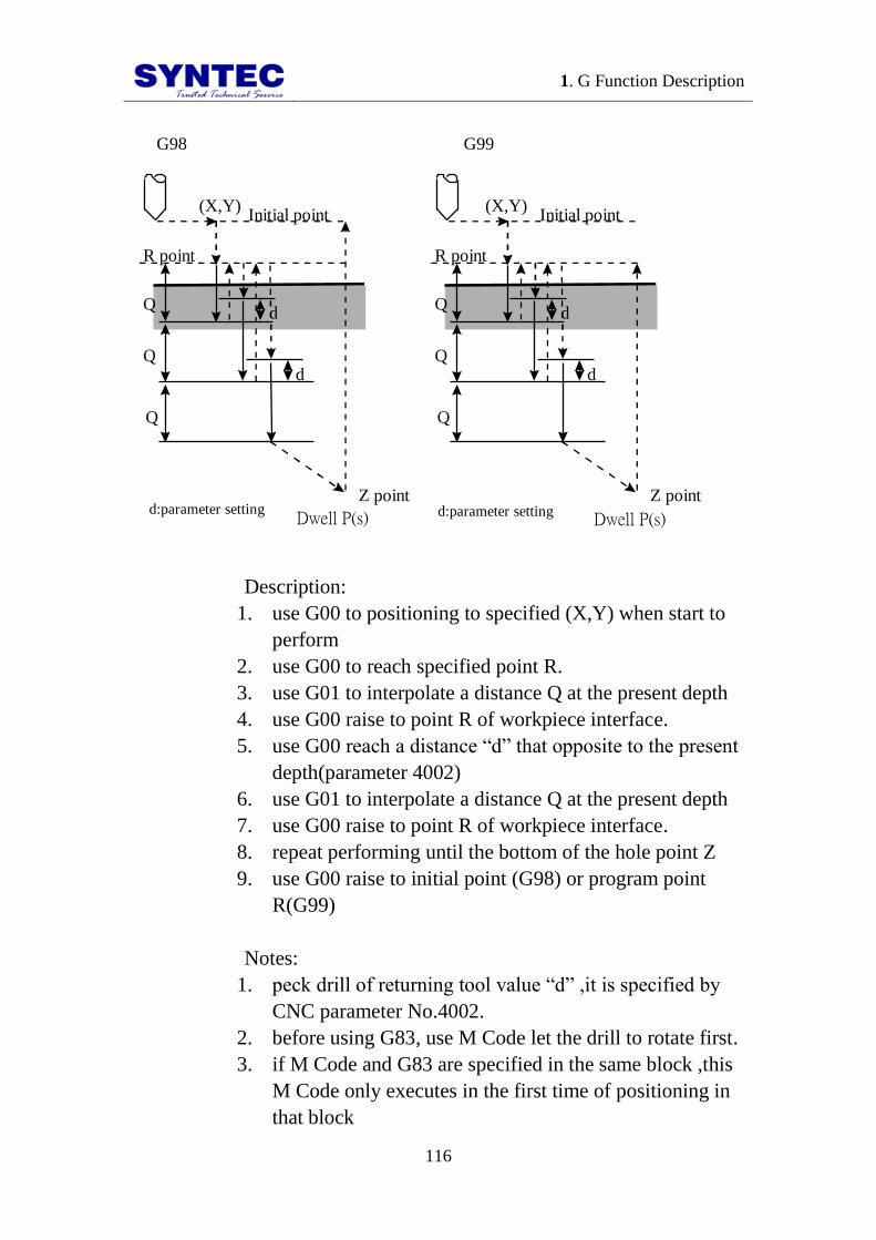
1. G Function Description
116
Q
Q
Q
d
d
Z point
R point
Initial point
Dwell P(s)
G98
Q
Q
Q
d
d
Z point
R point
Initial point
G99
(X,Y) (X,Y)
d:parameter setting d:parameter setting Dwell P(s)
Description:
1. use G00 to positioning to specified (X,Y) when start to
perform
2. use G00 to reach specified point R.
3. use G01 to interpolate a distance Q at the present depth
4. use G00 raise to point R of workpiece interface.
5. use G00 reach a distance “d” that opposite to the present
depth(parameter 4002)
6. use G01 to interpolate a distance Q at the present depth
7. use G00 raise to point R of workpiece interface.
8. repeat performing until the bottom of the hole point Z
9. use G00 raise to initial point (G98) or program point
R(G99)
Notes:
1. peck drill of returning tool value “d” ,it is specified by
CNC parameter No.4002.
2. before using G83, use M Code let the drill to rotate first.
3. if M Code and G83 are specified in the same block ,this
M Code only executes in the first time of positioning in
that block

1. G Function Description
117
4. when K is used to specify numbers of times, this M
Code is executed for the first only, for the second hole
and subsequent holes, the M Code is not executed.
Condition:
1. before drilling axis changes, Canned Cycle must be
canceled first.
2. if the Block does not include movement command of
any axes (X, Y, Z), then drilling will not be executed
3. data Q and data R specified only be set in drilling block,
it will not be set in not drilling block.
4. G Code group 01 and G83 can not be specified in the
same block, or G76 Canned Cycle cancel.
5. in Canned Cycle, tool length compensation mode
(G41/G42/G40) will be ignored.
Program example:
F1000. S500;
M03; // start drill to rotate CW
G90;
G00 X0. Y0. Z10.; // positioning to initial point
G17;
G90 G99; // specify point R, point Z and hole 1, cutting
federate 3.0
G83 X5. Y5. Z-10. R-5. Q3.;
X15.; // hole2
Y15.; // hole3
G98 X5.; // hole4, and return to initial point
G80;
M05; // drill stops
M02;

1. G Function Description
118
1.2.39 G84: TAPPING DRILLING CYCLE
Command form:
G84 X Y Z R P Q F K ;
X_ or Y_: hole position data (absolute/increment mode)
Z_:
G91: the distance from the bottom of the hole to point Z
(directional)
G90: program position of point Z
R_:
G91: the distance from initial level to R point level
(directional)
G90: program position of point R
P_: dwell time at the bottom of the hole(s)
Q_: the feed depth (increment and positive value; negative
value is neglected)
F_: feed rate
K_: number of repeats (repeat moving and drilling, G91 is
effective)
X, Y, Z, R is absolute or increment mode, decided by
G90/G91.
PIC:
Type I: None argument Q
Z point
R point
Initial point
Reverse after dwell P(s)
G98
Z point
R point
Initial point
G99
Rotate “+” direction after dwell P(s)
(X,Y) (X,Y)
Rotate “+” direction after dwell P(s)
Reverse after dwell P(s)
Description:

1. G Function Description
119
1. use G00 to positioning to specified (X,Y) when start to
perform
2. use G00 to reach specified point R
3. use G01 to reach point Z the bottom of the hole
4. dwell P(s) and reverse the drill
5. use G01 to raise to point R
6. dwell P(s) and reverse the drill
7. use G00 to raise to initial point(G98) or program point
R(G99)

1. G Function Description
120
TYPEⅡ: High Speed Peck Tapping (Custom Parameter
No.4001= 1)
Q
Q
Q
d
d
Point Z
Point R
Initial point
Reverse after dwell P(s)
G98
Q
Q
Q
d
d
Point Z
Point R
Initial point
G99
(X,Y) (X,Y)
d: parameter setting d: parameter setting
參數設定 Reverse after dwell P(s)
Description:
1. use G00 to positioning to specified (X,Y) when start to
perform
2. use G00 to reach specified point R
3. use G01 to interpolate a distance Q at the present depth
4. After dwell P(s), use G01 to reach a distance “d” that
opposite to the present depth (set by parameter 4002).
5. After dwell P(s), use G01 to interpolate a distance Q at
the present depth.
6. After dwell P(s), use G01 to reach a distance “d” that
opposite to the present depth (set by parameter 4002).
7. Repeat the above action until reaching the bottom of the
hole, point Z.
8. Dwell P(s) and reverse the tap. Then use G01 to rise to
point R (G99).
9. Dwell P(s) and reverse the tap. Then G00 to rise to
initial point (G98).

1. G Function Description
121

1. G Function Description
122
TYPEⅢ: General Peck Tapping (Custom Parameter
No.4001= 0)
Description:
1. Use G00 to positioning to specified (X, Y) when start to
perform.
2. Use G00 to reach specified point R.
3. Use G01 to interpolate a distance Q at the present depth.
4. Dwell P(s) and reverse the tap. Then use G01 to reach
point R.
5. Dwell P(s) and reverse the tap. Then use G01 to
interpolate a distance “Q” relative to the depth of present
hole.
6. Dwell P(s) and reverse the tap. Then use G01 to reach
point R.
7. Repeat the above action until reaching the bottom of the
hole, point Z.
8. Dwell P(s) and reverse the tap. Then use G01 to rise to
point R (G99).
9. Dwell P(s) and reverse the tap. Then use G00 to rise to
initial point (G98).
tapping pitch/perform speed, reduce :

1. G Function Description
123
G94: perform speed(F mm/min) =spindle rotate rate(S
RPM) * pitch(P mm/rev)
G95: perform speed(F mm/rev) = pitch(P mm/rev)
G84: when performing, perform speed(F) spindle rotate
rate(S), they are not controlled by turning switch(fix
100%)

1. G Function Description
124
Notes:
1. before using G84, use M Code to let the drill rotate
CCW
2. if M Code and G84 are specified in the same block ,this
M Code only executes in the first time of positioning in
that block
3. when the K is used to specify numbers of repeats, this M
Code is executed in the first hole only. G84 is module G
Code ,it is always effective when we use once ,we only
specify (X,Y) in next line of program ,controller will
execute drilling at (X,Y)
4. this module G Code ,will be canceled when G80
command ,or we command G00 ,G01,G02,G03 or other
cycle G code ,this module G code will be canceled
automatically
5. because there is a period of time that spindle from CW
to CCW at tapping , please command P to dwell a period
of time
Condition:
1. before drilling axis changes, Canned Cycle must be
canceled first.
2. if the Block does not include movement command of
any axes (X, Y, Z), then drilling will not be executed.
3. data R specified only be set in drilling block, it will not
be set in not drilling block.
4. G Code group 01 and G84 can not be specified in the
same block, or G76 Canned Cycle cancel.
5. in Canned Cycle, tool length compensation mode
(G41/G42/G40) will be ignored.
Program example:
F1000. S500;
G90;
G00 X0. Y0. Z10.; // positioning to initial point
G17;
M03; // start drill to rotate CW
G90 G99;

1. G Function Description
125
//specify point R、point Z and hole1
G84 X5. Y5. Z-10. R-5.;
X15.; // hole2
Y15.; // hole3
G98 X5.; // hole4, and return to initial point
G80;
M05; // drill stops
M02;
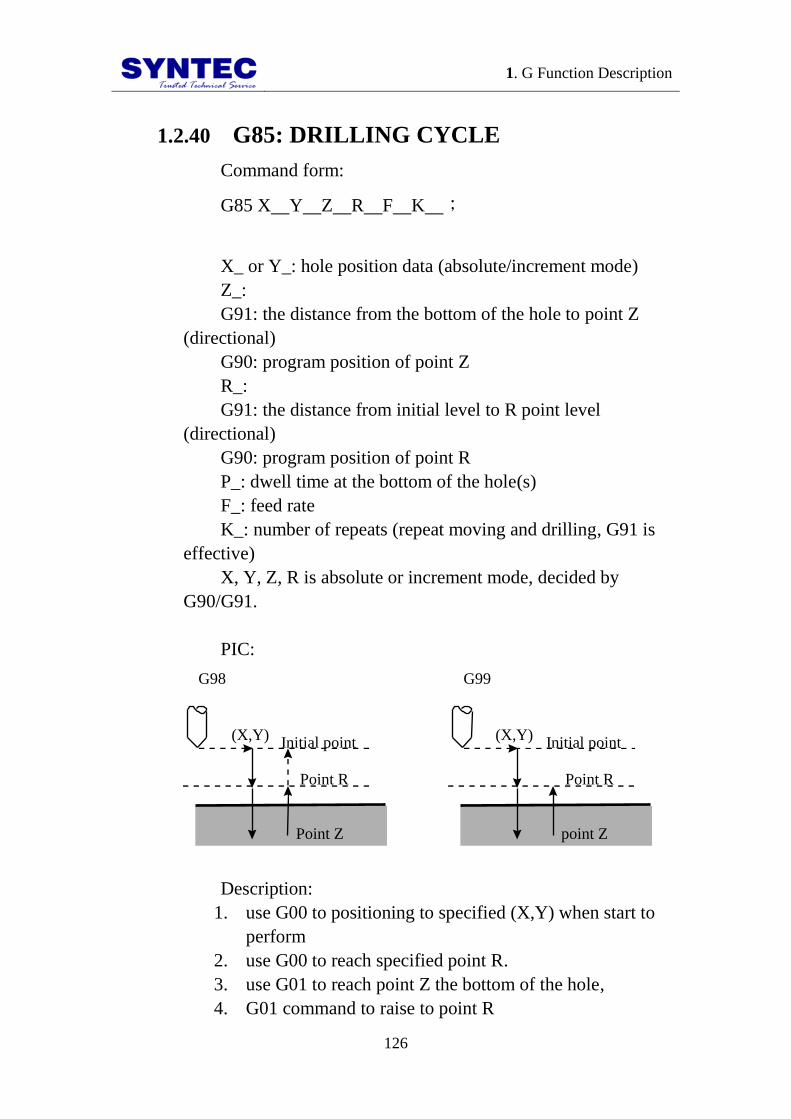
1. G Function Description
126
1.2.40 G85: DRILLING CYCLE
Command form:
G85 X Y Z R F K ;
X_ or Y_: hole position data (absolute/increment mode)
Z_:
G91: the distance from the bottom of the hole to point Z
(directional)
G90: program position of point Z
R_:
G91: the distance from initial level to R point level
(directional)
G90: program position of point R
P_: dwell time at the bottom of the hole(s)
F_: feed rate
K_: number of repeats (repeat moving and drilling, G91 is
effective)
X, Y, Z, R is absolute or increment mode, decided by
G90/G91.
PIC:
Point Z
Point R
Initial point
G98
point Z
Point R
Initial point
G99
(X,Y) (X,Y)
Description:
1. use G00 to positioning to specified (X,Y) when start to
perform
2. use G00 to reach specified point R.
3. use G01 to reach point Z the bottom of the hole,
4. G01 command to raise to point R

1. G Function Description
127
5. G00 command to raise to initial point(G98) or program
point R(G99)
Notes:
1. before G85 command, use M Code to let the spindle
rotate.
2. if M Code and G85 are specified in the same block ,this
M Code only executes in the first time of positioning in
that block.
3. when K is used to specify numbers of times, this M
Code is executed for the first only, for the second hole
and subsequent holes, the M Code is not executed.

1. G Function Description
128
Condition:
1. before drilling axis changes, Canned Cycle must be
canceled first.
2. if the Block does not include movement command of
any axes (X, Y, Z), then drilling will not be executed.
3. data R specified only be set in drilling block, it will not
be set in not drilling block.
4. G Code group 01 and G85 can not be specified in the
same block, or G76 Canned Cycle cancel.
5. in Canned Cycle, tool length compensation mode
(G41/G42/G40) will be ignored.
Program example:
F1000. S500;
G90;
G00 X0. Y0. Z10.; // positioning to initial point
G17;
M03; // start drill to rotate CW
G90 G99;
//specify point R、point Z and hole 1
G85 X5. Y5. Z-10. R-5.;
X15.; // hole2
Y15.; // hole3
G98 X5.; // hole4, and return to initial point
G80;
M05; // drill stops
M02;

1. G Function Description
129
1.2.41 G86: HIGH SPEED DRILLING CYCLE
Command form:
G86 X Y Z R F K ;
X or Y : hole position data (absolute/increment mode)
Z :
G91: the distance from the bottom of the hole to point Z
(directional)
G90: program position of point Z
R :
G91: the distance from initial level to R point level
(directional)
G90: program position of point R
P : dwell time at the bottom of the hole (s)
F : feed rate
K : number of repeats (repeat moving and drilling, G91 is
effective)
X, Y, Z, R is absolute or increment mode, decided by
G90/G91
PIC:
Point Z
Point R
Initial point
G98
Point Z
Point R
G99
Drill stops
Drill start to rotate
(X,Y) (X,Y) Initial point
Drill stops
Drill start to rotate
Description:
1. use G00 to positioning to specified (X,Y) when start to
perform
2. use G00 to reach specified point R.
3. use G01 to reach point Z the bottom of the hole,
1. G Function Description
130
4. use G00 to raise to initial point (G98) or program point
R(G99)
Notes:
1. before using G86, use M Code to let the drill to rotate.
2. if M Code and G86 are specified in the same block ,this
M Code only executes in the first time of positioning in
that block
3. when K is used to specify numbers of times, this M
Code is executed for the first only, for the second hole
and subsequent holes, the M Code is not executed.

1. G Function Description
131
Condition:
1. before drilling axis changes, Canned Cycle must be
canceled first.
2. if the Block does not include movement command of
any axes (X, Y, Z), then drilling will not be executed.
3. data R specified only be set in drilling block, it will not
be set in not drilling block.
4. G Code group 01 and G86 can not be specified in the
same block, or G76 Canned Cycle cancel.
5. in Canned Cycle, tool length compensation mode
(G41/G42/G40) will be ignored.
Program example:
F1000. S500;
G90;
G00 X0. Y0. Z10.; // positioning to initial point
G17;
M03; // start drill to rotate CW
G90 G99;
//specify point R、point Z and hole 1
G86 X5. Y5. Z-10. R-5.;
X15.; // hole2
Y15.; // hole3
G98 X5.; // hole4, and return to initial point
G80;
M05; // drill stops
M02;

1. G Function Description
132
1.2.42 G87: FINE BORING CYCLE OF BACK
SIDE
Command form:
G87 X Y Z R Q P F K ;
X_ or Y_: hole position data (absolute/increment position)
Z_:
G91: the distance from the bottom of the hole to point Z
(directional)
G90: program position of point Z
R_:
G91: the distance from initial level to R point level
(directional)
G90: program position of point R
Q_: shift amount at the bottom of the hole (positive, negative
will be ignored)
P_: dwell time at the bottom of the hole (s)
F_: feedrate
K_: number of repeats (repeat moving and drilling, G91 is
effective)
X, Y, Z, R is absolute or increment mode, decided by
G90/G91
PIC:

1. G Function Description
133
Z point
R point
Initial point
G98, G99
Dwell P(s) OSS
q
Drill Start
OSS
Drill Start
Tool
Offset q OSS
(Oriented Spindle Stop)
Oriented Spindle Stop(OSS) PIC

1. G Function Description
134
Description:
1. use G00 to positioning to specified (X,Y) when start to
perform
2. after OSS stops ,use the direction that parameter 4020
specify ,and shift amount a Q distance in reverse
direction
3. use G00 to reach specified point R, shift amount a Q
distance,
4. drill rotate CW.
5. G01 command to raise to point Z
6. after dwell P(s) and shift amount a Q distance in reverse
direction
7. G00 command to raise to initial point
8. after drill start and shift amount a Q distance.
※Alarm:
Q is a Modal Value that request in G87 cycle. This Q
value must be specified carefully because it is also used
in G73/G83 cycle.
OSS(Oriented Spindle Stop) direction is decided by
parameter No. 4020:
Parameter
4020 OSS direction
0 +X
1 -X
2 +Y
3 -Y
4 +Z
5 -Z
Notes:
1. before G87 command, use M Code to let the spindle
rotate.
2. if M Code and G87 are specified in the same block , this
M Code only executes in the first time of positioning in
that block
1. G Function Description
135
3. when K is used to specify numbers of times, this M
Code is executed for the first only, for the second hole
and subsequent holes, the M Code is not executed.
Condition:
1. before drilling axis changes, Canned Cycle must be
canceled first.
2. if the Block does not include movement command of
any axes (X, Y, Z), then drilling will not be executed.
3. Q must be specified to a positive value. If Q were a
negative value, it will be specified to positive value
(absolute value), data Q and data R specified only be set
in drilling block, it will not be set in not drilling block.
4. G Code group 01 and G87 can not be specified in the
same block, or G76 Canned Cycle cancel.
5. in Canned Cycle, tool length compensation mode
(G41/G42/G40) will be ignored.

1. G Function Description
136
Program example:
F1000. S500;
G90;
G00 X0. Y0. Z10.; // positioning to initial point
G17;
G90 G99;
M03; // start drill to rotate CW
//specify point R、point Z and hole 1, shift amount 5.0, dwell
time 4.0s
G87 X5. Y5. Z10. R-30. Q5. P4.;
X15.; // hole2
Y15.; // hole3
G80;
M05; // drill stops
M02;

1. G Function Description
137
1.2.43 G88: FINE BORING CYCLE OF HALF
AUTOMATION
Command form:
G88 X Y Z R P F K ;
X_ or Y_: hole position data (absolute/increment position)
Z_:
G91: the distance from the bottom of the hole to point Z
(directional)
G90: program position of point Z
R_:
G91: the distance from initial level to R point level
(directional)
G90: program position of point R
P_: dwell time at the bottom of the hole (s)
F_: feedrate
K_: number of repeats (repeat moving and drilling, G91 is
effective)
X, Y, Z, R is absolute or increment mode, decided by
G90/G91
PIC:
Point Z
Point R
Initial point
G98
Point Z
Initial point
G99
Drill stops after dwell P(s)
Drill Start
Drill Start
(X,Y) (X,Y)
Drill stops after dwell P(s)
Point R
※ for positioning by manual.
1. G Function Description
138
Description:
1. use G00 to positioning to specified (X,Y) when start to
perform
2. use G00 to reach specified point R.
3. use G01 to reach point Z the bottom of the hole,
4. drill stops after dwell P(s),
5. make the tool out of workpiece in manual mode and
reset
6. use G01 to move to point R
7. use G00 to raise to initial point(G98) or program point
R(G99)
8. drill rotate CW.
1. G Function Description
139
Notes:
1. before G88 command, use M Code to let drill start to
rotate first.
2. if M Code and G88 specify in the same block ,this M
Code only executes once when the first time positioning
in that block
3. when K is used to specify numbers of times, this M
Code is executed for the first only, for the second hole
and subsequent holes, the M Code is not executed.
Condition:
1. before drilling axis changes, Canned Cycle must be
canceled first.
2. if the Block does not include movement command of
any axes (X, Y, Z), then drilling will not be executed.
3. data R specified only be set in drilling block, it will not
be set in not drilling block.
4. G Code group 01 and G88 can not be specified in the
same block, or G76 Canned Cycle cancel.
5. in Canned Cycle, tool length compensation mode
(G41/G42/G40) will be ignored.
Program example:
F1000. S500;
G90;
G00 X0. Y0. Z10.; // positioning to initial point
G17;
M03; // start drill to rotate CW
G90 G99;
//specify point R、point Z and hole1, dwell 2.0s
G88 X5. Y5. Z-10. R-5. P3.;
X15.; // hole2
Y15.; // hole3
G98 X5.; // hole4, and return to initial point
G80;
M05; // drill stops
M02;

1. G Function Description
140
1.2.44 G89: BORING CYCLE OF DWELL ON
THE HOLE BOTTOM
Command form:
G89 X Y Z R P F K ;
X_ or Y_: hole position data (absolute/increment position)
Z_:
G91: the distance from the bottom of the hole to point Z
(directional)
G90: program position of point Z
R_:
G91: the distance from initial level to R point level
(directional)
G90: program position of point R
P_: dwell time at the bottom of the hole (s)
F_: feedrate
K_: number of repeats (repeat moving and drilling, G91 is
effective)
X, Y, Z, R is absolute or increment mode, decided by
G90/G91.
PIC:
pointZ
Point R
Initial point
G98
Point Z
Point R
Initial point
G99
Dwell P(s)
(X,Y) (X,Y)
Dwell P(s)
Description:
1. use G00 to positioning to specified (X,Y) when start to
perform

1. G Function Description
141
2. use G00 to reach specified point R.
3. use G01 to reach point Z the bottom of the hole
4. dwell P (s)
5. use G01 to raise to point R
6. use G00 to raise to initial point (G98) or program point
R(G99)
Notes:
1. before G89 command, use M Code to let the drill start to
rotate.
2. if M Code and G89 are specified in the same block ,this
M Code only executes in the first time of positioning in
that block
3. when K is used to specify numbers of times, this M
Code is executed for the first only, for the second hole
and subsequent holes, the M Code is not executed.

1. G Function Description
142
Condition:
1. before drilling axis changes, Canned Cycle must be
canceled first.
2. if the Block does not include movement command of
any axes (X, Y, Z), then drilling will not be executed.
3. data R specified only be set in drilling block, it will not
be set in not drilling block.
4. G Code group 01 and G89 can not be specified in the
same block, or G76 Canned Cycle cancel.
5. in Canned Cycle, tool length compensation mode
(G41/G42/G40)will be ignored.
Program example:
F1000. S500;
G90;
G00 X0. Y0. Z10.; // positioning to initial point
G17;
M03; // start drill to rotate CW
G90 G99;
//specify point R、point Z and hole1, dwell 2.5s
G89 X5. Y5. Z-10. R-5. P2.5;
X15.; // hole2
Y15.; // hole3
G98 X5.; // hole4, and return to initial point
G80;
M05; // drill stops
M02;

1. G Function Description
143
1.2.45 G90/G91: ABSOLUTE/INCREMENT
COMMEND
Command form:
G90;
G91;
Description:
G90: absolute command.
G91: incremental command.
PIC:
20 70
20
20
X
Y
Program zero point
Initial point
Specified point
Description:
1. first way(absolute): G90 G00 X90.0 Y40.0;
//use the different distance from specified point to
program zero point, to linear interpolation to specified
point
2. second way(increment): G91 G00 X70.0 Y20.0;
//use the different distance from specified point to
starting point, to linear interpolation to specified point

1. G Function Description
144
1.2.46 G92: SETTING OF WORK
COORDINATE SYSTEM
Command form:
G92 X Y Z ;
X、Y、Z: set the position that work coordinate system(G92)
in programmable coordinate system
Description:
When we design the program, we must set another program
coordinate zero point, we can use G92 to set a new coordinate
system at this time, this command is set a new zero point of
coordinate system when the tool is in any position, after setting
tool will start to perform at this point, absolute command is
computed by this new coordinate system.
PIC:
Z
X
Y
Program zero point
Z’
Y’
X’
New setting coordinate system
G92
Tool starting point
20 15
20
Program coordinate system
Format: G92 X20.0 Y15.0 Z20.0;

1. G Function Description
145
1.2.47 G94/G95: FEED UNIT SETTING
Command form:
G94 F ;
G95 F ;
Description: this command set the unit of feedrate of F
function (tool move distance per unit time or move distance per
revolution);G94 is feed value per minute, unit: mm/min,
inch/min, G95 is feed value per revolution, unit: mm/rev,
inch/rev.
PIC:
F
workpiece
G94. feed per minute(mm/min or inch/min)
F
G95. feed per revolution(mm/rev or inch/rev)

1. G Function Description
146
1.2.48 G96/G97: CONSTANT LINEAR
VELOCITY CONTROL ON SURFACE
Command form:
G96 S ;constant linear velocity control on surface: ON
G97 S ;constant linear velocity control on surface: OFF
Description:
G96 specify the surface speed (relative speed between the
tool and workpiece), G97 command can cancel G96 command, it
also can specify spindle speed;in performance, use the tool in
different radius, but we need surface speed in a fixed value, we
can use G96 S to control surface speed;if you do not mind how
big is the diameter of tool when perform, and we fix the spindle
speed, we can use G97 S to control spindle speed, follow the
formula:
1000
DNV
V: surface speed, it can use G96 to specify to fixed value,
unit M/MIN or FEET/MIN.
D: diameter of tool, unit mm
N: spindle speed, it can use G97 to specify to fixed value,
unit RPM.
Example 1:
spindle surface speed fixed:
G92 S2000; //use G92 to restrict spindle max revolution
G96 S130 M03; //for interpolation speed is 130 m/min
1. G Function Description
147
Notes: G92 always used with G96, it restricts max
revolution of spindle, example is tool NO.2 diameter 10mm,
then:
rpmN 414010
1301000
Through G92 the spindle max revolution is 2000rpm, in
order to prevent spindle revolution too big、centrifugal too big,
workpiece is not tight with the machine, so some accident will
happen;so we use G92 to match G96 in some times
Example 2:
spindle revolution fixed: G97 S1300 M03;
//for spindle keep 1300 rev/min

1. G Function Description
148
1.2.49 G134: CIRCUMFERENCE HOLE
CYCLE
Command form:
G134 X Y I J K ;
X, Y: center position of circumference hole, effective by
G90/G91.
I: radius of circle(r), unit is specified by G70/G71, must in
positive value.
J: angle of initial drilling hole.
K: number of holes. Range 1~9999, can not be zero. It is
specified positive when CCW, negative when CW.
Description:
Use the point between X axis and angle ,start to make the
circle in n parts, n holes. The point is on the circle that center is
specified (X,Y) and the radius is r.
Example:
r =100 mm
Y=100 mm
X=200 mm
20∘
Program description:
G92 X500.0 Y100.0;//set absolute zero point coordinate
system

1. G Function Description
149
G91 G81 Z-10.0 R5.0 K0 F200;
//execute drilling cycle, feedrate 200mm/min, depth 10 mm,
and return to initial point when finish
G134 X200.0 Y100.0 I100.0 J20.0 K6;
//execute circumference hole cycle, X=200mm,Y=100mm
drill the first hole, radius 100mm, starting angle 20∘, 6
holes
G80;//cancel cycle
G90 G0 X0.0 Y0.0;//return to the system zero point

1. G Function Description
150
1.2.50 G135: ANGULAR STRAIGHT HOLE
CYCLE
Command form:
G135 X Y I J K ;
X, Y: starting position, effective by G90/G91.
I: interval, unit is specified by G70/G71, if it is negative then
use starting point to be the center and drill holes in symmetry
direction.
J: angle of horizontal, CCW is positive.
K: number of holes, include starting point, range 1~9999.
Example:
Use the interval to drill n holes in the direction that X axis
and a angle, the starting point is specified (X, Y)
d = 100mm
30∘
n = 5
200.0
10
0.
0 Starting point
Program description:
G91;//use increment mode
G81 Z-10.0 R5.0 K0 F100;
//execute drill cycle, feedrate 100mm/min, depth of each
hole 10 mm, return to starting point when finish

1. G Function Description
151
G135 X200.0 Y100.0 I100.0 J30.0 K5;
//execute angular straight hole cycle, X=200mm,Y=100mm
be starting position, interval 100mm, angle with horizontal
30∘, 5 holes

1. G Function Description
152
1.2.51 G136: ARC TYPE HOLE CYCLE
Command form:
G136 X Y I J P K ;
X, Y: center coordinate of arc, effective by G90/91.
I: radius of arc, unit is specified by G70/G71, present in
positive value.
J: angle of the first drilling hole, positive in CCW.
P: interval of angle, positive in CCW.
K: number of holes.
Description:
Use the point make between X axis and a angle to be
starting point ,and drill a hole every angular. The hole is drilling
in the arc that specified (X,Y) is center and “r” is radius.
Example:
Starting angle 10°
n = 6
Interval 15°
300.0
100.
0
G91;//use incremental mode
G81 Z-10.0 R5.0 K0 F100;
//execute drilling cycle, cutting feedrate 100mm/min, depth
of each holes 10 mm, and return the initial point

1. G Function Description
153
G136 X300.0 Y100.0 I300.0 J10.0 P15000 K6;
//execute arc type hole cycle, X=300mm,Y=100mm to be the
center of the arc, radius 300mm, starting angle value10∘,
interval angle15∘, 6 holes

1. G Function Description
154
1.2.52 G137.1: CHESS TYPE HOLE CYCLE
Command form:
G137.1 X Y I P J K ;
X, Y: coordinates of starting point, effective by G90/91.
I: X axis interval, unit is decided by G70/G71, if the interval
value is positive ,then go through positive direction from
starting point, if it is negative ,then go through negative
direction.
P: interval of X axis direction, range 1~9999.
J: interval of Y axis direction
K: number of Y axis direction, range 1~9999.
Description:
The starting point is specified (X,Y), we get the interval at
horizontal direction of X axis, and drill nx chess type holes. We
get the interval at horizontal direction of Y axis, and drill ny
chess type holes.
Example:
nx = 10
ny = 8
X interval 50mm
Y interval 100mm
50.0
100.
0
300mm
100m
m
G91;//use incremental mode

1. G Function Description
155
G81 Z-10.0 R5.0 K0 F20;
//execute drilling cycle, cutting feedrate 20mm/min, depth of
each hole 10 mm, then return to initial point
G137.1 X300.0 Y-100.0 I50.0 P10 J100.0 K8;
//execute chess type hole cycle, X = 300mm,Y = -100mm to
be strating point, X axis interval is 50mm, number of the
hole is 10, Y axis interval is 100mm, number of the hole is 8

1. G Function Description
156
1.2.53 Tool Function: T Code Command
Command form:
T
Description:
Tool function is also called T function. It is used to choose
the tools. We usually use it to change tool in conjunction with
M06, we can auto do tool exchange according to the number of
the tools.
Example:
T03 M06; //for change to tool No.3
1.2.54 Spindle Speed Function: S Code
Command
Command form:
S
Description:
S function is spindle speed command, specify spindle
rev/min (RPM) or constant linear velocity, it is specified by
G96/G97.
Example:
G96 S150 M03; //constant linear velocity on surface, 150
m/min
G97 S500 M03; //keep 500 rev/min
1.2.55 Cyclic Processing Function
G
Code
Drilling
Operation
Operation in the bottom
of the hole
Retraction
operation Applications
G73 Intermitte
nt feed ----
Rapid
traverse
High speed peck
drilling cycle

1. G Function Description
157
G74 Cutting
feed
Spindle rotates in
positive direction after
dwelling
Cutting feed Left hand tapping
cyle
G76 Cutting
feed
Spindle positioning
stops and turns an
angular displacement
Rapid
traverse Fine boring cycle
G80 ---- ---- ---- Cancel Cycle
G81 Cutting
feed ----
Rapid
traverse Drilling Cycle
G82 Cutting
feed Dwell
Rapid
traverse
Drilling cycle dwell
at bottom of hole
G83 Intermitte
nt feed ----
Rapid
traverse peck drilling cycle
G84 Cutting
feed
Spindle rotates in
negative direction after
dwelling
Cutting feed Tapping Cycle
G85 Cutting
feed ---- Cutting feed Boring Cycle
G86 Cutting
feed Spindle stops
Rapid
traverse Boring Cycle
*G87 Cutting
feed
Spindle rotates in
positive direction
Rapid
traverse
Fine boring cycle
(side)
*G88 Cutting
feed
Spindle stops after
dwelling
Manual
displacement
Fine boring cycle
(Semi-auto)
G89 Cutting
feed Dwell Cutting feed
Bottom hole dwell
Boring cycle
Repeated Cycle Descriptions
Description
G Order selection in repeated cycles.
X Specification of drilling point(absolute value or incremental value).
Y Specification of drilling point(absolute value or incremental value).
Z Specification of hole bottom(absolute value or incremental value).
P Specification of dwell time at the bottom of the hole
Q Depth of cut for each cutting feed in G73 and G83
/ Specification of displacement in G76 and G87(incremental value)
R Specification of R point position(absolute value or incremental

1. G Function Description
158
value).
F Specification of feedrate speed
K Specification of repetition counts 0~999 in repeated cycles

1. G Function Description
159
Specification of drilling axis can be set by G17, G18, G19,
as shown below:
G Code Oriented plane Drilling axis
G17 XY plane Z axis
G18 ZX plane Y axis
G19 YZ plane X axis
Return to position R point
While processing to the bottom of the hole, tool escapes
back to the initial level or point-R level. In returning, G98/G99
specifies whether the tool retract to initial level or point-R level.
G98 is for returning to initial and G99 is for returning to point-R
level.
Counts of repetition K
If several holes with the same distance are to be processed,
specify the number of holes K ranging from 0 to 9999. The first
hole position has to be set in incremental mode (G91), otherwise
the machine will execute the repeated drilling at the same
position.
When K=0, data of drilling motion will be set. But neither
X,Y move instructions set in block nor drilling action will be
execute.
Cycle cancel
G80 or G code group 01 can cancel cycle
(G00/G01/G02/G03, etc…)
Incremental (G91) / Absolute (G90) Mode

1. G Function Description
160
工件 工件
+R
-Z
-R
-Z
增量值時絕對值時
R點 R點
1.2.56 Feed Function: F Code Command
Command form:
F
Description:
When interpolate workpiece, the only speed we specify to
tool in the program, is called feedrate. There is two to specify the
feedrate (G94/G95). If we use G94 , F300 is for 300 mm/min. If
we use G95, F0.5 is for 0.5mm/rev.
Example:
G94 G01 X100.0 Y100.0 F300;
//linear interpolation, feedrate is 300mm/min
G95 G01 X100.0 Y100.0 F0.5;
//linear interpolation, feedrate is 0.5mm/rev

2. M Code Description:
161
2 M Code Description:
Ancillary function is used to control machine function ON
or OFF. The description is as below:
M function table
M Code Function
M00 Program dwell
M01 Selectivity program dwell
M02 End program
M03 Spindle rotate(CW)
M04 Spindle rotate(CCW)
M05 Spindle stop
M06 Tool exchange
M08 Coolant liquid ON
M09 Coolant liquid OFF
M19 Spindle positioning, let spindle stop at a specified
position
M30 Program end, return to starting point
M98 Call the sub-program
M99 From sub-program return to main program
1. M00: Program dwell
When CNC executes M00 command, the spindle will stop
to rotate, feed will dwell, cutting oil will stop, it is convenient to
size check and compensate for operator;We can specify the
program is dwell or not by “M00 cancel switch” on the interface.
2. M01: Selective program dwell
M01 is similar to M00;but M01 is controlled by "selective
2. M Code Description:
162
stop";when the switch is ON, M01 is effective, program dwell;
When the switch is OFF, then M01 is not effective.
3. M02: program end
When there is M02 command in the end of main program.
When CNC executes this command, machine will stop, if we
need to execute the program again, we must click "RESET", and
then click "program start".

2. M Code Description:
163
4. M03: spindle rotate (CW)
M03 command can let the spindle rotate CW, it can use
with S function, spindle can rotate CW in specified speed.
5. M04: spindle rotate (CCW)
M04 command can let the spindle rotate CCW
6. M05: spindle stop
M05 command can let spindle stop, when you want to
change the gear or change the rotate direction, must use M05 to
stop the spindle before we change the gear or change the rotate
direction.
7. M06: tool exchange
M06 command can execute tool exchange, this command
does not include tool selection, it must use with T function.
8. M08/M09: coolant liquid ON/OFF
M08 command for coolant liquid ON, M09 for OFF
9. M19: spindle positioning stop
M19 command let spindle positioning on a specified corner
10. M30: program end
M30 command for program ends, when program execute
M30 command, will action stops, and the memory will return to
the initial of the program.
11. M98/M99: sub-program control
Sub-program is parameter which has fixed perform method
or be executed usually, we prepare first and put it into memory,
when we need to use, we can call by main program. We use M98
to call the sub-program and use M99 to end that.
Command form:
M98 P H L ; //Sub-program called

2. M Code Description:
164
P is specified number of program(when we ignore P, it
specify the program itself, and it is only used in memory
perform or MDI perform)
H is the number of ranking in specified program.
L is the number of repeats that sub-program executes.
M99 P ; //Sub-program end
P is the line number that returns to main program after
sub-program ends.

2. M Code Description:
165
Milling machine parameter description:
NO. Description Range Unit Operation description
4002 Drilling cycle
tool return value
[0,99999999
9]
LIU LIU Min input unit,
this unit is effective by
G70/G71.
4010 The feed depth
percentage of
milling process
cycle plane
[1,100] Percentage of perform
feed depth to tool
diameter on perform
cycle
4020 Boring spindle
stop direction
[0,3] XY work plan
0:X+,1:X-,2:Y+,3:Y-
ZX work plan
0:Z+,1:Z-,2:X+,3:X-
YZ work plan
0:Y+,1:Y-,2:Z+,3:Z-